EP2946209B1 - Verfahren zur erfassung eines moleküls in einer probe - Google Patents
Verfahren zur erfassung eines moleküls in einer probe Download PDFInfo
- Publication number
- EP2946209B1 EP2946209B1 EP13795765.0A EP13795765A EP2946209B1 EP 2946209 B1 EP2946209 B1 EP 2946209B1 EP 13795765 A EP13795765 A EP 13795765A EP 2946209 B1 EP2946209 B1 EP 2946209B1
- Authority
- EP
- European Patent Office
- Prior art keywords
- magnetic
- support
- magnetic field
- micro
- molecule
- Prior art date
- Legal status (The legal status is an assumption and is not a legal conclusion. Google has not performed a legal analysis and makes no representation as to the accuracy of the status listed.)
- Active
Links
Images






Classifications
-
- G—PHYSICS
- G01—MEASURING; TESTING
- G01N—INVESTIGATING OR ANALYSING MATERIALS BY DETERMINING THEIR CHEMICAL OR PHYSICAL PROPERTIES
- G01N33/00—Investigating or analysing materials by specific methods not covered by groups G01N1/00 - G01N31/00
- G01N33/48—Biological material, e.g. blood, urine; Haemocytometers
- G01N33/50—Chemical analysis of biological material, e.g. blood, urine; Testing involving biospecific ligand binding methods; Immunological testing
- G01N33/53—Immunoassay; Biospecific binding assay; Materials therefor
- G01N33/543—Immunoassay; Biospecific binding assay; Materials therefor with an insoluble carrier for immobilising immunochemicals
- G01N33/54313—Immunoassay; Biospecific binding assay; Materials therefor with an insoluble carrier for immobilising immunochemicals the carrier being characterised by its particulate form
- G01N33/54326—Magnetic particles
- G01N33/54333—Modification of conditions of immunological binding reaction, e.g. use of more than one type of particle, use of chemical agents to improve binding, choice of incubation time or application of magnetic field during binding reaction
-
- G—PHYSICS
- G01—MEASURING; TESTING
- G01N—INVESTIGATING OR ANALYSING MATERIALS BY DETERMINING THEIR CHEMICAL OR PHYSICAL PROPERTIES
- G01N33/00—Investigating or analysing materials by specific methods not covered by groups G01N1/00 - G01N31/00
- G01N33/48—Biological material, e.g. blood, urine; Haemocytometers
- G01N33/50—Chemical analysis of biological material, e.g. blood, urine; Testing involving biospecific ligand binding methods; Immunological testing
- G01N33/53—Immunoassay; Biospecific binding assay; Materials therefor
- G01N33/543—Immunoassay; Biospecific binding assay; Materials therefor with an insoluble carrier for immobilising immunochemicals
- G01N33/54313—Immunoassay; Biospecific binding assay; Materials therefor with an insoluble carrier for immobilising immunochemicals the carrier being characterised by its particulate form
- G01N33/54326—Magnetic particles
- G01N33/5434—Magnetic particles using magnetic particle immunoreagent carriers which constitute new materials per se
-
- G—PHYSICS
- G01—MEASURING; TESTING
- G01N—INVESTIGATING OR ANALYSING MATERIALS BY DETERMINING THEIR CHEMICAL OR PHYSICAL PROPERTIES
- G01N27/00—Investigating or analysing materials by the use of electric, electrochemical, or magnetic means
- G01N27/72—Investigating or analysing materials by the use of electric, electrochemical, or magnetic means by investigating magnetic variables
- G01N27/74—Investigating or analysing materials by the use of electric, electrochemical, or magnetic means by investigating magnetic variables of fluids
- G01N27/745—Investigating or analysing materials by the use of electric, electrochemical, or magnetic means by investigating magnetic variables of fluids for detecting magnetic beads used in biochemical assays
-
- H—ELECTRICITY
- H01—ELECTRIC ELEMENTS
- H01F—MAGNETS; INDUCTANCES; TRANSFORMERS; SELECTION OF MATERIALS FOR THEIR MAGNETIC PROPERTIES
- H01F1/00—Magnets or magnetic bodies characterised by the magnetic materials therefor; Selection of materials for their magnetic properties
- H01F1/0036—Magnets or magnetic bodies characterised by the magnetic materials therefor; Selection of materials for their magnetic properties showing low dimensional magnetism, i.e. spin rearrangements due to a restriction of dimensions, e.g. showing giant magnetoresistivity
- H01F1/0045—Zero dimensional, e.g. nanoparticles, soft nanoparticles for medical/biological use
- H01F1/0054—Coated nanoparticles, e.g. nanoparticles coated with organic surfactant
Definitions
- the present invention relates to a capture method and a method of detection, in particular by immunoassay ("immunoassay" according to the English terminology) of a molecule in a sample, said molecule to be captured or detected being typically an antigen or an antibody .
- immunoassay immunoassay
- the ELISA Enzyme-Linked Immuno Sorbent Assay
- molecular markers antigens or antibodies
- This test is particularly used to diagnose infections (HIV, HPV, etc.), the state of the cardiovascular and immune system (Troponin C, specific antibodies, etc.), the presence and development of cancers (PSA, CEA, etc.).
- the ELISA test is a heterogeneous phase immunoassay technique, that is to say that it requires a solid support (typically, a titration plate comprising a plurality of wells) to which a molecule adapted to capture is first fixed. the molecule to be assayed.
- a solid support typically, a titration plate comprising a plurality of wells
- the surface of the support is covered with a determined quantity of a so-called capture antibody, said antibody being adapted to bind to the antigen sought.
- the solution which may contain said antigen is applied to the support; said antigen then binds to the capture antibody located on the surface of the support.
- the support is washed so as to remove any unbound antigen remaining in the solution.
- a solution containing an antibody called detection antibody which is adapted to bind to the antigen fixed on the support and which is also coupled to an enzyme, is then deposited on the support.
- a new washing step is carried out so as to retain on the support the antigen bound to the detection antibody, said antibody being itself coupled to the enzyme.
- a substrate is deposited on the support which is converted by the enzyme into a detectable signal (for example a color or spectroscopically, that is to say by fluorescence emission ) representative of the binding between the antigen and the detection antibody.
- a detectable signal for example a color or spectroscopically, that is to say by fluorescence emission
- Said signal can be observed with the naked eye or by means of an instrument, such as a spectrophotometer.
- the ELISA assay includes different implementations but they all include multiple grafting and incubation steps separated by washing steps.
- the important duration of the ELISA test is essentially due to the succession of the different stages.
- the article of D. Issadore et al, Self-assembled magnetic filter for highly efficient immunomagnetic separation, Lab Chip, 2011, 11, 147 thus describes a method of capturing a molecule in a sample by circulating said sample in a fluid microchannel arranged beneath a polydimethylsiloxane (PDMS) matrix in which magnetic grains of NdFeB have been immobilized.
- PDMS polydimethylsiloxane
- the grains are distributed randomly in the thickness of the matrix and their magnetic orientation is random.
- Each grain generates a magnetic field gradient that is capable of attracting magnetic particles with a diameter of 1 ⁇ m coupled to the molecules to be detected to form complexes.
- This capture step is followed by a washing of the surface of the PDMS matrix and then a fluorescence detection of the complexes immobilized on said surface.
- WO2007125129 structures with permanent magnet (s) for trapping and / or guiding and / or filtering diamagnetic particles or magnetic susceptibility less than the magnetic susceptibility of the medium surrounding the particles.
- the micro-sources of magnetic field are ordered and said particles may be functionalized microbeads.
- methods for capturing magnetic particles in a drop placed on a plane support containing microsources of ordered magnetic fields are known ( ZANINI Luiz Fernando: "Stand-Alone Bio-Mag-MEMS Based on Permanent Magnets", Thesis, May 3, 2013, pages 1-166 ).
- An object of the invention is to provide a method of detecting a molecule such as antigen or an antibody requiring a limited number of steps, or even a single step, and which is substantially shorter than the known tests.
- This method must also be compatible with the instrumentation already used by biologists, such as titration plates, fluorometers, multichannel pipettes, so as to be directly implemented in research and analysis laboratories.
- ordinates is meant that the micro-sources of magnetic field are distributed in the vicinity of the surface of the support intended to be in contact with the sample in a specific pattern and they further have a specific magnetic orientation. Such scheduling effectively excludes a random distribution and / or orientation of the micro-sources of the magnetic field.
- the method comprises a step of washing said support to remove said sample, the complexes being retained on the support by micro-sources of magnetic field.
- the detection of the complexes can be carried out at the level of the ordered magnetic field micro-sources, without prior washing of the support.
- molecule By molecule is meant in the present text a protein, including an antibody, a nucleic acid (DNA or RNA), a virus, a bacterium, an antigen, a cell and generally any biological object.
- a protein including an antibody, a nucleic acid (DNA or RNA), a virus, a bacterium, an antigen, a cell and generally any biological object.
- the magnetic particles have a diameter of between 5 and 50 nm.
- the support comprises a non-magnetic matrix containing a plurality of ordered three-dimensional agglomerates of micro or magnetic nanoparticles of a hard or soft magnetic material, said agglomerates forming the micro-sources of magnetic field.
- the support comprises a non-magnetic matrix containing a plurality of magnetic micro-coils arranged in a pattern determined with respect to the surface of the support
- Said non-magnetic matrix can be flexible.
- said non-magnetic matrix may be in a translucent or transparent material.
- the molecule to be captured is an antigen and the element capable of binding to said molecule is a receptor antibody of said antigen.
- a detection antibody bearing a fluorescent, luminescent or colorimetric marker is added to said mixture, said antibody being capable of binding to the antigen bound to the antibody coupled to the magnetic particle.
- the detection antibody can also be labeled with an enzyme catalyzing a redox reaction for electrochemical detection.
- the molecule to be captured is an antibody and the element able to bind to said molecule is an antigen recognized by said antibody.
- the support is a titration plate comprising a plurality of wells, the micro-magnetic field sources being arranged in a wall of each of said wells, the mixture being deposited in at least one of said wells.
- the support is a flat plate comprising a plurality of micro-sources of magnetic field, the mixture being deposited in the form of at least one drop on said support.
- the support is a microfluidic channel of which at least one of the walls comprises micro-sources of magnetic field.
- the detection of the molecule captured on the support can be carried out by fluorescence, luminescence, colorimetry, electrochemistry and / or radiometry.
- a first advantage of this method is the significant reduction in the number of steps prior to the detection and, where appropriate, to the quantification (only a mixing step and, possibly, a washing step being necessary), compared with the tests.
- known immunoassay method the standard sandwich ELISA test comprising at least six steps.
- the attraction of the magnetic particles by the micro-sources of magnetic field makes it possible on the one hand to quickly extract the objects associated with said particles and on the other hand ensures a more efficient washing (in cases where such a washing is implemented), the magnetic interaction forces firmly holding the immobilized complexes that one wishes to keep.
- this method offers an alternative to all the possible implementations of the ELISA test, and can be used to perform sandwich-type tests but also direct tests or competitive tests by choosing the antigens and antibodies. adapted.
- This method is also adaptable to perform immunoprecipitation tests.
- Another advantage of this method is its great simplicity of implementation and its low cost, associated with the lack of need for an external energy source for the capture of complexes and washing.
- the method may comprise a single step of mixing in contact with the support comprising the ordered micro-field of magnetic field.
- the method could be implemented in an integrated test device of the "point-of-care" type.
- a kit for capturing a molecule for implementing the claimed capture method is described.
- Said magnetic particles have a functionalized surface adapted for coupling an element able to bind selectively to said molecule.
- the support is a titration plate comprising a plurality of wells, the micro-magnetic field sources being arranged in at least one wall of each well.
- the support is a flat plate on the surface of which are arranged the micro-sources of magnetic field.
- the support is a fluidic microchannel, the micro-magnetic field sources being arranged on the surface of at least one of the walls of said microchannel.
- Another advantage of this method is to allow a detection without washing of the captured molecule, thanks to the experimenter's knowledge of the areas where the magnetic particles are captured.
- the specific signal is obtained by subtracting from the total signal a signal corresponding to the non-specific capture of the molecules.
- the molecules are detected by fluorescence, luminescence or colorimetry using a detection antibody.
- An image of fluorescence, luminescence or absorbance of the surface carrying the micro-magnets makes it possible to determine the specific and non-specific signal.
- the total signal corresponds to the presence of molecules at the zones of strong magnetic field gradient
- the Non-specific signal corresponds to the presence of molecules in areas of low magnetic field gradients.
- the molecules are electrochemically detected by a detection antibody coupled to an enzyme having redox properties. Electrodes are arranged on the surface of the support so as to allow measurement of the total and non-specific signal.
- the total signal corresponds to electrodes arranged at the level of the ordered micro-magnetic field sources, the nonspecific signal corresponds to electrodes arranged at zones devoid of micro-sources of magnetic field.
- FIG. 1A to 1C schematically illustrate the main steps of the detection method according to an embodiment of the invention corresponding to a sandwich-type immunoassay test.
- the molecule to be detected and assayed is an antigen.
- Said label can be carried directly by the detection antibody or indirectly via an enzyme.
- Said mixture is produced in a container, in which, under the effect of the diffusion of the various constituents, the antigen 1 binds to the capture antibody 3 coupled to a magnetic particle 2, and then the detection antibody 4 becomes bound to antigen 1.
- a “sandwich” complex formed of a magnetic particle 2, capture antibody 3, antigen 1, detection antibody 4 and marker 5 is thus formed.
- bonds between the antigen and the capture antibody, and between the detection antibody and the antigen are non-covalent bonds.
- the coupling between the magnetic particle and the capture antibody is a covalent bond.
- Said mixture is deposited, for example by means of a pipette, on a support comprising ordered micro-sources of magnetic field.
- the magnetic field micro-sources have the effect of attracting the magnetic particles and consequently of immobilizing the aforementioned complexes on the support, in a pattern which is closely related to the ordering of the magnetic field micro-sources with respect to the surface of said support. For example, if the magnetic field micro-sources are arranged in the form of a checkerboard whose two adjacent squares have opposite direction magnetizations, the magnetic particles will stop at the junction between two micro-magnetic field sources, which is where the leakage field, as well as its gradient, is most intense.
- Antigens unrelated to magnetic particles and labeled antibodies not bound to the antigen are not attracted by the magnetic field micro-sources remain suspended in the mixture.
- An optional washing step makes it possible to eliminate these residues and to preserve on the support only the complexes, these being retained by the micro-sources of magnetic field by interaction with the magnetic particles.
- the magnetic force generated on the complexes by the micro-sources of magnetic field (which are capable of generating very strong magnetic field gradients) is greater than the suction force exerted during washing.
- the molecules of interest, coupled to the magnetic particles, have been captured and maintained on the support.
- the total duration of this test is typically between 10 and 20 minutes, while it is between 2 and 6 hours for an ELISA test using the conventional steps of mixing and detection.
- the method according to the invention can be considered as a homogeneous phase immunoassay method.
- the binding between the antigen to be assayed and the detection antibody occurs in the volume of the sample and not on the surface of the support, said support being intended solely to immobilize the complexes during the washing prior to detection. and quantification or for direct detection without washing as envisaged above.
- the method can be adapted to offer the same modalities as other immunoassay tests (direct ELISA or competitive ELISA) or other methods involving the capture of a molecule, such as immunoprecipitation.
- an immunoprecipitation assay is for purifying a specific protein in a sample comprising a plurality of proteins.
- This test uses antibodies adapted to bind selectively to the protein that it is desired to detect.
- said antibodies are coupled to a plurality of magnetic particles and said particles are introduced into the sample.
- the antibodies bound to the magnetic particles will then bind to proteins that are specifically recognized.
- the proteins that are to be isolated are linked to the antibodies that are themselves coupled to the magnetic particles, thus forming complexes.
- the antibodies are chemically bonded to the well of the titration plate that has been previously functionalized.
- a support comprising ordered micro-field of magnetic fields makes it possible, for a given size of magnetic particles, to increase the range of the micro-sources of magnetic field and / or, within a given range, to increase the force exerted on the particles of small dimensions.
- the invention allows faster and more efficient capture.
- the ordering of the micro-sources of magnetic field makes it possible to carry out the detection without necessarily carrying out the washing of the support, which is not possible when the micro-sources of magnetic field are arranged randomly in the support, the person skilled in the art then not being able to differentiate captured particles from non-captured particles.
- the particles used are magnetic particles of micrometric (microparticles) or nanometric (nanoparticles) dimensions.
- said particles are comparable to beads.
- the particles can therefore be designated by the term “balls" even if their geometry is not a perfect sphere.
- Such beads are commercially available in large quantities and at low cost, especially for applications such as magnetic resonance imaging (MRI) which does not strike the cost of the test.
- MRI magnetic resonance imaging
- said beads are monodispersed, the dimensional uniformity of the beads conferring them identical properties and thus improving the diffusion of the balls in the mixture and their capture by the micro-sources of magnetic field.
- the beads are marketed in a form dispersed in a little or no magnetic matrix, such as a polymer, silica (SiO 2 ), etc.
- the beads are preferably biocompatible.
- the surface of the particles is functionalized, for example by A or G proteins.
- nanoparticle designates an object whose three dimensions are on the nanometric scale, that is to say whose characteristic size, for example the average diameter in the case of a nanoparticle. ball, is typically less than 100 nm.
- microparticle refers to an object whose three dimensions are at the micrometric scale, that is to say whose characteristic size, for example the average diameter if it is a ball, is between 100 nm and 100 ⁇ m.
- particle or “ball” used in the following text includes both nanoparticles and magnetic microparticles.
- the magnetic particles used have superparamagnetic properties.
- the character of being superparamagnetic implies that in the absence of external excitation magnetic field, the balls have no net magnetic moment, so that they do not attract each other, which prevents their agglomeration.
- the nanoparticles once coupled to an antibody, exhibit much greater performance in terms of antigen capture.
- the increase in the area / volume ratio makes it possible, at an equal particle weight, to increase the number of capture antibodies and consequently to improve the sensitivity of the test.
- the decrease in particle size increases their diffusion rate in the mixture and thus allows faster formation of the complexes.
- nanoparticles are equivalent in size to biological objects (DNA strands, cancer markers, specific proteins) that one seeks to detect.
- the process according to the invention can be carried out with any magnetic particle size, it is preferable to choose particles having a diameter of between 5 nm and 1 ⁇ m, more preferably between 5 nm and 500 nm. or between 5 nm and 100 nm or between 5 and 50 nm.
- micro-source of magnetic field is meant a magnet whose three dimensions are at the micrometer scale, that is to say whose length, width and thickness are less than 1 mm.
- said magnetic field micro-sources consist of a hard magnetic material that can be permanently magnetized.
- micro-sources are made of a soft magnetic material, an external magnetic field source (for example a permanent magnet or an electromagnet) then to be placed in the vicinity of the support to magnetize them, temporarily or permanently.
- an external magnetic field source for example a permanent magnet or an electromagnet
- the magnetic field gradient is generally the strongest at the periphery of a micro-magnetic field source and, where appropriate, at the interface between two differently oriented magnetic field sources.
- the magnetic field micro-sources used in the invention generate magnetic fields comparable to those of macroscopic magnets currently available, that is to say with an intensity of the order of 0.1 to 1 ⁇ 10 6 A. / m.
- the magnetic field gradients measured above the surface of the support can reach 10 6 T / m, that is to say several orders of magnitude higher than the gradients generated by macroscopic magnets.
- the magnetic forces induced on magnetic particles are much larger than those generated by macroscopic magnets (ie having at least two dimensions greater than 1 mm), which can be explained by the change of scale .
- the reduction of the magnetic field source by a factor of 1000 has the effect of multiplying by 1000 the magnetic force exerted by the micro-source. .
- micro-magnetic field sources are currently the only experimentally proven way to effectively capture nanoparticles.
- micro-magnetic field sources are indeed capable of capturing nanoparticles whose diameter is greater than or equal to 5 nm.
- micro-sources of magnetic field is not limited to superparamagnetic nanoparticles.
- Micro-sources of magnetic field may in particular be manufactured by one of the following methods.
- the micro-sources are manufactured by magnetic structuring at the micrometric scale of a layer of a hard magnetic material.
- triode spray A physical deposition method by triode spray that allows the deposition of magnetic material in thick layers (typically 1-100 ⁇ m) is described in NM Dempsey et al., App. Phys. Lett. 90, 092509 (2007) ).
- layers of NdFeB, FePt and SmCo have been synthesized and have remarkable magnetic properties.
- layered magnets can be envisaged, in particular electrolytic deposition, sol-gel deposition, evaporation deposition, pulsed laser deposition, etc.
- the materials that can be used to form these layers are hard magnetic materials, which can then be permanently magnetized.
- rare earth-based magnets of formula RFeB (where R consists essentially of Nd, Pr, Tb, Dy or a mixture of several of these elements), RCo or RCoCu (structure crystallographic type 1/5), RCoCuFe (crystallographic structures of type 1/7 or 2/17), RFeN (where R consists essentially of Sm), the transition metal alloys of the 3d series (Fe, Co, Ni) - noble metal (Pt or Pd as a majority element), ferrite magnets, magnets MnBi, MnAl, MnGa, FeGa, AINiCo.
- RFeB where R consists essentially of Nd, Pr, Tb, Dy or a mixture of several of these elements
- RCo or RCoCu structure crystallographic type 1/5
- RCoCuFe crystallographic structures of type 1/7 or 2/17
- RFeN where R consists essentially of Sm
- the hard magnetic material is selected from the families of NdFeB, SmCo and FePt.
- the generation of magnetic fields and magnetic field gradients requires a magnetic microstructuring of the layer of hard magnetic material. It is this structuring which ensures the ordering of the micro-sources of magnetic field.
- said layer may be magnetically micro-structured by one of the two techniques presented below.
- This technique consists in structuring before deposition the substrate on which the hard magnetic material is then deposited and / or directly structuring the magnetic layer.
- the dimensions of the topographic structures determine the dimensions of the micro-magnets obtained.
- Each portion of magnetic layer etched and / or deposited on a micro-pad or in a micro-cavity of the substrate can be likened to an independent magnetic element.
- microelements thus produced are then magnetized in a chosen direction.
- micro-magnets possibly located at different heights, constitute systems with very high magnetic field gradients at micrometric scales [ M. Kustov et al., J. App. Phys. 108, 063914 (2010 )].
- the figure 2 schematically illustrates an example of topographic microstructuring.
- the substrate 5 comprises a plurality of micro-cavities which, in this example, are in the form of parallel trenches.
- the hard magnetic material is then deposited in these trenches so as to form parallelepiped magnetic regions 6.
- polishing is then performed so as to obtain a flat plate whose surface has alternating regions of the substrate 5 and regions of hard magnetic material 6.
- An external magnetic field is then applied so as to permanently magnetize regions 6 of hard magnetic material.
- the skilled person is able to define the intensity of the magnetic field to be applied to obtain the desired magnetization according to the materials used.
- micro-magnetic field sources generate a strong magnetic field gradient and are therefore suitable for capturing and immobilizing nano or magnetic microparticles.
- micro-sources are on a sub-millimeter scale and depend on the precision of the topographic processes used.
- micro-sources are not limited to parallelepipedic shapes; they can thus be arranged in the form of a chessboard, but also have a circular, hexagonal shape, etc.
- thermo-magnetic impression or “Thermo-MagneticPatterning” according to the English terminology
- thermo-magnetic imprint The principle of structuring by thermo-magnetic imprint is to use a heat source to locally heat certain areas of a magnetically hard layer and thus create magnetized volumes in alternating directions, constituting micro-sources of magnetic field.
- a layer 6 of a hard magnetic material is magnetized in a given direction and direction (schematized by the arrow).
- This layer 6 is then placed in a uniform external magnetic field H ext ( ⁇ 0 H ext ⁇ ⁇ 0 H c ) of direction opposite to the original magnetization direction, then it is locally irradiated by a pulsed laser L (in our case an excimer laser of the KrF type (248 nm), or an Nd-YAG laser).
- a pulsed laser L in our case an excimer laser of the KrF type (248 nm), or an Nd-YAG laser.
- said irradiation is performed through a mask M which, in this example, is provided with a number of parallel rectangular openings.
- the temperature on the surface of the irradiated areas increases very rapidly and the heat is diffused into the material (cf. figure 3C ).
- the magnetic reversal of the irradiated zones can be obtained by application during the laser pulse of the external magnetic field H ext .
- the layer consists in fine of a network of micro-magnets of alternating magnetizations schematized by the arrows and of dimensions defined by the dimensions of the mask used during the laser irradiation.
- thermo-magnetic imprint principle can be extended to all kinds of hard magnetic layers including those with isotropic or in-plane magnetizations.
- the micro-sources 21 are in the form of ordered agglomerates of nano or microparticles of a hard magnetic material enclosed in a non-magnetic matrix and magnetized.
- said matrix may be made of a flexible material, which makes it possible to obtain a flexible support.
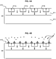
- FIGS. 4A to 4D illustrate steps of a method of manufacturing the support according to the invention.
- a master substrate M1 is used to order nano or microparticles before enclosing them in a non-magnetic matrix.
- Said master substrate M1 has a magnetically structured face, that is to say a face M10 consisting of a plurality of micro-sources M10a, M10b of magnetic field distributed in a given pattern.
- the magnetization of the different micro-sources is represented by an arrow.
- the magnetically structured face M10 of the master substrate is flat.
- a master substrate whose face is not flat but has cavities or studs, in order to reproduce in the film formed from the master substrate studs or complementary cavities.
- the master substrate can be manufactured by various techniques known to those skilled in the art.
- thermo-magnetic imprint structuring method or a method of structuring by topography as described above.
- the master substrate consists of a magnetically hard layer NdFeB M11 having a thickness of 5 microns on a support substrate M12 silicon and magnetically structured by thermo-magnetic imprint so as to form regions M10a of magnetization opposite to that of M10b regions.
- the intensity of the magnetic field and the magnetic field gradient is maximum at the interfaces between the regions M10a, M10b having opposite magnetizations.
- nanoparticles or microparticles having a positive magnetic susceptibility are attracted by the magnetophoretic force to these interfaces.
- the master substrate is however not limited to this particular form but may consist of hard or soft magnetic material structured by topography.
- the master substrate may optionally be an electrical conductor.
- this particular topography can be used to print a shape complementary to the final film.
- Nano or microparticles P of a hard magnetic material are sent to the magnetically structured face of the master substrate 1.
- the particles P agglomerate at the edges of each of the micro-sources.
- these agglomerates 21 generally have a triangular or trapezoidal section, with a wider base on the side of the master substrate M1 and decreasing with the distance.
- the master substrate is advantageously agitated in such a way as to optimize the trapping of the particles at the edges of the micro-sources of the magnetic field.
- a jet of dry gas can be sprayed to promote the trapping of particles at said edges and / or to remove non-trapped particles before deposition of the non-magnetic matrix.
- the particles are made of a hard magnetic material, which can be one of the materials of the list developed above.
- an external magnetic field will permanently magnetize and thus form a self-contained magnetically structured film.
- a matrix 22 of non-magnetic material in the form of a thin layer is then deposited on the agglomerated particles on the master substrate.
- the thickness of the matrix 22 is typically between 100 nm and 5 mm
- the matrix is made of an elastomeric material, which makes it possible to give the film a certain flexibility.
- the matrix is in one of the following materials: polydimethylsiloxane (PDMS), epoxy resin, rubber, bakelite, polymethyl methacrylate (PMMA), polystyrene ( PS), photosensitive resin, parylene, oxides such as SiO 2 , Al 2 O 3 , metals such as Cu, Ag, carbonaceous materials such as graphite, DLC, etc.
- PDMS polydimethylsiloxane
- PMMA polymethyl methacrylate
- PS polystyrene
- photosensitive resin parylene
- oxides such as SiO 2 , Al 2 O 3
- metals such as Cu
- Ag carbonaceous materials
- graphite graphite, DLC, etc.
- the matrix 22 is allowed to cure or crosslink for the appropriate duration.
- the matrix may advantageously be made of a transparent or translucent material.
- the skilled person is able to select an appropriate matrix among the products available on the market according to the desired properties.
- the film 2 consisting of the matrix 22 and agglomerates 21 of magnetic particles is delaminated with respect to the master substrate M1.
- the master substrate can be reused for the production of a new film.
- the master substrate requires the implementation of microfabrication techniques and therefore has a certain cost, it can be reused indefinitely and the manufacture of the magnetically structured film itself, which does not imply not such complex and expensive techniques, implements only inexpensive materials.
- This process is also easily industrializable and makes it possible to produce large-area films and in large quantities at low cost.
- a layer of a material that facilitates the delamination of the film and remains solid with the master substrate during delamination it is possible to deposit on the master substrate, before depositing the particles, a layer of a material that facilitates the delamination of the film and remains solid with the master substrate during delamination.
- the ordered micro-magnetic field sources are preferably arranged directly on the surface of the support - or in the immediate vicinity thereof - in contact with the sample to obtain maximum attraction forces.
- titration plates comprising a plurality of wells (e.g., 96 or 384 wells) are used in the immunodetection assays.
- This integration can be achieved by producing the plate itself in a suitable material to form ordered micro-field of magnetic field, according to one of the methods described above.
- the micro-sources of magnetic field are then preferably placed at the bottom of each of the wells.
- a titration plate in which the wells have no bottom, and to report under said plate a planar support containing ordered micro-magnetic field sources arranged at each level. well, so as to constitute the sealed bottom of said wells.
- the method is compatible with the supports usually used in immunoassay, which does not require modification of existing laboratory equipment.
- the support on which the complexes are immobilized is not a titration plate but a plane support on the surface of which are arranged a plurality of ordered micro-magnetic sources.
- Such a support can be achieved by the various methods of micro-structuring of magnetic layers described above.
- said support can be achieved by the method "Micro Magnetic Imprinting" described above.
- This manufacturing technique has the advantage of being able to manufacture a large quantity of supports at low cost, only the master substrate, which is reusable at will, being expensive.
- the support has the advantage of being able to be made of a transparent or translucent material.
- This property can in some cases facilitate detection and quantification by optical methods.
- the material of the support as a function of the detection method envisaged.
- the mixture of the molecule to be detected, the magnetic particles and the element able to bind selectively to said molecule is made in a container, then limited volumes of mixture are taken and deposited on said support. in the form of a drop, as illustrated on the figure 5 .
- the size of the drops depends on the deposited volume and the hydrophilicity of the support material. This size is therefore adjustable, typically between 1 microliter and 200 microliters.
- micro-sources of ordered magnetic field are advantageously distributed over the surface of the support in a regular pattern, so as to allow the capture of the complexes regardless of the region of the medium on which the drop has been deposited.
- the location intended for each drop is preferably materialized on the plane support, for example by a local magnetic marking, or chemically (by making the surface of the support locally hydrophilic or hydrophobic), or even topographically, by a shallow recess achieved. in the surface of the support. It is also possible to visually mark the location to help the experimenter locate it.
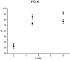
- the magnetic beads capture rate was substantially higher in drops deposited on such a plane support than in a solution deposited in a well of a titration plate.
- the figure 6 shows the percentage of beads of 100 nm in diameter captured in a drop respectively (data represented by a disc) and the quantity of balls of the same type captured in a well (data represented by a square).
- plane support with respect to a conventional titration plate is that it allows, for the same size of the support, to provide more sites for capturing molecules.
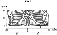
- the magnetic particles closest to the surface of the support are quickly attracted by the ordered micro-magnetic field sources, and their drag hydrodynamically drives the movement of more distant particles towards the micro-sources of magnetic field, which, a once brought closer to the surface of the support, are in turn attracted magnetically.
- This junction simulates an element of a matrix of ordered micro-sources of magnetic field produced by the Thermo Magnetic Patterning technique described above.
- the field of velocities of the fluid measured corresponds, to within 10%, to what is calculated by the hydrodynamic-magnetic coupling model described above.
- the support may be a microfluidic system of "lab-on-chip” type.
- the support then comprises a microchannel and an array of magnetic micro-sources arranged in an ordered manner in at least one wall of said channel.
- Said microchannel can be produced according to the "Micro Magnetic Imprinting" method described above.
- the magnetically structured face of the master substrate 1 is not flat but has at least one stud or a cavity whose negative will be present on the film.
- the magnetically structured face 10 of the master substrate 1 has a raised stud 10 ', the surface of the stud consisting of a plurality of magnetic field micro-sources 10a, 10b.
- said pad may have a parallelepipedal shape.
- the rest of the surface of the master substrate may also be magnetically structured, but it is also conceivable that only the surface of the pad 10 'is magnetically structured; in the latter case, the nanoparticles or microparticles made will agglomerate only at the edges of the magnetic micro-sources constituting the surface of the pad 10 ', the rest of the surface of the master substrate not holding particles.
- nano or magnetic microparticles are provided on the master substrate, which are ordered and agglomerate into three-dimensional structures 20 at the edges of the magnetic field micro-sources 10a, 10b ( Figure 7B ).
- the non-magnetic matrix 3 is deposited on the master substrate.
- the film 4 thus obtained illustrated in FIG. Figure 7D thus has a cavity 40 complementary to the pad 10 'of the master substrate.
- the film thus comprises one or more wells, or one or more channels.
- microfluidic channel From such a film, one can thus form a microfluidic channel.
- said flat film 4 ' can also be manufactured according to the invention and comprise on its surface three-dimensional magnetic structures 20'.
- a device 6 comprising a micro-channel 60 which has, on two opposite walls 61a and 61b, a magnetically structured surface.
- a surface treatment can make it possible to seal the two films.
- both films have a PDMS matrix
- an activation of the surfaces by an oxygen plasma can be performed.
- the nature of the magnetic particles, as well as their distribution with respect to the surface of each wall, may be identical for each of the two walls or be different.
- the mixture is injected at the inlet of the microchannel: the solution circulates in the microchannel, the complexes being progressively immobilized on the bottom of the microchannel by the micro-sources of magnetic field.
- a washing step can then optionally be carried out to remove the residues from the solution, the complexes remaining magnetically trapped by the micro-sources located on the walls of the channel.
- One embodiment of the invention has been validated in a test assay of a "sandwich" type antigen performed under the following conditions.
- the concentrations used were 1.3 nM for the capture antibody, 10 9 / ml for the superparamagnetic beads and 10 10 / ml for the quantum dots.
- the quantum dots, the beads functionalized with the antibody and the biotinylated antigen were placed, during the same step, on a flexible substrate comprising micro-sources of magnetic field.
- the mixing / capture time was set at 7 minutes.
- the figure 8 illustrates fluorescence (in arbitrary units) as a function of antigen concentration.
- the whole test was done in about ten minutes.
- the detection limit is 10 ⁇ M, which is comparable to the limit of commercially available ELISA tests conducted on this protein.
- the spatial organization of the ordered micro-magnetic field sources makes it possible to detect without washing the support or labeling the immuno-complexes.
- This detection can be done by fluorescence, by focussing the image on the surface of the medium containing the magnetic field micro-sources, or by having surface detectors of the support itself.
- Magnetic nanoparticles (50 nm, 10 9 ml -1 ) and non-magnetic fluorescent nanoparticles (quantum dots, 30 nm, 10 9 ml -1 ) functionalized with biotin were mixed at low concentrations of avidin, which is a protein that binds almost irreversibly to four molecules of biotin.
- a drop is deposited on the surface of a support comprising ordered micro-sources of magnetic field produced by the Micro-Magnetic Imprinting technique and observed under a fluorescence optical microscope 10 minutes later.
- the microscope is focused at the level of the support.
- the image at the top left shows the structure of the support comprising the ordered magnetic field micropores observed in phase contrast (the magnetic field micro-sources being arranged in a grid that has a darker color than the rest of the the matrix) while the image at the bottom left shows the distribution of biotinylated quantum dots on the surface of the support in the presence of biotinylated magnetic nanoparticles and avidin, observed in fluorescence (the quantum dots present a light color in this image) .
- the superposition of the two images to the right of the figure 10A allows to see the quantum dots resulting from a specific interaction with the magnetic nanoparticles: it is clear that the quantum dots (of light color) are mainly aligned along the grid (of dark color) defined by the micro-sources of magnetic field (specific signal) and thus reproduce the pattern defined by the micro-sources of magnetic field, only few quantum dots being on areas within this grid (non-specific signal).
- the fluorescence density on the high and low magnetic field gradient regions was measured on the microscopy images shown in A.
- the figure 10B shows the evolution of the ratio (specific signal) / (non-specific signal), which is equal to the ratio (specific fluorescence x area of regions with low magnetic field gradient) / (non-specific fluorescence x area of high gradient field regions magnetic) as a function of avidin concentration.
- this ratio is 1.
- the shaded area corresponds to the 6-sigma confidence interval. All points outside this area are significant with a probability of error less than 10 -6 .
- a concentration of 50 nM is therefore detectable at the 99.9997% significance level (six sigmas).
- microstructuring of ordered micro-sources of magnetic field makes it possible to define the "specific” and “non-specific” regions of interest. It can therefore be used to simplify detection.
- micro-sources of magnetic field that would be arranged randomly would not allow this detection without washing.
Landscapes
- Health & Medical Sciences (AREA)
- Immunology (AREA)
- Life Sciences & Earth Sciences (AREA)
- Chemical & Material Sciences (AREA)
- Engineering & Computer Science (AREA)
- Molecular Biology (AREA)
- Biomedical Technology (AREA)
- Urology & Nephrology (AREA)
- Hematology (AREA)
- Pathology (AREA)
- General Health & Medical Sciences (AREA)
- Analytical Chemistry (AREA)
- Biochemistry (AREA)
- General Physics & Mathematics (AREA)
- Physics & Mathematics (AREA)
- Chemical Kinetics & Catalysis (AREA)
- Biotechnology (AREA)
- Microbiology (AREA)
- Cell Biology (AREA)
- Food Science & Technology (AREA)
- Medicinal Chemistry (AREA)
- Electrochemistry (AREA)
- Apparatus Associated With Microorganisms And Enzymes (AREA)
- Investigating, Analyzing Materials By Fluorescence Or Luminescence (AREA)
- Investigating Or Analyzing Materials By The Use Of Magnetic Means (AREA)
- Peptides Or Proteins (AREA)
Claims (9)
- Verfahren zum Einfangen eines Moleküls in einer Probe, umfassend die folgenden Schritte:a) Mischen der Probe mit magnetischen Teilchen, wobei jedes der Teilchen mit einem Element gekoppelt ist, das fähig ist, selektiv an das einzufangende Molekül zu binden, um mindestens einen Komplex zu bilden, der ein magnetisches Teilchen, das Element und das an das Element gebundene Molekül umfasst, wobei diese magnetischen Teilchen einen Durchmesser im Bereich zwischen 5 nm und 500 nm aufweisen, dannb) Aufbringen eines Tropfens des nach Abschluss des Schritts a) erhaltenen Gemisches auf einen Träger, wobei dieser Träger eine ebene Platte ist, auf deren Oberfläche sich auf eine bestimmte Weise angeordnete Mikro-Magnetfeldquellen befinden,c) Immobilisieren des mindestens einen Komplexes auf dem Träger, der auf eine bestimmte Weise angeordnete Mikro-Magnetfeldquellen umfasst,dadurch gekennzeichnet, dass die Konzentration der magnetischen Teilchen in dem nach Abschluss des Schritts a) erhaltenen Gemisches größer als 106 Teilchen/ml ist.
- Verfahren nach Anspruch 1, dadurch gekennzeichnet, dass der Träger eine nichtmagnetische Matrix umfasst, die eine Vielzahl von in einer bestimmten Weise angeordneten dreidimensionalen Agglomeraten von magnetisierten Mikro- oder Nanopartikeln aus hart- oder weichmagnetischem Material enthält, wobei die Agglomerate die Mikro-Magnetfeldquellen bilden.
- Verfahren nach einem der Ansprüche 1 bis 2, dadurch gekennzeichnet, dass das einzufangende Molekül ein Antigen ist, und dadurch, dass das Element, das fähig ist, an das Molekül zu binden, ein Rezeptor-Antikörper des Antigens ist.
- Verfahren nach Anspruch 3, dadurch gekennzeichnet, dass dem Gemisch ein sogenannter Nachweisantikörper zugesetzt wird, der einen fluoreszierenden, lumineszierenden oder kolorimetrischen Marker trägt, wobei der Antikörper fähig ist, an das Antigen zu binden, das an den mit dem Magnetteilchen gekoppelten Antikörper gebunden ist.
- Verfahren nach einem der Ansprüche 1 bis 2, dadurch gekennzeichnet, dass das einzufangende Molekül ein Antikörper ist, und dadurch, dass das Element, das fähig ist, an das Molekül zu binden, ein Antigen ist, das von dem Antikörper erkannt wird.
- Verfahren nach einem der Ansprüche 1 bis 5, dadurch gekennzeichnet, dass es nach der Immobilisierung des mindestens einen Komplexes auf dem Träger einen Schritt des Waschens des Trägers umfasst, um die Probe herauszuwaschen, während der mindestens eine Komplex durch die auf eine bestimmte Weise angeordneten Mikro-Magnetfeldquellen auf dem Träger zurückgehalten wird.
- Verfahren zum Erfassen eines Moleküls in einer Probe, umfassend die folgenden Schritte:- Einfangen des Moleküls auf einem Träger mittels des Verfahrens zum Einfangen nach einem der Ansprüche 1 bis 5,- Erfassen des auf dem Träger festgehaltenen Moleküls durch Fluoreszenz, Lumineszenz, Kolorimetrie, Elektrochemie und/oder Radiometrie.
- Verfahren nach Anspruch 7, dadurch gekennzeichnet, dass der Erfassungsschritt direkt nach dem Einfangschritt ohne Zwischenschritt des Waschens des Trägers ausgeführt wird.
- Verfahren nach Anspruch 7, dadurch gekennzeichnet, dass es zwischen dem Einfangschritt und dem Erfassungsschritt einen Schritt des Waschens des Trägers umfasst, um die Probe herauszuwaschen, während der mindestens eine Komplex durch die auf eine bestimmte Weise angeordneten Mikro-Magnetfeldquellen auf dem Träger zurückgehalten wird.
Priority Applications (1)
| Application Number | Priority Date | Filing Date | Title |
|---|---|---|---|
| EP18191274.2A EP3447492B1 (de) | 2013-01-17 | 2013-11-26 | Verfahren zum einfangen und entdecken ohne waschen eines moleküls in einer probe |
Applications Claiming Priority (2)
| Application Number | Priority Date | Filing Date | Title |
|---|---|---|---|
| FR1350421A FR3001038B1 (fr) | 2013-01-17 | 2013-01-17 | Procede de capture, procede de detection et kit de capture d'une molecule dans un echantillon |
| PCT/EP2013/074736 WO2014111187A1 (fr) | 2013-01-17 | 2013-11-26 | Procede de capture, procede de detection et kit de capture d'une molecule dans un echantillon |
Related Child Applications (2)
| Application Number | Title | Priority Date | Filing Date |
|---|---|---|---|
| EP18191274.2A Division EP3447492B1 (de) | 2013-01-17 | 2013-11-26 | Verfahren zum einfangen und entdecken ohne waschen eines moleküls in einer probe |
| EP18191274.2A Division-Into EP3447492B1 (de) | 2013-01-17 | 2013-11-26 | Verfahren zum einfangen und entdecken ohne waschen eines moleküls in einer probe |
Publications (2)
| Publication Number | Publication Date |
|---|---|
| EP2946209A1 EP2946209A1 (de) | 2015-11-25 |
| EP2946209B1 true EP2946209B1 (de) | 2018-11-14 |
Family
ID=47989254
Family Applications (2)
| Application Number | Title | Priority Date | Filing Date |
|---|---|---|---|
| EP13795765.0A Active EP2946209B1 (de) | 2013-01-17 | 2013-11-26 | Verfahren zur erfassung eines moleküls in einer probe |
| EP18191274.2A Active EP3447492B1 (de) | 2013-01-17 | 2013-11-26 | Verfahren zum einfangen und entdecken ohne waschen eines moleküls in einer probe |
Family Applications After (1)
| Application Number | Title | Priority Date | Filing Date |
|---|---|---|---|
| EP18191274.2A Active EP3447492B1 (de) | 2013-01-17 | 2013-11-26 | Verfahren zum einfangen und entdecken ohne waschen eines moleküls in einer probe |
Country Status (6)
| Country | Link |
|---|---|
| US (1) | US10451617B2 (de) |
| EP (2) | EP2946209B1 (de) |
| ES (1) | ES2711422T3 (de) |
| FR (1) | FR3001038B1 (de) |
| TR (1) | TR201902171T4 (de) |
| WO (1) | WO2014111187A1 (de) |
Families Citing this family (12)
| Publication number | Priority date | Publication date | Assignee | Title |
|---|---|---|---|---|
| DK2800970T3 (en) | 2012-01-04 | 2017-01-16 | Magnomics S A | Monolithic device for combining CMOS with magnetoresistive sensors |
| US10732178B2 (en) * | 2013-01-29 | 2020-08-04 | Bio-Rad Haifa Ltd. | Detection assays employing magnetic nanoparticles |
| US20150024376A1 (en) * | 2013-07-19 | 2015-01-22 | Battelle Memorial Institute | Trap and flow system and process for capture of target analytes |
| FR3046797A1 (fr) * | 2016-01-15 | 2017-07-21 | Biofilm Control | Procede de detection rapide de sensibilite de microorganismes aux drogues |
| CN107462726B (zh) * | 2017-07-28 | 2019-06-21 | 佛山市烨泰科技有限公司 | 一种基于双单抗夹心的磁酶免疫双重定量elisa检测方法 |
| CN107478837B (zh) * | 2017-09-01 | 2018-12-14 | 北京华科泰生物技术有限公司 | 基于磁微粒的微流控化学发光检测系统及其应用 |
| FR3100338B1 (fr) * | 2019-08-30 | 2022-09-02 | Centre Nat Rech Scient | Kit et méthode de capture d’une molécule |
| FR3116215B1 (fr) | 2020-11-17 | 2024-03-29 | Magia Diagnostics | Cartouche comportant une pluralite de chambres d’analyse pour recevoir un liquide biologique |
| FR3120126B1 (fr) | 2021-02-23 | 2025-12-19 | Magia Diagnostics | Cartouche d’analyse et dispositif d’analyse d’un liquide |
| FR3120127B1 (fr) * | 2021-02-24 | 2023-09-15 | Magia Diagnostics | Procede et dispositif d’analyse d’un liquide susceptible de contenir un analyte |
| FR3138527B1 (fr) | 2022-07-28 | 2025-06-27 | Magia Diagnostics | dispositif d’analyse d’un liquide |
| CN115646562B (zh) * | 2022-09-27 | 2023-08-11 | 郑州大学 | 基于微磁作用的操控芯片、检测组件和检测系统、方法 |
Family Cites Families (5)
| Publication number | Priority date | Publication date | Assignee | Title |
|---|---|---|---|---|
| JP2002503334A (ja) * | 1996-09-04 | 2002-01-29 | テクニカル ユニバーシティ オブ デンマーク | 粒子の分離と分析用のマイクロフローシステム |
| EP1409134A2 (de) * | 2000-11-16 | 2004-04-21 | Prolinx, Inc. | Magnetplatte für biologische trennungen |
| US20040018611A1 (en) * | 2002-07-23 | 2004-01-29 | Ward Michael Dennis | Microfluidic devices for high gradient magnetic separation |
| FR2900763A1 (fr) * | 2006-05-02 | 2007-11-09 | Commissariat Energie Atomique | Structure a aimants permanents pour le piegeage et/ou le guidage de particules diamagnetiques |
| FR2991096B1 (fr) * | 2012-05-22 | 2014-06-20 | Centre Nat Rech Scient | Procede de fabrication d'un film comprenant des microstructures magnetiques tridimensionnelles |
-
2013
- 2013-01-17 FR FR1350421A patent/FR3001038B1/fr active Active
- 2013-11-26 TR TR2019/02171T patent/TR201902171T4/tr unknown
- 2013-11-26 ES ES13795765T patent/ES2711422T3/es active Active
- 2013-11-26 EP EP13795765.0A patent/EP2946209B1/de active Active
- 2013-11-26 WO PCT/EP2013/074736 patent/WO2014111187A1/fr not_active Ceased
- 2013-11-26 US US14/761,087 patent/US10451617B2/en active Active
- 2013-11-26 EP EP18191274.2A patent/EP3447492B1/de active Active
Non-Patent Citations (1)
| Title |
|---|
| None * |
Also Published As
| Publication number | Publication date |
|---|---|
| EP2946209A1 (de) | 2015-11-25 |
| EP3447492C0 (de) | 2025-01-29 |
| US20150355174A1 (en) | 2015-12-10 |
| EP3447492B1 (de) | 2025-01-29 |
| FR3001038A1 (fr) | 2014-07-18 |
| FR3001038B1 (fr) | 2018-02-09 |
| TR201902171T4 (tr) | 2019-03-21 |
| ES2711422T3 (es) | 2019-05-03 |
| WO2014111187A1 (fr) | 2014-07-24 |
| EP3447492A1 (de) | 2019-02-27 |
| US10451617B2 (en) | 2019-10-22 |
Similar Documents
| Publication | Publication Date | Title |
|---|---|---|
| EP3447492B1 (de) | Verfahren zum einfangen und entdecken ohne waschen eines moleküls in einer probe | |
| EP2852959B1 (de) | Herstellungsverfahren einer dünnen schicht enthaltend magnetische dreidimensionale mikrostrukturen | |
| CN101523212B (zh) | 具有试剂层的快速生物传感器 | |
| EP1446666B1 (de) | Verfahren zum nachweis von analyten durch magnetischen teilchen | |
| Dempsey et al. | Micro-magnetic imprinting of high field gradient magnetic flux sources | |
| JP2010540888A (ja) | センサカートリッジ | |
| CN104395751B (zh) | 含有干扰颗粒的流体的处理 | |
| Yassine et al. | Isolation of cells for selective treatment and analysis using a magnetic microfluidic chip | |
| Li et al. | A magnetic method to concentrate and trap biological targets | |
| Dey et al. | Recent advances in magnetoresistance biosensors: A short review | |
| EP4022308B1 (de) | Kit und molekül zur erfassung eines moleküls mit magnetischen mitteln | |
| Class et al. | Patent application title: METHOD FOR CAPTURING, METHOD FOR DETECTING AND KIT FOR CAPTURING A MOLECULE IN A SAMPLE Inventors: Guillaume Blair (Magland, FR) Luiz Fernando Zanini (Grenoble, FR) Gilbert Reyne (Marseille, FR) Nora Dempsey (Grenoble, FR) Marianne Weidenhaupt (St Joseph De Rivière, FR) Franz Bruckert (Grenoble, FR) Orphee Cugat (Poisat, FR) Assignees: Centre National De La Recherche Scientifique (CNRS) | |
| RU2821351C1 (ru) | Набор и способ захвата молекулы магнитными средствами | |
| FR2900763A1 (fr) | Structure a aimants permanents pour le piegeage et/ou le guidage de particules diamagnetiques | |
| Doan | Optical Nanopore Sensors for Quantitative Analysis of Dilute Analytes | |
| Bou et al. | Fast and precise magnetophoresis of superparamagnetic nanoparticles on a micro-magnetic substrate in a static liquid environment | |
| TWI665441B (zh) | 雙邊不對稱顆粒、具有雙邊不對稱顆粒的四面體聚合結構、雙邊不對稱顆粒的製作方法及檢測生物分子之方法 | |
| Earhart | A microfabricated magnetic sifter and high throughput physical fabrication of magnetic nanoparticles for applications in protein and cell separation | |
| Van Ommering | Dynamics of individual magnetic particles near a biosensor surface | |
| Brzeska | Development of magnetic tunnel junction (MTJ) sensors for the detection of single magnetic particles | |
| Altman | Manipulation and detection of superparamagnetic beads with spin-valves |
Legal Events
| Date | Code | Title | Description |
|---|---|---|---|
| PUAI | Public reference made under article 153(3) epc to a published international application that has entered the european phase |
Free format text: ORIGINAL CODE: 0009012 |
|
| 17P | Request for examination filed |
Effective date: 20150710 |
|
| AK | Designated contracting states |
Kind code of ref document: A1 Designated state(s): AL AT BE BG CH CY CZ DE DK EE ES FI FR GB GR HR HU IE IS IT LI LT LU LV MC MK MT NL NO PL PT RO RS SE SI SK SM TR |
|
| AX | Request for extension of the european patent |
Extension state: BA ME |
|
| DAX | Request for extension of the european patent (deleted) | ||
| STAA | Information on the status of an ep patent application or granted ep patent |
Free format text: STATUS: EXAMINATION IS IN PROGRESS |
|
| 17Q | First examination report despatched |
Effective date: 20180115 |
|
| GRAP | Despatch of communication of intention to grant a patent |
Free format text: ORIGINAL CODE: EPIDOSNIGR1 |
|
| STAA | Information on the status of an ep patent application or granted ep patent |
Free format text: STATUS: GRANT OF PATENT IS INTENDED |
|
| RIC1 | Information provided on ipc code assigned before grant |
Ipc: G01N 27/74 20060101ALI20180514BHEP Ipc: H01F 1/00 20060101ALI20180514BHEP Ipc: G01N 33/543 20060101AFI20180514BHEP |
|
| INTG | Intention to grant announced |
Effective date: 20180613 |
|
| RAP1 | Party data changed (applicant data changed or rights of an application transferred) |
Owner name: INSTITUT POLYTECHNIQUE DE GRENOBLE Owner name: CENTRE NATIONAL DE LA RECHERCHE SCIENTIFIQUE (CNRS |
|
| RIN1 | Information on inventor provided before grant (corrected) |
Inventor name: BRUCKERT, FRANZ Inventor name: WEIDENHAUPT, MARIANNE Inventor name: ZANINI, LUIZ FERNANDO Inventor name: REYNE, GILBERT Inventor name: CUGAT, ORPHEE Inventor name: DEMPSEY, NORA Inventor name: BLAIRE, GUILLAUME |
|
| GRAS | Grant fee paid |
Free format text: ORIGINAL CODE: EPIDOSNIGR3 |
|
| GRAA | (expected) grant |
Free format text: ORIGINAL CODE: 0009210 |
|
| STAA | Information on the status of an ep patent application or granted ep patent |
Free format text: STATUS: THE PATENT HAS BEEN GRANTED |
|
| AK | Designated contracting states |
Kind code of ref document: B1 Designated state(s): AL AT BE BG CH CY CZ DE DK EE ES FI FR GB GR HR HU IE IS IT LI LT LU LV MC MK MT NL NO PL PT RO RS SE SI SK SM TR |
|
| REG | Reference to a national code |
Ref country code: CH Ref legal event code: EP Ref country code: AT Ref legal event code: REF Ref document number: 1065436 Country of ref document: AT Kind code of ref document: T Effective date: 20181115 |
|
| REG | Reference to a national code |
Ref country code: DE Ref legal event code: R096 Ref document number: 602013046788 Country of ref document: DE |
|
| REG | Reference to a national code |
Ref country code: IE Ref legal event code: FG4D Free format text: LANGUAGE OF EP DOCUMENT: FRENCH |
|
| REG | Reference to a national code |
Ref country code: CH Ref legal event code: NV Representative=s name: LLR, CH |
|
| REG | Reference to a national code |
Ref country code: NL Ref legal event code: MP Effective date: 20181114 |
|
| REG | Reference to a national code |
Ref country code: LT Ref legal event code: MG4D |
|
| REG | Reference to a national code |
Ref country code: SE Ref legal event code: TRGR |
|
| REG | Reference to a national code |
Ref country code: AT Ref legal event code: MK05 Ref document number: 1065436 Country of ref document: AT Kind code of ref document: T Effective date: 20181114 |
|
| PG25 | Lapsed in a contracting state [announced via postgrant information from national office to epo] |
Ref country code: LV Free format text: LAPSE BECAUSE OF FAILURE TO SUBMIT A TRANSLATION OF THE DESCRIPTION OR TO PAY THE FEE WITHIN THE PRESCRIBED TIME-LIMIT Effective date: 20181114 Ref country code: AT Free format text: LAPSE BECAUSE OF FAILURE TO SUBMIT A TRANSLATION OF THE DESCRIPTION OR TO PAY THE FEE WITHIN THE PRESCRIBED TIME-LIMIT Effective date: 20181114 Ref country code: IS Free format text: LAPSE BECAUSE OF FAILURE TO SUBMIT A TRANSLATION OF THE DESCRIPTION OR TO PAY THE FEE WITHIN THE PRESCRIBED TIME-LIMIT Effective date: 20190314 Ref country code: FI Free format text: LAPSE BECAUSE OF FAILURE TO SUBMIT A TRANSLATION OF THE DESCRIPTION OR TO PAY THE FEE WITHIN THE PRESCRIBED TIME-LIMIT Effective date: 20181114 Ref country code: HR Free format text: LAPSE BECAUSE OF FAILURE TO SUBMIT A TRANSLATION OF THE DESCRIPTION OR TO PAY THE FEE WITHIN THE PRESCRIBED TIME-LIMIT Effective date: 20181114 Ref country code: BG Free format text: LAPSE BECAUSE OF FAILURE TO SUBMIT A TRANSLATION OF THE DESCRIPTION OR TO PAY THE FEE WITHIN THE PRESCRIBED TIME-LIMIT Effective date: 20190214 Ref country code: LT Free format text: LAPSE BECAUSE OF FAILURE TO SUBMIT A TRANSLATION OF THE DESCRIPTION OR TO PAY THE FEE WITHIN THE PRESCRIBED TIME-LIMIT Effective date: 20181114 |
|
| REG | Reference to a national code |
Ref country code: ES Ref legal event code: FG2A Ref document number: 2711422 Country of ref document: ES Kind code of ref document: T3 Effective date: 20190503 |
|
| REG | Reference to a national code |
Ref country code: NO Ref legal event code: T2 Effective date: 20181114 |
|
| PG25 | Lapsed in a contracting state [announced via postgrant information from national office to epo] |
Ref country code: RS Free format text: LAPSE BECAUSE OF FAILURE TO SUBMIT A TRANSLATION OF THE DESCRIPTION OR TO PAY THE FEE WITHIN THE PRESCRIBED TIME-LIMIT Effective date: 20181114 Ref country code: GR Free format text: LAPSE BECAUSE OF FAILURE TO SUBMIT A TRANSLATION OF THE DESCRIPTION OR TO PAY THE FEE WITHIN THE PRESCRIBED TIME-LIMIT Effective date: 20190215 Ref country code: NL Free format text: LAPSE BECAUSE OF FAILURE TO SUBMIT A TRANSLATION OF THE DESCRIPTION OR TO PAY THE FEE WITHIN THE PRESCRIBED TIME-LIMIT Effective date: 20181114 Ref country code: PT Free format text: LAPSE BECAUSE OF FAILURE TO SUBMIT A TRANSLATION OF THE DESCRIPTION OR TO PAY THE FEE WITHIN THE PRESCRIBED TIME-LIMIT Effective date: 20190314 Ref country code: AL Free format text: LAPSE BECAUSE OF FAILURE TO SUBMIT A TRANSLATION OF THE DESCRIPTION OR TO PAY THE FEE WITHIN THE PRESCRIBED TIME-LIMIT Effective date: 20181114 |
|
| PG25 | Lapsed in a contracting state [announced via postgrant information from national office to epo] |
Ref country code: LU Free format text: LAPSE BECAUSE OF NON-PAYMENT OF DUE FEES Effective date: 20181126 Ref country code: PL Free format text: LAPSE BECAUSE OF FAILURE TO SUBMIT A TRANSLATION OF THE DESCRIPTION OR TO PAY THE FEE WITHIN THE PRESCRIBED TIME-LIMIT Effective date: 20181114 Ref country code: CZ Free format text: LAPSE BECAUSE OF FAILURE TO SUBMIT A TRANSLATION OF THE DESCRIPTION OR TO PAY THE FEE WITHIN THE PRESCRIBED TIME-LIMIT Effective date: 20181114 Ref country code: DK Free format text: LAPSE BECAUSE OF FAILURE TO SUBMIT A TRANSLATION OF THE DESCRIPTION OR TO PAY THE FEE WITHIN THE PRESCRIBED TIME-LIMIT Effective date: 20181114 |
|
| REG | Reference to a national code |
Ref country code: DE Ref legal event code: R097 Ref document number: 602013046788 Country of ref document: DE |
|
| PG25 | Lapsed in a contracting state [announced via postgrant information from national office to epo] |
Ref country code: RO Free format text: LAPSE BECAUSE OF FAILURE TO SUBMIT A TRANSLATION OF THE DESCRIPTION OR TO PAY THE FEE WITHIN THE PRESCRIBED TIME-LIMIT Effective date: 20181114 Ref country code: SK Free format text: LAPSE BECAUSE OF FAILURE TO SUBMIT A TRANSLATION OF THE DESCRIPTION OR TO PAY THE FEE WITHIN THE PRESCRIBED TIME-LIMIT Effective date: 20181114 Ref country code: EE Free format text: LAPSE BECAUSE OF FAILURE TO SUBMIT A TRANSLATION OF THE DESCRIPTION OR TO PAY THE FEE WITHIN THE PRESCRIBED TIME-LIMIT Effective date: 20181114 Ref country code: SM Free format text: LAPSE BECAUSE OF FAILURE TO SUBMIT A TRANSLATION OF THE DESCRIPTION OR TO PAY THE FEE WITHIN THE PRESCRIBED TIME-LIMIT Effective date: 20181114 Ref country code: MC Free format text: LAPSE BECAUSE OF FAILURE TO SUBMIT A TRANSLATION OF THE DESCRIPTION OR TO PAY THE FEE WITHIN THE PRESCRIBED TIME-LIMIT Effective date: 20181114 |
|
| PLBE | No opposition filed within time limit |
Free format text: ORIGINAL CODE: 0009261 |
|
| STAA | Information on the status of an ep patent application or granted ep patent |
Free format text: STATUS: NO OPPOSITION FILED WITHIN TIME LIMIT |
|
| 26N | No opposition filed |
Effective date: 20190815 |
|
| PG25 | Lapsed in a contracting state [announced via postgrant information from national office to epo] |
Ref country code: SI Free format text: LAPSE BECAUSE OF FAILURE TO SUBMIT A TRANSLATION OF THE DESCRIPTION OR TO PAY THE FEE WITHIN THE PRESCRIBED TIME-LIMIT Effective date: 20181114 |
|
| PG25 | Lapsed in a contracting state [announced via postgrant information from national office to epo] |
Ref country code: MT Free format text: LAPSE BECAUSE OF FAILURE TO SUBMIT A TRANSLATION OF THE DESCRIPTION OR TO PAY THE FEE WITHIN THE PRESCRIBED TIME-LIMIT Effective date: 20181114 |
|
| PG25 | Lapsed in a contracting state [announced via postgrant information from national office to epo] |
Ref country code: HU Free format text: LAPSE BECAUSE OF FAILURE TO SUBMIT A TRANSLATION OF THE DESCRIPTION OR TO PAY THE FEE WITHIN THE PRESCRIBED TIME-LIMIT; INVALID AB INITIO Effective date: 20131126 Ref country code: MK Free format text: LAPSE BECAUSE OF NON-PAYMENT OF DUE FEES Effective date: 20181114 Ref country code: CY Free format text: LAPSE BECAUSE OF FAILURE TO SUBMIT A TRANSLATION OF THE DESCRIPTION OR TO PAY THE FEE WITHIN THE PRESCRIBED TIME-LIMIT Effective date: 20181114 |
|
| P01 | Opt-out of the competence of the unified patent court (upc) registered |
Effective date: 20230515 |
|
| REG | Reference to a national code |
Ref country code: CH Ref legal event code: U11 Free format text: ST27 STATUS EVENT CODE: U-0-0-U10-U11 (AS PROVIDED BY THE NATIONAL OFFICE) Effective date: 20260108 |
|
| PGFP | Annual fee paid to national office [announced via postgrant information from national office to epo] |
Ref country code: GB Payment date: 20251126 Year of fee payment: 13 |
|
| PGFP | Annual fee paid to national office [announced via postgrant information from national office to epo] |
Ref country code: NO Payment date: 20251126 Year of fee payment: 13 |
|
| PGFP | Annual fee paid to national office [announced via postgrant information from national office to epo] |
Ref country code: IT Payment date: 20251126 Year of fee payment: 13 |
|
| PGFP | Annual fee paid to national office [announced via postgrant information from national office to epo] |
Ref country code: FR Payment date: 20251127 Year of fee payment: 13 |
|
| PGFP | Annual fee paid to national office [announced via postgrant information from national office to epo] |
Ref country code: TR Payment date: 20251124 Year of fee payment: 13 Ref country code: BE Payment date: 20251127 Year of fee payment: 13 |
|
| PGFP | Annual fee paid to national office [announced via postgrant information from national office to epo] |
Ref country code: SE Payment date: 20251126 Year of fee payment: 13 |
|
| PGFP | Annual fee paid to national office [announced via postgrant information from national office to epo] |
Ref country code: IE Payment date: 20251126 Year of fee payment: 13 |
|
| PGFP | Annual fee paid to national office [announced via postgrant information from national office to epo] |
Ref country code: ES Payment date: 20260203 Year of fee payment: 13 |
|
| PGFP | Annual fee paid to national office [announced via postgrant information from national office to epo] |
Ref country code: DE Payment date: 20251224 Year of fee payment: 13 |
|
| PGFP | Annual fee paid to national office [announced via postgrant information from national office to epo] |
Ref country code: CH Payment date: 20260108 Year of fee payment: 13 |