EP2946168B1 - Method and apparatus for creating map data - Google Patents
Method and apparatus for creating map data Download PDFInfo
- Publication number
- EP2946168B1 EP2946168B1 EP14700747.0A EP14700747A EP2946168B1 EP 2946168 B1 EP2946168 B1 EP 2946168B1 EP 14700747 A EP14700747 A EP 14700747A EP 2946168 B1 EP2946168 B1 EP 2946168B1
- Authority
- EP
- European Patent Office
- Prior art keywords
- map
- zones
- data
- accident
- events
- Prior art date
- Legal status (The legal status is an assumption and is not a legal conclusion. Google has not performed a legal analysis and makes no representation as to the accuracy of the status listed.)
- Active
Links
- 238000000034 method Methods 0.000 title claims description 27
- 238000004891 communication Methods 0.000 claims description 43
- 206010039203 Road traffic accident Diseases 0.000 claims description 15
- 238000005315 distribution function Methods 0.000 claims description 11
- 238000012545 processing Methods 0.000 claims description 8
- 238000004364 calculation method Methods 0.000 claims description 7
- 238000004590 computer program Methods 0.000 claims description 5
- 230000002708 enhancing effect Effects 0.000 claims description 3
- 230000005540 biological transmission Effects 0.000 claims 2
- 238000012423 maintenance Methods 0.000 claims 1
- 238000005516 engineering process Methods 0.000 description 17
- 206010027146 Melanoderma Diseases 0.000 description 6
- 238000003745 diagnosis Methods 0.000 description 5
- 238000009826 distribution Methods 0.000 description 5
- 238000003032 molecular docking Methods 0.000 description 4
- 238000001228 spectrum Methods 0.000 description 4
- 239000013598 vector Substances 0.000 description 4
- 238000004422 calculation algorithm Methods 0.000 description 3
- 230000008878 coupling Effects 0.000 description 3
- 238000010168 coupling process Methods 0.000 description 3
- 238000005859 coupling reaction Methods 0.000 description 3
- 238000013500 data storage Methods 0.000 description 3
- 230000006870 function Effects 0.000 description 3
- 230000004927 fusion Effects 0.000 description 3
- 230000001133 acceleration Effects 0.000 description 2
- 238000004458 analytical method Methods 0.000 description 2
- 238000013461 design Methods 0.000 description 2
- 238000001514 detection method Methods 0.000 description 2
- 238000012805 post-processing Methods 0.000 description 2
- 238000013459 approach Methods 0.000 description 1
- 239000000872 buffer Substances 0.000 description 1
- 230000010267 cellular communication Effects 0.000 description 1
- 239000004020 conductor Substances 0.000 description 1
- 238000007796 conventional method Methods 0.000 description 1
- 230000001186 cumulative effect Effects 0.000 description 1
- 230000001419 dependent effect Effects 0.000 description 1
- 238000010586 diagram Methods 0.000 description 1
- 238000006073 displacement reaction Methods 0.000 description 1
- 239000000835 fiber Substances 0.000 description 1
- 238000007429 general method Methods 0.000 description 1
- 230000010354 integration Effects 0.000 description 1
- 238000010295 mobile communication Methods 0.000 description 1
- 230000003287 optical effect Effects 0.000 description 1
- 230000002265 prevention Effects 0.000 description 1
- 230000000644 propagated effect Effects 0.000 description 1
- 230000001902 propagating effect Effects 0.000 description 1
- 230000035945 sensitivity Effects 0.000 description 1
- 238000000926 separation method Methods 0.000 description 1
- 230000008054 signal transmission Effects 0.000 description 1
- 230000001360 synchronised effect Effects 0.000 description 1
- 230000000007 visual effect Effects 0.000 description 1
Images


Classifications
-
- G—PHYSICS
- G01—MEASURING; TESTING
- G01C—MEASURING DISTANCES, LEVELS OR BEARINGS; SURVEYING; NAVIGATION; GYROSCOPIC INSTRUMENTS; PHOTOGRAMMETRY OR VIDEOGRAMMETRY
- G01C21/00—Navigation; Navigational instruments not provided for in groups G01C1/00 - G01C19/00
- G01C21/26—Navigation; Navigational instruments not provided for in groups G01C1/00 - G01C19/00 specially adapted for navigation in a road network
- G01C21/34—Route searching; Route guidance
- G01C21/36—Input/output arrangements for on-board computers
- G01C21/3691—Retrieval, searching and output of information related to real-time traffic, weather, or environmental conditions
- G01C21/3694—Output thereof on a road map
-
- G—PHYSICS
- G01—MEASURING; TESTING
- G01C—MEASURING DISTANCES, LEVELS OR BEARINGS; SURVEYING; NAVIGATION; GYROSCOPIC INSTRUMENTS; PHOTOGRAMMETRY OR VIDEOGRAMMETRY
- G01C21/00—Navigation; Navigational instruments not provided for in groups G01C1/00 - G01C19/00
- G01C21/26—Navigation; Navigational instruments not provided for in groups G01C1/00 - G01C19/00 specially adapted for navigation in a road network
- G01C21/34—Route searching; Route guidance
- G01C21/3453—Special cost functions, i.e. other than distance or default speed limit of road segments
- G01C21/3461—Preferred or disfavoured areas, e.g. dangerous zones, toll or emission zones, intersections, manoeuvre types, segments such as motorways, toll roads, ferries
-
- G—PHYSICS
- G01—MEASURING; TESTING
- G01C—MEASURING DISTANCES, LEVELS OR BEARINGS; SURVEYING; NAVIGATION; GYROSCOPIC INSTRUMENTS; PHOTOGRAMMETRY OR VIDEOGRAMMETRY
- G01C21/00—Navigation; Navigational instruments not provided for in groups G01C1/00 - G01C19/00
- G01C21/26—Navigation; Navigational instruments not provided for in groups G01C1/00 - G01C19/00 specially adapted for navigation in a road network
- G01C21/34—Route searching; Route guidance
- G01C21/36—Input/output arrangements for on-board computers
- G01C21/3697—Output of additional, non-guidance related information, e.g. low fuel level
-
- G—PHYSICS
- G01—MEASURING; TESTING
- G01C—MEASURING DISTANCES, LEVELS OR BEARINGS; SURVEYING; NAVIGATION; GYROSCOPIC INSTRUMENTS; PHOTOGRAMMETRY OR VIDEOGRAMMETRY
- G01C21/00—Navigation; Navigational instruments not provided for in groups G01C1/00 - G01C19/00
- G01C21/38—Electronic maps specially adapted for navigation; Updating thereof
- G01C21/3804—Creation or updating of map data
- G01C21/3807—Creation or updating of map data characterised by the type of data
- G01C21/3811—Point data, e.g. Point of Interest [POI]
Definitions
- the present invention relates to a method and apparatus for creating map data for enhancing a digital map, and is concerned particularly, although not exclusively, with an apparatus and method for creating map data for the enhancement of a digital map to identify zones on segments of a navigable network in which events, such as traffic accidents, are of a high concentration.
- Portable navigation devices that include GNSS (Global Navigation Satellite Systems) signal reception and processing functionality are well known and are widely employed as in-car or other vehicle navigation systems.
- GNSS Global Navigation Satellite Systems
- Such devices include a GNSS antenna, such as a GPS antenna, by means of which satellite-broadcast signals, including location data, can be received and subsequently processed to determine a current location of the device.
- the device may also include electronic gyroscopes and accelerometers that produce signals that can be processed to determine the current angular and linear acceleration. The determined acceleration may then be used in conjunction with location information derived from the GPS signal to determine the velocity and relative displacement of the device and thus that of a vehicle in which it is mounted.
- Such sensors are most commonly provided in in-vehicle navigation systems, but may also be provided in the PND itself.
- GPS has also been used in systems to warn drivers of the incidence of speed traps, enforcement cameras and road hazards, such as school zones and locations in which there has been a relatively high frequency of accidents, known as "accident black spots".
- a device having a GPS antenna and access to a database containing the location of speed traps, accident black spots and other relevant items is typically provided in a vehicle.
- the device is configured to provide warnings to a driver when the vehicle, using the location information derived from the GPS signal, is in the vicinity of one of the locations stored in the database.
- One such system is described, for example, in WO 01/55744 A2 .
- US patent application US 2012/179363 A1 discloses a navigation system and process for providing a second route to a user of the system when a first route determined by the system passes through an area that has a safety level that is less than a predefined and desired safety level.
- US patent application US2010/250045 A1 discloses vehicle operation diagnosis devices, methods, and programs diagnose a driver's operation of a vehicle based on a vehicle parameter and a driving diagnosis judgment standard that is set for a diagnosis item.
- the devices, methods, and programs acquire information that pertains to an accident factor for a high-accident location in the vicinity of the vehicle where not less than a specified number of accidents have occurred in the past, modify the driving diagnosis judgment standard based on the accident factor for the high-accident location, in a case where the vehicle is traveling in the high-accident location, and acquire the vehicle parameter.
- the devices, methods, and programs diagnose the driver's operation of the vehicle based on the modified driving diagnosis judgment standard and the acquired vehicle parameter.
- US patent applicaton US 2002/194016 A1 describes a driving support system provided for guiding a vehicle safely to the desired destination.
- a database of the past traffic accidents owned by an insurance company or public institution.
- the driver can be notified, by a warning beep or warning message on the monitor of the navigation system, that his or her vehicle is approaching the site of the past accident on the route. In this manner, though a past accident is now invisible, the driver can be careful in passing by the site where the accident occurred.
- Chinese patent application CN 102411843 A discloses a traffic accident prevention analysis system which is characterised by comprising a traffic accident data acquisition module, a traffic accident database, a GIS geographical information database and a data coupling module.
- the traffic accident data acquisition module is connected with the traffic accident database, and the traffic accident database and the geographical information database are connected with the data coupling module.
- geographical information and traffic information are combined, the traffic accident information can be directly displayed on an electrical map, and an accident black spot is obtained through analysis.
- Japanese patent application JP 2012 063360 A discloses a route search server including a map data storage part which stores map data, an accident occurrence link storage part which stores an accident occurrence link as a road link associated with an accident occurrence point, and a route search part which searches for a route of a shortest travel time among one or more routes from a starting point to a destination based upon the map data on accepting a route search request specifying the starting point and destination.
- the route search part when calculating a travel time of a route including the accident occurrence link, adds a risk time obtained by converting a risk of encountering the accident on the accident occurrence link into a link travel time to a link travel time of the accident occurrence link to calculate the travel time of the route including the accident occurrence link.
- Map data for electronic navigation devices comes from specialist map vendors.
- the data in these maps is specially designed to be used by route guidance algorithms, typically using location data from the GPS system.
- navigable segments such as roads
- lines i.e. vectors (e.g. start point, direction of road, with an entire road being made up of many hundreds of such segments, each uniquely defined by start point/end point direction parameters).
- a map is then a set of such vectors, data associated with each vector (speed limit; travel direction, etc.), and can further include points of interest (POIs), road names, other geographic features like park boundaries, river boundaries and the like, etc. All map features (e.g.
- vectors, POIs, etc. are typically defined in a coordinate system that corresponds with or relates to the GPS coordinate system, enabling a device's position as determined through a GPS system to be located onto the relevant segment shown in a map for an optimal route to be planned to a destination.
- Embodiments of the present invention aim to provide a method and apparatus for the improved notification of so-called accident black spots to a road user.
- the present invention is directed to a method and apparatus for creating map data for enhancing a digital map comprising a plurality of segments that are representative of segments of a road network.
- the created map data are zones representative of accident black spots on the navigable network.
- the zones may be displayed superposed on a representation of the digital map. Additionally, or alternatively, and in embodiments where the digital map is used by a navigation device, the map data may be used when calculating a route using the digital map or to trigger warnings to a user as they approach, enter and/or leave a zone.
- the map data created in embodiments of the present invention is thus preferably used by mobile devices having location determining means, e.g. a Global Navigation Satellite System (GNSS) receiver such as a GPS receiver, i.e. having the capability of identifying its own location.
- GNSS Global Navigation Satellite System
- PNDs portable navigation devices
- the teachings of the present invention are not limited to PNDs but are instead universally applicable to any type of processing device that is configured to warn or alert drivers when they are approaching a location identified as an accident black spot using a local and/or remote database featuring details of such locations.
- the mobile devices could be a PND, a navigation device built into a vehicle, or indeed a computing resource (such as a desktop or portable personal computer (PC), mobile telephone or portable digital assistant (PDA)).
- PC personal computer
- PDA portable digital assistant
- FIG 1 illustrates an example view of Global Positioning System (GPS), usable by navigation devices.
- GPS Global Positioning System
- NAVSTAR the GPS incorporates a plurality of satellites that orbit the earth in extremely precise orbits. Based on these precise orbits, GPS satellites can relay their location to any number of receiving units.
- the GPS system is implemented when a device, specially equipped to receive GPS data, begins scanning radio frequencies for GPS satellite signals. Upon receiving a radio signal from a GPS satellite, the device determines the precise location of that satellite via one of a plurality of different conventional methods. The device will continue scanning, in most instances, for signals until it has acquired at least three different satellite signals (noting that position is not normally, but can be determined, with only two signals using other triangulation techniques). Implementing geometric triangulation, the receiver utilizes the three known positions to determine its own two-dimensional position relative to the satellites. This can be done in a known manner. Additionally, acquiring a fourth satellite signal will allow the receiving device to calculate its three dimensional position by the same geometrical calculation in a known manner. The position and velocity data can be updated in real time on a continuous basis by an unlimited number of users.
- the GPS system is denoted generally by reference numeral 100.
- a plurality of satellites 102 is in orbit about the earth 104.
- the orbit of each satellite 102 is not necessarily synchronous with the orbits of other satellites 102 and, in fact, is likely asynchronous.
- a GPS receiver 106 is shown receiving spread spectrum GPS satellite signals 108 from the various satellites 102.
- the spread spectrum signals 108 continuously transmitted from each satellite 102, utilize a highly accurate frequency standard accomplished with an extremely accurate atomic clock.
- Each satellite 102 as part of its data signal transmission 108, transmits a data stream indicative of that particular satellite 102.
- the GPS receiver device 106 generally acquires spread spectrum GPS satellite signals 108 from at least three satellites 102 for the GPS receiver device 106 to calculate its two-dimensional position by triangulation. Acquisition of an additional signal, resulting in signals 108 from a total of four satellites 102, permits the GPS receiver device 106 to calculate its three-dimensional position in a known manner.
- Figure 2 is an illustrative representation of electronic components of a navigation device 200 according to a preferred embodiment of the present invention, in block component format. It should be noted that the block diagram of the navigation device 200 is not inclusive of all components of the navigation device, but is only representative of many example components.
- the navigation device 200 is located within a housing (not shown).
- the housing includes a processor 202 connected to an input device 204 and a display screen 206.
- the input device 204 can include a keyboard device, voice input device, touch panel and/or any other known input device utilised to input information; and the display screen 206 can include any type of display screen such as an LCD display, for example.
- the input device 204 and display screen 206 are integrated into an integrated input and display device, including a touchpad or touchscreen input so that a user need only touch a portion of the display screen 206 to select one of a plurality of display choices or to activate one of a plurality of virtual buttons.
- the navigation device 200 may include an output device 208, for example an audible output device (e.g. a loudspeaker).
- output device 208 can produce audible information for a user of the navigation device 200, it is should equally be understood that input device 204 can include a microphone and software for receiving input voice commands as well.
- processor 202 is operatively connected to and set to receive input information from input device 204 via a connection 210, and operatively connected to at least one of display screen 206 and output device 208, via output connections 212, to output information thereto. Further, the processor 202 is operably coupled to a memory resource 214 via connection 216 and is further adapted to receive/send information from/to input/output (I/O) ports 218 via connection 220, wherein the I/O port 218 is connectible to an I/O device 222 external to the navigation device 200.
- I/O input/output
- the memory resource 214 comprises, for example, a volatile memory, such as a Random Access Memory (RAM) and a non-volatile memory, for example a digital memory, such as a flash memory.
- the external I/O device 222 may include, but is not limited to an external listening device such as an earpiece for example.
- connection to I/O device 222 can further be a wired or wireless connection to any other external device such as a car stereo unit for hands-free operation and/or for voice activated operation for example, for connection to an ear piece or head phones, and/or for connection to a mobile phone for example, wherein the mobile phone connection may be used to establish a data connection between the navigation device 200 and the internet or any other network for example, and/or to establish a connection to a server via the internet or some other network for example.
- any other external device such as a car stereo unit for hands-free operation and/or for voice activated operation for example, for connection to an ear piece or head phones, and/or for connection to a mobile phone for example
- the mobile phone connection may be used to establish a data connection between the navigation device 200 and the internet or any other network for example, and/or to establish a connection to a server via the internet or some other network for example.
- Figure 2 further illustrates an operative connection between the processor 202 and an antenna/receiver 224 via connection 226, wherein the antenna/receiver 224 can be a GPS antenna/receiver for example.
- the antenna and receiver designated by reference numeral 224 are combined schematically for illustration, but that the antenna and receiver may be separately located components, and that the antenna may be a GPS patch antenna or helical antenna for example.
- the electronic components shown in Figure 2 are powered by power sources (not shown) in a conventional manner.
- power sources not shown
- different configurations of the components shown in Figure 2 are considered to be within the scope of the present application.
- the components shown in Figure 2 may be in communication with one another via wired and/or wireless connections and the like.
- the scope of the navigation device 200 of the present application includes a portable or handheld navigation device 200.
- the portable or handheld navigation device 200 of Figure 2 can be connected or "docked" in a known manner to a vehicle such as a bicycle, a motorbike or a car for example. Such a navigation device 200 is then removable from the docked location for portable or handheld navigation use.
- Figure 4 shows a navigation device 200 that may sit on an arm 252, which itself may be secured to a vehicle dashboard, window, etc. using a suction cup 254.
- This arm 252 is one example of a docking station to which the navigation device 200 can be docked.
- the navigation device 200 can be docked or otherwise connected to the arm 252 of the docking station by snap connecting the navigation device to the arm, for example.
- a button on the navigation device 200 may be pressed, for example.
- Other equally suitable arrangements for coupling and decoupling the navigation device to a docking station are well known to persons of ordinary skill in the art.
- the navigation device 200 may establish a "mobile" or telecommunications network connection with a server 302 via a mobile device (not shown) (such as a mobile phone, PDA, and/or any device with mobile phone technology) establishing a digital connection (such as a digital connection via known Bluetooth technology for example). Thereafter, through its network service provider, the mobile device can establish a network connection (through the internet for example) with a server 302. As such, a "mobile" network connection is established between the navigation device 200 (which can be, and often times is mobile as it travels alone and/or in a vehicle) and the server 302 to provide a "real-time" or at least very “up to date” gateway for information.
- the establishing of the network connection between the mobile device (via a service provider) and another device such as the server 302, using an internet (such as the World Wide Web) for example, can be done in a known manner. This can include use of TCP/IP layered protocol for example.
- the mobile device can utilize any number of communication standards such as CDMA, GSM, WAN, etc.
- an internet connection may be utilised which is achieved via data connection, via a mobile phone or mobile phone technology within the navigation device 200 for example.
- an internet connection between the server 302 and the navigation device 200 is established. This can be done, for example, through a mobile phone or other mobile device and a GPRS (General Packet Radio Service)-connection (GPRS connection is a high-speed data connection for mobile devices provided by telecom operators; GPRS is a method to connect to the internet).
- GPRS General Packet Radio Service
- the navigation device 200 can further complete a data connection with the mobile device, and eventually with the internet and server 302, via existing Bluetooth technology for example, in a known manner, wherein the data protocol can utilize any number of standards, such as the GSRM, the Data Protocol Standard for the GSM standard, for example.
- the data protocol can utilize any number of standards, such as the GSRM, the Data Protocol Standard for the GSM standard, for example.
- the navigation device 200 may include its own mobile phone technology within the navigation device 200 itself (including an antenna for example, or optionally using the internal antenna of the navigation device 200).
- the mobile phone technology within the navigation device 200 can include internal components as specified above, and/or can include an insertable card (e.g. Subscriber Identity Module or SIM card), complete with necessary mobile phone technology and/or an antenna for example.
- mobile phone technology within the navigation device 200 can similarly establish a network connection between the navigation device 200 and the server 302, via the internet for example, in a manner similar to that of any mobile device.
- a Bluetooth enabled navigation device may be used to correctly work with the ever-changing spectrum of mobile phone models, manufacturers, etc; model/manufacturer specific settings may be stored on the navigation device 200, for example. The data stored for this information can be updated.
- the navigation device 200 is depicted as being in communication with the server 302 via a generic communications channel 318 that can be implemented by any of a number of different arrangements.
- the server 302 and a navigation device 200 can communicate when a connection via communications channel 318 is established between the server 302 and the navigation device 200 (noting that such a connection can be a data connection via mobile device, a direct connection via personal computer via the internet, etc).
- the server 302 includes, in addition to other components which may not be illustrated, a processor 304 operatively connected to a memory 306 and further operatively connected, via a wired or wireless connection 314, to a mass data storage device 312.
- the processor 304 is further operatively connected to transmitter 308 and receiver 310, to transmit and send information to and from navigation device 200 via communications channel 318.
- the signals sent and received may include data, communication, and/or other propagated signals.
- the transmitter 308 and receiver 310 may be selected or designed according to the communications requirement and communication technology used in the communication design for the navigation system 200. Further, it should be noted that the functions of transmitter 308 and receiver 310 may be combined into a signal transceiver.
- Server 302 is further connected to (or includes) a mass storage device 312, noting that the mass storage device 312 may be coupled to the server 302 via communication link 314.
- the mass storage device 312 contains a store of navigation data and map information, and can again be a separate device from the server 302 or can be incorporated into the server 302.
- the navigation device 200 is adapted to communicate with the server 302 through communications channel 318, and includes processor, memory, etc as previously described with regard to Figure 2 , as well as transmitter 320 and receiver 322 to send and receive signals and/or data through the communications channel 318, noting that these devices can further be used to communicate with devices other than server 302. Further, the transmitter 320 and receiver 322 are selected or designed according to communication requirements and communication technology used in the communication design for the navigation device 200 and the functions of the transmitter 320 and receiver 322 may be combined into a single transceiver.
- Software stored in server memory 306 provides instructions for the processor 304 and allows the server 302 to provide services to the navigation device 200.
- One service provided by the server 302 involves processing requests from the navigation device 200 and transmitting navigation data from the mass data storage 312 to the navigation device 200.
- Another service provided by the server 302 includes processing the navigation data using various algorithms for a desired application and sending the results of these calculations to the navigation device 200.
- the communication channel 318 generically represents the propagating medium or path that connects the navigation device 200 and the server 302.
- Both the server 302 and navigation device 200 include a transmitter for transmitting data through the communication channel and a receiver for receiving data that has been transmitted through the communication channel.
- the communication channel 318 is not limited to a particular communication technology. Additionally, the communication channel 318 is not limited to a single communication technology; that is, the channel 318 may include several communication links that use a variety of technology. For example, the communication channel 318 can be adapted to provide a path for electrical, optical, and/or electromagnetic communications, etc. As such, the communication channel 318 includes, but is not limited to, one or a combination of the following: electric circuits, electrical conductors such as wires and coaxial cables, fibre optic cables, converters, radio-frequency (RF) waves, the atmosphere, empty space, etc. Furthermore, the communication channel 318 can include intermediate devices such as routers, repeaters, buffers, transmitters, and receivers, for example.
- RF radio-frequency
- the communication channel 318 includes telephone and computer networks. Furthermore, the communication channel 318 may be capable of accommodating wireless communication such as radio frequency, microwave frequency, infrared communication, etc. Additionally, the communication channel 318 can accommodate satellite communication.
- the communication signals transmitted through the communication channel 318 include, but are not limited to, signals as may be required or desired for given communication technology.
- the signals may be adapted to be used in cellular communication technology such as Time Division Multiple Access (TDMA), Frequency Division Multiple Access (FDMA), Code Division Multiple Access (CDMA), Global System for Mobile Communications (GSM), etc.
- TDMA Time Division Multiple Access
- FDMA Frequency Division Multiple Access
- CDMA Code Division Multiple Access
- GSM Global System for Mobile Communications
- Both digital and analogue signals can be transmitted through the communication channel 318.
- These signals may be modulated, encrypted and/or compressed signals as may be desirable for the communication technology.
- the server 302 includes a remote server accessible by the navigation device 200 via a wireless channel.
- the server 302 may include a network server located on a local area network (LAN), wide area network (WAN), virtual private network (VPN), etc.
- the server 302 may include a personal computer such as a desktop or laptop computer, and the communication channel 318 may be a cable connected between the personal computer and the navigation device 200.
- a personal computer may be connected between the navigation device 200 and the server 302 to establish an internet connection between the server 302 and the navigation device 200.
- a mobile telephone or other handheld device may establish a wireless connection to the internet, for connecting the navigation device 200 to the server 302 via the internet.
- the navigation device 200 may be provided with information from the server 302 via information downloads which may be periodically updated automatically or upon a user connecting navigation device 200 to the server 302 and/or may be more dynamic upon a more constant or frequent connection being made between the server 302 and navigation device 200 via a wireless mobile connection device and TCP/IP connection for example.
- the processor 304 in the server 302 may be used to handle the bulk of the processing needs, however, processor 210 of navigation device 200 can also handle much processing and calculation, oftentimes independent of a connection to a server 302.
- the navigation device 200 may be configured to provide warnings when a vehicle is approaching a known accident black spot.
- the warnings may comprise a visual warning on the display 206 of the navigation device 200, an audible warning, a haptic warning, or any combination thereof as desired.
- the navigation device has access to a database of known accident black spots which will typically be stored on the navigation device 200, e.g. in the memory 214, and will be regularly updated with new data from the server 302 using the communication channel 318. It is envisaged, however, that the navigation device 200 may only temporary store portions of the database for accident black spots in their immediate vicinity or a planned route.
- the accident black spots in the database may each have at least one attribute, and typically a plurality of attributes, associated therewith.
- the attributes can be, for example: the time of an accident, direction of travel and/or speed of a vehicle involved in an accident, type of vehicle, temperature or other ambient condition.
- the information in the database on the server 302 needs to be constantly refreshed to ensure that it is accurate and up to date.
- point locations representative of the occurrence of events are obtained from third parties, e.g. from government data.
- the point locations may just be occurrences of fatal accidents, but they can include all accidents regardless of severity as desired.
- the point locations are received from user reports transmitted by mobile devices, such as PNDs for example. Such reportsare transmitted automatically from devices in vehicles when an accident is determined to have occurred (e.g. based on vehicle motion sensors).
- the point locations may have other attributes associated therewith, such as a time of the accident (hour of the day, day of the week, month, season, for example); a driving direction (since some roads may be "dangerous" when travelling in one direction, but not in the other); a driving speed; an ambient condition, such as an external temperature, and so on.
- a digital map comprising a network of navigable segments representing the road network is accessed and the point locations are applied to the digital map.
- the individual locations are used to generate a heat map, preferably restricted to the network of navigable segments of a digital map, indicating the density of accidents along the network.
- the distribution function used to generate the heat map may only take into account the geodesic distance, but it may take into account other factors, such as road class, speed limit, average speed for traversing the segment, road surface and the like. Such factors may be known from attributes associated with the point locations, or derived from other sources based on the attributes associated with the point locations. For example, weather and/or temperature information may be obtained for the road at the time of the accident and/or for a period of time before the accident.
- a suitable threshold is applied to the heat map to generate the accident black spot zones.
- the generated zones are then associated with the appropriate segments of the digital map.
- the point locations, and therefore the zones may have one or more attributes associated therewith such as driving direction, weather/temperature, time, and so on, which can be used to determine whether or not warnings are to be provided to a driver.
- the method uses a technique of heat-map based region fusion, the aim of which is to detect continuous fields that are invisible or impossible to measure directly but can be estimated be integration of multiple single observations.
- Figure 5 shows an example of a slippery curve 500 of a road.
- the hatched area 502 is where the centripetal force pulls cars in a perpendicular direction off the road. Whilst the centripetal force cannot itself be seen, over a period it is possible to observe several car accidents happening in the dangerous curve. In the drawing the locations of some of the car accidents are indicated by the features 504.
- Integrating local occurrences of accidents over a period reveals the likelihood of a road being dangerous.
- a general method will be explained that allows the detection of road stretches having a generic property that manifests itself in point events.
- a continuous heat field f ⁇ ( x ) must be calculated from a discrete point cloud of observations. Every observation distributes its heat in space according to a distribution function K .
- the distribution function takes only one parameter, which is the distance between the observation x i and any point x in space.
- the distance metric d determines how the distance between two points is measured.
- x can be an element of any n-dimensional space. Implementations might consider, but are not limited to, events that appear in high-dimensional spaces such as geo-coordinates plus time and/or temperature, for example, making the field f ⁇ ( x ) time and/or temperature dependent. This can be of useful for triggering warnings on roads, but only when the outside temperature is below a certain value.
- the distribution function describes how a single event distributes its weight in space. The distribution function should be normalized, meaning its integral over the whole space should not be infinite, but rather reflect the actual weight of the event.
- a prominent distribution function is the normal (Gaussian) distribution, but other distributions, such as uniform or triangular, for example, might be applicable as well, depending on the particular use case.
- the reference implementation for accident black spots operates in a 2d-space, even further restricted to the road geometry. It uses normal (Gaussian) distribution as the distribution function and geodesic distance, i.e. "as the crow flies".
- Other meaningful metrics might include, but are not limited to: driving distance, road speed, road class, road surface, road shape, road angle. External factors can also be considered for real time calculations, e.g. g-forces, weather condition (fog, heavy rain, gales), temperature (icing), etc.
- the choice of the metric and distribution function depends on the application.
- the density estimation is computed on road geometry only, in the example application.
- the second step is to detect regions in which the heat exceeds a certain threshold, denoted herein as f ⁇ t .
- the region(s) are all connected (sub-) spaces in which f ⁇ ( x ) > f ⁇ t , each connected space becoming one region.
- Figures 6a and 6b show one example how a continuous heat field is cut into regions.
- Figure 6a shows an example of the continuous heat field f ⁇ ( x ) .
- Figure 6b shows the regions 602 - i.e. each connected (sub-) space of Fig 6a , where f ⁇ ( x ) > f ⁇ t forms one region.
- this may be achieved by traversing from junction to junction or dead-end, drawing zones/road stretches where the local heat is larger than the threshold.
- Figure 7 shows an example of a heat map calculated from three points 702 representing known accidents; each being shown by a danger icon.
- Some portions of the road network are shown in thick solid lines 710, others in thin solid lines 711 and yet others in dotted lines 712.
- the dotted lines 712 depict areas on the road network having a low value of the heat field; the thin solid lines 711 depict areas having an intermediate value of the heat field; and the think solid lines 710 depict areas having a high value of the heat field.
- the high density areas 710 have a higher likelihood of being dangerous than either the intermediate density areas 711 or the low density areas 712.
- the threshold to high density areas only would result in four zones covering the whole junction, when approached from all different driving directions, implementation can consider obeying the driving direction on involved stretches of the road (or omit it if desired).
- an area can be defined as a square or elliptical shape that alerts any drivers entering the area. If the threshold were to be set at intermediate density levels, there would be more resulting zones, for example also in the opposite lane.
- the choice of the heat threshold is one of the main tuning parameters that toggles the sensitivity of the region detection and hence the length and number of created zones.
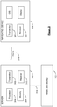
- Figure 8 shows the result of the region scanning at another location.
- the parts of the road network 800 where the heat exceeds the threshold are covered with zones, illustrated as thick lines.
- a first zone extends from point 801 to point 802, and a second zone extends from point 804 to point 805.
- the zones generated from applying the threshold f ⁇ ( x ) > f ⁇ t on the heat map might not be immediately useable, e.g. as they may result in a bad user experience. For example, if a black spot zone of only 1m length or less were to be considered, whilst this 1m might indeed be considered dangerous, it is also true that an approaching vehicle would pass such a zone in virtually no time, so the cumulative likelihood of being involved into an accident while traversing this zone is low. It might also happen that due to limitations of the presentation layer of the device (e.g. a PND, mobile app, etc.), the result of the fusion might need to be optimized for the display. Therefore some post-processing of the results of the initial method might be needed, in order to align the results with additional constraints.
- Typical post-processing actions can be, but are not limited to, discarding (ignoring) regions below a certain length, e.g. 5m, merging regions to close gaps, if the separation is less than e.g. 10m, and enlarging small regions to a desired minimum length, so that if zones are greater than e.g. 5m, but less than e.g. 20m, such zones are extended to a minimum length of e.g. 20m.
- the general algorithm takes only one parameter, which is the heat threshold. This separates areas in which a region should be created from the rest.
- the implementation might, of course, take additional parameters.
- the reference implementation used for accident black spot fusion uses the normal distribution as distribution function and hence takes the standard deviation as an additional parameter that determines the width of the normal distribution.
- the mobile devices 200 may utilise any kind of position sensing technology as an alternative to, or indeed in addition to, GPS.
- the navigation apparatus may utilise other global navigation satellite systems, such as the European Galileo system. Equally, it is not limited to satellite-based systems, but could readily function using ground-based beacons or other kind of system that enables the device to determine its geographic location.
- the example described above is concerned with the incidence of road traffic accidents.
- data concerning other types of event on the road network may be used in addition, to enhance the map.
Description
- The present invention relates to a method and apparatus for creating map data for enhancing a digital map, and is concerned particularly, although not exclusively, with an apparatus and method for creating map data for the enhancement of a digital map to identify zones on segments of a navigable network in which events, such as traffic accidents, are of a high concentration.
- A variety of mobile devices now exist which have the capability of determining their own location. Portable navigation devices (PNDs) that include GNSS (Global Navigation Satellite Systems) signal reception and processing functionality are well known and are widely employed as in-car or other vehicle navigation systems. Such devices include a GNSS antenna, such as a GPS antenna, by means of which satellite-broadcast signals, including location data, can be received and subsequently processed to determine a current location of the device. The device may also include electronic gyroscopes and accelerometers that produce signals that can be processed to determine the current angular and linear acceleration. The determined acceleration may then be used in conjunction with location information derived from the GPS signal to determine the velocity and relative displacement of the device and thus that of a vehicle in which it is mounted. Such sensors are most commonly provided in in-vehicle navigation systems, but may also be provided in the PND itself.
- In recent years, GPS has also been used in systems to warn drivers of the incidence of speed traps, enforcement cameras and road hazards, such as school zones and locations in which there has been a relatively high frequency of accidents, known as "accident black spots". In such systems, a device having a GPS antenna and access to a database containing the location of speed traps, accident black spots and other relevant items is typically provided in a vehicle. The device is configured to provide warnings to a driver when the vehicle, using the location information derived from the GPS signal, is in the vicinity of one of the locations stored in the database. One such system is described, for example, in
WO 01/55744 A2 - However, other systems have also been disclosed. US patent application
US 2012/179363 A1 discloses a navigation system and process for providing a second route to a user of the system when a first route determined by the system passes through an area that has a safety level that is less than a predefined and desired safety level. - US patent application
US2010/250045 A1 discloses vehicle operation diagnosis devices, methods, and programs diagnose a driver's operation of a vehicle based on a vehicle parameter and a driving diagnosis judgment standard that is set for a diagnosis item. The devices, methods, and programs acquire information that pertains to an accident factor for a high-accident location in the vicinity of the vehicle where not less than a specified number of accidents have occurred in the past, modify the driving diagnosis judgment standard based on the accident factor for the high-accident location, in a case where the vehicle is traveling in the high-accident location, and acquire the vehicle parameter. The devices, methods, and programs diagnose the driver's operation of the vehicle based on the modified driving diagnosis judgment standard and the acquired vehicle parameter. - US patent applicaton
US 2002/194016 A1 describes a driving support system provided for guiding a vehicle safely to the desired destination. To this end, use is made of a database of the past traffic accidents owned by an insurance company or public institution. Based on the comparison between the GPS data about the current position of the vehicle and the site data of the past accidents recorded in the database, the driver can be notified, by a warning beep or warning message on the monitor of the navigation system, that his or her vehicle is approaching the site of the past accident on the route. In this manner, though a past accident is now invisible, the driver can be careful in passing by the site where the accident occurred. - Chinese patent application
CN 102411843 A discloses a traffic accident prevention analysis system which is characterised by comprising a traffic accident data acquisition module, a traffic accident database, a GIS geographical information database and a data coupling module. The traffic accident data acquisition module is connected with the traffic accident database, and the traffic accident database and the geographical information database are connected with the data coupling module. According to the invention, geographical information and traffic information are combined, the traffic accident information can be directly displayed on an electrical map, and an accident black spot is obtained through analysis. - Japanese patent application
JP 2012 063360 A - Map data for electronic navigation devices, such as portable navigation devices as described above, comes from specialist map vendors. The data in these maps is specially designed to be used by route guidance algorithms, typically using location data from the GPS system. For example, navigable segments, such as roads, can be described as lines, i.e. vectors (e.g. start point, direction of road, with an entire road being made up of many hundreds of such segments, each uniquely defined by start point/end point direction parameters). A map is then a set of such vectors, data associated with each vector (speed limit; travel direction, etc.), and can further include points of interest (POIs), road names, other geographic features like park boundaries, river boundaries and the like, etc. All map features (e.g. vectors, POIs, etc.) are typically defined in a coordinate system that corresponds with or relates to the GPS coordinate system, enabling a device's position as determined through a GPS system to be located onto the relevant segment shown in a map for an optimal route to be planned to a destination.
- Embodiments of the present invention aim to provide a method and apparatus for the improved notification of so-called accident black spots to a road user.
- According to a first aspect of the present invention there is provided a method according to claim 1.
- In accordance with another aspect of the invention there is provided a computing device according to claim 7.
- In accordance with another aspect of the invention there is provided a computer program product according to claim 9.
- Embodiments of the invention will now be described by way of example only, with reference to the accompanying figures, in which:
-
Figure 1 is a schematic illustration of a Global Positioning System (GPS); -
Figure 2 is a schematic illustration of electronic components arranged to provide a navigation device; -
Figure 3 is a schematic illustration of the manner in which a navigation device may receive information over a wireless communication channel; -
Figure 4 is a perspective view of a navigation device; -
Figure 5 is a schematic representation of a part of a road, showing instances of road traffic accidents; -
Figures 6a and 6b show respectively a continuous heat field representing information about road traffic accidents, and a plurality of regions from the heat field; -
Figure 7 shows schematically an estimated heat map based upon only actual road geometry; and -
Figure 8 illustrates a portion of road network on a display, in which portions of road are shown for which the incidence of traffic accidents is greater than a predetermined threshold. - The present invention is directed to a method and apparatus for creating map data for enhancing a digital map comprising a plurality of segments that are representative of segments of a road network. The created map data are zones representative of accident black spots on the navigable network. The zones may be displayed superposed on a representation of the digital map. Additionally, or alternatively, and in embodiments where the digital map is used by a navigation device, the map data may be used when calculating a route using the digital map or to trigger warnings to a user as they approach, enter and/or leave a zone.
- The map data created in embodiments of the present invention is thus preferably used by mobile devices having location determining means, e.g. a Global Navigation Satellite System (GNSS) receiver such as a GPS receiver, i.e. having the capability of identifying its own location. In the following description, the invention will be described with particular reference to portable navigation devices (PNDs). It should be remembered, however, that the teachings of the present invention are not limited to PNDs but are instead universally applicable to any type of processing device that is configured to warn or alert drivers when they are approaching a location identified as an accident black spot using a local and/or remote database featuring details of such locations. It follows therefore that in the context of the present invention, the mobile devices could be a PND, a navigation device built into a vehicle, or indeed a computing resource (such as a desktop or portable personal computer (PC), mobile telephone or portable digital assistant (PDA)).
-
Figure 1 illustrates an example view of Global Positioning System (GPS), usable by navigation devices. Such systems are known and are used for a variety of purposes. In general, GPS is a satellite-radio based navigation system capable of determining continuous position, velocity, time, and in some instances direction information for an unlimited number of users. Formerly known as NAVSTAR, the GPS incorporates a plurality of satellites that orbit the earth in extremely precise orbits. Based on these precise orbits, GPS satellites can relay their location to any number of receiving units. - The GPS system is implemented when a device, specially equipped to receive GPS data, begins scanning radio frequencies for GPS satellite signals. Upon receiving a radio signal from a GPS satellite, the device determines the precise location of that satellite via one of a plurality of different conventional methods. The device will continue scanning, in most instances, for signals until it has acquired at least three different satellite signals (noting that position is not normally, but can be determined, with only two signals using other triangulation techniques). Implementing geometric triangulation, the receiver utilizes the three known positions to determine its own two-dimensional position relative to the satellites. This can be done in a known manner. Additionally, acquiring a fourth satellite signal will allow the receiving device to calculate its three dimensional position by the same geometrical calculation in a known manner. The position and velocity data can be updated in real time on a continuous basis by an unlimited number of users.
- As shown in
Figure 1 , the GPS system is denoted generally byreference numeral 100. A plurality ofsatellites 102 is in orbit about theearth 104. The orbit of eachsatellite 102 is not necessarily synchronous with the orbits ofother satellites 102 and, in fact, is likely asynchronous. AGPS receiver 106 is shown receiving spread spectrum GPS satellite signals 108 from thevarious satellites 102. - The spread spectrum signals 108, continuously transmitted from each
satellite 102, utilize a highly accurate frequency standard accomplished with an extremely accurate atomic clock. Eachsatellite 102, as part of itsdata signal transmission 108, transmits a data stream indicative of thatparticular satellite 102. It is appreciated by those skilled in the relevant art that theGPS receiver device 106 generally acquires spread spectrum GPS satellite signals 108 from at least threesatellites 102 for theGPS receiver device 106 to calculate its two-dimensional position by triangulation. Acquisition of an additional signal, resulting insignals 108 from a total of foursatellites 102, permits theGPS receiver device 106 to calculate its three-dimensional position in a known manner. -
Figure 2 is an illustrative representation of electronic components of anavigation device 200 according to a preferred embodiment of the present invention, in block component format. It should be noted that the block diagram of thenavigation device 200 is not inclusive of all components of the navigation device, but is only representative of many example components. - The
navigation device 200 is located within a housing (not shown). The housing includes aprocessor 202 connected to aninput device 204 and adisplay screen 206. Theinput device 204 can include a keyboard device, voice input device, touch panel and/or any other known input device utilised to input information; and thedisplay screen 206 can include any type of display screen such as an LCD display, for example. In a particularly preferred arrangement theinput device 204 anddisplay screen 206 are integrated into an integrated input and display device, including a touchpad or touchscreen input so that a user need only touch a portion of thedisplay screen 206 to select one of a plurality of display choices or to activate one of a plurality of virtual buttons. - The
navigation device 200 may include anoutput device 208, for example an audible output device (e.g. a loudspeaker). Asoutput device 208 can produce audible information for a user of thenavigation device 200, it is should equally be understood thatinput device 204 can include a microphone and software for receiving input voice commands as well. - In the
navigation device 200,processor 202 is operatively connected to and set to receive input information frominput device 204 via aconnection 210, and operatively connected to at least one ofdisplay screen 206 andoutput device 208, viaoutput connections 212, to output information thereto. Further, theprocessor 202 is operably coupled to amemory resource 214 viaconnection 216 and is further adapted to receive/send information from/to input/output (I/O)ports 218 viaconnection 220, wherein the I/O port 218 is connectible to an I/O device 222 external to thenavigation device 200. Thememory resource 214 comprises, for example, a volatile memory, such as a Random Access Memory (RAM) and a non-volatile memory, for example a digital memory, such as a flash memory. The external I/O device 222 may include, but is not limited to an external listening device such as an earpiece for example. The connection to I/O device 222 can further be a wired or wireless connection to any other external device such as a car stereo unit for hands-free operation and/or for voice activated operation for example, for connection to an ear piece or head phones, and/or for connection to a mobile phone for example, wherein the mobile phone connection may be used to establish a data connection between thenavigation device 200 and the internet or any other network for example, and/or to establish a connection to a server via the internet or some other network for example. -
Figure 2 further illustrates an operative connection between theprocessor 202 and an antenna/receiver 224 viaconnection 226, wherein the antenna/receiver 224 can be a GPS antenna/receiver for example. It will be understood that the antenna and receiver designated byreference numeral 224 are combined schematically for illustration, but that the antenna and receiver may be separately located components, and that the antenna may be a GPS patch antenna or helical antenna for example. - Further, it will be understood by one of ordinary skill in the art that the electronic components shown in
Figure 2 are powered by power sources (not shown) in a conventional manner. As will be understood by one of ordinary skill in the art, different configurations of the components shown inFigure 2 are considered to be within the scope of the present application. For example, the components shown inFigure 2 may be in communication with one another via wired and/or wireless connections and the like. Thus, the scope of thenavigation device 200 of the present application includes a portable orhandheld navigation device 200. - In addition, the portable or
handheld navigation device 200 ofFigure 2 can be connected or "docked" in a known manner to a vehicle such as a bicycle, a motorbike or a car for example. Such anavigation device 200 is then removable from the docked location for portable or handheld navigation use. As an example,Figure 4 shows anavigation device 200 that may sit on anarm 252, which itself may be secured to a vehicle dashboard, window, etc. using asuction cup 254. Thisarm 252 is one example of a docking station to which thenavigation device 200 can be docked. Thenavigation device 200 can be docked or otherwise connected to thearm 252 of the docking station by snap connecting the navigation device to the arm, for example. To release the connection between thenavigation device 200 and the docking station, a button on thenavigation device 200 may be pressed, for example. Other equally suitable arrangements for coupling and decoupling the navigation device to a docking station are well known to persons of ordinary skill in the art. - Referring now to
Figure 3 , thenavigation device 200 may establish a "mobile" or telecommunications network connection with aserver 302 via a mobile device (not shown) (such as a mobile phone, PDA, and/or any device with mobile phone technology) establishing a digital connection (such as a digital connection via known Bluetooth technology for example). Thereafter, through its network service provider, the mobile device can establish a network connection (through the internet for example) with aserver 302. As such, a "mobile" network connection is established between the navigation device 200 (which can be, and often times is mobile as it travels alone and/or in a vehicle) and theserver 302 to provide a "real-time" or at least very "up to date" gateway for information. - The establishing of the network connection between the mobile device (via a service provider) and another device such as the
server 302, using an internet (such as the World Wide Web) for example, can be done in a known manner. This can include use of TCP/IP layered protocol for example. The mobile device can utilize any number of communication standards such as CDMA, GSM, WAN, etc. - As such, an internet connection may be utilised which is achieved via data connection, via a mobile phone or mobile phone technology within the
navigation device 200 for example. For this connection, an internet connection between theserver 302 and thenavigation device 200 is established. This can be done, for example, through a mobile phone or other mobile device and a GPRS (General Packet Radio Service)-connection (GPRS connection is a high-speed data connection for mobile devices provided by telecom operators; GPRS is a method to connect to the internet). - The
navigation device 200 can further complete a data connection with the mobile device, and eventually with the internet andserver 302, via existing Bluetooth technology for example, in a known manner, wherein the data protocol can utilize any number of standards, such as the GSRM, the Data Protocol Standard for the GSM standard, for example. - The
navigation device 200 may include its own mobile phone technology within thenavigation device 200 itself (including an antenna for example, or optionally using the internal antenna of the navigation device 200). The mobile phone technology within thenavigation device 200 can include internal components as specified above, and/or can include an insertable card (e.g. Subscriber Identity Module or SIM card), complete with necessary mobile phone technology and/or an antenna for example. As such, mobile phone technology within thenavigation device 200 can similarly establish a network connection between thenavigation device 200 and theserver 302, via the internet for example, in a manner similar to that of any mobile device. - For GPRS phone settings, a Bluetooth enabled navigation device may be used to correctly work with the ever-changing spectrum of mobile phone models, manufacturers, etc; model/manufacturer specific settings may be stored on the
navigation device 200, for example. The data stored for this information can be updated. - In
Figure 3 thenavigation device 200 is depicted as being in communication with theserver 302 via ageneric communications channel 318 that can be implemented by any of a number of different arrangements. Theserver 302 and anavigation device 200 can communicate when a connection viacommunications channel 318 is established between theserver 302 and the navigation device 200 (noting that such a connection can be a data connection via mobile device, a direct connection via personal computer via the internet, etc). - The
server 302 includes, in addition to other components which may not be illustrated, aprocessor 304 operatively connected to amemory 306 and further operatively connected, via a wired orwireless connection 314, to a massdata storage device 312. Theprocessor 304 is further operatively connected totransmitter 308 andreceiver 310, to transmit and send information to and fromnavigation device 200 viacommunications channel 318. The signals sent and received may include data, communication, and/or other propagated signals. Thetransmitter 308 andreceiver 310 may be selected or designed according to the communications requirement and communication technology used in the communication design for thenavigation system 200. Further, it should be noted that the functions oftransmitter 308 andreceiver 310 may be combined into a signal transceiver. -
Server 302 is further connected to (or includes) amass storage device 312, noting that themass storage device 312 may be coupled to theserver 302 viacommunication link 314. Themass storage device 312 contains a store of navigation data and map information, and can again be a separate device from theserver 302 or can be incorporated into theserver 302. - The
navigation device 200 is adapted to communicate with theserver 302 throughcommunications channel 318, and includes processor, memory, etc as previously described with regard toFigure 2 , as well astransmitter 320 andreceiver 322 to send and receive signals and/or data through thecommunications channel 318, noting that these devices can further be used to communicate with devices other thanserver 302. Further, thetransmitter 320 andreceiver 322 are selected or designed according to communication requirements and communication technology used in the communication design for thenavigation device 200 and the functions of thetransmitter 320 andreceiver 322 may be combined into a single transceiver. - Software stored in
server memory 306 provides instructions for theprocessor 304 and allows theserver 302 to provide services to thenavigation device 200. One service provided by theserver 302 involves processing requests from thenavigation device 200 and transmitting navigation data from themass data storage 312 to thenavigation device 200. Another service provided by theserver 302 includes processing the navigation data using various algorithms for a desired application and sending the results of these calculations to thenavigation device 200. - The
communication channel 318 generically represents the propagating medium or path that connects thenavigation device 200 and theserver 302. Both theserver 302 andnavigation device 200 include a transmitter for transmitting data through the communication channel and a receiver for receiving data that has been transmitted through the communication channel. - The
communication channel 318 is not limited to a particular communication technology. Additionally, thecommunication channel 318 is not limited to a single communication technology; that is, thechannel 318 may include several communication links that use a variety of technology. For example, thecommunication channel 318 can be adapted to provide a path for electrical, optical, and/or electromagnetic communications, etc. As such, thecommunication channel 318 includes, but is not limited to, one or a combination of the following: electric circuits, electrical conductors such as wires and coaxial cables, fibre optic cables, converters, radio-frequency (RF) waves, the atmosphere, empty space, etc. Furthermore, thecommunication channel 318 can include intermediate devices such as routers, repeaters, buffers, transmitters, and receivers, for example. - In one illustrative arrangement, the
communication channel 318 includes telephone and computer networks. Furthermore, thecommunication channel 318 may be capable of accommodating wireless communication such as radio frequency, microwave frequency, infrared communication, etc. Additionally, thecommunication channel 318 can accommodate satellite communication. - The communication signals transmitted through the
communication channel 318 include, but are not limited to, signals as may be required or desired for given communication technology. For example, the signals may be adapted to be used in cellular communication technology such as Time Division Multiple Access (TDMA), Frequency Division Multiple Access (FDMA), Code Division Multiple Access (CDMA), Global System for Mobile Communications (GSM), etc. Both digital and analogue signals can be transmitted through thecommunication channel 318. These signals may be modulated, encrypted and/or compressed signals as may be desirable for the communication technology. - The
server 302 includes a remote server accessible by thenavigation device 200 via a wireless channel. Theserver 302 may include a network server located on a local area network (LAN), wide area network (WAN), virtual private network (VPN), etc. In other embodiments, theserver 302 may include a personal computer such as a desktop or laptop computer, and thecommunication channel 318 may be a cable connected between the personal computer and thenavigation device 200. Alternatively, a personal computer may be connected between thenavigation device 200 and theserver 302 to establish an internet connection between theserver 302 and thenavigation device 200. Alternatively, a mobile telephone or other handheld device may establish a wireless connection to the internet, for connecting thenavigation device 200 to theserver 302 via the internet. - The
navigation device 200 may be provided with information from theserver 302 via information downloads which may be periodically updated automatically or upon a user connectingnavigation device 200 to theserver 302 and/or may be more dynamic upon a more constant or frequent connection being made between theserver 302 andnavigation device 200 via a wireless mobile connection device and TCP/IP connection for example. For many dynamic calculations, theprocessor 304 in theserver 302 may be used to handle the bulk of the processing needs, however,processor 210 ofnavigation device 200 can also handle much processing and calculation, oftentimes independent of a connection to aserver 302. - As is known in the art, the
navigation device 200 may be configured to provide warnings when a vehicle is approaching a known accident black spot. The warnings may comprise a visual warning on thedisplay 206 of thenavigation device 200, an audible warning, a haptic warning, or any combination thereof as desired. In order to provide such warnings, the navigation device has access to a database of known accident black spots which will typically be stored on thenavigation device 200, e.g. in thememory 214, and will be regularly updated with new data from theserver 302 using thecommunication channel 318. It is envisaged, however, that thenavigation device 200 may only temporary store portions of the database for accident black spots in their immediate vicinity or a planned route. - The accident black spots in the database may each have at least one attribute, and typically a plurality of attributes, associated therewith. The attributes can be, for example: the time of an accident, direction of travel and/or speed of a vehicle involved in an accident, type of vehicle, temperature or other ambient condition.
- The information in the database on the
server 302 needs to be constantly refreshed to ensure that it is accurate and up to date. - In accordance with a non-claimed example, point locations representative of the occurrence of events, in this case accidents on the road network, are obtained from third parties, e.g. from government data. The point locations may just be occurrences of fatal accidents, but they can include all accidents regardless of severity as desired. In accordance with the invention, the point locations are received from user reports transmitted by mobile devices, such as PNDs for example. Such reportsare transmitted automatically from devices in vehicles when an accident is determined to have occurred (e.g. based on vehicle motion sensors). The point locations may have other attributes associated therewith, such as a time of the accident (hour of the day, day of the week, month, season, for example); a driving direction (since some roads may be "dangerous" when travelling in one direction, but not in the other); a driving speed; an ambient condition, such as an external temperature, and so on.
- A digital map comprising a network of navigable segments representing the road network is accessed and the point locations are applied to the digital map. The individual locations are used to generate a heat map, preferably restricted to the network of navigable segments of a digital map, indicating the density of accidents along the network. The distribution function used to generate the heat map may only take into account the geodesic distance, but it may take into account other factors, such as road class, speed limit, average speed for traversing the segment, road surface and the like. Such factors may be known from attributes associated with the point locations, or derived from other sources based on the attributes associated with the point locations. For example, weather and/or temperature information may be obtained for the road at the time of the accident and/or for a period of time before the accident.
- A suitable threshold is applied to the heat map to generate the accident black spot zones. The generated zones are then associated with the appropriate segments of the digital map. The point locations, and therefore the zones, may have one or more attributes associated therewith such as driving direction, weather/temperature, time, and so on, which can be used to determine whether or not warnings are to be provided to a driver.
- There follows a description of one method of creating map data for the enhancement of a digital map of a route network, so that accident black spots may be identified on the map which may be displayed in a mobile navigation device such as a PND, for example, in accordance with an embodiment of the present invention.
- The method uses a technique of heat-map based region fusion, the aim of which is to detect continuous fields that are invisible or impossible to measure directly but can be estimated be integration of multiple single observations.
- Whereas it is usually possible to determine quite precisely where a car accident happened, it is not straightforward to determine directly where roads are dangerous. However, one can expect that accidents happen more often on dangerous roads than anywhere else. On this basis it should be possible to estimate the danger of driving a road by taking the frequency of accidents into account. Accidents on a dangerous road do not necessarily happen at precisely the same spot. For example, a slippery curve may be dangerous along a broad stretch or the road.
-
Figure 5 shows an example of aslippery curve 500 of a road. The hatchedarea 502 is where the centripetal force pulls cars in a perpendicular direction off the road. Whilst the centripetal force cannot itself be seen, over a period it is possible to observe several car accidents happening in the dangerous curve. In the drawing the locations of some of the car accidents are indicated by thefeatures 504. - Integrating local occurrences of accidents over a period reveals the likelihood of a road being dangerous. In the following, a general method will be explained that allows the detection of road stretches having a generic property that manifests itself in point events.
- Regarding
Figure 5 , the road is dangerous in the hatchedarea 502. However, this danger is not visible. It can only be estimated by integrating multiplesingle accidents 504 that happened over a period. In order to determine zones that have increased likelihood of a certain attribute, two main steps are necessary. Firstly, a continuous heat field f̂(x) must be calculated from a discrete point cloud of observations. Every observation distributes its heat in space according to a distribution function K. The distribution function takes only one parameter, which is the distance between the observation xi and any point x in space. The distance metric d determines how the distance between two points is measured. The continuous heat field f̂(x) is defined as follows:
- It should be noted that x can be an element of any n-dimensional space. Implementations might consider, but are not limited to, events that appear in high-dimensional spaces such as geo-coordinates plus time and/or temperature, for example, making the field f̂(x) time and/or temperature dependent. This can be of useful for triggering warnings on roads, but only when the outside temperature is below a certain value. The distribution function describes how a single event distributes its weight in space. The distribution function should be normalized, meaning its integral over the whole space should not be infinite, but rather reflect the actual weight of the event.
- A prominent distribution function is the normal (Gaussian) distribution, but other distributions, such as uniform or triangular, for example, might be applicable as well, depending on the particular use case.
- The reference implementation for accident black spots operates in a 2d-space, even further restricted to the road geometry. It uses normal (Gaussian) distribution as the distribution function and geodesic distance, i.e. "as the crow flies". Other meaningful metrics might include, but are not limited to: driving distance, road speed, road class, road surface, road shape, road angle. External factors can also be considered for real time calculations, e.g. g-forces, weather condition (fog, heavy rain, gales), temperature (icing), etc. The choice of the metric and distribution function depends on the application.
- Since the density f̂(x) will not be evaluated in the whole 2d space, the density estimation is computed on road geometry only, in the example application.
- Calculating the heat map works similarly to the well-known Kernel density estimation with the difference that the heat map does not need to be normalized.
- Once the heat map f̂(x) is calculated, the second step is to detect regions in which the heat exceeds a certain threshold, denoted herein as f̂t . The region(s) are all connected (sub-) spaces in which f̂(x) > f̂t, each connected space becoming one region.
-
Figures 6a and 6b show one example how a continuous heat field is cut into regions.Figure 6a shows an example of the continuous heat field f̂(x).Figure 6b shows the regions 602 - i.e. each connected (sub-) space ofFig 6a , where f̂(x) > f̂t forms one region. - In the example implementation where the space is the road network only, this may be achieved by traversing from junction to junction or dead-end, drawing zones/road stretches where the local heat is larger than the threshold.
-
Figure 7 shows an example of a heat map calculated from threepoints 702 representing known accidents; each being shown by a danger icon. Some portions of the road network are shown in thicksolid lines 710, others in thinsolid lines 711 and yet others indotted lines 712. Thedotted lines 712 depict areas on the road network having a low value of the heat field; the thinsolid lines 711 depict areas having an intermediate value of the heat field; and the thinksolid lines 710 depict areas having a high value of the heat field. Given that the point observations are accidents, thehigh density areas 710 have a higher likelihood of being dangerous than either theintermediate density areas 711 or thelow density areas 712. Setting the threshold to high density areas only would result in four zones covering the whole junction, when approached from all different driving directions, implementation can consider obeying the driving direction on involved stretches of the road (or omit it if desired). Alternatively an area can be defined as a square or elliptical shape that alerts any drivers entering the area. If the threshold were to be set at intermediate density levels, there would be more resulting zones, for example also in the opposite lane. The choice of the heat threshold is one of the main tuning parameters that toggles the sensitivity of the region detection and hence the length and number of created zones. -
Figure 8 shows the result of the region scanning at another location. The parts of theroad network 800 where the heat exceeds the threshold are covered with zones, illustrated as thick lines. A first zone extends frompoint 801 to point 802, and a second zone extends frompoint 804 topoint 805. - The zones generated from applying the threshold f̂(x) > f̂t on the heat map might not be immediately useable, e.g. as they may result in a bad user experience. For example, if a black spot zone of only 1m length or less were to be considered, whilst this 1m might indeed be considered dangerous, it is also true that an approaching vehicle would pass such a zone in virtually no time, so the cumulative likelihood of being involved into an accident while traversing this zone is low. It might also happen that due to limitations of the presentation layer of the device (e.g. a PND, mobile app, etc.), the result of the fusion might need to be optimized for the display. Therefore some post-processing of the results of the initial method might be needed, in order to align the results with additional constraints. Typical post-processing actions can be, but are not limited to, discarding (ignoring) regions below a certain length, e.g. 5m, merging regions to close gaps, if the separation is less than e.g. 10m, and enlarging small regions to a desired minimum length, so that if zones are greater than e.g. 5m, but less than e.g. 20m, such zones are extended to a minimum length of e.g. 20m.
- The general algorithm takes only one parameter, which is the heat threshold. This separates areas in which a region should be created from the rest. The implementation might, of course, take additional parameters. The reference implementation used for accident black spot fusion uses the normal distribution as distribution function and hence takes the standard deviation as an additional parameter that determines the width of the normal distribution.
- It will be appreciated that whilst various aspects and embodiments of the present invention have heretofore been described, the scope of the present invention is not limited to the particular arrangements set out herein; rather it is defined by the appended claims.
- Whilst embodiments described in the foregoing detailed description refer to GPS, it should be noted that the
mobile devices 200, e.g. navigation apparatus, may utilise any kind of position sensing technology as an alternative to, or indeed in addition to, GPS. For example, the navigation apparatus may utilise other global navigation satellite systems, such as the European Galileo system. Equally, it is not limited to satellite-based systems, but could readily function using ground-based beacons or other kind of system that enables the device to determine its geographic location. - The example described above is concerned with the incidence of road traffic accidents. However, data concerning other types of event on the road network may be used in addition, to enhance the map.
- It will also be well understood by persons of ordinary skill in the art that whilst the preferred embodiment may implement certain functionality by means of software, that functionality could equally be implemented solely in hardware (for example by means of one or more SICs (application specific integrated circuit)) or indeed by a mix of hardware and software.
Claims (10)
- A computer-implemented method of creating map data for enhancing a digital map comprising a plurality of navigable segments representing a road network (800) of navigable segments, the method comprising:obtaining point locations of the digital map which correspond to individual events on the network, the individual events being representative of occurrences of traffic accidents (504, 702);generating a further map representing the concentrations of events;applying a threshold calculation to the further map to identify one or more zones on the road network having a high concentration of events (502, 602, 710); andassociating each of the one or more zones with at least one segment in the digital map, characterised in that data of point locations is collected from reports received from road users, wherein the reports are arranged to be received as automatic transmissions from mobile devices (200) in vehicles that have been involved in an accident, and in that the further map is a heat map generated in accordance with a selected distribution function.
- The method according to claim 1, wherein the step of associating each of the one or more zones with at least one segment comprises associating zone location information with the segment, so as to indicate the location of the zone within the segment.
- The method according to claim 1 or 2, wherein the data of point locations have one or more attributes including, but not limited to: the time of the accident (504), direction of travel, speed of a vehicle involved in an accident, type of vehicle, temperature or other ambient condition.
- The method according to claim 3, wherein the method includes associating at least one of the one or more attributes to each of the one or more zones.
- The method according to any preceding claim, wherein the method further comprises applying further processing to data related to the zones.
- The method according to claim 5, wherein the further processing includes one or more of: discarding zones below a certain size, merging zones that are below a threshold proximity of each other, and enlarging zones to a minimum size.
- A computing device, comprising:a memory storing a digital map comprising a plurality of segments representing a road network (800) of navigable segments; anda processor operatively arranged to access the digital map and to:obtain point locations of the digital map which correspond to individual events on the network, the individual events being representative of occurrences of traffic accidents (504, 702);generate a further map representing the concentrations of events ;apply a threshold calculation to the further heat map to identify one or more zones on the road network having a high concentration of events (502, 602, 710); andassociate each of the one or more zones with at least one segment in the digital map, characterised in that data of point locations is collected from reports received from road users, wherein the reports are arranged to be received as automatic transmissions from mobile devices (200) in vehicles that have been involved in an accident, and in that the further map is a heat map generated in accordance with a selected distribution function.
- The computing device of claim 7, wherein the computing device comprises a server system (302) arranged to process data for the maintenance of a database containing the geographic location of events, the server system comprising communication means for receiving the reports from the mobile devices (200), the mobile devices having location determining means, the reports each comprising at least geographical location data of an event.
- A computer program product comprising computer program code arranged in use to perform a method according to any of claims 1 to 6, when said computer program code is run on a computer.
- The computer program product according to claim 9 embodied on a computer readable medium.
Applications Claiming Priority (2)
| Application Number | Priority Date | Filing Date | Title |
|---|---|---|---|
| GBGB1300901.4A GB201300901D0 (en) | 2013-01-18 | 2013-01-18 | Method and apparatus for creating map data |
| PCT/EP2014/050936 WO2014111537A1 (en) | 2013-01-18 | 2014-01-17 | Method and apparatus for creating map data |
Publications (2)
| Publication Number | Publication Date |
|---|---|
| EP2946168A1 EP2946168A1 (en) | 2015-11-25 |
| EP2946168B1 true EP2946168B1 (en) | 2019-04-17 |
Family
ID=47843535
Family Applications (1)
| Application Number | Title | Priority Date | Filing Date |
|---|---|---|---|
| EP14700747.0A Active EP2946168B1 (en) | 2013-01-18 | 2014-01-17 | Method and apparatus for creating map data |
Country Status (5)
| Country | Link |
|---|---|
| US (1) | US9846053B2 (en) |
| EP (1) | EP2946168B1 (en) |
| CN (1) | CN105008860B (en) |
| GB (1) | GB201300901D0 (en) |
| WO (1) | WO2014111537A1 (en) |
Families Citing this family (17)
| Publication number | Priority date | Publication date | Assignee | Title |
|---|---|---|---|---|
| GB2507104A (en) | 2012-10-19 | 2014-04-23 | Nicoventures Holdings Ltd | Electronic inhalation device |
| US10024684B2 (en) * | 2014-12-02 | 2018-07-17 | Operr Technologies, Inc. | Method and system for avoidance of accidents |
| GB201517089D0 (en) * | 2015-09-28 | 2015-11-11 | Nicoventures Holdings Ltd | Vaping heat map system and method for electronic vapour provision systems |
| FR3045910B1 (en) * | 2015-12-22 | 2018-01-05 | Bull Sas | METHOD FOR SIGNALING AN ACCIDENT BY A SIGNALING DRONE |
| CN105741550B (en) * | 2016-04-19 | 2018-10-26 | 武汉大学 | A kind of cyberspace line feature Density Estimator method |
| KR20180039892A (en) * | 2016-10-11 | 2018-04-19 | 현대자동차주식회사 | Navigation apparatus, vehicle comprising the same and control method of the vehicle |
| IT201600115888A1 (en) * | 2016-11-16 | 2018-05-16 | Roberto Bini | METHOD AND DYNAMIC CONTROL SYSTEM OF SAFETY OF TRAINS IN SINGLE TRACK |
| IT201700016359A1 (en) * | 2017-02-14 | 2018-08-14 | Soluzioni Ingegneria S R L | Collaborative driving aid |
| CN109493600B (en) * | 2018-11-21 | 2021-02-05 | 合肥工业大学 | Traffic accident frequent road section identification method based on accident risk degree |
| US11307039B2 (en) * | 2019-06-12 | 2022-04-19 | GM Global Technology Operations LLC | Combining heterogeneous types of maps |
| CN111126713B (en) * | 2019-12-31 | 2023-05-09 | 方正国际软件(北京)有限公司 | Space-time hot spot prediction method and device based on bayonet data and controller |
| US11718288B2 (en) | 2020-03-23 | 2023-08-08 | Toyota Motor North America, Inc. | Consensus-based transport event severity |
| US11574543B2 (en) * | 2020-03-23 | 2023-02-07 | Toyota Motor North America, Inc. | Transport dangerous location warning |
| CN112013835B (en) * | 2020-09-21 | 2022-08-26 | 珠海格力智能装备有限公司 | Map device, navigation vehicle, server, storage medium, navigation system, and navigation method |
| US11365980B1 (en) * | 2020-12-18 | 2022-06-21 | Samsara Inc. | Vehicle gateway device and interactive map graphical user interfaces associated therewith |
| WO2024014001A1 (en) * | 2022-07-15 | 2024-01-18 | 日本電信電話株式会社 | Detection device, detection method, and detection program |
| WO2024014000A1 (en) * | 2022-07-15 | 2024-01-18 | 日本電信電話株式会社 | Detection device, detection method, and detection program |
Family Cites Families (14)
| Publication number | Priority date | Publication date | Assignee | Title |
|---|---|---|---|---|
| GB2365643B (en) | 2000-01-26 | 2002-04-10 | Origin Technologies Ltd | Speed trap detection and warning system |
| WO2002050794A1 (en) | 2000-12-21 | 2002-06-27 | Kabushiki Kaisha Toshiba | Traffic accident warning information providing system,traffic accident warning information providing site and navigation device |
| JP3866532B2 (en) * | 2001-06-13 | 2007-01-10 | 富士通株式会社 | Mobile object safe operation support apparatus and computer program |
| CA2646830A1 (en) * | 2006-06-27 | 2008-01-03 | Tomtom International B.V. | Navigation device and method for providing warnings for a speed trap |
| JP4990077B2 (en) | 2007-09-14 | 2012-08-01 | 株式会社日立製作所 | Navigation device |
| JP4849148B2 (en) * | 2009-03-30 | 2012-01-11 | アイシン・エィ・ダブリュ株式会社 | Vehicle operation diagnosis device, vehicle operation diagnosis method, and computer program |
| US8694241B1 (en) * | 2010-10-05 | 2014-04-08 | Google Inc. | Visualization of traffic patterns using GPS data |
| US20120179363A1 (en) * | 2011-01-06 | 2012-07-12 | Toyota Motor Engineering & Manufacturing North America, Inc. | Route calculation and guidance with consideration of safety |
| GB2488349B (en) * | 2011-02-23 | 2020-04-22 | Buddi Ltd | Location data analysis |
| JP5641545B2 (en) | 2011-02-23 | 2014-12-17 | 株式会社日本製鋼所 | Thin film surface inspection method and inspection apparatus |
| CN102411843A (en) | 2011-09-21 | 2012-04-11 | 中盟智能科技(苏州)有限公司 | Traffic accident prevention analysis system |
| JP5009433B2 (en) | 2011-11-10 | 2012-08-22 | 株式会社野村総合研究所 | Navigation device, route search method, and computer program |
| CN102564429A (en) * | 2011-12-28 | 2012-07-11 | 深圳市凯立德科技股份有限公司 | Method and device for traffic information navigation |
| CN102881182B (en) * | 2012-11-01 | 2016-01-13 | 深圳市凯立德科技股份有限公司 | A kind of traffic information display method and device thereof |
-
2013
- 2013-01-18 GB GBGB1300901.4A patent/GB201300901D0/en not_active Ceased
-
2014
- 2014-01-17 WO PCT/EP2014/050936 patent/WO2014111537A1/en active Application Filing
- 2014-01-17 EP EP14700747.0A patent/EP2946168B1/en active Active
- 2014-01-17 CN CN201480009817.3A patent/CN105008860B/en active Active
- 2014-01-17 US US14/761,650 patent/US9846053B2/en active Active
Non-Patent Citations (1)
| Title |
|---|
| None * |
Also Published As
| Publication number | Publication date |
|---|---|
| EP2946168A1 (en) | 2015-11-25 |
| GB201300901D0 (en) | 2013-03-06 |
| WO2014111537A1 (en) | 2014-07-24 |
| CN105008860A (en) | 2015-10-28 |
| CN105008860B (en) | 2018-10-19 |
| US9846053B2 (en) | 2017-12-19 |
| US20150338235A1 (en) | 2015-11-26 |
Similar Documents
| Publication | Publication Date | Title |
|---|---|---|
| EP2946168B1 (en) | Method and apparatus for creating map data | |
| US10346372B2 (en) | Point of interest database maintenance system | |
| EP3341687B1 (en) | Methods and systems for generating routes | |
| EP2898292B1 (en) | Method and system for determining a deviation in the course of a navigable stretch | |
| EP2867877B1 (en) | Location estimation method and system | |
| EP2674722B1 (en) | Method of determining a deviation from expected jam conditions | |
| EP2890955B1 (en) | Method and apparatus for predicting destinations | |
| US10458804B2 (en) | Methods of obtaining and using point of interest data | |
| US9847024B2 (en) | Methods and systems for providing a traffic congestion warning | |
| KR102132958B1 (en) | Methods of providing traffic flow messages | |
| EP3214610A1 (en) | Method for associating a hazard with a zone of a digital map | |
| WO2017089600A1 (en) | Methods and systems for generating routes to optimise traffic flow |
Legal Events
| Date | Code | Title | Description |
|---|---|---|---|
| PUAI | Public reference made under article 153(3) epc to a published international application that has entered the european phase |
Free format text: ORIGINAL CODE: 0009012 |
|
| 17P | Request for examination filed |
Effective date: 20150818 |
|
| AK | Designated contracting states |
Kind code of ref document: A1 Designated state(s): AL AT BE BG CH CY CZ DE DK EE ES FI FR GB GR HR HU IE IS IT LI LT LU LV MC MK MT NL NO PL PT RO RS SE SI SK SM TR |
|
| AX | Request for extension of the european patent |
Extension state: BA ME |
|
| DAX | Request for extension of the european patent (deleted) | ||
| STAA | Information on the status of an ep patent application or granted ep patent |
Free format text: STATUS: EXAMINATION IS IN PROGRESS |
|
| 17Q | First examination report despatched |
Effective date: 20180125 |
|
| RAP1 | Party data changed (applicant data changed or rights of an application transferred) |
Owner name: TOMTOM TRAFFIC B.V. |
|
| GRAP | Despatch of communication of intention to grant a patent |
Free format text: ORIGINAL CODE: EPIDOSNIGR1 |
|
| STAA | Information on the status of an ep patent application or granted ep patent |
Free format text: STATUS: GRANT OF PATENT IS INTENDED |
|
| INTG | Intention to grant announced |
Effective date: 20181102 |
|
| GRAS | Grant fee paid |
Free format text: ORIGINAL CODE: EPIDOSNIGR3 |
|
| GRAA | (expected) grant |
Free format text: ORIGINAL CODE: 0009210 |
|
| STAA | Information on the status of an ep patent application or granted ep patent |
Free format text: STATUS: THE PATENT HAS BEEN GRANTED |
|
| AK | Designated contracting states |
Kind code of ref document: B1 Designated state(s): AL AT BE BG CH CY CZ DE DK EE ES FI FR GB GR HR HU IE IS IT LI LT LU LV MC MK MT NL NO PL PT RO RS SE SI SK SM TR |
|
| REG | Reference to a national code |
Ref country code: GB Ref legal event code: FG4D |
|
| REG | Reference to a national code |
Ref country code: CH Ref legal event code: EP |
|
| REG | Reference to a national code |
Ref country code: DE Ref legal event code: R096 Ref document number: 602014044843 Country of ref document: DE |
|
| REG | Reference to a national code |
Ref country code: AT Ref legal event code: REF Ref document number: 1122047 Country of ref document: AT Kind code of ref document: T Effective date: 20190515 Ref country code: IE Ref legal event code: FG4D |
|
| REG | Reference to a national code |
Ref country code: NL Ref legal event code: FP |
|
| REG | Reference to a national code |
Ref country code: LT Ref legal event code: MG4D |
|
| PG25 | Lapsed in a contracting state [announced via postgrant information from national office to epo] |
Ref country code: AL Free format text: LAPSE BECAUSE OF FAILURE TO SUBMIT A TRANSLATION OF THE DESCRIPTION OR TO PAY THE FEE WITHIN THE PRESCRIBED TIME-LIMIT Effective date: 20190417 Ref country code: PT Free format text: LAPSE BECAUSE OF FAILURE TO SUBMIT A TRANSLATION OF THE DESCRIPTION OR TO PAY THE FEE WITHIN THE PRESCRIBED TIME-LIMIT Effective date: 20190817 Ref country code: ES Free format text: LAPSE BECAUSE OF FAILURE TO SUBMIT A TRANSLATION OF THE DESCRIPTION OR TO PAY THE FEE WITHIN THE PRESCRIBED TIME-LIMIT Effective date: 20190417 Ref country code: SE Free format text: LAPSE BECAUSE OF FAILURE TO SUBMIT A TRANSLATION OF THE DESCRIPTION OR TO PAY THE FEE WITHIN THE PRESCRIBED TIME-LIMIT Effective date: 20190417 Ref country code: HR Free format text: LAPSE BECAUSE OF FAILURE TO SUBMIT A TRANSLATION OF THE DESCRIPTION OR TO PAY THE FEE WITHIN THE PRESCRIBED TIME-LIMIT Effective date: 20190417 Ref country code: NO Free format text: LAPSE BECAUSE OF FAILURE TO SUBMIT A TRANSLATION OF THE DESCRIPTION OR TO PAY THE FEE WITHIN THE PRESCRIBED TIME-LIMIT Effective date: 20190717 Ref country code: FI Free format text: LAPSE BECAUSE OF FAILURE TO SUBMIT A TRANSLATION OF THE DESCRIPTION OR TO PAY THE FEE WITHIN THE PRESCRIBED TIME-LIMIT Effective date: 20190417 Ref country code: LT Free format text: LAPSE BECAUSE OF FAILURE TO SUBMIT A TRANSLATION OF THE DESCRIPTION OR TO PAY THE FEE WITHIN THE PRESCRIBED TIME-LIMIT Effective date: 20190417 |
|
| PG25 | Lapsed in a contracting state [announced via postgrant information from national office to epo] |
Ref country code: RS Free format text: LAPSE BECAUSE OF FAILURE TO SUBMIT A TRANSLATION OF THE DESCRIPTION OR TO PAY THE FEE WITHIN THE PRESCRIBED TIME-LIMIT Effective date: 20190417 Ref country code: LV Free format text: LAPSE BECAUSE OF FAILURE TO SUBMIT A TRANSLATION OF THE DESCRIPTION OR TO PAY THE FEE WITHIN THE PRESCRIBED TIME-LIMIT Effective date: 20190417 Ref country code: PL Free format text: LAPSE BECAUSE OF FAILURE TO SUBMIT A TRANSLATION OF THE DESCRIPTION OR TO PAY THE FEE WITHIN THE PRESCRIBED TIME-LIMIT Effective date: 20190417 Ref country code: BG Free format text: LAPSE BECAUSE OF FAILURE TO SUBMIT A TRANSLATION OF THE DESCRIPTION OR TO PAY THE FEE WITHIN THE PRESCRIBED TIME-LIMIT Effective date: 20190717 Ref country code: GR Free format text: LAPSE BECAUSE OF FAILURE TO SUBMIT A TRANSLATION OF THE DESCRIPTION OR TO PAY THE FEE WITHIN THE PRESCRIBED TIME-LIMIT Effective date: 20190718 |
|
| REG | Reference to a national code |
Ref country code: AT Ref legal event code: MK05 Ref document number: 1122047 Country of ref document: AT Kind code of ref document: T Effective date: 20190417 |
|
| PG25 | Lapsed in a contracting state [announced via postgrant information from national office to epo] |
Ref country code: IS Free format text: LAPSE BECAUSE OF FAILURE TO SUBMIT A TRANSLATION OF THE DESCRIPTION OR TO PAY THE FEE WITHIN THE PRESCRIBED TIME-LIMIT Effective date: 20190817 |
|
| REG | Reference to a national code |
Ref country code: DE Ref legal event code: R097 Ref document number: 602014044843 Country of ref document: DE |
|
| PG25 | Lapsed in a contracting state [announced via postgrant information from national office to epo] |
Ref country code: DK Free format text: LAPSE BECAUSE OF FAILURE TO SUBMIT A TRANSLATION OF THE DESCRIPTION OR TO PAY THE FEE WITHIN THE PRESCRIBED TIME-LIMIT Effective date: 20190417 Ref country code: SK Free format text: LAPSE BECAUSE OF FAILURE TO SUBMIT A TRANSLATION OF THE DESCRIPTION OR TO PAY THE FEE WITHIN THE PRESCRIBED TIME-LIMIT Effective date: 20190417 Ref country code: EE Free format text: LAPSE BECAUSE OF FAILURE TO SUBMIT A TRANSLATION OF THE DESCRIPTION OR TO PAY THE FEE WITHIN THE PRESCRIBED TIME-LIMIT Effective date: 20190417 Ref country code: CZ Free format text: LAPSE BECAUSE OF FAILURE TO SUBMIT A TRANSLATION OF THE DESCRIPTION OR TO PAY THE FEE WITHIN THE PRESCRIBED TIME-LIMIT Effective date: 20190417 Ref country code: AT Free format text: LAPSE BECAUSE OF FAILURE TO SUBMIT A TRANSLATION OF THE DESCRIPTION OR TO PAY THE FEE WITHIN THE PRESCRIBED TIME-LIMIT Effective date: 20190417 Ref country code: RO Free format text: LAPSE BECAUSE OF FAILURE TO SUBMIT A TRANSLATION OF THE DESCRIPTION OR TO PAY THE FEE WITHIN THE PRESCRIBED TIME-LIMIT Effective date: 20190417 |
|
| PLBE | No opposition filed within time limit |
Free format text: ORIGINAL CODE: 0009261 |
|
| STAA | Information on the status of an ep patent application or granted ep patent |
Free format text: STATUS: NO OPPOSITION FILED WITHIN TIME LIMIT |
|
| PG25 | Lapsed in a contracting state [announced via postgrant information from national office to epo] |
Ref country code: IT Free format text: LAPSE BECAUSE OF FAILURE TO SUBMIT A TRANSLATION OF THE DESCRIPTION OR TO PAY THE FEE WITHIN THE PRESCRIBED TIME-LIMIT Effective date: 20190417 Ref country code: SM Free format text: LAPSE BECAUSE OF FAILURE TO SUBMIT A TRANSLATION OF THE DESCRIPTION OR TO PAY THE FEE WITHIN THE PRESCRIBED TIME-LIMIT Effective date: 20190417 |
|
| 26N | No opposition filed |
Effective date: 20200120 |
|
| PG25 | Lapsed in a contracting state [announced via postgrant information from national office to epo] |
Ref country code: TR Free format text: LAPSE BECAUSE OF FAILURE TO SUBMIT A TRANSLATION OF THE DESCRIPTION OR TO PAY THE FEE WITHIN THE PRESCRIBED TIME-LIMIT Effective date: 20190417 |
|
| PG25 | Lapsed in a contracting state [announced via postgrant information from national office to epo] |
Ref country code: SI Free format text: LAPSE BECAUSE OF FAILURE TO SUBMIT A TRANSLATION OF THE DESCRIPTION OR TO PAY THE FEE WITHIN THE PRESCRIBED TIME-LIMIT Effective date: 20190417 |
|
| PG25 | Lapsed in a contracting state [announced via postgrant information from national office to epo] |
Ref country code: MC Free format text: LAPSE BECAUSE OF FAILURE TO SUBMIT A TRANSLATION OF THE DESCRIPTION OR TO PAY THE FEE WITHIN THE PRESCRIBED TIME-LIMIT Effective date: 20190417 |
|
| REG | Reference to a national code |
Ref country code: CH Ref legal event code: PL |
|
| REG | Reference to a national code |
Ref country code: BE Ref legal event code: MM Effective date: 20200131 |
|
| PG25 | Lapsed in a contracting state [announced via postgrant information from national office to epo] |
Ref country code: LU Free format text: LAPSE BECAUSE OF NON-PAYMENT OF DUE FEES Effective date: 20200117 |
|
| PG25 | Lapsed in a contracting state [announced via postgrant information from national office to epo] |
Ref country code: BE Free format text: LAPSE BECAUSE OF NON-PAYMENT OF DUE FEES Effective date: 20200131 Ref country code: CH Free format text: LAPSE BECAUSE OF NON-PAYMENT OF DUE FEES Effective date: 20200131 Ref country code: LI Free format text: LAPSE BECAUSE OF NON-PAYMENT OF DUE FEES Effective date: 20200131 |
|
| PG25 | Lapsed in a contracting state [announced via postgrant information from national office to epo] |
Ref country code: IE Free format text: LAPSE BECAUSE OF NON-PAYMENT OF DUE FEES Effective date: 20200117 |
|
| PG25 | Lapsed in a contracting state [announced via postgrant information from national office to epo] |
Ref country code: MT Free format text: LAPSE BECAUSE OF FAILURE TO SUBMIT A TRANSLATION OF THE DESCRIPTION OR TO PAY THE FEE WITHIN THE PRESCRIBED TIME-LIMIT Effective date: 20190417 Ref country code: CY Free format text: LAPSE BECAUSE OF FAILURE TO SUBMIT A TRANSLATION OF THE DESCRIPTION OR TO PAY THE FEE WITHIN THE PRESCRIBED TIME-LIMIT Effective date: 20190417 |
|
| PG25 | Lapsed in a contracting state [announced via postgrant information from national office to epo] |
Ref country code: MK Free format text: LAPSE BECAUSE OF FAILURE TO SUBMIT A TRANSLATION OF THE DESCRIPTION OR TO PAY THE FEE WITHIN THE PRESCRIBED TIME-LIMIT Effective date: 20190417 |
|
| PGFP | Annual fee paid to national office [announced via postgrant information from national office to epo] |
Ref country code: DE Payment date: 20221207 Year of fee payment: 10 |
|
| P01 | Opt-out of the competence of the unified patent court (upc) registered |
Effective date: 20230520 |
|
| PGFP | Annual fee paid to national office [announced via postgrant information from national office to epo] |
Ref country code: GB Payment date: 20231207 Year of fee payment: 11 |
|
| PGFP | Annual fee paid to national office [announced via postgrant information from national office to epo] |
Ref country code: NL Payment date: 20231215 Year of fee payment: 11 Ref country code: FR Payment date: 20231222 Year of fee payment: 11 |