EP2946143B1 - Pressure relief valve with rotating damper - Google Patents
Pressure relief valve with rotating damper Download PDFInfo
- Publication number
- EP2946143B1 EP2946143B1 EP14702709.8A EP14702709A EP2946143B1 EP 2946143 B1 EP2946143 B1 EP 2946143B1 EP 14702709 A EP14702709 A EP 14702709A EP 2946143 B1 EP2946143 B1 EP 2946143B1
- Authority
- EP
- European Patent Office
- Prior art keywords
- valve body
- valve
- axis
- outlet
- pressure
- Prior art date
- Legal status (The legal status is an assumption and is not a legal conclusion. Google has not performed a legal analysis and makes no representation as to the accuracy of the status listed.)
- Not-in-force
Links
- 230000004044 response Effects 0.000 claims description 23
- 238000000034 method Methods 0.000 claims description 21
- 230000007423 decrease Effects 0.000 claims description 6
- 230000001105 regulatory effect Effects 0.000 claims description 5
- 238000007599 discharging Methods 0.000 claims 1
- 239000007789 gas Substances 0.000 description 56
- 238000005336 cracking Methods 0.000 description 8
- 238000010586 diagram Methods 0.000 description 5
- 238000006073 displacement reaction Methods 0.000 description 5
- 239000002912 waste gas Substances 0.000 description 4
- 230000008569 process Effects 0.000 description 3
- 230000009467 reduction Effects 0.000 description 2
- 230000001133 acceleration Effects 0.000 description 1
- 238000004590 computer program Methods 0.000 description 1
- 230000000694 effects Effects 0.000 description 1
- 230000007613 environmental effect Effects 0.000 description 1
- 239000012530 fluid Substances 0.000 description 1
- 239000000463 material Substances 0.000 description 1
- 230000007704 transition Effects 0.000 description 1
- 239000002699 waste material Substances 0.000 description 1
Images



Classifications
-
- F—MECHANICAL ENGINEERING; LIGHTING; HEATING; WEAPONS; BLASTING
- F16—ENGINEERING ELEMENTS AND UNITS; GENERAL MEASURES FOR PRODUCING AND MAINTAINING EFFECTIVE FUNCTIONING OF MACHINES OR INSTALLATIONS; THERMAL INSULATION IN GENERAL
- F16K—VALVES; TAPS; COCKS; ACTUATING-FLOATS; DEVICES FOR VENTING OR AERATING
- F16K17/00—Safety valves; Equalising valves, e.g. pressure relief valves
- F16K17/02—Safety valves; Equalising valves, e.g. pressure relief valves opening on surplus pressure on one side; closing on insufficient pressure on one side
- F16K17/04—Safety valves; Equalising valves, e.g. pressure relief valves opening on surplus pressure on one side; closing on insufficient pressure on one side spring-loaded
- F16K17/0433—Safety valves; Equalising valves, e.g. pressure relief valves opening on surplus pressure on one side; closing on insufficient pressure on one side spring-loaded with vibration preventing means
-
- F—MECHANICAL ENGINEERING; LIGHTING; HEATING; WEAPONS; BLASTING
- F16—ENGINEERING ELEMENTS AND UNITS; GENERAL MEASURES FOR PRODUCING AND MAINTAINING EFFECTIVE FUNCTIONING OF MACHINES OR INSTALLATIONS; THERMAL INSULATION IN GENERAL
- F16K—VALVES; TAPS; COCKS; ACTUATING-FLOATS; DEVICES FOR VENTING OR AERATING
- F16K17/00—Safety valves; Equalising valves, e.g. pressure relief valves
- F16K17/02—Safety valves; Equalising valves, e.g. pressure relief valves opening on surplus pressure on one side; closing on insufficient pressure on one side
- F16K17/12—Safety valves; Equalising valves, e.g. pressure relief valves opening on surplus pressure on one side; closing on insufficient pressure on one side weight-loaded
-
- F—MECHANICAL ENGINEERING; LIGHTING; HEATING; WEAPONS; BLASTING
- F16—ENGINEERING ELEMENTS AND UNITS; GENERAL MEASURES FOR PRODUCING AND MAINTAINING EFFECTIVE FUNCTIONING OF MACHINES OR INSTALLATIONS; THERMAL INSULATION IN GENERAL
- F16K—VALVES; TAPS; COCKS; ACTUATING-FLOATS; DEVICES FOR VENTING OR AERATING
- F16K29/00—Arrangements for movement of valve members other than for opening and closing the valve, e.g. for grinding-in, for preventing sticking
-
- F—MECHANICAL ENGINEERING; LIGHTING; HEATING; WEAPONS; BLASTING
- F16—ENGINEERING ELEMENTS AND UNITS; GENERAL MEASURES FOR PRODUCING AND MAINTAINING EFFECTIVE FUNCTIONING OF MACHINES OR INSTALLATIONS; THERMAL INSULATION IN GENERAL
- F16L—PIPES; JOINTS OR FITTINGS FOR PIPES; SUPPORTS FOR PIPES, CABLES OR PROTECTIVE TUBING; MEANS FOR THERMAL INSULATION IN GENERAL
- F16L55/00—Devices or appurtenances for use in, or in connection with, pipes or pipe systems
- F16L55/04—Devices damping pulsations or vibrations in fluids
-
- F—MECHANICAL ENGINEERING; LIGHTING; HEATING; WEAPONS; BLASTING
- F23—COMBUSTION APPARATUS; COMBUSTION PROCESSES
- F23G—CREMATION FURNACES; CONSUMING WASTE PRODUCTS BY COMBUSTION
- F23G7/00—Incinerators or other apparatus for consuming industrial waste, e.g. chemicals
- F23G7/06—Incinerators or other apparatus for consuming industrial waste, e.g. chemicals of waste gases or noxious gases, e.g. exhaust gases
- F23G7/08—Incinerators or other apparatus for consuming industrial waste, e.g. chemicals of waste gases or noxious gases, e.g. exhaust gases using flares, e.g. in stacks
-
- F—MECHANICAL ENGINEERING; LIGHTING; HEATING; WEAPONS; BLASTING
- F23—COMBUSTION APPARATUS; COMBUSTION PROCESSES
- F23G—CREMATION FURNACES; CONSUMING WASTE PRODUCTS BY COMBUSTION
- F23G7/00—Incinerators or other apparatus for consuming industrial waste, e.g. chemicals
- F23G7/06—Incinerators or other apparatus for consuming industrial waste, e.g. chemicals of waste gases or noxious gases, e.g. exhaust gases
- F23G7/08—Incinerators or other apparatus for consuming industrial waste, e.g. chemicals of waste gases or noxious gases, e.g. exhaust gases using flares, e.g. in stacks
- F23G7/085—Incinerators or other apparatus for consuming industrial waste, e.g. chemicals of waste gases or noxious gases, e.g. exhaust gases using flares, e.g. in stacks in stacks
-
- F—MECHANICAL ENGINEERING; LIGHTING; HEATING; WEAPONS; BLASTING
- F23—COMBUSTION APPARATUS; COMBUSTION PROCESSES
- F23N—REGULATING OR CONTROLLING COMBUSTION
- F23N2235/00—Valves, nozzles or pumps
- F23N2235/12—Fuel valves
- F23N2235/24—Valve details
Definitions
- waste gasses are disposed of using a flare stack burner.
- a flare tip comprising a valve body, such as a Coanda body, that is either free floating or spring-loaded against an outlet or valve seat of a gas pipe. Pressurized waste gas lifts the valve body off the valve seat to form a variable opening through which the waste gas is discharged and ignited by a pilot burner to dispose of the waste gas.
- the exit velocity of the gas through the variable opening changes in response to the displacement of the valve body off the valve seat. This occurs due to the variable load applied to the valve body by the spring. As pressure increases, the valve body is displaced further from the valve seat.
- exit velocity of the gas past the spring-loaded flare tip increases as the square of the pressure. This can place significant volumetric gas flow limitations on spring-loaded flare tips due to exit velocity limitations (e.g. 122m/s or 400ft/s) commanded by some environmental standards.
- chatter occurs when the gas produces enough pressure to lift the valve body off the valve seat, but not enough pressure to maintain the displacement of the valve body from the valve seat. Instead, the valve body repeatedly lifts off the valve seat and then drops back onto the valve set in a rapid manner, causing undesirable chatter noise. Additionally, such chatter can potentially damage to the valve seat.
- the combustible gas burner includes gas flow conduit or a housing having an outlet and a pressure relief valve.
- the pressure relief valve includes a valve seat at the outlet, a valve body and a valve body rotator.
- the valve body is configured to engage the valve seat and move along an axis relative to the valve seat in response to a pressure at the outlet to regulate the flow of combustible gas through the outlet.
- the valve body rotator is configured to rotate the valve body about the axis in response to movement of the valve body along the axis relative to the valve seat. The rotational movement of the valve body can reduce or eliminate chatter.
- the burner comprises a shaft attached to the valve body, one or more bushing supports, each having a fixed position relative to the conduit, and one or more bushings, through which the shaft extends, each bushing supported by one of the bushing supports and configured to maintain the shaft in general alignment with the axis.
- the valve body rotator comprises a rod having a first end coupled to the shaft and a second end coupled to one of the bushing supports.
- rotation of the valve body and the shaft about the axis is driven using the rod responsive to movement of the valve body along the axis relative to the valve seat in response to pressure changes or gas flow changes at the outlet.
- the rod is placed at an angle relative to the axis, and the angle is changed in response to moving the valve body along the axis relative to the valve seat in response to pressure or gas flow changes at the outlet.
- the valve body engages the valve seat to place the pressure relief valve in a closed mode when the pressure at the outlet is below a threshold pressure.
- pressure-driven movement of the valve body along the axis displaces the valve body from the valve seat to place the pressure relief valve in an open mode when the pressure at the outlet is above the threshold pressure.
- the combustible gas is discharged through the outlet at a substantially constant velocity when the pressure relief valve is in the open mode.
- the valve body rotator is within the conduit.
- the valve body rotator is configured to accelerate the rotation of the valve body about the axis in response to fluctuations in the pressure at the outlet.
- the valve body rotator is configured to vary an amount of rotation of the valve body per unit length of movement of the valve body along the axis relative to the valve seat based on a distance the valve body is displaced from the valve seat.
- the valve body rotator is configured to vary an amount of rotation of the valve body per unit length of movement of the valve body along the axis relative to the valve seat based on a distance the valve body is displaced from the valve seat. In some embodiments, the valve body rotator is configured to decrease the amount of rotation of the valve body per unit length of movement of the valve body along the axis relative to the valve seat as the distance the valve body is displaced from the valve seat increases. In some embodiments, the valve body rotator is configured to increase the amount of rotation of the valve body per unit length of movement of the valve body along the axis relative to the valve seat as the distance the valve body is displaced from the valve seat decreases.
- the burner comprise a shaft attached to the valve body, one or more bushing supports, and one or more bushings through which the shaft extends.
- each bushing support has a fixed position relative to the conduit or housing.
- Each bushing is supported by one of the bushing supports and is configured to maintain the shaft in general coaxial alignment with the axis.
- the burner comprises at least two bushing supports displaced from each other along the axis.
- the bushing supports are each attached to the conduit or housing.
- the valve body rotator comprises a rod having a first end coupled to the shaft and a second end coupled to one of the bushing supports.
- the rod drives rotation of the shaft and the valve body responsive to movement of the valve body along the axis relative to the valve seat.
- the rod is displaced at an angle relative to the axis, and the angle changes in response to movement of the valve body along the axis relative to the valve seat.
- the burner includes a pilot burner configured to ignite the combustible gas discharged through the outlet.
- Some embodiments of the invention are directed to a pressure relief valve or gas flow regulator comprising a valve body and a valve body rotator.
- the pressure relief valve may be installed in any suitable conduit or housing to provide pressure relief when the pressure within the conduit or housing exceeds a cracking pressure of the valve.
- the valve body is configured to engage a valve seat and move along an axis relative to the valve seat in response to a pressure within the conduit or housing to which the pressure relief valve is mounted.
- the valve body rotator is configured to rotate the valve body about the axis in response to movement of the valve body along the axis relative to the valve seat. Displacement of the valve body from the valve seat forms a variable opening through which gas or fluid within the conduit or housing is discharged.
- Embodiments of the pressure relief valve include those described herein with regard to the combustible gas burner embodiments.
- Additional embodiments are directed to a method of regulating a flow of combustible gas through an outlet of conduit or a housing of the burner.
- a valve body is moved along an axis relative to a valve seat located at the outlet in response to changes in pressure or the gas flow at the outlet.
- the valve body is rotated about the axis responsive to the moving of the valve body along the axis relative to the valve seat using a valve body rotator.
- the valve body engages the valve seat when the pressure at the outlet is below a threshold pressure, and the valve body is displaced along the axis from the valve seat when the pressure at the outlet is above the threshold pressure.
- combustible gas is discharged through the outlet at a substantially constant velocity when the valve body is displaced from the valve seat and the pressure at the outlet is above the threshold pressure.
- the combustible gas discharged through the outlet is ignited using a pilot burner.
- an amount of rotation of the valve body per unit length of movement of the valve body along the axis relative to the valve seat is varied based on a distance the valve body is displaced from the valve seat using the valve body rotator.
- Embodiments of the invention may also be described using flowchart illustrations and block diagrams. Although a flowchart may describe the operations as a sequential process, many of the operations can be performed in parallel or concurrently. In addition, the order of the operations may be rearranged. A process is terminated when its operations are completed, but could have additional steps not included in a figure or described herein.
- one or more of the blocks may be implemented by computer program instructions. These program instructions may be provided to a processor circuit, such as a microprocessor, microcontroller or other processor, which executes the instructions to implement the functions specified in the block or blocks through a series of operational steps to be performed by the processor(s) and corresponding hardware components.
- a processor circuit such as a microprocessor, microcontroller or other processor, which executes the instructions to implement the functions specified in the block or blocks through a series of operational steps to be performed by the processor(s) and corresponding hardware components.
- FIGS. 1-3 illustrate embodiments of a combustible burner 100, such as a flare stack burner, formed in accordance with one or more embodiments of the invention.
- FIGS. 1 and 2 are simplified block diagrams of a combustible gas burner 100 respectively in closed and open modes, in accordance with embodiments of the invention.
- FIG. 3 is a simplified top view of a valve body rotator of a pressure relief valve of the combustible gas burners of FIGS. 1 and 2 .
- the burner 100 includes gas flow conduit or a housing 102 including an outlet 104, and a pressure relief valve or gas flow regulator (hereinafter “pressure relief valve") 106.
- the pressure relief valve 106 is generally configured to possibly seal and provide a variable opening at the outlet 104 of the gas flow conduit 102 to regulate the flow of combustible gas, which is represented by arrows 107 ( FIG. 2 ), through the outlet 104.
- the pressure relief valve 106 includes a valve body 108 that engages a valve seat 110 at the outlet 104 when in a closed mode, as shown in FIG. 1 to form a seal at the valve seat 110 to prevent or at least restrict the flow of gas through the outlet 104.
- the valve body 108 may be referred to as a "flare tip.”
- the valve body 108 is configured to move along an axis 112 relative to the gas flow conduit 102 and the valve seat 110 in response to pressurized gas within the conduit102, or at the outlet 104 to place the pressure relief valve 106 in an open mode, in which the valve body 108 is displaced from the valve seat 110, as illustrated in FIG. 2 .
- This forms an opening, such an annular opening, between the valve body 108 and the valve seat 110 that varies in response to the pressure at the outlet 104.
- the pressure relief valve 106 comprises a valve body rotator 114 that translates the pressure-driven movement of the valve body 108 along the axis 112 into a rotation of the valve body 108, or other mass coupled to the valve body 108, about the axis 112, as indicated by arrow 116 in FIGS. 2 and 3 .
- a threshold pressure i.e., cracking pressure
- the mass of the valve body 108 controls the cracking pressure required to transition the valve body 108 from the closed mode ( FIG. 1 ) to the open mode ( FIG. 2 ).
- the rotational inertia of the valve body 108 operates as a damper that dampens the movement of the valve body 108 along the axis 112 responsive to changes in the pressure of the gas flow. This rotational dampening prevents the valve body 108 from rapidly moving along the axis 112 in response to pressure changes in the gas flow when the valve body 108 is engaging or is in close proximity to the valve seat 110. This rotational dampening of the valve body 108 eliminates or reduces the chatter that would otherwise occur if a conventional spring-loaded flare tip were used.
- valve body rotator 114 causes the valve body 108, or other attached mass, to rotate about the axis 112 as the valve body 108 rises off the valve seat 110 and the gas flow 107 is discharged through an opening between the valve body 108 and the valve seat 110 at the outlet 104. Fluctuations in the pressure of the gas flow produce an acceleration to the rotation of the valve body 108 as the valve body 108 moves further from the valve seat 110 during a pressure increase, or toward the valve seat 110 during a pressure decrease.
- valve body 108 This rotation of the valve body 108 along with the relatively high rotational inertia of the valve body 108 relative to the foreseen gas flow pressures, prevents the valve body 108 from producing the undesired chatter against the valve seat 110 at gas flow pressures around the cracking pressure of the pressure relief valve 106.
- the valve body 108 is angularly displaced about the axis 112 at an angle 118 ( FIG. 3 ) of approximately 5 degrees as the valve body 108 lifts off the valve seat 110 a distance 119 ( FIG. 2 ) of approximately 0.030 inches.
- the amount of rotation 118 of the valve body per unit length of movement along the axis 112 varies based on the distance 119 the valve body 108 is displaced from the valve seat 110.
- the amount of rotation of the valve body 108 about the axis 112 per unit length of movement along the axis 112 is greater when the valve body 108 is in close proximity to the valve seat 110, than when the valve body 108 is displaced from the valve seat 110.
- valve body 108 This allows for a greater translation of the pressure on the valve body 108 to rotation of the valve body 108 about the axis 112 when the valve body 108 is in close proximity to the valve seat 110 in order to have the maximum effect on the reduction of chatter between the valve body 108 and the valve seat 110.
- the valve body 108 moves away from the valve seat 110 along the axis 112
- the amount of rotation of the valve body 108 in response to the movement along the axis 112 is reduced and the valve body 108 operates more like a free floating valve body, in some embodiments.
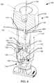
- FIGS. 4 and 5 are isometric views of the burner 100 with portions shown in cross-section and the pressure relief valve 106 respectively in closed and open modes.
- FIGS. 6 and 7 are side cross-sectional views of the burner of FIGS. 4 and 5 , respectively.
- FIGS. 8 and 9 are bottom plan views of the burner of FIGS. 4 and 5 , respectively.
- the valve body rotator 114 can take on many different forms while providing the desired translation of gas flow pressure against the valve body 108 in the direction of the axis 112 into a rotation of the valve body 108 about the axis 112.
- the valve body rotator 114 comprises at least one bushing support 120 attached to the conduit or housing 102.
- Each of the bushing supports 120 includes a bushing 121 through which a shaft 122, which is attached to the valve body 108, extends.
- the shaft 122 is generally coaxial to the axis 112.
- the shaft 122 rotates with the rotation of the valve body 108 and moves along the axis 112 with the valve body 108.
- the one or more bushing supports 120 include arms 124 or other structure that are attached to the conduit or housing 102.
- the arms 124 maintain the shaft 122 in coaxial alignment with the axis 112 as the valve body 108 rotates and moves along the axis 112.
- the valve body rotator 114 includes a rod 126 having an end 128 coupled to a distal end 130 of the shaft 122, and an end 132 coupled to one of the bushing supports 120 or the conduit 102.
- the ends 128 and 132 are each coupled to the respective distal end 130 of the shaft 122 and the conduit 102 or bushing support 120 through a ball joint 134.
- the end 128 and the corresponding ball joint 134 is attached to the distal end 130 of the shaft 122 through a bell crank 136.
- the rod 126 is placed at an angle 138 relative to the axis 112, as best shown in FIG. 7 .
- the angle 138 affects the amount the valve body 108 is rotated about the axis 112 in response to movement of the valve body 108 along the axis 112.
- the angle 138 increases as the valve body 108 is displaced from the valve seat 110 along the axis 112.
- the pressure relief valve 106 includes one or more mechanical stops 140 that limit rotation of the bushing support 120 and/or limit movement of the valve body 108 along the axis 112.
- the burner 100 formed in accordance with embodiments described herein receives a flow of combustible gas, such as waste gas, at an inlet 142, which pressurizes the conduit or housing 102.
- a flow of combustible gas such as waste gas
- the valve body 108 is displaced from the valve seat 110 along the axis 112 and a flow of gas 107 is discharged through an opening between the valve body 108 and the valve seat 110, as shown in FIGS. 2 , 5 and 7 .
- the valve body rotator 114 imparts a rotation to the valve body 108.
- the rotation of the valve body 108 per unit length of displacement of the valve body 108 from the valve seat 110 along the axis 112 decreases as the valve body 108 moves further from the valve seat 110. In some embodiments, this reduction in the angular rotation of the valve body 108 is caused by the variable angle 138 formed between the rod 126 and the axis 112, as discussed above.
- valve body 108 has a Coanda shape, or other suitable shape.
- the movement of the valve body 108 along the axis 112 provides a substantially constant pressure for the gas flow 107 while accommodating for a wide range of volumetric gas flow rates.
- the cracking pressure for the valve body 108 may be determined by the mass of valve body 108.
- the velocity of the exiting gas flow 107 through the opening between the valve body 108 and the valve seat 110 may be tuned based on the mass of the valve body 108 and the diameter of the outlet 104 of the conduit102.
- the mass of the valve body 108 may be customized by pouring concrete within a cavity formed by walls 144 ( FIG. 4 ) of the valve body 108.
- the moment of inertia of the valve body 108 about the axis 112 is maximized by radially displacing the material of the valve body away from the axis 112.
- the central portion of the valve body 108 near the axis 112 may be removed to increase the moment of inertia of the valve body 108, as shown in FIG. 4 .
- valve body rotator 114 described with reference to FIGS. 4-9 is merely one of many forms that the valve body rotator 114 can have.
- Additional exemplary embodiments of the valve body rotator 114 include a screw-like design, in which a component attached to the shaft 122 is forced to follow a guide surface that drives rotation of the valve body 108 about the axis 112 as the valve body 108 moves along the axis 112.
- This may take the form of a screw and thread arrangement between the shaft 122 and the conduit 102.
- the shaft 122 may comprise a lead screw, which is received within a threaded bore having a fixed location relative to the conduit 102. As the valve body 108 moves along the axis 112, the lead screw is forced to rotate due to the engagement with the threaded bore.
- Other arrangements are also possible to form the desired valve body rotator 114.
- the pressure relief valve 106 formed in accordance with one or more embodiments described herein may also be applied to applications other than burners. Accordingly, some embodiments of the invention are directed to one or more embodiments of the pressure relief valve 106 alone and in combination with gas flow conduit or a housing 102. Thus, some embodiments of the invention are directed to a pressure relief valve or gas flow regulator 106 comprising the valve body 108 and the valve body rotator 114 in accordance with one or more embodiments described herein.
- the pressure relief valve 106 may be installed in any suitable conduit or housing 102 to provide pressure relief when the pressure within the conduit or housing 102 exceeds a cracking pressure of the valve 106.
- a pressure relief valve 106 comprising a valve body 108 configured to engage a valve seat 110 and move along an axis 112 relative to the valve seat 110 in response to a pressure within a conduit or housing 102, to which the pressure relief valve 106 is mounted or installed.
- the valve body rotator 114 is configured to rotate the valve body 108 about the axis 112 in response to movement of the valve body 108 along the axis 112 relative to the valve seat 110.
- Embodiments described above with regard to the valve body 108 and the valve body rotator 114 may also be applied to this embodiment of the pressure relief valve 106.
- FIG. 10 is a flowchart illustrating a method of regulating a flow of a combustible gas through an outlet 110 of conduit 102 of a burner in accordance with embodiments of the invention.
- a valve body 108 is moved along an axis 112 relative to a valve seat 110 located at the outlet 104 in response to changes in pressure or the gas flow at the outlet.
- the valve body 108 is rotated about the axis 112 responsive to the movement of the valve body 108 along the axis 112 using a valve body rotator 114.
- the valve body 108 engages the valve seat 110 when the pressure at the outlet 104 is below a threshold pressure. In some embodiments, the valve body 108 is displaced along the axis 112 from the valve seat 110 when the pressure at the outlet 104 is above the threshold pressure.
- combustible gas 107 is discharged through the outlet 104 at a substantially constant velocity when the valve body 108 is displaced from the valve seat 110 and the pressure at the outlet is above the threshold pressure, as shown in FIG. 2 .
- the combustible gas 107 is discharged through an opening formed between the valve body 108 and the valve seat 110 at the outlet 104, and is ignited using a pilot burner 143.
- an amount of rotation of the valve body 108 per unit length of movement of the valve body 108 along the axis 112 relative to the valve seat 110 is based on a distance 119 the valve body 108 is displaced from the valve seat 110, using the valve body rotator 114.
- the burner 100 comprises a shaft 122 attached to the valve body 108, one or more bushing supports 120 each having a fixed position relative to the conduit or housing 102, and one or more bushings 121, through which the shaft 122 extends.
- each bushing 121 is supported by one of the bushing supports 120 and is configured to maintain the shaft 122 in general coaxial alignment with the axis 112.
- the valve body rotator 114 comprises a rod 126 having a first end 128 coupled to the shaft 122 and a second end 132 coupled to one of the bushing supports 120 or the conduit or housing 102.
- the rotating step 152 comprises driving rotation of the valve body 108 and the shaft 122 about the axis 112 using the rod 126 responsive to the moving step 150.
- the rod 126 is placed at an angle 138 ( FIG. 7 ) relative to the axis 112.
- the method comprises changing the angle 138 responsive to the moving step 150.
Landscapes
- Engineering & Computer Science (AREA)
- General Engineering & Computer Science (AREA)
- Mechanical Engineering (AREA)
- Environmental & Geological Engineering (AREA)
- Feeding And Controlling Fuel (AREA)
- Mechanically-Actuated Valves (AREA)
- Taps Or Cocks (AREA)
Description
- There are many occasions in which waste gasses are disposed of using a flare stack burner. Such burners having conventionally utilized a flare tip comprising a valve body, such as a Coanda body, that is either free floating or spring-loaded against an outlet or valve seat of a gas pipe. Pressurized waste gas lifts the valve body off the valve seat to form a variable opening through which the waste gas is discharged and ignited by a pilot burner to dispose of the waste gas.
- The exit velocity of the gas through the variable opening changes in response to the displacement of the valve body off the valve seat. This occurs due to the variable load applied to the valve body by the spring. As pressure increases, the valve body is displaced further from the valve seat.
- The exit velocity of the gas past the spring-loaded flare tip increases as the square of the pressure. This can place significant volumetric gas flow limitations on spring-loaded flare tips due to exit velocity limitations (e.g. 122m/s or 400ft/s) commanded by some environmental standards.
- Additionally, at low pressures, conventional flare tips are known to produce "chatter." Chatter occurs when the gas produces enough pressure to lift the valve body off the valve seat, but not enough pressure to maintain the displacement of the valve body from the valve seat. Instead, the valve body repeatedly lifts off the valve seat and then drops back onto the valve set in a rapid manner, causing undesirable chatter noise. Additionally, such chatter can potentially damage to the valve seat.
- Document
US4021189 discloses a combustible gas burner including a housing having a an outlet and a pressure relief valve according to the preamble of claim 1. - Some embodiments of the invention are directed to a combustible gas burner. In some embodiments, the combustible gas burner includes gas flow conduit or a housing having an outlet and a pressure relief valve. The pressure relief valve includes a valve seat at the outlet, a valve body and a valve body rotator. The valve body is configured to engage the valve seat and move along an axis relative to the valve seat in response to a pressure at the outlet to regulate the flow of combustible gas through the outlet. The valve body rotator is configured to rotate the valve body about the axis in response to movement of the valve body along the axis relative to the valve seat. The rotational movement of the valve body can reduce or eliminate chatter.
- In some embodiments, the burner comprises a shaft attached to the valve body, one or more bushing supports, each having a fixed position relative to the conduit, and one or more bushings, through which the shaft extends, each bushing supported by one of the bushing supports and configured to maintain the shaft in general alignment with the axis. In some embodiments, the valve body rotator comprises a rod having a first end coupled to the shaft and a second end coupled to one of the bushing supports. In some embodiments, rotation of the valve body and the shaft about the axis is driven using the rod responsive to movement of the valve body along the axis relative to the valve seat in response to pressure changes or gas flow changes at the outlet. In some embodiments, the rod is placed at an angle relative to the axis, and the angle is changed in response to moving the valve body along the axis relative to the valve seat in response to pressure or gas flow changes at the outlet.
- In some embodiments of the burner, the valve body engages the valve seat to place the pressure relief valve in a closed mode when the pressure at the outlet is below a threshold pressure. In some embodiments, pressure-driven movement of the valve body along the axis displaces the valve body from the valve seat to place the pressure relief valve in an open mode when the pressure at the outlet is above the threshold pressure. In some embodiments, the combustible gas is discharged through the outlet at a substantially constant velocity when the pressure relief valve is in the open mode. In some embodiments, the valve body rotator is within the conduit. In some embodiments, the valve body rotator is configured to accelerate the rotation of the valve body about the axis in response to fluctuations in the pressure at the outlet. In some embodiments, the valve body rotator is configured to vary an amount of rotation of the valve body per unit length of movement of the valve body along the axis relative to the valve seat based on a distance the valve body is displaced from the valve seat.
- In some embodiments, the valve body rotator is configured to vary an amount of rotation of the valve body per unit length of movement of the valve body along the axis relative to the valve seat based on a distance the valve body is displaced from the valve seat. In some embodiments, the valve body rotator is configured to decrease the amount of rotation of the valve body per unit length of movement of the valve body along the axis relative to the valve seat as the distance the valve body is displaced from the valve seat increases. In some embodiments, the valve body rotator is configured to increase the amount of rotation of the valve body per unit length of movement of the valve body along the axis relative to the valve seat as the distance the valve body is displaced from the valve seat decreases.
- Some embodiments of the burner comprise a shaft attached to the valve body, one or more bushing supports, and one or more bushings through which the shaft extends. In some embodiments, each bushing support has a fixed position relative to the conduit or housing. Each bushing is supported by one of the bushing supports and is configured to maintain the shaft in general coaxial alignment with the axis. In some embodiments, the burner comprises at least two bushing supports displaced from each other along the axis. In some embodiments, the bushing supports are each attached to the conduit or housing.
- In some embodiments, the valve body rotator comprises a rod having a first end coupled to the shaft and a second end coupled to one of the bushing supports. The rod drives rotation of the shaft and the valve body responsive to movement of the valve body along the axis relative to the valve seat. In some embodiments, the rod is displaced at an angle relative to the axis, and the angle changes in response to movement of the valve body along the axis relative to the valve seat.
- In some embodiments, the burner includes a pilot burner configured to ignite the combustible gas discharged through the outlet.
- Some embodiments of the invention are directed to a pressure relief valve or gas flow regulator comprising a valve body and a valve body rotator. The pressure relief valve may be installed in any suitable conduit or housing to provide pressure relief when the pressure within the conduit or housing exceeds a cracking pressure of the valve. In some embodiments, the valve body is configured to engage a valve seat and move along an axis relative to the valve seat in response to a pressure within the conduit or housing to which the pressure relief valve is mounted. In some embodiments, the valve body rotator is configured to rotate the valve body about the axis in response to movement of the valve body along the axis relative to the valve seat. Displacement of the valve body from the valve seat forms a variable opening through which gas or fluid within the conduit or housing is discharged. Embodiments of the pressure relief valve include those described herein with regard to the combustible gas burner embodiments.
- Additional embodiments are directed to a method of regulating a flow of combustible gas through an outlet of conduit or a housing of the burner. In some embodiments, a valve body is moved along an axis relative to a valve seat located at the outlet in response to changes in pressure or the gas flow at the outlet. The valve body is rotated about the axis responsive to the moving of the valve body along the axis relative to the valve seat using a valve body rotator.
- In some embodiments, the valve body engages the valve seat when the pressure at the outlet is below a threshold pressure, and the valve body is displaced along the axis from the valve seat when the pressure at the outlet is above the threshold pressure. In some embodiments, combustible gas is discharged through the outlet at a substantially constant velocity when the valve body is displaced from the valve seat and the pressure at the outlet is above the threshold pressure. In some embodiments, the combustible gas discharged through the outlet is ignited using a pilot burner. In some embodiments, an amount of rotation of the valve body per unit length of movement of the valve body along the axis relative to the valve seat is varied based on a distance the valve body is displaced from the valve seat using the valve body rotator.
- This Summary is provided to introduce a selection of concepts in a simplified form that are further described below in the Detailed Description. This Summary is not intended to identify key features or essential features of the claimed subject matter, nor is it intended to be used as an aid in determining the scope of the claimed subject matter. The claimed subject matter is not limited to implementations that solve any or all disadvantages noted in the Background.
-
-
FIGS. 1 and 2 are simplified block diagrams of a combustible gas burner respectively in closed and open modes, in accordance with embodiments of the invention. -
FIG. 3 is a simplified top view of a valve body rotator of a pressure relief valve of the combustible gas burners ofFIGS. 1 and 2 . -
FIGS. 4 and5 are isometric views of a combustible gas burner with portions shown in cross-section and a pressure relief valve respectively in closed and open modes. -
FIGS. 6 and 7 are side cross-sectional views of the burner ofFIGS. 4 and5 , respectively. -
FIGS. 8 and 9 are bottom plan views of the burner ofFIGS. 4 and5 , respectively. -
FIG. 10 is a flowchart illustrating a method of regulating a flow of combustible gas through an outlet of conduit of a burner in accordance with embodiments of the invention. - Embodiments of the invention are described more fully hereinafter with reference to the accompanying drawings. Elements that are identified using the same or similar reference characters refer to the same or similar elements. The various embodiments of the invention may, however, be embodied in many different forms and should not be construed as limited to the embodiments set forth herein. Rather, these embodiments are provided so that this disclosure will be thorough and complete, and will fully convey the scope of the invention to those skilled in the art.
- Specific details are given in the following description to provide a thorough understanding of the embodiments. However, it is understood by those of ordinary skill in the art that the embodiments may be practiced without these specific details. For example, circuits, systems, networks, processes, frames, supports, connectors, motors, processors, and other components may not be shown, or shown in block diagram form in order to not obscure the embodiments in unnecessary detail.
- The terminology used herein is for the purpose of describing particular embodiments only and is not intended to be limiting of the invention. As used herein, the singular forms "a", "an" and "the" are intended to include the plural forms as well, unless the context clearly indicates otherwise. It will be further understood that the terms "comprises" and/or "comprising," when used in this specification, specify the presence of stated features, integers, steps, operations, elements, and/or components, but do not preclude the presence or addition of one or more other features, integers, steps, operations, elements, components, and/or groups thereof.
- It will be understood that when an element is referred to as being "connected" or "coupled" to another element, it can be directly connected or coupled to the other element or intervening elements may be present. In contrast, if an element is referred to as being "directly connected" or "directly coupled" to another element, there are no intervening elements present.
- It will be understood that, although the terms first, second, etc. may be used herein to describe various elements, these elements should not be limited by these terms. These terms are only used to distinguish one element from another. Thus, a first element could be termed a second element without departing from the teachings of the present invention.
- Unless otherwise defined, all terms (including technical and scientific terms) used herein have the same meaning as commonly understood by one of ordinary skill in the art to which this invention belongs. It will be further understood that terms, such as those defined in commonly used dictionaries, should be interpreted as having a meaning that is consistent with their meaning in the context of the relevant art and will not be interpreted in an idealized or overly formal sense unless expressly so defined herein.
- Embodiments of the invention may also be described using flowchart illustrations and block diagrams. Although a flowchart may describe the operations as a sequential process, many of the operations can be performed in parallel or concurrently. In addition, the order of the operations may be rearranged. A process is terminated when its operations are completed, but could have additional steps not included in a figure or described herein.
- It is understood that one or more of the blocks (of the flowcharts and block diagrams) may be implemented by computer program instructions. These program instructions may be provided to a processor circuit, such as a microprocessor, microcontroller or other processor, which executes the instructions to implement the functions specified in the block or blocks through a series of operational steps to be performed by the processor(s) and corresponding hardware components.
-
FIGS. 1-3 illustrate embodiments of acombustible burner 100, such as a flare stack burner, formed in accordance with one or more embodiments of the invention.FIGS. 1 and 2 are simplified block diagrams of acombustible gas burner 100 respectively in closed and open modes, in accordance with embodiments of the invention.FIG. 3 is a simplified top view of a valve body rotator of a pressure relief valve of the combustible gas burners ofFIGS. 1 and 2 . - In some embodiments, the
burner 100 includes gas flow conduit or ahousing 102 including anoutlet 104, and a pressure relief valve or gas flow regulator (hereinafter "pressure relief valve") 106. Thepressure relief valve 106 is generally configured to possibly seal and provide a variable opening at theoutlet 104 of thegas flow conduit 102 to regulate the flow of combustible gas, which is represented by arrows 107 (FIG. 2 ), through theoutlet 104. - In some embodiments, the
pressure relief valve 106 includes avalve body 108 that engages avalve seat 110 at theoutlet 104 when in a closed mode, as shown inFIG. 1 to form a seal at thevalve seat 110 to prevent or at least restrict the flow of gas through theoutlet 104. In a flare stack burner, thevalve body 108 may be referred to as a "flare tip." Thevalve body 108 is configured to move along anaxis 112 relative to thegas flow conduit 102 and thevalve seat 110 in response to pressurized gas within the conduit102, or at theoutlet 104 to place thepressure relief valve 106 in an open mode, in which thevalve body 108 is displaced from thevalve seat 110, as illustrated inFIG. 2 . This forms an opening, such an annular opening, between thevalve body 108 and thevalve seat 110 that varies in response to the pressure at theoutlet 104. - In some embodiments, the
pressure relief valve 106 comprises avalve body rotator 114 that translates the pressure-driven movement of thevalve body 108 along theaxis 112 into a rotation of thevalve body 108, or other mass coupled to thevalve body 108, about theaxis 112, as indicated byarrow 116 inFIGS. 2 and 3 . In other words, when the pressurized gas flow within theconduit 102 exceeds a threshold pressure (i.e., cracking pressure) on thevalve body 108, thevalve body 108 rotates about theaxis 112 as it moves along theaxis 112 away from thevalve seat 110. - The mass of the
valve body 108 controls the cracking pressure required to transition thevalve body 108 from the closed mode (FIG. 1 ) to the open mode (FIG. 2 ). The rotational inertia of thevalve body 108 operates as a damper that dampens the movement of thevalve body 108 along theaxis 112 responsive to changes in the pressure of the gas flow. This rotational dampening prevents thevalve body 108 from rapidly moving along theaxis 112 in response to pressure changes in the gas flow when thevalve body 108 is engaging or is in close proximity to thevalve seat 110. This rotational dampening of thevalve body 108 eliminates or reduces the chatter that would otherwise occur if a conventional spring-loaded flare tip were used. - For instance, when the pressure of the gas within the
conduit 102 reaches the cracking pressure required to displace thevalve body 108 off thevalve seat 110, thevalve body rotator 114 causes thevalve body 108, or other attached mass, to rotate about theaxis 112 as thevalve body 108 rises off thevalve seat 110 and thegas flow 107 is discharged through an opening between thevalve body 108 and thevalve seat 110 at theoutlet 104. Fluctuations in the pressure of the gas flow produce an acceleration to the rotation of thevalve body 108 as thevalve body 108 moves further from thevalve seat 110 during a pressure increase, or toward thevalve seat 110 during a pressure decrease. This rotation of thevalve body 108 along with the relatively high rotational inertia of thevalve body 108 relative to the foreseen gas flow pressures, prevents thevalve body 108 from producing the undesired chatter against thevalve seat 110 at gas flow pressures around the cracking pressure of thepressure relief valve 106. - In one exemplary embodiment, the
valve body 108 is angularly displaced about theaxis 112 at an angle 118 (FIG. 3 ) of approximately 5 degrees as thevalve body 108 lifts off the valve seat 110 a distance 119 (FIG. 2 ) of approximately 0.030 inches. In some embodiments, the amount ofrotation 118 of the valve body per unit length of movement along theaxis 112 varies based on thedistance 119 thevalve body 108 is displaced from thevalve seat 110. In some embodiments, the amount of rotation of thevalve body 108 about theaxis 112 per unit length of movement along theaxis 112 is greater when thevalve body 108 is in close proximity to thevalve seat 110, than when thevalve body 108 is displaced from thevalve seat 110. This allows for a greater translation of the pressure on thevalve body 108 to rotation of thevalve body 108 about theaxis 112 when thevalve body 108 is in close proximity to thevalve seat 110 in order to have the maximum effect on the reduction of chatter between thevalve body 108 and thevalve seat 110. As thevalve body 108 moves away from thevalve seat 110 along theaxis 112, the amount of rotation of thevalve body 108 in response to the movement along theaxis 112 is reduced and thevalve body 108 operates more like a free floating valve body, in some embodiments. - Additional exemplary embodiments of the
pressure relief valve 106 will be described with reference toFIGS. 4-9 .FIGS. 4 and5 are isometric views of theburner 100 with portions shown in cross-section and thepressure relief valve 106 respectively in closed and open modes.FIGS. 6 and 7 are side cross-sectional views of the burner ofFIGS. 4 and5 , respectively.FIGS. 8 and 9 are bottom plan views of the burner ofFIGS. 4 and5 , respectively. - The
valve body rotator 114 can take on many different forms while providing the desired translation of gas flow pressure against thevalve body 108 in the direction of theaxis 112 into a rotation of thevalve body 108 about theaxis 112. In some embodiments, thevalve body rotator 114 comprises at least onebushing support 120 attached to the conduit orhousing 102. Each of the bushing supports 120 includes abushing 121 through which ashaft 122, which is attached to thevalve body 108, extends. In some embodiments, theshaft 122 is generally coaxial to theaxis 112. In some embodiments, theshaft 122 rotates with the rotation of thevalve body 108 and moves along theaxis 112 with thevalve body 108. In some embodiments, the one or more bushing supports 120 includearms 124 or other structure that are attached to the conduit orhousing 102. Thearms 124 maintain theshaft 122 in coaxial alignment with theaxis 112 as thevalve body 108 rotates and moves along theaxis 112. - In some exemplary embodiments, the
valve body rotator 114 includes arod 126 having anend 128 coupled to adistal end 130 of theshaft 122, and anend 132 coupled to one of the bushing supports 120 or theconduit 102. In some embodiments, theends distal end 130 of theshaft 122 and theconduit 102 orbushing support 120 through a ball joint 134. In some embodiments, theend 128 and the corresponding ball joint 134 is attached to thedistal end 130 of theshaft 122 through abell crank 136. - In some embodiments, the
rod 126 is placed at anangle 138 relative to theaxis 112, as best shown inFIG. 7 . Theangle 138 affects the amount thevalve body 108 is rotated about theaxis 112 in response to movement of thevalve body 108 along theaxis 112. In some embodiments, theangle 138 increases as thevalve body 108 is displaced from thevalve seat 110 along theaxis 112. In some embodiments, thepressure relief valve 106 includes one or moremechanical stops 140 that limit rotation of thebushing support 120 and/or limit movement of thevalve body 108 along theaxis 112. - As the
end 132 of therod 126 is fixed relative to the conduit102, movement of thevalve body 108 along theaxis 112 relative to theconduit 102 causes an increase in theangle 138 and rotation of the bell crank 136 about theaxis 112 to which theend 132 of therod 126 is attached, as shown inFIGS. 6 and 7 . This in turn drives the rotation of theshaft 122 and thevalve body 108 about theaxis 112. Theangle 138 continues to increase as thevalve body 108 is displaced further from thevalve seat 110, thereby reducing the amount of rotation imparted to thevalve body 108 per unit of movement along theaxis 112. - In operation, the
burner 100 formed in accordance with embodiments described herein receives a flow of combustible gas, such as waste gas, at aninlet 142, which pressurizes the conduit orhousing 102. When the pressure within theconduit 102 exceeds the cracking pressure, thevalve body 108 is displaced from thevalve seat 110 along theaxis 112 and a flow ofgas 107 is discharged through an opening between thevalve body 108 and thevalve seat 110, as shown inFIGS. 2 ,5 and7 . During this pressure-driven displacement of thevalve body 108 from thevalve seat 110, thevalve body rotator 114 imparts a rotation to thevalve body 108. As mentioned above, in some embodiments, the rotation of thevalve body 108 per unit length of displacement of thevalve body 108 from thevalve seat 110 along theaxis 112 decreases as thevalve body 108 moves further from thevalve seat 110. In some embodiments, this reduction in the angular rotation of thevalve body 108 is caused by thevariable angle 138 formed between therod 126 and theaxis 112, as discussed above. - The variable opening formed between the
valve body 108 and thevalve seat 110 allows for the gas flow to pass over thevalve body 108 and be ignited by a suitable pilot burner 143 (FIGS. 1 and 2 ), in accordance with conventional burners. In some embodiments, thevalve body 108 has a Coanda shape, or other suitable shape. - The movement of the
valve body 108 along theaxis 112 provides a substantially constant pressure for thegas flow 107 while accommodating for a wide range of volumetric gas flow rates. The cracking pressure for thevalve body 108 may be determined by the mass ofvalve body 108. As a result, the velocity of the exitinggas flow 107 through the opening between thevalve body 108 and thevalve seat 110 may be tuned based on the mass of thevalve body 108 and the diameter of theoutlet 104 of the conduit102. In some embodiments, the mass of thevalve body 108 may be customized by pouring concrete within a cavity formed by walls 144 (FIG. 4 ) of thevalve body 108. - In some embodiments, the moment of inertia of the
valve body 108 about theaxis 112 is maximized by radially displacing the material of the valve body away from theaxis 112. The central portion of thevalve body 108 near theaxis 112 may be removed to increase the moment of inertia of thevalve body 108, as shown inFIG. 4 . - It is understood that the exemplary
valve body rotator 114 described with reference toFIGS. 4-9 is merely one of many forms that thevalve body rotator 114 can have. Additional exemplary embodiments of thevalve body rotator 114 include a screw-like design, in which a component attached to theshaft 122 is forced to follow a guide surface that drives rotation of thevalve body 108 about theaxis 112 as thevalve body 108 moves along theaxis 112. This may take the form of a screw and thread arrangement between theshaft 122 and theconduit 102. For instance, theshaft 122 may comprise a lead screw, which is received within a threaded bore having a fixed location relative to theconduit 102. As thevalve body 108 moves along theaxis 112, the lead screw is forced to rotate due to the engagement with the threaded bore. Other arrangements are also possible to form the desiredvalve body rotator 114. - It is understood by those skilled in the art that the
pressure relief valve 106 formed in accordance with one or more embodiments described herein may also be applied to applications other than burners. Accordingly, some embodiments of the invention are directed to one or more embodiments of thepressure relief valve 106 alone and in combination with gas flow conduit or ahousing 102. Thus, some embodiments of the invention are directed to a pressure relief valve orgas flow regulator 106 comprising thevalve body 108 and thevalve body rotator 114 in accordance with one or more embodiments described herein. Thepressure relief valve 106 may be installed in any suitable conduit orhousing 102 to provide pressure relief when the pressure within the conduit orhousing 102 exceeds a cracking pressure of thevalve 106. - Thus, some embodiments of the invention are directed to a
pressure relief valve 106 comprising avalve body 108 configured to engage avalve seat 110 and move along anaxis 112 relative to thevalve seat 110 in response to a pressure within a conduit orhousing 102, to which thepressure relief valve 106 is mounted or installed. Thevalve body rotator 114 is configured to rotate thevalve body 108 about theaxis 112 in response to movement of thevalve body 108 along theaxis 112 relative to thevalve seat 110. Embodiments described above with regard to thevalve body 108 and thevalve body rotator 114 may also be applied to this embodiment of thepressure relief valve 106. - Some embodiments of the invention are directed to a method of regulating a flow of gas through
conduit 102 using thepressure relief valve 106 in accordance with one or more embodiments described herein.FIG. 10 is a flowchart illustrating a method of regulating a flow of a combustible gas through anoutlet 110 ofconduit 102 of a burner in accordance with embodiments of the invention. - At 150 of the method, a
valve body 108 is moved along anaxis 112 relative to avalve seat 110 located at theoutlet 104 in response to changes in pressure or the gas flow at the outlet. At 152, thevalve body 108 is rotated about theaxis 112 responsive to the movement of thevalve body 108 along theaxis 112 using avalve body rotator 114. - In some embodiments of the method, the
valve body 108 engages thevalve seat 110 when the pressure at theoutlet 104 is below a threshold pressure. In some embodiments, thevalve body 108 is displaced along theaxis 112 from thevalve seat 110 when the pressure at theoutlet 104 is above the threshold pressure. - In some embodiments of the method,
combustible gas 107 is discharged through theoutlet 104 at a substantially constant velocity when thevalve body 108 is displaced from thevalve seat 110 and the pressure at the outlet is above the threshold pressure, as shown inFIG. 2 . In some embodiments of the method, thecombustible gas 107 is discharged through an opening formed between thevalve body 108 and thevalve seat 110 at theoutlet 104, and is ignited using apilot burner 143. - In some embodiments of the method, an amount of rotation of the
valve body 108 per unit length of movement of thevalve body 108 along theaxis 112 relative to thevalve seat 110 is based on adistance 119 thevalve body 108 is displaced from thevalve seat 110, using thevalve body rotator 114. - In some embodiments of the method, the
burner 100 comprises ashaft 122 attached to thevalve body 108, one or more bushing supports 120 each having a fixed position relative to the conduit orhousing 102, and one ormore bushings 121, through which theshaft 122 extends. In some embodiments, eachbushing 121 is supported by one of the bushing supports 120 and is configured to maintain theshaft 122 in general coaxial alignment with theaxis 112. - In some embodiments, the
valve body rotator 114 comprises arod 126 having afirst end 128 coupled to theshaft 122 and asecond end 132 coupled to one of the bushing supports 120 or the conduit orhousing 102. In some embodiments, therotating step 152 comprises driving rotation of thevalve body 108 and theshaft 122 about theaxis 112 using therod 126 responsive to the movingstep 150. In some embodiments, therod 126 is placed at an angle 138 (FIG. 7 ) relative to theaxis 112. In some embodiments, the method comprises changing theangle 138 responsive to the movingstep 150. - Although the present invention has been described with reference to preferred embodiments, workers skilled in the art will recognize that changes may be made in form and detail without departing from the spirit and scope of the invention.
Claims (15)
- A combustible gas burner (100) comprising:gas flow conduit (102) including an outlet (104); anda pressure relief valve (106) comprising:a valve seat (110) at the outlet;a valve body (108) configured to engage the valve seat and move along an axis (112) relative to the valve seat in response to a pressure at the outlet to regulate a flow of combustible gas through the outlet; characterized in that:
a valve body rotator (114) configured to rotate the valve body about the axis in response to movement of the valve body along the axis relative to the valve seat. - The burner according to claim 1, wherein:the valve body (108) engages the valve seat to place the pressure relief valve (106) in a closed mode
when the pressure at the outlet is below a threshold pressure; andpressure-driven movement of the valve body along the axis displaces the valve body from the valve seat (110) to place the pressure relief valve in an open mode when the pressure
at the outlet is above the threshold pressure. - The burner according to claim 2, wherein combustible gas is discharged through the outlet at a substantially constant velocity when the pressure relief valve (106) is in the open mode.
- The burner according to any of claims 1-3, wherein the valve body rotator (114) is within the conduit.
- The burner according to any of claims 1-4, wherein the valve body rotator (114) is configured to accelerate the rotation of the valve body about the axis in response to fluctuations in the pressure at the outlet.
- The burner according to any of claims 1-5, wherein the valve body rotator (114) is configured to vary an amount of rotation of the valve body (108) per unit length of movement of the valve body along the axis relative to the valve seat based on a distance the valve body is displaced from the valve seat (110).
- The burner according to claim 6, wherein:the valve body rotator is configured to decrease the amount of rotation of the valve body (108) per unit length of movement of the valve body along the axis relative to the valve seat as the distance the valve body is displaced from the valve seat increases; andthe valve body rotator is configured to increase the amount of rotation of the valve body per unit length of movement of the valve body along the axis relative to the valve seat (110) as the distance the valve body is displaced from the valve seat decreases.
- The burner according to any of claims 1-7, wherein the burner comprises:a shaft attached to the valve body;one or more bushing supports, (120) each having a fixed position relative to the conduit; andone or more bushings, through which the shaft extends, each bushing supported by one of the bushing supports and configured to maintain the shaft in general alignment with the axis (112).
- The burner according to any of claims 1-8, further comprising a pilot burner configured to ignite the combustible gas discharged through the outlet. (104).
- A method of regulating a flow of combustible gas through an outlet of conduit or a housing of a burner comprising steps of:moving (150) a valve body (108) along an axis relative to a valve seat located at the outlet in response to changes in pressure at the outlet; androtating (152) the valve body about the axis responsive to the moving step using a valve body rotator.
- The method according to claim 10, further comprising:engaging the valve seat with the valve body when the pressure at the outlet is below a threshold pressure; anddisplacing the valve body along the axis from the valve seat when the pressure at the outlet (104) is above the threshold pressure.
- The method according to claim 11, further comprising discharging the combustible gas through the outlet at a substantially constant velocity when the valve body is displaced from the valve seat and the pressure at the outlet (104) is above the threshold pressure, and igniting the combustible gas discharged through the outlet using a pilot burner.
- The method according to any of claims 10-12, further comprising varying an amount of rotation of the valve body per unit length of movement of the valve body along the axis (112) relative to the valve seat based on a distance the valve body is displaced from the valve seat using the valve body rotator.
- The method according to any of claims 10-13, wherein:the burner comprises:a shaft attached to the valve body;one or more bushing supports, each having a fixed position relative to the conduit; andone or more bushings, through which the shaft extends, each bushing supported by one of the bushing supports (120) and configured to maintain the shaft in general alignment with the axis;the valve body rotator comprises a rod having a first end coupled to the shaft and a second end coupled to one of the bushing supports; andthe rotating step comprises driving rotation of the valve body and the shaft about the axis using the rod responsive to the moving step.
- The method according to claim 14, wherein:the rod is placed at an angle relative to the axis; (112) andthe method comprises changing the angle responsive to the moving step.
Priority Applications (1)
| Application Number | Priority Date | Filing Date | Title |
|---|---|---|---|
| PL14702709T PL2946143T3 (en) | 2013-01-18 | 2014-01-16 | Pressure relief valve with rotating damper |
Applications Claiming Priority (2)
| Application Number | Priority Date | Filing Date | Title |
|---|---|---|---|
| US201361754219P | 2013-01-18 | 2013-01-18 | |
| PCT/US2014/011780 WO2014113529A1 (en) | 2013-01-18 | 2014-01-16 | Pressure relief valve with rotating damper |
Publications (2)
| Publication Number | Publication Date |
|---|---|
| EP2946143A1 EP2946143A1 (en) | 2015-11-25 |
| EP2946143B1 true EP2946143B1 (en) | 2018-08-29 |
Family
ID=50033827
Family Applications (1)
| Application Number | Title | Priority Date | Filing Date |
|---|---|---|---|
| EP14702709.8A Not-in-force EP2946143B1 (en) | 2013-01-18 | 2014-01-16 | Pressure relief valve with rotating damper |
Country Status (6)
| Country | Link |
|---|---|
| US (1) | US9970657B2 (en) |
| EP (1) | EP2946143B1 (en) |
| CN (1) | CN105026837B (en) |
| CA (1) | CA2896626C (en) |
| PL (1) | PL2946143T3 (en) |
| WO (1) | WO2014113529A1 (en) |
Families Citing this family (4)
| Publication number | Priority date | Publication date | Assignee | Title |
|---|---|---|---|---|
| US9970658B2 (en) | 2013-01-18 | 2018-05-15 | Steffes Corporation | Pressure relief valve with rotating damper |
| EP2946143B1 (en) | 2013-01-18 | 2018-08-29 | Steffes Corporation | Pressure relief valve with rotating damper |
| US9791067B2 (en) | 2014-07-31 | 2017-10-17 | Steffes Corporation | Flare tip valve dampening |
| US12372235B1 (en) | 2021-02-04 | 2025-07-29 | David Bacon | Flare gas system |
Family Cites Families (9)
| Publication number | Priority date | Publication date | Assignee | Title |
|---|---|---|---|---|
| US3547567A (en) * | 1968-07-25 | 1970-12-15 | Smoke Ban Mfg Inc | Flare stack combustion tip |
| US3711236A (en) * | 1971-08-02 | 1973-01-16 | Emerson Electric Co | Gas burner control device with low pressure cutoff |
| US4021189A (en) | 1975-01-16 | 1977-05-03 | Porta-Test Manufacturing Ltd. | Gas burner |
| US4099908A (en) * | 1976-08-13 | 1978-07-11 | Martin Josef Beckmann | Low pressure gas burner |
| EP0026067B1 (en) * | 1979-09-24 | 1984-06-13 | John Zink Company | Large capacity air-powered smokeless flare |
| CN2318516Y (en) * | 1997-10-24 | 1999-05-12 | 李水明 | Multifunction pressure-reducing valve |
| US8985094B2 (en) | 2011-04-08 | 2015-03-24 | David Deng | Heating system |
| US9970658B2 (en) | 2013-01-18 | 2018-05-15 | Steffes Corporation | Pressure relief valve with rotating damper |
| EP2946143B1 (en) | 2013-01-18 | 2018-08-29 | Steffes Corporation | Pressure relief valve with rotating damper |
-
2014
- 2014-01-16 EP EP14702709.8A patent/EP2946143B1/en not_active Not-in-force
- 2014-01-16 PL PL14702709T patent/PL2946143T3/en unknown
- 2014-01-16 CA CA2896626A patent/CA2896626C/en active Active
- 2014-01-16 US US14/409,762 patent/US9970657B2/en active Active
- 2014-01-16 WO PCT/US2014/011780 patent/WO2014113529A1/en not_active Ceased
- 2014-01-16 CN CN201480005227.3A patent/CN105026837B/en not_active Expired - Fee Related
Also Published As
| Publication number | Publication date |
|---|---|
| EP2946143A1 (en) | 2015-11-25 |
| CN105026837B (en) | 2017-03-15 |
| PL2946143T3 (en) | 2018-12-31 |
| WO2014113529A1 (en) | 2014-07-24 |
| CN105026837A (en) | 2015-11-04 |
| CA2896626A1 (en) | 2014-07-24 |
| US20150153042A1 (en) | 2015-06-04 |
| US9970657B2 (en) | 2018-05-15 |
| CA2896626C (en) | 2019-04-02 |
Similar Documents
| Publication | Publication Date | Title |
|---|---|---|
| CA2896626C (en) | Pressure relief valve with rotating damper | |
| EP2373910B1 (en) | Fluid control valve | |
| CN104975994B (en) | Fuel vapour control device | |
| US9791067B2 (en) | Flare tip valve dampening | |
| EP3056689B1 (en) | Governing valve device and power generating equipment | |
| CN106321285B (en) | The fixed solid rocket ramjet gas flow regulating device of cone valve | |
| WO2016074555A1 (en) | Electronic expansion valve | |
| CN103122882A (en) | Adjustable pilot overflow valve | |
| CN106438108A (en) | Large-regulation-ratio type fuel gas flow regulation device for solid rocket ramjet | |
| US9970658B2 (en) | Pressure relief valve with rotating damper | |
| EP2868970B1 (en) | Regulating device | |
| CN108361393A (en) | Electric expansion valve | |
| EP2818774B1 (en) | Regulating valve | |
| CN102829222A (en) | Pressure-difference-variable flow control valve | |
| CN102454652B (en) | Adjustable hydraulic pilot opening mechanism | |
| CN111954776A (en) | Electric valve | |
| CN103122883B (en) | Adjustable pilot reduction valve | |
| AU2015202585B2 (en) | Pressure relief valve with rotating damper | |
| JP7621693B2 (en) | Motor-operated valve | |
| CN111120662A (en) | Pneumatic buffering angle seat valve | |
| RU2514817C1 (en) | Noise killer | |
| KR101162886B1 (en) | Pressure-compensated flow control valve | |
| CN201233538Y (en) | Stepped liquid saving flow regulating apparatus | |
| CN106090359B (en) | A kind of natural gas line pressure adjusting part | |
| CN109209682A (en) | A kind of motor-driven Pasty Propellant Rocket Engine fireproof tempering device |
Legal Events
| Date | Code | Title | Description |
|---|---|---|---|
| PUAI | Public reference made under article 153(3) epc to a published international application that has entered the european phase |
Free format text: ORIGINAL CODE: 0009012 |
|
| 17P | Request for examination filed |
Effective date: 20150814 |
|
| AK | Designated contracting states |
Kind code of ref document: A1 Designated state(s): AL AT BE BG CH CY CZ DE DK EE ES FI FR GB GR HR HU IE IS IT LI LT LU LV MC MK MT NL NO PL PT RO RS SE SI SK SM TR |
|
| AX | Request for extension of the european patent |
Extension state: BA ME |
|
| DAX | Request for extension of the european patent (deleted) | ||
| RIN1 | Information on inventor provided before grant (corrected) |
Inventor name: MAYER, TODD, C. Inventor name: KUDRNA, KENT, J. Inventor name: KOVASH, DEAN, A. |
|
| GRAP | Despatch of communication of intention to grant a patent |
Free format text: ORIGINAL CODE: EPIDOSNIGR1 |
|
| STAA | Information on the status of an ep patent application or granted ep patent |
Free format text: STATUS: GRANT OF PATENT IS INTENDED |
|
| INTG | Intention to grant announced |
Effective date: 20180320 |
|
| GRAS | Grant fee paid |
Free format text: ORIGINAL CODE: EPIDOSNIGR3 |
|
| GRAA | (expected) grant |
Free format text: ORIGINAL CODE: 0009210 |
|
| STAA | Information on the status of an ep patent application or granted ep patent |
Free format text: STATUS: THE PATENT HAS BEEN GRANTED |
|
| AK | Designated contracting states |
Kind code of ref document: B1 Designated state(s): AL AT BE BG CH CY CZ DE DK EE ES FI FR GB GR HR HU IE IS IT LI LT LU LV MC MK MT NL NO PL PT RO RS SE SI SK SM TR |
|
| REG | Reference to a national code |
Ref country code: GB Ref legal event code: FG4D |
|
| REG | Reference to a national code |
Ref country code: CH Ref legal event code: EP |
|
| REG | Reference to a national code |
Ref country code: AT Ref legal event code: REF Ref document number: 1035561 Country of ref document: AT Kind code of ref document: T Effective date: 20180915 |
|
| REG | Reference to a national code |
Ref country code: IE Ref legal event code: FG4D |
|
| REG | Reference to a national code |
Ref country code: DE Ref legal event code: R096 Ref document number: 602014031259 Country of ref document: DE |
|
| REG | Reference to a national code |
Ref country code: NL Ref legal event code: MP Effective date: 20180829 |
|
| REG | Reference to a national code |
Ref country code: LT Ref legal event code: MG4D |
|
| PG25 | Lapsed in a contracting state [announced via postgrant information from national office to epo] |
Ref country code: RS Free format text: LAPSE BECAUSE OF FAILURE TO SUBMIT A TRANSLATION OF THE DESCRIPTION OR TO PAY THE FEE WITHIN THE PRESCRIBED TIME-LIMIT Effective date: 20180829 Ref country code: IS Free format text: LAPSE BECAUSE OF FAILURE TO SUBMIT A TRANSLATION OF THE DESCRIPTION OR TO PAY THE FEE WITHIN THE PRESCRIBED TIME-LIMIT Effective date: 20181229 Ref country code: LT Free format text: LAPSE BECAUSE OF FAILURE TO SUBMIT A TRANSLATION OF THE DESCRIPTION OR TO PAY THE FEE WITHIN THE PRESCRIBED TIME-LIMIT Effective date: 20180829 Ref country code: NO Free format text: LAPSE BECAUSE OF FAILURE TO SUBMIT A TRANSLATION OF THE DESCRIPTION OR TO PAY THE FEE WITHIN THE PRESCRIBED TIME-LIMIT Effective date: 20181129 Ref country code: GR Free format text: LAPSE BECAUSE OF FAILURE TO SUBMIT A TRANSLATION OF THE DESCRIPTION OR TO PAY THE FEE WITHIN THE PRESCRIBED TIME-LIMIT Effective date: 20181130 Ref country code: NL Free format text: LAPSE BECAUSE OF FAILURE TO SUBMIT A TRANSLATION OF THE DESCRIPTION OR TO PAY THE FEE WITHIN THE PRESCRIBED TIME-LIMIT Effective date: 20180829 Ref country code: BG Free format text: LAPSE BECAUSE OF FAILURE TO SUBMIT A TRANSLATION OF THE DESCRIPTION OR TO PAY THE FEE WITHIN THE PRESCRIBED TIME-LIMIT Effective date: 20181129 Ref country code: FI Free format text: LAPSE BECAUSE OF FAILURE TO SUBMIT A TRANSLATION OF THE DESCRIPTION OR TO PAY THE FEE WITHIN THE PRESCRIBED TIME-LIMIT Effective date: 20180829 Ref country code: SE Free format text: LAPSE BECAUSE OF FAILURE TO SUBMIT A TRANSLATION OF THE DESCRIPTION OR TO PAY THE FEE WITHIN THE PRESCRIBED TIME-LIMIT Effective date: 20180829 |
|
| REG | Reference to a national code |
Ref country code: AT Ref legal event code: MK05 Ref document number: 1035561 Country of ref document: AT Kind code of ref document: T Effective date: 20180829 |
|
| PG25 | Lapsed in a contracting state [announced via postgrant information from national office to epo] |
Ref country code: LV Free format text: LAPSE BECAUSE OF FAILURE TO SUBMIT A TRANSLATION OF THE DESCRIPTION OR TO PAY THE FEE WITHIN THE PRESCRIBED TIME-LIMIT Effective date: 20180829 Ref country code: AL Free format text: LAPSE BECAUSE OF FAILURE TO SUBMIT A TRANSLATION OF THE DESCRIPTION OR TO PAY THE FEE WITHIN THE PRESCRIBED TIME-LIMIT Effective date: 20180829 Ref country code: HR Free format text: LAPSE BECAUSE OF FAILURE TO SUBMIT A TRANSLATION OF THE DESCRIPTION OR TO PAY THE FEE WITHIN THE PRESCRIBED TIME-LIMIT Effective date: 20180829 |
|
| PG25 | Lapsed in a contracting state [announced via postgrant information from national office to epo] |
Ref country code: RO Free format text: LAPSE BECAUSE OF FAILURE TO SUBMIT A TRANSLATION OF THE DESCRIPTION OR TO PAY THE FEE WITHIN THE PRESCRIBED TIME-LIMIT Effective date: 20180829 Ref country code: AT Free format text: LAPSE BECAUSE OF FAILURE TO SUBMIT A TRANSLATION OF THE DESCRIPTION OR TO PAY THE FEE WITHIN THE PRESCRIBED TIME-LIMIT Effective date: 20180829 Ref country code: EE Free format text: LAPSE BECAUSE OF FAILURE TO SUBMIT A TRANSLATION OF THE DESCRIPTION OR TO PAY THE FEE WITHIN THE PRESCRIBED TIME-LIMIT Effective date: 20180829 Ref country code: ES Free format text: LAPSE BECAUSE OF FAILURE TO SUBMIT A TRANSLATION OF THE DESCRIPTION OR TO PAY THE FEE WITHIN THE PRESCRIBED TIME-LIMIT Effective date: 20180829 Ref country code: CZ Free format text: LAPSE BECAUSE OF FAILURE TO SUBMIT A TRANSLATION OF THE DESCRIPTION OR TO PAY THE FEE WITHIN THE PRESCRIBED TIME-LIMIT Effective date: 20180829 |
|
| PG25 | Lapsed in a contracting state [announced via postgrant information from national office to epo] |
Ref country code: SM Free format text: LAPSE BECAUSE OF FAILURE TO SUBMIT A TRANSLATION OF THE DESCRIPTION OR TO PAY THE FEE WITHIN THE PRESCRIBED TIME-LIMIT Effective date: 20180829 Ref country code: DK Free format text: LAPSE BECAUSE OF FAILURE TO SUBMIT A TRANSLATION OF THE DESCRIPTION OR TO PAY THE FEE WITHIN THE PRESCRIBED TIME-LIMIT Effective date: 20180829 Ref country code: SK Free format text: LAPSE BECAUSE OF FAILURE TO SUBMIT A TRANSLATION OF THE DESCRIPTION OR TO PAY THE FEE WITHIN THE PRESCRIBED TIME-LIMIT Effective date: 20180829 |
|
| REG | Reference to a national code |
Ref country code: DE Ref legal event code: R097 Ref document number: 602014031259 Country of ref document: DE |
|
| PLBE | No opposition filed within time limit |
Free format text: ORIGINAL CODE: 0009261 |
|
| STAA | Information on the status of an ep patent application or granted ep patent |
Free format text: STATUS: NO OPPOSITION FILED WITHIN TIME LIMIT |
|
| 26N | No opposition filed |
Effective date: 20190531 |
|
| PG25 | Lapsed in a contracting state [announced via postgrant information from national office to epo] |
Ref country code: MC Free format text: LAPSE BECAUSE OF FAILURE TO SUBMIT A TRANSLATION OF THE DESCRIPTION OR TO PAY THE FEE WITHIN THE PRESCRIBED TIME-LIMIT Effective date: 20180829 Ref country code: SI Free format text: LAPSE BECAUSE OF FAILURE TO SUBMIT A TRANSLATION OF THE DESCRIPTION OR TO PAY THE FEE WITHIN THE PRESCRIBED TIME-LIMIT Effective date: 20180829 |
|
| REG | Reference to a national code |
Ref country code: CH Ref legal event code: PL |
|
| PG25 | Lapsed in a contracting state [announced via postgrant information from national office to epo] |
Ref country code: LU Free format text: LAPSE BECAUSE OF NON-PAYMENT OF DUE FEES Effective date: 20190116 |
|
| REG | Reference to a national code |
Ref country code: BE Ref legal event code: MM Effective date: 20190131 |
|
| REG | Reference to a national code |
Ref country code: IE Ref legal event code: MM4A |
|
| PG25 | Lapsed in a contracting state [announced via postgrant information from national office to epo] |
Ref country code: BE Free format text: LAPSE BECAUSE OF NON-PAYMENT OF DUE FEES Effective date: 20190131 |
|
| PG25 | Lapsed in a contracting state [announced via postgrant information from national office to epo] |
Ref country code: LI Free format text: LAPSE BECAUSE OF NON-PAYMENT OF DUE FEES Effective date: 20190131 Ref country code: CH Free format text: LAPSE BECAUSE OF NON-PAYMENT OF DUE FEES Effective date: 20190131 |
|
| PG25 | Lapsed in a contracting state [announced via postgrant information from national office to epo] |
Ref country code: IE Free format text: LAPSE BECAUSE OF NON-PAYMENT OF DUE FEES Effective date: 20190116 |
|
| PG25 | Lapsed in a contracting state [announced via postgrant information from national office to epo] |
Ref country code: TR Free format text: LAPSE BECAUSE OF FAILURE TO SUBMIT A TRANSLATION OF THE DESCRIPTION OR TO PAY THE FEE WITHIN THE PRESCRIBED TIME-LIMIT Effective date: 20180829 |
|
| PG25 | Lapsed in a contracting state [announced via postgrant information from national office to epo] |
Ref country code: PT Free format text: LAPSE BECAUSE OF FAILURE TO SUBMIT A TRANSLATION OF THE DESCRIPTION OR TO PAY THE FEE WITHIN THE PRESCRIBED TIME-LIMIT Effective date: 20181229 Ref country code: MT Free format text: LAPSE BECAUSE OF NON-PAYMENT OF DUE FEES Effective date: 20190116 |
|
| PGFP | Annual fee paid to national office [announced via postgrant information from national office to epo] |
Ref country code: IT Payment date: 20210122 Year of fee payment: 8 Ref country code: FR Payment date: 20210125 Year of fee payment: 8 |
|
| PG25 | Lapsed in a contracting state [announced via postgrant information from national office to epo] |
Ref country code: CY Free format text: LAPSE BECAUSE OF FAILURE TO SUBMIT A TRANSLATION OF THE DESCRIPTION OR TO PAY THE FEE WITHIN THE PRESCRIBED TIME-LIMIT Effective date: 20180829 |
|
| PGFP | Annual fee paid to national office [announced via postgrant information from national office to epo] |
Ref country code: GB Payment date: 20210128 Year of fee payment: 8 Ref country code: PL Payment date: 20210105 Year of fee payment: 8 Ref country code: DE Payment date: 20210127 Year of fee payment: 8 |
|
| PG25 | Lapsed in a contracting state [announced via postgrant information from national office to epo] |
Ref country code: HU Free format text: LAPSE BECAUSE OF FAILURE TO SUBMIT A TRANSLATION OF THE DESCRIPTION OR TO PAY THE FEE WITHIN THE PRESCRIBED TIME-LIMIT; INVALID AB INITIO Effective date: 20140116 |
|
| PG25 | Lapsed in a contracting state [announced via postgrant information from national office to epo] |
Ref country code: MK Free format text: LAPSE BECAUSE OF FAILURE TO SUBMIT A TRANSLATION OF THE DESCRIPTION OR TO PAY THE FEE WITHIN THE PRESCRIBED TIME-LIMIT Effective date: 20180829 |
|
| REG | Reference to a national code |
Ref country code: DE Ref legal event code: R119 Ref document number: 602014031259 Country of ref document: DE |
|
| GBPC | Gb: european patent ceased through non-payment of renewal fee |
Effective date: 20220116 |
|
| PG25 | Lapsed in a contracting state [announced via postgrant information from national office to epo] |
Ref country code: GB Free format text: LAPSE BECAUSE OF NON-PAYMENT OF DUE FEES Effective date: 20220116 Ref country code: DE Free format text: LAPSE BECAUSE OF NON-PAYMENT OF DUE FEES Effective date: 20220802 |
|
| PG25 | Lapsed in a contracting state [announced via postgrant information from national office to epo] |
Ref country code: FR Free format text: LAPSE BECAUSE OF NON-PAYMENT OF DUE FEES Effective date: 20220131 |
|
| PG25 | Lapsed in a contracting state [announced via postgrant information from national office to epo] |
Ref country code: IT Free format text: LAPSE BECAUSE OF NON-PAYMENT OF DUE FEES Effective date: 20220116 |
|
| PG25 | Lapsed in a contracting state [announced via postgrant information from national office to epo] |
Ref country code: PL Free format text: LAPSE BECAUSE OF NON-PAYMENT OF DUE FEES Effective date: 20220116 |