EP2945865B1 - Active vibration control devices, systems, and methods - Google Patents
Active vibration control devices, systems, and methods Download PDFInfo
- Publication number
- EP2945865B1 EP2945865B1 EP14747167.6A EP14747167A EP2945865B1 EP 2945865 B1 EP2945865 B1 EP 2945865B1 EP 14747167 A EP14747167 A EP 14747167A EP 2945865 B1 EP2945865 B1 EP 2945865B1
- Authority
- EP
- European Patent Office
- Prior art keywords
- real
- aircraft
- information
- vibration
- time
- Prior art date
- Legal status (The legal status is an assumption and is not a legal conclusion. Google has not performed a legal analysis and makes no representation as to the accuracy of the status listed.)
- Active
Links
- 238000000034 method Methods 0.000 title claims description 36
- 230000003044 adaptive effect Effects 0.000 claims description 18
- 239000011159 matrix material Substances 0.000 claims description 14
- 230000006978 adaptation Effects 0.000 claims description 7
- 239000011521 glass Substances 0.000 claims description 6
- 230000005484 gravity Effects 0.000 claims description 5
- 238000012544 monitoring process Methods 0.000 claims description 3
- 230000001052 transient effect Effects 0.000 description 15
- 230000009467 reduction Effects 0.000 description 8
- 238000012546 transfer Methods 0.000 description 8
- 230000009977 dual effect Effects 0.000 description 4
- 238000013178 mathematical model Methods 0.000 description 4
- 230000008569 process Effects 0.000 description 4
- 230000001133 acceleration Effects 0.000 description 3
- 238000006243 chemical reaction Methods 0.000 description 3
- 238000004891 communication Methods 0.000 description 3
- 238000012986 modification Methods 0.000 description 3
- 230000004048 modification Effects 0.000 description 3
- 230000004044 response Effects 0.000 description 3
- 230000007704 transition Effects 0.000 description 3
- RZVHIXYEVGDQDX-UHFFFAOYSA-N 9,10-anthraquinone Chemical compound C1=CC=C2C(=O)C3=CC=CC=C3C(=O)C2=C1 RZVHIXYEVGDQDX-UHFFFAOYSA-N 0.000 description 2
- 238000013459 approach Methods 0.000 description 2
- 238000004364 calculation method Methods 0.000 description 2
- 230000008859 change Effects 0.000 description 2
- 238000010586 diagram Methods 0.000 description 2
- 230000007246 mechanism Effects 0.000 description 2
- 238000012545 processing Methods 0.000 description 2
- 230000009286 beneficial effect Effects 0.000 description 1
- 238000007796 conventional method Methods 0.000 description 1
- 125000004122 cyclic group Chemical group 0.000 description 1
- 230000000694 effects Effects 0.000 description 1
- 230000001747 exhibiting effect Effects 0.000 description 1
- 239000000446 fuel Substances 0.000 description 1
- 239000000463 material Substances 0.000 description 1
- 230000035484 reaction time Effects 0.000 description 1
- 230000011664 signaling Effects 0.000 description 1
Images


Classifications
-
- B—PERFORMING OPERATIONS; TRANSPORTING
- B64—AIRCRAFT; AVIATION; COSMONAUTICS
- B64C—AEROPLANES; HELICOPTERS
- B64C27/00—Rotorcraft; Rotors peculiar thereto
- B64C27/001—Vibration damping devices
-
- B—PERFORMING OPERATIONS; TRANSPORTING
- B64—AIRCRAFT; AVIATION; COSMONAUTICS
- B64C—AEROPLANES; HELICOPTERS
- B64C27/00—Rotorcraft; Rotors peculiar thereto
- B64C27/001—Vibration damping devices
- B64C2027/004—Vibration damping devices using actuators, e.g. active systems
Definitions
- the present subject matter relates generally to devices, systems, and methods for controlling vibration. More particularly the present subject matter relates to devices, systems, and related methods for actively controlling vibration, for example particularly in aircraft, such as rotary winged aircraft.
- Vibrations can damage the actual structure and components of the aircraft, as well as contents disposed within the aircraft. This increases costs associated with maintaining and providing rotary winged aircraft, such as costs associated with inspecting and replacing parts within the aircraft, which may become damaged during vibration.
- One problem associated with conventional active vibration control devices and/or systems is that such systems fail to account for different vibration profiles occurring when an aircraft is at steady state versus in transient performance and/or at low and high forward air speeds. That is, currently available active vibration control devices and systems fail to account for changes to other aircraft information, such as forward air speed, rotor speed, altitude, etc., when generating control force commands, as those changes occur in real-time.
- active vibration control device, system, or related method providing real-time modification of control parameters based upon real-time aircraft information.
- U.S. Patent Publication No. 2011/303784A1 discloses an adaptive reference model algorithm that uses a gain scheduling feature combined with a customized Least-Squares routine as an adaptive method for adjusting feedback control so as to account for variations in Transfer Function (G), thereby optimizing the effectiveness of the Active Vibration Control (AVC) System.
- the Least-Squares routine identifies the transfer function in a background process without interruption of closed loop vibration control. According to the disclosure, this identification approach is accomplished without intentional interrogation of the AVC actuators and without intentional vibration level changes.
- the dynamic relationship between AVC actuators and AVC sensors is represented by a mathematical model of Transfer Function (G).
- the mathematical model of Transfer Function (G) is continuously updated by the Least-Squares routine.
- a feedback gain (H) is computed from the mathematical model of Transfer Function (G), and the feedback gain (H) is updated each time the mathematical model of Transfer Function (G) is updated.
- PCT Patent Publication No. WO 2012/021202 A2 discloses a rotary wing aircraft electronic control system including a tachometer and a plurality of nonrotating body vibration control sensors outputting at least first nonrotating body vibration sensor data correlating to vibrations.
- the system includes a plurality of nonrotating body force generators to input a vibration control force into said nonrotating aerostructure body.
- the system includes a data communications network link linking together the nonrotating body force generators the tachometer sensor, the vibration control sensors, and an actuating force generator rotor track balance electronic controller, the actuating force generator rotor track balance electronic controller including at least a first computer processor with the actuating force generator rotor track controller controlling the nonrotating body force generators to input vibration control forces into the nonrotating aerostructure body and computing a rotor track solution for aircraft rotor blades.
- U.S. Patent Publication No. 2010/003133A1 discloses a dual, counter-rotating, coaxial rotor system provides individual control of an upper rotor system and a lower rotor system.
- the lower rotor control system and the upper rotor control system provide six controls or "knobs" to minimize or theoretically eliminate airframe vibration.
- application of a HHC system to the two rotor systems individually but located on the common axis will yield essentially complete vibration reduction because the 6 controls will suppress the 6 loads.
- European Patent Publication No. EP2538109A1 discloses a vibration reduction device according to the present invention includes: an elastic body; a dynamic mass; and a controllable mass.
- the dynamic mass is supported by an object of vibration reduction through the elastic body.
- the actuator causes the controllable mass to move with respect to the dynamic mass.
- Such a vibration reduction device can vary the frequency and the amplitude at which the dynamic mass vibrates with respect to the object of vibration reduction by causing the controllable mass to move appropriately with respect to the dynamic mass, thereby enabling the vibration of the object of vibration reduction to be reduced more reliably.
- such a vibration reduction device can reduce vibration of a certain frequency of the object of vibration reduction even when the controllable mass is fixed with respect to the dynamic mass.
- U.S. Patent No. 4,953,098A discloses in an X-Wing aircraft a dynamic higher harmonic control (HHC) system addresses the vibration which typifies a very rigid rotor and is implemented in two ways--a scheduled HHC and an active HHC.
- a scheduled HHC is located within the quadruple redundant portion of the flight control computers (FCC).
- FCC flight control computers
- RW rotary wing
- CV rotor speed for conversion
- PCV pneumatic control valve
- An active HHC implemented in a dual redundant configuration, is added primarily to enhance vibration control during maneuver conditions and during conversions. It monitors vibrations at selected locations and in selected axes of the vehicle and generates corrective factors, which are added to the scheduled coefficients.
- the active HHC representing a significant computational burden, is implemented in a separate dual processor computer section, complete with its own input/output signal processing.
- improved AVC methods utilize control parameters that are adaptive or adjusted as a function of real-time aircraft information, including information relating to aircraft and/or flight condition(s).
- a method of controlling vibration within an aircraft using a vibration controller according to claim 1 comprising steps which are summarized below:
- AVC devices and AVCS include a controller adapted to receive aircraft information and adjust at least one control parameter as a function of the real-time aircraft information.
- the real-time aircraft information is directly received from a data bus or avionics system. Such information is used to improve the steady state and transient performance of an AVC device or AVCS.
- changes in real-time aircraft information may indicate transient conditions.
- the controller is also adapted to detect changes in real-time aircraft information, thereby rapidly adapting vibration control to the flight condition or condition of the aircraft.
- the avionics system is configured to collect and communicate real-time aircraft information to the controller via a data bus system described or provided by a standard selected from one of ARINC 429, MIL-STD-1553, or RS422.
- real-time aircraft information used by an AVC device or system includes forward air speed, rotor speed, engine torque pitch, yaw, roll, altitude, relative altitude, aircraft weight, weight on wheels, aircraft center of gravity, engine torque, collective, whether an aircraft is operable in glass cockpit mode, acceleration, and/or velocity.
- real-time aircraft information comprises one or more data information inputs, wherein the real-time aircraft information is selected from the group consisting of forward air speed, rotor speed, pitch, yaw, roll, altitude, relative altitude, aircraft weight, weight on wheels, aircraft center of gravity, glass cockpit mode and combinations thereof. This includes the first and/or second derivative of some selected information;
- control parameters used in generating a force command are adjusted by the controller as a function of the real-time aircraft information.
- control parameters include a sensor weighting matrix, an actuator weighting matrix.
- a parameter of an adaptive vibration controller such as a least mean squared (LMS) control mechanism or algorithm, a parameter of a low-pass filter mechanism, an LMS adaptation rate, an accelerometer demodulation low-pass filter parameter, and/or a band-pass break frequency.
- LMS least mean squared
- a first type of real-time aircraft information is monitored and/or compared with other types of real-time aircraft information.
- a controller monitors and/or compares rotor speed, forward air speed, and other information.
- Active vibration control is implemented with quicker reaction time than already provided for or more slowly than already provided for via the AVCS based upon such information and comparisons thereof.
- active vibration control is implemented more slowly via the AVCS at higher forward air speeds.
- active vibration control is implemented more quickly via the AVC system at lower forward air speeds.
- Figures 1 to 4 illustrate various views and/or features associated with AVC devices, AVCS, and related methods for controlling vibration in aircraft, namely, rotary wing aircraft.
- AVC systems, devices, and related methods described herein are adapted for use in rotary winged aircraft (i.e., rotorcraft), fixed-wing aircraft, tiltrotor aircraft, as well as hybrid aircraft being part rotorcraft and part road vehicle.
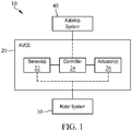
- FIG. 1 illustrates an aircraft system 10 for utilizing information obtained from an aircraft avionics system, link, and/or data bus to control vibration imposed by rotors and/or the rotary wing system.
- Aircraft system 10 includes an AVC system (AVCS) 20 adapted to control vibration imposed by a rotor wing or rotor system 30 using information at least partially received from an aircraft avionics system 40.
- AVCS AVC system
- AVCS 20 is configured to sense, measure, or detect vibrations, receive real-time aircraft information from a data bus, link, or avionics system 40, adjust algorithm control parameters as a function of real-time aircraft information, calculate a force command using the adjusted algorithm parameters, and generate a force that reduces vibrations imposed by rotor system 30, thereby actively counteracting aircraft vibration.
- AVCS 20 includes one or more sensors 22, a controller 24, and one or more actuators 26.
- sensors 22 of AVCS 20 is adapted to detect or measure vibration imposed upon aircraft components by rotor system 30.
- Sensors 22 are configured to measure and detect vibration information and send the vibration information obtained from rotor system 30 to controller 24 for use in an algorithm for actively generating a vibration canceling force command.
- controller 24 processes the vibration data received from sensors 22, modifies the vibration data and/or algorithm parameters via real-time aircraft information received from avionics system 40, and automatically outputs control commands to actuators 26. Actuators 26 may then, in response to receiving the control command, generate a vibration canceling force.
- controller 24 includes an algorithm for calculating a vibration canceling force which is adaptive to real-time aircraft information received from avionics system 40 and/or include algorithm control parameters adaptive to real-time aircraft information received from avionics system 40. This advantageously provides improved vibration control at steady state and transient flight conditions, as vibration profiles may vary greatly between such conditions.
- sensors 22 include accelerometers configured to measure vibrations of the fuselage, rotors, rotary wings, or structures or portions of the aircraft exhibiting vibrations imposed by rotor system 30.
- Controller 24 is configured to process the vibration data received from sensors 22 and output force commands or control commands to actuators 26.
- actuators 26 are configured to generate a vibration canceling force via the force commands output from controller 24.
- Actuators 26 include any suitable electromechanical device configured to generate forces for canceling vibrations imposed by rotor system 30.
- actuators 26 include resonant actuators having a natural resonant frequency and a resonant actuator control system with a command input for receiving a force command or command signal from controller 24.
- actuators 26 include one or more linear actuators, circular actuators (e.g., circular force generator (CFGs)), or hub mounted vibration systems (HMVS).
- Actuators 26 are disposed or positioned at any suitable location within an aircraft for controlling and/or canceling vibrations.
- actuators 26 are disposed in and/or attached to portions of the fuselage structure, the fuselage/rotor interface, each rotor blade, combinations thereof, or any other suitable portion or location within the aircraft.
- controller 24 of AVCS 20 is adapted to receive real-time aircraft information directly from avionics system 40, in addition to vibration data from sensors 22.
- controller 24 receives real-time aircraft information prior to processing vibration data from sensors 22.
- controller 24 receives real-time aircraft information prior to generating the force command and outputting the force command signal to actuators 26.
- Controller 24 is configured to use the real-time aircraft information received from avionics system 40 for improving performance of AVCS 20, as vibration may vary greatly during transition from low to high forward air speeds and between steady state and transient conditions.
- Real-time aircraft information received from avionics system 40 is used to adjust controller 24 algorithm parameters and/or weighting matrices used in the control algorithm as a function of real-time aircraft information to improve the steady state and transient performance of AVCS 20.
- controller 24 is adapted to simultaneously receive both vibration information from sensors 22 and real-time aircraft information from avionics system 40.
- avionics system 40 includes a data bus or data link having one or more physical and electrical interfaces. In some aspects, avionics system 40 includes a two-wire data bus and data protocol to support an aircraft's avionics local area network (LAN). In some aspects, avionics system 40 includes an aircraft data bus specified by ARINC 429, MIL-STD-1553, RS422, or any other suitable standard or protocol for aircraft data busses.
- avionics system 40 is configured to communicate real-time aircraft information directly to controller 24, such information includes forward air speed, rotor speed, engine torque, pitch, yaw, roll, altitude, relative altitude (e.g., height above ground), aircraft weight, weight on wheels, remaining fuel, glass cockpit mode (i.e., the introduction of Flight Management Systems (FMS) to help monitor and control the aircraft), first derivatives thereof, second derivatives thereof, combinations thereof, or any other pertinent information regarding the condition of the aircraft or flight information.
- FMS Flight Management Systems
- Aircraft A includes an improved AVCS 20 configured to receive real-time aircraft information from avionics system 40, and provide improved vibration control that is more adaptive to aircraft and flight conditions, such as low and high forward air speeds.
- aircraft A includes one or more fixed or rotary wings W.
- AVCS 20 includes one or more sensors 22, one or more actuators 26, and a controller 24.
- AVCS 20 is configured to input real-time aircraft information from an onboard data bus or avionics system 40 and provide an improved, modified, and adaptive force control algorithm for controlling vibration imposed from rotor system 30.
- real-time aircraft information obtained from avionics system 40 is used to modify weighting matrices and/or other parameters used in the control algorithm.
- vibration profiles may vary between low and high forward air speeds
- real-time aircraft information such as aircraft forward air speed, maneuver, whether the aircraft is hovering, rotor speed, engine torque, collective, pitch, yaw, roll, altitude, relative altitude, combinations thereof, and/or any other aircraft data transmitted via avionics system 40 are used to determine different parameters used within the force command algorithm for providing improved vibration control within the aircraft, that is more adaptive to the performance state of aircraft A.
- sensors 22 are placed over different portions of the aircraft fuselage or aircraft wings W.
- Actuators 26 are disposed in various locations of aircraft A, including for example being disposed over portions of the fuselage, wings (blades) W, and/or rotors of rotor system 30.
- controller 24 includes a physical device, such as a computer disposed within a portion of the aircraft fuselage. It is contemplated that in some aspects, controller 24 includes multiple computers disposed at various locations within aircraft A.
- Sensors 22, actuators 26, and avionics system 40 are each in communication with controller 24.
- data busses, wires, and physical and/or electrical interfaces facilitate communication therebetween.
- Figure 3 is one embodiment of an AVC device, such as a controller 50 of an AVCS.
- Controller includes for example a first interface 52 and a second interface 54.
- First and second interfaces 52 and 54 include physical and/or electrical interfaces configured for sending and receiving information.
- first and second interfaces 52 and 54 include signaling interfaces, such as a transmit (Tx) or Receive (Rx) interfaces, which are used for exchanging information.
- first interface 52 is configured to receive or input vibration information from sensors (e.g., 22, Figure 1 ).
- first interface 52 is also configured to receive or input real-time aircraft information 62 from an onboard data bus or avionics system (e.g., 40, Figure 1 ).
- Table 1 below contains non-limiting representative examples of real-time aircraft information 62 which may be received individually or in combination from a data bus or avionics system and optionally stored in controller 50.
- a first and/or a second derivative of the information contained in the table below are received from avionics system.
- the first or second derivative information can also be calculated in the controller. For example, velocity and acceleration (e.g., first and second derivatives of forward speed) may also be transmitted across first interface 52 to controller 50.
- Table 1 contains non-limiting representative examples of real-time aircraft information 62 which may be received individually or in combination from a data bus or avionics system and optionally stored in controller 50.
- a first and/or a second derivative of the information contained in the table below are received from avionics system.
- the first or second derivative information can also be calculated in the controller.
- velocity and acceleration e.g., first and second derivatives of forward speed
- Table 1 Examples of Aircraft Information Receivable from Data Bus or Avionics System Forward Air Speed (velocity, acceleration) Rotor Speed Engine Torque Collective Aircraft Center of Gravity Pitch, Yaw, Roll Altitude Relative Altitude (e.g., height above ground) Aircraft Weight Weight on Wheels Glass Cockpit Mode
- the real-time aircraft information 62 above is used to improve the steady state and transient performance of AVCS via adjusting control parameters and/or a control algorithm as a function of real-time aircraft information.
- controller 50 is adapted to detect changes in real-time aircraft information 62.
- controller 50 detects change in transient state as a function of aircraft information 62.
- Using real-time aircraft information 62 allows controller 50 to provide pre-programmed responses to changes in real-time aircraft information 62, trigger adjustment of control parameters and generate one more force commands, thereby ensuring the controller 50 provides near-instantaneous flight control based upon the flight condition.
- controller 50 also includes a force command generation module 56.
- Force command generation module 56 is configured to receive both sensor and real-time aircraft information and generate a force command. The force command is output to one or more actuators via second interface 54 for generating the vibration canceling force.
- force command generation module 56 includes a control algorithm 58.
- control algorithm 58 includes a least mean square (LMS) algorithm, model, and/or approach to vibration control.
- LMS least mean square
- algorithm 58 is not limited to LMS methodology and other algorithms and/or vibration modeling calculations may be used and provided.
- Control algorithm 58 processes and uses control parameters 60 and real-time aircraft information 62.
- Control parameters 60 include parameters used in various algorithm 58 methodologies and/or modeling calculations that may be adapted, tweaked, adjusted, transformed and/or otherwise modified using real-time aircraft information 62 as indicated in broken lines.
- Control parameters 60 includes LMS adaptation rate, LMS leak parameter, LMS sensor weighting matrix, LMS actuator weighting matrix, accelerometer de-modulation band-pass filter frequency bandwidth, accelerometer low pass filter break frequency or a combination thereof for calculating and generating a force command.
- One or more control parameters 60 are modified or adjusted as a function of real-time aircraft information 62.
- Table 2 below contains examples of control parameters 60 used within algorithm 58, which may be adjusted as a function of real-time aircraft information 62.
- Table 2 Examples of Algorithm Control Parameters Adjusted as a Function of Real-Time Aircraft Information LMS adaptation rate Sensor weighting matrix Force (e.g., actuator effort) weighting matrix Adaptive algorithm updated parameters Band-pass break frequencies Algorithm update low pass filter break frequency Accelerometer de-modulation low pass filter Table 2.
- Sensor weighting matrix Force e.g., actuator effort
- control parameters 60 are derived from vibration information obtained via sensors (e.g., 22, Figure 1 ) and optionally stored in a database for use in algorithm 58.
- Control parameters 60 are may derived either in real time and/or periodically.
- Control parameters 60 are modified or adjusted based upon real-time aircraft information 62 directly received from data bus or avionics system (e.g., 40, Figure 1 ).
- Real-time aircraft information 62 is derived from information regarding the aircraft or flight condition, such as the information previously described in Table 1, and optionally stored in a database for use in algorithm 58.
- control parameters 60 are adjusted in real time or periodically as a function of real-time aircraft information 62.
- an AVCS incorporating novel controller 50 is adaptive for reacting quickly to perceived changes in real-time aircraft information, such as when the aircraft is speeding up or slowing down. This improves vibration control as a function of flight condition or aircraft condition, which is derived using real-time aircraft information 62.
- real-time aircraft information transmitted and/or communicated to controller 50 via data bus is collected from and/or linked to a pilot's control stick. That is, as the pilot moves the control stick to speed up, slow down, maneuver, or otherwise change aircraft/flight information, the data bus or avionics system transmits such information immediately and directly to controller 50. Such data is also known as the "collective.” Controller 50 then uses such information to automatically adjust control parameters 60 used within algorithm 58 as a function of real-time aircraft information 62. As the aircraft speeds up or slows down, controller 50 reacts more quickly to control vibration levels.
- data bus e.g., avionics system 40, Figure 1
- real-time aircraft information comprises one or more data information inputs, wherein the real-time aircraft information is selected from the group consisting of forward air speed, collective, engine torque, rotor speed, pitch, yaw, roll, altitude, relative altitude, aircraft weight, weight on wheels, aircraft center of gravity, glass cockpit mode and combinations thereof. This includes the first and/or second derivative of some selected information
- algorithm 58 includes an LMS algorithm or methodology utilizing measured vibration from sensors (e.g., 22, Figure 1 ).
- Algorithm 58 is configured to generate force commands communicated to actuators (e.g., 26, Figure 1 ).
- actuators e.g., 26, Figure 1
- control parameters 60 including weighting matrices used in LMS algorithm
- J k is the cost function
- E k is the de-modulated error signal in the frequency domain (e.g., error signal obtained from sensors, such as accelerometers)
- E k H is a Hermitian matrix of E k (e.g., a complex conjugate transpose of E k );
- Q is a weighting matrix for the error signal;
- U k is the de-modulated actuator signal in the frequency domain;
- U k H is a Hermitian matrix of U k
- R is a weighting matrix on actuator effort (e.g., force).
- Sensor and actuator weighting may be used with an adaptive vibration control algorithm such as steepest descent principal component or Newton-Raphson algorithm, although not shown.
- control parameters 60 include sensor weighting matrix Q and actuator weighting matrix R as well as parameters such as an LMS adaptation rate, leak parameter, accelerometer de-modulation band-pass filter frequency bandwidth, or accelerometer low pass filter break frequency.
- Control parameters 60 are updated, modified, or adjusted as a function of real-time aircraft information 62, such as aircraft forward air speed. This is advantageous as the nature of helicopter vibration changes as a function of forward speed.
- Eq. (2) may be de-modulated as follows in Equations (3) and (4), into real and imaginary parts of an accelerometer transfer function at frequency f: E C + E C cos 4 ⁇ f t + E S sin 4 ⁇ f t and ; E S + E C sin 4 ⁇ f t + E S cos 4 ⁇ f t
- e(t) is the accelerometer time-domain signal derived from portions of a tachometer signal
- E C and E S are real and imaginary parts, respectively, of the accelerometer transfer function at frequency, f.
- Accelerometer de-modulation low pass filter and band-pass break frequencies are modified as a function of real-time aircraft information, such as information contained in Table 1, and derivatives thereof. It should be appreciated that other variations of algorithm 58, and not just LMS, may be used and are contemplated herein. Algorithm parameters, variables, or input are adjustable as a function of aircraft/flight information.
- vibration control is provided by an AVCS having an AVC device, such as a controller.
- sensor information is received.
- sensor information includes vibration information received from one or more accelerometers and/or information from one or more tachometers.
- AVCS includes a controller adapted to receive sensor information across an interface.
- AVCS includes a controller adapted to receive real-time aircraft information across an interface.
- the interface for receiving the sensor information and the real-time aircraft information is the same or different.
- Sensor information and real-time aircraft information are received in real time, periodically, simultaneously, combinations thereof, and/or at different and mutually exclusive time intervals.
- real-time aircraft information is communicated from an onboard data bus.
- controller detects large or small changes in real-time aircraft information, which may be indicative of an aircraft moving between steady state and transient performance.
- FIG. 5 A non-limiting example of the control parameter adjustment is illustrated in FIG. 5 where the adaptation rate versus forward air speed is modeled.
- the controller is adapted to generate force commands as a function of changes in flight and/or aircraft conditions using real-time aircraft information.
- control parameters are adjusted.
- control parameters e.g., provided in Table 2
- real-time aircraft information e.g., provided in Table 1.
- adjusting control parameters as a function of real-time aircraft information provides improved vibration control at steady state and transient performance, as control parameters are more indicative of actual aircraft and/or flight condition(s).
- Control parameters are used in a control algorithm of controller.
- Control algorithm is configured to calculate a force command communicated to actuators.
- AVCS includes actuators adapted to receive the force command from controller, and generate a vibration canceling force.
- controller uses adjusted control parameters and quickly adapts to flight conditions at low forward air speeds (e.g., ⁇ 100 knots) when flare and/or other large transients occur.
- controller uses adjusted control parameters and slowly adapts at high forward air speeds (e.g., > 100 knots) for improving steadiness during steady flight conditions.
- Controller is configured to adapt quickly (e.g., adjust control parameters) where changes in aircraft transients occur. Controller detects such changes using information communicated from avionics system. For example, controller quickly adapts to large changes in forward air speed, engine torque, the collective, altitude, pitch, roll, yaw, combinations thereof, and/or large changes in rotor speed.
- controller In block 76, controller generates a force command and outputs the force command to one or more actuators.
- actuators receive control commands calculated and determined using parameters which have been adjusted as a function of flight or aircraft condition. This provides improved vibration control.
- the method disclosed in Figure 4 includes one or more optional steps.
- the controller e.g., 24 Figure 1 , 50 Figure 3
- the controller may be configured to monitoring one or more types of real-time aircraft information, and implementing AVC via the steps illustrated in Figure 4 more quickly and/or more slowly in response to the monitored information.
- a controller monitors real-time aircraft information such as, for example only, forward air speed. As the monitored air speed transitions to lower air speeds (e.g., ⁇ 100 knots), the AVC device and/or system is adapted to respond and implement AVC per the method disclosed in Figure 4 more quickly.
- the AVC device and/or system is adapted to respond and implement AVC per the method disclosed in Figure 4 more slowly.
- Any type real-time aircraft information other than forward air speed such as information provided in Table 1 above, may be monitored as described herein and used to implement AVC more quickly or more slowly during transients or transient conditions (e.g., large or small changes to the monitored information). That is, AVC is implemented at various, different time intervals (e.g., more or less slowly/quickly) based upon the monitored real-time aircraft information.
- a controller e.g., 24 Figure 1 , 50 Figure 3
- a controller is configured and adapted to perform the optional steps of monitoring and receiving a first type of real-time aircraft information and comparing that information with at least one other type of real-time aircraft information received from avionics system, or data bus.
- multiple types of real-time aircraft information are monitored and compared at controller.
- the AVC device and/or system may then implement AVC based upon the monitored and compared information via the steps illustrated in Figure 4 .
- rotor speed and forward air speed are monitored and compared.
- AVC per the method disclosed in Figure 4 is implemented more quickly or more slowly via the AVC device and/or system based upon such information.
- the AVC device and/or system react quickly and implement AVC more quickly.
- the air speed changes by a large amount e.g., either positively or negatively
- the AVC device and/or system reacts more slowly and implements AVC more slowly. That is, AVC is implemented at various, different time intervals (e.g., more or less slowly/quickly) based upon the monitored and compared information.
- Any suitable type information other than air speed and rotor speed such as information provided in Table 1 above, may be monitored and compared as described herein and used to implement AVC more quickly or more slowly during transients (e.g., large or small changes to the monitored and compared information).
- AVC devices and AVCSs including AVC devices, as described herein, provide adaptive algorithm control parameters, and therefore, adaptive algorithms, which are modified based on a function of aircraft and/or flight information.
- This improves the steady state and transient performance of the AVCS, as vibration control is adjusted using real-time aircraft information such as forward air speed, altitude, engine torque, rotor speed, etc.
- Embodiments as disclosed herein may provide one or more of the following beneficial technical effects: reduced cost; reduced weight; improved vibration control during steady state and transient performance using adaptive algorithm and/or adaptive algorithm control parameters which have been adjusted as a function of real-time aircraft information.
Description
- The present subject matter relates generally to devices, systems, and methods for controlling vibration. More particularly the present subject matter relates to devices, systems, and related methods for actively controlling vibration, for example particularly in aircraft, such as rotary winged aircraft.
- Various types of aircraft experience vibrations during operation. Such vibrations are particularly troublesome in rotary winged aircraft, such as helicopters, as vibrations transmitted by large rotors can contribute to fatigue and wear on equipment, materials, and occupants within the aircraft. Vibrations can damage the actual structure and components of the aircraft, as well as contents disposed within the aircraft. This increases costs associated with maintaining and providing rotary winged aircraft, such as costs associated with inspecting and replacing parts within the aircraft, which may become damaged during vibration.
- Conventional methods of controlling vibration within an aircraft include using passive devices and/or systems, which are tuned relative to the operating frequency of the aircraft rotor. In addition to adding large amounts of weight to the aircraft, passive devices and/or systems are inefficient. More effective methods of controlling vibration within an aircraft include active devices and/or systems, which actively apply a control force to counteract forces imposed by aircraft vibration.
- One problem associated with conventional active vibration control devices and/or systems, is that such systems fail to account for different vibration profiles occurring when an aircraft is at steady state versus in transient performance and/or at low and high forward air speeds. That is, currently available active vibration control devices and systems fail to account for changes to other aircraft information, such as forward air speed, rotor speed, altitude, etc., when generating control force commands, as those changes occur in real-time. Currently there is not an active vibration control device, system, or related method providing real-time modification of control parameters based upon real-time aircraft information.
-
U.S. Patent Publication No. 2011/303784A1 discloses an adaptive reference model algorithm that uses a gain scheduling feature combined with a customized Least-Squares routine as an adaptive method for adjusting feedback control so as to account for variations in Transfer Function (G), thereby optimizing the effectiveness of the Active Vibration Control (AVC) System. According to the disclosure, the Least-Squares routine identifies the transfer function in a background process without interruption of closed loop vibration control. According to the disclosure, this identification approach is accomplished without intentional interrogation of the AVC actuators and without intentional vibration level changes. According to the disclosure, for this adaptive control logic, the dynamic relationship between AVC actuators and AVC sensors is represented by a mathematical model of Transfer Function (G). According to the disclosure, the mathematical model of Transfer Function (G) is continuously updated by the Least-Squares routine. A feedback gain (H) is computed from the mathematical model of Transfer Function (G), and the feedback gain (H) is updated each time the mathematical model of Transfer Function (G) is updated. -
PCT Patent Publication No. WO 2012/021202 A2 -
U.S. Patent Publication No. 2010/003133A1 discloses a dual, counter-rotating, coaxial rotor system provides individual control of an upper rotor system and a lower rotor system. The lower rotor control system and the upper rotor control system provide six controls or "knobs" to minimize or theoretically eliminate airframe vibration. In a dual, counter-rotating, coaxial rotor system, application of a HHC system to the two rotor systems individually but located on the common axis, will yield essentially complete vibration reduction because the 6 controls will suppress the 6 loads. - European Patent Publication No.
EP2538109A1 discloses a vibration reduction device according to the present invention includes: an elastic body; a dynamic mass; and a controllable mass. The dynamic mass is supported by an object of vibration reduction through the elastic body. The actuator causes the controllable mass to move with respect to the dynamic mass. Such a vibration reduction device can vary the frequency and the amplitude at which the dynamic mass vibrates with respect to the object of vibration reduction by causing the controllable mass to move appropriately with respect to the dynamic mass, thereby enabling the vibration of the object of vibration reduction to be reduced more reliably. In addition, such a vibration reduction device can reduce vibration of a certain frequency of the object of vibration reduction even when the controllable mass is fixed with respect to the dynamic mass. -
U.S. Patent No. 4,953,098A discloses in an X-Wing aircraft a dynamic higher harmonic control (HHC) system addresses the vibration which typifies a very rigid rotor and is implemented in two ways--a scheduled HHC and an active HHC. A scheduled HHC is located within the quadruple redundant portion of the flight control computers (FCC). This includes look-up maps for the second through fifth harmonic coefficients of the control equation as a function of airspeed and lift for rotary wing (RW) operation, and as a function of rotor speed for conversion (CV) operation. These are added to the collective and cyclic terms of the control equation and implemented through the pneumatic control valve (PCV) actuators. This flight critical portion of the HHC maintains vibration loads within structural limits. An active HHC, implemented in a dual redundant configuration, is added primarily to enhance vibration control during maneuver conditions and during conversions. It monitors vibrations at selected locations and in selected axes of the vehicle and generates corrective factors, which are added to the scheduled coefficients. The active HHC, representing a significant computational burden, is implemented in a separate dual processor computer section, complete with its own input/output signal processing. - Accordingly, there is a need for improved devices, systems, and methods for actively controlling aircraft vibration as the aircraft moves between transient and steady state conditions in real-time.
- In accordance with the disclosure provided herein, novel and improved active vibration control (AVC) methods are provided. In some aspects, improved AVC methods utilize control parameters that are adaptive or adjusted as a function of real-time aircraft information, including information relating to aircraft and/or flight condition(s).
- A method of controlling vibration within an aircraft using a vibration controller according to claim 1 is provided, the method comprising steps which are summarized below:
- a) receiving vibration information from at least one sensor;
- b) receiving real-time aircraft information from an avionics system;
- c) adjusting at least one control parameter produced by the vibration controller as a function of the real-time aircraft information;
- d) calculating a force command using at least one of the adjusted algorithm control parameters; and
- e) generating and outputting the force command that reduces vibrations imposed by the rotor system of the aircraft.
-
-
Figure 1 is a block diagram illustrating an active vibration control (AVC) system (AVCS) according to one aspect of the subject matter described herein. -
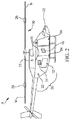
Figure 2 is a perspective view of a rotary winged aircraft with an AVCS according to one aspect of the subject matter described herein. -
Figure 3 is a block diagram illustrating an AVC device for an AVCS according to one aspect of the subject matter described herein. -
Figure 4 is a flow chart illustrating exemplary steps for providing active vibration control according to one aspect of the subject matter described herein. -
Figure 5 is an illustrative plot of adaptation rate (convergence speed) versus forward air speed. - The subject matter disclosed herein is directed to novel active vibration control (AVC) methods for use within a rotary wing aircraft. AVC devices and AVCS provided herein include a controller adapted to receive aircraft information and adjust at least one control parameter as a function of the real-time aircraft information. In some aspects, the real-time aircraft information is directly received from a data bus or avionics system. Such information is used to improve the steady state and transient performance of an AVC device or AVCS. In some aspects, changes in real-time aircraft information may indicate transient conditions. The controller is also adapted to detect changes in real-time aircraft information, thereby rapidly adapting vibration control to the flight condition or condition of the aircraft.
- In some aspects, the avionics system is configured to collect and communicate real-time aircraft information to the controller via a data bus system described or provided by a standard selected from one of ARINC 429, MIL-STD-1553, or RS422.
- In some aspects, real-time aircraft information used by an AVC device or system includes forward air speed, rotor speed, engine torque pitch, yaw, roll, altitude, relative altitude, aircraft weight, weight on wheels, aircraft center of gravity, engine torque, collective, whether an aircraft is operable in glass cockpit mode, acceleration, and/or velocity. In one aspect real-time aircraft information comprises one or more data information inputs, wherein the real-time aircraft information is selected from the group consisting of forward air speed, rotor speed, pitch, yaw, roll, altitude, relative altitude, aircraft weight, weight on wheels, aircraft center of gravity, glass cockpit mode and combinations thereof. This includes the first and/or second derivative of some selected information;
- In some aspects, control parameters used in generating a force command are adjusted by the controller as a function of the real-time aircraft information. In some aspects, control parameters include a sensor weighting matrix, an actuator weighting matrix. a parameter of an adaptive vibration controller such as a least mean squared (LMS) control mechanism or algorithm, a parameter of a low-pass filter mechanism, an LMS adaptation rate, an accelerometer demodulation low-pass filter parameter, and/or a band-pass break frequency.
- In some aspects, a first type of real-time aircraft information is monitored and/or compared with other types of real-time aircraft information. For example, a controller monitors and/or compares rotor speed, forward air speed, and other information. Active vibration control is implemented with quicker reaction time than already provided for or more slowly than already provided for via the AVCS based upon such information and comparisons thereof. In some aspects, active vibration control is implemented more slowly via the AVCS at higher forward air speeds. In some aspects, active vibration control is implemented more quickly via the AVC system at lower forward air speeds.
-
Figures 1 to 4 illustrate various views and/or features associated with AVC devices, AVCS, and related methods for controlling vibration in aircraft, namely, rotary wing aircraft. In some aspects, AVC systems, devices, and related methods described herein are adapted for use in rotary winged aircraft (i.e., rotorcraft), fixed-wing aircraft, tiltrotor aircraft, as well as hybrid aircraft being part rotorcraft and part road vehicle. -
Figure 1 illustrates anaircraft system 10 for utilizing information obtained from an aircraft avionics system, link, and/or data bus to control vibration imposed by rotors and/or the rotary wing system.Aircraft system 10 includes an AVC system (AVCS) 20 adapted to control vibration imposed by a rotor wing orrotor system 30 using information at least partially received from anaircraft avionics system 40. In some aspects,AVCS 20 is configured to sense, measure, or detect vibrations, receive real-time aircraft information from a data bus, link, oravionics system 40, adjust algorithm control parameters as a function of real-time aircraft information, calculate a force command using the adjusted algorithm parameters, and generate a force that reduces vibrations imposed byrotor system 30, thereby actively counteracting aircraft vibration. - In some aspects,
AVCS 20 includes one ormore sensors 22, acontroller 24, and one ormore actuators 26. As indicated in broken lines,sensors 22 ofAVCS 20 is adapted to detect or measure vibration imposed upon aircraft components byrotor system 30.Sensors 22 are configured to measure and detect vibration information and send the vibration information obtained fromrotor system 30 tocontroller 24 for use in an algorithm for actively generating a vibration canceling force command. In some aspects,controller 24 processes the vibration data received fromsensors 22, modifies the vibration data and/or algorithm parameters via real-time aircraft information received fromavionics system 40, and automatically outputs control commands to actuators 26.Actuators 26 may then, in response to receiving the control command, generate a vibration canceling force. - In some aspects,
controller 24 includes an algorithm for calculating a vibration canceling force which is adaptive to real-time aircraft information received fromavionics system 40 and/or include algorithm control parameters adaptive to real-time aircraft information received fromavionics system 40. This advantageously provides improved vibration control at steady state and transient flight conditions, as vibration profiles may vary greatly between such conditions. - In some aspects,
sensors 22 include accelerometers configured to measure vibrations of the fuselage, rotors, rotary wings, or structures or portions of the aircraft exhibiting vibrations imposed byrotor system 30.Controller 24 is configured to process the vibration data received fromsensors 22 and output force commands or control commands toactuators 26. In some aspects,actuators 26 are configured to generate a vibration canceling force via the force commands output fromcontroller 24.Actuators 26 include any suitable electromechanical device configured to generate forces for canceling vibrations imposed byrotor system 30. In some aspects,actuators 26 include resonant actuators having a natural resonant frequency and a resonant actuator control system with a command input for receiving a force command or command signal fromcontroller 24. In other aspects,actuators 26 include one or more linear actuators, circular actuators (e.g., circular force generator (CFGs)), or hub mounted vibration systems (HMVS).Actuators 26 are disposed or positioned at any suitable location within an aircraft for controlling and/or canceling vibrations. For example, actuators 26 are disposed in and/or attached to portions of the fuselage structure, the fuselage/rotor interface, each rotor blade, combinations thereof, or any other suitable portion or location within the aircraft. - Notably, as indicated in broken lines,
controller 24 ofAVCS 20 is adapted to receive real-time aircraft information directly fromavionics system 40, in addition to vibration data fromsensors 22. In some aspects,controller 24 receives real-time aircraft information prior to processing vibration data fromsensors 22. In some aspects,controller 24 receives real-time aircraft information prior to generating the force command and outputting the force command signal toactuators 26.Controller 24 is configured to use the real-time aircraft information received fromavionics system 40 for improving performance ofAVCS 20, as vibration may vary greatly during transition from low to high forward air speeds and between steady state and transient conditions. - Real-time aircraft information received from
avionics system 40 is used to adjustcontroller 24 algorithm parameters and/or weighting matrices used in the control algorithm as a function of real-time aircraft information to improve the steady state and transient performance ofAVCS 20. In some aspects,controller 24 is adapted to simultaneously receive both vibration information fromsensors 22 and real-time aircraft information fromavionics system 40. - In some aspects,
avionics system 40 includes a data bus or data link having one or more physical and electrical interfaces. In some aspects,avionics system 40 includes a two-wire data bus and data protocol to support an aircraft's avionics local area network (LAN). In some aspects,avionics system 40 includes an aircraft data bus specified by ARINC 429, MIL-STD-1553, RS422, or any other suitable standard or protocol for aircraft data busses. In some aspects,avionics system 40 is configured to communicate real-time aircraft information directly tocontroller 24, such information includes forward air speed, rotor speed, engine torque, pitch, yaw, roll, altitude, relative altitude (e.g., height above ground), aircraft weight, weight on wheels, remaining fuel, glass cockpit mode (i.e., the introduction of Flight Management Systems (FMS) to help monitor and control the aircraft), first derivatives thereof, second derivatives thereof, combinations thereof, or any other pertinent information regarding the condition of the aircraft or flight information. - Referring now to
Figure 2 , one example is provided of an aircraft generally designated A, without limitation. Aircraft A includes animproved AVCS 20 configured to receive real-time aircraft information fromavionics system 40, and provide improved vibration control that is more adaptive to aircraft and flight conditions, such as low and high forward air speeds. In some aspects, aircraft A includes one or more fixed or rotary wings W. As noted above,AVCS 20 includes one ormore sensors 22, one ormore actuators 26, and acontroller 24. -
AVCS 20 is configured to input real-time aircraft information from an onboard data bus oravionics system 40 and provide an improved, modified, and adaptive force control algorithm for controlling vibration imposed fromrotor system 30. In some aspects, real-time aircraft information obtained fromavionics system 40 is used to modify weighting matrices and/or other parameters used in the control algorithm. As vibration profiles may vary between low and high forward air speeds, real-time aircraft information such as aircraft forward air speed, maneuver, whether the aircraft is hovering, rotor speed, engine torque, collective, pitch, yaw, roll, altitude, relative altitude, combinations thereof, and/or any other aircraft data transmitted viaavionics system 40 are used to determine different parameters used within the force command algorithm for providing improved vibration control within the aircraft, that is more adaptive to the performance state of aircraft A. - Using real-time aircraft information communicated from
avionics system 40 for adjusting control algorithm and/or parameters used within control algorithm as a function of real-time aircraft information improves performance at both steady state and transient flight conditions. In some aspects,sensors 22 are placed over different portions of the aircraft fuselage or aircraftwings W. Actuators 26 are disposed in various locations of aircraft A, including for example being disposed over portions of the fuselage, wings (blades) W, and/or rotors ofrotor system 30. In some aspects,controller 24 includes a physical device, such as a computer disposed within a portion of the aircraft fuselage. It is contemplated that in some aspects,controller 24 includes multiple computers disposed at various locations withinaircraft A. Sensors 22,actuators 26, andavionics system 40 are each in communication withcontroller 24. In some aspects, data busses, wires, and physical and/or electrical interfaces facilitate communication therebetween. -
Figure 3 is one embodiment of an AVC device, such as acontroller 50 of an AVCS. Controller includes for example afirst interface 52 and a second interface 54. First andsecond interfaces 52 and 54 include physical and/or electrical interfaces configured for sending and receiving information. In some aspects, first andsecond interfaces 52 and 54 include signaling interfaces, such as a transmit (Tx) or Receive (Rx) interfaces, which are used for exchanging information. In some aspects,first interface 52 is configured to receive or input vibration information from sensors (e.g., 22,Figure 1 ). Notably,first interface 52 is also configured to receive or input real-time aircraft information 62 from an onboard data bus or avionics system (e.g., 40,Figure 1 ). Table 1 below contains non-limiting representative examples of real-time aircraft information 62 which may be received individually or in combination from a data bus or avionics system and optionally stored incontroller 50. In some aspects, a first and/or a second derivative of the information contained in the table below are received from avionics system. The first or second derivative information can also be calculated in the controller. For example, velocity and acceleration (e.g., first and second derivatives of forward speed) may also be transmitted acrossfirst interface 52 tocontroller 50.Table 1. Table 1: Examples of Aircraft Information Receivable from Data Bus or Avionics System Forward Air Speed (velocity, acceleration) Rotor Speed Engine Torque Collective Aircraft Center of Gravity Pitch, Yaw, Roll Altitude Relative Altitude (e.g., height above ground) Aircraft Weight Weight on Wheels Glass Cockpit Mode - The real-time aircraft information 62 above is used to improve the steady state and transient performance of AVCS via adjusting control parameters and/or a control algorithm as a function of real-time aircraft information. In some aspects,
controller 50 is adapted to detect changes in real-time aircraft information 62. Thus,controller 50 detects change in transient state as a function of aircraft information 62. Using real-time aircraft information 62 allowscontroller 50 to provide pre-programmed responses to changes in real-time aircraft information 62, trigger adjustment of control parameters and generate one more force commands, thereby ensuring thecontroller 50 provides near-instantaneous flight control based upon the flight condition. - In some aspects,
controller 50 also includes a forcecommand generation module 56. Forcecommand generation module 56 is configured to receive both sensor and real-time aircraft information and generate a force command. The force command is output to one or more actuators via second interface 54 for generating the vibration canceling force. - In one non-limiting example, force
command generation module 56 includes a control algorithm 58. In some aspects, control algorithm 58 includes a least mean square (LMS) algorithm, model, and/or approach to vibration control. However, algorithm 58 is not limited to LMS methodology and other algorithms and/or vibration modeling calculations may be used and provided. - Control algorithm 58 processes and uses
control parameters 60 and real-time aircraft information 62.Control parameters 60 include parameters used in various algorithm 58 methodologies and/or modeling calculations that may be adapted, tweaked, adjusted, transformed and/or otherwise modified using real-time aircraft information 62 as indicated in broken lines.Control parameters 60 includes LMS adaptation rate, LMS leak parameter, LMS sensor weighting matrix, LMS actuator weighting matrix, accelerometer de-modulation band-pass filter frequency bandwidth, accelerometer low pass filter break frequency or a combination thereof for calculating and generating a force command. One ormore control parameters 60 are modified or adjusted as a function of real-time aircraft information 62. Table 2 below contains examples ofcontrol parameters 60 used within algorithm 58, which may be adjusted as a function of real-time aircraft information 62.Table 2: Examples of Algorithm Control Parameters Adjusted as a Function of Real-Time Aircraft Information LMS adaptation rate Sensor weighting matrix Force (e.g., actuator effort) weighting matrix Adaptive algorithm updated parameters Band-pass break frequencies Algorithm update low pass filter break frequency Accelerometer de-modulation low pass filter Table 2. - In some aspects,
control parameters 60 are derived from vibration information obtained via sensors (e.g., 22,Figure 1 ) and optionally stored in a database for use in algorithm 58.Control parameters 60 are may derived either in real time and/or periodically.Control parameters 60 are modified or adjusted based upon real-time aircraft information 62 directly received from data bus or avionics system (e.g., 40,Figure 1 ). Real-time aircraft information 62 is derived from information regarding the aircraft or flight condition, such as the information previously described in Table 1, and optionally stored in a database for use in algorithm 58. In some aspects,control parameters 60 are adjusted in real time or periodically as a function of real-time aircraft information 62. Notably, an AVCS incorporatingnovel controller 50 is adaptive for reacting quickly to perceived changes in real-time aircraft information, such as when the aircraft is speeding up or slowing down. This improves vibration control as a function of flight condition or aircraft condition, which is derived using real-time aircraft information 62. - In some aspects, real-time aircraft information transmitted and/or communicated to
controller 50 via data bus (e.g.,avionics system 40,Figure 1 ) is collected from and/or linked to a pilot's control stick. That is, as the pilot moves the control stick to speed up, slow down, maneuver, or otherwise change aircraft/flight information, the data bus or avionics system transmits such information immediately and directly tocontroller 50. Such data is also known as the "collective."Controller 50 then uses such information to automatically adjustcontrol parameters 60 used within algorithm 58 as a function of real-time aircraft information 62. As the aircraft speeds up or slows down,controller 50 reacts more quickly to control vibration levels. Thus, in one aspect real-time aircraft information comprises one or more data information inputs, wherein the real-time aircraft information is selected from the group consisting of forward air speed, collective, engine torque, rotor speed, pitch, yaw, roll, altitude, relative altitude, aircraft weight, weight on wheels, aircraft center of gravity, glass cockpit mode and combinations thereof. This includes the first and/or second derivative of some selected information - As noted above, in some aspects algorithm 58 includes an LMS algorithm or methodology utilizing measured vibration from sensors (e.g., 22,
Figure 1 ). Algorithm 58 is configured to generate force commands communicated to actuators (e.g., 26,Figure 1 ). In order to make adjustments to the force command using an LMS algorithm, a finite set of data must first be collected and processed before an adjustment is made. Thus, the LMS algorithm may not respond well to changes in aircraft or flight condition. In order to improve vibration control, control parameters 60 (including weighting matrices used in LMS algorithm) are adjusted or modified as a function of real-time aircraft information 62. - In some aspects, algorithm 58 includes an LMS algorithm minimizing Equation (1), which is a cost function (J) at time step, k:

- In Eq. (1) above, Jk is the cost function; Ek is the de-modulated error signal in the frequency domain (e.g., error signal obtained from sensors, such as accelerometers); Ek H is a Hermitian matrix of Ek (e.g., a complex conjugate transpose of Ek); Q is a weighting matrix for the error signal; Uk is the de-modulated actuator signal in the frequency domain; Uk H is a Hermitian matrix of Uk, and R is a weighting matrix on actuator effort (e.g., force). Sensor and actuator weighting may be used with an adaptive vibration control algorithm such as steepest descent principal component or Newton-Raphson algorithm, although not shown.
- In some aspects,
control parameters 60 include sensor weighting matrix Q and actuator weighting matrix R as well as parameters such as an LMS adaptation rate, leak parameter, accelerometer de-modulation band-pass filter frequency bandwidth, or accelerometer low pass filter break frequency.Control parameters 60 are updated, modified, or adjusted as a function of real-time aircraft information 62, such as aircraft forward air speed. This is advantageous as the nature of helicopter vibration changes as a function of forward speed. -
Controller 50 is also adapted to implement a low pass filter. Parameters thereof are also adjustable as a function of real-time aircraft information. In some embodiments, accelerometer de-modulation low pass filter and band-pass break frequencies are adjusted or modified as a function of real-time aircraft information. For example, Equation (2) below is an example of a time domain error signal, where e(t) is an accelerometer time-domain signal.
- Eq. (2) may be de-modulated as follows in Equations (3) and (4), into real and imaginary parts of an accelerometer transfer function at frequency f:


- In Eq. (2) to (4) above, e(t) is the accelerometer time-domain signal derived from portions of a tachometer signal, and EC and ES are real and imaginary parts, respectively, of the accelerometer transfer function at frequency, f. Accelerometer de-modulation low pass filter and band-pass break frequencies are modified as a function of real-time aircraft information, such as information contained in Table 1, and derivatives thereof. It should be appreciated that other variations of algorithm 58, and not just LMS, may be used and are contemplated herein. Algorithm parameters, variables, or input are adjustable as a function of aircraft/flight information. Although the description herein is shown in a limited number of forms, it is not limited to just these forms but rather is amenable to various changes and modifications without departing from the scope thereof.
- Referring to
Figure 4 , a flow chart illustrating, without limitation, exemplary steps for providing active vibration control within an aircraft according to one aspect of the subject matter described herein is illustrated. In some aspects, vibration control is provided by an AVCS having an AVC device, such as a controller. Inblock 70, sensor information is received. In some aspects, sensor information includes vibration information received from one or more accelerometers and/or information from one or more tachometers. In some aspects and as previously described, AVCS includes a controller adapted to receive sensor information across an interface. - In block 72, real-time aircraft information is received. In some aspects and as previously described, AVCS includes a controller adapted to receive real-time aircraft information across an interface. The interface for receiving the sensor information and the real-time aircraft information is the same or different. Sensor information and real-time aircraft information are received in real time, periodically, simultaneously, combinations thereof, and/or at different and mutually exclusive time intervals. In some aspects, real-time aircraft information is communicated from an onboard data bus. In some aspects, controller detects large or small changes in real-time aircraft information, which may be indicative of an aircraft moving between steady state and transient performance. A non-limiting example of the control parameter adjustment is illustrated in
FIG. 5 where the adaptation rate versus forward air speed is modeled. In some aspects, the controller is adapted to generate force commands as a function of changes in flight and/or aircraft conditions using real-time aircraft information. - In block 74, control parameters are adjusted. In some aspects, control parameters (e.g., provided in Table 2) are adjusted as a function of real-time aircraft information (e.g., provided in Table 1). In some aspects, adjusting control parameters as a function of real-time aircraft information provides improved vibration control at steady state and transient performance, as control parameters are more indicative of actual aircraft and/or flight condition(s). Control parameters are used in a control algorithm of controller. Control algorithm is configured to calculate a force command communicated to actuators. AVCS includes actuators adapted to receive the force command from controller, and generate a vibration canceling force.
- In some aspects, controller uses adjusted control parameters and quickly adapts to flight conditions at low forward air speeds (e.g., < 100 knots) when flare and/or other large transients occur. In other aspects, controller uses adjusted control parameters and slowly adapts at high forward air speeds (e.g., > 100 knots) for improving steadiness during steady flight conditions. Controller is configured to adapt quickly (e.g., adjust control parameters) where changes in aircraft transients occur. Controller detects such changes using information communicated from avionics system. For example, controller quickly adapts to large changes in forward air speed, engine torque, the collective, altitude, pitch, roll, yaw, combinations thereof, and/or large changes in rotor speed.
- In block 76, controller generates a force command and outputs the force command to one or more actuators. Notably, actuators receive control commands calculated and determined using parameters which have been adjusted as a function of flight or aircraft condition. This provides improved vibration control.
- In some aspects, the method disclosed in
Figure 4 includes one or more optional steps. For example, in some aspects the controller (e.g., 24Figure 1 , 50Figure 3 ) may be configured to monitoring one or more types of real-time aircraft information, and implementing AVC via the steps illustrated inFigure 4 more quickly and/or more slowly in response to the monitored information. In some aspects, a controller monitors real-time aircraft information such as, for example only, forward air speed. As the monitored air speed transitions to lower air speeds (e.g., < 100 knots), the AVC device and/or system is adapted to respond and implement AVC per the method disclosed inFigure 4 more quickly. As the monitored air speed transitions to higher air speeds (e.g., > 100 knots), the AVC device and/or system is adapted to respond and implement AVC per the method disclosed inFigure 4 more slowly. Any type real-time aircraft information other than forward air speed, such as information provided in Table 1 above, may be monitored as described herein and used to implement AVC more quickly or more slowly during transients or transient conditions (e.g., large or small changes to the monitored information). That is, AVC is implemented at various, different time intervals (e.g., more or less slowly/quickly) based upon the monitored real-time aircraft information. - In other aspects, a controller (e.g., 24
Figure 1 , 50Figure 3 ) is configured and adapted to perform the optional steps of monitoring and receiving a first type of real-time aircraft information and comparing that information with at least one other type of real-time aircraft information received from avionics system, or data bus. In some aspects, multiple types of real-time aircraft information are monitored and compared at controller. The AVC device and/or system may then implement AVC based upon the monitored and compared information via the steps illustrated inFigure 4 . For example only and without limitation, in some aspects rotor speed and forward air speed are monitored and compared. AVC per the method disclosed inFigure 4 is implemented more quickly or more slowly via the AVC device and/or system based upon such information. In some aspects, where the speed of the main rotor changes by a larger amount (e.g., positively or negatively), the AVC device and/or system react quickly and implement AVC more quickly. Where the air speed changes by a large amount (e.g., either positively or negatively), the AVC device and/or system reacts more slowly and implements AVC more slowly. That is, AVC is implemented at various, different time intervals (e.g., more or less slowly/quickly) based upon the monitored and compared information. Any suitable type information other than air speed and rotor speed, such as information provided in Table 1 above, may be monitored and compared as described herein and used to implement AVC more quickly or more slowly during transients (e.g., large or small changes to the monitored and compared information). - Notably, AVC devices and AVCSs, including AVC devices, as described herein, provide adaptive algorithm control parameters, and therefore, adaptive algorithms, which are modified based on a function of aircraft and/or flight information. This improves the steady state and transient performance of the AVCS, as vibration control is adjusted using real-time aircraft information such as forward air speed, altitude, engine torque, rotor speed, etc. Embodiments as disclosed herein may provide one or more of the following beneficial technical effects: reduced cost; reduced weight; improved vibration control during steady state and transient performance using adaptive algorithm and/or adaptive algorithm control parameters which have been adjusted as a function of real-time aircraft information.
- While the present subject matter has been has been described herein in reference to specific aspects, features, and illustrative embodiments, it will be appreciated that the utility of the subject matter herein is not thus limited, but rather extends to and encompasses numerous other variations, modifications and alternative embodiments, as will suggest themselves to those of ordinary skill in the field of the present subject matter, based on the disclosure herein. Various combinations and sub-combinations of the structures and features described herein are contemplated and will be apparent to a skilled person having knowledge of this disclosure. Any of the various features and elements as disclosed herein may be combined with one or more other disclosed features and elements unless indicated to the contrary herein.
Claims (8)
- A method of providing active vibration control using a vibration controller (24,50) within an aircraft (A) having a rotor system, the method comprising:receiving vibration information from one or more sensors (22);receiving real-time aircraft information (62) from an avionics system (40);the method characterized in that the method further comprises adjusting in real time and/or periodically at least one algorithm control parameter (60) as a function of the real-time aircraft information (62) produced by the vibration controller (24, 50), the algorithm control parameter selected from the group consisting of a Least Mean Square (LMS) adaptation rate, a sensor weighting matrix, an actuator weighting matrix, an adaptive algorithm updated parameter, a band-pass break frequency, an algorithm update low pass filter break frequency, or an accelerometer de-modulation low pass filter;calculating a force command using the at least one adjusted algorithm control parameter; andgenerating and outputting the force command that reduces vibrations imposed by the rotor system (30).
- The method of claim 1, further comprising receiving the real-time aircraft information (62) which is received from an on board data bus.
- The method of claim 1, further comprising detecting changes in the real-time aircraft information (62).
- The method of claim 1, further comprising receiving the vibration information from one or more accelerometers.
- The method of claim 1, further comprising outputting the force command to one or more actuators (26).
- The method of claim 2, further comprising providing real-time aircraft information across the data bus by using a standard selected from one of ARINC 429, MIL-STD-1553, or RS422.
- The method of claim 1, further comprising selecting the real-time aircraft information (62) from the group consisting of forward air speed, rotor speed, pitch, yaw, roll, altitude, or relative altitude, aircraft weight, weight on wheels, aircraft center of gravity, glass cockpit mode and combinations thereof.
- The method according to claim 1, further comprising monitoring or comparing real-time aircraft information.
Applications Claiming Priority (2)
| Application Number | Priority Date | Filing Date | Title |
|---|---|---|---|
| US201361754191P | 2013-01-18 | 2013-01-18 | |
| PCT/US2014/011959 WO2014168664A2 (en) | 2013-01-18 | 2014-01-17 | Active vibration control devices, systems, and methods |
Publications (2)
| Publication Number | Publication Date |
|---|---|
| EP2945865A2 EP2945865A2 (en) | 2015-11-25 |
| EP2945865B1 true EP2945865B1 (en) | 2019-01-09 |
Family
ID=51263469
Family Applications (1)
| Application Number | Title | Priority Date | Filing Date |
|---|---|---|---|
| EP14747167.6A Active EP2945865B1 (en) | 2013-01-18 | 2014-01-17 | Active vibration control devices, systems, and methods |
Country Status (3)
| Country | Link |
|---|---|
| US (2) | US9701402B2 (en) |
| EP (1) | EP2945865B1 (en) |
| WO (1) | WO2014168664A2 (en) |
Families Citing this family (8)
| Publication number | Priority date | Publication date | Assignee | Title |
|---|---|---|---|---|
| US20170283044A1 (en) * | 2014-09-26 | 2017-10-05 | Sikorsky Aircraft Corporation | Damage adaptive vibration control |
| US20170088257A1 (en) * | 2015-09-30 | 2017-03-30 | Bell Helicopter Textron Inc. | Unified control of multiple active systems for helicopter vibration suppression |
| JP6374608B1 (en) * | 2016-09-26 | 2018-08-15 | 株式会社Subaru | Damage detection system and damage detection method |
| US10040446B2 (en) * | 2016-10-24 | 2018-08-07 | International Business Machines Corporation | Reducing noise generated by a motorized device |
| KR102075031B1 (en) * | 2017-09-14 | 2020-02-07 | 한국항공우주연구원 | Computing resource and processing method performed by computing resource for updating vibration control software of flight vehicle |
| JP7100708B2 (en) | 2018-03-20 | 2022-07-13 | ロード コーポレーション | Active anti-vibration using a circular force generator |
| KR102587443B1 (en) * | 2019-02-25 | 2023-10-11 | 로오드 코포레이션 | Active vibration control system in foam vibration environment |
| GB2591252A (en) * | 2020-01-22 | 2021-07-28 | Airbus Operations Ltd | Load control for an aircraft wing |
Family Cites Families (6)
| Publication number | Priority date | Publication date | Assignee | Title |
|---|---|---|---|---|
| US4953098A (en) | 1988-10-13 | 1990-08-28 | United Technologies Corporation | Higher harmonic control system for X-Wing aircraft |
| US5069071A (en) * | 1990-08-27 | 1991-12-03 | United Technologies Corporation | Vibration monitoring in the frequency domain with a capacitive accelerometer |
| US7648338B1 (en) * | 2006-09-14 | 2010-01-19 | Sikorsky Aircraft Corporation | Dual higher harmonic control (HHC) for a counter-rotating, coaxial rotor system |
| EP2401198B1 (en) * | 2009-02-27 | 2015-07-08 | Bell Helicopter Textron Inc. | System and method for vibration control in a rotorcraft using an adaptive reference model algorithm |
| JP5022457B2 (en) | 2010-02-17 | 2012-09-12 | 三菱重工業株式会社 | Vibration reducing apparatus and vibration reducing method |
| WO2012021202A2 (en) | 2010-05-26 | 2012-02-16 | Lord Corporation | Real time active helicopter vibration control and rotor track and balance systems |
-
2014
- 2014-01-17 US US14/759,132 patent/US9701402B2/en active Active
- 2014-01-17 WO PCT/US2014/011959 patent/WO2014168664A2/en active Application Filing
- 2014-01-17 EP EP14747167.6A patent/EP2945865B1/en active Active
-
2016
- 2016-05-24 US US15/163,026 patent/US9878781B2/en active Active
Non-Patent Citations (1)
| Title |
|---|
| None * |
Also Published As
| Publication number | Publication date |
|---|---|
| WO2014168664A2 (en) | 2014-10-16 |
| US20170008620A1 (en) | 2017-01-12 |
| US9878781B2 (en) | 2018-01-30 |
| US20150375857A1 (en) | 2015-12-31 |
| US9701402B2 (en) | 2017-07-11 |
| WO2014168664A3 (en) | 2014-12-04 |
| EP2945865A2 (en) | 2015-11-25 |
Similar Documents
| Publication | Publication Date | Title |
|---|---|---|
| EP2945865B1 (en) | Active vibration control devices, systems, and methods | |
| EP3024725B1 (en) | Helicopter rotor load reduction and tip clearance control | |
| US6189836B1 (en) | Model-following control system using acceleration feedback | |
| US8352099B1 (en) | Varying engine thrust for directional control of an aircraft experiencing engine thrust asymmetry | |
| EP3401751B1 (en) | System and method for rotorcraft active lateral shuffle filter | |
| EP3097013B1 (en) | Rotor moment feedback for stability augmentation | |
| EP3150489B1 (en) | Unified control of multiple active systems for helicopter vibration supression | |
| US9623962B2 (en) | Active vibration control systems and methods for vehicles | |
| US10745116B2 (en) | Anti-vibration load generating aircraft actuation system | |
| US20170355448A1 (en) | Collective Pitch Integration with Control Power Management System | |
| US20130119192A1 (en) | Antivibration suspension means for a tie bar of an aircraft power transmission gearbox, an antivibration suspension device, and an aircraft | |
| EP2687440B1 (en) | Apparatus and method for reducing, avoiding or eliminating lateral vibrations of a helicopter | |
| US10532808B2 (en) | Apparatus for using aircraft active vibration control system as pilot cueing aid | |
| EP3650339B1 (en) | System and method for frequency domain rotor mode decomposition | |
| Ghiringhelli et al. | Multi-body analysis of an active control for a tiltrotor | |
| EP3566945B1 (en) | Multiple degree of freedom vibration suppression system for controlling vibrations induced by a main rotor wake on tails surfaces of a rotary wing aircraft | |
| Taylor et al. | Analytical design and evaluation of an active control system for helicopter vibration reduction and gust response alleviation | |
| Zheng et al. | Study on Vibration Adjustment Mechanism of S-76D Helicopter Rotor System Based on HUMS System | |
| Staple | An evaluation of active control of structural response as a means of |
Legal Events
| Date | Code | Title | Description |
|---|---|---|---|
| PUAI | Public reference made under article 153(3) epc to a published international application that has entered the european phase |
Free format text: ORIGINAL CODE: 0009012 |
|
| 17P | Request for examination filed |
Effective date: 20150710 |
|
| AK | Designated contracting states |
Kind code of ref document: A2 Designated state(s): AL AT BE BG CH CY CZ DE DK EE ES FI FR GB GR HR HU IE IS IT LI LT LU LV MC MK MT NL NO PL PT RO RS SE SI SK SM TR |
|
| AX | Request for extension of the european patent |
Extension state: BA ME |
|
| RIN1 | Information on inventor provided before grant (corrected) |
Inventor name: SWANSON, DOUG A. Inventor name: BLACK, PAUL R. Inventor name: PEDERSEN, DOUG G. Inventor name: SOUTHWARD, STEVE C. Inventor name: RYU, JIHAN |
|
| DAX | Request for extension of the european patent (deleted) | ||
| STAA | Information on the status of an ep patent application or granted ep patent |
Free format text: STATUS: EXAMINATION IS IN PROGRESS |
|
| 17Q | First examination report despatched |
Effective date: 20170223 |
|
| GRAP | Despatch of communication of intention to grant a patent |
Free format text: ORIGINAL CODE: EPIDOSNIGR1 |
|
| STAA | Information on the status of an ep patent application or granted ep patent |
Free format text: STATUS: GRANT OF PATENT IS INTENDED |
|
| RAP1 | Party data changed (applicant data changed or rights of an application transferred) |
Owner name: PEDERSEN, DOUGLAS G. Owner name: RYU, JIHAN Owner name: BLACK, PAUL R. Owner name: SOUTHWARD, STEVE C. Owner name: SWANSON, DOUG A. Owner name: LORD CORPORATION |
|
| INTG | Intention to grant announced |
Effective date: 20180710 |
|
| GRAS | Grant fee paid |
Free format text: ORIGINAL CODE: EPIDOSNIGR3 |
|
| GRAJ | Information related to disapproval of communication of intention to grant by the applicant or resumption of examination proceedings by the epo deleted |
Free format text: ORIGINAL CODE: EPIDOSDIGR1 |
|
| GRAL | Information related to payment of fee for publishing/printing deleted |
Free format text: ORIGINAL CODE: EPIDOSDIGR3 |
|
| STAA | Information on the status of an ep patent application or granted ep patent |
Free format text: STATUS: EXAMINATION IS IN PROGRESS |
|
| GRAR | Information related to intention to grant a patent recorded |
Free format text: ORIGINAL CODE: EPIDOSNIGR71 |
|
| STAA | Information on the status of an ep patent application or granted ep patent |
Free format text: STATUS: GRANT OF PATENT IS INTENDED |
|
| GRAA | (expected) grant |
Free format text: ORIGINAL CODE: 0009210 |
|
| STAA | Information on the status of an ep patent application or granted ep patent |
Free format text: STATUS: THE PATENT HAS BEEN GRANTED |
|
| INTC | Intention to grant announced (deleted) | ||
| AK | Designated contracting states |
Kind code of ref document: B1 Designated state(s): AL AT BE BG CH CY CZ DE DK EE ES FI FR GB GR HR HU IE IS IT LI LT LU LV MC MK MT NL NO PL PT RO RS SE SI SK SM TR |
|
| INTG | Intention to grant announced |
Effective date: 20181204 |
|
| REG | Reference to a national code |
Ref country code: GB Ref legal event code: FG4D |
|
| REG | Reference to a national code |
Ref country code: CH Ref legal event code: EP Ref country code: AT Ref legal event code: REF Ref document number: 1086977 Country of ref document: AT Kind code of ref document: T Effective date: 20190115 |
|
| REG | Reference to a national code |
Ref country code: DE Ref legal event code: R096 Ref document number: 602014039561 Country of ref document: DE |
|
| REG | Reference to a national code |
Ref country code: IE Ref legal event code: FG4D |
|
| RAP2 | Party data changed (patent owner data changed or rights of a patent transferred) |
Owner name: LORD CORPORATION |
|
| REG | Reference to a national code |
Ref country code: NL Ref legal event code: MP Effective date: 20190109 |
|
| REG | Reference to a national code |
Ref country code: LT Ref legal event code: MG4D |
|
| PG25 | Lapsed in a contracting state [announced via postgrant information from national office to epo] |
Ref country code: NL Free format text: LAPSE BECAUSE OF FAILURE TO SUBMIT A TRANSLATION OF THE DESCRIPTION OR TO PAY THE FEE WITHIN THE PRESCRIBED TIME-LIMIT Effective date: 20190109 |
|
| REG | Reference to a national code |
Ref country code: AT Ref legal event code: MK05 Ref document number: 1086977 Country of ref document: AT Kind code of ref document: T Effective date: 20190109 |
|
| PG25 | Lapsed in a contracting state [announced via postgrant information from national office to epo] |
Ref country code: ES Free format text: LAPSE BECAUSE OF FAILURE TO SUBMIT A TRANSLATION OF THE DESCRIPTION OR TO PAY THE FEE WITHIN THE PRESCRIBED TIME-LIMIT Effective date: 20190109 Ref country code: PL Free format text: LAPSE BECAUSE OF FAILURE TO SUBMIT A TRANSLATION OF THE DESCRIPTION OR TO PAY THE FEE WITHIN THE PRESCRIBED TIME-LIMIT Effective date: 20190109 Ref country code: LT Free format text: LAPSE BECAUSE OF FAILURE TO SUBMIT A TRANSLATION OF THE DESCRIPTION OR TO PAY THE FEE WITHIN THE PRESCRIBED TIME-LIMIT Effective date: 20190109 Ref country code: FI Free format text: LAPSE BECAUSE OF FAILURE TO SUBMIT A TRANSLATION OF THE DESCRIPTION OR TO PAY THE FEE WITHIN THE PRESCRIBED TIME-LIMIT Effective date: 20190109 Ref country code: NO Free format text: LAPSE BECAUSE OF FAILURE TO SUBMIT A TRANSLATION OF THE DESCRIPTION OR TO PAY THE FEE WITHIN THE PRESCRIBED TIME-LIMIT Effective date: 20190409 Ref country code: SE Free format text: LAPSE BECAUSE OF FAILURE TO SUBMIT A TRANSLATION OF THE DESCRIPTION OR TO PAY THE FEE WITHIN THE PRESCRIBED TIME-LIMIT Effective date: 20190109 Ref country code: PT Free format text: LAPSE BECAUSE OF FAILURE TO SUBMIT A TRANSLATION OF THE DESCRIPTION OR TO PAY THE FEE WITHIN THE PRESCRIBED TIME-LIMIT Effective date: 20190509 |
|
| PG25 | Lapsed in a contracting state [announced via postgrant information from national office to epo] |
Ref country code: RS Free format text: LAPSE BECAUSE OF FAILURE TO SUBMIT A TRANSLATION OF THE DESCRIPTION OR TO PAY THE FEE WITHIN THE PRESCRIBED TIME-LIMIT Effective date: 20190109 Ref country code: HR Free format text: LAPSE BECAUSE OF FAILURE TO SUBMIT A TRANSLATION OF THE DESCRIPTION OR TO PAY THE FEE WITHIN THE PRESCRIBED TIME-LIMIT Effective date: 20190109 Ref country code: BG Free format text: LAPSE BECAUSE OF FAILURE TO SUBMIT A TRANSLATION OF THE DESCRIPTION OR TO PAY THE FEE WITHIN THE PRESCRIBED TIME-LIMIT Effective date: 20190409 Ref country code: LV Free format text: LAPSE BECAUSE OF FAILURE TO SUBMIT A TRANSLATION OF THE DESCRIPTION OR TO PAY THE FEE WITHIN THE PRESCRIBED TIME-LIMIT Effective date: 20190109 Ref country code: IS Free format text: LAPSE BECAUSE OF FAILURE TO SUBMIT A TRANSLATION OF THE DESCRIPTION OR TO PAY THE FEE WITHIN THE PRESCRIBED TIME-LIMIT Effective date: 20190509 Ref country code: GR Free format text: LAPSE BECAUSE OF FAILURE TO SUBMIT A TRANSLATION OF THE DESCRIPTION OR TO PAY THE FEE WITHIN THE PRESCRIBED TIME-LIMIT Effective date: 20190410 |
|
| REG | Reference to a national code |
Ref country code: CH Ref legal event code: PL |
|
| PG25 | Lapsed in a contracting state [announced via postgrant information from national office to epo] |
Ref country code: LU Free format text: LAPSE BECAUSE OF NON-PAYMENT OF DUE FEES Effective date: 20190117 |
|
| REG | Reference to a national code |
Ref country code: DE Ref legal event code: R097 Ref document number: 602014039561 Country of ref document: DE |
|
| REG | Reference to a national code |
Ref country code: BE Ref legal event code: MM Effective date: 20190131 |
|
| REG | Reference to a national code |
Ref country code: IE Ref legal event code: MM4A |
|
| PG25 | Lapsed in a contracting state [announced via postgrant information from national office to epo] |
Ref country code: SK Free format text: LAPSE BECAUSE OF FAILURE TO SUBMIT A TRANSLATION OF THE DESCRIPTION OR TO PAY THE FEE WITHIN THE PRESCRIBED TIME-LIMIT Effective date: 20190109 Ref country code: RO Free format text: LAPSE BECAUSE OF FAILURE TO SUBMIT A TRANSLATION OF THE DESCRIPTION OR TO PAY THE FEE WITHIN THE PRESCRIBED TIME-LIMIT Effective date: 20190109 Ref country code: CZ Free format text: LAPSE BECAUSE OF FAILURE TO SUBMIT A TRANSLATION OF THE DESCRIPTION OR TO PAY THE FEE WITHIN THE PRESCRIBED TIME-LIMIT Effective date: 20190109 Ref country code: MC Free format text: LAPSE BECAUSE OF FAILURE TO SUBMIT A TRANSLATION OF THE DESCRIPTION OR TO PAY THE FEE WITHIN THE PRESCRIBED TIME-LIMIT Effective date: 20190109 Ref country code: AL Free format text: LAPSE BECAUSE OF FAILURE TO SUBMIT A TRANSLATION OF THE DESCRIPTION OR TO PAY THE FEE WITHIN THE PRESCRIBED TIME-LIMIT Effective date: 20190109 Ref country code: AT Free format text: LAPSE BECAUSE OF FAILURE TO SUBMIT A TRANSLATION OF THE DESCRIPTION OR TO PAY THE FEE WITHIN THE PRESCRIBED TIME-LIMIT Effective date: 20190109 Ref country code: DK Free format text: LAPSE BECAUSE OF FAILURE TO SUBMIT A TRANSLATION OF THE DESCRIPTION OR TO PAY THE FEE WITHIN THE PRESCRIBED TIME-LIMIT Effective date: 20190109 Ref country code: EE Free format text: LAPSE BECAUSE OF FAILURE TO SUBMIT A TRANSLATION OF THE DESCRIPTION OR TO PAY THE FEE WITHIN THE PRESCRIBED TIME-LIMIT Effective date: 20190109 |
|
| REG | Reference to a national code |
Ref country code: DE Ref legal event code: R082 Ref document number: 602014039561 Country of ref document: DE Representative=s name: MURGITROYD & COMPANY, DE Ref country code: DE Ref legal event code: R081 Ref document number: 602014039561 Country of ref document: DE Owner name: LORD CORPORATION, CARY, US Free format text: FORMER OWNERS: BLACK, PAUL R., FUQUAY-VARINA, US; LORD CORPORATION, CARY, N.C., US; PEDERSEN, DOUGLAS G., APEX, US; RYU, JIHAN, GANGNAM-GU, KR; SOUTHWARD, STEVE C., DANVILLE, US; SWANSON, DOUG A., CARY, US |
|
| PLBE | No opposition filed within time limit |
Free format text: ORIGINAL CODE: 0009261 |
|
| STAA | Information on the status of an ep patent application or granted ep patent |
Free format text: STATUS: NO OPPOSITION FILED WITHIN TIME LIMIT |
|
| PG25 | Lapsed in a contracting state [announced via postgrant information from national office to epo] |
Ref country code: SM Free format text: LAPSE BECAUSE OF FAILURE TO SUBMIT A TRANSLATION OF THE DESCRIPTION OR TO PAY THE FEE WITHIN THE PRESCRIBED TIME-LIMIT Effective date: 20190109 Ref country code: BE Free format text: LAPSE BECAUSE OF NON-PAYMENT OF DUE FEES Effective date: 20190131 |
|
| 26N | No opposition filed |
Effective date: 20191010 |
|
| GBPC | Gb: european patent ceased through non-payment of renewal fee |
Effective date: 20190409 |
|
| PG25 | Lapsed in a contracting state [announced via postgrant information from national office to epo] |
Ref country code: LI Free format text: LAPSE BECAUSE OF NON-PAYMENT OF DUE FEES Effective date: 20190131 Ref country code: CH Free format text: LAPSE BECAUSE OF NON-PAYMENT OF DUE FEES Effective date: 20190131 |
|
| PG25 | Lapsed in a contracting state [announced via postgrant information from national office to epo] |
Ref country code: IE Free format text: LAPSE BECAUSE OF NON-PAYMENT OF DUE FEES Effective date: 20190117 Ref country code: GB Free format text: LAPSE BECAUSE OF NON-PAYMENT OF DUE FEES Effective date: 20190409 |
|
| PG25 | Lapsed in a contracting state [announced via postgrant information from national office to epo] |
Ref country code: SI Free format text: LAPSE BECAUSE OF FAILURE TO SUBMIT A TRANSLATION OF THE DESCRIPTION OR TO PAY THE FEE WITHIN THE PRESCRIBED TIME-LIMIT Effective date: 20190109 |
|
| PG25 | Lapsed in a contracting state [announced via postgrant information from national office to epo] |
Ref country code: TR Free format text: LAPSE BECAUSE OF FAILURE TO SUBMIT A TRANSLATION OF THE DESCRIPTION OR TO PAY THE FEE WITHIN THE PRESCRIBED TIME-LIMIT Effective date: 20190109 |
|
| PG25 | Lapsed in a contracting state [announced via postgrant information from national office to epo] |
Ref country code: MT Free format text: LAPSE BECAUSE OF NON-PAYMENT OF DUE FEES Effective date: 20190117 |
|
| PG25 | Lapsed in a contracting state [announced via postgrant information from national office to epo] |
Ref country code: CY Free format text: LAPSE BECAUSE OF FAILURE TO SUBMIT A TRANSLATION OF THE DESCRIPTION OR TO PAY THE FEE WITHIN THE PRESCRIBED TIME-LIMIT Effective date: 20190109 |
|
| PG25 | Lapsed in a contracting state [announced via postgrant information from national office to epo] |
Ref country code: HU Free format text: LAPSE BECAUSE OF FAILURE TO SUBMIT A TRANSLATION OF THE DESCRIPTION OR TO PAY THE FEE WITHIN THE PRESCRIBED TIME-LIMIT; INVALID AB INITIO Effective date: 20140117 |
|
| PG25 | Lapsed in a contracting state [announced via postgrant information from national office to epo] |
Ref country code: MK Free format text: LAPSE BECAUSE OF FAILURE TO SUBMIT A TRANSLATION OF THE DESCRIPTION OR TO PAY THE FEE WITHIN THE PRESCRIBED TIME-LIMIT Effective date: 20190109 |
|
| PGFP | Annual fee paid to national office [announced via postgrant information from national office to epo] |
Ref country code: FR Payment date: 20230125 Year of fee payment: 10 |
|
| PGFP | Annual fee paid to national office [announced via postgrant information from national office to epo] |
Ref country code: IT Payment date: 20230120 Year of fee payment: 10 Ref country code: DE Payment date: 20230127 Year of fee payment: 10 |
|
| P01 | Opt-out of the competence of the unified patent court (upc) registered |
Effective date: 20230524 |