EP2945431B1 - Method and device for performing active scanning - Google Patents
Method and device for performing active scanning Download PDFInfo
- Publication number
- EP2945431B1 EP2945431B1 EP14737953.1A EP14737953A EP2945431B1 EP 2945431 B1 EP2945431 B1 EP 2945431B1 EP 14737953 A EP14737953 A EP 14737953A EP 2945431 B1 EP2945431 B1 EP 2945431B1
- Authority
- EP
- European Patent Office
- Prior art keywords
- sta
- channel
- scanning
- probe response
- response frame
- Prior art date
- Legal status (The legal status is an assumption and is not a legal conclusion. Google has not performed a legal analysis and makes no representation as to the accuracy of the status listed.)
- Active
Links
Images


Classifications
-
- H—ELECTRICITY
- H04—ELECTRIC COMMUNICATION TECHNIQUE
- H04W—WIRELESS COMMUNICATION NETWORKS
- H04W48/00—Access restriction; Network selection; Access point selection
- H04W48/16—Discovering, processing access restriction or access information
-
- H—ELECTRICITY
- H04—ELECTRIC COMMUNICATION TECHNIQUE
- H04W—WIRELESS COMMUNICATION NETWORKS
- H04W84/00—Network topologies
- H04W84/02—Hierarchically pre-organised networks, e.g. paging networks, cellular networks, WLAN [Wireless Local Area Network] or WLL [Wireless Local Loop]
- H04W84/10—Small scale networks; Flat hierarchical networks
- H04W84/12—WLAN [Wireless Local Area Networks]
Definitions
- the present invention relates to a wireless local area network (LAN) and, more particularly, to a method and a device for performing active scanning.
- LAN wireless local area network
- IEEE 802.11ac institute of electrical and electronic engineers
- IEEE 802.11ad is a wireless LAN technology using a 60GHz band.
- a wide band wireless LAN using a frequency band less than 1GHz has been recently spotlighted. Accordingly, there are an IEEE 802.11af using a TV white space (TVWS) and an IEEE 802.11ah using a 900MHz band.
- TVWS TV white space
- IEEE 802.11ah using a 900MHz band.
- the IEEE 802.11af and the IEEE 802.11ah is mainly aimed at extending in a Wi-Fi (extended range Wi-Fi) service as well as a smart grid and a wide band sensor network. Further, an existing wireless LAN medium access control (MAC) has a problem that an initial link setup time is long in some cases. When the station (STA) performs rapid access to an AP, IEEE 802.11ai standardization activity has been actively achieved.
- the IEEE 802.11ai is a MAC technology to achieve a rapid authentication process in order to significantly reduce initial set-up and an association time of the wireless LAN and starts standardization activity as a normal task group in January 2011.
- the IEEE 802.11ai has discussed about simplification of a process in AP discovery, network discovery, time synchronization function (TSF) synchronization, authentication & association, and a procedure combination with a higher layer.
- TSF time synchronization function
- ideas such as procedure combination using a piggyback of a dynamic host configuration protocol (DHCP), optimization of full extensible authentication protocol (EAP) using a concurrent IP, and an efficient selective access point (AP) scanning are discussed.
- DHCP dynamic host configuration protocol
- EAP full extensible authentication protocol
- AP efficient selective access point
- ProbeTimer of Active Scanning In LIN CAI: "ProbeTimer of Active Scanning", IEEE-SA Mentor, vol.802.11ai, no.1 of July 18, 2012 following ProbeTimer settings for time reduction in CCA busy primitives are suggested: 1) When CCA busy primitive is not detected, the ProbeTimer is MinChannelTime; 2) When CCA busy primitive is detected and STAs receive some implicit or explicit messages with evidence of APs' existence, the ProbeTimer is MaxChannelTime; 3) When CCA busy primitive is detected, but there is no hard evidence of APs' presence, the ProbeTimer is MedChannelTime. To reduce unnecessary scanning delay, STAs should be able to decide its ProbeTimer based on the detection of an identifiable AP transmissions rather than CCA only.
- PHILLIP BARBER "Active Scanning Time Notification", IEEE-SA Mentor, vol.802.11ai of January 12, 2012 proposes a method to let the AP know exactly how much time is scheduled by the STA to wait for AP's probe response to save AP's trouble of retrying sending probe response. Therein, the AP gets the exact Probe Response Wait Time of STA by receiving the STA's probe request which includes a unique IE and when the AP has not successfully sent out the probe response during the Probe Response Wait Time, then the AP could stop trying to send the probe response to STA.
- the above identified objects are solved by the independent claims.
- Advantageous embodiments can be derived from the dependent claims.
- the present invention provides a method for performing active scanning of a STA.
- the present invention further provides an STA for performing active scanning.
- a method for active scanning of a station includes: transmitting, by the STA, to an access point (AP), a probe request frame including channel monitoring type information in a scanning channel; determining, by the STA, whether the scanning channel is in a busy state until a MinimumChannelTime; determining, by the STA, whether a physical layer convergence procedure protocol data unit (PPDU) including a valid physical layer convergence procedure (PLCP) header is received in the scanning channel until the MinimumChannelTime; and determining a time for monitoring a probe response frame transmitted by the AP in the scanning channel based on whether the PPDU is received until the MinimumChannelTime and the channel monitoring type information, when the scanning channel is in the busy state, wherein the channel monitoring type information includes information related to a type of the STA to monitor the probe response frame in the scanning channel.
- AP access point
- PPDU physical layer convergence procedure protocol data unit
- PLCP physical layer convergence procedure
- the time for monitoring the probe response frame is determined as the MinimumChannelTime when the PPDU is not received in the scanning channel until the MinimumChannelTime and the channel monitoring type information indicates a first type, and the time for monitoring the probe response frame may be determined as a MaxChannelTime when the PPDU is not received in the scanning channel until the MinimumChannelTime and the channel monitoring type information indicates a second type.
- the method may further include monitoring, by the STA, the scanning channel during the maximum channel time when the STA receives the PPDU in the scanning channel until the MinimumChannelTime.
- the probe request frame may further include information related to whether the STA is an STA for performing rapid link configuration, and wherein the time for monitoring the probe response frame may be determined when the STA is a STA for performing rapid link configuration.
- the AP may determine whether to retransmit the probe response frame based on the channel monitoring type information
- a STA for active scanning includes: A station (STA) for performing active scanning, the STA including: a radio frequency (RF) unit configured to transmits and receive radio signals; and a processor operatively coupled to the RF unit and configured to: transmit to an access point (AP), a probe request frame including channel monitoring type infor- to an access point (AP), a probe request frame including channel monitoring type information in a scanning channel; determine whether the scanning channel is in a busy state until MinimumChannelTime, determine whether a PPDU including a valid physical layer convergence procedure (PLCP) header is received in the scanning channel until the MinimumChannelTime, and determinea time for monitoring a probe response frame transmitted by the AP in the scanning channel based on whether the PPDU is received until the MinimumChannelTime and the channel monitoring type information, when the scanning channel is in the busy state, wherein the channel monitoring type information includes information related to a type of the STA to monitor the probe response frame in the scanning channel.
- AP access point
- AP access point
- AP
- the time for monitoring the probe response frame may be determined as the MinimumChannelTime when the PPDU is not received in the scanning channel until the MinimumChannelTime and the channel monitoring type information indicates a first type, and the time for monitoring the probe response frame may be determined as a MaxChannelTime when the PPDU is not received in the scanning channel until the MinimumChannelTime and the channel monitoring type information indicates a second type.
- the processor may be configured to monitor the scanning channel during the maximum channel time when the PPDU is received in the scanning channel until the MinimumChannelTime.
- the probe request frame further includes information related to whether the STA is an STA for performing rapid link configuration, and the time for monitoring the probe response frame may be determined when the STA is an STA for performing rapid link configuration.
- the AP may determine whether to retransmit the probe response frame based on the channel monitoring type information.
- the processor may be configured to determine the channel monitoring type information based on available scanning delay, and the available scanning delay may be an available time in order to receive the probe response frame in the scanning channel by the STA.
- the STA may determine a time for monitoring a scanning channel for active channel by determining whether the AP is located in a channel. By using the above method, when the AP is not located in a scanning channel, the STA may rapidly search the AP by reducing a time for scanning the scanning channel.
- Fig. 1 is a concept view illustrating the structure of a wireless local area network (WLAN).
- WLAN wireless local area network
- FIG. 1(A) shows the structure of the IEEE (institute of electrical and electronic engineers) 802.11 infrastructure network.
- the WLAN system may include one or more basic service sets (BSSs, 100 and 105).
- the BSS 100 or 105 is a set of an AP such as AP (access point) 125 and an STA such as STA1 (station) 100-1 that may successfully sync with each other to communicate with each other and is not the concept to indicate a particular area.
- the BSS 105 may include one AP 130 and one or more STAs 105-1 and 105-2 connectable to the AP 130.
- the infrastructure BSS may include at least one STA, APs 125 and 130 providing a distribution service, and a distribution system (DS) 110 connecting multiple APs.
- STA station-to-live
- APs 125 and 130 providing a distribution service
- DS distribution system
- the distribution system 110 may implement an extended service set (ESS) 140 by connecting a number of BSSs 100 and 105.
- ESS 140 may be used as a term to denote one network configured of one or more APs 125 and 130 connected via the distribution system 110.
- the APs included in one ESS 140 may have the same SSID (service set identification).
- the portal 120 may function as a bridge that performs connection of the WLAN network (IEEE 802.11) with other network (for example, 802.X).
- IEEE 802.11 IEEE 802.11
- a network between the APs 125 and 130 and a network between the APs 125 and 130 and the STAs 100-1, 105-1, and 105-2 may be implemented.
- a network may be established between the STAs to perform communication.
- the network that is established between the STAs without the APs 125 and 130 to perform communication is defined as an ad-hoc network or an independent BSS (basic service set).
- FIG. 1 A lower part of Fig. 1 is a concept view illustrating an independent BSS.
- the independent BSS is a BSS operating in ad-hoc mode.
- the IBSS does not include an AP, so that it lacks a centralized management entity.
- the STAs 150-1, 150-2, 150-3, 155-4 and 155-5 are managed in a distributed manner.
- all of the STAs 150-1, 150-2, 150-3, 155-4 and 155-5 may be mobile STAs, and access to the distribution system is not allowed so that the IBSS forms a self-contained network.
- the STA is some functional medium that includes a medium access control (MAC) following the IEEE (Institute of Electrical and Electronics Engineers) 802.11 standards and that includes a physical layer interface for radio media, and the term "STA” may, in its definition, include both an AP and a non-AP STA (station).
- MAC medium access control
- the STA may be referred to by various terms such as mobile terminal, wireless device, wireless transmit/receive unit (WTRU), user equipment (UE), mobile station (MS), mobile subscriber unit, or simply referred to as a user.
- WTRU wireless transmit/receive unit
- UE user equipment
- MS mobile station
- a user or simply referred to as a user.
- Fig. 2 is a view illustrating a layer architecture of a WLAN system supported by IEEE 802.11.
- Fig. 2 conceptually illustrates a layer architecture (PHY architecture) of a WLAN system.
- the WLAN system layer architecture may include an MAC (medium access control) sub-layer 220, a PLCP (Physical Layer Convergence Procedure) sub-layer 210, and a PMD (Physical Medium Dependent) sub-layer 200.
- the PLCP sub-layer 210 is implemented so that the MAC sub-layer 220 is operated with the minimum dependency upon the PMD sub-layer 200.
- the PMD sub-layer 200 may serve as a transmission interface to communicate data between a plurality of STAs.
- the MAC sub-layer 220, the PLCP sub-layer 210, and the PMD sub-layer 200 may conceptually include management entities.
- the management entity of the MAC sub-layer 220 is denoted an MLME (MAC layer management entity, 225), and the management entity of the physical layer is denoted a PLME (PHY layer management entity, 215).
- Such management entities may offer an interface where a layer management operation is conducted.
- the PLME 215 is connected with the MLME 225 to be able to perform a management operation on the PLCP sub-layer 210 and the PMD sub-layer 200, and the MLME 225 is also connected with the PLME 215 to be able to perform a management operation on the MAC sub-layer 220.
- SME STA management entity, 250
- SME 250 STA management entity
- the SME 250 may be operated as a layer independent component.
- the MLME, PLME, and SME may communicate information between the mutual components based on primitive.
- the PLCP sub-layer 210 delivers an MPDU (MAC protocol data unit) received from the MAC sub-layer 220 according to an instruction from the MAC layer between the MAC sub-layer 220 and the PMD sub-layer 200 to the PMD sub-layer 200 or delivers a frame from the PMD sub-layer 200 to the MAC sub-layer 220.
- the PMD sub-layer 200 is a PLCP sub-layer and the PMD sub-layer 200 may communicate data between a plurality of STAs by way of a radio medium.
- the MPDU (MAC protocol data unit) delivered from the MAC sub-layer 220 is denoted a PSDU (Physical Service Data Unit) on the side of the PLCP sub-layer 210.
- the MPDU is similar to the PSDU, but in case an A-MPDU (aggregated MPDU), which is obtained by aggregating a plurality of MPDUs, has been delivered, each MPDUs may differ from the PSDU.
- the PLCP sub-layer 210 adds an additional field including information required by the physical layer transceiver while receiving the PSDU from the MAC sub-layer 220 and delivering the same to the PMD sub-layer 200.
- the added field may include a PLCP preamble to the PSDU, a PLCP header, and tail bits necessary to return the convolution encoder to zero state.
- the PLCP preamble may play a role to allow the receiver to prepare for syncing and antenna diversity before the PSDU is transmitted.
- the data field may include padding bits to the PSDU, a service field including a bit sequence to initialize the scrambler, and a coded sequence in which a bit sequence added with tail bits has been encoded.
- one of BCC (Binary Convolutional Coding) encoding or LDPC (Low Density Parity Check) encoding may be selected depending on the encoding scheme supported by the STA receiving the PPDU.
- the PLCP header may include a field containing information on the PPDU (PLCP Protocol Data Unit) to be transmitted.
- the PLCP sub-layer 210 adds the above-described fields to the PSDU to generate the PPDU (PLCP Protocol Data Unit) and transmits the same to a receiving station via the PMD sub-layer 200, and the receiving station receives the PPDU and obtains information necessary for data restoration from the PLCP preamble and PLCP header to thus restore the same.
- PPDU PLCP Protocol Data Unit
- Fig. 3 is a concept view illustrating a scanning method in a WLAN.
- the scanning method may be divided into passive scanning 300 and active scanning 350.
- the passive scanning 300 may be performed by a beacon frame 330 that is periodically broadcast from the AP 310.
- the AP 310 in the WLAN broadcasts the beacon frame 330 to the non-AP STA 340 at a particular period (e.g., per 100msec).
- the beacon frame 330 may contain information on the current network.
- the non-AP STA 340 may perform scanning on the channel with the AP 310 to perform the authentication/association process by obtaining the network information from the beacon frame 330 periodically broadcast.
- the passive scanning method 300 only receives the beacon frame 330 transmitted from the AP 310 without the need for the non-AP STA 340 to transmit a frame. Accordingly, the passive scanning 300 is advantageous of a reduction in the overall overhead that is created upon data transmission/reception over the network. However, since the scanning is obliged to be passively performed in proportion to the period of the beacon frame 330, the time taken to perform scanning may be increased.
- beacon frame The details of the beacon frame are set forth in IEEE Draft P802.11-REVmbTM/D12, November 2011 'IEEE Standard for Information Technology Telecommunications and information exchange between systems-Local and metropolitan area networks-Specific requirements Part 11: Wireless LAN Medium Access Control (MAC) and Physical Layer (PHY) Specifications(hereinafter, IEEE 802.11)' 8.3.3.2 beacon frame disclosed on November, 2011.
- IEEE 802.11ai may additionally use other format of a beacon frame, and such beacon frame may be referred to as a FILS (fast initial link setup) beacon frame.
- the measurement pilot frame is a frame containing only some information of the beacon frame, and the measurement pilot frame may be used in the scanning procedure.
- the measurement pilot frame is set forth in IEEE 802.11 8.5.8.3 measurement pilot format.
- the active scanning 350 refers to a method in which the non-AP STA 390 leads scanning by transmitting a probe request frame 370 to the AP 360.
- the AP 360 may wait a random time to prevent frame collision, and the AP 360 then includes network information in a frame response frame 380, then sending the same to the non-AP STA 390.
- the non-AP STA 390 may obtain the network information based on the received probe response frame 380 to stop the scanning process.
- the active scanning 350 allows the non-AP STA 390 to lead the scanning process, and the active scanning 350 has the advantage of a short scanning time. However, the non-AP STA 390 should transmit the probe request frame 37, resulting in an increase in the network overhead for frame transmission and reception.
- the probe request frame 370 is set forth in IEEE 802.11 Ch. 8.3.3.9
- the probe response frame 380 is set forth in IEEE 802.11 Ch. 8.3.3.10.
- the AP and the STA may conduct an authentication and association procedure.
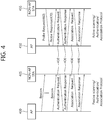
- Fig. 4 is a concept view illustrating an authentication and association process after scanning between an AP and an STA.
- the authentication and association may be conducted with one of the scanned APs.
- the authentication and association process may be carried out by way of, e.g., 2-way handshaking.
- a left part of Fig. 4 is a concept view illustrating an authentication and association process after passive scanning
- a right part of Fig. 4 is a concept view illustrating an authentication and association after active scanning.
- the authentication and association process may be equally performed by exchanging an authentication request frame 410/authentication response frame 420 and an association request frame 430/association response frame 440 between the AP 400 or 450 and the non-AP STA 405 or 455 regardless of which one of the active scanning method and the passive scanning method has been used.
- the authentication process may be conducted by transmitting the authentication request frame 410 from the non-AP STA 405 or 455 to the AP 400 or 450.
- the authentication response frame 420 may be transmitted from the AP 400 or 450 to the non-AP STA 405 or 455.
- the authentication frame format is set forth in IEEE 802.11 Ch. 8.3.3.11.
- the association process may be conducted by transmitting the association request frame 430 from the non-AP STA 405 or 455 to the AP 400 or 405.
- the association response frame 440 may be transmitted from the AP 400 or 450 to the non-AP STA 405 or 455.
- the transmitted association request frame 430 contains information on the capability of the non-AP STA 405 or 455. Based on the information on the capability of the non-AP STA 405 or 455, the AP 400 or 450 may determine whether the non-AP STA 405 or 455 may be supported.
- the AP 400 or 450 may include in the association response frame 440 whether to accept the association request frame 430 and a reason therefore, and its supportable capability information, and the AP 400 or 450 may send the same to the non-AP STA 405 or 455.
- the association frame format is set forth in IEEE 802.11 Chs. 8.3.3.5/8.3.3.6.
- association step After the association step is done, normal data transmission and reception is carried out.
- the association unless done, is re-conducted based on the reason for which the association is not performed, or association with other AP may be performed.
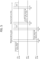
- Fig. 5 is a concept view illustrating an active scanning procedure.
- the active scanning procedure may be performed in the following steps.
- the STA 500 should perform monitoring to determine whether the parameter of PHY-CCA.indication is busy until the probe timer reaches the minimum channel time.
- the MLME may receive MLME-SCAN.request primitive.
- MLME-SCAN.request primitive is a primitive created by the SME.
- MLME-SCAN.request primitive may be used to determine whether there is other BSS to which the STA is to be connected.
- MLME-SCAN.request primitive may contain information specifically such as BSSType, BSSID, SSID, ScanType, ProbeDelay, ChannelList, MinChannelTime, MaxChannelTime, Requestlnformation, SSID List, ChannelUsage, AccessNetworkType, HESSID, MeshID, VendorSpecificInfo.
- the details of MLME-SCAN.request primitive are set forth in IEEE Draft P802.11-REVmbTM/D12, November 2011 'IEEE Standard for Information Technology Telecommunications and information exchange between systems-Local and metropolitan area networks-Specific requirements Part 11: Wireless LAN Medium Access Control (MAC) and Physical Layer (PHY) Specifications' 6.3.3.2 MLME-SCAN.request disclosed on November, 2011.
- Table 1 briefly represents example information included in MLME-SCAN.request primitive.
- name description BSSType Determines whether infrastructure BSS, IBSS, MBSS (Mesh basic service set), or all, are included in the scan BSSID Identifies a specific or wildcard BSSID SSID Specifies the desired SSID or the wildcard SSID ScanType Indicates either active or passive scanning ProbeDelay Delay(in microseconds) to be used prior to transmitting a probe frame during active scanning ChannelList Specifies a list of channels that are examined when scanning for a BSS MinChannelTime The minimum time(in TU) to spend on each channel when scanning MaxChannelTime The maximum tine(in TU) to spend on each channel when scanning RequirementInformation This element is optionally present if dot11RadioMeasurementActivated is true and is placed in a Probe Request frame to request that the responding STA include the requested information in the Probe Response frame SSID List One or more SSID elements that are
- the request parameter included in MLME-SCAN.request primitive may be used to determine whether the responding STA is to transmit a probe response frame.
- the request parameter may contain information for requesting that other BSS's information be included in the probe response frame.
- the request parameter may include a report request field, a delay reference field, and a maximum delay limit field.
- the report request field contains information to request that other BSS's information be included in the probe response frame
- the delay reference field contains information on the delay type applied as a response to the probe request frame
- the maximum delay limit field may contain the maximum access delay information on the delay type indicated by the delay reference field.
- the request parameter may include a minimum data rate field and/or a received signal strength limit field.
- the minimum data rate field contains information on the lowest overall data rate in transmitting an MSDU or A-MSDU.
- the received signal strength limit field may further contain information on the limit value of the signal necessary for a recipient of the probe request frame to respond.
- Fig. 6 is a concept view illustrating a probe request frame transmission method.
- Fig. 6 discloses methods of broadcasting, multicasting, and unicasting probe request frames from an STA.
- FIG. 6 shows a method in which the STA 600 broadcasts the probe request frame 610.
- the STA 600 may include a wildcard SSID and a wildcard BSSID in the probe request frame 610 and broadcast the probe request frame 610.
- the wildcard SSID and the wildcard BSSID may be used as identifiers to indicate all of the APs 605-1, 605-2, 605-3, 605-4, and 605-6 included in the transmission range of the STA 600.
- the APs 605-1, 605-2, 605-3, 605-4, and 605-6 that have received the probe request frame 610 from the STA 600 may send probe response frames to the STA 600 in response to the received probe request frame.
- the problem may occur that the STA 600 should simultaneously receive and process too many probe response frames.
- FIG. 6 An middle part of Fig. 6 shows a method in which the STA 620 unicasts the probe request frame 630.
- the STA 620 may transmit the probe request frame 630 containing particular SSID/BSSID information of the AP.
- the STA 620 may transmit a probe response frame to the STA 620.
- FIG. 6 shows a method in which the STA 640 multicasts the probe request frame 660.
- the STA 640 may include an SSID list and a wildcard BSSID in the probe request frame 660 and transmit the same.
- the APs 660-1 and 660-2 corresponding to the SSIDs included in the SSID list contained in the probe request frame may transmit a probe response frame to the STA 640.
- existing STAs transmits the probe request frame based on unicasttransmission after the probe delay time and waitsto receive ACK and the probe response frame transmitted by the AP.
- the existing STAs transmitting the probe request frame can monitors the current channel until the MaxChannelTime without scanning another channel when the existing STAs receives PHY-CCA.indication primitive even if the existing STAs cannot receives ACK after SIFS and the MinChannelTime has been expired.
- FIG. 7 is a concept diagram illustrating an active scanning method of a scanning STA.
- an STA 700 starts a method for perform active scanning.
- the STA 700 may receive a MLME-SCAN request primitive where a scanning time is indicated by active scan to perform a following operation with respect to each scanning target channel.
- the STA 700 waits until the probe delay time is expired and a PHY-RXSTART. indication primitive is received, and may perform access by a basic access procedure. When the access is possible, the STA 700 may transmit a probe request frame 730 to an AP 750. The AP 750 receiving the probe request frame may be indicated by a MLME-SCAN request primitive. The STA 700 sets a probe timer to 0 and starts a probe timer.
- the STA 700 may set the NAV to 0 to scan a next channel. Conversely, when the PHY-CCA. indication primitive (busy) is searched before the probe timer becomes the minimum channel time, the STA 700 may perform a following procedure.
- the STA 700 may process a received probe response frame 780. Further, the STA 700 may process a received beacon, a measurement pilot or a FILS search frame.
- the STA 700 may differently set timing to report a scanning result based on configuration with respect to a reporting method.
- the STA 700 may generate a MLME-SCAN. confirmation primitive including the searched result.
- the STA 700 may generate the MLME-SCAN. confirmation primitive based on all results of performing scanning a corresponding channel at a maximum channel time.
- FIG. 8 is a concept diagram illustrating an active scanning method according to an embodiment of the present invention.
- FIG. 8 discloses an active scanning operation for reducing scanning delay of the STA.
- the STA may determine whether to perform the active scanning operation based on presence of reception of an acknowledgement (ACK).
- ACK acknowledgement
- the STA When the STA transmits the probe request frame and searches a PHY-CCA. Indication primitive (busy) in order to reduce the scanning delay, if the ACK is not received after an SIFS, the STA may move to a channel different from a current channel. When scanning all the channels is terminated, the scanning procedure may be terminated.
- the embodiment of the present invention is described on the assumption that a scanning channel is moved to another channel from the current channel.
- the STA may determine that a target AP is not located around the STA and may not monitor a current channel until a maximum channel time, and move the scanning channel to another channel to perform scanning the move channel. In practice, if it is assumed that the target AP is not located, the STA may reduce the scanning delay by a difference (maximum channel time - minimum channel time) between the maximum channel time and the minimum channel time.
- FIG. 8 illustrates that the STA monitors presence of transmission of the ACK and determines whether to move the scanning channel.
- the STA may perform monitoring for a time shorter than the minimum channel time with respect to the presence of transmission of the ACK.
- FIG. 9 illustrates a method of monitoring whether to transmit the ACK for a short inter frame space (SIFS) after transmission of the probe request frame being a time short than the minimum channel time.
- SIFS short inter frame space
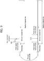
- FIG. 9 is a concept diagram illustrating an active scanning method according to an embodiment of the present invention.
- FIG. 9 illustrates a method of monitoring whether to transmit an ACK for a time shorter than a minimum channel time by an STA.
- the STA may move the scanning channel to a next channel.
- the STA may reduce scanning delay by a difference (maximum channel time - SIFS) between the maximum channel time and the SIFS.
- an embodiment of the present invention discloses a method of monitoring a channel when the STA performs active scanning.
- An existing STA transmits a probe request frame after probe delay and monitors a probe response frame transmitted from the AP.
- the AP transmits a probe response frame but the STA may not receive a probe response frame due to collision or other problems.
- the STA searches a PHY-CCA. Indication primitive (busy)
- the STA does not receive the probe response frame at a corresponding channel and may perform a scanning procedure by changing the scanning channel to other channel after the maximum channel time.
- the AP does not receive the ACK with respect to a first probe response frame transmitted to the STA from the STA. Accordingly, the AP may retransmit the probe response frame to the STA. If the probe response frame retransmitted from the AP is transmitted after the minimum channel time, since the STA previously moves to another channel, the STA may not receive the probe response frame.
- the STA may transmit a probe request frame while adding information on a method of monitoring a channel to the probe request frame.
- the AP may determine a method of transmitting a probe response frame based on information on a method of monitoring a channel transmitted from the STA.
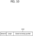
- FIG. 10 is a concept diagram illustrating a probe request frame according to an embodiment of the present invention.
- FIG. 10 discloses a method of transmitting a probe request frame in such a way that the STA adds information on a method of monitoring a channel to the probe request frame.
- the probe request frame may include a channel monitoring type field 1000.
- the channel monitoring type field 1000 may include information on a method of monitoring a channel when the STA transmits the probe response frame.
- the STA searches a PHY-CCA. indication primitive (busy) for the minimum channel time but the STA does not receive a PHY-RXSTART. Indication primitive, the STA does not monitor a probe response frame by the maximum channel time and may indicate to move to a next scanning channel after the minimum channel time.
- the STA searches a PHY-CCA. Indication primitive for a minimum channel time. PHY-RXSTART but the STA does not receive a PHY-RXSTART. indication primitive, the STA may indicate to monitor a probe response frame by the maximum channel time.
- the above channel monitoring type is one example of a used field in order to indicate a channel monitoring method of the STA, and may indicate information on a channel monitoring type of the STA using various other fields and field values.
- the STA may determine a channel monitoring type based on available scanning delay.
- the available scanning delay may include information on an available time in order to receive the probe response frame in the scanning channel by the STA.
- the STA may determine a channel monitoring type according to presence of sensitivity to the scanning delay.
- FIG. 11 is a concept diagram illustrating an active scanning method of an STA according to an embodiment of the present invention.
- FIG. 11 discloses an active scanning method of the STA when the channel monitoring type field disclosed in FIG. 10 is set to 1.
- the STA may determine a value of a channel monitoring type field according to various determinations. For example, when reception of the probe response frame is a factor more important than reduction of the scanning delay, the STA may transmit the probe request frame having a value of the channel monitoring type field set to 1 to the AP.
- the STA transmits a probe request frame having a value of a channel monitoring type field set to 1.
- the STA searches a PHY-CCA. indication primitive for the minimum channel time but the STA does not receive the PHY-RXSTART. indication primitive, the STA may indicate to monitor the probe response frame by the maximum channel time.
- the AP transmits the probe response frame, but the STA does not receive the probe response frame due to a problem such as collision and searches PHY-CCA. indication primitive (busy), and does not receive the PHY-RXSTART. indication primitive.
- the STA may monitor a current channel until the maximum channel time.
- the AP may know that the STA monitors a current channel until the maximum channel time. Since the AP does not receive an ACK with respect to the probe response frame transmitted from the STA, the AP may retransmit the probe response frame to the STA. The AP may determine retransmission of the probe response frame based on the information on the channel monitoring type field.
- the AP may determine whether to retransmit the probe request frame based on the information on the channel monitoring type field included in the probe request frame. Only when the value of the channel monitoring type field included in the probe request frame transmitted from the STA is 1, the AP may retransmit the probe response frame. Conversely, the value of the channel monitoring type time included in the probe request frame transmitted from the STA is 0, the AP determines that the STA moves to another channel and may not retransmit the probe response frame.
- An operation of determining whether to transmit the probe response frame of the AP is one example and the AP may perform another operation according to the channel monitoring type field. For example, when the channel monitoring type field is 1, retransmission of the probe response frame of the AP may not be limited until the maximum channel time is terminated. Conversely, when the channel monitoring type field is 0, retransmission of the probe response frame may be restrictively performed until the minimum channel time is terminated.
- the STA may monitor until the maximum channel time to receive a probe response frame previously transmitted from the AP.
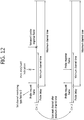
- FIG. 12 is a concept diagram illustrating an active scanning method of an STA according to an embodiment of the present invention.
- FIG. 12 discloses an active scanning method of the STA when a channel monitoring type field illustrated in FIG. 10 is set to 0.
- the STA may determine a value of the channel monitoring type field according to various determinations. For example, when the reduction of the scanning delay is a factor more important than the reception of the probe response frame, the STA may transmit the probe request frame having a value of the channel monitoring type field set to 0 to the AP.
- the STA transmits a probe request frame having a channel monitoring type field set to 0.
- the STA searches a PHY-CCA. indication primitive for the minimum channel time but the STA does not receive the PHY-RXSTART. indication primitive, the STA may indicate to monitor the probe response frame by the minimum channel time.
- the AP transmits the probe response frame, but the STA does not receive the probe response frame due to a problem such as collision and searches PHY-CCA. indication primitive (busy), and does not receive the PHY-RXSTART. indication primitive.
- the STA may monitor the current channel until the minimum channel time. Since the AP does not receive an ACK with respect to the probe response frame transmitted from the STA, the AP may retransmit the probe response frame to the STA. The AP may determine retransmission of the probe response frame based on the information on the channel monitoring type field.
- the AP determines that the STA moves to another channel and may not perform retransmission of the probe response frame.
- the AP may restrictively perform retransmission of the probe response frame for the minimum channel time unit the STA moves to another channel.
- the STA may transmit a method of monitoring a channel to the AP when the STA performs active scanning based on various information formats.
- a FILS indication element and an active scanning delay sensitive type element may be included in the probe request frame.
- the STA searches a PHY-CCA. indication primitive (busy) based on the FILS indication element and the active scanning delay sensitive type element but does not receive the PHY-RXSTART. indication primitive, the STA may indicate to move to a next scanning channel after a minimum channel time. Further, in the same manner, when the STA searches a PHY-CCA. indication primitive (busy) based on the FILS indication element and the active scanning delay sensitive type element but does not receive the PHY-RXSTART. indication primitive, the STA may monitor a probe response frame until a maximum channel time.
- the FILS indication element may indicate information on whether or not the STA is a fast initial link setup (FILS) STA.
- the STA is divided whether or the STA is a FILS STA. Only when the STA is the FILS STA, the STA may additionally determine a method of monitoring a channel upon performing the active scanning. For example, when the element ID is 0, the STA is the non-FILS STA. When the element ID is 1, the STA is a FILS STA.
- the active scanning delay sensitive type element may be used to transfer information on a method of performing active scanning by the FILS STA.
- the scanning time may be differently set. For example, it may be assumed that the FILS indication element is set to 1 and the active scanning delay sensitive type element is set to 1. In this case, when the STA searches PHY-CCA. Indication primitive (busy) for the minimum channel time, but does not receive the PHY-RXSTART. indication primitive, the STA may move to a next channel after the minimum channel time to perform scanning.
- the STA searches the PHY-CCA. indication primitive (busy) for the minimum channel time.
- the STA may extend a probe timer of the STA to monitor a probe response frame until the maximum channel time.
- the information on the channel monitoring type of the STA may be transmitted based on various information formats.
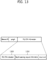
- FIG. 13 and FIG. 14 illustrate examples of other information format to transmit information on the channel monitoring type of the STA.
- FIG. 13 is a concept diagram illustrating an information format to transmit information on active scanning of the STA according to an embodiment of the present invention.
- FIG. 13 illustrates an information formation for transmitting information on an operation upon active scanning.
- the above information may be transmitted while being included in the probe request frame of the STA as described above.
- An FILS STA information element defined as a specific element ID in the probe request frame may be transmitted.
- the FILS STA information element may include the FILS STA indication 1300 and rapid scanning request information 1350.
- the FILS STA indication 1300 may include information for indicating whether or not a current STA is the FILS STA. For example, when the FILS STA indication 1300 is 1, it may be indicated that the STA is the FILS STA.
- the rapid scanning request information 1350 may be further included when the STA is the FILS STAT based on the FILS STA indication 1300.
- the rapid scanning request information 1350 may include information on whether to move the scanning channel to another channel when the STA does not receive the PHY-RXSTRAT. indication primitive before the probe time become the minimum channel time.
- the STA may move the scanning channel to another channel after the minimum channel time. That is, the STA may set an NAV to the 0 to scan a next channel.
- the STA may monitor a frame from a corresponding channel until the maximum channel time.
- FIG. 14 is a concept diagram illustrating an information format to transmit information on active scanning of the STA according to an embodiment of the present invention.
- FIG. 14 illustrates an information format for transmitting information on an operation upon active scanning.
- the above information may be transmitted while being included in the probe request frame of the STA.
- the above information may not include information on whether the STA is the FILS STA.
- Rapid scanning request information 1400 may be included in the probe request frame.
- the rapid scanning request information 1400 may include information on whether to move the scanning channel to another channel when the FILS STA does not receive a PHY-RXSTART. indication primitive before the probe time becomes the minimum channel time.
- the FILS STA may move the scanning channel to another channel after the minimum channel time. That is, the FILS STA may set the NAV to 0 to scan a next channel.
- the FILS STA may monitor the frame from a corresponding channel until the maximum channel time.
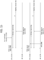
- FIG. 15 is a concept diagram illustrating an active scanning method of a scanning STA according to an embodiment of the present invention.
- FIG. 15 discloses a method of performing active scanning by the STA.
- the STA may receive a MLME-SCAN. request primitive where the scanning type is indicated by active scan to perform a following operation with respect to each scanning target channel.
- the STA may perform access according to a basic access procedure. When the access is possible, the STA may transmit the probe request frame to the AP. An AP to which the STA transmits the probe request frame may be indicated by an MLME-SCAN. request primitive. The STA sets a timer to 0 and starts the probe timer.
- the STA may set the NAV to 0 to scan a next channel.
- the PHY-CCA.indication primitive busy
- the STA 1510 searches a PHY-CCA. indication primitive after transmission of the probe request frame 1505, and may differently perform a channel scanning procedure according to whether to receive the PHY-RXSTART. indication primitive 1500.
- the STA 1510 may perform a following operation according to the channel monitoring type field configured by the STA 1510. For example, when the PHY-RXSTART. indication primitive 1500 is received, the STA 1510 may monitor the channel until the maximum channel time to receive the probe response frame 1525. When the PHY-RXSTART. indication primitive 1500 is not received, the STA 1510 may move the scanning channel to another channel after the minimum channel time.
- the STA 1560 may determine a method of scanning the channel according to whether to receive an ACK 1550 with respect to the probe request frame 1565. For example, when the STA 1560 receives the ACK 1550 with respect to the probe request frame 1565 transmitted from the STA 1560, the STA 1560 may monitor the channel until the maximum channel time. Conversely, when the STA 1560 does not receive the ACK 1550 with respect to the probe request frame 1565 transmitted from the STA 1560, the STA 1560 may monitor the channel until the minimum channel time to move the scanning channel to another channel after the minimum channel time.
- FIG. 16 is a block diagram illustrating a wireless device according to an embodiment of the present invention.
- a wireless device 1600 is an STA capable of implementing the above embodiment and may be an AP or a non-AP STA.
- the wireless device 1600 includes a processor 1620, a memory 1640, and a radio frequency (RF) unit 1660.
- the RF unit 1660 is connected to the processor 1620, and sends and receives radio signals.
- the processor 1620 performs the proposed functions, processes and/or methods.
- the processor 1620 may be configured to implement an operation the wireless device 1600 according to the embodiment of the present invention.
- the processor 1620 may transmit a probe request frame including channel monitoring type information in a scanning channel to the AP, may determine whether the scanning channel is in a busy state until the minimum channel time, and may determine whether to receive a PPDU including a valid PLCP header at the scanning channel by the minimum channel time.
- the processor 1620 may be configured to determine a time of monitoring the probe response frame transmitted from the AP at a scanning channel based on whether the PPDU is received by the minimum channel time and channel monitoring type information.
- the processor 1620 may include Application-Specific Integrated Circuits (ASICs), other chipsets, logic circuits, data processors, and/or a converter for converting a baseband signal and a wireless signal.
- the memory 1640 may include Read-Only Memory (ROM), Random Access Memory (RAM), flash memory, memory cards, storage media and/or other storage devices.
- the RF unit 1660 may include at least one antenna configured to send and receive radio signals.
- the processor 1620 may include an ASIC (Application-Specific Integrated Circuit), other chipset, a logic circuit, a data processing device, and/or a converter that performs conversion between a baseband signal and a radio signal.
- the memory 1640 may include a ROM (Read-Only Memory), a RAM (Random Access Memory), a flash memory, a memory card, a storage medium, and/or other storage device.
- the RF unit 1660 may include one or more antennas that transmit and/or receive radio signals.
- the above-described schemes may be embodied in modules (processes, or functions, etc.) performing the above-described functions.
- the modules may be stored in the memory 1640 and may be executed by the processor 1620.
- the memory 1640 may be positioned in or outside the processor 1620 and may be connected with the processor 1620 via various well-known means.
Landscapes
- Engineering & Computer Science (AREA)
- Computer Networks & Wireless Communication (AREA)
- Signal Processing (AREA)
- Computer Security & Cryptography (AREA)
- Mobile Radio Communication Systems (AREA)
Description
- The present invention relates to a wireless local area network (LAN) and, more particularly, to a method and a device for performing active scanning.
- In recent years, a wireless LAN technology has been chiefly evolved to three directions. There are institute of electrical and electronic engineers (IEEE) 802.11ac and IEEE 802.11ad as efforts for further increasing a transmission rate as an extension of an evolving direction of a wireless LAN according to the related art. The IEEE 802.11ad is a wireless LAN technology using a 60GHz band. In addition, in order to enable wide band transmission in a distance side as compared with a wireless LAN according to the related art, a wide band wireless LAN using a frequency band less than 1GHz has been recently spotlighted. Accordingly, there are an IEEE 802.11af using a TV white space (TVWS) and an IEEE 802.11ah using a 900MHz band. The IEEE 802.11af and the IEEE 802.11ah is mainly aimed at extending in a Wi-Fi (extended range Wi-Fi) service as well as a smart grid and a wide band sensor network. Further, an existing wireless LAN medium access control (MAC) has a problem that an initial link setup time is long in some cases. When the station (STA) performs rapid access to an AP, IEEE 802.11ai standardization activity has been actively achieved.
- The IEEE 802.11ai is a MAC technology to achieve a rapid authentication process in order to significantly reduce initial set-up and an association time of the wireless LAN and starts standardization activity as a normal task group in January 2011. In order to enable a rapid access process, the IEEE 802.11ai has discussed about simplification of a process in AP discovery, network discovery, time synchronization function (TSF) synchronization, authentication & association, and a procedure combination with a higher layer. Among them, ideas such as procedure combination using a piggyback of a dynamic host configuration protocol (DHCP), optimization of full extensible authentication protocol (EAP) using a concurrent IP, and an efficient selective access point (AP) scanning are discussed.
- In LIN CAI: "ProbeTimer of Active Scanning", IEEE-SA Mentor, vol.802.11ai, no.1 of July 18, 2012 following ProbeTimer settings for time reduction in CCA busy primitives are suggested: 1) When CCA busy primitive is not detected, the ProbeTimer is MinChannelTime; 2) When CCA busy primitive is detected and STAs receive some implicit or explicit messages with evidence of APs' existence, the ProbeTimer is MaxChannelTime; 3) When CCA busy primitive is detected, but there is no hard evidence of APs' presence, the ProbeTimer is MedChannelTime. To reduce unnecessary scanning delay, STAs should be able to decide its ProbeTimer based on the detection of an identifiable AP transmissions rather than CCA only.
- PHILLIP BARBER: "Active Scanning Time Notification", IEEE-SA Mentor, vol.802.11ai of January 12, 2012 proposes a method to let the AP know exactly how much time is scheduled by the STA to wait for AP's probe response to save AP's trouble of retrying sending probe response. Therein, the AP gets the exact Probe Response Wait Time of STA by receiving the STA's probe request which includes a unique IE and when the AP has not successfully sent out the probe response during the Probe Response Wait Time, then the AP could stop trying to send the probe response to STA.
- The above identified objects are solved by the independent claims. Advantageous embodiments can be derived from the dependent claims. The present invention provides a method for performing active scanning of a STA.
- The present invention further provides an STA for performing active scanning.
- Embodiments not covered by the claims are to be considered merely as examples.
- Preferably, a method for active scanning of a station (STA) includes: transmitting, by the STA, to an access point (AP), a probe request frame including channel monitoring type information in a scanning channel; determining, by the STA, whether the scanning channel is in a busy state until a MinimumChannelTime; determining, by the STA, whethera physical layer convergence procedure protocol data unit (PPDU) including a valid physical layer convergence procedure (PLCP) header is received in the scanning channel until the MinimumChannelTime; and determining a time for monitoring a probe response frame transmitted by the AP in the scanning channel based on whether the PPDU is received until the MinimumChannelTime and the channel monitoring type information, when the scanning channel is in the busy state, wherein the channel monitoring type information includes information related to a type of the STA to monitor the probe response frame in the scanning channel. The time for monitoring the probe response frame is determined as the MinimumChannelTime when the PPDU is not received in the scanning channel until the MinimumChannelTime and the channel monitoring type information indicates a first type, and the time for monitoring the probe response frame may be determined as a MaxChannelTime when the PPDU is not received in the scanning channel until the MinimumChannelTime and the channel monitoring type information indicates a second type. The method may further include monitoring, by the STA, the scanning channel during the maximum channel time when the STA receives the PPDU in the scanning channel until the MinimumChannelTime. The probe request frame may further include information related to whether the STA is an STA for performing rapid link configuration, and wherein the time for monitoring the probe response frame may be determined when the STA is a STA for performing rapid link configuration. The AP may determine whether to retransmit the probe response frame based on the channel monitoring type information
- Preferably, a STA for active scanning includes: A station (STA) for performing active scanning, the STA including: a radio frequency (RF) unit configured to transmits and receive radio signals; and a processor operatively coupled to the RF unit and configured to: transmit
to an access point (AP), a probe request frame including channel monitoring type infor- to an access point (AP), a probe request frame including channel monitoring type information in a scanning channel; determine whether the scanning channel is in a busy state until MinimumChannelTime, determine whethera PPDU including a valid physical layer convergence procedure (PLCP) header is received in the scanning channel until the MinimumChannelTime, and determinea time for monitoring a probe response frame transmitted by the AP in the scanning channel based on whether the PPDU is received until the MinimumChannelTime and the channel monitoring type information, when the scanning channel is in the busy state, wherein the channel monitoring type information includes information related to a type of the STA to monitor the probe response frame in the scanning channel. The time for monitoring the probe response frame may be determined as the MinimumChannelTime when the PPDU is not received in the scanning channel until the MinimumChannelTime and the channel monitoring type information indicates a first type, and the time for monitoring the probe response frame may be determined as a MaxChannelTime when the PPDU is not received in the scanning channel until the MinimumChannelTime and the channel monitoring type information indicates a second type. The processor may be configured to monitor the scanning channel during the maximum channel time when the PPDU is received in the scanning channel until the
MinimumChannelTime. The probe request frame further includes information related to whether the STA is an STA for performing rapid link configuration, and the time for monitoring the probe response frame may be determined when the STA is an STA for performing rapid link configuration. The AP may determine whether to retransmit the probe response frame based on the channel monitoring type information. The processor may be configured to determine the channel monitoring type information based on available scanning delay, and the available scanning delay may be an available time in order to receive the probe response frame in the scanning channel by the STA. - The STA may determine a time for monitoring a scanning channel for active channel by determining whether the AP is located in a channel. By using the above method, when the AP is not located in a scanning channel, the STA may rapidly search the AP by reducing a time for scanning the scanning channel.
-
-
FIG. 1 is a concept diagram illustrating a configuration of a wireless local area network (WLAN). -
FIG. 2 is a diagram illustrating a layer architecture of a WLAN system supported by IEEE 802.11. -
FIG. 3 is a concept diagram illustrating a scanning method in the WLAN. -
FIG. 4 is a concept diagram illustrating an authentication and association procedure after scanning of an AP and a STA. -
FIG. 5 is a concept diagram illustrating an active scanning procedure. -
FIG. 6 is a concept diagram illustrating a method for transmitting a probe request frame. -
FIG. 7 is a concept diagram illustrating an active scanning method of a scanning STA. -
FIG. 8 is a concept diagram illustrating an active scanning method according to an embodiment of the present invention. -
FIG. 9 is a concept diagram illustrating an active scanning method according to an embodiment of the present invention. -
FIG. 10 is a concept diagram illustrating a probe request frame according to an embodiment of the present invention. -
FIG. 11 is a concept diagram illustrating an active scanning method of an STA according to an embodiment of the present invention. -
FIG. 12 is a concept diagram illustrating an active scanning method of an STA according to an embodiment of the present invention. -
FIG. 13 is a concept diagram illustrating an information format to transmit information on active scanning of the STA according to an embodiment of the present invention. -
FIG. 14 is a concept diagram illustrating an information format to transmit information on active scanning of the STA according to an embodiment of the present invention. -
FIG. 15 is a concept diagram illustrating an active scanning method of a scanning STA according to an embodiment of the present invention. -
FIG. 16 is a block diagram illustrating a wireless device according to an embodiment of the present invention. -
Fig. 1 is a concept view illustrating the structure of a wireless local area network (WLAN). - An upper part of
Fig. 1(A) shows the structure of the IEEE (institute of electrical and electronic engineers) 802.11 infrastructure network. - Referring to the upper part of
Fig. 1(A) , the WLAN system may include one or more basic service sets (BSSs, 100 and 105). TheBSS - The infrastructure BSS may include at least one STA,
APs - The
distribution system 110 may implement an extended service set (ESS) 140 by connecting a number ofBSSs more APs distribution system 110. The APs included in oneESS 140 may have the same SSID (service set identification). - The portal 120 may function as a bridge that performs connection of the WLAN network (IEEE 802.11) with other network (for example, 802.X).
- In the infrastructure network as shown in the upper part of
Fig. 1 , a network between theAPs APs APs APs - A lower part of
Fig. 1 is a concept view illustrating an independent BSS. - Referring to the lower part of
Fig. 1 , the independent BSS (IBSS) is a BSS operating in ad-hoc mode. The IBSS does not include an AP, so that it lacks a centralized management entity. In other words, in the IBSS, the STAs 150-1, 150-2, 150-3, 155-4 and 155-5 are managed in a distributed manner. In the IBSS, all of the STAs 150-1, 150-2, 150-3, 155-4 and 155-5 may be mobile STAs, and access to the distribution system is not allowed so that the IBSS forms a self-contained network. - The STA is some functional medium that includes a medium access control (MAC) following the IEEE (Institute of Electrical and Electronics Engineers) 802.11 standards and that includes a physical layer interface for radio media, and the term "STA" may, in its definition, include both an AP and a non-AP STA (station).
- The STA may be referred to by various terms such as mobile terminal, wireless device, wireless transmit/receive unit (WTRU), user equipment (UE), mobile station (MS), mobile subscriber unit, or simply referred to as a user.
-
Fig. 2 is a view illustrating a layer architecture of a WLAN system supported by IEEE 802.11. -
Fig. 2 conceptually illustrates a layer architecture (PHY architecture) of a WLAN system. - The WLAN system layer architecture may include an MAC (medium access control)
sub-layer 220, a PLCP (Physical Layer Convergence Procedure)sub-layer 210, and a PMD (Physical Medium Dependent)sub-layer 200. ThePLCP sub-layer 210 is implemented so that theMAC sub-layer 220 is operated with the minimum dependency upon thePMD sub-layer 200. ThePMD sub-layer 200 may serve as a transmission interface to communicate data between a plurality of STAs. - The
MAC sub-layer 220, thePLCP sub-layer 210, and thePMD sub-layer 200 may conceptually include management entities. - The management entity of the
MAC sub-layer 220 is denoted an MLME (MAC layer management entity, 225), and the management entity of the physical layer is denoted a PLME (PHY layer management entity, 215). Such management entities may offer an interface where a layer management operation is conducted. ThePLME 215 is connected with theMLME 225 to be able to perform a management operation on thePLCP sub-layer 210 and thePMD sub-layer 200, and theMLME 225 is also connected with thePLME 215 to be able to perform a management operation on theMAC sub-layer 220. - There may be an SME (STA management entity, 250) to perform a proper MAC layer operation. The
SME 250 may be operated as a layer independent component. The MLME, PLME, and SME may communicate information between the mutual components based on primitive. - The operation of each sub-layer is briefly described below. The
PLCP sub-layer 210 delivers an MPDU (MAC protocol data unit) received from theMAC sub-layer 220 according to an instruction from the MAC layer between theMAC sub-layer 220 and thePMD sub-layer 200 to thePMD sub-layer 200 or delivers a frame from thePMD sub-layer 200 to theMAC sub-layer 220. ThePMD sub-layer 200 is a PLCP sub-layer and thePMD sub-layer 200 may communicate data between a plurality of STAs by way of a radio medium. The MPDU (MAC protocol data unit) delivered from theMAC sub-layer 220 is denoted a PSDU (Physical Service Data Unit) on the side of thePLCP sub-layer 210. The MPDU is similar to the PSDU, but in case an A-MPDU (aggregated MPDU), which is obtained by aggregating a plurality of MPDUs, has been delivered, each MPDUs may differ from the PSDU. - The
PLCP sub-layer 210 adds an additional field including information required by the physical layer transceiver while receiving the PSDU from theMAC sub-layer 220 and delivering the same to thePMD sub-layer 200. In this case, the added field may include a PLCP preamble to the PSDU, a PLCP header, and tail bits necessary to return the convolution encoder to zero state. The PLCP preamble may play a role to allow the receiver to prepare for syncing and antenna diversity before the PSDU is transmitted. The data field may include padding bits to the PSDU, a service field including a bit sequence to initialize the scrambler, and a coded sequence in which a bit sequence added with tail bits has been encoded. In this case, as the encoding scheme, one of BCC (Binary Convolutional Coding) encoding or LDPC (Low Density Parity Check) encoding may be selected depending on the encoding scheme supported by the STA receiving the PPDU. The PLCP header may include a field containing information on the PPDU (PLCP Protocol Data Unit) to be transmitted. - The
PLCP sub-layer 210 adds the above-described fields to the PSDU to generate the PPDU (PLCP Protocol Data Unit) and transmits the same to a receiving station via thePMD sub-layer 200, and the receiving station receives the PPDU and obtains information necessary for data restoration from the PLCP preamble and PLCP header to thus restore the same. -
Fig. 3 is a concept view illustrating a scanning method in a WLAN. - Referring to
Fig. 3 , the scanning method may be divided intopassive scanning 300 andactive scanning 350. - Referring to a left part of
Fig. 3 , thepassive scanning 300 may be performed by abeacon frame 330 that is periodically broadcast from theAP 310. TheAP 310 in the WLAN broadcasts thebeacon frame 330 to thenon-AP STA 340 at a particular period (e.g., per 100msec). Thebeacon frame 330 may contain information on the current network. Thenon-AP STA 340 may perform scanning on the channel with theAP 310 to perform the authentication/association process by obtaining the network information from thebeacon frame 330 periodically broadcast. - The
passive scanning method 300 only receives thebeacon frame 330 transmitted from theAP 310 without the need for thenon-AP STA 340 to transmit a frame. Accordingly, thepassive scanning 300 is advantageous of a reduction in the overall overhead that is created upon data transmission/reception over the network. However, since the scanning is obliged to be passively performed in proportion to the period of thebeacon frame 330, the time taken to perform scanning may be increased. The details of the beacon frame are set forth in IEEE Draft P802.11-REVmb™/D12, November 2011 'IEEE Standard for Information Technology Telecommunications and information exchange between systems-Local and metropolitan area networks-Specific requirements Part 11: Wireless LAN Medium Access Control (MAC) and Physical Layer (PHY) Specifications(hereinafter, IEEE 802.11)' 8.3.3.2 beacon frame disclosed on November, 2011. IEEE 802.11ai may additionally use other format of a beacon frame, and such beacon frame may be referred to as a FILS (fast initial link setup) beacon frame. Further, the measurement pilot frame is a frame containing only some information of the beacon frame, and the measurement pilot frame may be used in the scanning procedure. The measurement pilot frame is set forth in IEEE 802.11 8.5.8.3 measurement pilot format. - Referring to a right part of
Fig. 3 , theactive scanning 350 refers to a method in which thenon-AP STA 390 leads scanning by transmitting aprobe request frame 370 to theAP 360. - After receiving the
probe request frame 370 from thenon-AP STA 390, theAP 360 may wait a random time to prevent frame collision, and theAP 360 then includes network information in aframe response frame 380, then sending the same to thenon-AP STA 390. Thenon-AP STA 390 may obtain the network information based on the receivedprobe response frame 380 to stop the scanning process. - The
active scanning 350 allows thenon-AP STA 390 to lead the scanning process, and theactive scanning 350 has the advantage of a short scanning time. However, thenon-AP STA 390 should transmit the probe request frame 37, resulting in an increase in the network overhead for frame transmission and reception. Theprobe request frame 370 is set forth in IEEE 802.11 Ch. 8.3.3.9, and theprobe response frame 380 is set forth in IEEE 802.11 Ch. 8.3.3.10. - After the scanning is done, the AP and the STA may conduct an authentication and association procedure.
-
Fig. 4 is a concept view illustrating an authentication and association process after scanning between an AP and an STA. - Referring to
Fig. 4 , after passive/active scanning, the authentication and association may be conducted with one of the scanned APs. - The authentication and association process may be carried out by way of, e.g., 2-way handshaking. A left part of
Fig. 4 is a concept view illustrating an authentication and association process after passive scanning, and a right part ofFig. 4 is a concept view illustrating an authentication and association after active scanning. - The authentication and association process may be equally performed by exchanging an
authentication request frame 410/authentication response frame 420 and anassociation request frame 430/association response frame 440 between theAP non-AP STA - The authentication process may be conducted by transmitting the
authentication request frame 410 from thenon-AP STA AP authentication request frame 410, theauthentication response frame 420 may be transmitted from theAP non-AP STA - The association process may be conducted by transmitting the
association request frame 430 from thenon-AP STA AP association request frame 430, theassociation response frame 440 may be transmitted from theAP non-AP STA association request frame 430 contains information on the capability of thenon-AP STA non-AP STA AP non-AP STA AP association response frame 440 whether to accept theassociation request frame 430 and a reason therefore, and its supportable capability information, and theAP non-AP STA - After the association step is done, normal data transmission and reception is carried out. The association, unless done, is re-conducted based on the reason for which the association is not performed, or association with other AP may be performed.
-
Fig. 5 is a concept view illustrating an active scanning procedure. - Referring to
Fig. 5 , the active scanning procedure may be performed in the following steps. - (1) It is determined whether the
STA 500 is ready to perform the scanning procedure.
TheSTA 500 may wait, e.g., until the probe delay time expires or particular signaling information (for example, PHY-RXSTART.indication primitive) is received to perform active scanning.
The probe delay time is a delay that occurs before theSTA 500 sends aprobe request frame 510 when performing active scanning. PHY-RXSTART.indication primitive is a signal that is transmitted from the physical (PHY) layer to the local MAC (medium access control) layer. PHY-RXSTART.indication primitive may signal information indicating that the PLCP (physical layer convergence protocol) has received a PPDU (PLCP protocol data unit) including a valid PLCP header to the MAC layer. - (2) Basic access is performed.
In the 802.11 MAC layer, a number of STAs may share a radio medium using a distributed coordination function (DCF) that is a contention-based function. The DCF may prevent collision between STAs through a back-off scheme using the carrier sense multiple access/collision avoidance (CSMA/CA) as its access protocol. TheSTA 500 may transmit theprobe request frame 510 to theAPs 560 and 570 using a basic access method. - (3) Information for specifying the
APs 560 and 570 included in MLME-SCAN.request primitive (for example, SSID (service set identification) and BSSID (basic service set identification) information) may be included in theprobe request frame 510 and may be transmitted.
The BSSID may have a value corresponding to the MAC address of the AP as an indicator to specify the AP. The SSID (service set identification) is a network term for specifying an AP, which may be read by a person who operates the STA. The BSSID and/or SSID may be used to specify an AP.
TheSTA 500 may specify an AP based on the information to specify theAPs 560 and 570 included by MLME-SCAN.request primitive. The specifiedAPs 560 and 570 may send the probe response frames 540 and 550 to theSTA 500. TheSTA 500 may include the SSID and BSSID information in theprobe request frame 510 and send the same, thereby unicasting, multicasting, or broadcasting theprobe request frame 510. A method of unicasting, multicasting, or broadcasting theprobe request frame 510 using the SSID and BSSID information is further described with reference toFig. 5 .
For example, in case an SSID list is included in MLME-SCAN.request primitive, theSTA 500 may include the SSID list in theprobe request frame 510 and transmit the same. TheAPs 560 and 570 may receive theprobe request frame 510, determine the SSIDs included in the SSID list contained in the receivedprobe request frame 510, and determine whether to send the probe response frames 540 and 550 to theSTA 500. - (4) A probe timer is initialized as 0 and is then operated.
The probe timer may be used to check a minimum channel time (MinChanneltime, 520) and a maximum channel time (MaxChanneltime, 530). Theminimum channel time 520 and themaximum channel time 530 may be used to control the active scanning operation of theSTA 500.
Theminimum channel time 520 may be used to perform the operation for varying the channel for conducting active scanning. For example, in case theSTA 500 fails to receive the probe response frames 540 and 550 until theminimum channel time 520, theSTA 500 shifts scanning channels to perform scanning on other channel. In case theSTA 500 receives theprobe response frame 550 until theminimum channel time 520, it may process the received probe response frames 540 and 550 after waiting until themaximum channel time 530.
TheSTA 500 may detect PHY-CCA.indication primitive until the probe timer reaches theminimum channel time 520 and may determine whether other frame (for example, probe response frames 540 and 550) has been received by theSTA 500 until before theminimum channel time 520.
PHY-CCA.indication primitive may transmit information on the state of the medium from the physical layer to the MAC layer. PHY-CCA.indication primitive may indicate the current state of the channel using channel state parameters such as "busy" when the channel is unavailable and "idle" when the channel is available. TheSTA 500 may determine that there are probe response frames 540 and 550 received by theSTA 500 when PHY-CCA.indication is detected to be busy and may determine that there are no probe response frames 540 and 550 received by theSTA 500 when PHY-CCA.indication is detected to be idle.
In case PHY-CCA.indication is detected to be idle, theSTA 500 may set an NAV (net allocation vector) to 0, and theSTA 500 may scan a next channel. In case PHY-CCA.indication is detected to be busy, theSTA 500 may perform a process on the received probe response frames 540 and 550 after the probe timer reaches themaximum channel time 530. After the process on the received probe response frames 540 and 550 is done, theSTA 500 may set the NAV (net allocation vector) to 0 and may then scan a next channel.
Hereinafter, in embodiments of the present invention, determining whether there are probe response frames 540 and 550 received by theSTA 500 may also mean that the channel state is determined using PHY-CCA.indication primitive. - (5) In case all the channels included in the channel list (ChannelList) are scanned, the MLME may signal MLME-SCAN.confirm primitive. MLME-SCAN.confirm primitive may contain BSSDescriptionSet including all the information obtained in the scanning process.
- In case the
STA 500 uses the active scanning method, theSTA 500 should perform monitoring to determine whether the parameter of PHY-CCA.indication is busy until the probe timer reaches the minimum channel time. - The specific information included in the above-described MLME-SCAN is as follows. In order for the STA to perform scanning, the MLME may receive MLME-SCAN.request primitive. MLME-SCAN.request primitive is a primitive created by the SME. MLME-SCAN.request primitive may be used to determine whether there is other BSS to which the STA is to be connected.
- MLME-SCAN.request primitive may contain information specifically such as BSSType, BSSID, SSID, ScanType, ProbeDelay, ChannelList, MinChannelTime, MaxChannelTime, Requestlnformation, SSID List, ChannelUsage, AccessNetworkType, HESSID, MeshID, VendorSpecificInfo. The details of MLME-SCAN.request primitive are set forth in IEEE Draft P802.11-REVmb™/D12, November 2011 'IEEE Standard for Information Technology Telecommunications and information exchange between systems-Local and metropolitan area networks-Specific requirements Part 11: Wireless LAN Medium Access Control (MAC) and Physical Layer (PHY) Specifications' 6.3.3.2 MLME-SCAN.request disclosed on November, 2011.
- The following Table 1 briefly represents example information included in MLME-SCAN.request primitive.
[Table 1] name description BSSType Determines whether infrastructure BSS, IBSS, MBSS (Mesh basic service set), or all, are included in the scan BSSID Identifies a specific or wildcard BSSID SSID Specifies the desired SSID or the wildcard SSID ScanType Indicates either active or passive scanning ProbeDelay Delay(in microseconds) to be used prior to transmitting a probe frame during active scanning ChannelList Specifies a list of channels that are examined when scanning for a BSS MinChannelTime The minimum time(in TU) to spend on each channel when scanning MaxChannelTime The maximum tine(in TU) to spend on each channel when scanning RequirementInformation This element is optionally present if dot11RadioMeasurementActivated is true and is placed in a Probe Request frame to request that the responding STA include the requested information in the Probe Response frame SSID List One or more SSID elements that are optionally present when dot11MgmtOptionSSIDListActivated is true ChannelUsage Specific request types for the ChannelUsage request AccessNetworkType Specifies a desired specific access network type or the wildcard access network type HESSID Specifies the desired specific HESSID network identifier or the wildcard network identifier. This field is present when dot11InterworkingSeviceActivated is true Mesh ID Only present if BSSType=MESH or BSSType=ANY_BSS. Specifies the desired Mesh ID or wildcard Mesh ID. RequestParameters The parameters define the responding STAs ReportingOption Indicates the result reporting mode APConfigurationChangeCount When a specific BSSID is indicated in the MLME-SCAN.request, the APConfigurationChangeCount associated with the stored configuration of the AP is optionally provided VendorSpecificInfo Information added according to each of vendors - The request parameter included in MLME-SCAN.request primitive may be used to determine whether the responding STA is to transmit a probe response frame. The request parameter may contain information for requesting that other BSS's information be included in the probe response frame. Also, the request parameter may include a report request field, a delay reference field, and a maximum delay limit field.
- The report request field contains information to request that other BSS's information be included in the probe response frame, the delay reference field contains information on the delay type applied as a response to the probe request frame, and the maximum delay limit field may contain the maximum access delay information on the delay type indicated by the delay reference field.
- Besides, the request parameter may include a minimum data rate field and/or a received signal strength limit field. The minimum data rate field contains information on the lowest overall data rate in transmitting an MSDU or A-MSDU. The received signal strength limit field may further contain information on the limit value of the signal necessary for a recipient of the probe request frame to respond.
-
Fig. 6 is a concept view illustrating a probe request frame transmission method. -
Fig. 6 discloses methods of broadcasting, multicasting, and unicasting probe request frames from an STA. - An upper part of
Fig. 6 shows a method in which theSTA 600 broadcasts theprobe request frame 610. - The
STA 600 may include a wildcard SSID and a wildcard BSSID in theprobe request frame 610 and broadcast theprobe request frame 610. - The wildcard SSID and the wildcard BSSID may be used as identifiers to indicate all of the APs 605-1, 605-2, 605-3, 605-4, and 605-6 included in the transmission range of the
STA 600. - In case the
STA 600 transmits theprobe request frame 610 with the wildcard SSID and the wildcard BSSID included in theprobe request frame 610, the APs 605-1, 605-2, 605-3, 605-4, and 605-6 that have received theprobe request frame 610 from theSTA 600 may send probe response frames to theSTA 600 in response to the received probe request frame. - In case the APs 605-1, 605-2, 605-3, 605-4, and 605-6 that have received the broadcast
probe request frame 610 send the probe response frames to theSTA 600 in response to the receivedprobe request frame 610 within a predetermined time, the problem may occur that theSTA 600 should simultaneously receive and process too many probe response frames. - An middle part of
Fig. 6 shows a method in which theSTA 620 unicasts theprobe request frame 630. - Referring to the middle part of
Fig. 6 , in case theSTA 620 unicasts theprobe request frame 630, theSTA 620 may transmit theprobe request frame 630 containing particular SSID/BSSID information of the AP. Among the APs that receive theprobe request frame 630, only theAP 625 corresponding to the SSID/BSSID specified by theSTA 620 may transmit a probe response frame to theSTA 620. - An lower part of
Fig. 6 shows a method in which theSTA 640 multicasts theprobe request frame 660. - Referring to the lower part of
Fig. 6 , theSTA 640 may include an SSID list and a wildcard BSSID in theprobe request frame 660 and transmit the same. Among the APs receiving theprobe request frame 660, the APs 660-1 and 660-2 corresponding to the SSIDs included in the SSID list contained in the probe request frame may transmit a probe response frame to theSTA 640. - As described above, existing STAs transmits the probe request frame based on unicasttransmission after the probe delay time and waitsto receive ACK and the probe response frame transmitted by the AP. The existing STAs transmitting the probe request frame can monitors the current channel until the MaxChannelTime without scanning another channel whenthe existing STAs receives PHY-CCA.indication primitive even if the existing STAs cannot receives ACK after SIFS and the MinChannelTime has been expired.
- When a STA cannotreceive ACK for the transmitted probe request frame transmitted based on unicast transmission, the possibilitythat there is no target AP to receive the probe request frame near the STA is high. However, if the STA receiving the PHY-CCA.indication primitive can monitors the current channel until the MaxChannelTimewhen the STA receives PHY-CCA.indication primitive even if the existing STAs cannot receives ACK after SIFS and the MinChannelTime has been expired. This makes a large value of scanning delay.
-
FIG. 7 is a concept diagram illustrating an active scanning method of a scanning STA. - Referring to
FIG. 7 , anSTA 700 starts a method for perform active scanning. - First, the
STA 700 may receive a MLME-SCAN request primitive where a scanning time is indicated by active scan to perform a following operation with respect to each scanning target channel. - First, the
STA 700 waits until the probe delay time is expired and a PHY-RXSTART. indication primitive is received, and may perform access by a basic access procedure. When the access is possible, theSTA 700 may transmit aprobe request frame 730 to an AP 750. The AP 750 receiving the probe request frame may be indicated by a MLME-SCAN request primitive. TheSTA 700 sets a probe timer to 0 and starts a probe timer. - When the PHY-CCA. indication primitive (busy) is not searched until a probe timer becomes a minimum channel time, the
STA 700 may set the NAV to 0 to scan a next channel. Conversely, when the PHY-CCA. indication primitive (busy) is searched before the probe timer becomes the minimum channel time, theSTA 700 may perform a following procedure. - The
STA 700 may process a receivedprobe response frame 780. Further, theSTA 700 may process a received beacon, a measurement pilot or a FILS search frame. - In addition, the
STA 700 may differently set timing to report a scanning result based on configuration with respect to a reporting method. - For example, when a reporting option is set as an IMMEDIATE, and a new AP 750 or new information on the AP 750 is searched as a result of performing scanning, the
STA 700 may generate a MLME-SCAN. confirmation primitive including the searched result. - As another example, when the reporting option is set as a CHANNEL-SPECIFIC, the
STA 700 may generate the MLME-SCAN. confirmation primitive based on all results of performing scanning a corresponding channel at a maximum channel time. -
FIG. 8 is a concept diagram illustrating an active scanning method according to an embodiment of the present invention. -
FIG. 8 discloses an active scanning operation for reducing scanning delay of the STA. According to an embodiment of the present invention, the STA may determine whether to perform the active scanning operation based on presence of reception of an acknowledgement (ACK). - When the STA transmits the probe request frame and searches a PHY-CCA. Indication primitive (busy) in order to reduce the scanning delay, if the ACK is not received after an SIFS, the STA may move to a channel different from a current channel. When scanning all the channels is terminated, the scanning procedure may be terminated. Hereinafter, the embodiment of the present invention is described on the assumption that a scanning channel is moved to another channel from the current channel.
- That is, when the STA does not receive the ACK, the STA may determine that a target AP is not located around the STA and may not monitor a current channel until a maximum channel time, and move the scanning channel to another channel to perform scanning the move channel. In practice, if it is assumed that the target AP is not located, the STA may reduce the scanning delay by a difference (maximum channel time - minimum channel time) between the maximum channel time and the minimum channel time.
-
FIG. 8 illustrates that the STA monitors presence of transmission of the ACK and determines whether to move the scanning channel. The STA may perform monitoring for a time shorter than the minimum channel time with respect to the presence of transmission of the ACK.FIG. 9 illustrates a method of monitoring whether to transmit the ACK for a short inter frame space (SIFS) after transmission of the probe request frame being a time short than the minimum channel time. -
FIG. 9 is a concept diagram illustrating an active scanning method according to an embodiment of the present invention. -
FIG. 9 illustrates a method of monitoring whether to transmit an ACK for a time shorter than a minimum channel time by an STA. - Referring to
FIG. 9 , when the STA does not receive the ACK for an SIFS after transmission of a probe request, the STA may move the scanning channel to a next channel. In this case, in practice, when there is no target AP, the STA may reduce scanning delay by a difference (maximum channel time - SIFS) between the maximum channel time and the SIFS. - Hereinafter, an embodiment of the present invention discloses a method of monitoring a channel when the STA performs active scanning.
- An existing STA transmits a probe request frame after probe delay and monitors a probe response frame transmitted from the AP. The AP transmits a probe response frame but the STA may not receive a probe response frame due to collision or other problems. In this case, when the STA searches a PHY-CCA. Indication primitive (busy), the STA does not receive the probe response frame at a corresponding channel and may perform a scanning procedure by changing the scanning channel to other channel after the maximum channel time.
- In a side of the AP, the AP does not receive the ACK with respect to a first probe response frame transmitted to the STA from the STA. Accordingly, the AP may retransmit the probe response frame to the STA. If the probe response frame retransmitted from the AP is transmitted after the minimum channel time, since the STA previously moves to another channel, the STA may not receive the probe response frame.
- According to the embodiment of the present invention, in order to solve where an AP transmits a probe response frame although the AP moves to another channel, the STA may transmit a probe request frame while adding information on a method of monitoring a channel to the probe request frame. The AP may determine a method of transmitting a probe response frame based on information on a method of monitoring a channel transmitted from the STA.
-
FIG. 10 is a concept diagram illustrating a probe request frame according to an embodiment of the present invention. -
FIG. 10 discloses a method of transmitting a probe request frame in such a way that the STA adds information on a method of monitoring a channel to the probe request frame. - The probe request frame may include a channel
monitoring type field 1000. - Referring to
FIG. 10 , the channelmonitoring type field 1000 may include information on a method of monitoring a channel when the STA transmits the probe response frame. - For example, when the channel
monitoring type field 1000 is 0, the STA searches a PHY-CCA. indication primitive (busy) for the minimum channel time but the STA does not receive a PHY-RXSTART. Indication primitive, the STA does not monitor a probe response frame by the maximum channel time and may indicate to move to a next scanning channel after the minimum channel time. - When the channel
monitoring type field 1000 is 1, the STA searches a PHY-CCA. Indication primitive for a minimum channel time. PHY-RXSTART but the STA does not receive a PHY-RXSTART. indication primitive, the STA may indicate to monitor a probe response frame by the maximum channel time. The above channel monitoring type is one example of a used field in order to indicate a channel monitoring method of the STA, and may indicate information on a channel monitoring type of the STA using various other fields and field values. - The STA may determine a channel monitoring type based on available scanning delay. The available scanning delay may include information on an available time in order to receive the probe response frame in the scanning channel by the STA. For example, the STA may determine a channel monitoring type according to presence of sensitivity to the scanning delay.
-
FIG. 11 is a concept diagram illustrating an active scanning method of an STA according to an embodiment of the present invention. -
FIG. 11 discloses an active scanning method of the STA when the channel monitoring type field disclosed inFIG. 10 is set to 1. - The STA may determine a value of a channel monitoring type field according to various determinations. For example, when reception of the probe response frame is a factor more important than reduction of the scanning delay, the STA may transmit the probe request frame having a value of the channel monitoring type field set to 1 to the AP.
- Referring to
FIG. 11 , it is assumed that the STA transmits a probe request frame having a value of a channel monitoring type field set to 1. When the channel monitoring type field transmitted from the STA is 1, the STA searches a PHY-CCA. indication primitive for the minimum channel time but the STA does not receive the PHY-RXSTART. indication primitive, the STA may indicate to monitor the probe response frame by the maximum channel time. - It may be assumed that the AP transmits the probe response frame, but the STA does not receive the probe response frame due to a problem such as collision and searches PHY-CCA. indication primitive (busy), and does not receive the PHY-RXSTART. indication primitive.
- When the value of the channel monitoring type field is indicated as 1, the STA may monitor a current channel until the maximum channel time. The AP may know that the STA monitors a current channel until the maximum channel time. Since the AP does not receive an ACK with respect to the probe response frame transmitted from the STA, the AP may retransmit the probe response frame to the STA. The AP may determine retransmission of the probe response frame based on the information on the channel monitoring type field.
- For example, the AP may determine whether to retransmit the probe request frame based on the information on the channel monitoring type field included in the probe request frame. Only when the value of the channel monitoring type field included in the probe request frame transmitted from the STA is 1, the AP may retransmit the probe response frame. Conversely, the value of the channel monitoring type time included in the probe request frame transmitted from the STA is 0, the AP determines that the STA moves to another channel and may not retransmit the probe response frame.
- An operation of determining whether to transmit the probe response frame of the AP is one example and the AP may perform another operation according to the channel monitoring type field. For example, when the channel monitoring type field is 1, retransmission of the probe response frame of the AP may not be limited until the maximum channel time is terminated. Conversely, when the channel monitoring type field is 0, retransmission of the probe response frame may be restrictively performed until the minimum channel time is terminated.
- When the channel monitoring type field is 1, the STA may monitor until the maximum channel time to receive a probe response frame previously transmitted from the AP.
-
FIG. 12 is a concept diagram illustrating an active scanning method of an STA according to an embodiment of the present invention. -
FIG. 12 discloses an active scanning method of the STA when a channel monitoring type field illustrated inFIG. 10 is set to 0. The STA may determine a value of the channel monitoring type field according to various determinations. For example, when the reduction of the scanning delay is a factor more important than the reception of the probe response frame, the STA may transmit the probe request frame having a value of the channel monitoring type field set to 0 to the AP. - Referring to
FIG. 12 , it is assumed that the STA transmits a probe request frame having a channel monitoring type field set to 0. When the channel monitoring type field transmitted from the STA is 0, the STA searches a PHY-CCA. indication primitive for the minimum channel time but the STA does not receive the PHY-RXSTART. indication primitive, the STA may indicate to monitor the probe response frame by the minimum channel time. - It may be assumed that the AP transmits the probe response frame, but the STA does not receive the probe response frame due to a problem such as collision and searches PHY-CCA. indication primitive (busy), and does not receive the PHY-RXSTART. indication primitive.
- When the value of the channel monitoring type field is indicated as 0, the STA may monitor the current channel until the minimum channel time. Since the AP does not receive an ACK with respect to the probe response frame transmitted from the STA, the AP may retransmit the probe response frame to the STA. The AP may determine retransmission of the probe response frame based on the information on the channel monitoring type field.
- As described above, for example, when the value of the channel monitoring type field included in the probe request frame transmitted from the STA is 0, the AP determines that the STA moves to another channel and may not perform retransmission of the probe response frame.
- As another example, when the channel monitoring type field is 0, the AP may restrictively perform retransmission of the probe response frame for the minimum channel time unit the STA moves to another channel.
- According to another embodiment of the present invention, the STA may transmit a method of monitoring a channel to the AP when the STA performs active scanning based on various information formats.
- For example, a FILS indication element and an active scanning delay sensitive type element may be included in the probe request frame. When the STA searches a PHY-CCA. indication primitive (busy) based on the FILS indication element and the active scanning delay sensitive type element but does not receive the PHY-RXSTART. indication primitive, the STA may indicate to move to a next scanning channel after a minimum channel time. Further, in the same manner, when the STA searches a PHY-CCA. indication primitive (busy) based on the FILS indication element and the active scanning delay sensitive type element but does not receive the PHY-RXSTART. indication primitive, the STA may monitor a probe response frame until a maximum channel time.
- Following table 2 and table 3 list the FILS indication element and the active scanning delay sensitive type element.
<Table 2> Element ID Length FILS indicator 0: Non FILS STA 1: FILS STA 2∼7: reserved - Referring to the table 2, the FILS indication element may indicate information on whether or not the STA is a fast initial link setup (FILS) STA. The STA is divided whether or the STA is a FILS STA. Only when the STA is the FILS STA, the STA may additionally determine a method of monitoring a channel upon performing the active scanning. For example, when the element ID is 0, the STA is the non-FILS STA. When the element ID is 1, the STA is a FILS STA.
<Table 3> Element ID Length Active scanning delay sensitive type indication: 0: Non active scanning delay sensitive STA 1: Active scanning delay sensitive STA 2∼7: Reserved - Referring to the table 3, the active scanning delay sensitive type element may be used to transfer information on a method of performing active scanning by the FILS STA.
- When the STA is the FILS STA, the scanning time may be differently set. For example, it may be assumed that the FILS indication element is set to 1 and the active scanning delay sensitive type element is set to 1. In this case, when the STA searches PHY-CCA. Indication primitive (busy) for the minimum channel time, but does not receive the PHY-RXSTART. indication primitive, the STA may move to a next channel after the minimum channel time to perform scanning.
- Further, when the FILS indication element is set to 1 and the active scanning delay sensitive type element is set to 0, the STA searches the PHY-CCA. indication primitive (busy) for the minimum channel time. However, when the STA does not receive the PHY-RXSTART. indication primitive, the STA may extend a probe timer of the STA to monitor a probe response frame until the maximum channel time.
- The information on the channel monitoring type of the STA may be transmitted based on various information formats.
FIG. 13 andFIG. 14 illustrate examples of other information format to transmit information on the channel monitoring type of the STA. -
FIG. 13 is a concept diagram illustrating an information format to transmit information on active scanning of the STA according to an embodiment of the present invention. -
FIG. 13 illustrates an information formation for transmitting information on an operation upon active scanning. The above information may be transmitted while being included in the probe request frame of the STA as described above. - An FILS STA information element defined as a specific element ID in the probe request frame may be transmitted.
- The FILS STA information element may include the
FILS STA indication 1300 and rapidscanning request information 1350. - The
FILS STA indication 1300 may include information for indicating whether or not a current STA is the FILS STA. For example, when theFILS STA indication 1300 is 1, it may be indicated that the STA is the FILS STA. - The rapid
scanning request information 1350 may be further included when the STA is the FILS STAT based on theFILS STA indication 1300. - The rapid
scanning request information 1350 may include information on whether to move the scanning channel to another channel when the STA does not receive the PHY-RXSTRAT. indication primitive before the probe time become the minimum channel time. In the above situation, for example, when the rapidscanning request information 1350 is 1, the STA may move the scanning channel to another channel after the minimum channel time. That is, the STA may set an NAV to the 0 to scan a next channel. Conversely, for example, in the above situation, when the rapidscanning request information 1350 is 0, the STA may monitor a frame from a corresponding channel until the maximum channel time. -
FIG. 14 is a concept diagram illustrating an information format to transmit information on active scanning of the STA according to an embodiment of the present invention. -
FIG. 14 illustrates an information format for transmitting information on an operation upon active scanning. As described above, the above information may be transmitted while being included in the probe request frame of the STA. UnlikeFIG. 13 , the above information may not include information on whether the STA is the FILS STA. - Rapid
scanning request information 1400 may be included in the probe request frame. The rapidscanning request information 1400 may include information on whether to move the scanning channel to another channel when the FILS STA does not receive a PHY-RXSTART. indication primitive before the probe time becomes the minimum channel time. - In the above situation, for example, when the rapid
scanning request information 1400 is 1, the FILS STA may move the scanning channel to another channel after the minimum channel time. That is, the FILS STA may set the NAV to 0 to scan a next channel. In contrast, in the above situation, for example, when the rapidscanning request information 1400 is 0, the FILS STA may monitor the frame from a corresponding channel until the maximum channel time. -
FIG. 15 is a concept diagram illustrating an active scanning method of a scanning STA according to an embodiment of the present invention. -
FIG. 15 discloses a method of performing active scanning by the STA. - First, the STA may receive a MLME-SCAN. request primitive where the scanning type is indicated by active scan to perform a following operation with respect to each scanning target channel.
- First, when the primitive delay time is terminated or after the STA waits until the PHY-RXSTART. indication primitive is received, the STA may perform access according to a basic access procedure. When the access is possible, the STA may transmit the probe request frame to the AP. An AP to which the STA transmits the probe request frame may be indicated by an MLME-SCAN. request primitive. The STA sets a timer to 0 and starts the probe timer.
- When the PHY-CCA.indication primitive (busy) is not searched before the probe timer becomes the minimum channel time, the STA may set the NAV to 0 to scan a next channel. In contrast, when the PHY-CCA.indication primitive (busy) is searched before the probe timer becomes the minimum channel time.
- According to an embodiment of the present invention, the
STA 1510 searches a PHY-CCA. indication primitive after transmission of theprobe request frame 1505, and may differently perform a channel scanning procedure according to whether to receive the PHY-RXSTART. indication primitive 1500. As described, theSTA 1510 may perform a following operation according to the channel monitoring type field configured by theSTA 1510. For example, when the PHY-RXSTART. indication primitive 1500 is received, theSTA 1510 may monitor the channel until the maximum channel time to receive theprobe response frame 1525. When the PHY-RXSTART. indication primitive 1500 is not received, theSTA 1510 may move the scanning channel to another channel after the minimum channel time. - According to another embodiment of the present invention, the
STA 1560 may determine a method of scanning the channel according to whether to receive anACK 1550 with respect to theprobe request frame 1565. For example, when theSTA 1560 receives theACK 1550 with respect to theprobe request frame 1565 transmitted from theSTA 1560, theSTA 1560 may monitor the channel until the maximum channel time. Conversely, when theSTA 1560 does not receive theACK 1550 with respect to theprobe request frame 1565 transmitted from theSTA 1560, theSTA 1560 may monitor the channel until the minimum channel time to move the scanning channel to another channel after the minimum channel time. -
FIG. 16 is a block diagram illustrating a wireless device according to an embodiment of the present invention. - Referring to
FIG. 16 , awireless device 1600 is an STA capable of implementing the above embodiment and may be an AP or a non-AP STA. - The
wireless device 1600 includes aprocessor 1620, amemory 1640, and a radio frequency (RF)unit 1660. - The
RF unit 1660 is connected to theprocessor 1620, and sends and receives radio signals. - The
processor 1620 performs the proposed functions, processes and/or methods. For example, theprocessor 1620 may be configured to implement an operation thewireless device 1600 according to the embodiment of the present invention. - For example, the
processor 1620 may transmit a probe request frame including channel monitoring type information in a scanning channel to the AP, may determine whether the scanning channel is in a busy state until the minimum channel time, and may determine whether to receive a PPDU including a valid PLCP header at the scanning channel by the minimum channel time. - Further, the
processor 1620 may be configured to determine a time of monitoring the probe response frame transmitted from the AP at a scanning channel based on whether the PPDU is received by the minimum channel time and channel monitoring type information. Theprocessor 1620 may include Application-Specific Integrated Circuits (ASICs), other chipsets, logic circuits, data processors, and/or a converter for converting a baseband signal and a wireless signal. Thememory 1640 may include Read-Only Memory (ROM), Random Access Memory (RAM), flash memory, memory cards, storage media and/or other storage devices. TheRF unit 1660 may include at least one antenna configured to send and receive radio signals. - The
processor 1620 may include an ASIC (Application-Specific Integrated Circuit), other chipset, a logic circuit, a data processing device, and/or a converter that performs conversion between a baseband signal and a radio signal. Thememory 1640 may include a ROM (Read-Only Memory), a RAM (Random Access Memory), a flash memory, a memory card, a storage medium, and/or other storage device. TheRF unit 1660 may include one or more antennas that transmit and/or receive radio signals. - When an embodiment is implemented in software, the above-described schemes may be embodied in modules (processes, or functions, etc.) performing the above-described functions. The modules may be stored in the
memory 1640 and may be executed by theprocessor 1620. Thememory 1640 may be positioned in or outside theprocessor 1620 and may be connected with theprocessor 1620 via various well-known means.
Claims (12)
- A method for active scanning of a station, STA, (1560) the method comprising:transmitting, by the STA (1560), to an access point, AP, a probe request frame (1565) including channel monitoring type information in a scanning channel; anddetermining, by the STA, a time for monitoring a probe response frame transmitted by the AP in the scanning channel based on whether a physical layer convergence procedure protocol data unit, PPDU, is received in the scanning channel until the MinimumChannelTime and the channel monitoring type information, when the scanning channel is in a busy state,wherein the channel monitoring type information includes information related to a type of the STA (1560) to monitor the probe response frame in the scanning channel,wherein the PPDU includes a valid physical layer convergence procedure, PLCP header, andif the STA (1560) does not receive the probe response frame due to a problem such as collision:wherein the time for monitoring the probe response frame is determined as the MinimumChannelTime when the PPDU is not received in the scanning channel until the MinimumChannelTime and the channel monitoring type information indicates a first type, andwherein the time for monitoring the probe response frame is determined as a MaxChannelTime when the PPDU is not received in the scanning channel until the MinimumChannelTime and the channel monitoring type information indicates a second type.
- The method of claim 1, further comprising monitoring, by the STA (1560), the scanning channel during the MaxChannelTime when the STA (1560) receives the PPDU in the scanning channel until the MinimumChannelTime.
- The method of claim 1, wherein the probe request frame (1565) further includes information related to whether the STA (1560) is an STA (1560) for performing rapid link configuration, and
wherein the time for monitoring the probe response frame is determined when the STA (1560) is a STA (1560) for performing rapid link configuration. - The method of claim 1, wherein the AP determines whether to retransmit the probe response frame based on the channel monitoring type information.
- The method of claim 1, further comprising
determining the channel monitoring type information based on available scanning delay by the STA (1560),
wherein the available scanning delay is an available time in order to receive the probe response frame in the scanning channel by the STA (1560). - The method of claim 1, wherein the first type is determined when reduction of scanning delay is a factor more important than reception of the probe response frame,
wherein the second type is determined when the reception of the probe response frame is a factor more important than the reduction of the scanning delay. - A station, STA, (1560) for performing active scanning, the STA comprising:a radio frequency, RF unit (1660) configured to transmits and receive radio signals; anda processor (1620) operatively coupled to the RF unit (1660) and configured to:transmit to an access point, AP, a probe request frame (1565) including channel monitoring type information in a scanning channel;determine a time for monitoring a probe response frame transmitted by the AP in the scanning channel based on whether the PPDU is received in the scanning channel until the MinimumChannelTime and the channel monitoring type information, when the scanning channel is in a busy state,wherein the channel monitoring type information includes information related to a type of the STA (1560) to monitor the probe response frame in the scanning channel,wherein the PPDU includes a valid physical layer convergence procedure, PLCP header, andif the STA (1560) does not receive the probe response frame due to a problem such as collision:wherein the time for monitoring the probe response frame is determined as the MinimumChannelTime when the PPDU is not received in the scanning channel until the MinimumChannelTime and the channel monitoring type information indicates a first type, andwherein the time for monitoring the probe response frame is determined as a MaxChannelTime when the PPDU is not received in the scanning channel until the MinimumChannelTime and the channel monitoring type information indicates a second type.
- The STA of claim 7, wherein the processor is configured to monitor the scanning channel during the MaxChannelTime when the PPDU is received in the scanning channel until the MinimumChannelTime.
- The STA of claim 7, wherein the probe request frame (1565) further includes information related to whether the STA (1600) is an STA for performing rapid link configuration, and
wherein the time for monitoring the probe response frame is determined when the STA (1600) is an STA for performing rapid link configuration. - The STA of claim 7, wherein the AP determines whether to retransmit the probe response frame based on the channel monitoring type information.
- The STA of claim 7, wherein the processor (1620) configured to determine the channel monitoring type information based on available scanning delay, and
wherein the available scanning delay is an available time in order to receive the probe response frame in the scanning channel by the STA (1560). - The STA of claim 7, wherein the first type is determined when reduction of scanning delay is a factor more important than reception of the probe response frame,
wherein the second type is determined when the reception of the probe response frame is a factor more important than the reduction of the scanning delay.
Applications Claiming Priority (7)
| Application Number | Priority Date | Filing Date | Title |
|---|---|---|---|
| US201361751259P | 2013-01-11 | 2013-01-11 | |
| US201361756427P | 2013-01-24 | 2013-01-24 | |
| US201361758282P | 2013-01-30 | 2013-01-30 | |
| US201361814822P | 2013-04-23 | 2013-04-23 | |
| US201361819660P | 2013-05-06 | 2013-05-06 | |
| US201361821210P | 2013-05-08 | 2013-05-08 | |
| PCT/KR2014/000301 WO2014109591A1 (en) | 2013-01-11 | 2014-01-10 | Method and device for performing active scanning |
Publications (3)
| Publication Number | Publication Date |
|---|---|
| EP2945431A1 EP2945431A1 (en) | 2015-11-18 |
| EP2945431A4 EP2945431A4 (en) | 2016-10-19 |
| EP2945431B1 true EP2945431B1 (en) | 2019-03-13 |
Family
ID=51167172
Family Applications (1)
| Application Number | Title | Priority Date | Filing Date |
|---|---|---|---|
| EP14737953.1A Active EP2945431B1 (en) | 2013-01-11 | 2014-01-10 | Method and device for performing active scanning |
Country Status (4)
| Country | Link |
|---|---|
| US (1) | US9432921B2 (en) |
| EP (1) | EP2945431B1 (en) |
| KR (1) | KR20150105349A (en) |
| WO (1) | WO2014109591A1 (en) |
Families Citing this family (3)
| Publication number | Priority date | Publication date | Assignee | Title |
|---|---|---|---|---|
| CN107078790B (en) | 2014-09-19 | 2019-09-03 | 华为技术有限公司 | A kind of wireless local area network data transmission method and device |
| CN106686746A (en) * | 2015-11-10 | 2017-05-17 | 中兴通讯股份有限公司 | Channel detection method and channel detection device |
| CN109618395B (en) * | 2019-02-26 | 2020-06-02 | 展讯通信(上海)有限公司 | Channel scanning method and device, storage medium and terminal |
Family Cites Families (7)
| Publication number | Priority date | Publication date | Assignee | Title |
|---|---|---|---|---|
| US7698550B2 (en) * | 2002-11-27 | 2010-04-13 | Microsoft Corporation | Native wi-fi architecture for 802.11 networks |
| KR100678935B1 (en) * | 2004-07-26 | 2007-02-07 | 삼성전자주식회사 | Method for soft roaming in wireless local area network, and station for the same |
| KR101422039B1 (en) | 2009-10-21 | 2014-07-23 | 엘지전자 주식회사 | Method and apparatus for scanning existing networks in tvws |
| CA2792290C (en) | 2010-03-12 | 2016-01-19 | Lg Electronics Inc. | Method and apparatus for protecting a primary service in wlan system |
| EP2556604B1 (en) | 2010-04-07 | 2017-09-06 | LG Electronics Inc. | Method and system for transmitting and receiving a white space map information in a wireless local area network system |
| US10237818B2 (en) * | 2012-03-02 | 2019-03-19 | Interdigital Patent Holdings, Inc. | Method and system for beacon information provisioning, transmissions and protocol enhancements |
| WO2013184889A1 (en) * | 2012-06-08 | 2013-12-12 | Marvell World Trade Ltd. | Method and apparatus for restricting channel access to a wireless station operating in accordance with a power saving scheme |
-
2014
- 2014-01-10 US US14/759,156 patent/US9432921B2/en active Active
- 2014-01-10 WO PCT/KR2014/000301 patent/WO2014109591A1/en active Application Filing
- 2014-01-10 KR KR1020157018921A patent/KR20150105349A/en not_active Application Discontinuation
- 2014-01-10 EP EP14737953.1A patent/EP2945431B1/en active Active
Non-Patent Citations (1)
| Title |
|---|
| None * |
Also Published As
| Publication number | Publication date |
|---|---|
| EP2945431A1 (en) | 2015-11-18 |
| US9432921B2 (en) | 2016-08-30 |
| KR20150105349A (en) | 2015-09-16 |
| WO2014109591A1 (en) | 2014-07-17 |
| US20150358897A1 (en) | 2015-12-10 |
| EP2945431A4 (en) | 2016-10-19 |
Similar Documents
| Publication | Publication Date | Title |
|---|---|---|
| US10015726B2 (en) | Method and apparatus for active scanning in wireless LAN | |
| CA2887651C (en) | Method and apparatus for active scanning in wireless lan | |
| US9538458B2 (en) | Active scanning method and apparatus | |
| EP2897419B1 (en) | Method and apparatus for scanning in wireless lan | |
| US9794864B2 (en) | Method and apparatus for scanning in a wireless LAN | |
| US9439136B2 (en) | Method and apparatus for scanning in wireless LAN | |
| US9544161B2 (en) | Method and apparatus for scanning in wireless LAN | |
| US9609580B2 (en) | Method and apparatus for transmitting backhaul link information | |
| EP2945431B1 (en) | Method and device for performing active scanning |
Legal Events
| Date | Code | Title | Description |
|---|---|---|---|
| PUAI | Public reference made under article 153(3) epc to a published international application that has entered the european phase |
Free format text: ORIGINAL CODE: 0009012 |
|
| 17P | Request for examination filed |
Effective date: 20150703 |
|
| AK | Designated contracting states |
Kind code of ref document: A1 Designated state(s): AL AT BE BG CH CY CZ DE DK EE ES FI FR GB GR HR HU IE IS IT LI LT LU LV MC MK MT NL NO PL PT RO RS SE SI SK SM TR |
|
| AX | Request for extension of the european patent |
Extension state: BA ME |
|
| DAX | Request for extension of the european patent (deleted) | ||
| A4 | Supplementary search report drawn up and despatched |
Effective date: 20160920 |
|
| RIC1 | Information provided on ipc code assigned before grant |
Ipc: H04W 84/12 20090101ALN20160914BHEP Ipc: H04W 48/16 20090101AFI20160914BHEP |
|
| GRAP | Despatch of communication of intention to grant a patent |
Free format text: ORIGINAL CODE: EPIDOSNIGR1 |
|
| STAA | Information on the status of an ep patent application or granted ep patent |
Free format text: STATUS: GRANT OF PATENT IS INTENDED |
|
| RIC1 | Information provided on ipc code assigned before grant |
Ipc: H04W 84/12 20090101ALN20180920BHEP Ipc: H04W 48/16 20090101AFI20180920BHEP |
|
| INTG | Intention to grant announced |
Effective date: 20181008 |
|
| RAP1 | Party data changed (applicant data changed or rights of an application transferred) |
Owner name: LG ELECTRONICS INC. |
|
| GRAS | Grant fee paid |
Free format text: ORIGINAL CODE: EPIDOSNIGR3 |
|
| GRAA | (expected) grant |
Free format text: ORIGINAL CODE: 0009210 |
|
| STAA | Information on the status of an ep patent application or granted ep patent |
Free format text: STATUS: THE PATENT HAS BEEN GRANTED |
|
| AK | Designated contracting states |
Kind code of ref document: B1 Designated state(s): AL AT BE BG CH CY CZ DE DK EE ES FI FR GB GR HR HU IE IS IT LI LT LU LV MC MK MT NL NO PL PT RO RS SE SI SK SM TR |
|
| REG | Reference to a national code |
Ref country code: GB Ref legal event code: FG4D |
|
| REG | Reference to a national code |
Ref country code: AT Ref legal event code: REF Ref document number: 1109418 Country of ref document: AT Kind code of ref document: T Effective date: 20190315 Ref country code: CH Ref legal event code: EP |
|
| REG | Reference to a national code |
Ref country code: IE Ref legal event code: FG4D |
|
| REG | Reference to a national code |
Ref country code: DE Ref legal event code: R096 Ref document number: 602014042813 Country of ref document: DE |
|
| REG | Reference to a national code |
Ref country code: NL Ref legal event code: MP Effective date: 20190313 |
|
| REG | Reference to a national code |
Ref country code: LT Ref legal event code: MG4D |
|
| PG25 | Lapsed in a contracting state [announced via postgrant information from national office to epo] |
Ref country code: NO Free format text: LAPSE BECAUSE OF FAILURE TO SUBMIT A TRANSLATION OF THE DESCRIPTION OR TO PAY THE FEE WITHIN THE PRESCRIBED TIME-LIMIT Effective date: 20190613 Ref country code: FI Free format text: LAPSE BECAUSE OF FAILURE TO SUBMIT A TRANSLATION OF THE DESCRIPTION OR TO PAY THE FEE WITHIN THE PRESCRIBED TIME-LIMIT Effective date: 20190313 Ref country code: LT Free format text: LAPSE BECAUSE OF FAILURE TO SUBMIT A TRANSLATION OF THE DESCRIPTION OR TO PAY THE FEE WITHIN THE PRESCRIBED TIME-LIMIT Effective date: 20190313 Ref country code: SE Free format text: LAPSE BECAUSE OF FAILURE TO SUBMIT A TRANSLATION OF THE DESCRIPTION OR TO PAY THE FEE WITHIN THE PRESCRIBED TIME-LIMIT Effective date: 20190313 |
|
| PG25 | Lapsed in a contracting state [announced via postgrant information from national office to epo] |
Ref country code: NL Free format text: LAPSE BECAUSE OF FAILURE TO SUBMIT A TRANSLATION OF THE DESCRIPTION OR TO PAY THE FEE WITHIN THE PRESCRIBED TIME-LIMIT Effective date: 20190313 Ref country code: HR Free format text: LAPSE BECAUSE OF FAILURE TO SUBMIT A TRANSLATION OF THE DESCRIPTION OR TO PAY THE FEE WITHIN THE PRESCRIBED TIME-LIMIT Effective date: 20190313 Ref country code: RS Free format text: LAPSE BECAUSE OF FAILURE TO SUBMIT A TRANSLATION OF THE DESCRIPTION OR TO PAY THE FEE WITHIN THE PRESCRIBED TIME-LIMIT Effective date: 20190313 Ref country code: LV Free format text: LAPSE BECAUSE OF FAILURE TO SUBMIT A TRANSLATION OF THE DESCRIPTION OR TO PAY THE FEE WITHIN THE PRESCRIBED TIME-LIMIT Effective date: 20190313 Ref country code: BG Free format text: LAPSE BECAUSE OF FAILURE TO SUBMIT A TRANSLATION OF THE DESCRIPTION OR TO PAY THE FEE WITHIN THE PRESCRIBED TIME-LIMIT Effective date: 20190613 Ref country code: GR Free format text: LAPSE BECAUSE OF FAILURE TO SUBMIT A TRANSLATION OF THE DESCRIPTION OR TO PAY THE FEE WITHIN THE PRESCRIBED TIME-LIMIT Effective date: 20190614 |
|
| REG | Reference to a national code |
Ref country code: AT Ref legal event code: MK05 Ref document number: 1109418 Country of ref document: AT Kind code of ref document: T Effective date: 20190313 |
|
| PG25 | Lapsed in a contracting state [announced via postgrant information from national office to epo] |
Ref country code: IT Free format text: LAPSE BECAUSE OF FAILURE TO SUBMIT A TRANSLATION OF THE DESCRIPTION OR TO PAY THE FEE WITHIN THE PRESCRIBED TIME-LIMIT Effective date: 20190313 Ref country code: EE Free format text: LAPSE BECAUSE OF FAILURE TO SUBMIT A TRANSLATION OF THE DESCRIPTION OR TO PAY THE FEE WITHIN THE PRESCRIBED TIME-LIMIT Effective date: 20190313 Ref country code: ES Free format text: LAPSE BECAUSE OF FAILURE TO SUBMIT A TRANSLATION OF THE DESCRIPTION OR TO PAY THE FEE WITHIN THE PRESCRIBED TIME-LIMIT Effective date: 20190313 Ref country code: SK Free format text: LAPSE BECAUSE OF FAILURE TO SUBMIT A TRANSLATION OF THE DESCRIPTION OR TO PAY THE FEE WITHIN THE PRESCRIBED TIME-LIMIT Effective date: 20190313 Ref country code: RO Free format text: LAPSE BECAUSE OF FAILURE TO SUBMIT A TRANSLATION OF THE DESCRIPTION OR TO PAY THE FEE WITHIN THE PRESCRIBED TIME-LIMIT Effective date: 20190313 Ref country code: AL Free format text: LAPSE BECAUSE OF FAILURE TO SUBMIT A TRANSLATION OF THE DESCRIPTION OR TO PAY THE FEE WITHIN THE PRESCRIBED TIME-LIMIT Effective date: 20190313 Ref country code: PT Free format text: LAPSE BECAUSE OF FAILURE TO SUBMIT A TRANSLATION OF THE DESCRIPTION OR TO PAY THE FEE WITHIN THE PRESCRIBED TIME-LIMIT Effective date: 20190713 Ref country code: CZ Free format text: LAPSE BECAUSE OF FAILURE TO SUBMIT A TRANSLATION OF THE DESCRIPTION OR TO PAY THE FEE WITHIN THE PRESCRIBED TIME-LIMIT Effective date: 20190313 |
|
| PG25 | Lapsed in a contracting state [announced via postgrant information from national office to epo] |
Ref country code: SM Free format text: LAPSE BECAUSE OF FAILURE TO SUBMIT A TRANSLATION OF THE DESCRIPTION OR TO PAY THE FEE WITHIN THE PRESCRIBED TIME-LIMIT Effective date: 20190313 Ref country code: PL Free format text: LAPSE BECAUSE OF FAILURE TO SUBMIT A TRANSLATION OF THE DESCRIPTION OR TO PAY THE FEE WITHIN THE PRESCRIBED TIME-LIMIT Effective date: 20190313 |
|
| REG | Reference to a national code |
Ref country code: DE Ref legal event code: R097 Ref document number: 602014042813 Country of ref document: DE |
|
| PG25 | Lapsed in a contracting state [announced via postgrant information from national office to epo] |
Ref country code: AT Free format text: LAPSE BECAUSE OF FAILURE TO SUBMIT A TRANSLATION OF THE DESCRIPTION OR TO PAY THE FEE WITHIN THE PRESCRIBED TIME-LIMIT Effective date: 20190313 Ref country code: IS Free format text: LAPSE BECAUSE OF FAILURE TO SUBMIT A TRANSLATION OF THE DESCRIPTION OR TO PAY THE FEE WITHIN THE PRESCRIBED TIME-LIMIT Effective date: 20190713 |
|
| PLBE | No opposition filed within time limit |
Free format text: ORIGINAL CODE: 0009261 |
|
| STAA | Information on the status of an ep patent application or granted ep patent |
Free format text: STATUS: NO OPPOSITION FILED WITHIN TIME LIMIT |
|
| PG25 | Lapsed in a contracting state [announced via postgrant information from national office to epo] |
Ref country code: DK Free format text: LAPSE BECAUSE OF FAILURE TO SUBMIT A TRANSLATION OF THE DESCRIPTION OR TO PAY THE FEE WITHIN THE PRESCRIBED TIME-LIMIT Effective date: 20190313 |
|
| 26N | No opposition filed |
Effective date: 20191216 |
|
| PG25 | Lapsed in a contracting state [announced via postgrant information from national office to epo] |
Ref country code: SI Free format text: LAPSE BECAUSE OF FAILURE TO SUBMIT A TRANSLATION OF THE DESCRIPTION OR TO PAY THE FEE WITHIN THE PRESCRIBED TIME-LIMIT Effective date: 20190313 |
|
| PG25 | Lapsed in a contracting state [announced via postgrant information from national office to epo] |
Ref country code: TR Free format text: LAPSE BECAUSE OF FAILURE TO SUBMIT A TRANSLATION OF THE DESCRIPTION OR TO PAY THE FEE WITHIN THE PRESCRIBED TIME-LIMIT Effective date: 20190313 |
|
| PGFP | Annual fee paid to national office [announced via postgrant information from national office to epo] |
Ref country code: DE Payment date: 20191205 Year of fee payment: 7 |
|
| PG25 | Lapsed in a contracting state [announced via postgrant information from national office to epo] |
Ref country code: MC Free format text: LAPSE BECAUSE OF FAILURE TO SUBMIT A TRANSLATION OF THE DESCRIPTION OR TO PAY THE FEE WITHIN THE PRESCRIBED TIME-LIMIT Effective date: 20190313 |
|
| REG | Reference to a national code |
Ref country code: CH Ref legal event code: PL |
|
| GBPC | Gb: european patent ceased through non-payment of renewal fee |
Effective date: 20200110 |
|
| REG | Reference to a national code |
Ref country code: BE Ref legal event code: MM Effective date: 20200131 |
|
| PG25 | Lapsed in a contracting state [announced via postgrant information from national office to epo] |
Ref country code: LU Free format text: LAPSE BECAUSE OF NON-PAYMENT OF DUE FEES Effective date: 20200110 Ref country code: GB Free format text: LAPSE BECAUSE OF NON-PAYMENT OF DUE FEES Effective date: 20200110 Ref country code: FR Free format text: LAPSE BECAUSE OF NON-PAYMENT OF DUE FEES Effective date: 20200131 |
|
| PG25 | Lapsed in a contracting state [announced via postgrant information from national office to epo] |
Ref country code: CH Free format text: LAPSE BECAUSE OF NON-PAYMENT OF DUE FEES Effective date: 20200131 Ref country code: BE Free format text: LAPSE BECAUSE OF NON-PAYMENT OF DUE FEES Effective date: 20200131 Ref country code: LI Free format text: LAPSE BECAUSE OF NON-PAYMENT OF DUE FEES Effective date: 20200131 |
|
| PG25 | Lapsed in a contracting state [announced via postgrant information from national office to epo] |
Ref country code: IE Free format text: LAPSE BECAUSE OF NON-PAYMENT OF DUE FEES Effective date: 20200110 |
|
| REG | Reference to a national code |
Ref country code: DE Ref legal event code: R119 Ref document number: 602014042813 Country of ref document: DE |
|
| PG25 | Lapsed in a contracting state [announced via postgrant information from national office to epo] |
Ref country code: DE Free format text: LAPSE BECAUSE OF NON-PAYMENT OF DUE FEES Effective date: 20210803 |
|
| PG25 | Lapsed in a contracting state [announced via postgrant information from national office to epo] |
Ref country code: MT Free format text: LAPSE BECAUSE OF FAILURE TO SUBMIT A TRANSLATION OF THE DESCRIPTION OR TO PAY THE FEE WITHIN THE PRESCRIBED TIME-LIMIT Effective date: 20190313 Ref country code: CY Free format text: LAPSE BECAUSE OF FAILURE TO SUBMIT A TRANSLATION OF THE DESCRIPTION OR TO PAY THE FEE WITHIN THE PRESCRIBED TIME-LIMIT Effective date: 20190313 |
|
| PG25 | Lapsed in a contracting state [announced via postgrant information from national office to epo] |
Ref country code: MK Free format text: LAPSE BECAUSE OF FAILURE TO SUBMIT A TRANSLATION OF THE DESCRIPTION OR TO PAY THE FEE WITHIN THE PRESCRIBED TIME-LIMIT Effective date: 20190313 |