EP2945384A1 - Image processing device and image processing method - Google Patents
Image processing device and image processing method Download PDFInfo
- Publication number
- EP2945384A1 EP2945384A1 EP14873117.7A EP14873117A EP2945384A1 EP 2945384 A1 EP2945384 A1 EP 2945384A1 EP 14873117 A EP14873117 A EP 14873117A EP 2945384 A1 EP2945384 A1 EP 2945384A1
- Authority
- EP
- European Patent Office
- Prior art keywords
- image
- layer
- lookup table
- chroma component
- section
- Prior art date
- Legal status (The legal status is an assumption and is not a legal conclusion. Google has not performed a legal analysis and makes no representation as to the accuracy of the status listed.)
- Granted
Links
- 238000012545 processing Methods 0.000 title claims abstract description 72
- 238000003672 processing method Methods 0.000 title claims description 13
- 235000019580 granularity Nutrition 0.000 claims abstract description 149
- OSWPMRLSEDHDFF-UHFFFAOYSA-N methyl salicylate Chemical compound COC(=O)C1=CC=CC=C1O OSWPMRLSEDHDFF-UHFFFAOYSA-N 0.000 claims abstract description 93
- 241000023320 Luma <angiosperm> Species 0.000 claims abstract description 91
- 239000000872 buffer Substances 0.000 claims description 88
- 230000003139 buffering effect Effects 0.000 claims description 3
- 239000010410 layer Substances 0.000 description 352
- 238000000034 method Methods 0.000 description 76
- 230000008569 process Effects 0.000 description 63
- 238000004891 communication Methods 0.000 description 38
- 230000005540 biological transmission Effects 0.000 description 30
- 238000003384 imaging method Methods 0.000 description 28
- 238000013139 quantization Methods 0.000 description 28
- 238000006243 chemical reaction Methods 0.000 description 23
- 230000006870 function Effects 0.000 description 23
- 238000010586 diagram Methods 0.000 description 21
- 238000005516 engineering process Methods 0.000 description 17
- 239000011229 interlayer Substances 0.000 description 16
- 238000009825 accumulation Methods 0.000 description 13
- 230000005236 sound signal Effects 0.000 description 12
- 239000013598 vector Substances 0.000 description 11
- 230000003287 optical effect Effects 0.000 description 10
- 238000005070 sampling Methods 0.000 description 9
- 238000001914 filtration Methods 0.000 description 7
- 230000009467 reduction Effects 0.000 description 6
- 230000003044 adaptive effect Effects 0.000 description 5
- 238000013507 mapping Methods 0.000 description 5
- 230000006835 compression Effects 0.000 description 4
- 238000007906 compression Methods 0.000 description 4
- 238000012937 correction Methods 0.000 description 4
- 239000000284 extract Substances 0.000 description 4
- 230000004048 modification Effects 0.000 description 4
- 238000012986 modification Methods 0.000 description 4
- 230000004044 response Effects 0.000 description 4
- 230000006866 deterioration Effects 0.000 description 3
- 210000003127 knee Anatomy 0.000 description 3
- 239000004065 semiconductor Substances 0.000 description 3
- 238000012546 transfer Methods 0.000 description 3
- 238000004458 analytical method Methods 0.000 description 2
- 230000008901 benefit Effects 0.000 description 2
- 230000008859 change Effects 0.000 description 2
- 239000011159 matrix material Substances 0.000 description 2
- 235000019587 texture Nutrition 0.000 description 2
- 230000003321 amplification Effects 0.000 description 1
- 230000009286 beneficial effect Effects 0.000 description 1
- 230000015556 catabolic process Effects 0.000 description 1
- 230000010267 cellular communication Effects 0.000 description 1
- 239000003086 colorant Substances 0.000 description 1
- 230000000295 complement effect Effects 0.000 description 1
- 238000006731 degradation reaction Methods 0.000 description 1
- 230000000694 effects Effects 0.000 description 1
- 238000005401 electroluminescence Methods 0.000 description 1
- 238000010191 image analysis Methods 0.000 description 1
- 239000004973 liquid crystal related substance Substances 0.000 description 1
- 230000007246 mechanism Effects 0.000 description 1
- 229910044991 metal oxide Inorganic materials 0.000 description 1
- 150000004706 metal oxides Chemical class 0.000 description 1
- 238000003199 nucleic acid amplification method Methods 0.000 description 1
- 230000008520 organization Effects 0.000 description 1
- 230000002093 peripheral effect Effects 0.000 description 1
- 238000007639 printing Methods 0.000 description 1
- 230000011664 signaling Effects 0.000 description 1
- 239000002356 single layer Substances 0.000 description 1
- 239000007787 solid Substances 0.000 description 1
- 230000000153 supplemental effect Effects 0.000 description 1
- 238000012360 testing method Methods 0.000 description 1
Images


Classifications
-
- H—ELECTRICITY
- H04—ELECTRIC COMMUNICATION TECHNIQUE
- H04N—PICTORIAL COMMUNICATION, e.g. TELEVISION
- H04N19/00—Methods or arrangements for coding, decoding, compressing or decompressing digital video signals
- H04N19/46—Embedding additional information in the video signal during the compression process
- H04N19/463—Embedding additional information in the video signal during the compression process by compressing encoding parameters before transmission
-
- H—ELECTRICITY
- H04—ELECTRIC COMMUNICATION TECHNIQUE
- H04N—PICTORIAL COMMUNICATION, e.g. TELEVISION
- H04N19/00—Methods or arrangements for coding, decoding, compressing or decompressing digital video signals
- H04N19/10—Methods or arrangements for coding, decoding, compressing or decompressing digital video signals using adaptive coding
- H04N19/169—Methods or arrangements for coding, decoding, compressing or decompressing digital video signals using adaptive coding characterised by the coding unit, i.e. the structural portion or semantic portion of the video signal being the object or the subject of the adaptive coding
- H04N19/182—Methods or arrangements for coding, decoding, compressing or decompressing digital video signals using adaptive coding characterised by the coding unit, i.e. the structural portion or semantic portion of the video signal being the object or the subject of the adaptive coding the unit being a pixel
-
- H—ELECTRICITY
- H04—ELECTRIC COMMUNICATION TECHNIQUE
- H04N—PICTORIAL COMMUNICATION, e.g. TELEVISION
- H04N19/00—Methods or arrangements for coding, decoding, compressing or decompressing digital video signals
- H04N19/10—Methods or arrangements for coding, decoding, compressing or decompressing digital video signals using adaptive coding
- H04N19/169—Methods or arrangements for coding, decoding, compressing or decompressing digital video signals using adaptive coding characterised by the coding unit, i.e. the structural portion or semantic portion of the video signal being the object or the subject of the adaptive coding
- H04N19/186—Methods or arrangements for coding, decoding, compressing or decompressing digital video signals using adaptive coding characterised by the coding unit, i.e. the structural portion or semantic portion of the video signal being the object or the subject of the adaptive coding the unit being a colour or a chrominance component
-
- H—ELECTRICITY
- H04—ELECTRIC COMMUNICATION TECHNIQUE
- H04N—PICTORIAL COMMUNICATION, e.g. TELEVISION
- H04N19/00—Methods or arrangements for coding, decoding, compressing or decompressing digital video signals
- H04N19/30—Methods or arrangements for coding, decoding, compressing or decompressing digital video signals using hierarchical techniques, e.g. scalability
- H04N19/36—Scalability techniques involving formatting the layers as a function of picture distortion after decoding, e.g. signal-to-noise [SNR] scalability
-
- H—ELECTRICITY
- H04—ELECTRIC COMMUNICATION TECHNIQUE
- H04N—PICTORIAL COMMUNICATION, e.g. TELEVISION
- H04N19/00—Methods or arrangements for coding, decoding, compressing or decompressing digital video signals
- H04N19/50—Methods or arrangements for coding, decoding, compressing or decompressing digital video signals using predictive coding
- H04N19/59—Methods or arrangements for coding, decoding, compressing or decompressing digital video signals using predictive coding involving spatial sub-sampling or interpolation, e.g. alteration of picture size or resolution
-
- H—ELECTRICITY
- H04—ELECTRIC COMMUNICATION TECHNIQUE
- H04N—PICTORIAL COMMUNICATION, e.g. TELEVISION
- H04N19/00—Methods or arrangements for coding, decoding, compressing or decompressing digital video signals
- H04N19/70—Methods or arrangements for coding, decoding, compressing or decompressing digital video signals characterised by syntax aspects related to video coding, e.g. related to compression standards
Definitions
- the present disclosure relates to an image processing device and an image processing method.
- HEVC High Efficiency Video Coding
- JCTVC Joint Collaboration Team-Video Coding
- HEVC provides not only coding of a single layer but also scalable video coding, as in known image coding schemes such as MPEG2 and AVC (Advanced Video Coding).
- An HEVC scalable video coding technology is also called SHVC (Scalable HEVC) (for example, see Non-Patent Literature 2).
- scalable video coding is generally a technology that hierarchically encodes a layer transmitting a rough image signal and a layer transmitting a fine image signal.
- Typical attributes hierarchized in the scalable video coding mainly include the following three:
- bit depth scalability and chroma format scalability are also discussed.
- Non-Patent Literature 3 and Non-Patent Literature 4 color gamut scalability in which color gamuts were hierarchized was proposed.
- high definition (HD) televisions an image size of 1920 ⁇ 1080 pixels, a color gamut of ITU-R BT.709, and a bit depth of 8 bits are generally used.
- ultra high definition (UHD) televisions use of an image size of 4000x2000 pixels or 8000x4000 pixels, a color gamut of ITU-R BT.2020, and a bit depth of 10 or 12 bits is being investigated.
- corresponding pixel vectors in the color gamut of BT.2020 are predicted using a 3-dimensional lookup table from pixel vectors (Y, U, V) in the color gamut of BT.709.
- Non-Patent Literature 3 it is assumed that the granularities of three color components in a lookup table for color gamut prediction are defined by one parameter nbp_code encoded in a Picture Parameter Set (PPS).
- PPS Picture Parameter Set
- the size of a lookup table (granularities of three color components) is set to be 17 ⁇ 17 ⁇ 17. As the grading is finer, prediction precision of the color gamut prediction is higher, but the size (LUT size) of the lookup table is larger.
- an image processing device including: a prediction section configured to predict an image of a second layer having a different color gamut from a first layer from an image of the first layer using a lookup table that maps a combination of a luma component, a first chroma component, and a second chroma component of the first layer to a predicted pixel value of the second layer corresponding to the combination.
- the prediction section uses the lookup table in which granularities of the first chroma component and the second chroma component are rougher than a granularity of the luma component.
- an image processing method including: predicting an image of a second layer having a different color gamut from a first layer from an image of the first layer using a lookup table that maps each of combinations of a luma component, a first chroma component, and a second chroma component of the first layer to a predicted pixel value of the second layer corresponding to the combination.
- the predicting of the image of the second layer is performed using the lookup table in which granularities of the first chroma component and the second chroma component are rougher than a granularity of the luma component.
- a base layer is a layer encoded first to represent roughest images.
- An encoded stream of the base layer may be independently decoded without decoding encoded streams of other layers.
- Layers other than the base layer are layers called enhancement layer representing finer images.
- Encoded streams of enhancement layers are encoded by using information contained in the encoded stream of the base layer. Therefore, to reproduce an image of an enhancement layer, encoded streams of both of the base layer and the enhancement layer are decoded.
- the number of layers handled in the scalable video coding may be any number equal to 2 or greater. When three layers or more are encoded, the lowest layer is the base layer and the remaining layers are enhancement layers. For an encoded stream of a higher enhancement layer, information contained in encoded streams of a lower enhancement layer and the base layer may be used for encoding and decoding.
- FIG. 1 shows three layers L1, L2, and L3 subjected to scalable video coding.
- the layer L1 is a base layer and the layers L2 and L3 are enhancement layers.
- a space resolution ratio of the layer L2 to the layer L1 is 2:1 and a space resolution ratio of the layer L3 to the layer L1 is 4:1.
- the resolution ratios herein are merely examples. For example, a resolution ratio of a non-integer such as 1.5:1 may be used.
- a block B1 of the layer L1 is a processing unit of an encoding process in a picture of the base layer.
- a block B2 of the layer L2 is a processing unit of an encoding process in a picture of the enhancement layer to which a common scene to the block B1 is projected.
- the block B2 corresponds to the block B1 of the layer L1.
- a block B3 of the layer L3 is a processing unit of an encoding process in a picture of the enhancement layer higher than the layers to which the common scene to the blocks B1 and B2 is projected.
- the block B3 corresponds to the block B1 of the layer L1 and the block B2 of the layer L2.
- Non-Patent Literature 2 proposes several methods for the inter layer prediction.
- a decoded image (reconstructed image) of a base layer is used as a reference image to predict a decoded image of an enhancement layer in intra BL prediction.
- a prediction error (residual) image of the base layer is used as a reference image to predict a prediction error image of an enhancement layer.
- FIG. 2 is an explanatory view illustrating color gamuts expressed by BT.709 and BT.2020.
- a color gamut graph in which a 3-dimensional color space is mapped to a 2-dimensional plane using a predetermined restraint condition is shown.
- the cross mark in the graph indicates a position to which white is mapped.
- a dashed line in the graph indicates a color range expressed by BT.709.
- a solid line in the graph indicates a color range expressed by BT.2020.
- a dotted line in the graph indicates a color range which can be identified by human sight. As understood from FIG.
- BT.2020 can express a greater variety of colors than BT.709.
- resolution conversion that is, up-sampling
- color gamut conversion is performed on the reference image (the image of the Layer 1) at the time of the inter layer prediction.
- Non-Patent Literature 3 and Non-Patent Literature 4 the methods of converting pixel vectors of BT.709 into pixel vectors of BT.2020 using a 3-dimensional lockup table are described. In practice, the pixel vector after the conversion is not used without change, but a residual error (predicted error) can be separately encoded and decoded.
- a lockup table maps combinations of a luma component (Y), a first chroma component (U), and a second chroma component (V) of the layer L1 to predicted pixel values of the layer L2 corresponding to the combinations.
- bit depths of three color components in the same layer are mutually the same.
- bit depth is n bits
- both of the range widths of the luma component and the chroma component are equal to 2 n . Therefore, when pixel values are selected (graded) to refer to a lookup table, a granularity is commonly designed for three color components.
- nbp_code encoded in a PPS
- a flag use_color_prediction_flag is a flag that indicates whether a color gamut is converted between layers.
- a function 3D_LUT_color_data() defines a syntax associated with a lookup table for color gamut prediction.
- a parameter nbp_code commonly defines the granularities of three color components in the lookup table for the color gamut prediction.
- a parameter lut_bit_depth_minus8 defines a bit depth of a predicted pixel value.
- a function coding_octant(0,0,0,0) is a function that defines content (mapping between input pixel values and predicted pixel values) of the lookup table by the granularities specified by the parameter nbp_code.
- the specific specification of the function coding_octant (0,0,0,0) is described in Non-Patent Literature 3.
- Non-Patent Literature 4 a lookup table with a size of 17 ⁇ 17 ⁇ 17 is used in all tests when the performance of color gamut prediction is simulated using the lookup table.
- a buffer size necessary for a general quantization matrix (scaling list) of HEVC is about 8000 bits
- the buffer size of the lookup table for the color gamut prediction is understood to be extremely large.
- there may be various disadvantages such as an increase in device cost, an operation failure caused due to memory resource shortage, and process delay. Accordingly, in an embodiment to be described below, a structure configured to reduce a buffer size of a lookup table while ensuring sufficient prediction precision in color gamut scalability will be described.
- FIG. 3 is a block diagram showing a schematic configuration of an image encoding device 10 according to an embodiment supporting scalable video coding.
- the image encoding device 10 includes a base layer (BL) encoding section 1a, an enhancement layer (EL) encoding section 1b, a common memory 2, and a multiplexing section 3.
- BL base layer
- EL enhancement layer
- the BL encoding section 1a encodes a base layer image to generate an encoded stream of the base layer.
- the EL encoding section 1b encodes an enhancement layer image to generate an encoded stream of an enhancement layer.
- the common memory 2 stores information commonly used between layers.
- the multiplexing section 3 multiplexes an encoded stream of the base layer generated by the BL encoding section 1a and an encoded stream of at least one enhancement layer generated by the EL encoding section 1b to generate a multilayer multiplexed stream.
- FIG. 4 is a block diagram showing a schematic configuration of an image decoding device 60 according to an embodiment supporting scalable video coding.
- the image decoding device 60 includes a demultiplexing section 5, a base layer (BL) decoding section 6a, an enhancement layer (EL) decoding section 6b, and a common memory 7.
- BL base layer
- EL enhancement layer
- the demultiplexing section 5 demultiplexes a multilayer multiplexed stream into an encoded stream of the base layer and an encoded stream of at least one enhancement layer.
- the BL decoding section 6a decodes a base layer image from an encoded stream of the base layer.
- the EL decoding section 6b decodes an enhancement layer image from an encoded stream of an enhancement layer.
- the common memory 7 stores information commonly used between layers.
- the configuration of the BL encoding section 1a to encode the base layer and that of the EL encoding section 1b to encode an enhancement layer are similar to each other. Some parameters and images generated or acquired by the BL encoding section 1a may be buffered by using the common memory 2 and reused by the EL encoding section 1b. In the next section, such a configuration of the EL encoding section 1b will be described in detail.
- the configuration of the BL decoding section 6a to decode the base layer and that of the EL decoding section 6b to decode an enhancement layer are similar to each other. Some parameters and images generated or acquired by the BL decoding section 6a may be buffered by using the common memory 7 and reused by the EL decoding section 6b. Further in the next section, such a configuration of the EL decoding section 6b will be described in detail.
- FIG. 5 is a block diagram showing an example of the configuration of the EL encoding section 1b illustrated in FIG. 3 .
- the EL encoding section 1b includes a sorting buffer 11, a subtraction section 13, an orthogonal transform section 14, a quantization section 15, a lossless encoding section 16, an accumulation buffer 17, a rate control section 18, an inverse quantization section 21, an inverse orthogonal transform section 22, an addition section 23, a loop filter 24, a frame memory 25, selectors 26 and 27, an intra prediction section 30, an inter prediction section 35, a color gamut prediction section 40, and a LUT buffer 45.
- the sorting buffer 11 sorts the images included in the series of image data. After sorting the images according to a GOP (Group of Pictures) structure according to the encoding process, the sorting buffer 11 outputs the image data which has been sorted to the subtraction section 13, the intra prediction section 30, the inter prediction section 35, and the color gamut prediction section 40.
- a GOP Group of Pictures
- the image data input from the sorting buffer 11 and predicted image data input by the intra prediction section 30 or the inter prediction section 35 described later are supplied to the subtraction section 13.
- the subtraction section 13 calculates predicted error data which is a difference between the image data input from the sorting buffer 11 and the predicted image data and outputs the calculated predicted error data to the orthogonal transform section 14.
- the orthogonal transform section 14 performs orthogonal transform on the predicted error data input from the subtraction section 13.
- the orthogonal transform to be performed by the orthogonal transform section 14 may be discrete cosine transform (DCT) or Karhunen-Loeve transform, for example.
- DCT discrete cosine transform
- Karhunen-Loeve transform for example.
- an orthogonal transform is performed for each block called a transform unit (TU).
- the TU is a block formed by dividing a coding unit (CU).
- the orthogonal transform section 14 outputs transform coefficient data acquired by the orthogonal transform process to the quantization section 15.
- the quantization section 15 is supplied with the transform coefficient data input from the orthogonal transform section 14 and a rate control signal from the rate control section 18 to be described below.
- the quantization section 15 quantizes the transform coefficient data in a quantization step determined according to the rate control signal.
- the quantization section 15 outputs the quantized transform coefficient data (hereinafter referred to as quantized data) to the lossless encoding section 16 and the inverse quantization section 21.
- the lossless encoding section 16 performs a lossless encoding process on the quantized data input from the quantization section 15 to generate an encoded stream of an enhancement layer.
- the lossless encoding section 16 encodes various parameters referred to when the encoded stream is decoded and inserts the encoded parameters into a header region of the encoded stream.
- the parameters encoded by the lossless encoding section 16 can include information regarding intra prediction and information regarding inter prediction to be described below. Parameters related to color gamut prediction can further be encoded. Then, the lossless encoding section 16 outputs the generated encoded stream to the accumulation buffer 17.
- the accumulation buffer 17 temporarily accumulates an encoded stream input from the lossless encoding section 16 using a storage medium such as a semiconductor memory. Then, the accumulation buffer 17 outputs the accumulated encoded stream to a transmission section (not shown) (for example, a communication interface or an interface to peripheral devices) at a rate in accordance with the band of a transmission path.
- a transmission section for example, a communication interface or an interface to peripheral devices
- the rate control section 18 monitors the free space of the accumulation buffer 17. Then, the rate control section 18 generates a rate control signal according to the free space on the accumulation buffer 17, and outputs the generated rate control signal to the quantization section 15. For example, when there is not much free space on the accumulation buffer 17, the rate control section 18 generates a rate control signal for lowering the bit rate of the quantized data. Also, for example, when the free space on the accumulation buffer 17 is sufficiently large, the rate control section 18 generates a rate control signal for increasing the bit rate of the quantized data.
- the inverse quantization section 21, the inverse orthogonal transform section 22, and the addition section 23 form a local decoder.
- the inverse quantization section 21 performs inverse quantization on the quantized data of an enhancement layer to thereby restore the transform coefficient data. Then, the inverse quantization section 21 outputs the restored transform coefficient data to the inverse orthogonal transform section 22.
- the inverse orthogonal transform section 22 performs an inverse orthogonal transform process on the transform coefficient data input from the inverse quantization section 21 to thereby restore the predicted error data. As in the orthogonal transform, the inverse orthogonal transform is performed for each TU. Then, the inverse orthogonal transform section 22 outputs the restored predicted error data to the addition section 23.
- the addition section 23 adds the restored predicted error data input from the inverse orthogonal transform section 22 and the predicted image data input from the intra prediction section 30 or the inter prediction section 35 to thereby generate decoded image data (reconstructed image of the enhancement layer). Then, the addition section 23 outputs the generated decoded image data to the loop filter 24 and the frame memory 25.
- the loop filter 24 includes a filter group for the purpose of improving image quality.
- a deblock filter (DF) is a filter that reduces block distortion occurring when an image is encoded.
- a sample adaptive offset (SAO) filter is a filter that adds an adaptively determined offset value to each pixel value.
- An adaptive loop filter (ALF) is a filter that minimizes an error between an image subjected to the SAO and an original image.
- the loop filter 24 filters the decoded image data input from the addition section 23 and outputs the filtered decoded image data to the frame memory 25.
- the frame memory 25 stores the decoded image data of the enhancement layer input from the addition section 23, the filtered decoded image data of the enhancement layer input from the loop filter 24, and reference image data of the base layer input from the color gamut prediction section 40 using a storage medium.
- the selector 26 reads the decoded image data before the filtering used for the intra prediction from the frame memory 25 and supplies the read decoded image data as reference image data to the intra prediction section 30. Further, the selector 26 reads the filtered decoded image data used for the inter prediction from the frame memory 25 and supplies the read decoded image data as reference image data to the inter prediction section 35. When inter layer prediction is performed by the intra prediction section 30 or the inter prediction section 35, the selector 26 supplies the reference image data of the base layer to the intra prediction section 30 or the inter prediction section 35.
- the selector 27 In the intra prediction mode, the selector 27 outputs predicted image data as a result of intra prediction output from the intra prediction section 30 to the subtraction section 13 and also outputs information about the intra prediction to the lossless encoding section 16. Further, in the inter prediction mode, the selector 27 outputs predicted image data as a result of inter prediction output from the inter prediction section 35 to the subtraction section 13 and also outputs information about the inter prediction to the lossless encoding section 16. The selector 27 switches the inter prediction mode and the intra prediction mode in accordance with the magnitude of a cost function value.
- the intra prediction section 30 performs an intra prediction process on each prediction unit (PU) of HEVC based on the original image data and the decoded image data of the enhancement layer. For example, the intra prediction section 30 evaluates a prediction result according to each candidate mode in a prediction mode set using a predetermined cost function. Next, the intra prediction section 30 selects a prediction mode in which a cost function value is the minimum, i.e., a prediction mode in which a compression ratio is the highest, as an optimum prediction mode. The intra prediction section 30 generates predicted image data of the enhancement layer according to the optimum prediction mode.
- the intra prediction section 30 may include intra BL prediction which is a kind of inter layer prediction in the prediction mode set in the enhancement layer.
- the intra prediction section 30 may include intra residual prediction which is a kind of inter layer prediction.
- intra residual prediction a predicted error of intra prediction is predicted based on the predicted error image of the reference block which is the co-located block in the base layer, and a predicted image for which the predicted error has been predicted and added is generated.
- the intra prediction section 30 outputs information regarding the intra prediction including prediction mode information indicating the selected optimum prediction mode, the cost function value, and the predicted image data to the selector 27.
- the inter prediction section 35 performs an inter prediction process on each prediction unit (PU) of HEVC based on the original image data and the decoded image data of the enhancement layer. For example, the inter prediction section 35 evaluates a prediction result according to each candidate mode in a prediction mode set using a predetermined cost function. Next, the inter prediction section 35 selects a prediction mode in which a cost function value is the minimum, i.e., a prediction mode in which a compression ratio is the highest, as an optimum prediction mode. The inter prediction section 35 generates predicted image data of the enhancement layer according to the optimum prediction mode.
- the inter prediction section 35 may include inter residual prediction which is a kind of inter layer prediction.
- a predicted error of intra prediction is predicted based on the predicted error image of the reference block which is the co-located block in the base layer, and a predicted image for which the predicted error has been predicted and added is generated.
- the intra prediction section 35 outputs information regarding the intra prediction including prediction mode information and motion information indicating the selected optimum prediction mode, the cost function value, and the predicted image data to the selector 27.
- the color gamut prediction section 40 up-samples the image (the decoded image or the predicted error image) of the base layer buffered by the common memory 2 according to the resolution ratio between the base layer and the enhancement layer.
- the color gamut prediction section 40 converts the color gamut of the up-sampled image of the base layer into the same color gamut as that of the image of the enhancement layer.
- the color gamut prediction section 40 uses the lookup table buffered by the lookup table (LUT) buffer 45 to convert the color gamut.
- the image of the base layer of which the color gamut is converted by the color gamut prediction section 40 can be stored in the frame memory 25 and can be used as a reference image in the inter layer prediction by the intra prediction section 30 or the inter prediction section 35.
- the LUT buffer 45 is a buffer that buffers the lookup table used by the color gamut prediction section 40.
- the lookup table maps combinations of the luma component (Y), the first chroma component (U), and the second chroma component (V) of the base layer to the predicted pixel values of the enhancement layer corresponding to the combinations.
- the color gamut prediction section 40 uses the lookup table in which the granularities of the first and second chroma components are rougher than the granularity of the luma component for the color gamut prediction. For example, when the bit depth of the image of the base layer is 8 bits, the granularities of the first and second chroma components may be 9 whereas the granularity of the luma component is 17. In this case, the color space of the base layer is divided into 17x9x9 sub-spaces and the lookup table defines the predicted pixel values (the pixel vectors of the enhancement layer) corresponding to each sub-space.
- the values of the granularities described above are merely examples and other values (for example, 9 ⁇ 5 ⁇ 5 or 17 ⁇ 5 ⁇ 5) may be used.
- the granularity of the first chroma component may be different from the granularity of the second chroma component (for example, 17 ⁇ 9 ⁇ 5 or 17 ⁇ 5 ⁇ 9).
- the color gamut prediction section 40 sets the granularities of the luma component (Y), the first chroma component (U), and the second chroma component (V) according to presetting of a user or analysis of the image.
- the color gamut prediction section 40 determines the predicted pixel values so that a difference between the original image and the predicted image of the enhancement layer is minimized for each sub-space of the color space (Y, U, V) of the base layer divided based on the set granularities.
- the color gamut prediction section 40 buffers the lockup table defining the mapping between each sub-space and the corresponding predicted pixel values in the LUT buffer 45.
- the generation of the lookup table can be performed in units of sequences, pictures, slices, or the like.
- the color gamut prediction section 40 up-samples the image of the base layer acquired from the common memory 2 according to the resolution ratio between the base layer and the enhancement layer.
- the color gamut prediction section 40 selects the sub-space to which each pixel vector of the base layer after the up-sampling belongs and acquires the predicted pixel value mapped to the selected sub-space with reference to the lockup table.
- the color gamut prediction section 40 converts the color gamut of the image of the base layer by repeating the process on each pixel. Then, the color gamut prediction section 40 stores the image of the base layer after the color gamut conversion as the reference image for the inter layer prediction in the frame memory 25.
- the up-sampling may be performed after the color gamut conversion.
- the color gamut prediction section 40 generates lookup table information to use the same lookup table as the lookup table used in the encoder in the decoder.
- the lookup table information can have, for example, a syntax shown in the following Table 2.
- nbp_code_Luma defines the granularity of the luma component in the lookup table for the color gamut prediction.
- a parameter nbp_code_Chroma defines the granularities of the first and second chroma components in the lookup table for the color gamut prediction.
- the lookup table information can have, for example, a syntax shown in the following Table 3.
- a parameter nbp_code_Y defines the granularity of the luma component in the lookup table for the color gamut prediction.
- a parameter nbp_code_U defines the granularity of the first chroma component in the lookup table for the color gamut prediction.
- a parameter nbp_code_V defines the granularity of the second chroma component in the lookup table for the color gamut prediction.
- the color gamut prediction section 40 generates the lookup table information having the syntax and outputs the generated lookup table to the lossless encoding section 16.
- the lossless encoding section 16 encodes the input lockup table information and inserts the encoded information into the header region of the encoded stream.
- the lookup table information may be encoded inside a Video Parameter Set (VPS) or an extension thereof, a Sequence Parameter Set (SPS) or an extension thereof, a Picture Parameter Set (PPS) or an extension thereof, or the slice header or an extension thereof in the encoded stream.
- the lookup table information may be encoded inside Supplemental Enhancement Information (SEI).
- SEI Supplemental Enhancement Information
- the lookup table information may not be transmitted from the encoder to the decoder.
- the granularities of the three color components of the lookup table are defined in advance to be fixed, lookup table information indicating that granularity information is not included may be transmitted from the encoder to the decoder.
- the color gamut prediction section 40 may use a lookup table in which the granularities of the first and second chroma components are rougher than the granularity of the luma component. For example, when the chroma format is 4:2:0, the resolutions of the chroma components are less than the resolution of the luma component in both of the vertical and horizontal directions. When the chroma format is 4:2:2, the resolutions of the chroma components are lower than the resolution of the luma component in the horizontal direction.
- the color gamut prediction section 40 may use a lookup table which has a common granularity to the luma component, the first chroma component, and the second chroma component, as in the known method.
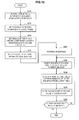
- FIG. 6 is a flow chart showing an example of a schematic process flow for encoding according to an embodiment. For the sake of brevity of description, process steps that are not directly related to technology according to the present disclosure are omitted from FIG. 6 .
- the BL encoding section 1a first performs an encoding process for the base layer to generate an encoded stream of the base layer (step S11).
- the common memory 2 buffers an image (one or both of a decoded image and a predicted error image) of the base layer generated in the encoding process for the base layer and the parameters reused between the layers (step S12).
- the parameters reused between the layers may include the resolution information, for example.
- the EL encoding section 1b performs an encoding process for the enhancement layer to generate an encoded stream of the enhancement layer (step S13).
- the image of the base layer buffered by the common memory 2 is up-sampled by the color gamut prediction section 40 so that the color gamut is converted. Then, the image of the base layer after the color gamut conversion can be used as a reference image in the inter layer prediction.
- the multiplexing section 3 multiplexes an encoded stream of the base layer generated by the BL encoding section 1a and an encoded stream of the enhancement layer generated by the EL encoding section 1b to generate a multilayer multiplexed stream (step S14).
- FIG. 7 is a flowchart showing an example of a process flow of the color gamut prediction process in the encoding process for the enhancement layer.
- the color gamut prediction process described herein can be repeated in units (for example, units of sequences, pictures, or slices) in which the lookup table is updated.
- the color gamut prediction section 40 first sets the granularity of the luma component of the lookup table according to the presetting of the user or the analysis of the image (step S20).
- the color gamut prediction section 40 sets the granularities of the first and second chroma components rougher than the granularity of the luma component (step S22).
- the color gamut prediction section 40 determines the lookup table having the set granularities for the color gamut prediction and buffers the determined lookup table in the LUT buffer 45 (step S24).
- the LUT buffer 45 maintains the lookup table determined by the color gamut prediction section 40 until subsequent updating of the lookup table.
- the color gamut prediction section 40 generates the lookup table information defining the lookup table by, for example, the syntax shown in Table 2 or 3 (step S26).
- the lookup table information generated herein includes granularity information defining the granularities (common or separate granularities) of the first and second chroma components in addition to granularity information defining the granularity of the luma component.
- the lossless encoding section 16 encodes the lookup table information generated by the color gamut prediction section 40 (step S28).
- the color gamut prediction section 40 up-samples the image of the base layer acquired from the common memory 2 according to the resolution ratio between the base layer and the enhancement layer (step S30). Subsequent processes of steps S32 to S38 are repeated for each pixel using each pixel after the up-sampling as a pixel of interest.
- the color gamut prediction section 40 first selects the sub-space of the 3-dimensional color space divided by the granularities of the three color components to which the pixel vector of the pixel of interest belongs (step S32). Next, the color gamut prediction section 40 acquires the predicted pixel value corresponding to the selected sub-space from the 3-dimensional lookup table buffered by the LUT buffer 45 (step S34). The color gamut prediction section 40 stores the acquired predicted pixel value of the pixel of interest in the frame memory 25 (step S36).
- step S38 the color gamut prediction process is repeated on the subsequent pixel of interest.
- the up-sampling may also be repeated.
- FIG. 8 is a block diagram showing an example of the configuration of the EL decoding section 6b shown in FIG. 4 .
- the EL decoding section 6b includes an accumulation buffer 61, a lossless decoding section 62, an inverse quantization section 63, an inverse orthogonal transform section 64, an addition section 65, a loop filter 66, a sorting buffer 67, a digital-to-analog (D/A) conversion section 68, a frame memory 69, selectors 70 and 71, an intra prediction section 80, an inter prediction section 85, a color gamut prediction section 90, and a LUT buffer 95.
- D/A digital-to-analog
- the accumulation buffer 61 temporarily accumulates the encoded stream of the enhancement layer input from the demultiplexing section 5 using a storage medium.
- the lossless decoding section 62 decodes the quantized data of the enhancement layer from the encoded stream of the enhancement layer input from the accumulation buffer 61 according to the encoding scheme used at the time of the encoding.
- the lossless decoding section 62 decodes the information inserted into the header region of the encoded stream.
- the information decoded by the lossless decoding section 62 can include, for example, the information regarding the intra prediction and the information regarding the inter prediction.
- the parameters for the color gamut prediction (for example, the lookup table information) can also be decoded in the enhancement layer.
- the lossless decoding section 62 outputs the quantized data to the inverse quantization section 63.
- the lossless decoding section 62 outputs the information regarding the intra prediction to the intra prediction section 80.
- the lossless decoding section 62 outputs the information regarding the inter prediction to the inter prediction section 85.
- the lossless decoding section 62 outputs the parameters for the color gamut prediction to the color gamut prediction section 90.
- the inverse quantization section 63 inversely quantizes the quantized data input from the lossless decoding section 62 in the quantization step used at the time of the encoding to restore the transform coefficient data of the enhancement layer.
- the inverse quantization section 63 outputs the restored transform coefficient data to the inverse orthogonal transform section 64.
- the inverse orthogonal transform section 64 performs an inverse orthogonal transform on the transform coefficient data input from the inverse quantization section 63 according to the orthogonal transform scheme used at the time of the encoding to generate the predicted error data.
- the inverse orthogonal transform section 64 outputs the generated predicted error data to the addition section 65.
- the addition section 65 adds the predicted error data input from the inverse orthogonal transform section 64 and the predicted image data input from the selector 71 to generate decoded image data. Then, the addition section 65 outputs the generated decoded image data to the loop filter 66 and the frame memory 69.
- the loop filter 66 includes a deblock filter that reduces block distortion, a sample adaptive offset filter that adds an offset value to each pixel value, and an adaptive loop filter that minimizes an error with the original image.
- the loop filter 66 filters the decoded image data input from the addition section 65 and outputs the decoded image data after filtering to the sorting buffer 67 and the frame memory 69.
- the sorting buffer 67 sorts the images input from the loop filter 66 to generate a chronological series of image data. Then, the sorting buffer 67 outputs the generated image data to the D/A conversion section 68.
- the D/A conversion section 68 converts the image data with a digital format input from the sorting buffer 67 into an image signal with an analog format. Then, the D/A conversion section 68 displays the image of the enhancement layer by outputting the analog image signal to, for example, a display (not shown) connected to the image decoding device 60.
- the frame memory 69 stores the decoded image data before the filtering input from the addition section 65, the decoded image data after the filtering input from the loop filter 66, and the reference image data of the base layer input from the color gamut prediction section 90 using a storage medium.
- the selector 70 switches an output destination of the image data from the frame memory 69 between the intra prediction section 80 and the inter prediction section 85 for each block in the image according to the mode information acquired by the lossless decoding section 62. For example, when the intra prediction mode is designated, the selector 70 outputs the decoded image data before the filtering supplied from the frame memory 69 as the reference image data to the intra prediction section 80. When the inter prediction mode is designated, the selector 70 outputs the decoded image data after the filtering as the reference image data to the inter prediction section 85. When the inter layer prediction is performed in the intra prediction section 80 or the inter prediction section 85, the selector 70 supplies the reference image data of the base layer to the intra prediction section 80 or the inter prediction section 85.
- the selector 71 switches an output source of the predicted image data to be supplied to the addition section 65 between the intra prediction section 80 and the inter prediction section 85 according to the mode information acquired by the lossless decoding section 62. For example, when the intra prediction mode is designated, the selector 71 supplies the predicted image data output from the intra prediction section 80 to the addition section 65. When the inter prediction mode is designated, the selector 71 supplies the predicted image data output from the inter prediction section 85 to the addition section 65.
- the intra prediction section 80 performs the intra prediction process of the enhancement layer based on the information regarding the intra prediction input from the lossless decoding section 62 and the reference image data from the frame memory 69 to generate predicted image data.
- the intra prediction process is performed for each PU.
- the intra prediction section 80 uses a co-located block in the base layer corresponding to a prediction target block as a reference block. In the case of the intra BL prediction, the intra prediction section 80 generates the predicted image based on the decoded image of the reference block.
- the intra prediction section 80 predicts a prediction error of the intra prediction based on the predicted error image of the reference block and generates the predicted image to which the predicted prediction error is added.
- the intra prediction section 80 outputs the generated predicted image data of the enhancement layer to the selector 71.
- the inter prediction section 85 performs an inter prediction process (motion compensation process) of the enhancement layer based on the information regarding the inter prediction input from the lossless decoding section 62 and the reference image data from the frame memory 69 to generate predicted image data.
- the inter prediction process is performed for each PU.
- the inter prediction section 85 uses a co-located block in the base layer corresponding to a prediction target block as a reference block.
- the inter prediction section 85 predicts a prediction error of the inter prediction based on the predicted error image of the reference block and generates a predicted image to which the predicted prediction error is added.
- the inter prediction section 85 outputs the generated predicted image data of the enhancement layer to the selector 71.
- the color gamut prediction section 90 up-samples the image (the decoded image or the predicted error image) of the base layer buffered in the common memory 7 according to a resolution ratio between the base layer and the enhancement layer.
- the color gamut prediction section 90 converts the color gamut of the up-sampled image of the base layer into the same color gamut as the image of the enhancement layer.
- the color gamut prediction section 90 uses a lookup table buffered by the LUT buffer 95 to convert the color gamut.
- the image of the base layer of which the color gamut is converted by the color gamut prediction section 90 can be stored in the frame memory 69 to be used as a reference image in the inter layer prediction by the intra prediction section 80 or the inter prediction section 85.
- the LUT buffer 95 is a buffer that buffers the lookup table used by the color gamut prediction section 90.
- the lookup table maps combinations of the luma component (Y), the first chroma component (U), and the second chroma component (V) of the base layer to the predicted pixel values of the enhancement layer corresponding to the combinations.
- the color gamut prediction section 90 uses the lookup table in which the granularities of the first and second chroma components are rougher than the granularity of the luma component for the color gamut prediction when the color gamut prediction section 90 predicts the image of the enhancement layer from the image of the base layer.
- the color space of the base layer is divided into a plurality of sub-spaces based on the granularities of the three color components and the lookup table defines the predicted pixel values (pixel vectors of the enhancement layer) corresponding to each sub-space.
- the color gamut prediction section 90 acquires the lookup table information decoded by the lossless decoding section 62.
- the lookup table information can include granularity information defining granularities to be set for the luma component (Y), the first chroma component (U), and the second chroma component (V).
- the granularity information may include one parameter commonly defining a granularity of the first and second chroma components. Instead, the granularity information may include separate parameters each defining the granularities of the first and second chroma components.
- the lookup table information may include a parameter defining the depth bit of the predicted pixel value and information defining content (mapping between input pixel values and predicted pixel values) of the lookup table.
- the color gamut prediction section 90 generates the lookup table defining the mapping between each of the plurality of sub-spaces of the color space of the base layer and the corresponding predicted pixel values based on the lookup table information and buffers the generated lookup table in the LUT buffer 95.
- the acquisition of the lookup table information and the generation of the lookup table can be performed in units of sequences, pictures, or slices.
- the lookup table information may be encoded inside the VPS or an extension thereof, the SPS or an extension thereof, the PPS or an extension thereof, or the slice header or an extension thereof in the encoded stream.
- the lookup table information may be decoded from the SEI and may be used to convert the color gamut at the time of display on a display.
- the color gamut prediction section 90 up-samples the image of the base layer acquired from the common memory 7 according to the resolution ratio between the base layer and the enhancement layer. Then, the color gamut prediction section 90 selects the sub-space to which each pixel vector of the base layer after the up-sampling belongs and acquires the predicted pixel value mapped to the selected sub-space with reference to the lockup table. The color gamut prediction section 90 converts the color gamut of the image of the base layer by repeating the process on each pixel. Then, the color gamut prediction section 90 stores the image of the base layer after the color gamut conversion as the reference image for the inter layer prediction in the frame memory 69. The up-sampling may be performed after the color gamut conversion.
- the color gamut prediction section 90 may use a lookup table in which the granularities of the first and second chroma components are rougher than the granularity of the luma component.
- the resolutions of the chroma components are lower than the resolution of the luma component, it is possible to efficiently reduce a buffer size of the lookup table while suppressing sacrifice of the encoding efficiency by reducing the granularities of only the chroma components of the lockup table.
- the color gamut prediction section 90 may use a lookup table which has a common granularity to the luma component, the first chroma component, and the second chroma component, as in the known method.
- FIG. 9 is a flow chart showing an example of a schematic process flow at the time of the decoding according to an embodiment. For the sake of brevity of description, process steps not directly relevant to the technology in the present disclosure are omitted from the drawing.
- the demultiplexing section 5 first demultiplexes the multilayer multiplexed stream into the encoded stream of the base layer and the encoded stream of the enhancement layer (step S60).
- the BL decoding section 6a performs the decoding process of the base layer to reconstruct the image of the base layer from the encoded steam of the base layer (step S61).
- the common memory 7 buffers an image (one or both of a decoded image and a predicted error image) of the base layer generated in the decoding process for the base layer and the parameters reused between the layers (step S62).
- the parameters reused between the layers may include the resolution information, for example.
- the EL decoding section 6b performs the decoding process for the enhancement layer to reconstruct the image of the enhancement layer (step S63).
- the image of the base layer buffered by the common memory 7 is up-sampled by the color gamut prediction section 90 so that the color gamut is converted.
- the image of the base layer after the color gamut conversion can be used as a reference image in the inter layer prediction.
- FIG. 10 is a flowchart showing an example of a process flow of the color gamut prediction process in the decoding process for the enhancement layer.
- the color gamut prediction process described herein can be repeated in units (for example, units of sequences, pictures, or slices) in which the lookup table is updated.
- the lossless decoding section 62 first decodes the lookup table information including the granularity information from the header region of the encoded stream (step S70).
- the color gamut prediction section 90 sets the granularity of the luma component of the lookup table according to the decoded granularity information (step S72).
- the color gamut prediction section 90 sets the granularities of the first and second chroma components rougher than the granularity of the luma component according to the decoded granularity information (step S74).
- the color gamut prediction section 90 reconstructs (sets) the lockup table having the set granularities and buffers the reconstructed lookup table in the LUT buffer 95 (step S76).
- the LUT buffer 95 maintains the lookup table reconstructed by the color gamut prediction section 90 until subsequent updating.
- the color gamut prediction section 90 up-samples the image of the base layer acquired from the common memory 7 according to the resolution ratio between the base layer and the enhancement layer (step S80). Subsequent processes of steps S82 to S88 are repeated for each pixel using each pixel after the up-sampling as a pixel of interest.
- the color gamut prediction section 90 first selects the sub-space of the 3-dimensional color space divided by the granularities of the three color components to which the pixel vector of the pixel of interest belongs (step S82). Next, the color gamut prediction section 90 acquires the predicted pixel value corresponding to the selected sub-space from the 3-dimensional lookup table buffered by the LUT buffer 95 (step S84). The color gamut prediction section 90 stores the acquired predicted pixel value of the pixel of interest in the frame memory 69 (step S86).
- step S88 the color gamut prediction process is repeated on the subsequent pixel of interest.
- the up-sampling may also be repeated.
- the lookup table in which the granularities of the chroma components are rougher than the granularity of the luma component is used for image prediction between the layers can be applied not only to the color gamut scalability but also to other kinds of scalable encoding.
- a pixel dynamic range is an important attribute which has an influence on an image quality.
- the maximum luminance of a Standard Dynamic Range (SDR) image supported by many known displays is 100 nits.
- the maximum luminance of a High Dynamic Range (HDR) image supported by high-end displays available in the latest markets reaches, for example, 800 nits.
- An SDR image is called a Low Dynamic Range (LDR) image in contrast to an HDR image.
- FIG. 11 is an explanatory view illustrating a dynamic range of a video format.
- the vertical axis of FIG. 11 represents luminance [nits].
- the maximum luminance of the natural world reaches 20000 nits and the maximum luminance of a general subject is, for example, about 12000 nits.
- the upper limit of the dynamic range of an image sensor is lower than the maximum luminance of the natural world and can be, for example, 4000 nits.
- An image signal generated by an image sensor is further recorded in a predetermined video format.
- the dynamic range of an SDR image is shown by a bar shaded with diagonal lines in the drawing and the upper limit of this dynamic range is 100 nits.
- a luminance dynamic range is considerably compressed by, for example, a method such as knee compression.
- the maximum luminance which can be expressed by a display is 1000 nits
- scaling is performed 10 times at the time of display of an SDR image.
- the dynamic range of an HDR image is shown by a thick-frame bar in the drawing and the upper limit of this dynamic range is 800 nits.
- a luminance dynamic range is also compressed by, for example, a method such as knee compression.
- the maximum luminance which can be expressed by a display is 1000 nits
- scaling is performed 1.25 times at the time of display of an HDR image.
- a scaling ratio is small, the deterioration in the image quality of a display image is small.
- an HDR image is supported as a video format, there is a benefit that high-quality images can be supplied to users.
- a scalable encoding technology called dynamic range scalability.
- an SDR image is transmitted with the base layer and information for restoring an HDR image from the SDR image is transmitted with the enhancement layer.
- the enhancement layer In order to restore an HDR image from an SDR image, it is important to keep mounting as simple as possible and ensure format versatility and scalability.
- an EL encoding section 101b shown in FIG. 12 may be used instead of the EL encoding section 1b shown in FIG. 3 .
- the EL encoding section 101b includes a sorting buffer 11, a subtraction section 13, an orthogonal transform section 14, a quantization section 15, a lossless encoding section 16, an accumulation buffer 17, a rate control section 18, an inverse quantization section 21, an inverse orthogonal transform section 22, an addition section 23, a loop filter 24, a frame memory 25, selectors 26 and 27, an intra prediction section 30, an inter prediction section 35, a dynamic range (DR) prediction section 140, and an LUT buffer 45.
- DR dynamic range
- the DR prediction section 140 up-samples the image of the base layer buffered by the common memory 2 according to the resolution ratio between the base layer and the enhancement layer.
- the DR prediction section 140 converts the dynamic range of the up-sampled image of the base layer into the same range as that of the image of the enhancement layer.
- the DR prediction section 140 uses the lookup table buffered by the LUT buffer 45 to convert the dynamic range.
- the image of the base layer of which the dynamic range is converted by the DR prediction section 140 can be stored in the frame memory 25 to be used as a reference image in the inter layer prediction by the intra prediction section 30 or the inter prediction section 35.
- an EL decoding section 106b shown in FIG. 13 may be used instead of the EL decoding section 6b shown in FIG. 4 .
- the EL decoding section 106b includes an accumulation buffer 61, a lossless decoding section 62, an inverse quantization section 63, an inverse orthogonal transform section 64, an addition section 65, a loop filter 66, a sorting buffer 67, a D/A conversion section 68, a frame memory 69, selectors 70 and 71, an intra prediction section 80, an inter prediction section 85, a DR prediction section 190, and an LUT buffer 95.
- the DR prediction section 190 up-samples the image of the base layer buffered by the common memory 7 according to the resolution ratio between the base layer and the enhancement layer.
- the DR prediction section 190 converts the dynamic range of the up-sampled image of the base layer into the same range as that of the image of the enhancement layer.
- the DR prediction section 190 uses the lookup table buffered by the LUT buffer 95 to convert the dynamic range.
- the image of the base layer of which the dynamic range is converted by the DR prediction section 190 can be stored in the frame memory 69 to be used as a reference image in the inter layer prediction by the intra prediction section 80 or the inter prediction section 85.
- DR prediction sections 140 and 190 use the lookup table in which the granularities of the first and second chroma components are rougher than the granularity of the luma component.
- a combination of the granularities of the three color components may be any of the combinations described above in association with the color gamut scalability.
- the LUT buffers 45 and 95 buffer a lockup table for dynamic range (DR) prediction which defines mappings between the sub-spaces of the color space of the base layer divided based on the granularities and the corresponding predicted pixel values.
- DR dynamic range
- the DR prediction section 140 of the EL encoding section 101b can generate lookup table information including one parameter (for example, nbp_code_Luma) defining the granularity of the luma component and one parameter (for example, nbp_code_Chroma) defining the granularity of the chroma components.
- one parameter for example, nbp_code_Luma
- the DR prediction section 140 can generate lookup table information including one parameter (for example, nbp_code_Y) defining the granularity of the luma component and two parameters (for example, nbp_code_U and nbp_code_V) defining the granularities of the first and second chroma components.
- one parameter for example, nbp_code_Y
- two parameters for example, nbp_code_U and nbp_code_V
- the lookup table information can be encoded by the lossless encoding section 16 and can be transmitted inside the VPS or an extension thereof, the SPS or an extension thereof, the PPS or an extension thereof, the slice header or an extension thereof, or the SEI.
- the transmitted lookup table information for the DR prediction can be decoded by the lossless decoding section 62 in the EL decoding section 106b and can be used so that the lookup table is generated by the DR prediction section 190.
- the granularity of each color component of the lookup table may also be switched depending on the chroma format. For example, when the chroma format indicates that the resolutions of the first and second chroma components are lower than the resolution of the luma component, the lookup table in which the granularities of the first and second chroma components are rougher than the granularity of the luma component can be used. On the other hand, when the chroma format indicates that the resolutions of the first and second chroma components are the same as the resolution of the luma component, the lookup table in which the granularities of the three color components are the same can be used.
- the image encoding device 10 and the image decoding device 60 may be applied to various electronic appliances such as a transmitter and a receiver for satellite broadcasting, cable broadcasting such as cable TV, distribution on the Internet, distribution to terminals via cellular communication, and the like, a recording device that records images in a medium such as an optical disc, a magnetic disk or a flash memory, a reproduction device that reproduces images from such storage medium, and the like.
- various electronic appliances such as a transmitter and a receiver for satellite broadcasting, cable broadcasting such as cable TV, distribution on the Internet, distribution to terminals via cellular communication, and the like
- a recording device that records images in a medium such as an optical disc, a magnetic disk or a flash memory
- reproduction device that reproduces images from such storage medium, and the like.
- FIG. 14 is a diagram illustrating an example of a schematic configuration of a television device applying the aforementioned embodiment.
- a television device 900 includes an antenna 901, a tuner 902, a demultiplexer 903, a decoder 904, a video signal processing unit 905, a display 906, an audio signal processing unit 907, a speaker 908, an external interface 909, a control unit 910, a user interface 911, and a bus 912.
- the tuner 902 extracts a signal of a desired channel from a broadcast signal received through the antenna 901 and demodulates the extracted signal.
- the tuner 902 then outputs an encoded bit stream obtained by the demodulation to the demultiplexer 903. That is, the tuner 902 has a role as transmission means receiving the encoded stream in which an image is encoded, in the television device 900.
- the demultiplexer 903 isolates a video stream and an audio stream in a program to be viewed from the encoded bit stream and outputs each of the isolated streams to the decoder 904.
- the demultiplexer 903 also extracts auxiliary data such as an EPG (Electronic Program Guide) from the encoded bit stream and supplies the extracted data to the control unit 910.
- EPG Electronic Program Guide
- the demultiplexer 903 may descramble the encoded bit stream when it is scrambled.
- the decoder 904 decodes the video stream and the audio stream that are input from the demultiplexer 903. The decoder 904 then outputs video data generated by the decoding process to the video signal processing unit 905. Furthermore, the decoder 904 outputs audio data generated by the decoding process to the audio signal processing unit 907.
- the video signal processing unit 905 reproduces the video data input from the decoder 904 and displays the video on the display 906.
- the video signal processing unit 905 may also display an application screen supplied through the network on the display 906.
- the video signal processing unit 905 may further perform an additional process such as noise reduction on the video data according to the setting.
- the video signal processing unit 905 may generate an image of a GUI (Graphical User Interface) such as a menu, a button, or a cursor and superpose the generated image onto the output image.
- GUI Graphic User Interface
- the display 906 is driven by a drive signal supplied from the video signal processing unit 905 and displays video or an image on a video screen of a display device (such as a liquid crystal display, a plasma display, or an OELD (Organic ElectroLuminescence Display)).
- a display device such as a liquid crystal display, a plasma display, or an OELD (Organic ElectroLuminescence Display)
- the audio signal processing unit 907 performs a reproducing process such as D/A conversion and amplification on the audio data input from the decoder 904 and outputs the audio from the speaker 908.
- the audio signal processing unit 907 may also perform an additional process such as noise reduction on the audio data.
- the external interface 909 is an interface that connects the television device 900 with an external device or a network.
- the decoder 904 may decode a video stream or an audio stream received through the external interface 909. This means that the external interface 909 also has a role as the transmission means receiving the encoded stream in which an image is encoded, in the television device 900.
- the control unit 910 includes a processor such as a CPU and a memory such as a RAM and a ROM.
- the memory stores a program executed by the CPU, program data, EPG data, and data acquired through the network.
- the program stored in the memory is read by the CPU at the start-up of the television device 900 and executed, for example.
- the CPU controls the operation of the television device 900 in accordance with an operation signal that is input from the user interface 911, for example.
- the user interface 911 is connected to the control unit 910.
- the user interface 911 includes a button and a switch for a user to operate the television device 900 as well as a reception part which receives a remote control signal, for example.
- the user interface 911 detects a user operation through these components, generates the operation signal, and outputs the generated operation signal to the control unit 910.
- the bus 912 mutually connects the tuner 902, the demultiplexer 903, the decoder 904, the video signal processing unit 905, the audio signal processing unit 907, the external interface 909, and the control unit 910.
- the decoder 904 in the television device 900 configured in the aforementioned manner has a function of the image decoding device 60 according to the aforementioned embodiment.
- the buffer size for a lookup table can be reduced.
- FIG. 15 is a diagram illustrating an example of a schematic configuration of a mobile telephone applying the aforementioned embodiment.
- a mobile telephone 920 includes an antenna 921, a communication unit 922, an audio codec 923, a speaker 924, a microphone 925, a camera unit 926, an image processing unit 927, a demultiplexing unit 928, a recording/reproducing unit 929, a display 930, a control unit 931, an operation unit 932, and a bus 933.
- the antenna 921 is connected to the communication unit 922.
- the speaker 924 and the microphone 925 are connected to the audio codec 923.
- the operation unit 932 is connected to the control unit 931.
- the bus 933 mutually connects the communication unit 922, the audio codec 923, the camera unit 926, the image processing unit 927, the demultiplexing unit 928, the recording/reproducing unit 929, the display 930, and the control unit 931.
- the mobile telephone 920 performs an operation such as transmitting/receiving an audio signal, transmitting/receiving an electronic mail or image data, imaging an image, or recording data in various operation modes including an audio call mode, a data communication mode, a photography mode, and a videophone mode.
- an analog audio signal generated by the microphone 925 is supplied to the audio codec 923.
- the audio codec 923 then converts the analog audio signal into audio data, performs A/D conversion on the converted audio data, and compresses the data.
- the audio codec 923 thereafter outputs the compressed audio data to the communication unit 922.
- the communication unit 922 encodes and modulates the audio data to generate a transmission signal.
- the communication unit 922 then transmits the generated transmission signal to a base station (not shown) through the antenna 921.
- the communication unit 922 amplifies a radio signal received through the antenna 921, converts a frequency of the signal, and acquires a reception signal.
- the communication unit 922 thereafter demodulates and decodes the reception signal to generate the audio data and output the generated audio data to the audio codec 923.
- the audio codec 923 expands the audio data, performs D/A conversion on the data, and generates the analog audio signal.
- the audio codec 923 then outputs the audio by supplying the generated audio signal to the speaker 924.
- the control unit 931 In the data communication mode, for example, the control unit 931 generates character data configuring an electronic mail, in accordance with a user operation through the operation unit 932. The control unit 931 further displays a character on the display 930. Moreover, the control unit 931 generates electronic mail data in accordance with a transmission instruction from a user through the operation unit 932 and outputs the generated electronic mail data to the communication unit 922.
- the communication unit 922 encodes and modulates the electronic mail data to generate a transmission signal. Then, the communication unit 922 transmits the generated transmission signal to the base station (not shown) through the antenna 921.
- the communication unit 922 further amplifies a radio signal received through the antenna 921, converts a frequency of the signal, and acquires a reception signal.
- the communication unit 922 thereafter demodulates and decodes the reception signal, restores the electronic mail data, and outputs the restored electronic mail data to the control unit 931.
- the control unit 931 displays the content of the electronic mail on the display 930 as well as stores the electronic mail data in a storage medium of the recording/reproducing unit 929.
- the recording/reproducing unit 929 includes an arbitrary storage medium that is readable and writable.
- the storage medium may be a built-in storage medium such as a RAM or a flash memory, or may be an externally-mounted storage medium such as a hard disk, a magnetic disk, a magneto-optical disk, an optical disk, a USB (Unallocated Space Bitmap) memory, or a memory card.
- the camera unit 926 images an object, generates image data, and outputs the generated image data to the image processing unit 927.
- the image processing unit 927 encodes the image data input from the camera unit 926 and stores an encoded stream in the storage medium of the recording/reproducing unit 929.
- the demultiplexing unit 928 multiplexes a video stream encoded by the image processing unit 927 and an audio stream input from the audio codec 923, and outputs the multiplexed stream to the communication unit 922.
- the communication unit 922 encodes and modulates the stream to generate a transmission signal.
- the communication unit 922 subsequently transmits the generated transmission signal to the base station (not shown) through the antenna 921.
- the communication unit 922 amplifies a radio signal received through the antenna 921, converts a frequency of the signal, and acquires a reception signal.
- the transmission signal and the reception signal can include an encoded bit stream.
- the communication unit 922 demodulates and decodes the reception signal to restore the stream, and outputs the restored stream to the demultiplexing unit 928.
- the demultiplexing unit 928 isolates the video stream and the audio stream from the input stream and outputs the video stream and the audio stream to the image processing unit 927 and the audio codec 923, respectively.
- the image processing unit 927 decodes the video stream to generate video data.
- the video data is then supplied to the display 930, which displays a series of images.
- the audio codec 923 expands and performs D/A conversion on the audio stream to generate an analog audio signal.
- the audio codec 923 then supplies the generated audio signal to the speaker 924 to output the audio.
- the image processing unit 927 in the mobile telephone 920 configured in the aforementioned manner has a function of the image encoding device 10 and the image decoding device 60 according to the aforementioned embodiment.
- the buffer size for a lookup table can be reduced.
- FIG. 16 is a diagram illustrating an example of a schematic configuration of a recording/reproducing device applying the aforementioned embodiment.
- a recording/reproducing device 940 encodes audio data and video data of a broadcast program received and records the data into a recording medium, for example.
- the recording/reproducing device 940 may also encode audio data and video data acquired from another device and record the data into the recording medium, for example.
- the recording/reproducing device 940 reproduces the data recorded in the recording medium on a monitor and a speaker.
- the recording/reproducing device 940 at this time decodes the audio data and the video data.
- the recording/reproducing device 940 includes a tuner 941, an external interface 942, an encoder 943, an HDD (Hard Disk Drive) 944, a disk drive 945, a selector 946, a decoder 947, an OSD (On-Screen Display) 948, a control unit 949, and a user interface 950.
- the tuner 941 extracts a signal of a desired channel from a broadcast signal received through an antenna (not shown) and demodulates the extracted signal.
- the tuner 941 then outputs an encoded bit stream obtained by the demodulation to the selector 946. That is, the tuner 941 has a role as transmission means in the recording/reproducing device 940.
- the external interface 942 is an interface which connects the recording/reproducing device 940 with an external device or a network.
- the external interface 942 may be, for example, an IEEE 1394 interface, a network interface, a USB interface, or a flash memory interface.
- the video data and the audio data received through the external interface 942 are input to the encoder 943, for example. That is, the external interface 942 has a role as transmission means in the recording/reproducing device 940.
- the encoder 943 encodes the video data and the audio data when the video data and the audio data input from the external interface 942 are not encoded.
- the encoder 943 thereafter outputs an encoded bit stream to the selector 946.
- the HDD 944 records, into an internal hard disk, the encoded bit stream in which content data such as video and audio is compressed, various programs, and other data.
- the HDD 944 reads these data from the hard disk when reproducing the video and the audio.
- the disk drive 945 records and reads data into/from a recording medium which is mounted to the disk drive.
- the recording medium mounted to the disk drive 945 may be, for example, a DVD disk (such as DVD-Video, DVD-RAM, DVD-R, DVD-RW, DVD+R, or DVD+RW) or a Blu-ray (Registered Trademark) disk.
- the selector 946 selects the encoded bit stream input from the tuner 941 or the encoder 943 when recording the video and audio, and outputs the selected encoded bit stream to the HDD 944 or the disk drive 945.
- the selector 946 outputs the encoded bit stream input from the HDD 944 or the disk drive 945 to the decoder 947.
- the decoder 947 decodes the encoded bit stream to generate the video data and the audio data.
- the decoder 904 then outputs the generated video data to the OSD 948 and the generated audio data to an external speaker.
- the OSD 948 reproduces the video data input from the decoder 947 and displays the video.
- the OSD 948 may also superpose an image of a GUI such as a menu, a button, or a cursor onto the video displayed.
- the control unit 949 includes a processor such as a CPU and a memory such as a RAM and a ROM.
- the memory stores a program executed by the CPU as well as program data.
- the program stored in the memory is read by the CPU at the start-up of the recording/reproducing device 940 and executed, for example.
- the CPU controls the operation of the recording/reproducing device 940 in accordance with an operation signal that is input from the user interface 950, for example.
- the user interface 950 is connected to the control unit 949.
- the user interface 950 includes a button and a switch for a user to operate the recording/reproducing device 940 as well as a reception part which receives a remote control signal, for example.
- the user interface 950 detects a user operation through these components, generates the operation signal, and outputs the generated operation signal to the control unit 949.
- the encoder 943 in the recording/reproducing device 940 configured in the aforementioned manner has a function of the image encoding device 10 according to the aforementioned embodiment.
- the decoder 947 has a function of the image decoding device 60 according to the aforementioned embodiment.
- FIG. 17 shows an example of a schematic configuration of an image capturing device applying the aforementioned embodiment.
- An imaging device 960 images an object, generates an image, encodes image data, and records the data into a recording medium.
- the imaging device 960 includes an optical block 961, an imaging unit 962, a signal processing unit 963, an image processing unit 964, a display 965, an external interface 966, a memory 967, a media drive 968, an OSD 969, a control unit 970, a user interface 971, and a bus 972.
- the optical block 961 is connected to the imaging unit 962.
- the imaging unit 962 is connected to the signal processing unit 963.
- the display 965 is connected to the image processing unit 964.
- the user interface 971 is connected to the control unit 970.
- the bus 972 mutually connects the image processing unit 964, the external interface 966, the memory 967, the media drive 968, the OSD 969, and the control unit 970.
- the optical block 961 includes a focus lens and a diaphragm mechanism.
- the optical block 961 forms an optical image of the object on an imaging surface of the imaging unit 962.
- the imaging unit 962 includes an image sensor such as a CCD (Charge Coupled Device) or a CMOS (Complementary Metal Oxide Semiconductor) and performs photoelectric conversion to convert the optical image formed on the imaging surface into an image signal as an electric signal. Subsequently, the imaging unit 962 outputs the image signal to the signal processing unit 963.
- CCD Charge Coupled Device
- CMOS Complementary Metal Oxide Semiconductor
- the signal processing unit 963 performs various camera signal processes such as a knee correction, a gamma correction and a color correction on the image signal input from the imaging unit 962.
- the signal processing unit 963 outputs the image data, on which the camera signal process has been performed, to the image processing unit 964.
- the image processing unit 964 encodes the image data input from the signal processing unit 963 and generates the encoded data.
- the image processing unit 964 then outputs the generated encoded data to the external interface 966 or the media drive 968.
- the image processing unit 964 also decodes the encoded data input from the external interface 966 or the media drive 968 to generate image data.
- the image processing unit 964 then outputs the generated image data to the display 965.
- the image processing unit 964 may output to the display 965 the image data input from the signal processing unit 963 to display the image.
- the image processing unit 964 may superpose display data acquired from the OSD 969 onto the image that is output on the display 965.
- the OSD 969 generates an image of a GUI such as a menu, a button, or a cursor and outputs the generated image to the image processing unit 964.
- the external interface 966 is configured as a USB input/output terminal, for example.
- the external interface 966 connects the imaging device 960 with a printer when printing an image, for example.
- a drive is connected to the external interface 966 as needed.
- a removable medium such as a magnetic disk or an optical disk is mounted to the drive, for example, so that a program read from the removable medium can be installed to the imaging device 960.
- the external interface 966 may also be configured as a network interface that is connected to a network such as a LAN or the Internet. That is, the external interface 966 has a role as transmission means in the imaging device 960.
- the recording medium mounted to the media drive 968 may be an arbitrary removable medium that is readable and writable such as a magnetic disk, a magneto-optical disk, an optical disk, or a semiconductor memory. Furthermore, the recording medium may be fixedly mounted to the media drive 968 so that a non-transportable storage unit such as a built-in hard disk drive or an SSD (Solid State Drive) is configured, for example.
- a non-transportable storage unit such as a built-in hard disk drive or an SSD (Solid State Drive) is configured, for example.
- the control unit 970 includes a processor such as a CPU and a memory such as a RAM and a ROM.
- the memory stores a program executed by the CPU as well as program data.
- the program stored in the memory is read by the CPU at the start-up of the imaging device 960 and then executed.
- the CPU controls the operation of the imaging device 960 in accordance with an operation signal that is input from the user interface 971, for example.
- the user interface 971 is connected to the control unit 970.
- the user interface 971 includes a button and a switch for a user to operate the imaging device 960, for example.
- the user interface 971 detects a user operation through these components, generates the operation signal, and outputs the generated operation signal to the control unit 970.
- the image processing unit 964 in the imaging device 960 configured in the aforementioned manner has a function of the image encoding device 10 and the image decoding device 60 according to the aforementioned embodiment.
- the imaging device 960 performs the color gamut prediction on the layers of which the color gamuts are mutually different, the buffer size for a lookup table can be reduced.
- a data transmission system 1000 includes a stream storage device 1001 and a delivery server 1002.
- the delivery server 1002 is connected to some terminal devices via a network 1003.
- the network 1003 may be a wire network or a wireless network or a combination thereof.
- FIG. 18 shows a PC (Personal Computer) 1004, an AV device 1005, a tablet device 1006, and a mobile phone 1007 as examples of the terminal devices.
- PC Personal Computer
- the stream storage device 1001 stores, for example, stream data 1011 including a multiplexed stream generated by the image encoding device 10.
- the multiplexed stream includes an encoded stream of the base layer (BL) and an encoded stream of an enhancement layer (EL).
- the delivery server 1002 reads the stream data 1011 stored in the stream storage device 1001 and delivers at least a portion of the read stream data 1011 to the PC 1004, the AV device 1005, the tablet device 1006, and the mobile phone 1007 via the network 1003.
- the delivery server 1002 selects the stream to be delivered based on some condition such as capabilities of a terminal device or the communication environment. For example, the delivery server 1002 may avoid a delay in a terminal device or an occurrence of overflow or overload of a processor by not delivering an encoded stream having high image quality exceeding image quality that can be handled by the terminal device. The delivery server 1002 may also avoid occupation of communication bands of the network 1003 by not delivering an encoded stream having high image quality. On the other hand, when there is no risk to be avoided or it is considered to be appropriate based on a user's contract or some condition, the delivery server 1002 may deliver an entire multiplexed stream to a terminal device.
- the delivery server 1002 reads the stream data 1011 from the stream storage device 1001. Then, the delivery server 1002 delivers the stream data 1011 directly to the PC 1004 having high processing capabilities. Because the AV device 1005 has low processing capabilities, the delivery server 1002 generates stream data 1012 containing only an encoded stream of the base layer extracted from the stream data 1011 and delivers the stream data 1012 to the AV device 1005. The delivery server 1002 delivers the stream data 1011 directly to the tablet device 1006 capable of communication at a high communication rate. Because the mobile phone 1007 can communicate at a low communication rate, the delivery server 1002 delivers the stream data 1012 containing only an encoded stream of the base layer to the mobile phone 1007.
- the amount of traffic to be transmitted can adaptively be adjusted.
- the code amount of the stream data 1011 is reduced when compared with a case when each layer is individually encoded and thus, even if the whole stream data 1011 is delivered, the load on the network 1003 can be lessened. Further, memory resources of the stream storage device 1001 are saved.
- Hardware performance of the terminal devices is different from device to device.
- capabilities of applications run on the terminal devices are diverse.
- communication capacities of the network 1003 are varied. Capacities available for data transmission may change every moment due to other traffic.
- the delivery server 1002 may acquire terminal information about hardware performance and application capabilities of terminal devices and network information about communication capacities of the network 1003 through signaling with the delivery destination terminal device. Then, the delivery server 1002 can select the stream to be delivered based on the acquired information.
- the layer to be decoded may be extracted by the terminal device.
- the PC 1004 may display a base layer image extracted and decoded from a received multiplexed stream on the screen thereof. After generating the stream data 1012 by extracting an encoded stream of the base layer from a received multiplexed stream, the PC 1004 may cause a storage medium to store the stream data 1012 or transfer the stream data to another device.
- the configuration of the data transmission system 1000 shown in FIG. 18 is only an example.
- the data transmission system 1000 may include any numbers of the stream storage device 1001, the delivery server 1002, the network 1003, and terminal devices.
- a data transmission system 1100 includes a broadcasting station 1101 and a terminal device 1102.
- the broadcasting station 1101 broadcasts an encoded stream 1121 of the base layer on a terrestrial channel 1111.
- the broadcasting station 1101 also broadcasts an encoded stream 1122 of an enhancement layer to the terminal device 1102 via a network 1112.
- the terminal device 1102 has a receiving function to receive terrestrial broadcasting broadcast by the broadcasting station 1101 and receives the encoded stream 1121 of the base layer via the terrestrial channel 1111.
- the terminal device 1102 also has a communication function to communicate with the broadcasting station 1101 and receives the encoded stream 1122 of an enhancement layer via the network 1112.
- the terminal device 1102 may decode a base layer image from the received encoded stream 1121 and display the base layer image on the screen. Alternatively, the terminal device 1102 may cause a storage medium to store the decoded base layer image or transfer the base layer image to another device.
- the terminal device 1102 may generate a multiplexed stream by multiplexing the encoded stream 1121 of the base layer and the encoded stream 1122 of an enhancement layer.
- the terminal device 1102 may also decode an enhancement image from the encoded stream 1122 of an enhancement layer to display the enhancement image on the screen.
- the terminal device 1102 may cause a storage medium to store the decoded enhancement layer image or transfer the enhancement layer image to another device.
- an encoded stream of each layer contained in a multiplexed stream can be transmitted via a different communication channel for each layer. Accordingly, a communication delay or an occurrence of overflow can be reduced by distributing loads on individual channels.
- the communication channel to be used for transmission may dynamically be selected in accordance with some condition.
- the encoded stream 1121 of the base layer whose data amount is relatively large may be transmitted via a communication channel having a wider bandwidth and the encoded stream 1122 of an enhancement layer whose data amount is relatively small may be transmitted via a communication channel having a narrower bandwidth.
- the communication channel on which the encoded stream 1122 of a specific layer is transmitted may be switched in accordance with the bandwidth of the communication channel. Accordingly, the load on individual channels can be lessened more effectively.
- the configuration of the data transmission system 1100 shown in FIG. 19 is only an example.
- the data transmission system 1100 may include any numbers of communication channels and terminal devices.
- the configuration of the system described here may also be applied to other uses than broadcasting.
- a data transmission system 1200 includes an imaging device 1201 and a stream storage device 1202.
- the imaging device 1201 scalable-encodes image data generated by a subject 1211 being imaged to generate a multiplexed stream 1221.
- the multiplexed stream 1221 includes an encoded stream of the base layer and an encoded stream of an enhancement layer. Then, the imaging device 1201 supplies the multiplexed stream 1221 to the stream storage device 1202.
- the stream storage device 1202 stores the multiplexed stream 1221 supplied from the imaging device 1201 in different image quality for each mode. For example, the stream storage device 1202 extracts the encoded stream 1222 of the base layer from the multiplexed stream 1221 in normal mode and stores the extracted encoded stream 1222 of the base layer. In high quality mode, by contrast, the stream storage device 1202 stores the multiplexed stream 1221 as it is. Accordingly, the stream storage device 1202 can store a high-quality stream with a large amount of data only when recording of video in high quality is desired. Therefore, memory resources can be saved while the influence of image degradation on users is curbed.
- the imaging device 1201 is assumed to be a surveillance camera.
- the normal mode is selected.
- the captured image is likely to be unimportant and priority is given to the reduction of the amount of data so that the video is recorded in low image quality (that is, only the encoded stream 1222 of the base layer is stored).
- the high-quality mode is selected. In this case, the captured image is likely to be important and priority is given to high image quality so that the video is recorded in high image quality (that is, the multiplexed stream 1221 is stored).
- the mode is selected by the stream storage device 1202 based on, for example, an image analysis result.
- the imaging device 1201 may select the mode. In the latter case, imaging device 1201 may supply the encoded stream 1222 of the base layer to the stream storage device 1202 in normal mode and the multiplexed stream 1221 to the stream storage device 1202 in high-quality mode.
- Selection criteria for selecting the mode may be any criteria.
- the mode may be switched in accordance with the loudness of voice acquired through a microphone or the waveform of voice.
- the mode may also be switched periodically.
- the mode may be switched in response to user's instructions.
- the number of selectable modes may be any number as long as the number of hierarchized layers is not exceeded.
- the configuration of the data transmission system 1200 shown in FIG. 20 is only an example.
- the data transmission system 1200 may include any number of the imaging device 1201.
- the configuration of the system described here may also be applied to other uses than the surveillance camera.
- the multi-view codec is a kind of multi-layer codec and is an image encoding system to encode and decode so-called multi-view video.
- FIG. 21 is an explanatory view illustrating a multi-view codec. Referring to FIG. 21 , sequences of three view frames captured from three viewpoints are shown. A view ID (view_id) is attached to each view. Among a plurality of these views, one view is specified as the base view. Views other than the base view are called non-base views. In the example of FIG. 21 , the view whose view ID is "0" is the base view and two views whose view ID is "1" or "2" are non-base views. When these views are hierarchically encoded, each view may correspond to a layer. As indicated by arrows in FIG. 21 , an image of a non-base view is encoded and decoded by referring to an image of the base view (an image of the other non-base view may also be referred to).
- FIG. 22 is a block diagram showing a schematic configuration of an image encoding device 10v supporting the multi-view codec.
- the image encoding device 10v includes a first layer encoding section 1c, a second layer encoding section 1d, the common memory 2, and the multiplexing section 3.
- the function of the first layer encoding section 1c is the same as that of the BL encoding section 1a described using FIG. 3 except that, instead of a base layer image, a base view image is received as input.
- the first layer encoding section 1c encodes the base view image to generate an encoded stream of a first layer.
- the function of the second layer encoding section 1d is the same as that of the EL encoding section 1b described using FIG. 3 except that, instead of an enhancement layer image, a non-base view image is received as input.
- the second layer encoding section 1d encodes the non-base view image to generate an encoded stream of a second layer.
- the common memory 2 stores information commonly used between layers.
- the multiplexing section 3 multiplexes an encoded stream of the first layer generated by the first layer encoding section 1c and an encoded stream of the second layer generated by the second layer encoding section 1d to generate a multilayer multiplexed stream.
- FIG. 23 is a block diagram showing a schematic configuration of an image decoding device 60v supporting the multi-view codec.
- the image decoding device 60v includes the demultiplexing section 5, a first layer decoding section 6c, a second layer decoding section 6d, and the common memory 7.
- the demultiplexing section 5 demultiplexes a multilayer multiplexed stream into an encoded stream of the first layer and an encoded stream of the second layer.
- the function of the first layer decoding section 6c is the same as that of the BL decoding section 6a described using FIG. 4 except that an encoded stream in which, instead of a base layer image, a base view image is encoded is received as input.
- the first layer decoding section 6c decodes a base view image from an encoded stream of the first layer.
- the function of the second layer decoding section 6d is the same as that of the EL decoding section 6b described using FIG. 4 except that an encoded stream in which, instead of an enhancement layer image, a non-base view image is encoded is received as input.
- the second layer decoding section 6d decodes a non-base view image from an encoded stream of the second layer.
- the common memory 7 stores information commonly used between layers.
- the buffer size for a lookup table can be reduced in the multi-view codec.
- Technology in the present disclosure may also be applied to a streaming protocol.
- MPEG-DASH Dynamic Adaptive Streaming over HTTP
- a plurality of encoded streams having mutually different parameters such as the resolution is prepared by a stream server in advance.
- the streaming server dynamically selects appropriate data for streaming from the plurality of encoded streams and delivers the selected data.
- the prediction of the color gamut between the encoded streams may be controlled according to the technology in the present disclosure.
- the lookup table in which the granularities of the first and second chroma components are rougher than the granularity of the luma component is used when the image of the second layer having the different color gamut (or dynamic range) from the first layer is predicted from the image of the first layer using the lockup table which maps combinations of the luma component, the first chroma component, and the second chroma component of the first layer to the predicted pixel values of the second layer corresponding to the combinations.
- the size of the buffer buffering the lookup table can be reduced compared to when the lookup table in which the granularities of the three color components are mutually the same is used.
- the image resolutions of the chroma components to be lower than the image resolution of the luma component and allowing only the granularities of the chroma components to be rougher while maintaining the fine granularity of the luma component, it is possible to lessen the influence of the deterioration in the prediction precision caused due to the reduction in the granularities.
- the lookup table information associated with the granularities of the first and second chroma components of the lookup table is encoded and decoded separately from the granularity of the luma component.
- the resolution is different for each color component and the degree of reduction in the buffer size can be flexibly adjusted in accordance with various conditions such as the requisites regarding the encoding efficiency or restrictions of the memory resources.
- CU refers to logical units including a syntax associated with an individual block in HEVC.
- the blocks may be referred to with the terms “coding block (CB),” “prediction block (PB),” and “transform block (TB).”
- CB is formed by hierarchically dividing a coding tree block (CTB) in a quad-tree shape. The one entire quad-tree corresponds to the CTB and a logical unit corresponding to the CTB is referred to as a coding tree unit (CTU).
- the CTB and the CB in HEVC have a similar role to a macro block in H.264/AVC in that the CTB and the CB are processing units of an encoding process.
- the CTB and the CB are different from the macro block in that the sizes of the CTB and the CB are not fixed (the size of the macro block is normally 16 ⁇ 16 pixels).
- the size of the CTB is selected from a size of 16 ⁇ 16 pixels, a size of 32 ⁇ 32 pixels, and a size of 64 ⁇ 64 pixels and is designated by a parameter in an encoded stream.
- the size of the CB can be changed according to a division depth of the CTB.
- the various pieces of information such as the information related to color gamut prediction (or DR prediction) are multiplexed to the header of the encoded stream and transmitted from the encoding side to the decoding side.
- the method of transmitting these pieces of information is not limited to such example.
- these pieces of information may be transmitted or recorded as separate data associated with the encoded bit stream without being multiplexed to the encoded bit stream.
- association means to allow the image included in the bit stream (may be a part of the image such as a slice or a block) and the information corresponding to the current image to establish a link when decoding. Namely, the information may be transmitted on a different transmission path from the image (or the bit stream).
- the information may also be recorded in a different recording medium (or a different recording area in the same recording medium) from the image (or the bit stream). Furthermore, the information and the image (or the bit stream) may be associated with each other by an arbitrary unit such as a plurality of frames, one frame, or a portion within a frame.
- An image processing device including:
- the image processing device further including:
- the image processing device further including:
- the image processing device further including:
- the prediction section uses the lookup table in which the granularities of the first chroma component and the second chroma component are rougher than the granularity of the luma component.
- An image processing method including:
- An image processing device including:
- circuit is further configured to decode lookup table information associated with the granularities of the first chroma component and the second chroma component of the lookup table.
- the image processing device further including:
- the image processing device wherein, when a chroma format indicates that resolutions of the first chroma component and the second chroma component are lower than a resolution of the luma component, the circuit uses the lookup table in which the granularities of the first chroma component and the second chroma component are rougher than the granularity of the luma component.
- An image processing method including:
- the image processing method according to (5) further including:
- the image processing method according to (6) further including:
- the image processing method according to (5) wherein the predicting of the image of the second layer is performed using the lookup table in which the granularities of the first chroma component and the second chroma component are rougher than the granularity of the luma component when a chroma format indicates that resolutions of the first chroma component and the second chroma component are lower than a resolution of the luma component.
- a non-transitory computer-readable medium storing:
- An encoder including:
- circuit is further configured to encode lookup table information associated with the granularities of the first chroma component and the second chroma component of the lookup table.
Landscapes
- Engineering & Computer Science (AREA)
- Multimedia (AREA)
- Signal Processing (AREA)
- Compression Or Coding Systems Of Tv Signals (AREA)
Abstract
Description
- The present disclosure relates to an image processing device and an image processing method.
- The standardization of an image coding scheme called HEVC (High Efficiency Video Coding) by JCTVC (Joint Collaboration Team-Video Coding), which is a joint standardization organization of ITU-T and ISO/IEC, is currently under way for the purpose of improving coding efficiency more than H. 264/AVC (see, for example, Non-Patent Literature 1).
- HEVC provides not only coding of a single layer but also scalable video coding, as in known image coding schemes such as MPEG2 and AVC (Advanced Video Coding). An HEVC scalable video coding technology is also called SHVC (Scalable HEVC) (for example, see Non-Patent Literature 2).
- Incidentally, scalable video coding is generally a technology that hierarchically encodes a layer transmitting a rough image signal and a layer transmitting a fine image signal. Typical attributes hierarchized in the scalable video coding mainly include the following three:
- Space scalability: Spatial resolutions or image sizes are hierarchized.
- Time scalability: Frame rates are hierarchized.
- SNR (Signal to Noise Ratio) scalability: SN ratios are hierarchized.
- Further, though not yet adopted in the standard, the bit depth scalability and chroma format scalability are also discussed.
- In Non-Patent Literature 3 and
Non-Patent Literature 4, color gamut scalability in which color gamuts were hierarchized was proposed. For example, in high definition (HD) televisions, an image size of 1920×1080 pixels, a color gamut of ITU-R BT.709, and a bit depth of 8 bits are generally used. On the other hand, in ultra high definition (UHD) televisions, use of an image size of 4000x2000 pixels or 8000x4000 pixels, a color gamut of ITU-R BT.2020, and a bit depth of 10 or 12 bits is being investigated. According to methods described in Non-Patent Literature 3 and Non-PatentLiterature 4, corresponding pixel vectors in the color gamut of BT.2020 are predicted using a 3-dimensional lookup table from pixel vectors (Y, U, V) in the color gamut of BT.709. -
- Non-Patent Literature 1: Benjamin Bross, Woo-Jin Han, Gary J. Sullivan, Jens-Rainer Ohm, Gary J. Sullivan, Ye-Kui Wang, and Thomas Wiegand, "High Efficiency Video Coding (HEVC) text specification draft 10 (for FDIS & Consent)" (JCTVC-L1003 v4, January 14 to 23, 2013)
- Non-Patent Literature 2: Jianle Chen, el. al, "Description of scalable video coding technology proposal by Qualcomm (configuration 2)" (JCTVC-K0036, October 10 to 19, 2012)
- Non-Patent Literature 3: Philippe Bordes, el. al, "SCE4: Results on 5.3-test1 and 5.3-test2" (JCTVC-00159, October 23 to November 1, 2013)
- Non-Patent Literature 4: Yuwen He, el. al, "Non-SCE4/AHG14: Combined bit-depth and color gamut conversion with 3D LUT for SHVC color gamut scalability" (JCTVC-00161, October 23 to November 1, 2013)
- In general, the bit depths of three color components are mutually the same in the same layer. Therefore, when pixel values are selected (graded) to refer to a lookup table, a granularity is commonly designed for three color components. For example, in Non-Patent Literature 3 it is assumed that the granularities of three color components in a lookup table for color gamut prediction are defined by one parameter nbp_code encoded in a Picture Parameter Set (PPS). In
Non-Patent Literature 4, the size of a lookup table (granularities of three color components) is set to be 17×17×17. As the grading is finer, prediction precision of the color gamut prediction is higher, but the size (LUT size) of the lookup table is larger. For example, when the bit depth of predicted pixel values is 10 bits and the LUT size is 17×17×17, a buffer of 17×17×17×3 (the number of color components) ×10 (bit depth) = 147390 bits has to be ensured in order to buffer the lookup table. In consideration of the fact that a buffer size necessary for a general quantization matrix (scaling list) of HEVC is about 8000 bits, the buffer size of the lookup table for the color gamut prediction is understood to be extremely large. - Accordingly, it is desirable to provide a method of reducing a buffer size of a lookup table while ensuring sufficient prediction precision in color gamut scalability.
- According to the present disclosure, there is provided an image processing device including: a prediction section configured to predict an image of a second layer having a different color gamut from a first layer from an image of the first layer using a lookup table that maps a combination of a luma component, a first chroma component, and a second chroma component of the first layer to a predicted pixel value of the second layer corresponding to the combination. The prediction section uses the lookup table in which granularities of the first chroma component and the second chroma component are rougher than a granularity of the luma component.
- According to the present disclosure, there is provided an image processing method including: predicting an image of a second layer having a different color gamut from a first layer from an image of the first layer using a lookup table that maps each of combinations of a luma component, a first chroma component, and a second chroma component of the first layer to a predicted pixel value of the second layer corresponding to the combination. The predicting of the image of the second layer is performed using the lookup table in which granularities of the first chroma component and the second chroma component are rougher than a granularity of the luma component.
- According to the technology in the present disclosure, it is possible to reduce a buffer size of a lookup table while ensuring sufficient prediction precision in color gamut scalability.
-
- [
FIG. 1] FIG. 1 is an explanatory view illustrating scalable video coding. - [
FIG. 2] FIG. 2 is an explanatory view illustrating color gamuts expressed by BT.709 and BT.2020. - [
FIG. 3] FIG. 3 is a block diagram showing a schematic configuration of an image encoding device according to an embodiment. - [
FIG. 4] FIG. 4 is a block diagram showing a schematic configuration of an image decoding device according to an embodiment. - [
FIG. 5] FIG. 5 is a block diagram showing an example of the configuration of an EL encoding section shown inFIG. 3 ; - [
FIG. 6] FIG. 6 is a flow chart showing an example of a schematic process flow for encoding according to an embodiment. - [
FIG. 7] FIG. 7 is a flow chart showing an example of the flow of a color gamut prediction process in an encoding process for an enhancement layer. - [
FIG. 8] FIG. 8 is a block diagram showing an example of the configuration of an EL decoding section shown inFIG. 4 . - [
FIG. 9] FIG. 9 is a flow chart showing an example of a schematic process flow at the time of decoding according to an embodiment. - [
FIG. 10] FIG. 10 is a flow chart showing an example of the flow of a color gamut prediction process in a decoding process for an enhancement layer. - [
FIG. 11] FIG. 11 is an explanatory view illustrating a dynamic range of a video format; - [
FIG. 12] FIG. 12 is a block diagram showing an example of the configuration of an EL encoding section to realize dynamic range scalability; - [
FIG. 13] FIG. 13 is a block diagram showing an example of the configuration of an EL decoding section to realize dynamic range scalability; - [
FIG. 14] FIG. 14 is a block diagram showing an example of a schematic configuration of a television. - [
FIG. 15] FIG. 15 is a block diagram showing an example of a schematic configuration of a mobile phone. - [
FIG. 16] FIG. 16 is a block diagram showing an example of a schematic configuration of a recording/reproduction device. - [
FIG. 17] FIG. 17 is a block diagram showing an example of a schematic configuration of an image capturing device. - [
FIG. 18] FIG. 18 is an explanatory view illustrating a first example of use of the scalable video coding. - [
FIG. 19] FIG. 19 is an explanatory view illustrating a second example of use of the scalable video coding. - [
FIG. 20] FIG. 20 is an explanatory view illustrating a third example of use of the scalable video coding. - [
FIG. 21] FIG. 21 is an explanatory view illustrating a multi-view codec. - [
FIG. 22] FIG. 22 is a block diagram showing a schematic configuration of the image encoding device for multi-view codec. - [
FIG. 23] FIG. 23 is a block diagram showing a schematic configuration of the image decoding device for multi-view codec. - Hereinafter, preferred embodiments of the present invention will be described in detail with reference to the appended drawings. Note that, in this specification and the drawings, elements that have substantially the same function and structure are denoted with the same reference signs, and repeated explanation is omitted.
- The description will be made in the following order.
- 1. Overview
- 1-1. Scalable Video Coding
- 1-2. Color Gamut Scalability
- 1-3. Basic Configuration Example of Encoder
- 1-4. Basic Configuration Example of Decoder
- 2. Configuration Example of EL Encoding Section in an Embodiment
- 2-1. Overall Configuration
- 2-2. Details of Color Gamut Prediction
- 3. Process Flow for Encoding According to an Embodiment
- 3-1. Schematic Flow
- 3-2. Color Gamut Prediction Process
- 4. Configuration Example of EL Decoding Section in an Embodiment
- 4-1. Overall Configuration
- 4-2. Details of Color Gamut Prediction
- 5. Process Flow for Decoding According to an Embodiment
- 5-1. Schematic Flow
- 5-2. Color Gamut Prediction Process
- 6. Dynamic Range Scalability
- 7. Example Application
- 7-1. Application to Various Products
- 7-2. Various Uses of Scalable Video Coding
- 7-3. Others
- 8. Conclusion
- In the scalable video coding, a plurality of layers, each containing a series of images, is encoded. A base layer is a layer encoded first to represent roughest images. An encoded stream of the base layer may be independently decoded without decoding encoded streams of other layers. Layers other than the base layer are layers called enhancement layer representing finer images. Encoded streams of enhancement layers are encoded by using information contained in the encoded stream of the base layer. Therefore, to reproduce an image of an enhancement layer, encoded streams of both of the base layer and the enhancement layer are decoded. The number of layers handled in the scalable video coding may be any number equal to 2 or greater. When three layers or more are encoded, the lowest layer is the base layer and the remaining layers are enhancement layers. For an encoded stream of a higher enhancement layer, information contained in encoded streams of a lower enhancement layer and the base layer may be used for encoding and decoding.
-
FIG. 1 shows three layers L1, L2, and L3 subjected to scalable video coding. The layer L1 is a base layer and the layers L2 and L3 are enhancement layers. A space resolution ratio of the layer L2 to the layer L1 is 2:1 and a space resolution ratio of the layer L3 to the layer L1 is 4:1. The resolution ratios herein are merely examples. For example, a resolution ratio of a non-integer such as 1.5:1 may be used. A block B1 of the layer L1 is a processing unit of an encoding process in a picture of the base layer. A block B2 of the layer L2 is a processing unit of an encoding process in a picture of the enhancement layer to which a common scene to the block B1 is projected. The block B2 corresponds to the block B1 of the layer L1. A block B3 of the layer L3 is a processing unit of an encoding process in a picture of the enhancement layer higher than the layers to which the common scene to the blocks B1 and B2 is projected. The block B3 corresponds to the block B1 of the layer L1 and the block B2 of the layer L2. - In the layer structure exemplified in
FIG. 1 , textures of images are similar between the layers to which the common scene is projected. That is, the textures of the block B1 in the layer L1, the block B2 in the layer L2, and the block B3 in the layer L3 are similar. Accordingly, for example, when pixels of the block B2 or B3 are predicted using the block B1 as a reference block or pixels of the block B3 are predicted using the block B2 as a reference block, there is a probability of high prediction precision being obtained. Such prediction between the layers is referred to as inter layer prediction.Non-Patent Literature 2 proposes several methods for the inter layer prediction. In the methods, a decoded image (reconstructed image) of a base layer is used as a reference image to predict a decoded image of an enhancement layer in intra BL prediction. In intra residual prediction and inter residual prediction, a prediction error (residual) image of the base layer is used as a reference image to predict a prediction error image of an enhancement layer. - Here, for example, an image of the layer L1 is assumed to be an HD television image and an image of the layer L2 is assumed to be a UHD television image.
FIG. 2 is an explanatory view illustrating color gamuts expressed by BT.709 and BT.2020. Referring toFIG. 2 , a color gamut graph in which a 3-dimensional color space is mapped to a 2-dimensional plane using a predetermined restraint condition is shown. The cross mark in the graph indicates a position to which white is mapped. A dashed line in the graph indicates a color range expressed by BT.709. A solid line in the graph indicates a color range expressed by BT.2020. A dotted line in the graph indicates a color range which can be identified by human sight. As understood fromFIG. 2 , BT.2020 can express a greater variety of colors than BT.709. When each pixel of the layer L1 is expressed by BT.709 and each pixel of the layer L2 is expressed by BT.2020, resolution conversion (that is, up-sampling) or color gamut conversion is performed on the reference image (the image of the Layer 1) at the time of the inter layer prediction. For example, in Non-Patent Literature 3 andNon-Patent Literature 4, the methods of converting pixel vectors of BT.709 into pixel vectors of BT.2020 using a 3-dimensional lockup table are described. In practice, the pixel vector after the conversion is not used without change, but a residual error (predicted error) can be separately encoded and decoded. Therefore, such color gamut conversion is referred to as color gamut prediction. A lockup table maps combinations of a luma component (Y), a first chroma component (U), and a second chroma component (V) of the layer L1 to predicted pixel values of the layer L2 corresponding to the combinations. - Incidentally, in general, the bit depths of three color components in the same layer are mutually the same. When the bit depth is n bits, both of the range widths of the luma component and the chroma component are equal to 2n. Therefore, when pixel values are selected (graded) to refer to a lookup table, a granularity is commonly designed for three color components. For example, in Non-Patent Literature 3, it is assumed that granularities of three color components in a lookup table for color gamut prediction are defined by one parameter nbp_code encoded in a PPS, as shown in the following Table 1.
- [Table 1]

- In Table 1, a flag use_color_prediction_flag is a flag that indicates whether a color gamut is converted between layers. A function 3D_LUT_color_data() defines a syntax associated with a lookup table for color gamut prediction. A parameter nbp_code commonly defines the granularities of three color components in the lookup table for the color gamut prediction. An actual relation between the granularity nbp and the parameter nbp_code is expressed by a relation equation nbp=1+(1<<(nbp_code-1)). A parameter lut_bit_depth_minus8 defines a bit depth of a predicted pixel value. A function coding_octant(0,0,0,0) is a function that defines content (mapping between input pixel values and predicted pixel values) of the lookup table by the granularities specified by the parameter nbp_code. The specific specification of the function coding_octant (0,0,0,0) is described in Non-Patent Literature 3. In
Non-Patent Literature 4, a lookup table with a size of 17×17×17 is used in all tests when the performance of color gamut prediction is simulated using the lookup table. - As the granularities of the color components in the lookup table for the color gamut prediction are finer, higher prediction precision of the color gamut prediction can be expected. On the other hand, as the granularities are finer, the size (LUT size) of the lookup table is larger. For example, when the bit depth of the predicted pixel values is 10 bits and the LUT size is 17×17×17, a buffer of 17×17×17×3 (the number of color components) ×10 (bit depth) = 147390 bits has to be ensured in order to buffer the lookup table. In consideration of the fact that a buffer size necessary for a general quantization matrix (scaling list) of HEVC is about 8000 bits, the buffer size of the lookup table for the color gamut prediction is understood to be extremely large. When a large capacity of buffer is ensured, there may be various disadvantages such as an increase in device cost, an operation failure caused due to memory resource shortage, and process delay. Accordingly, in an embodiment to be described below, a structure configured to reduce a buffer size of a lookup table while ensuring sufficient prediction precision in color gamut scalability will be described.
-
FIG. 3 is a block diagram showing a schematic configuration of animage encoding device 10 according to an embodiment supporting scalable video coding. Referring toFIG. 3 , theimage encoding device 10 includes a base layer (BL) encoding section 1a, an enhancement layer (EL)encoding section 1b, acommon memory 2, and a multiplexing section 3. - The BL encoding section 1a encodes a base layer image to generate an encoded stream of the base layer. The
EL encoding section 1b encodes an enhancement layer image to generate an encoded stream of an enhancement layer. Thecommon memory 2 stores information commonly used between layers. The multiplexing section 3 multiplexes an encoded stream of the base layer generated by the BL encoding section 1a and an encoded stream of at least one enhancement layer generated by theEL encoding section 1b to generate a multilayer multiplexed stream. -
FIG. 4 is a block diagram showing a schematic configuration of animage decoding device 60 according to an embodiment supporting scalable video coding. Referring toFIG. 4 , theimage decoding device 60 includes ademultiplexing section 5, a base layer (BL) decoding section 6a, an enhancement layer (EL)decoding section 6b, and acommon memory 7. - The
demultiplexing section 5 demultiplexes a multilayer multiplexed stream into an encoded stream of the base layer and an encoded stream of at least one enhancement layer. The BL decoding section 6a decodes a base layer image from an encoded stream of the base layer. TheEL decoding section 6b decodes an enhancement layer image from an encoded stream of an enhancement layer. Thecommon memory 7 stores information commonly used between layers. - In the
image encoding device 10 illustrated inFIG. 3 , the configuration of the BL encoding section 1a to encode the base layer and that of theEL encoding section 1b to encode an enhancement layer are similar to each other. Some parameters and images generated or acquired by the BL encoding section 1a may be buffered by using thecommon memory 2 and reused by theEL encoding section 1b. In the next section, such a configuration of theEL encoding section 1b will be described in detail. - Similarly, in the
image decoding device 60 illustrated inFIG. 4 , the configuration of the BL decoding section 6a to decode the base layer and that of theEL decoding section 6b to decode an enhancement layer are similar to each other. Some parameters and images generated or acquired by the BL decoding section 6a may be buffered by using thecommon memory 7 and reused by theEL decoding section 6b. Further in the next section, such a configuration of theEL decoding section 6b will be described in detail. -
FIG. 5 is a block diagram showing an example of the configuration of theEL encoding section 1b illustrated inFIG. 3 . Referring toFIG. 5 , theEL encoding section 1b includes a sortingbuffer 11, asubtraction section 13, anorthogonal transform section 14, aquantization section 15, alossless encoding section 16, anaccumulation buffer 17, arate control section 18, aninverse quantization section 21, an inverseorthogonal transform section 22, anaddition section 23, aloop filter 24, aframe memory 25,selectors intra prediction section 30, aninter prediction section 35, a colorgamut prediction section 40, and aLUT buffer 45. - The sorting
buffer 11 sorts the images included in the series of image data. After sorting the images according to a GOP (Group of Pictures) structure according to the encoding process, the sortingbuffer 11 outputs the image data which has been sorted to thesubtraction section 13, theintra prediction section 30, theinter prediction section 35, and the colorgamut prediction section 40. - The image data input from the sorting
buffer 11 and predicted image data input by theintra prediction section 30 or theinter prediction section 35 described later are supplied to thesubtraction section 13. Thesubtraction section 13 calculates predicted error data which is a difference between the image data input from the sortingbuffer 11 and the predicted image data and outputs the calculated predicted error data to theorthogonal transform section 14. - The
orthogonal transform section 14 performs orthogonal transform on the predicted error data input from thesubtraction section 13. The orthogonal transform to be performed by theorthogonal transform section 14 may be discrete cosine transform (DCT) or Karhunen-Loeve transform, for example. In HEVC, an orthogonal transform is performed for each block called a transform unit (TU). The TU is a block formed by dividing a coding unit (CU). Theorthogonal transform section 14 outputs transform coefficient data acquired by the orthogonal transform process to thequantization section 15. - The
quantization section 15 is supplied with the transform coefficient data input from theorthogonal transform section 14 and a rate control signal from therate control section 18 to be described below. Thequantization section 15 quantizes the transform coefficient data in a quantization step determined according to the rate control signal. Thequantization section 15 outputs the quantized transform coefficient data (hereinafter referred to as quantized data) to thelossless encoding section 16 and theinverse quantization section 21. - The
lossless encoding section 16 performs a lossless encoding process on the quantized data input from thequantization section 15 to generate an encoded stream of an enhancement layer. Thelossless encoding section 16 encodes various parameters referred to when the encoded stream is decoded and inserts the encoded parameters into a header region of the encoded stream. The parameters encoded by thelossless encoding section 16 can include information regarding intra prediction and information regarding inter prediction to be described below. Parameters related to color gamut prediction can further be encoded. Then, thelossless encoding section 16 outputs the generated encoded stream to theaccumulation buffer 17. - The
accumulation buffer 17 temporarily accumulates an encoded stream input from thelossless encoding section 16 using a storage medium such as a semiconductor memory. Then, theaccumulation buffer 17 outputs the accumulated encoded stream to a transmission section (not shown) (for example, a communication interface or an interface to peripheral devices) at a rate in accordance with the band of a transmission path. - The
rate control section 18 monitors the free space of theaccumulation buffer 17. Then, therate control section 18 generates a rate control signal according to the free space on theaccumulation buffer 17, and outputs the generated rate control signal to thequantization section 15. For example, when there is not much free space on theaccumulation buffer 17, therate control section 18 generates a rate control signal for lowering the bit rate of the quantized data. Also, for example, when the free space on theaccumulation buffer 17 is sufficiently large, therate control section 18 generates a rate control signal for increasing the bit rate of the quantized data. - The
inverse quantization section 21, the inverseorthogonal transform section 22, and theaddition section 23 form a local decoder. In the quantization step used by thequantization section 15, theinverse quantization section 21 performs inverse quantization on the quantized data of an enhancement layer to thereby restore the transform coefficient data. Then, theinverse quantization section 21 outputs the restored transform coefficient data to the inverseorthogonal transform section 22. - The inverse
orthogonal transform section 22 performs an inverse orthogonal transform process on the transform coefficient data input from theinverse quantization section 21 to thereby restore the predicted error data. As in the orthogonal transform, the inverse orthogonal transform is performed for each TU. Then, the inverseorthogonal transform section 22 outputs the restored predicted error data to theaddition section 23. - The
addition section 23 adds the restored predicted error data input from the inverseorthogonal transform section 22 and the predicted image data input from theintra prediction section 30 or theinter prediction section 35 to thereby generate decoded image data (reconstructed image of the enhancement layer). Then, theaddition section 23 outputs the generated decoded image data to theloop filter 24 and theframe memory 25. - The
loop filter 24 includes a filter group for the purpose of improving image quality. A deblock filter (DF) is a filter that reduces block distortion occurring when an image is encoded. A sample adaptive offset (SAO) filter is a filter that adds an adaptively determined offset value to each pixel value. An adaptive loop filter (ALF) is a filter that minimizes an error between an image subjected to the SAO and an original image. Theloop filter 24 filters the decoded image data input from theaddition section 23 and outputs the filtered decoded image data to theframe memory 25. - The
frame memory 25 stores the decoded image data of the enhancement layer input from theaddition section 23, the filtered decoded image data of the enhancement layer input from theloop filter 24, and reference image data of the base layer input from the colorgamut prediction section 40 using a storage medium. - The
selector 26 reads the decoded image data before the filtering used for the intra prediction from theframe memory 25 and supplies the read decoded image data as reference image data to theintra prediction section 30. Further, theselector 26 reads the filtered decoded image data used for the inter prediction from theframe memory 25 and supplies the read decoded image data as reference image data to theinter prediction section 35. When inter layer prediction is performed by theintra prediction section 30 or theinter prediction section 35, theselector 26 supplies the reference image data of the base layer to theintra prediction section 30 or theinter prediction section 35. - In the intra prediction mode, the
selector 27 outputs predicted image data as a result of intra prediction output from theintra prediction section 30 to thesubtraction section 13 and also outputs information about the intra prediction to thelossless encoding section 16. Further, in the inter prediction mode, theselector 27 outputs predicted image data as a result of inter prediction output from theinter prediction section 35 to thesubtraction section 13 and also outputs information about the inter prediction to thelossless encoding section 16. Theselector 27 switches the inter prediction mode and the intra prediction mode in accordance with the magnitude of a cost function value. - The
intra prediction section 30 performs an intra prediction process on each prediction unit (PU) of HEVC based on the original image data and the decoded image data of the enhancement layer. For example, theintra prediction section 30 evaluates a prediction result according to each candidate mode in a prediction mode set using a predetermined cost function. Next, theintra prediction section 30 selects a prediction mode in which a cost function value is the minimum, i.e., a prediction mode in which a compression ratio is the highest, as an optimum prediction mode. Theintra prediction section 30 generates predicted image data of the enhancement layer according to the optimum prediction mode. Theintra prediction section 30 may include intra BL prediction which is a kind of inter layer prediction in the prediction mode set in the enhancement layer. In the intra BL prediction, a co-located block in the base layer corresponding to a prediction target block of the enhancement layer is used as a reference block, and a predicted image is generated based on a decoded image of the reference block. Theintra prediction section 30 may include intra residual prediction which is a kind of inter layer prediction. In the intra residual prediction, a predicted error of intra prediction is predicted based on the predicted error image of the reference block which is the co-located block in the base layer, and a predicted image for which the predicted error has been predicted and added is generated. Theintra prediction section 30 outputs information regarding the intra prediction including prediction mode information indicating the selected optimum prediction mode, the cost function value, and the predicted image data to theselector 27. - The
inter prediction section 35 performs an inter prediction process on each prediction unit (PU) of HEVC based on the original image data and the decoded image data of the enhancement layer. For example, theinter prediction section 35 evaluates a prediction result according to each candidate mode in a prediction mode set using a predetermined cost function. Next, theinter prediction section 35 selects a prediction mode in which a cost function value is the minimum, i.e., a prediction mode in which a compression ratio is the highest, as an optimum prediction mode. Theinter prediction section 35 generates predicted image data of the enhancement layer according to the optimum prediction mode. Theinter prediction section 35 may include inter residual prediction which is a kind of inter layer prediction. In the inter residual prediction, a predicted error of intra prediction is predicted based on the predicted error image of the reference block which is the co-located block in the base layer, and a predicted image for which the predicted error has been predicted and added is generated. Theintra prediction section 35 outputs information regarding the intra prediction including prediction mode information and motion information indicating the selected optimum prediction mode, the cost function value, and the predicted image data to theselector 27. - The color
gamut prediction section 40 up-samples the image (the decoded image or the predicted error image) of the base layer buffered by thecommon memory 2 according to the resolution ratio between the base layer and the enhancement layer. When the image of the enhancement layer has a different color gamut from the image of the base layer, the colorgamut prediction section 40 converts the color gamut of the up-sampled image of the base layer into the same color gamut as that of the image of the enhancement layer. In the embodiment, the colorgamut prediction section 40 uses the lookup table buffered by the lookup table (LUT)buffer 45 to convert the color gamut. The image of the base layer of which the color gamut is converted by the colorgamut prediction section 40 can be stored in theframe memory 25 and can be used as a reference image in the inter layer prediction by theintra prediction section 30 or theinter prediction section 35. - The
LUT buffer 45 is a buffer that buffers the lookup table used by the colorgamut prediction section 40. The lookup table maps combinations of the luma component (Y), the first chroma component (U), and the second chroma component (V) of the base layer to the predicted pixel values of the enhancement layer corresponding to the combinations. - In the embodiment, when the color
gamut prediction section 40 predicts the image of the enhancement layer from the image of the base layer, the colorgamut prediction section 40 uses the lookup table in which the granularities of the first and second chroma components are rougher than the granularity of the luma component for the color gamut prediction. For example, when the bit depth of the image of the base layer is 8 bits, the granularities of the first and second chroma components may be 9 whereas the granularity of the luma component is 17. In this case, the color space of the base layer is divided into 17x9x9 sub-spaces and the lookup table defines the predicted pixel values (the pixel vectors of the enhancement layer) corresponding to each sub-space. When the bit depth of the enhancement layer is 10 bits, theLUT buffer 45 consumes memory resources of 17×9×9×3 (the number of color components) × 10 (bit depth) = 41310 bits to buffer the lookup table. The values of the granularities described above are merely examples and other values (for example, 9×5×5 or 17×5×5) may be used. The granularity of the first chroma component may be different from the granularity of the second chroma component (for example, 17×9×5 or 17×5×9). - For example, the color
gamut prediction section 40 sets the granularities of the luma component (Y), the first chroma component (U), and the second chroma component (V) according to presetting of a user or analysis of the image. The colorgamut prediction section 40 determines the predicted pixel values so that a difference between the original image and the predicted image of the enhancement layer is minimized for each sub-space of the color space (Y, U, V) of the base layer divided based on the set granularities. Then, the colorgamut prediction section 40 buffers the lockup table defining the mapping between each sub-space and the corresponding predicted pixel values in theLUT buffer 45. The generation of the lookup table can be performed in units of sequences, pictures, slices, or the like. - The color
gamut prediction section 40 up-samples the image of the base layer acquired from thecommon memory 2 according to the resolution ratio between the base layer and the enhancement layer. The colorgamut prediction section 40 selects the sub-space to which each pixel vector of the base layer after the up-sampling belongs and acquires the predicted pixel value mapped to the selected sub-space with reference to the lockup table. The colorgamut prediction section 40 converts the color gamut of the image of the base layer by repeating the process on each pixel. Then, the colorgamut prediction section 40 stores the image of the base layer after the color gamut conversion as the reference image for the inter layer prediction in theframe memory 25. The up-sampling may be performed after the color gamut conversion. - The color
gamut prediction section 40 generates lookup table information to use the same lookup table as the lookup table used in the encoder in the decoder. In a first example, the lookup table information can have, for example, a syntax shown in the following Table 2.
- In the first example, a parameter nbp_code_Luma defines the granularity of the luma component in the lookup table for the color gamut prediction. A parameter nbp_code_Chroma defines the granularities of the first and second chroma components in the lookup table for the color gamut prediction. In a second example, the lookup table information can have, for example, a syntax shown in the following Table 3.

- In the second example, a parameter nbp_code_Y defines the granularity of the luma component in the lookup table for the color gamut prediction. A parameter nbp_code_U defines the granularity of the first chroma component in the lookup table for the color gamut prediction. A parameter nbp_code_V defines the granularity of the second chroma component in the lookup table for the color gamut prediction.
- The color
gamut prediction section 40 generates the lookup table information having the syntax and outputs the generated lookup table to thelossless encoding section 16. Thelossless encoding section 16 encodes the input lockup table information and inserts the encoded information into the header region of the encoded stream. For example, the lookup table information may be encoded inside a Video Parameter Set (VPS) or an extension thereof, a Sequence Parameter Set (SPS) or an extension thereof, a Picture Parameter Set (PPS) or an extension thereof, or the slice header or an extension thereof in the encoded stream. The lookup table information may be encoded inside Supplemental Enhancement Information (SEI). When the lookup table information is encoded inside the SEI, an application such as conversion of the color gamut at the time of display on a display is also possible instead of decoding of an image. - When the lookup table is known to both of the encoder and the decoder, the lookup table information may not be transmitted from the encoder to the decoder. When the granularities of the three color components of the lookup table are defined in advance to be fixed, lookup table information indicating that granularity information is not included may be transmitted from the encoder to the decoder.
- In a modification example, for example, when the chroma format indicates that the resolutions of the first and second chroma components are lower than the resolution of the luma component, the color
gamut prediction section 40 may use a lookup table in which the granularities of the first and second chroma components are rougher than the granularity of the luma component. For example, when the chroma format is 4:2:0, the resolutions of the chroma components are less than the resolution of the luma component in both of the vertical and horizontal directions. When the chroma format is 4:2:2, the resolutions of the chroma components are lower than the resolution of the luma component in the horizontal direction. In these cases, an influence of deterioration of the prediction precision caused due to the reduction in the granularities of the lookup table on the encoding efficiency is lower in the chroma components than in the luma component. Accordingly, by reducing the granularities of only the chroma components of the lookup table in these cases, it is possible to efficiently reduce a buffer size of the lookup table while suppressing sacrifice of the encoding efficiency. On the other hand, when the chroma format is 4:4:4, i.e., when the resolution of the chroma components are the same as the resolution of the luma component, the colorgamut prediction section 40 may use a lookup table which has a common granularity to the luma component, the first chroma component, and the second chroma component, as in the known method. -
FIG. 6 is a flow chart showing an example of a schematic process flow for encoding according to an embodiment. For the sake of brevity of description, process steps that are not directly related to technology according to the present disclosure are omitted fromFIG. 6 . - Referring to
FIG. 6 , the BL encoding section 1a first performs an encoding process for the base layer to generate an encoded stream of the base layer (step S11). - The
common memory 2 buffers an image (one or both of a decoded image and a predicted error image) of the base layer generated in the encoding process for the base layer and the parameters reused between the layers (step S12). The parameters reused between the layers may include the resolution information, for example. - Next, the
EL encoding section 1b performs an encoding process for the enhancement layer to generate an encoded stream of the enhancement layer (step S13). In the encoding process for the enhancement layer performed herein, the image of the base layer buffered by thecommon memory 2 is up-sampled by the colorgamut prediction section 40 so that the color gamut is converted. Then, the image of the base layer after the color gamut conversion can be used as a reference image in the inter layer prediction. - Then, the multiplexing section 3 multiplexes an encoded stream of the base layer generated by the BL encoding section 1a and an encoded stream of the enhancement layer generated by the
EL encoding section 1b to generate a multilayer multiplexed stream (step S14). -
FIG. 7 is a flowchart showing an example of a process flow of the color gamut prediction process in the encoding process for the enhancement layer. The color gamut prediction process described herein can be repeated in units (for example, units of sequences, pictures, or slices) in which the lookup table is updated. - Referring to
FIG. 7 , the colorgamut prediction section 40 first sets the granularity of the luma component of the lookup table according to the presetting of the user or the analysis of the image (step S20). The colorgamut prediction section 40 sets the granularities of the first and second chroma components rougher than the granularity of the luma component (step S22). Next, the colorgamut prediction section 40 determines the lookup table having the set granularities for the color gamut prediction and buffers the determined lookup table in the LUT buffer 45 (step S24). TheLUT buffer 45 maintains the lookup table determined by the colorgamut prediction section 40 until subsequent updating of the lookup table. - Next, the color
gamut prediction section 40 generates the lookup table information defining the lookup table by, for example, the syntax shown in Table 2 or 3 (step S26). The lookup table information generated herein includes granularity information defining the granularities (common or separate granularities) of the first and second chroma components in addition to granularity information defining the granularity of the luma component. Then, thelossless encoding section 16 encodes the lookup table information generated by the color gamut prediction section 40 (step S28). - The color
gamut prediction section 40 up-samples the image of the base layer acquired from thecommon memory 2 according to the resolution ratio between the base layer and the enhancement layer (step S30). Subsequent processes of steps S32 to S38 are repeated for each pixel using each pixel after the up-sampling as a pixel of interest. The colorgamut prediction section 40 first selects the sub-space of the 3-dimensional color space divided by the granularities of the three color components to which the pixel vector of the pixel of interest belongs (step S32). Next, the colorgamut prediction section 40 acquires the predicted pixel value corresponding to the selected sub-space from the 3-dimensional lookup table buffered by the LUT buffer 45 (step S34). The colorgamut prediction section 40 stores the acquired predicted pixel value of the pixel of interest in the frame memory 25 (step S36). - Thereafter, when there is a subsequent unprocessed pixel of interest, the process returns to step S32 and the color gamut prediction is repeated on the subsequent pixel of interest (step S38). The up-sampling may also be repeated. When there is no subsequent pixel of interest, the color gamut prediction process shown in
FIG. 7 ends. -
FIG. 8 is a block diagram showing an example of the configuration of theEL decoding section 6b shown inFIG. 4 . Referring toFIG. 8 , theEL decoding section 6b includes anaccumulation buffer 61, alossless decoding section 62, aninverse quantization section 63, an inverseorthogonal transform section 64, anaddition section 65, aloop filter 66, a sortingbuffer 67, a digital-to-analog (D/A)conversion section 68, aframe memory 69,selectors intra prediction section 80, aninter prediction section 85, a colorgamut prediction section 90, and aLUT buffer 95. - The
accumulation buffer 61 temporarily accumulates the encoded stream of the enhancement layer input from thedemultiplexing section 5 using a storage medium. - The
lossless decoding section 62 decodes the quantized data of the enhancement layer from the encoded stream of the enhancement layer input from theaccumulation buffer 61 according to the encoding scheme used at the time of the encoding. Thelossless decoding section 62 decodes the information inserted into the header region of the encoded stream. The information decoded by thelossless decoding section 62 can include, for example, the information regarding the intra prediction and the information regarding the inter prediction. The parameters for the color gamut prediction (for example, the lookup table information) can also be decoded in the enhancement layer. Thelossless decoding section 62 outputs the quantized data to theinverse quantization section 63. Thelossless decoding section 62 outputs the information regarding the intra prediction to theintra prediction section 80. Thelossless decoding section 62 outputs the information regarding the inter prediction to theinter prediction section 85. Thelossless decoding section 62 outputs the parameters for the color gamut prediction to the colorgamut prediction section 90. - The
inverse quantization section 63 inversely quantizes the quantized data input from thelossless decoding section 62 in the quantization step used at the time of the encoding to restore the transform coefficient data of the enhancement layer. Theinverse quantization section 63 outputs the restored transform coefficient data to the inverseorthogonal transform section 64. - The inverse
orthogonal transform section 64 performs an inverse orthogonal transform on the transform coefficient data input from theinverse quantization section 63 according to the orthogonal transform scheme used at the time of the encoding to generate the predicted error data. The inverseorthogonal transform section 64 outputs the generated predicted error data to theaddition section 65. - The
addition section 65 adds the predicted error data input from the inverseorthogonal transform section 64 and the predicted image data input from theselector 71 to generate decoded image data. Then, theaddition section 65 outputs the generated decoded image data to theloop filter 66 and theframe memory 69. - As in the
loop filter 24 of theEL encoding section 1b, theloop filter 66 includes a deblock filter that reduces block distortion, a sample adaptive offset filter that adds an offset value to each pixel value, and an adaptive loop filter that minimizes an error with the original image. Theloop filter 66 filters the decoded image data input from theaddition section 65 and outputs the decoded image data after filtering to the sortingbuffer 67 and theframe memory 69. - The sorting
buffer 67 sorts the images input from theloop filter 66 to generate a chronological series of image data. Then, the sortingbuffer 67 outputs the generated image data to the D/A conversion section 68. - The D/
A conversion section 68 converts the image data with a digital format input from the sortingbuffer 67 into an image signal with an analog format. Then, the D/A conversion section 68 displays the image of the enhancement layer by outputting the analog image signal to, for example, a display (not shown) connected to theimage decoding device 60. - The
frame memory 69 stores the decoded image data before the filtering input from theaddition section 65, the decoded image data after the filtering input from theloop filter 66, and the reference image data of the base layer input from the colorgamut prediction section 90 using a storage medium. - The
selector 70 switches an output destination of the image data from theframe memory 69 between theintra prediction section 80 and theinter prediction section 85 for each block in the image according to the mode information acquired by thelossless decoding section 62. For example, when the intra prediction mode is designated, theselector 70 outputs the decoded image data before the filtering supplied from theframe memory 69 as the reference image data to theintra prediction section 80. When the inter prediction mode is designated, theselector 70 outputs the decoded image data after the filtering as the reference image data to theinter prediction section 85. When the inter layer prediction is performed in theintra prediction section 80 or theinter prediction section 85, theselector 70 supplies the reference image data of the base layer to theintra prediction section 80 or theinter prediction section 85. - The
selector 71 switches an output source of the predicted image data to be supplied to theaddition section 65 between theintra prediction section 80 and theinter prediction section 85 according to the mode information acquired by thelossless decoding section 62. For example, when the intra prediction mode is designated, theselector 71 supplies the predicted image data output from theintra prediction section 80 to theaddition section 65. When the inter prediction mode is designated, theselector 71 supplies the predicted image data output from theinter prediction section 85 to theaddition section 65. - The
intra prediction section 80 performs the intra prediction process of the enhancement layer based on the information regarding the intra prediction input from thelossless decoding section 62 and the reference image data from theframe memory 69 to generate predicted image data. The intra prediction process is performed for each PU. When the intra BL prediction or the intra residual prediction is designated as the intra prediction mode, theintra prediction section 80 uses a co-located block in the base layer corresponding to a prediction target block as a reference block. In the case of the intra BL prediction, theintra prediction section 80 generates the predicted image based on the decoded image of the reference block. In the case of the intra residual prediction, theintra prediction section 80 predicts a prediction error of the intra prediction based on the predicted error image of the reference block and generates the predicted image to which the predicted prediction error is added. Theintra prediction section 80 outputs the generated predicted image data of the enhancement layer to theselector 71. - The
inter prediction section 85 performs an inter prediction process (motion compensation process) of the enhancement layer based on the information regarding the inter prediction input from thelossless decoding section 62 and the reference image data from theframe memory 69 to generate predicted image data. The inter prediction process is performed for each PU. When the inter residual prediction is designated as the inter prediction mode, theinter prediction section 85 uses a co-located block in the base layer corresponding to a prediction target block as a reference block. In the case of the inter residual prediction, theinter prediction section 85 predicts a prediction error of the inter prediction based on the predicted error image of the reference block and generates a predicted image to which the predicted prediction error is added. Theinter prediction section 85 outputs the generated predicted image data of the enhancement layer to theselector 71. - The color
gamut prediction section 90 up-samples the image (the decoded image or the predicted error image) of the base layer buffered in thecommon memory 7 according to a resolution ratio between the base layer and the enhancement layer. When the image of the enhancement layer has a different color gamut from the image of the base layer, the colorgamut prediction section 90 converts the color gamut of the up-sampled image of the base layer into the same color gamut as the image of the enhancement layer. In the embodiment, the colorgamut prediction section 90 uses a lookup table buffered by theLUT buffer 95 to convert the color gamut. The image of the base layer of which the color gamut is converted by the colorgamut prediction section 90 can be stored in theframe memory 69 to be used as a reference image in the inter layer prediction by theintra prediction section 80 or theinter prediction section 85. - The
LUT buffer 95 is a buffer that buffers the lookup table used by the colorgamut prediction section 90. The lookup table maps combinations of the luma component (Y), the first chroma component (U), and the second chroma component (V) of the base layer to the predicted pixel values of the enhancement layer corresponding to the combinations. - In the embodiment, as in the color
gamut prediction section 40 described above, the colorgamut prediction section 90 uses the lookup table in which the granularities of the first and second chroma components are rougher than the granularity of the luma component for the color gamut prediction when the colorgamut prediction section 90 predicts the image of the enhancement layer from the image of the base layer. The color space of the base layer is divided into a plurality of sub-spaces based on the granularities of the three color components and the lookup table defines the predicted pixel values (pixel vectors of the enhancement layer) corresponding to each sub-space. - The color
gamut prediction section 90 acquires the lookup table information decoded by thelossless decoding section 62. As described in Table 2 or 3, the lookup table information can include granularity information defining granularities to be set for the luma component (Y), the first chroma component (U), and the second chroma component (V). Apart from the parameter defining the granularity of the luma component, the granularity information may include one parameter commonly defining a granularity of the first and second chroma components. Instead, the granularity information may include separate parameters each defining the granularities of the first and second chroma components. The lookup table information may include a parameter defining the depth bit of the predicted pixel value and information defining content (mapping between input pixel values and predicted pixel values) of the lookup table. The colorgamut prediction section 90 generates the lookup table defining the mapping between each of the plurality of sub-spaces of the color space of the base layer and the corresponding predicted pixel values based on the lookup table information and buffers the generated lookup table in theLUT buffer 95. The acquisition of the lookup table information and the generation of the lookup table can be performed in units of sequences, pictures, or slices. For example, the lookup table information may be encoded inside the VPS or an extension thereof, the SPS or an extension thereof, the PPS or an extension thereof, or the slice header or an extension thereof in the encoded stream. The lookup table information may be decoded from the SEI and may be used to convert the color gamut at the time of display on a display. - After the lookup table to be used is generated, the color
gamut prediction section 90 up-samples the image of the base layer acquired from thecommon memory 7 according to the resolution ratio between the base layer and the enhancement layer. Then, the colorgamut prediction section 90 selects the sub-space to which each pixel vector of the base layer after the up-sampling belongs and acquires the predicted pixel value mapped to the selected sub-space with reference to the lockup table. The colorgamut prediction section 90 converts the color gamut of the image of the base layer by repeating the process on each pixel. Then, the colorgamut prediction section 90 stores the image of the base layer after the color gamut conversion as the reference image for the inter layer prediction in theframe memory 69. The up-sampling may be performed after the color gamut conversion. - In a modification example, for example, when the chroma format indicates that the resolutions of the first and second chroma components are lower than the resolution of the luma component, the color
gamut prediction section 90 may use a lookup table in which the granularities of the first and second chroma components are rougher than the granularity of the luma component. When the resolutions of the chroma components are lower than the resolution of the luma component, it is possible to efficiently reduce a buffer size of the lookup table while suppressing sacrifice of the encoding efficiency by reducing the granularities of only the chroma components of the lockup table. On the other hand, when the chroma format indicates that the resolutions of the chroma components are the same as the resolution of the luma component, the colorgamut prediction section 90 may use a lookup table which has a common granularity to the luma component, the first chroma component, and the second chroma component, as in the known method. -
FIG. 9 is a flow chart showing an example of a schematic process flow at the time of the decoding according to an embodiment. For the sake of brevity of description, process steps not directly relevant to the technology in the present disclosure are omitted from the drawing. - Referring to
FIG. 9 , thedemultiplexing section 5 first demultiplexes the multilayer multiplexed stream into the encoded stream of the base layer and the encoded stream of the enhancement layer (step S60). - Next, the BL decoding section 6a performs the decoding process of the base layer to reconstruct the image of the base layer from the encoded steam of the base layer (step S61).
- The
common memory 7 buffers an image (one or both of a decoded image and a predicted error image) of the base layer generated in the decoding process for the base layer and the parameters reused between the layers (step S62). The parameters reused between the layers may include the resolution information, for example. - Next, the
EL decoding section 6b performs the decoding process for the enhancement layer to reconstruct the image of the enhancement layer (step S63). In the decoding process for the enhancement layer performed herein, the image of the base layer buffered by thecommon memory 7 is up-sampled by the colorgamut prediction section 90 so that the color gamut is converted. The image of the base layer after the color gamut conversion can be used as a reference image in the inter layer prediction. -
FIG. 10 is a flowchart showing an example of a process flow of the color gamut prediction process in the decoding process for the enhancement layer. The color gamut prediction process described herein can be repeated in units (for example, units of sequences, pictures, or slices) in which the lookup table is updated. - Referring to
FIG. 10 , thelossless decoding section 62 first decodes the lookup table information including the granularity information from the header region of the encoded stream (step S70). Next, the colorgamut prediction section 90 sets the granularity of the luma component of the lookup table according to the decoded granularity information (step S72). Then, the colorgamut prediction section 90 sets the granularities of the first and second chroma components rougher than the granularity of the luma component according to the decoded granularity information (step S74). Next, the colorgamut prediction section 90 reconstructs (sets) the lockup table having the set granularities and buffers the reconstructed lookup table in the LUT buffer 95 (step S76). TheLUT buffer 95 maintains the lookup table reconstructed by the colorgamut prediction section 90 until subsequent updating. - The color
gamut prediction section 90 up-samples the image of the base layer acquired from thecommon memory 7 according to the resolution ratio between the base layer and the enhancement layer (step S80). Subsequent processes of steps S82 to S88 are repeated for each pixel using each pixel after the up-sampling as a pixel of interest. The colorgamut prediction section 90 first selects the sub-space of the 3-dimensional color space divided by the granularities of the three color components to which the pixel vector of the pixel of interest belongs (step S82). Next, the colorgamut prediction section 90 acquires the predicted pixel value corresponding to the selected sub-space from the 3-dimensional lookup table buffered by the LUT buffer 95 (step S84). The colorgamut prediction section 90 stores the acquired predicted pixel value of the pixel of interest in the frame memory 69 (step S86). - Thereafter, when there is a subsequent unprocessed pixel of interest, the process returns to step S82 and the color gamut prediction is repeated on the subsequent pixel of interest (step S88). The up-sampling may also be repeated. When there is no subsequent pixel of interest, the color gamut prediction process shown in
FIG. 10 ends. - <6. Dynamic Range Scalability>
- The idea of the present disclosure that the lookup table in which the granularities of the chroma components are rougher than the granularity of the luma component is used for image prediction between the layers can be applied not only to the color gamut scalability but also to other kinds of scalable encoding. For example, a pixel dynamic range is an important attribute which has an influence on an image quality. The maximum luminance of a Standard Dynamic Range (SDR) image supported by many known displays is 100 nits. On the other hand, the maximum luminance of a High Dynamic Range (HDR) image supported by high-end displays available in the latest markets reaches, for example, 800 nits. An SDR image is called a Low Dynamic Range (LDR) image in contrast to an HDR image.
-
FIG. 11 is an explanatory view illustrating a dynamic range of a video format. The vertical axis ofFIG. 11 represents luminance [nits]. The maximum luminance of the natural world reaches 20000 nits and the maximum luminance of a general subject is, for example, about 12000 nits. On the other hand, the upper limit of the dynamic range of an image sensor is lower than the maximum luminance of the natural world and can be, for example, 4000 nits. An image signal generated by an image sensor is further recorded in a predetermined video format. The dynamic range of an SDR image is shown by a bar shaded with diagonal lines in the drawing and the upper limit of this dynamic range is 100 nits. Accordingly, when a captured image is recorded as an SDR image, a luminance dynamic range is considerably compressed by, for example, a method such as knee compression. When the maximum luminance which can be expressed by a display is 1000 nits, scaling is performed 10 times at the time of display of an SDR image. However, the image quality of a display image easily deteriorates as the result of scaling. The dynamic range of an HDR image is shown by a thick-frame bar in the drawing and the upper limit of this dynamic range is 800 nits. Accordingly, when a captured image is recorded as an HDR image, a luminance dynamic range is also compressed by, for example, a method such as knee compression. When the maximum luminance which can be expressed by a display is 1000 nits, scaling is performed 1.25 times at the time of display of an HDR image. However, since a scaling ratio is small, the deterioration in the image quality of a display image is small. - Accordingly, when an HDR image is supported as a video format, there is a benefit that high-quality images can be supplied to users. Further, for the purpose of ensuring compatibility with a device which supports an SDR image and dealing with storage restriction and various transmission bands, it is beneficial to realize a scalable encoding technology called dynamic range scalability. In the dynamic range scalability, an SDR image is transmitted with the base layer and information for restoring an HDR image from the SDR image is transmitted with the enhancement layer. In order to restore an HDR image from an SDR image, it is important to keep mounting as simple as possible and ensure format versatility and scalability.
- A document "High Dynamic Range Video Distribution Using Existing Video Codecs" (David Touze, el. al, 30th Picture Coding Symposium, 8 to 11 December, 2013) proposes a technology which can be said to be one dynamic range scalability form. However, in the technology proposed in this document, in order to restore an HDR image, it is necessary to use a complex algorithm for filtering of filter taps configured from pixel values extending across a plurality of frames and gamma correction in RGB regions, and the like. On the other hand, when a method of acquiring predicted pixel values of an HDR image corresponding to combinations of three color components of an SDR image from a 3-dimensional lookup table is adopted as in the above-described color gamut scalability, an image quality corresponding to an HDR image can be restored without performing complex mounting.
- For example, to realize the dynamic range scalability, an
EL encoding section 101b shown inFIG. 12 may be used instead of theEL encoding section 1b shown inFIG. 3 . Referring toFIG. 12 , theEL encoding section 101b includes a sortingbuffer 11, asubtraction section 13, anorthogonal transform section 14, aquantization section 15, alossless encoding section 16, anaccumulation buffer 17, arate control section 18, aninverse quantization section 21, an inverseorthogonal transform section 22, anaddition section 23, aloop filter 24, aframe memory 25,selectors intra prediction section 30, aninter prediction section 35, a dynamic range (DR)prediction section 140, and anLUT buffer 45. - The
DR prediction section 140 up-samples the image of the base layer buffered by thecommon memory 2 according to the resolution ratio between the base layer and the enhancement layer. When the image of the enhancement layer has a different dynamic range from the image of the base layer, theDR prediction section 140 converts the dynamic range of the up-sampled image of the base layer into the same range as that of the image of the enhancement layer. In the embodiment, theDR prediction section 140 uses the lookup table buffered by theLUT buffer 45 to convert the dynamic range. The image of the base layer of which the dynamic range is converted by theDR prediction section 140 can be stored in theframe memory 25 to be used as a reference image in the inter layer prediction by theintra prediction section 30 or theinter prediction section 35. - Further, to realize the dynamic range scalability, an
EL decoding section 106b shown inFIG. 13 may be used instead of theEL decoding section 6b shown inFIG. 4 . Referring toFIG. 13 , theEL decoding section 106b includes anaccumulation buffer 61, alossless decoding section 62, aninverse quantization section 63, an inverseorthogonal transform section 64, anaddition section 65, aloop filter 66, a sortingbuffer 67, a D/A conversion section 68, aframe memory 69,selectors intra prediction section 80, aninter prediction section 85, aDR prediction section 190, and anLUT buffer 95. - The
DR prediction section 190 up-samples the image of the base layer buffered by thecommon memory 7 according to the resolution ratio between the base layer and the enhancement layer. When the image of the enhancement layer has a different dynamic range from the image of the base layer, theDR prediction section 190 converts the dynamic range of the up-sampled image of the base layer into the same range as that of the image of the enhancement layer. In the embodiment, theDR prediction section 190 uses the lookup table buffered by theLUT buffer 95 to convert the dynamic range. The image of the base layer of which the dynamic range is converted by theDR prediction section 190 can be stored in theframe memory 69 to be used as a reference image in the inter layer prediction by theintra prediction section 80 or theinter prediction section 85. - Here, when the
DR prediction sections DR prediction sections - When the granularities of the two chroma components are the same in the lookup table for the DR prediction, the
DR prediction section 140 of theEL encoding section 101b can generate lookup table information including one parameter (for example, nbp_code_Luma) defining the granularity of the luma component and one parameter (for example, nbp_code_Chroma) defining the granularity of the chroma components. On the other hand, when the granularities of the two chroma components are different in the lockup table for the DR prediction, theDR prediction section 140 can generate lookup table information including one parameter (for example, nbp_code_Y) defining the granularity of the luma component and two parameters (for example, nbp_code_U and nbp_code_V) defining the granularities of the first and second chroma components. A syntax of the lookup table information may be the same as that exemplified in Table 2 or 3. The lookup table information can be encoded by thelossless encoding section 16 and can be transmitted inside the VPS or an extension thereof, the SPS or an extension thereof, the PPS or an extension thereof, the slice header or an extension thereof, or the SEI. The transmitted lookup table information for the DR prediction can be decoded by thelossless decoding section 62 in theEL decoding section 106b and can be used so that the lookup table is generated by theDR prediction section 190. - In a modification example, in the dynamic range scalability, the granularity of each color component of the lookup table may also be switched depending on the chroma format. For example, when the chroma format indicates that the resolutions of the first and second chroma components are lower than the resolution of the luma component, the lookup table in which the granularities of the first and second chroma components are rougher than the granularity of the luma component can be used. On the other hand, when the chroma format indicates that the resolutions of the first and second chroma components are the same as the resolution of the luma component, the lookup table in which the granularities of the three color components are the same can be used.
- The
image encoding device 10 and theimage decoding device 60 according to the embodiment described above may be applied to various electronic appliances such as a transmitter and a receiver for satellite broadcasting, cable broadcasting such as cable TV, distribution on the Internet, distribution to terminals via cellular communication, and the like, a recording device that records images in a medium such as an optical disc, a magnetic disk or a flash memory, a reproduction device that reproduces images from such storage medium, and the like. Four example applications will be described below. -
FIG. 14 is a diagram illustrating an example of a schematic configuration of a television device applying the aforementioned embodiment. Atelevision device 900 includes anantenna 901, atuner 902, ademultiplexer 903, adecoder 904, a videosignal processing unit 905, adisplay 906, an audiosignal processing unit 907, aspeaker 908, anexternal interface 909, acontrol unit 910, auser interface 911, and abus 912. - The
tuner 902 extracts a signal of a desired channel from a broadcast signal received through theantenna 901 and demodulates the extracted signal. Thetuner 902 then outputs an encoded bit stream obtained by the demodulation to thedemultiplexer 903. That is, thetuner 902 has a role as transmission means receiving the encoded stream in which an image is encoded, in thetelevision device 900. - The
demultiplexer 903 isolates a video stream and an audio stream in a program to be viewed from the encoded bit stream and outputs each of the isolated streams to thedecoder 904. Thedemultiplexer 903 also extracts auxiliary data such as an EPG (Electronic Program Guide) from the encoded bit stream and supplies the extracted data to thecontrol unit 910. Here, thedemultiplexer 903 may descramble the encoded bit stream when it is scrambled. - The
decoder 904 decodes the video stream and the audio stream that are input from thedemultiplexer 903. Thedecoder 904 then outputs video data generated by the decoding process to the videosignal processing unit 905. Furthermore, thedecoder 904 outputs audio data generated by the decoding process to the audiosignal processing unit 907. - The video
signal processing unit 905 reproduces the video data input from thedecoder 904 and displays the video on thedisplay 906. The videosignal processing unit 905 may also display an application screen supplied through the network on thedisplay 906. The videosignal processing unit 905 may further perform an additional process such as noise reduction on the video data according to the setting. Furthermore, the videosignal processing unit 905 may generate an image of a GUI (Graphical User Interface) such as a menu, a button, or a cursor and superpose the generated image onto the output image. - The
display 906 is driven by a drive signal supplied from the videosignal processing unit 905 and displays video or an image on a video screen of a display device (such as a liquid crystal display, a plasma display, or an OELD (Organic ElectroLuminescence Display)). - The audio
signal processing unit 907 performs a reproducing process such as D/A conversion and amplification on the audio data input from thedecoder 904 and outputs the audio from thespeaker 908. The audiosignal processing unit 907 may also perform an additional process such as noise reduction on the audio data. - The
external interface 909 is an interface that connects thetelevision device 900 with an external device or a network. For example, thedecoder 904 may decode a video stream or an audio stream received through theexternal interface 909. This means that theexternal interface 909 also has a role as the transmission means receiving the encoded stream in which an image is encoded, in thetelevision device 900. - The
control unit 910 includes a processor such as a CPU and a memory such as a RAM and a ROM. The memory stores a program executed by the CPU, program data, EPG data, and data acquired through the network. The program stored in the memory is read by the CPU at the start-up of thetelevision device 900 and executed, for example. By executing the program, the CPU controls the operation of thetelevision device 900 in accordance with an operation signal that is input from theuser interface 911, for example. - The
user interface 911 is connected to thecontrol unit 910. Theuser interface 911 includes a button and a switch for a user to operate thetelevision device 900 as well as a reception part which receives a remote control signal, for example. Theuser interface 911 detects a user operation through these components, generates the operation signal, and outputs the generated operation signal to thecontrol unit 910. - The
bus 912 mutually connects thetuner 902, thedemultiplexer 903, thedecoder 904, the videosignal processing unit 905, the audiosignal processing unit 907, theexternal interface 909, and thecontrol unit 910. - The
decoder 904 in thetelevision device 900 configured in the aforementioned manner has a function of theimage decoding device 60 according to the aforementioned embodiment. Thus, when thetelevision device 900 performs the color gamut prediction on the layers of which the color gamuts are mutually different, the buffer size for a lookup table can be reduced. -
FIG. 15 is a diagram illustrating an example of a schematic configuration of a mobile telephone applying the aforementioned embodiment. Amobile telephone 920 includes anantenna 921, acommunication unit 922, anaudio codec 923, aspeaker 924, amicrophone 925, acamera unit 926, animage processing unit 927, ademultiplexing unit 928, a recording/reproducingunit 929, adisplay 930, acontrol unit 931, anoperation unit 932, and abus 933. - The
antenna 921 is connected to thecommunication unit 922. Thespeaker 924 and themicrophone 925 are connected to theaudio codec 923. Theoperation unit 932 is connected to thecontrol unit 931. Thebus 933 mutually connects thecommunication unit 922, theaudio codec 923, thecamera unit 926, theimage processing unit 927, thedemultiplexing unit 928, the recording/reproducingunit 929, thedisplay 930, and thecontrol unit 931. - The
mobile telephone 920 performs an operation such as transmitting/receiving an audio signal, transmitting/receiving an electronic mail or image data, imaging an image, or recording data in various operation modes including an audio call mode, a data communication mode, a photography mode, and a videophone mode. - In the audio call mode, an analog audio signal generated by the
microphone 925 is supplied to theaudio codec 923. Theaudio codec 923 then converts the analog audio signal into audio data, performs A/D conversion on the converted audio data, and compresses the data. Theaudio codec 923 thereafter outputs the compressed audio data to thecommunication unit 922. Thecommunication unit 922 encodes and modulates the audio data to generate a transmission signal. Thecommunication unit 922 then transmits the generated transmission signal to a base station (not shown) through theantenna 921. Furthermore, thecommunication unit 922 amplifies a radio signal received through theantenna 921, converts a frequency of the signal, and acquires a reception signal. Thecommunication unit 922 thereafter demodulates and decodes the reception signal to generate the audio data and output the generated audio data to theaudio codec 923. Theaudio codec 923 expands the audio data, performs D/A conversion on the data, and generates the analog audio signal. Theaudio codec 923 then outputs the audio by supplying the generated audio signal to thespeaker 924. - In the data communication mode, for example, the
control unit 931 generates character data configuring an electronic mail, in accordance with a user operation through theoperation unit 932. Thecontrol unit 931 further displays a character on thedisplay 930. Moreover, thecontrol unit 931 generates electronic mail data in accordance with a transmission instruction from a user through theoperation unit 932 and outputs the generated electronic mail data to thecommunication unit 922. Thecommunication unit 922 encodes and modulates the electronic mail data to generate a transmission signal. Then, thecommunication unit 922 transmits the generated transmission signal to the base station (not shown) through theantenna 921. Thecommunication unit 922 further amplifies a radio signal received through theantenna 921, converts a frequency of the signal, and acquires a reception signal. Thecommunication unit 922 thereafter demodulates and decodes the reception signal, restores the electronic mail data, and outputs the restored electronic mail data to thecontrol unit 931. Thecontrol unit 931 displays the content of the electronic mail on thedisplay 930 as well as stores the electronic mail data in a storage medium of the recording/reproducingunit 929. - The recording/reproducing
unit 929 includes an arbitrary storage medium that is readable and writable. For example, the storage medium may be a built-in storage medium such as a RAM or a flash memory, or may be an externally-mounted storage medium such as a hard disk, a magnetic disk, a magneto-optical disk, an optical disk, a USB (Unallocated Space Bitmap) memory, or a memory card. - In the photography mode, for example, the
camera unit 926 images an object, generates image data, and outputs the generated image data to theimage processing unit 927. Theimage processing unit 927 encodes the image data input from thecamera unit 926 and stores an encoded stream in the storage medium of the recording/reproducingunit 929. - In the videophone mode, for example, the
demultiplexing unit 928 multiplexes a video stream encoded by theimage processing unit 927 and an audio stream input from theaudio codec 923, and outputs the multiplexed stream to thecommunication unit 922. Thecommunication unit 922 encodes and modulates the stream to generate a transmission signal. Thecommunication unit 922 subsequently transmits the generated transmission signal to the base station (not shown) through theantenna 921. Moreover, thecommunication unit 922 amplifies a radio signal received through theantenna 921, converts a frequency of the signal, and acquires a reception signal. The transmission signal and the reception signal can include an encoded bit stream. Then, thecommunication unit 922 demodulates and decodes the reception signal to restore the stream, and outputs the restored stream to thedemultiplexing unit 928. Thedemultiplexing unit 928 isolates the video stream and the audio stream from the input stream and outputs the video stream and the audio stream to theimage processing unit 927 and theaudio codec 923, respectively. Theimage processing unit 927 decodes the video stream to generate video data. The video data is then supplied to thedisplay 930, which displays a series of images. Theaudio codec 923 expands and performs D/A conversion on the audio stream to generate an analog audio signal. Theaudio codec 923 then supplies the generated audio signal to thespeaker 924 to output the audio. - The
image processing unit 927 in themobile telephone 920 configured in the aforementioned manner has a function of theimage encoding device 10 and theimage decoding device 60 according to the aforementioned embodiment. Thus, when themobile telephone 920 performs the color gamut prediction on the layers of which the color gamuts are mutually different, the buffer size for a lookup table can be reduced. -
FIG. 16 is a diagram illustrating an example of a schematic configuration of a recording/reproducing device applying the aforementioned embodiment. A recording/reproducingdevice 940 encodes audio data and video data of a broadcast program received and records the data into a recording medium, for example. The recording/reproducingdevice 940 may also encode audio data and video data acquired from another device and record the data into the recording medium, for example. In response to a user instruction, for example, the recording/reproducingdevice 940 reproduces the data recorded in the recording medium on a monitor and a speaker. The recording/reproducingdevice 940 at this time decodes the audio data and the video data. - The recording/reproducing
device 940 includes atuner 941, anexternal interface 942, anencoder 943, an HDD (Hard Disk Drive) 944, adisk drive 945, aselector 946, adecoder 947, an OSD (On-Screen Display) 948, acontrol unit 949, and auser interface 950. - The
tuner 941 extracts a signal of a desired channel from a broadcast signal received through an antenna (not shown) and demodulates the extracted signal. Thetuner 941 then outputs an encoded bit stream obtained by the demodulation to theselector 946. That is, thetuner 941 has a role as transmission means in the recording/reproducingdevice 940. - The
external interface 942 is an interface which connects the recording/reproducingdevice 940 with an external device or a network. Theexternal interface 942 may be, for example, an IEEE 1394 interface, a network interface, a USB interface, or a flash memory interface. The video data and the audio data received through theexternal interface 942 are input to theencoder 943, for example. That is, theexternal interface 942 has a role as transmission means in the recording/reproducingdevice 940. - The
encoder 943 encodes the video data and the audio data when the video data and the audio data input from theexternal interface 942 are not encoded. Theencoder 943 thereafter outputs an encoded bit stream to theselector 946. - The
HDD 944 records, into an internal hard disk, the encoded bit stream in which content data such as video and audio is compressed, various programs, and other data. TheHDD 944 reads these data from the hard disk when reproducing the video and the audio. - The
disk drive 945 records and reads data into/from a recording medium which is mounted to the disk drive. The recording medium mounted to thedisk drive 945 may be, for example, a DVD disk (such as DVD-Video, DVD-RAM, DVD-R, DVD-RW, DVD+R, or DVD+RW) or a Blu-ray (Registered Trademark) disk. - The
selector 946 selects the encoded bit stream input from thetuner 941 or theencoder 943 when recording the video and audio, and outputs the selected encoded bit stream to theHDD 944 or thedisk drive 945. When reproducing the video and audio, on the other hand, theselector 946 outputs the encoded bit stream input from theHDD 944 or thedisk drive 945 to thedecoder 947. - The
decoder 947 decodes the encoded bit stream to generate the video data and the audio data. Thedecoder 904 then outputs the generated video data to theOSD 948 and the generated audio data to an external speaker. - The
OSD 948 reproduces the video data input from thedecoder 947 and displays the video. TheOSD 948 may also superpose an image of a GUI such as a menu, a button, or a cursor onto the video displayed. - The
control unit 949 includes a processor such as a CPU and a memory such as a RAM and a ROM. The memory stores a program executed by the CPU as well as program data. The program stored in the memory is read by the CPU at the start-up of the recording/reproducingdevice 940 and executed, for example. By executing the program, the CPU controls the operation of the recording/reproducingdevice 940 in accordance with an operation signal that is input from theuser interface 950, for example. - The
user interface 950 is connected to thecontrol unit 949. Theuser interface 950 includes a button and a switch for a user to operate the recording/reproducingdevice 940 as well as a reception part which receives a remote control signal, for example. Theuser interface 950 detects a user operation through these components, generates the operation signal, and outputs the generated operation signal to thecontrol unit 949. - The
encoder 943 in the recording/reproducingdevice 940 configured in the aforementioned manner has a function of theimage encoding device 10 according to the aforementioned embodiment. On the other hand, thedecoder 947 has a function of theimage decoding device 60 according to the aforementioned embodiment. Thus, when the recording/reproducingdevice 940 performs the color gamut prediction on the layers of which the color gamuts are mutually different, the buffer size for a lookup table can be reduced. -
FIG. 17 shows an example of a schematic configuration of an image capturing device applying the aforementioned embodiment. Animaging device 960 images an object, generates an image, encodes image data, and records the data into a recording medium. - The
imaging device 960 includes anoptical block 961, animaging unit 962, asignal processing unit 963, animage processing unit 964, adisplay 965, anexternal interface 966, amemory 967, amedia drive 968, anOSD 969, acontrol unit 970, auser interface 971, and abus 972. - The
optical block 961 is connected to theimaging unit 962. Theimaging unit 962 is connected to thesignal processing unit 963. Thedisplay 965 is connected to theimage processing unit 964. Theuser interface 971 is connected to thecontrol unit 970. Thebus 972 mutually connects theimage processing unit 964, theexternal interface 966, thememory 967, the media drive 968, theOSD 969, and thecontrol unit 970. - The
optical block 961 includes a focus lens and a diaphragm mechanism. Theoptical block 961 forms an optical image of the object on an imaging surface of theimaging unit 962. Theimaging unit 962 includes an image sensor such as a CCD (Charge Coupled Device) or a CMOS (Complementary Metal Oxide Semiconductor) and performs photoelectric conversion to convert the optical image formed on the imaging surface into an image signal as an electric signal. Subsequently, theimaging unit 962 outputs the image signal to thesignal processing unit 963. - The
signal processing unit 963 performs various camera signal processes such as a knee correction, a gamma correction and a color correction on the image signal input from theimaging unit 962. Thesignal processing unit 963 outputs the image data, on which the camera signal process has been performed, to theimage processing unit 964. - The
image processing unit 964 encodes the image data input from thesignal processing unit 963 and generates the encoded data. Theimage processing unit 964 then outputs the generated encoded data to theexternal interface 966 or themedia drive 968. Theimage processing unit 964 also decodes the encoded data input from theexternal interface 966 or the media drive 968 to generate image data. Theimage processing unit 964 then outputs the generated image data to thedisplay 965. Moreover, theimage processing unit 964 may output to thedisplay 965 the image data input from thesignal processing unit 963 to display the image. Furthermore, theimage processing unit 964 may superpose display data acquired from theOSD 969 onto the image that is output on thedisplay 965. - The
OSD 969 generates an image of a GUI such as a menu, a button, or a cursor and outputs the generated image to theimage processing unit 964. - The
external interface 966 is configured as a USB input/output terminal, for example. Theexternal interface 966 connects theimaging device 960 with a printer when printing an image, for example. Moreover, a drive is connected to theexternal interface 966 as needed. A removable medium such as a magnetic disk or an optical disk is mounted to the drive, for example, so that a program read from the removable medium can be installed to theimaging device 960. Theexternal interface 966 may also be configured as a network interface that is connected to a network such as a LAN or the Internet. That is, theexternal interface 966 has a role as transmission means in theimaging device 960. - The recording medium mounted to the media drive 968 may be an arbitrary removable medium that is readable and writable such as a magnetic disk, a magneto-optical disk, an optical disk, or a semiconductor memory. Furthermore, the recording medium may be fixedly mounted to the media drive 968 so that a non-transportable storage unit such as a built-in hard disk drive or an SSD (Solid State Drive) is configured, for example.
- The
control unit 970 includes a processor such as a CPU and a memory such as a RAM and a ROM. The memory stores a program executed by the CPU as well as program data. The program stored in the memory is read by the CPU at the start-up of theimaging device 960 and then executed. By executing the program, the CPU controls the operation of theimaging device 960 in accordance with an operation signal that is input from theuser interface 971, for example. - The
user interface 971 is connected to thecontrol unit 970. Theuser interface 971 includes a button and a switch for a user to operate theimaging device 960, for example. Theuser interface 971 detects a user operation through these components, generates the operation signal, and outputs the generated operation signal to thecontrol unit 970. - The
image processing unit 964 in theimaging device 960 configured in the aforementioned manner has a function of theimage encoding device 10 and theimage decoding device 60 according to the aforementioned embodiment. Thus, when theimaging device 960 performs the color gamut prediction on the layers of which the color gamuts are mutually different, the buffer size for a lookup table can be reduced. - Advantages of scalable video coding described above can be enjoyed in various uses. Three examples of use will be described below.
- In the first example, scalable video coding is used for selective transmission of data. Referring to
FIG. 18 , adata transmission system 1000 includes astream storage device 1001 and adelivery server 1002. Thedelivery server 1002 is connected to some terminal devices via anetwork 1003. Thenetwork 1003 may be a wire network or a wireless network or a combination thereof.FIG. 18 shows a PC (Personal Computer) 1004, anAV device 1005, atablet device 1006, and amobile phone 1007 as examples of the terminal devices. - The
stream storage device 1001 stores, for example,stream data 1011 including a multiplexed stream generated by theimage encoding device 10. The multiplexed stream includes an encoded stream of the base layer (BL) and an encoded stream of an enhancement layer (EL). Thedelivery server 1002 reads thestream data 1011 stored in thestream storage device 1001 and delivers at least a portion of the readstream data 1011 to thePC 1004, theAV device 1005, thetablet device 1006, and themobile phone 1007 via thenetwork 1003. - When a stream is delivered to a terminal device, the
delivery server 1002 selects the stream to be delivered based on some condition such as capabilities of a terminal device or the communication environment. For example, thedelivery server 1002 may avoid a delay in a terminal device or an occurrence of overflow or overload of a processor by not delivering an encoded stream having high image quality exceeding image quality that can be handled by the terminal device. Thedelivery server 1002 may also avoid occupation of communication bands of thenetwork 1003 by not delivering an encoded stream having high image quality. On the other hand, when there is no risk to be avoided or it is considered to be appropriate based on a user's contract or some condition, thedelivery server 1002 may deliver an entire multiplexed stream to a terminal device. - In the example of
FIG. 18 , thedelivery server 1002 reads thestream data 1011 from thestream storage device 1001. Then, thedelivery server 1002 delivers thestream data 1011 directly to thePC 1004 having high processing capabilities. Because theAV device 1005 has low processing capabilities, thedelivery server 1002 generatesstream data 1012 containing only an encoded stream of the base layer extracted from thestream data 1011 and delivers thestream data 1012 to theAV device 1005. Thedelivery server 1002 delivers thestream data 1011 directly to thetablet device 1006 capable of communication at a high communication rate. Because themobile phone 1007 can communicate at a low communication rate, thedelivery server 1002 delivers thestream data 1012 containing only an encoded stream of the base layer to themobile phone 1007. - By using the multiplexed stream in this manner, the amount of traffic to be transmitted can adaptively be adjusted. The code amount of the
stream data 1011 is reduced when compared with a case when each layer is individually encoded and thus, even if thewhole stream data 1011 is delivered, the load on thenetwork 1003 can be lessened. Further, memory resources of thestream storage device 1001 are saved. - Hardware performance of the terminal devices is different from device to device. In addition, capabilities of applications run on the terminal devices are diverse. Further, communication capacities of the
network 1003 are varied. Capacities available for data transmission may change every moment due to other traffic. Thus, before starting delivery of stream data, thedelivery server 1002 may acquire terminal information about hardware performance and application capabilities of terminal devices and network information about communication capacities of thenetwork 1003 through signaling with the delivery destination terminal device. Then, thedelivery server 1002 can select the stream to be delivered based on the acquired information. - Incidentally, the layer to be decoded may be extracted by the terminal device. For example, the
PC 1004 may display a base layer image extracted and decoded from a received multiplexed stream on the screen thereof. After generating thestream data 1012 by extracting an encoded stream of the base layer from a received multiplexed stream, thePC 1004 may cause a storage medium to store thestream data 1012 or transfer the stream data to another device. - The configuration of the
data transmission system 1000 shown inFIG. 18 is only an example. Thedata transmission system 1000 may include any numbers of thestream storage device 1001, thedelivery server 1002, thenetwork 1003, and terminal devices. - In the second example, scalable video coding is used for transmission of data via a plurality of communication channels. Referring to
FIG. 19 , adata transmission system 1100 includes abroadcasting station 1101 and aterminal device 1102. Thebroadcasting station 1101 broadcasts an encodedstream 1121 of the base layer on aterrestrial channel 1111. Thebroadcasting station 1101 also broadcasts an encodedstream 1122 of an enhancement layer to theterminal device 1102 via anetwork 1112. - The
terminal device 1102 has a receiving function to receive terrestrial broadcasting broadcast by thebroadcasting station 1101 and receives the encodedstream 1121 of the base layer via theterrestrial channel 1111. Theterminal device 1102 also has a communication function to communicate with thebroadcasting station 1101 and receives the encodedstream 1122 of an enhancement layer via thenetwork 1112. - After receiving the encoded
stream 1121 of the base layer, for example, in response to user's instructions, theterminal device 1102 may decode a base layer image from the received encodedstream 1121 and display the base layer image on the screen. Alternatively, theterminal device 1102 may cause a storage medium to store the decoded base layer image or transfer the base layer image to another device. - After receiving the encoded
stream 1122 of an enhancement layer via thenetwork 1112, for example, in response to user's instructions, theterminal device 1102 may generate a multiplexed stream by multiplexing the encodedstream 1121 of the base layer and the encodedstream 1122 of an enhancement layer. Theterminal device 1102 may also decode an enhancement image from the encodedstream 1122 of an enhancement layer to display the enhancement image on the screen. Alternatively, theterminal device 1102 may cause a storage medium to store the decoded enhancement layer image or transfer the enhancement layer image to another device. - As described above, an encoded stream of each layer contained in a multiplexed stream can be transmitted via a different communication channel for each layer. Accordingly, a communication delay or an occurrence of overflow can be reduced by distributing loads on individual channels.
- The communication channel to be used for transmission may dynamically be selected in accordance with some condition. For example, the encoded
stream 1121 of the base layer whose data amount is relatively large may be transmitted via a communication channel having a wider bandwidth and the encodedstream 1122 of an enhancement layer whose data amount is relatively small may be transmitted via a communication channel having a narrower bandwidth. The communication channel on which the encodedstream 1122 of a specific layer is transmitted may be switched in accordance with the bandwidth of the communication channel. Accordingly, the load on individual channels can be lessened more effectively. - The configuration of the
data transmission system 1100 shown inFIG. 19 is only an example. Thedata transmission system 1100 may include any numbers of communication channels and terminal devices. The configuration of the system described here may also be applied to other uses than broadcasting. - In the third example, scalable video coding is used for storage of video. Referring to
FIG. 20 , adata transmission system 1200 includes animaging device 1201 and astream storage device 1202. Theimaging device 1201 scalable-encodes image data generated by a subject 1211 being imaged to generate a multiplexedstream 1221. The multiplexedstream 1221 includes an encoded stream of the base layer and an encoded stream of an enhancement layer. Then, theimaging device 1201 supplies the multiplexedstream 1221 to thestream storage device 1202. - The
stream storage device 1202 stores the multiplexedstream 1221 supplied from theimaging device 1201 in different image quality for each mode. For example, thestream storage device 1202 extracts the encodedstream 1222 of the base layer from the multiplexedstream 1221 in normal mode and stores the extracted encodedstream 1222 of the base layer. In high quality mode, by contrast, thestream storage device 1202 stores the multiplexedstream 1221 as it is. Accordingly, thestream storage device 1202 can store a high-quality stream with a large amount of data only when recording of video in high quality is desired. Therefore, memory resources can be saved while the influence of image degradation on users is curbed. - For example, the
imaging device 1201 is assumed to be a surveillance camera. When no surveillance object (for example, no intruder) appears in a captured image, the normal mode is selected. In this case, the captured image is likely to be unimportant and priority is given to the reduction of the amount of data so that the video is recorded in low image quality (that is, only the encodedstream 1222 of the base layer is stored). In contract, when a surveillance object (for example, the subject 1211 as an intruder) appears in a captured image, the high-quality mode is selected. In this case, the captured image is likely to be important and priority is given to high image quality so that the video is recorded in high image quality (that is, the multiplexedstream 1221 is stored). - In the example of
FIG. 20 , the mode is selected by thestream storage device 1202 based on, for example, an image analysis result. However, the present embodiment is not limited to such an example and theimaging device 1201 may select the mode. In the latter case,imaging device 1201 may supply the encodedstream 1222 of the base layer to thestream storage device 1202 in normal mode and the multiplexedstream 1221 to thestream storage device 1202 in high-quality mode. - Selection criteria for selecting the mode may be any criteria. For example, the mode may be switched in accordance with the loudness of voice acquired through a microphone or the waveform of voice. The mode may also be switched periodically. Also, the mode may be switched in response to user's instructions. Further, the number of selectable modes may be any number as long as the number of hierarchized layers is not exceeded.
- The configuration of the
data transmission system 1200 shown inFIG. 20 is only an example. Thedata transmission system 1200 may include any number of theimaging device 1201. The configuration of the system described here may also be applied to other uses than the surveillance camera. - The multi-view codec is a kind of multi-layer codec and is an image encoding system to encode and decode so-called multi-view video.
FIG. 21 is an explanatory view illustrating a multi-view codec. Referring toFIG. 21 , sequences of three view frames captured from three viewpoints are shown. A view ID (view_id) is attached to each view. Among a plurality of these views, one view is specified as the base view. Views other than the base view are called non-base views. In the example ofFIG. 21 , the view whose view ID is "0" is the base view and two views whose view ID is "1" or "2" are non-base views. When these views are hierarchically encoded, each view may correspond to a layer. As indicated by arrows inFIG. 21 , an image of a non-base view is encoded and decoded by referring to an image of the base view (an image of the other non-base view may also be referred to). -
FIG. 22 is a block diagram showing a schematic configuration of animage encoding device 10v supporting the multi-view codec. Referring toFIG. 22 , theimage encoding device 10v includes a firstlayer encoding section 1c, a secondlayer encoding section 1d, thecommon memory 2, and the multiplexing section 3. - The function of the first
layer encoding section 1c is the same as that of the BL encoding section 1a described usingFIG. 3 except that, instead of a base layer image, a base view image is received as input. The firstlayer encoding section 1c encodes the base view image to generate an encoded stream of a first layer. The function of the secondlayer encoding section 1d is the same as that of theEL encoding section 1b described usingFIG. 3 except that, instead of an enhancement layer image, a non-base view image is received as input. The secondlayer encoding section 1d encodes the non-base view image to generate an encoded stream of a second layer. Thecommon memory 2 stores information commonly used between layers. The multiplexing section 3 multiplexes an encoded stream of the first layer generated by the firstlayer encoding section 1c and an encoded stream of the second layer generated by the secondlayer encoding section 1d to generate a multilayer multiplexed stream. -
FIG. 23 is a block diagram showing a schematic configuration of animage decoding device 60v supporting the multi-view codec. Referring toFIG. 23 , theimage decoding device 60v includes thedemultiplexing section 5, a firstlayer decoding section 6c, a secondlayer decoding section 6d, and thecommon memory 7. - The
demultiplexing section 5 demultiplexes a multilayer multiplexed stream into an encoded stream of the first layer and an encoded stream of the second layer. The function of the firstlayer decoding section 6c is the same as that of the BL decoding section 6a described usingFIG. 4 except that an encoded stream in which, instead of a base layer image, a base view image is encoded is received as input. The firstlayer decoding section 6c decodes a base view image from an encoded stream of the first layer. The function of the secondlayer decoding section 6d is the same as that of theEL decoding section 6b described usingFIG. 4 except that an encoded stream in which, instead of an enhancement layer image, a non-base view image is encoded is received as input. The secondlayer decoding section 6d decodes a non-base view image from an encoded stream of the second layer. Thecommon memory 7 stores information commonly used between layers. - When multi-view image data is encoded or decoded and a color gamut is different between views, conversion of the color gamut between the views may be controlled according to the technology in the present disclosure. Thus, as in the case of the scalable video coding, the buffer size for a lookup table can be reduced in the multi-view codec.
- Technology in the present disclosure may also be applied to a streaming protocol. In MPEG-DASH (Dynamic Adaptive Streaming over HTTP), for example, a plurality of encoded streams having mutually different parameters such as the resolution is prepared by a stream server in advance. Then, the streaming server dynamically selects appropriate data for streaming from the plurality of encoded streams and delivers the selected data. In such a streaming protocol, the prediction of the color gamut between the encoded streams may be controlled according to the technology in the present disclosure.
- The embodiments of the technology in the present disclosure have been described in detail above with reference to
FIGS. 1 to 23 . In the above-described embodiments, the lookup table in which the granularities of the first and second chroma components are rougher than the granularity of the luma component is used when the image of the second layer having the different color gamut (or dynamic range) from the first layer is predicted from the image of the first layer using the lockup table which maps combinations of the luma component, the first chroma component, and the second chroma component of the first layer to the predicted pixel values of the second layer corresponding to the combinations. Accordingly, the size of the buffer buffering the lookup table can be reduced compared to when the lookup table in which the granularities of the three color components are mutually the same is used. In many uses, by setting the image resolutions of the chroma components to be lower than the image resolution of the luma component and allowing only the granularities of the chroma components to be rougher while maintaining the fine granularity of the luma component, it is possible to lessen the influence of the deterioration in the prediction precision caused due to the reduction in the granularities. - In the above-described embodiments, the lookup table information associated with the granularities of the first and second chroma components of the lookup table is encoded and decoded separately from the granularity of the luma component. In this configuration, the resolution is different for each color component and the degree of reduction in the buffer size can be flexibly adjusted in accordance with various conditions such as the requisites regarding the encoding efficiency or restrictions of the memory resources.
- The terms "CU," "PU," and "TU" described in the present specification refer to logical units including a syntax associated with an individual block in HEVC. When only individual blocks which are parts of an image are focused on, the blocks may be referred to with the terms "coding block (CB)," "prediction block (PB)," and "transform block (TB)." A CB is formed by hierarchically dividing a coding tree block (CTB) in a quad-tree shape. The one entire quad-tree corresponds to the CTB and a logical unit corresponding to the CTB is referred to as a coding tree unit (CTU). The CTB and the CB in HEVC have a similar role to a macro block in H.264/AVC in that the CTB and the CB are processing units of an encoding process. However, the CTB and the CB are different from the macro block in that the sizes of the CTB and the CB are not fixed (the size of the macro block is normally 16×16 pixels). The size of the CTB is selected from a size of 16×16 pixels, a size of 32×32 pixels, and a size of 64×64 pixels and is designated by a parameter in an encoded stream. The size of the CB can be changed according to a division depth of the CTB.
- Mainly described herein is the example where the various pieces of information such as the information related to color gamut prediction (or DR prediction) are multiplexed to the header of the encoded stream and transmitted from the encoding side to the decoding side. The method of transmitting these pieces of information however is not limited to such example. For example, these pieces of information may be transmitted or recorded as separate data associated with the encoded bit stream without being multiplexed to the encoded bit stream. Here, the term "association" means to allow the image included in the bit stream (may be a part of the image such as a slice or a block) and the information corresponding to the current image to establish a link when decoding. Namely, the information may be transmitted on a different transmission path from the image (or the bit stream). The information may also be recorded in a different recording medium (or a different recording area in the same recording medium) from the image (or the bit stream). Furthermore, the information and the image (or the bit stream) may be associated with each other by an arbitrary unit such as a plurality of frames, one frame, or a portion within a frame.
- The preferred embodiments of the present disclosure have been described above with reference to the accompanying drawings, whilst the present disclosure is not limited to the above examples, of course. A person skilled in the art may find various alternations and modifications within the scope of the appended claims, and it should be understood that they will naturally come under the technical scope of the present disclosure.
- Additionally, the technology in the present disclosure may also be configured as below.
- An image processing device including:
- a prediction section configured to predict an image of a second layer having a different color gamut from a first layer from an image of the first layer using a lookup table that maps a combination of a luma component, a first chroma component, and a second chroma component of the first layer to a predicted pixel value of the second layer corresponding to the combination,
- wherein the prediction section uses the lockup table in which granularities of the first chroma component and the second chroma component are rougher than a granularity of the luma component.
- The image processing device according to (1), further including:
- a decoding section configured to decode lockup table information associated with the granularities of the first chroma component and the second chroma component of the lookup table.
- The image processing device according to (2), further including:
- a lookup table buffer configured to buffer the lookup table set based on the lookup table information decoded by the decoding section.
- The image processing device according to (1), further including:
- an encoding section configured to encode lookup table information associated with the granularities of the first chroma component and the second chroma component of the lookup table.
- The image processing device according to any one of (1) to (4),
wherein, when a chroma format indicates that resolutions of the first chroma component and the second chroma component are lower than a resolution of the luma component, the prediction section uses the lookup table in which the granularities of the first chroma component and the second chroma component are rougher than the granularity of the luma component. - An image processing method including:
- predicting an image of a second layer having a different color gamut from a first layer from an image of the first layer using a lookup table that maps each of combinations of a luma component, a first chroma component, and a second chroma component of the first layer to a predicted pixel value of the second layer corresponding to the combination,
- wherein the predicting of the image of the second layer is performed using the lookup table in which granularities of the first chroma component and the second chroma component are rougher than a granularity of the luma component.
- Additionally, the technology in the present disclosure may also be configured as below.
- An image processing device including:
- a prediction section configured to predict an image of a second layer having a different dynamic range from a first layer from an image of the first layer using a lockup table that maps a combination of a luma component, a first chroma component, and a second chroma component of the first layer to a predicted pixel value of the second layer corresponding to the combination,
- wherein the prediction section uses the lockup table in which granularities of the first chroma component and the second chroma component are rougher than a granularity of the luma component.
- The image processing device according to (1), further including:
- a decoding section configured to decode lockup table information associated with the granularities of the first chroma component and the second chroma component of the lookup table.
- The image processing device according to (2), further including:
- a lookup table buffer configured to buffer the lookup table set based on the lookup table information decoded by the decoding section.
- The image processing device according to (1), further including:
- an encoding section configured to encode lookup table information associated with the granularities of the first chroma component and the second chroma component of the lookup table.
- The image processing device according to any one of (1) to (4),
wherein, when a chroma format indicates that resolutions of the first chroma component and the second chroma component are lower than a resolution of the luma component, the prediction section uses the lookup table in which the granularities of the first chroma component and the second chroma component are rougher than the granularity of the luma component. - An image processing method including:
- predicting an image of a second layer having a different dynamic range from a first layer from an image of the first layer using a lookup table that maps each of combinations of a luma component, a first chroma component, and a second chroma component of the first layer to a predicted pixel value of the second layer corresponding to the combination,
- wherein the predicting of the image of the second layer is performed using the lookup table in which granularities of the first chroma component and the second chroma component are rougher than a granularity of the luma component.
- Additionally, the technology in the present disclosure may also be configured as below.
- An image processing device including:
- a circuit configured to predict an image of a second layer having a different color gamut from a first layer from an image of the first layer using a lookup table that maps a combination of a luma component, a first chroma component, and a second chroma component of the first layer to a predicted pixel value of the second layer corresponding to the combination,
- wherein the circuit uses the lookup table in which granularities of the first chroma component and the second chroma component are rougher than a granularity of the luma component.
- The image processing device according to (1),
wherein the circuit is further configured to decode lookup table information associated with the granularities of the first chroma component and the second chroma component of the lookup table. - The image processing device according to (2), further including:
- a lookup table buffer configured to buffer the lookup table set based on the lookup table information decoded by the circuit.
- The image processing device according to (1),
wherein, when a chroma format indicates that resolutions of the first chroma component and the second chroma component are lower than a resolution of the luma component, the circuit uses the lookup table in which the granularities of the first chroma component and the second chroma component are rougher than the granularity of the luma component. - An image processing method including:
- predicting, through a circuit of an image processing device, an image of a second layer having a different color gamut from a first layer from an image of the first layer using a lookup table that maps a combination of a luma component, a first chroma component, and a second chroma component of the first layer to a predicted pixel value of the second layer corresponding to the combination,
- wherein the predicting of the image of the second layer is performed by the circuit using the lookup table in which granularities of the first chroma component and the second chroma component are rougher than a granularity of the luma component.
- The image processing method according to (5), further including:
- decoding lookup table information associated with the granularities of the first chroma component and the second chroma component of the lookup table.
- The image processing method according to (6), further including:
- buffering the lookup table set based on the lockup table information decoded by the circuit.
- The image processing method according to (5),
wherein the predicting of the image of the second layer is performed using the lookup table in which the granularities of the first chroma component and the second chroma component are rougher than the granularity of the luma component when a chroma format indicates that resolutions of the first chroma component and the second chroma component are lower than a resolution of the luma component. - A non-transitory computer-readable medium storing:
- encoded image data of a first layer;
- encoded image data of a second layer having a different color gamut from the first layer; and
- a lookup table that maps a combination of a luma component, a first chroma component, and a second chroma component of the first layer to a predicted pixel value of the second layer corresponding to the combination,
- wherein an image of the second layer is predicted from an image of the first layer by a decoder using the lookup table, and
- wherein in the lookup table, granularities of the first chroma component and the second chroma component are rougher than a granularity of the luma component.
- The non-transitory computer-readable medium according to (9), further storing:
- lookup table information associated with the granularities of the first chroma component and the second chroma component of the lookup table.
- The non-transitory computer-readable medium according to (9),
wherein, when a chroma format indicates that resolutions of the first chroma component and the second chroma component are lower than a resolution of the luma component, in the lookup table, the granularities of the first chroma component and the second chroma component are rougher than the granularity of the luma component. - An encoder including:
- a circuit configured to encode an image of a first layer, encode an image of a second layer having a different color gamut from the first layer, and generate a lookup table that maps a combination of a luma component, a first chroma component, and a second chroma component of the first layer to a predicted pixel value of the second layer corresponding to the combination,
- The encoder according to (12),
wherein the circuit is further configured to encode lookup table information associated with the granularities of the first chroma component and the second chroma component of the lookup table. - The encoder according to (12),
wherein, when a chroma format indicates that resolutions of the first chroma component and the second chroma component are lower than a resolution of the luma component, the image of the second layer is predicted using the lookup table in which the granularities of the first chroma component and the second chroma component are rougher than the granularity of the luma component. -
- 10, 10v
- image encoding device (image processing device)
- 16
- lossless encoding section
- 40
- color gamut prediction section
- 45
- lookup table buffer
- 60, 60v
- image decoding device (image processing device)
- 62
- lossless decoding section
- 90
- color gamut prediction section
- 95
- lookup table buffer
Claims (14)
- An image processing device comprising:a circuit configured to predict an image of a second layer having a different color gamut from a first layer from an image of the first layer using a lookup table that maps a combination of a luma component, a first chroma component, and a second chroma component of the first layer to a predicted pixel value of the second layer corresponding to the combination,wherein the circuit uses the lookup table in which granularities of the first chroma component and the second chroma component are rougher than a granularity of the luma component.
- The image processing device according to claim 1,
wherein the circuit is further configured to decode lookup table information associated with the granularities of the first chroma component and the second chroma component of the lookup table. - The image processing device according to claim 2, further comprising:a lookup table buffer configured to buffer the lookup table set based on the lookup table information decoded by the circuit.
- The image processing device according to claim 1,
wherein, when a chroma format indicates that resolutions of the first chroma component and the second chroma component are lower than a resolution of the luma component, the circuit uses the lookup table in which the granularities of the first chroma component and the second chroma component are rougher than the granularity of the luma component. - An image processing method comprising:predicting, through a circuit of an image processing device, an image of a second layer having a different color gamut from a first layer from an image of the first layer using a lookup table that maps a combination of a luma component, a first chroma component, and a second chroma component of the first layer to a predicted pixel value of the second layer corresponding to the combination,wherein the predicting of the image of the second layer is performed by the circuit using the lookup table in which granularities of the first chroma component and the second chroma component are rougher than a granularity of the luma component.
- The image processing method according to claim 5, further comprising:decoding lookup table information associated with the granularities of the first chroma component and the second chroma component of the lookup table.
- The image processing method according to claim 6, further comprising:buffering the lookup table set based on the lockup table information decoded by the circuit.
- The image processing method according to claim 5,
wherein the predicting of the image of the second layer is performed using the lookup table in which the granularities of the first chroma component and the second chroma component are rougher than the granularity of the luma component when a chroma format indicates that resolutions of the first chroma component and the second chroma component are lower than a resolution of the luma component. - A non-transitory computer-readable medium storing:encoded image data of a first layer;encoded image data of a second layer having a different color gamut from the first layer; anda lookup table that maps a combination of a luma component, a first chroma component, and a second chroma component of the first layer to a predicted pixel value of the second layer corresponding to the combination,wherein an image of the second layer is predicted from an image of the first layer by a decoder using the lookup table, andwherein in the lookup table, granularities of the first chroma component and the second chroma component are rougher than a granularity of the luma component.
- The non-transitory computer-readable medium according to claim 9, further storing:lookup table information associated with the granularities of the first chroma component and the second chroma component of the lookup table.
- The non-transitory computer-readable medium according to claim 9,
wherein, when a chroma format indicates that resolutions of the first chroma component and the second chroma component are lower than a resolution of the luma component, in the lookup table, the granularities of the first chroma component and the second chroma component are rougher than the granularity of the luma component. - An encoder comprising:a circuit configured to encode an image of a first layer, encode an image of a second layer having a different color gamut from the first layer, and generate a lookup table that maps a combination of a luma component, a first chroma component, and a second chroma component of the first layer to a predicted pixel value of the second layer corresponding to the combination,wherein in the lookup table, granularities of the first chroma component and the second chroma component are rougher than a granularity of the luma component.
- The encoder according to claim 12,
wherein the circuit is further configured to encode lookup table information associated with the granularities of the first chroma component and the second chroma component of the lookup table. - The encoder according to claim 12,
wherein, when a chroma format indicates that resolutions of the first chroma component and the second chroma component are lower than a resolution of the luma component, the image of the second layer is predicted using the lookup table in which the granularities of the first chroma component and the second chroma component are rougher than the granularity of the luma component.
Applications Claiming Priority (3)
| Application Number | Priority Date | Filing Date | Title |
|---|---|---|---|
| JP2014001992 | 2014-01-08 | ||
| JP2014108269 | 2014-05-26 | ||
| PCT/JP2014/079623 WO2015104891A1 (en) | 2014-01-08 | 2014-11-07 | Image processing device and image processing method |
Publications (3)
| Publication Number | Publication Date |
|---|---|
| EP2945384A1 true EP2945384A1 (en) | 2015-11-18 |
| EP2945384A4 EP2945384A4 (en) | 2016-08-24 |
| EP2945384B1 EP2945384B1 (en) | 2020-07-22 |
Family
ID=53496187
Family Applications (1)
| Application Number | Title | Priority Date | Filing Date |
|---|---|---|---|
| EP14873117.7A Active EP2945384B1 (en) | 2014-01-08 | 2014-11-07 | Image processing device and image processing method for color gamut scalability |
Country Status (5)
| Country | Link |
|---|---|
| US (2) | US9445111B2 (en) |
| EP (1) | EP2945384B1 (en) |
| JP (1) | JP6455434B2 (en) |
| CN (1) | CN104956675B (en) |
| WO (1) | WO2015104891A1 (en) |
Cited By (1)
| Publication number | Priority date | Publication date | Assignee | Title |
|---|---|---|---|---|
| CN115379184A (en) * | 2021-05-17 | 2022-11-22 | Lg电子株式会社 | Display device and operation method thereof |
Families Citing this family (17)
| Publication number | Priority date | Publication date | Assignee | Title |
|---|---|---|---|---|
| US10750198B2 (en) * | 2014-05-22 | 2020-08-18 | Qualcomm Incorporated | Maximum palette parameters in palette-based video coding |
| US10264285B2 (en) | 2014-05-22 | 2019-04-16 | Qualcomm Incorporated | Coding runs in palette-based video coding |
| US9953187B2 (en) * | 2014-11-25 | 2018-04-24 | Honeywell International Inc. | System and method of contextual adjustment of video fidelity to protect privacy |
| EP3267685B1 (en) * | 2015-03-05 | 2022-11-23 | Sony Group Corporation | Transmission device, transmission method, receiving device, and receiving method |
| US10880566B2 (en) | 2015-08-28 | 2020-12-29 | Boe Technology Group Co., Ltd. | Method and device for image encoding and image decoding |
| CN105163124B (en) * | 2015-08-28 | 2019-01-18 | 京东方科技集团股份有限公司 | A kind of image encoding method, picture decoding method and device |
| JP6634936B2 (en) * | 2016-04-05 | 2020-01-22 | 富士通株式会社 | Image encoding device, image encoding method, image encoding program, image decoding device, image decoding method, image decoding program, and image transmission system |
| JP6769231B2 (en) * | 2016-10-17 | 2020-10-14 | 富士通株式会社 | Moving image coding device, moving image coding method, moving image decoding device, moving image decoding method, and moving image coding computer program and moving image decoding computer program |
| US10389281B2 (en) | 2016-10-20 | 2019-08-20 | Texas Instruments Incorporated | Correcting offset and gain drift related angle errors with motor position detectors |
| JP6852411B2 (en) * | 2017-01-19 | 2021-03-31 | ソニー株式会社 | Video signal processing device, video signal processing method and program |
| JP7118604B2 (en) * | 2017-07-13 | 2022-08-16 | 日本放送協会 | Video encoding device, video decoding device and program |
| JP7323685B2 (en) | 2017-07-13 | 2023-08-08 | 日本放送協会 | Video decoding device and program |
| US11303912B2 (en) * | 2018-04-18 | 2022-04-12 | Qualcomm Incorporated | Decoded picture buffer management and dynamic range adjustment |
| EP3864845A1 (en) * | 2018-10-09 | 2021-08-18 | V-Nova International Ltd | Dynamic range support within a multi-layer hierarchical coding scheme |
| CN117956188A (en) | 2019-04-20 | 2024-04-30 | 北京字节跳动网络技术有限公司 | Signaling of syntax elements for joint coding of chroma residual |
| JP7128364B2 (en) * | 2019-05-28 | 2022-08-30 | ドルビー ラボラトリーズ ライセンシング コーポレイション | Quantized parameter signaling |
| CN115567707A (en) | 2019-05-30 | 2023-01-03 | 抖音视界有限公司 | Adaptive loop filtering of chrominance components |
Family Cites Families (16)
| Publication number | Priority date | Publication date | Assignee | Title |
|---|---|---|---|---|
| JP3381855B2 (en) * | 1992-12-28 | 2003-03-04 | ソニー株式会社 | Image signal encoding method and image signal encoding device, image signal decoding method and image signal decoding device |
| US5874928A (en) * | 1995-08-24 | 1999-02-23 | Philips Electronics North America Corporation | Method and apparatus for driving a plurality of displays simultaneously |
| US6567543B1 (en) * | 1996-10-01 | 2003-05-20 | Canon Kabushiki Kaisha | Image processing apparatus, image processing method, storage medium for storing image processing method, and environment light measurement apparatus |
| US6269217B1 (en) * | 1998-05-21 | 2001-07-31 | Eastman Kodak Company | Multi-stage electronic motion image capture and processing system |
| KR20050109663A (en) * | 2004-05-17 | 2005-11-22 | 삼성전자주식회사 | Method and apparatus for creating profile |
| WO2008019524A1 (en) * | 2006-07-17 | 2008-02-21 | Thomson Licensing | Method and apparatus for encoding video color enhancement data, and method and apparatus for decoding video color enhancement data |
| JP4771538B2 (en) * | 2006-07-20 | 2011-09-14 | キヤノン株式会社 | Color conversion table generation method, color conversion table, and color conversion table generation apparatus |
| CN101589625B (en) * | 2006-10-25 | 2011-09-21 | 弗劳恩霍夫应用研究促进协会 | Fraunhofer ges forschung |
| TW200845723A (en) | 2007-04-23 | 2008-11-16 | Thomson Licensing | Method and apparatus for encoding video data, method and apparatus for decoding encoded video data and encoded video signal |
| US7843465B1 (en) * | 2007-05-31 | 2010-11-30 | Zoran Corporation | Method and apparatus for mapping a multi-dimensional signal from one space to another space |
| US8737474B2 (en) * | 2007-06-27 | 2014-05-27 | Thomson Licensing | Method and apparatus for encoding and/or decoding video data using enhancement layer residual prediction for bit depth scalability |
| WO2009003499A1 (en) * | 2007-06-29 | 2009-01-08 | Fraunhofer-Gesellschaft zur Förderung der angewandten Forschung e.V. | Scalable video coding supporting pixel value refinement scalability |
| EP2051527A1 (en) * | 2007-10-15 | 2009-04-22 | Thomson Licensing | Enhancement layer residual prediction for bit depth scalability using hierarchical LUTs |
| US8432968B2 (en) * | 2007-10-15 | 2013-04-30 | Qualcomm Incorporated | Scalable video coding techniques for scalable bitdepths |
| US20130083846A1 (en) * | 2011-09-29 | 2013-04-04 | JVC Kenwood Corporation | Image encoding apparatus, image encoding method, image encoding program, image decoding apparatus, image decoding method, and image decoding program |
| US9948916B2 (en) * | 2013-10-14 | 2018-04-17 | Qualcomm Incorporated | Three-dimensional lookup table based color gamut scalability in multi-layer video coding |
-
2014
- 2014-09-18 US US14/490,422 patent/US9445111B2/en active Active
- 2014-11-07 EP EP14873117.7A patent/EP2945384B1/en active Active
- 2014-11-07 WO PCT/JP2014/079623 patent/WO2015104891A1/en active Application Filing
- 2014-11-07 CN CN201480006083.3A patent/CN104956675B/en active Active
- 2014-11-07 JP JP2015533364A patent/JP6455434B2/en active Active
-
2016
- 2016-07-12 US US15/208,069 patent/US9743100B2/en active Active
Cited By (2)
| Publication number | Priority date | Publication date | Assignee | Title |
|---|---|---|---|---|
| CN115379184A (en) * | 2021-05-17 | 2022-11-22 | Lg电子株式会社 | Display device and operation method thereof |
| CN115379184B (en) * | 2021-05-17 | 2023-12-22 | Lg电子株式会社 | Display device and method of operating the same |
Also Published As
| Publication number | Publication date |
|---|---|
| US20160323595A1 (en) | 2016-11-03 |
| US20150195523A1 (en) | 2015-07-09 |
| WO2015104891A1 (en) | 2015-07-16 |
| JPWO2015104891A1 (en) | 2017-03-23 |
| US9445111B2 (en) | 2016-09-13 |
| EP2945384A4 (en) | 2016-08-24 |
| JP6455434B2 (en) | 2019-01-23 |
| US9743100B2 (en) | 2017-08-22 |
| EP2945384B1 (en) | 2020-07-22 |
| CN104956675B (en) | 2019-11-08 |
| CN104956675A (en) | 2015-09-30 |
Similar Documents
| Publication | Publication Date | Title |
|---|---|---|
| EP2945384B1 (en) | Image processing device and image processing method for color gamut scalability | |
| US11758139B2 (en) | Image processing device and method | |
| US9955164B2 (en) | Image processing device and method | |
| US9571838B2 (en) | Image processing apparatus and image processing method | |
| EP2843951B1 (en) | Image processing device and image processing method | |
| US20160241882A1 (en) | Image processing apparatus and image processing method | |
| US20150036744A1 (en) | Image processing apparatus and image processing method | |
| US20150016522A1 (en) | Image processing apparatus and image processing method | |
| CN105409217B (en) | Image processing apparatus, image processing method, and computer readable medium | |
| US20170034525A1 (en) | Image processing device and image processing method | |
| EP3021585A1 (en) | Image processing device and image processing method | |
| US20150043638A1 (en) | Image processing apparatus and image processing method | |
| US20160005155A1 (en) | Image processing device and image processing method | |
| WO2014097703A1 (en) | Image processing device and image processing method |
Legal Events
| Date | Code | Title | Description |
|---|---|---|---|
| PUAI | Public reference made under article 153(3) epc to a published international application that has entered the european phase |
Free format text: ORIGINAL CODE: 0009012 |
|
| 17P | Request for examination filed |
Effective date: 20150723 |
|
| AK | Designated contracting states |
Kind code of ref document: A1 Designated state(s): AL AT BE BG CH CY CZ DE DK EE ES FI FR GB GR HR HU IE IS IT LI LT LU LV MC MK MT NL NO PL PT RO RS SE SI SK SM TR |
|
| AX | Request for extension of the european patent |
Extension state: BA ME |
|
| A4 | Supplementary search report drawn up and despatched |
Effective date: 20160727 |
|
| RIC1 | Information provided on ipc code assigned before grant |
Ipc: H04N 19/30 20140101AFI20160721BHEP Ipc: H04N 19/70 20140101ALI20160721BHEP |
|
| DAX | Request for extension of the european patent (deleted) | ||
| STAA | Information on the status of an ep patent application or granted ep patent |
Free format text: STATUS: EXAMINATION IS IN PROGRESS |
|
| 17Q | First examination report despatched |
Effective date: 20170831 |
|
| GRAP | Despatch of communication of intention to grant a patent |
Free format text: ORIGINAL CODE: EPIDOSNIGR1 |
|
| STAA | Information on the status of an ep patent application or granted ep patent |
Free format text: STATUS: GRANT OF PATENT IS INTENDED |
|
| INTG | Intention to grant announced |
Effective date: 20200218 |
|
| GRAS | Grant fee paid |
Free format text: ORIGINAL CODE: EPIDOSNIGR3 |
|
| GRAA | (expected) grant |
Free format text: ORIGINAL CODE: 0009210 |
|
| STAA | Information on the status of an ep patent application or granted ep patent |
Free format text: STATUS: THE PATENT HAS BEEN GRANTED |
|
| AK | Designated contracting states |
Kind code of ref document: B1 Designated state(s): AL AT BE BG CH CY CZ DE DK EE ES FI FR GB GR HR HU IE IS IT LI LT LU LV MC MK MT NL NO PL PT RO RS SE SI SK SM TR |
|
| REG | Reference to a national code |
Ref country code: GB Ref legal event code: FG4D |
|
| REG | Reference to a national code |
Ref country code: CH Ref legal event code: EP |
|
| REG | Reference to a national code |
Ref country code: DE Ref legal event code: R096 Ref document number: 602014068142 Country of ref document: DE |
|
| REG | Reference to a national code |
Ref country code: AT Ref legal event code: REF Ref document number: 1294530 Country of ref document: AT Kind code of ref document: T Effective date: 20200815 |
|
| REG | Reference to a national code |
Ref country code: IE Ref legal event code: FG4D |
|
| REG | Reference to a national code |
Ref country code: NL Ref legal event code: FP |
|
| REG | Reference to a national code |
Ref country code: LT Ref legal event code: MG4D |
|
| REG | Reference to a national code |
Ref country code: AT Ref legal event code: MK05 Ref document number: 1294530 Country of ref document: AT Kind code of ref document: T Effective date: 20200722 |
|
| PG25 | Lapsed in a contracting state [announced via postgrant information from national office to epo] |
Ref country code: AT Free format text: LAPSE BECAUSE OF FAILURE TO SUBMIT A TRANSLATION OF THE DESCRIPTION OR TO PAY THE FEE WITHIN THE PRESCRIBED TIME-LIMIT Effective date: 20200722 Ref country code: SE Free format text: LAPSE BECAUSE OF FAILURE TO SUBMIT A TRANSLATION OF THE DESCRIPTION OR TO PAY THE FEE WITHIN THE PRESCRIBED TIME-LIMIT Effective date: 20200722 Ref country code: GR Free format text: LAPSE BECAUSE OF FAILURE TO SUBMIT A TRANSLATION OF THE DESCRIPTION OR TO PAY THE FEE WITHIN THE PRESCRIBED TIME-LIMIT Effective date: 20201023 Ref country code: NO Free format text: LAPSE BECAUSE OF FAILURE TO SUBMIT A TRANSLATION OF THE DESCRIPTION OR TO PAY THE FEE WITHIN THE PRESCRIBED TIME-LIMIT Effective date: 20201022 Ref country code: FI Free format text: LAPSE BECAUSE OF FAILURE TO SUBMIT A TRANSLATION OF THE DESCRIPTION OR TO PAY THE FEE WITHIN THE PRESCRIBED TIME-LIMIT Effective date: 20200722 Ref country code: PT Free format text: LAPSE BECAUSE OF FAILURE TO SUBMIT A TRANSLATION OF THE DESCRIPTION OR TO PAY THE FEE WITHIN THE PRESCRIBED TIME-LIMIT Effective date: 20201123 Ref country code: HR Free format text: LAPSE BECAUSE OF FAILURE TO SUBMIT A TRANSLATION OF THE DESCRIPTION OR TO PAY THE FEE WITHIN THE PRESCRIBED TIME-LIMIT Effective date: 20200722 Ref country code: BG Free format text: LAPSE BECAUSE OF FAILURE TO SUBMIT A TRANSLATION OF THE DESCRIPTION OR TO PAY THE FEE WITHIN THE PRESCRIBED TIME-LIMIT Effective date: 20201022 Ref country code: LT Free format text: LAPSE BECAUSE OF FAILURE TO SUBMIT A TRANSLATION OF THE DESCRIPTION OR TO PAY THE FEE WITHIN THE PRESCRIBED TIME-LIMIT Effective date: 20200722 Ref country code: ES Free format text: LAPSE BECAUSE OF FAILURE TO SUBMIT A TRANSLATION OF THE DESCRIPTION OR TO PAY THE FEE WITHIN THE PRESCRIBED TIME-LIMIT Effective date: 20200722 |
|
| PG25 | Lapsed in a contracting state [announced via postgrant information from national office to epo] |
Ref country code: LV Free format text: LAPSE BECAUSE OF FAILURE TO SUBMIT A TRANSLATION OF THE DESCRIPTION OR TO PAY THE FEE WITHIN THE PRESCRIBED TIME-LIMIT Effective date: 20200722 Ref country code: PL Free format text: LAPSE BECAUSE OF FAILURE TO SUBMIT A TRANSLATION OF THE DESCRIPTION OR TO PAY THE FEE WITHIN THE PRESCRIBED TIME-LIMIT Effective date: 20200722 Ref country code: RS Free format text: LAPSE BECAUSE OF FAILURE TO SUBMIT A TRANSLATION OF THE DESCRIPTION OR TO PAY THE FEE WITHIN THE PRESCRIBED TIME-LIMIT Effective date: 20200722 Ref country code: IS Free format text: LAPSE BECAUSE OF FAILURE TO SUBMIT A TRANSLATION OF THE DESCRIPTION OR TO PAY THE FEE WITHIN THE PRESCRIBED TIME-LIMIT Effective date: 20201122 |
|
| REG | Reference to a national code |
Ref country code: DE Ref legal event code: R097 Ref document number: 602014068142 Country of ref document: DE |
|
| PG25 | Lapsed in a contracting state [announced via postgrant information from national office to epo] |
Ref country code: DK Free format text: LAPSE BECAUSE OF FAILURE TO SUBMIT A TRANSLATION OF THE DESCRIPTION OR TO PAY THE FEE WITHIN THE PRESCRIBED TIME-LIMIT Effective date: 20200722 Ref country code: CZ Free format text: LAPSE BECAUSE OF FAILURE TO SUBMIT A TRANSLATION OF THE DESCRIPTION OR TO PAY THE FEE WITHIN THE PRESCRIBED TIME-LIMIT Effective date: 20200722 Ref country code: IT Free format text: LAPSE BECAUSE OF FAILURE TO SUBMIT A TRANSLATION OF THE DESCRIPTION OR TO PAY THE FEE WITHIN THE PRESCRIBED TIME-LIMIT Effective date: 20200722 Ref country code: EE Free format text: LAPSE BECAUSE OF FAILURE TO SUBMIT A TRANSLATION OF THE DESCRIPTION OR TO PAY THE FEE WITHIN THE PRESCRIBED TIME-LIMIT Effective date: 20200722 Ref country code: SM Free format text: LAPSE BECAUSE OF FAILURE TO SUBMIT A TRANSLATION OF THE DESCRIPTION OR TO PAY THE FEE WITHIN THE PRESCRIBED TIME-LIMIT Effective date: 20200722 Ref country code: RO Free format text: LAPSE BECAUSE OF FAILURE TO SUBMIT A TRANSLATION OF THE DESCRIPTION OR TO PAY THE FEE WITHIN THE PRESCRIBED TIME-LIMIT Effective date: 20200722 |
|
| PLBE | No opposition filed within time limit |
Free format text: ORIGINAL CODE: 0009261 |
|
| STAA | Information on the status of an ep patent application or granted ep patent |
Free format text: STATUS: NO OPPOSITION FILED WITHIN TIME LIMIT |
|
| PG25 | Lapsed in a contracting state [announced via postgrant information from national office to epo] |
Ref country code: AL Free format text: LAPSE BECAUSE OF FAILURE TO SUBMIT A TRANSLATION OF THE DESCRIPTION OR TO PAY THE FEE WITHIN THE PRESCRIBED TIME-LIMIT Effective date: 20200722 |
|
| 26N | No opposition filed |
Effective date: 20210423 |
|
| PG25 | Lapsed in a contracting state [announced via postgrant information from national office to epo] |
Ref country code: MC Free format text: LAPSE BECAUSE OF FAILURE TO SUBMIT A TRANSLATION OF THE DESCRIPTION OR TO PAY THE FEE WITHIN THE PRESCRIBED TIME-LIMIT Effective date: 20200722 Ref country code: SK Free format text: LAPSE BECAUSE OF FAILURE TO SUBMIT A TRANSLATION OF THE DESCRIPTION OR TO PAY THE FEE WITHIN THE PRESCRIBED TIME-LIMIT Effective date: 20200722 |
|
| REG | Reference to a national code |
Ref country code: CH Ref legal event code: PL |
|
| PG25 | Lapsed in a contracting state [announced via postgrant information from national office to epo] |
Ref country code: LU Free format text: LAPSE BECAUSE OF NON-PAYMENT OF DUE FEES Effective date: 20201107 |
|
| REG | Reference to a national code |
Ref country code: BE Ref legal event code: MM Effective date: 20201130 |
|
| PG25 | Lapsed in a contracting state [announced via postgrant information from national office to epo] |
Ref country code: SI Free format text: LAPSE BECAUSE OF FAILURE TO SUBMIT A TRANSLATION OF THE DESCRIPTION OR TO PAY THE FEE WITHIN THE PRESCRIBED TIME-LIMIT Effective date: 20200722 Ref country code: LI Free format text: LAPSE BECAUSE OF NON-PAYMENT OF DUE FEES Effective date: 20201130 Ref country code: CH Free format text: LAPSE BECAUSE OF NON-PAYMENT OF DUE FEES Effective date: 20201130 |
|
| PG25 | Lapsed in a contracting state [announced via postgrant information from national office to epo] |
Ref country code: IE Free format text: LAPSE BECAUSE OF NON-PAYMENT OF DUE FEES Effective date: 20201107 Ref country code: FR Free format text: LAPSE BECAUSE OF NON-PAYMENT OF DUE FEES Effective date: 20201130 |
|
| PG25 | Lapsed in a contracting state [announced via postgrant information from national office to epo] |
Ref country code: TR Free format text: LAPSE BECAUSE OF FAILURE TO SUBMIT A TRANSLATION OF THE DESCRIPTION OR TO PAY THE FEE WITHIN THE PRESCRIBED TIME-LIMIT Effective date: 20200722 Ref country code: MT Free format text: LAPSE BECAUSE OF FAILURE TO SUBMIT A TRANSLATION OF THE DESCRIPTION OR TO PAY THE FEE WITHIN THE PRESCRIBED TIME-LIMIT Effective date: 20200722 Ref country code: CY Free format text: LAPSE BECAUSE OF FAILURE TO SUBMIT A TRANSLATION OF THE DESCRIPTION OR TO PAY THE FEE WITHIN THE PRESCRIBED TIME-LIMIT Effective date: 20200722 |
|
| PG25 | Lapsed in a contracting state [announced via postgrant information from national office to epo] |
Ref country code: MK Free format text: LAPSE BECAUSE OF FAILURE TO SUBMIT A TRANSLATION OF THE DESCRIPTION OR TO PAY THE FEE WITHIN THE PRESCRIBED TIME-LIMIT Effective date: 20200722 |
|
| PG25 | Lapsed in a contracting state [announced via postgrant information from national office to epo] |
Ref country code: BE Free format text: LAPSE BECAUSE OF NON-PAYMENT OF DUE FEES Effective date: 20201130 |
|
| P01 | Opt-out of the competence of the unified patent court (upc) registered |
Effective date: 20230527 |
|
| PGFP | Annual fee paid to national office [announced via postgrant information from national office to epo] |
Ref country code: NL Payment date: 20231020 Year of fee payment: 10 |
|
| PGFP | Annual fee paid to national office [announced via postgrant information from national office to epo] |
Ref country code: GB Payment date: 20231019 Year of fee payment: 10 |
|
| PGFP | Annual fee paid to national office [announced via postgrant information from national office to epo] |
Ref country code: DE Payment date: 20231019 Year of fee payment: 10 |