EP2945242B1 - Wind turbine with improved overvoltage protection - Google Patents
Wind turbine with improved overvoltage protection Download PDFInfo
- Publication number
- EP2945242B1 EP2945242B1 EP15167549.3A EP15167549A EP2945242B1 EP 2945242 B1 EP2945242 B1 EP 2945242B1 EP 15167549 A EP15167549 A EP 15167549A EP 2945242 B1 EP2945242 B1 EP 2945242B1
- Authority
- EP
- European Patent Office
- Prior art keywords
- voltage
- wind turbine
- overvoltage
- turbine according
- output
- Prior art date
- Legal status (The legal status is an assumption and is not a legal conclusion. Google has not performed a legal analysis and makes no representation as to the accuracy of the status listed.)
- Active
Links
- 230000001976 improved effect Effects 0.000 title description 2
- 230000001965 increasing effect Effects 0.000 claims description 22
- 230000009467 reduction Effects 0.000 claims description 14
- 239000011159 matrix material Substances 0.000 claims description 13
- 230000000694 effects Effects 0.000 claims description 11
- 230000001939 inductive effect Effects 0.000 claims description 9
- 230000003213 activating effect Effects 0.000 claims description 3
- 230000006978 adaptation Effects 0.000 claims description 2
- 239000012190 activator Substances 0.000 claims 1
- 238000010586 diagram Methods 0.000 description 18
- 238000009434 installation Methods 0.000 description 17
- 230000003068 static effect Effects 0.000 description 17
- 230000008901 benefit Effects 0.000 description 4
- 230000003993 interaction Effects 0.000 description 4
- 230000004083 survival effect Effects 0.000 description 4
- 230000004913 activation Effects 0.000 description 3
- 230000002349 favourable effect Effects 0.000 description 3
- 239000003990 capacitor Substances 0.000 description 2
- 239000000306 component Substances 0.000 description 2
- 230000004044 response Effects 0.000 description 2
- 238000001228 spectrum Methods 0.000 description 2
- 230000009471 action Effects 0.000 description 1
- 238000013459 approach Methods 0.000 description 1
- 230000005540 biological transmission Effects 0.000 description 1
- 230000007748 combinatorial effect Effects 0.000 description 1
- 238000010276 construction Methods 0.000 description 1
- 239000008358 core component Substances 0.000 description 1
- 230000009849 deactivation Effects 0.000 description 1
- 230000003111 delayed effect Effects 0.000 description 1
- 230000001419 dependent effect Effects 0.000 description 1
- 238000005259 measurement Methods 0.000 description 1
- 229920006395 saturated elastomer Polymers 0.000 description 1
- 238000000926 separation method Methods 0.000 description 1
- 239000007787 solid Substances 0.000 description 1
- 230000009044 synergistic interaction Effects 0.000 description 1
- 238000011144 upstream manufacturing Methods 0.000 description 1
Images


Classifications
-
- H—ELECTRICITY
- H02—GENERATION; CONVERSION OR DISTRIBUTION OF ELECTRIC POWER
- H02J—CIRCUIT ARRANGEMENTS OR SYSTEMS FOR SUPPLYING OR DISTRIBUTING ELECTRIC POWER; SYSTEMS FOR STORING ELECTRIC ENERGY
- H02J3/00—Circuit arrangements for ac mains or ac distribution networks
- H02J3/38—Arrangements for parallely feeding a single network by two or more generators, converters or transformers
- H02J3/46—Controlling of the sharing of output between the generators, converters, or transformers
- H02J3/48—Controlling the sharing of the in-phase component
-
- F—MECHANICAL ENGINEERING; LIGHTING; HEATING; WEAPONS; BLASTING
- F03—MACHINES OR ENGINES FOR LIQUIDS; WIND, SPRING, OR WEIGHT MOTORS; PRODUCING MECHANICAL POWER OR A REACTIVE PROPULSIVE THRUST, NOT OTHERWISE PROVIDED FOR
- F03D—WIND MOTORS
- F03D9/00—Adaptations of wind motors for special use; Combinations of wind motors with apparatus driven thereby; Wind motors specially adapted for installation in particular locations
- F03D9/20—Wind motors characterised by the driven apparatus
- F03D9/25—Wind motors characterised by the driven apparatus the apparatus being an electrical generator
- F03D9/255—Wind motors characterised by the driven apparatus the apparatus being an electrical generator connected to electrical distribution networks; Arrangements therefor
- F03D9/257—Wind motors characterised by the driven apparatus the apparatus being an electrical generator connected to electrical distribution networks; Arrangements therefor the wind motor being part of a wind farm
-
- H—ELECTRICITY
- H02—GENERATION; CONVERSION OR DISTRIBUTION OF ELECTRIC POWER
- H02H—EMERGENCY PROTECTIVE CIRCUIT ARRANGEMENTS
- H02H7/00—Emergency protective circuit arrangements specially adapted for specific types of electric machines or apparatus or for sectionalised protection of cable or line systems, and effecting automatic switching in the event of an undesired change from normal working conditions
- H02H7/10—Emergency protective circuit arrangements specially adapted for specific types of electric machines or apparatus or for sectionalised protection of cable or line systems, and effecting automatic switching in the event of an undesired change from normal working conditions for converters; for rectifiers
- H02H7/12—Emergency protective circuit arrangements specially adapted for specific types of electric machines or apparatus or for sectionalised protection of cable or line systems, and effecting automatic switching in the event of an undesired change from normal working conditions for converters; for rectifiers for static converters or rectifiers
- H02H7/1216—Emergency protective circuit arrangements specially adapted for specific types of electric machines or apparatus or for sectionalised protection of cable or line systems, and effecting automatic switching in the event of an undesired change from normal working conditions for converters; for rectifiers for static converters or rectifiers for AC-AC converters
-
- H—ELECTRICITY
- H02—GENERATION; CONVERSION OR DISTRIBUTION OF ELECTRIC POWER
- H02J—CIRCUIT ARRANGEMENTS OR SYSTEMS FOR SUPPLYING OR DISTRIBUTING ELECTRIC POWER; SYSTEMS FOR STORING ELECTRIC ENERGY
- H02J3/00—Circuit arrangements for ac mains or ac distribution networks
- H02J3/12—Circuit arrangements for ac mains or ac distribution networks for adjusting voltage in ac networks by changing a characteristic of the network load
-
- H—ELECTRICITY
- H02—GENERATION; CONVERSION OR DISTRIBUTION OF ELECTRIC POWER
- H02J—CIRCUIT ARRANGEMENTS OR SYSTEMS FOR SUPPLYING OR DISTRIBUTING ELECTRIC POWER; SYSTEMS FOR STORING ELECTRIC ENERGY
- H02J3/00—Circuit arrangements for ac mains or ac distribution networks
- H02J3/18—Arrangements for adjusting, eliminating or compensating reactive power in networks
- H02J3/1885—Arrangements for adjusting, eliminating or compensating reactive power in networks using rotating means, e.g. synchronous generators
-
- H—ELECTRICITY
- H02—GENERATION; CONVERSION OR DISTRIBUTION OF ELECTRIC POWER
- H02J—CIRCUIT ARRANGEMENTS OR SYSTEMS FOR SUPPLYING OR DISTRIBUTING ELECTRIC POWER; SYSTEMS FOR STORING ELECTRIC ENERGY
- H02J3/00—Circuit arrangements for ac mains or ac distribution networks
- H02J3/38—Arrangements for parallely feeding a single network by two or more generators, converters or transformers
- H02J3/381—Dispersed generators
-
- H—ELECTRICITY
- H02—GENERATION; CONVERSION OR DISTRIBUTION OF ELECTRIC POWER
- H02M—APPARATUS FOR CONVERSION BETWEEN AC AND AC, BETWEEN AC AND DC, OR BETWEEN DC AND DC, AND FOR USE WITH MAINS OR SIMILAR POWER SUPPLY SYSTEMS; CONVERSION OF DC OR AC INPUT POWER INTO SURGE OUTPUT POWER; CONTROL OR REGULATION THEREOF
- H02M1/00—Details of apparatus for conversion
- H02M1/32—Means for protecting converters other than automatic disconnection
-
- H—ELECTRICITY
- H02—GENERATION; CONVERSION OR DISTRIBUTION OF ELECTRIC POWER
- H02M—APPARATUS FOR CONVERSION BETWEEN AC AND AC, BETWEEN AC AND DC, OR BETWEEN DC AND DC, AND FOR USE WITH MAINS OR SIMILAR POWER SUPPLY SYSTEMS; CONVERSION OF DC OR AC INPUT POWER INTO SURGE OUTPUT POWER; CONTROL OR REGULATION THEREOF
- H02M5/00—Conversion of ac power input into ac power output, e.g. for change of voltage, for change of frequency, for change of number of phases
- H02M5/40—Conversion of ac power input into ac power output, e.g. for change of voltage, for change of frequency, for change of number of phases with intermediate conversion into dc
- H02M5/42—Conversion of ac power input into ac power output, e.g. for change of voltage, for change of frequency, for change of number of phases with intermediate conversion into dc by static converters
- H02M5/44—Conversion of ac power input into ac power output, e.g. for change of voltage, for change of frequency, for change of number of phases with intermediate conversion into dc by static converters using discharge tubes or semiconductor devices to convert the intermediate dc into ac
- H02M5/453—Conversion of ac power input into ac power output, e.g. for change of voltage, for change of frequency, for change of number of phases with intermediate conversion into dc by static converters using discharge tubes or semiconductor devices to convert the intermediate dc into ac using devices of a triode or transistor type requiring continuous application of a control signal
- H02M5/458—Conversion of ac power input into ac power output, e.g. for change of voltage, for change of frequency, for change of number of phases with intermediate conversion into dc by static converters using discharge tubes or semiconductor devices to convert the intermediate dc into ac using devices of a triode or transistor type requiring continuous application of a control signal using semiconductor devices only
-
- H—ELECTRICITY
- H02—GENERATION; CONVERSION OR DISTRIBUTION OF ELECTRIC POWER
- H02P—CONTROL OR REGULATION OF ELECTRIC MOTORS, ELECTRIC GENERATORS OR DYNAMO-ELECTRIC CONVERTERS; CONTROLLING TRANSFORMERS, REACTORS OR CHOKE COILS
- H02P9/00—Arrangements for controlling electric generators for the purpose of obtaining a desired output
- H02P9/02—Details
-
- H—ELECTRICITY
- H02—GENERATION; CONVERSION OR DISTRIBUTION OF ELECTRIC POWER
- H02J—CIRCUIT ARRANGEMENTS OR SYSTEMS FOR SUPPLYING OR DISTRIBUTING ELECTRIC POWER; SYSTEMS FOR STORING ELECTRIC ENERGY
- H02J2300/00—Systems for supplying or distributing electric power characterised by decentralized, dispersed, or local generation
- H02J2300/20—The dispersed energy generation being of renewable origin
- H02J2300/28—The renewable source being wind energy
-
- H—ELECTRICITY
- H02—GENERATION; CONVERSION OR DISTRIBUTION OF ELECTRIC POWER
- H02M—APPARATUS FOR CONVERSION BETWEEN AC AND AC, BETWEEN AC AND DC, OR BETWEEN DC AND DC, AND FOR USE WITH MAINS OR SIMILAR POWER SUPPLY SYSTEMS; CONVERSION OF DC OR AC INPUT POWER INTO SURGE OUTPUT POWER; CONTROL OR REGULATION THEREOF
- H02M1/00—Details of apparatus for conversion
- H02M1/0064—Magnetic structures combining different functions, e.g. storage, filtering or transformation
-
- H—ELECTRICITY
- H02—GENERATION; CONVERSION OR DISTRIBUTION OF ELECTRIC POWER
- H02M—APPARATUS FOR CONVERSION BETWEEN AC AND AC, BETWEEN AC AND DC, OR BETWEEN DC AND DC, AND FOR USE WITH MAINS OR SIMILAR POWER SUPPLY SYSTEMS; CONVERSION OF DC OR AC INPUT POWER INTO SURGE OUTPUT POWER; CONTROL OR REGULATION THEREOF
- H02M1/00—Details of apparatus for conversion
- H02M1/32—Means for protecting converters other than automatic disconnection
- H02M1/325—Means for protecting converters other than automatic disconnection with means for allowing continuous operation despite a fault, i.e. fault tolerant converters
-
- H—ELECTRICITY
- H02—GENERATION; CONVERSION OR DISTRIBUTION OF ELECTRIC POWER
- H02M—APPARATUS FOR CONVERSION BETWEEN AC AND AC, BETWEEN AC AND DC, OR BETWEEN DC AND DC, AND FOR USE WITH MAINS OR SIMILAR POWER SUPPLY SYSTEMS; CONVERSION OF DC OR AC INPUT POWER INTO SURGE OUTPUT POWER; CONTROL OR REGULATION THEREOF
- H02M1/00—Details of apparatus for conversion
- H02M1/42—Circuits or arrangements for compensating for or adjusting power factor in converters or inverters
-
- Y—GENERAL TAGGING OF NEW TECHNOLOGICAL DEVELOPMENTS; GENERAL TAGGING OF CROSS-SECTIONAL TECHNOLOGIES SPANNING OVER SEVERAL SECTIONS OF THE IPC; TECHNICAL SUBJECTS COVERED BY FORMER USPC CROSS-REFERENCE ART COLLECTIONS [XRACs] AND DIGESTS
- Y02—TECHNOLOGIES OR APPLICATIONS FOR MITIGATION OR ADAPTATION AGAINST CLIMATE CHANGE
- Y02B—CLIMATE CHANGE MITIGATION TECHNOLOGIES RELATED TO BUILDINGS, e.g. HOUSING, HOUSE APPLIANCES OR RELATED END-USER APPLICATIONS
- Y02B70/00—Technologies for an efficient end-user side electric power management and consumption
- Y02B70/10—Technologies improving the efficiency by using switched-mode power supplies [SMPS], i.e. efficient power electronics conversion e.g. power factor correction or reduction of losses in power supplies or efficient standby modes
-
- Y—GENERAL TAGGING OF NEW TECHNOLOGICAL DEVELOPMENTS; GENERAL TAGGING OF CROSS-SECTIONAL TECHNOLOGIES SPANNING OVER SEVERAL SECTIONS OF THE IPC; TECHNICAL SUBJECTS COVERED BY FORMER USPC CROSS-REFERENCE ART COLLECTIONS [XRACs] AND DIGESTS
- Y02—TECHNOLOGIES OR APPLICATIONS FOR MITIGATION OR ADAPTATION AGAINST CLIMATE CHANGE
- Y02E—REDUCTION OF GREENHOUSE GAS [GHG] EMISSIONS, RELATED TO ENERGY GENERATION, TRANSMISSION OR DISTRIBUTION
- Y02E10/00—Energy generation through renewable energy sources
- Y02E10/70—Wind energy
- Y02E10/72—Wind turbines with rotation axis in wind direction
-
- Y—GENERAL TAGGING OF NEW TECHNOLOGICAL DEVELOPMENTS; GENERAL TAGGING OF CROSS-SECTIONAL TECHNOLOGIES SPANNING OVER SEVERAL SECTIONS OF THE IPC; TECHNICAL SUBJECTS COVERED BY FORMER USPC CROSS-REFERENCE ART COLLECTIONS [XRACs] AND DIGESTS
- Y02—TECHNOLOGIES OR APPLICATIONS FOR MITIGATION OR ADAPTATION AGAINST CLIMATE CHANGE
- Y02E—REDUCTION OF GREENHOUSE GAS [GHG] EMISSIONS, RELATED TO ENERGY GENERATION, TRANSMISSION OR DISTRIBUTION
- Y02E10/00—Energy generation through renewable energy sources
- Y02E10/70—Wind energy
- Y02E10/76—Power conversion electric or electronic aspects
-
- Y—GENERAL TAGGING OF NEW TECHNOLOGICAL DEVELOPMENTS; GENERAL TAGGING OF CROSS-SECTIONAL TECHNOLOGIES SPANNING OVER SEVERAL SECTIONS OF THE IPC; TECHNICAL SUBJECTS COVERED BY FORMER USPC CROSS-REFERENCE ART COLLECTIONS [XRACs] AND DIGESTS
- Y02—TECHNOLOGIES OR APPLICATIONS FOR MITIGATION OR ADAPTATION AGAINST CLIMATE CHANGE
- Y02E—REDUCTION OF GREENHOUSE GAS [GHG] EMISSIONS, RELATED TO ENERGY GENERATION, TRANSMISSION OR DISTRIBUTION
- Y02E40/00—Technologies for an efficient electrical power generation, transmission or distribution
- Y02E40/30—Reactive power compensation
Definitions
- Wind energy plant with a wind rotor, a generator which is driven by the wind rotor, and a converter for generating electrical energy which is delivered to a network via a connecting line with an inductively acting line choke, an overvoltage protection device being provided.
- An overvoltage protection device which provides a power split on the connecting line of the wind power installation with a choke which can be switched on in multiple stages. With a higher step, a further / stronger throttle is switched on, thus increasing the throttle effect.
- the object of the invention is to provide an improved overvoltage protection device which achieves higher overvoltage strengths in a more efficient manner.
- the overvoltage protection device is designed according to the invention in such a way that it comprises a number of different active modules which are designed in such a way that they each lower the voltage at the output of the converter in different ways, the active modules differing in their mode of operation, a switching matrix which switches the different active modules on and off in the overvoltage range, an overvoltage classifier for detecting the voltage on the connecting line, the overvoltage classifier being designed, the detected voltage being one of several overvoltage ranges hen to assign, and a selector, which is designed to control switching groups depending on the overvoltage range, which switching groups are designed to output corresponding activation and deactivation signals via the switching matrix to the active modules in order to determine which active modules are activated or
- Overvoltage ranges are understood to mean voltage ranges above the nominal voltage that are in each case extend certain sections in advance.
- a first overvoltage range can lie between 116 and 130% of the mains voltage, a second overvoltage range between 130 and 145%, and finally a third overvoltage range between 145 and 170%.
- Active modules are understood to mean those structural units which, taken on their own, bring about an increase in the surge resistance of the wind energy installation itself.
- the selective switching of different active modules enables the invention to combine different approaches to increase the surge resistance. This results in a combinatorial effect, which makes it possible to cope with increased requirements for surge resistance during voltage peaks, up to, for example, 170% of the line voltage, without the need for a higher power rating of the converter.
- the inverters previously used can therefore continue to be used. This saves considerable effort.
- the invention achieves this through the innovative interaction of various measures, some of which are known per se. There is no example of this in the prior art.
- the invention thus not only achieves a high overvoltage tolerance, but also makes it possible to leave the essential core components of the wind energy installation, in particular its converter, unchanged. It also allows one graded response depending on the severity of the overvoltage situation (overvoltage range).
- the behavior of the wind energy installation with respect to the network is transparent, ie from the network perspective, the wind energy installation behaves completely inconspicuously, as if it had the required dielectric strength due to a higher-level converter. Overall, this results in a much more effective protection of the wind energy installation against overvoltages, compared to the measures which have hitherto either not been sufficient or extremely expensive measures, such as a considerable over-design of the converter.
- the selector is preferably designed such that at least two, preferably three, different overvoltage stages can be switched.
- the overvoltage range from 116% (end of the tolerance band around the nominal voltage) up to 130% can be provided as the first overvoltage range.
- an extended overvoltage range from 130% to 145% can be provided as the first overvoltage range.
- the selector and the switching matrix are expediently combined. This enables a particularly compact design. An example of this is a version as a tap changer.
- One of the active modules is advantageously designed as a reduction element for reducing the active power output of the wind energy installation, and only from at least a second overvoltage range. This ensures that at higher overvoltages (in the extended overvoltage range or even in the survival range) the active power delivered by the wind turbine is reduced.
- the converter which is relieved of the output of active power in this way, can then output correspondingly more reactive power. This is preferably done gradually.
- Current statics are expediently implemented for this purpose, the active current emitted being increasingly reduced with increasing voltage.
- variable limiter is understood here to mean that, depending on the overvoltage range, an allowable upper limit for the capacitive reactive power output is defined and is lowered with increasing voltage.
- the limiter preferably has a limiting statics. This means that when overvoltage occurs, the output of capacitive reactive power can be reduced to zero (or another adjustable lower value). This measure has a voltage-reducing effect on the grid-side inverter.
- Another of the active modules advantageously has an overcurrent control which sets an increased inductive reactive power output, which is preferably above the nominal reactive power output.
- the active module thus takes advantage of the knowledge that a voltage reduction can be achieved by delivering reactive inductive power.
- the extent achieved depends on the dimensioning of the choke and the transformer in the connection line.
- the choke is preferably dimensioned such that the current flow through it at the upper end of the expanded Overvoltage range is a maximum of 1.6 times, preferably at most 1.1 times the rated current of the grid-side inverter.
- the increased inductive reactive power can be dimensioned such that it is at least twice, preferably at least four times, the nominal reactive power output.
- One of the active modules is preferably designed as a voltage statics for a target voltage slide in an intermediate circuit of the converter. This allows the selector to raise the DC link voltage in the converter in the desired overvoltage range.
- the increase is preferably disproportionate, i.e. if the increase takes place, then it takes place to a greater extent than the increase in the mains voltage.
- By increasing the intermediate circuit voltage it is achieved that the voltage delivered to the grid by the converter's grid-side inverter can also rise. The wind turbine can thus adapt to the increased voltage in the network.
- One of the active modules is preferably designed as an overmodulation element which increases the voltage output by the converter, more precisely its grid-side inverter.
- the overmodulation element especially in high voltage ranges (survival ranges)
- the output voltage of the grid-side inverter can be further increased by short-term overmodulation and thus be adapted to the increased grid voltage.
- Overmodulation levels that can bring about at least 5%, preferably up to 7% voltage boost, have proven effective for this.
- the distortion factor is preferably set to a value of at most 20%.
- Voltage control is preferably provided to control the overmodulation element. It is expediently divided into several areas. Depending on the overvoltage range, this can result in different behavior. This advantageously takes place in the first overvoltage range, to a disproportionate extent. For this purpose, a slope of the characteristic greater than one (disproportionately) is implemented in the stress statics. It is preferably part of a ramp function which then has an increased constant value in another overvoltage range.
- the reduction element expediently also has a control output for activating a chopper on the intermediate circuit.
- Activation can be direct or indirect. “Indirectly” means that the reduction element does not directly activate the chopper, but rather switching thresholds or limit values of the chopper control which is present per se are modified and thus its usage behavior is changed in the desired manner. In this way, the reducing element can also dissipate power into the chopper, at least for a short time, in order to relieve the intermediate circuit. The current load on the grid-side inverter is thus further reduced or it can correspondingly emit more reactive current and thus reactive power.
- a maximum voltage is preferably at a network frequency below a nominal network frequency is reduced. This enables a more favorable magnetic design of the transformer of the wind turbine. Furthermore, an interaction with the overvoltage classifier is preferably provided in such a way that the classification is carried out with correspondingly reduced values when the maximum voltage is reduced. In this way, the classification is tracked in relation to the reduced maximum voltage, thus ensuring a sensitive, graded reaction.
- the installation transformer in the connection line of the wind energy installation is preferably dimensioned such that it is magnetically saturated in the overvoltage range at line frequencies below a nominal line frequency.
- a transformer designed in this way ensures that it behaves like an inductive choke when overvoltages occur due to additional saturation current, and thus automatically has a passive voltage-reducing effect, so to speak. The transformer thus intervenes to stabilize itself. Because of its considerable inductance, it makes a significant contribution to reducing the voltage without additional effort.
- a certain disadvantage is that the starting point for its voltage-lowering effect cannot be determined exactly because of the frequency dependence, but this is not serious in view of the advantages achieved thereby.
- the plant transformer is further preferably designed for a lowered main field voltage.
- the system transformer can thus be dimensioned smaller, so that it is ultimately even more cost-effective.
- the wind farm shown comprises a plurality of wind energy plants 1, each of which is connected via a connecting line 19 with a plant transformer 8 to an internal collecting network 90.
- the collecting network 90 is connected via a main line 91 to a high-voltage energy transmission network 99 via a parking transformer 92.
- the wind farm as a whole is controlled by a Parkmaster 9.
- the wind energy installation 1 comprises a tower 10, on the upper end of which a nacelle 11 is arranged so as to be pivotable in the azimuth direction.
- a wind rotor 12 is rotatably mounted on one end thereof and drives a generator 2 for generating electrical energy via a rotor shaft (not shown).
- This is connected to a converter 3 for delivering the generated electrical energy via a Low-voltage connecting line 18, which is connected to the system transformer 8 and comprises a line reactor 4.
- the line reactor 4 is preferably designed as an LCL filter.
- the electrical functional blocks of the wind turbine 1 are visualized.
- Electrical energy is generated by the generator 2 and fed into a DC voltage intermediate circuit 31 via a grid-side inverter 30 of the converter 3.
- the DC voltage intermediate circuit 31 has a capacitor (not shown) as an energy store.
- a chopper 32 is arranged on the DC voltage intermediate circuit 31 in a manner known per se, which can be controlled optionally and serves to reduce the electrical energy supplied in the DC voltage intermediate circuit 31.
- the voltage in the DC intermediate circuit 31 is referred to as U DC .
- a grid-side inverter 33 to which the inductor 4 is connected is provided for dissipating the energy stored in the DC voltage intermediate circuit 31.
- the voltage at the output of the grid-side inverter 33 of the converter 3 is referred to as U LSI and the current flowing from the grid-side inverter 33 into the line reactor 4 as I ' LSI .
- the line choke 4 is designed as an LCL line filter and comprises two inductors, a converter-side inductor 41 and a line-side inductor 42. A filter capacitor 43 is connected between them. A low-voltage isolating switch 40 is arranged at the output of the line reactor 4. The current flowing through it in the closed state is referred to as I LSI .
- a connection point 44 is provided which is used to supply the serves electrical components of the wind power plant 1 including its control 14 (the so-called own requirement).
- the machine transformer 8 of the wind energy installation 1 is connected.
- I LV The current flowing between the connection point 44 for personal use and the machine transformer 8 through a low-voltage connecting line 18 is referred to as I LV , and the voltage prevailing there as U LV . This is the voltage on the low-voltage side of the machine transformer 8.
- a medium-voltage switch 80 is arranged, from which the connecting line 19 leads to the internal collecting network 90.
- the current flowing through the connecting line 19 is referred to as I MV and the voltage prevailing there as Ü MV .
- the control 14 of the wind energy installation comprises an overvoltage protection device 5, which serves to protect the wind energy installation 1 against harmful high voltages and their negative effects in the event of voltage disturbances in the network, in particular when overvoltages occur.
- the overvoltage protection device 5 comprises a plurality of active modules 61, 62, 63, 64, 65, 66 which each contribute to a reduction in a voltage rise in different ways.
- the active modules 61-66 are designed so that when the medium voltage U MV rises on the network side, and correspondingly also the voltage U LV present in the low-voltage connecting line 18, there is a slight voltage rise in the area of the converter 3 of the wind energy installation, so that this occurs before high voltages is protected.
- Essential is here for the voltage at the output of the inverter 33, hence U LSI .
- the overvoltage protection device 5 comprises a switching matrix 6, with which the active modules 61-66 are linked.
- the switching matrix 6 switches the different active modules on or off depending on the switching state.
- a selector 7 with an overvoltage classifier 70 is provided in addition to the switching matrix 6.
- the overvoltage classifier 70 is connected to a voltage sensor 17, which measures the voltage in the connecting line 19 of the wind energy installation 1 (a measurement on the low-voltage connecting line 18 is also possible). Values for overvoltage ranges I, II, III are set on the overvoltage classifier.
- the overvoltage classifier is designed to determine, depending on the voltage measured by the sensor 17, whether there is an overvoltage, that is to say a voltage above the nominal voltage of the network plus a predetermined tolerance range.
- the predetermined tolerance range should be up to + 16% of the mains voltage.
- the overvoltage therefore begins at a value of 116% of the nominal voltage.
- the overvoltage classifier 70 now determines which stage of the selector 7 it controls, depending on whether the mains voltage is between 116 and 130% of the nominal voltage, between 130 and 145% of the nominal voltage, or between 145 and 170% of the nominal voltage. Depending on which of its stages were controlled by the overvoltage classifier 70, the selector 7 now controls switching groups 71, 72, 73, which switch-on or switch-off signals via the switching matrix 6 output to the active modules 61-66.
- overvoltage range I the switching group 71 is activated in a first overvoltage range (between 116% and 130% of the nominal voltage). This case is referred to below as overvoltage range I.
- overvoltage range II the switching group 72 is actuated, this case is referred to as overvoltage range II.
- overvoltage range III the switching state for the active modules 61-66 resulting in the respective overvoltage ranges, taking into account the set switching groups 71-73, are shown in FIG Figure 5 shown.
- the active modules are described in more detail below with regard to their structure and mode of operation and their effect on the electrical parameters, in particular the voltage and currents.
- the active module 61 is designed as a reducing element and is designed to reduce the active power output by the converter 3 in the event of critical overvoltage (ie in the overvoltage range III).
- a voltage statics 61 ′ is implemented in the active module 61, which is designed as a negative proportional control. This means that the active power output by the converter 3 is reduced with increasing voltage above an adjustable threshold value. This is where the tension comes in the medium voltage level U MV .
- the proportional control in the voltage statics 61 ' is set so that when the upper end of the overvoltage range III is reached, the active power feed-in is reduced to zero at a value of 170% of the nominal voltage (see point X in Fig. 6a ).
- the reduction starts at a voltage value U Z that is greater than the lower end of the overvoltage range III (see point Y in Fig. 6a ).
- the voltage U Z and the point Y are selected such that when the characteristic curve implemented in the voltage statics 61 ′ is extended downward, that is to say towards the lower voltage, when the lower end in the overvoltage range III is reached (the voltage is then 145% of the Rated voltage) an active power value is reached which corresponds to the dynamic active power output which the converter 3 can achieve for a short time (see point Z).
- This connection ensures that the reduction in the active power feed-in, which is not per se desirable for the operation of the wind energy installation 1, only takes place when the voltage is already at a critical level.
- the active module 61 preferably further has a control output 61 "for activating another active module 66 which activates the chopper 32 of the converter 3. This can be used in particular in the case of high power Active power, especially in the dynamic range (see range between points Z and Y in Fig. 6a ) the excess power effectively be reduced. The scope of the reduction is in Fig. 6b shown. This combination of the active module 61 with the control output 61 "for the chopper 32 also achieves dynamic overload resistance.
- the active module 62 is designed as a limiter and is designed to act on the grid-side inverter 33 of the converter 3 in such a way that its overexcited reactive power in the overvoltage range I is reduced to zero with increasing grid voltage.
- the reference point is again the medium voltage Ü MV .
- a corresponding reactive power statics 62 ' is implemented in the active module 62. This is illustrated in Figure 7 through point B, which is associated with a reduction in overexcited reactive power to zero at the upper end of overvoltage range I.
- a smaller line reactor 4 is used, which is dimensioned such that full overfeeding of the overexcited reactive power Q crp is still possible beyond a voltage value of 116% (up to point A2 in Fig. 7 ), and only then does a reduction take place (see dashed line in Fig. 7 ).
- the latter offers the advantage that, thanks to the smaller dimensioning of the choke 4, the feeding of the overexcited reactive power can be maintained for an even longer time.
- the active module 62 is preferably no longer active in overvoltage ranges II and III, since the supply of overexcited reactive power has already reached the value anyway (see point B in Fig. 7 ).
- an active module 63 is provided as an inductive overcurrent control, which also acts on the reactive power. It is designed to interact with the limiter of the active module 62 in such a way that the active module 63 is only used when the active module 62 has reduced the output of overexcited reactive power to the value zero.
- the active module 63 has two reactive power statistics 63 ′, 63 ′′, one for the overvoltage range II and another for the overvoltage range III. Reference is made to FIG Figures 8a and 8b . By interacting with the active module 62, the active module 63 takes over at point B (cf. 7 and 8a ).
- the reactive power statics 63 'for the overvoltage range II are designed such that they increase an inductive (under-excited) reactive power to be emitted visibly.
- the reactive power statics 63 ' are designed such that when the upper end of the overvoltage range II is reached (at a voltage value of 145%), the under-excited reactive power Q IND delivered exactly reaches the nominal value for the under-excited reactive power (see. Point C in Fig. 8a ).
- a line reactor 4 with a small inductance is provided.
- there is a characteristic curve for the stress statics, as indicated by points B and C in Figure 8a is characterized. Accordingly, an inductive reactive power of 1.6 times the nominal value is set when the upper end of the overvoltage range II is reached.
- the converter 3, more precisely its grid-side inverter 33 must be designed for a corresponding current load.
- the active module 63 switches to the voltage statics 63 ".
- the active module 64 acts on the voltage in the intermediate circuit 31 of the converter 3.
- the active module 64 has a setpoint voltage slide, which acts on a control element 36 for the voltage in the intermediate circuit. It is designed to reach the setpoint for the when the overvoltage range I is reached.
- the target voltage slide comprises a ramp element 64 ', which is designed in such a way that the target value increases disproportionately. This means that if the relevant voltage at point 19 increases by 1%, the voltage in the DC link increases by more than 1%.
- the voltage U LSI output by the grid-side inverter 33 can be increased accordingly.
- the increase achieved here represents that in the intermediate circuit 31.
- the increase in voltage U LSI thus achieved is in Figure 9 shown in the lower diagram. It has proven useful if the increase made in overvoltage range I is maintained in overvoltage range II and III, but is not continued.
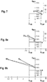
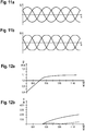
- An active module 65 is provided for further support. It acts on a pulse-wide modulation control element 34 of the grid-side inverter 33 in such a way that the modulation 33 carried out by the control element 34 takes place as overmodulation. Overmodulation of up to approx. 105% of the maximum output voltage in overvoltage range III (see Fig. 10 , upper diagram). The effect of overmodulation is in the Figures 11 and 12 shown. Based on the normal modulated case (i.e. without overmodulation), in Figure 11a the linked voltages in the three-phase three-phase system of the inverter 33 are shown. In Figure 11b is the case with Overmodulation shown.
- the active module 65 interacts with the active module 61 in such a way that it returns the active power to be output in the overvoltage range. In this way, the current available from the inverter 33 can be used more and more, even exclusively, to generate the reactive power required by the active module 65. This results in a synergistic interaction of the active modules 61, 63 and 64 in the overvoltage ranges.
- the active module 65 contains a modulation statics 65 '. It is designed such that it determines an overmodulation degree as a function of an overvoltage at the medium voltage U MW .
- the statics are designed as a proportional control element. In this a characteristic curve is implemented which has a gradient greater than 1, so that the control element is designed to be disproportionately large. This means that a quick response behavior can be achieved at the beginning of the critical overvoltage.
- an active module 66 is provided, which is designed as an additional activation module for the chopper 32.
- the chopper 32 is activated in the overvoltage range III.
- the active power is thus reduced compared to the grid, while the generator 2 can run through in the wind power installation and feed the power generated by it into the chopper. Relief of the generator 2 can thus be avoided.
- the module 66 preferably interacts with the active module 61, specifically in such a way that the chopper 32 is switched on by the active module 66 in particular when additional dynamic active power occurs in the overvoltage range. This is in Figure 6 visualized with the dashed lines in overvoltage area III.
- the mains transformer 8 is preferably designed such that magnetic saturation occurs above a predefined voltage-frequency combination. This has several advantages. On the one hand, the transformer 8 can be made smaller. With an intended operating frequency range of 45 Hz to 55 Hz, the transformer is expediently designed in such a way that saturation occurs at the lower end of the operating range (here 45 Hz) from an overvoltage of 116%. As a result of this saturation, the transformer generates additional reactive current, which is also favorable for protecting the system.
- the starting point is preferably selected such that the effect occurs primarily in the overvoltage ranges II and III.
- the limits for the overvoltage ranges should preferably be carried as a function of the network frequency f.
- a frequency adaptation element 77 is expediently provided for the overvoltage classifier 70.
Description
Windenergieanlage mit einem Windrotor, einem Generator, der von dem Windrotor angetrieben ist, und einem Umrichter zur Erzeugung elektrischer Energie, die über eine Anschlussleitung mit einer induktiv wirkenden Netzdrossel an ein Netz abgegeben wird, wobei ein Überspannungsschutzgerät vorgesehen ist.Wind energy plant with a wind rotor, a generator which is driven by the wind rotor, and a converter for generating electrical energy which is delivered to a network via a connecting line with an inductively acting line choke, an overvoltage protection device being provided.
Mit zunehmender Verbreitung von Windenergieanlagen werden auch erhöhte Anforderungen an ihr Verhalten am Netz gestellt. Dies gilt auch für das Verhalten der Windenergieanlage bei Netzstörungen, insbesondere dem Auftreten von Überspannungen oder Spannungsspitzen. Bisher haben die Windenergieanlagen häufig beim Auftreten von Spannungsspitzen aus Gründen des Eigenschutzes abgeschaltet. Jedoch wird ein solches Verhalten im Hinblick auf die Netzverträglichkeit künftig nicht mehr voll akzeptiert werden. Es wird bereits verlangt, dass Windenergieanlagen Überspannungen bis zu einem Wert von 130% der Nennspannung vertragen. Zukünftig sind zumindest in einigen Ländern auch verschärfte Anforderungen zu erwarten.With the increasing spread of wind turbines, there are also increased demands on their behavior on the grid. This also applies to the behavior of the wind turbine in the event of grid faults, in particular the occurrence of overvoltages or voltage peaks. So far, the wind turbines have often shut down when voltage peaks occur for reasons of self-protection. However, such behavior with regard to network compatibility will no longer be fully accepted in the future. It is already required that wind turbines tolerate overvoltages up to a value of 130% of the nominal voltage. In the future, stricter requirements can be expected, at least in some countries.
Herkömmliche Windenergieanlagen weisen keine ausreichenden Reserven für entsprechend erhöhte Anforderungen in Bezug auf die Überspannung auf. Zwar ist es grundsätzlich möglich, die stromführenden Komponenten und insbesondere den Umrichter leistungsmäßig höher auszulegen. Da hier aber Überleistungen von ca. 25% berücksichtigt werden müssen, führt dies zu erheblichen Steigerungen hinsichtlich Baugröße und Baukosten des Umrichters. Im Übrigen macht eine derartige Vergrößerung des Umrichters häufig eine neue Auslegung der Windenergieanlage und ihres elektrischen Systems insgesamt erforderlich. Der Aufwand steigt dadurch noch weiter an.Conventional wind turbines do not have sufficient reserves for correspondingly increased requirements with regard to overvoltage. In principle, it is possible to design the current-carrying components and in particular the converter to be higher in terms of performance. However, since over-performance of approx. 25% must be taken into account here, this leads to considerable increases in terms of size and construction costs of the converter. Incidentally, such an enlargement of the converter often requires a new design of the wind turbine and its electrical system as a whole. This increases the effort even further.
Aus
Aus der
Hingegen ist aus der
Der Erfindung liegt die Aufgabe zugrunde, eine verbesserte Überspannungsschutzeinrichtung bereitzustellen, welche höhere Überspannungsfestigkeiten auf effizientere Weise erreicht.The object of the invention is to provide an improved overvoltage protection device which achieves higher overvoltage strengths in a more efficient manner.
Diese Aufgabe wird erfindungsgemäß durch eine Windenergieanlage nach Anspruch 1 gelöst.This object is achieved according to the invention by a wind turbine according to
Bei einer Windenergieanlage mit einem Windrotor, einem Generator, der von dem Windrotor angetrieben ist, und einem Umrichter, wobei der Generator und der Umrichter zur Erzeugung elektrischer Energie ausgebildet sind, die über eine Anschlussleitung mit einer induktiv wirkenden Netzdrossel an ein Netz abgegeben wird, wobei ein Überspannungsschutzgerät vorgesehen ist, ist erfindungsgemäß das Überspannungsschutzgerät so ausgebildet, dass es mehrere unterschiedliche Wirkmodule umfasst, die so ausgebildet sind, dass sie auf voneinander verschiedene Weise jeweils eine Senkung der Spannung am Ausgang des Umrichters bewirken, wobei sich die Wirkmodule hinsichtlich ihrer Funktionsweise unterscheiden, eine Schaltmatrix, welche die unterschiedlichen Wirkmodule im Überspannungsbereich zu- und abschaltet, ein Überspannungsklassifikator zur Erfassung der Spannung an der Anschlussleitung, wobei der Überspannungsklassifikator ausgebildet ist, die erfasste Spannung einem von mehreren Überspannungsbereichen zuzuordnen, und einen Selektor, der dazu ausgebildet ist, je nach Überspannungsbereich Schaltgruppen anzusteuern, welche Schaltgruppen ausgebildet sind, entsprechende Zu- und Abschaltsignale über die Schaltmatrix an die Wirkmodule auszugeben um festzulegen, welche Wirkmodule in welchem Überspannungsbereich aktiviert bzw. deaktiviert sind.In a wind power plant with a wind rotor, a generator which is driven by the wind rotor, and a converter, the generator and the converter being designed to generate electrical energy which is delivered to a network via a connecting line with an inductively acting line choke, wherein an overvoltage protection device is provided, the overvoltage protection device is designed according to the invention in such a way that it comprises a number of different active modules which are designed in such a way that they each lower the voltage at the output of the converter in different ways, the active modules differing in their mode of operation, a switching matrix which switches the different active modules on and off in the overvoltage range, an overvoltage classifier for detecting the voltage on the connecting line, the overvoltage classifier being designed, the detected voltage being one of several overvoltage ranges hen to assign, and a selector, which is designed to control switching groups depending on the overvoltage range, which switching groups are designed to output corresponding activation and deactivation signals via the switching matrix to the active modules in order to determine which active modules are activated or deactivated in which overvoltage range.
Unter Überspannungsbereichen werden Spannungsbereiche oberhalb der Nennspannung verstanden, die sich über jeweils vorab bestimmte Abschnitte erstrecken. So kann beispielsweise ein erster Überspannungsbereich zwischen 116 und 130% der Netzspannung liegen, ein zweiter Überspannungsbereich zwischen 130 und 145%, und schließlich ein dritter Überspannungsbereich zwischen 145 und 170%.Overvoltage ranges are understood to mean voltage ranges above the nominal voltage that are in each case extend certain sections in advance. For example, a first overvoltage range can lie between 116 and 130% of the mains voltage, a second overvoltage range between 130 and 145%, and finally a third overvoltage range between 145 and 170%.
Unter Wirkmodule werden solche Baueinheiten verstanden, die jeweils für sich genommen eine Erhöhung der Überspannungsfestigkeit der Windenergieanlage selbst bewirken.Active modules are understood to mean those structural units which, taken on their own, bring about an increase in the surge resistance of the wind energy installation itself.
Die Erfindung ermöglicht durch die selektive Schaltung verschiedener Wirkmodule, dass verschiedene Ansätze zur Erhöhung der Überspannungsfestigkeit miteinander kombiniert werden. Dadurch tritt ein kombinatorischer Effekt auf, der es ermöglicht, auch erhöhte Anforderungen an die Überspannungsfestigkeit bei Spannungsspitzen, bis hin zu beispielsweise 170% der Netzspannung, auf dieser Basis zu bewältigen, ohne dass dazu eine leistungsmäßige höhere Auslegung des Umrichters erforderlich wäre. Es können also die bisher verwendeten Umrichter weiter verwendet werden. Dadurch wird erheblicher Aufwand eingespart. Die Erfindung erreicht dies durch das innovative Zusammenwirken verschiedener, teilweise an sich bekannter Maßnahmen. Im Stand der Technik findet sich hierfür kein Beispiel.The selective switching of different active modules enables the invention to combine different approaches to increase the surge resistance. This results in a combinatorial effect, which makes it possible to cope with increased requirements for surge resistance during voltage peaks, up to, for example, 170% of the line voltage, without the need for a higher power rating of the converter. The inverters previously used can therefore continue to be used. This saves considerable effort. The invention achieves this through the innovative interaction of various measures, some of which are known per se. There is no example of this in the prior art.
Die Erfindung erreicht damit nicht nur eine hohe Überspannungstoleranz, sondern ermöglicht es, die wesentlichen Kernkomponenten der Windenergieanlage, insbesondere deren Umrichter, unverändert zu belassen. Weiter erlaubt sie eine abgestufte Reaktion je nach Schwere der Überspannungssituation (Überspannungsbereich). Überdies ist das Verhalten der Windenergieanlage gegenüber dem Netz transparent, d.h. aus Sicht des Netzes verhält sich die Windenergieanlage vollkommen unauffällig, so als ob sie die geforderte Spannungsfestigkeit aufgrund eines höher ausgelegten Umrichters aufweist. Insgesamt ergibt sich somit ein viel effektiverer Schutz der Windenergieanlage vor Überspannungen, verglichen mit den bisher entweder nicht ausreichenden Maßnahmen oder ausgesprochen teuren Maßnahmen, wie einer erheblichen Überauslegung des Umrichters.The invention thus not only achieves a high overvoltage tolerance, but also makes it possible to leave the essential core components of the wind energy installation, in particular its converter, unchanged. It also allows one graded response depending on the severity of the overvoltage situation (overvoltage range). In addition, the behavior of the wind energy installation with respect to the network is transparent, ie from the network perspective, the wind energy installation behaves completely inconspicuously, as if it had the required dielectric strength due to a higher-level converter. Overall, this results in a much more effective protection of the wind energy installation against overvoltages, compared to the measures which have hitherto either not been sufficient or extremely expensive measures, such as a considerable over-design of the converter.
Vorzugsweise ist der Selektor so ausgebildet, dass mindestens zwei, vorzugsweise drei verschiedene Überspannungsstufen schaltbar sind. Damit kann als erster Überspannungsbereich der bereits bisher verwendete Überspannungsbereich von 116% (Ende des Toleranzbands um die Nennspannung) bis hin zu 130% vorgesehen sein. Daran schließt sich an ein erweiterter Überspannungsbereich von 130% bis 145%. An diese wiederum schließt sich ein Überlebensbereich an, in dem der Eigenschutz der Windenergieanlage Vorrang hat, bis etwa 170%. Damit sind die Anforderungen praktisch aller relevanten Länder abgedeckt und es wird auch eine ausreichende Eigensicherung der Windenergieanlage erreicht, bei nach wie vor minimalem Zusatzaufwand. Zweckmäßigerweise sind der Selektor und die Schaltmatrix kombiniert ausgeführt. Dies ermöglicht eine besonders kompakte Bauweise. Ein Beispiel hierfür ist eine Ausführung als ein Stufenschalter.The selector is preferably designed such that at least two, preferably three, different overvoltage stages can be switched. Thus, the overvoltage range from 116% (end of the tolerance band around the nominal voltage) up to 130% can be provided as the first overvoltage range. This is followed by an extended overvoltage range from 130% to 145%. This in turn is followed by a survival area in which the self-protection of the wind turbine has priority, up to around 170%. This covers the requirements of practically all relevant countries and also ensures that the wind turbine is adequately protected, with minimal additional effort. The selector and the switching matrix are expediently combined. This enables a particularly compact design. An example of this is a version as a tap changer.
Mit Vorteil ist eines der Wirkmodule ausgebildet als ein Reduktionsglied zur Reduktion der abgegebenen Wirkleistung der Windenergieanlage, und zwar erst ab mindestens einem zweiten Überspannungsbereich. Damit wird erreicht, dass bei höheren Überspannungen (im erweiterten Überspannungsbereich oder gar erst im Überlebensbereich) die von der Windenergieanlage abgegebene Wirkleistung reduziert wird. Der so von der Abgabe von Wirkleistung entlastete Umrichter kann dann entsprechend mehr Blindleistung abgeben. Vorzugsweise erfolgt dies graduell. Dazu ist zweckmäßigerweise eine Stromstatik implementiert, wobei der abgegebene Wirkstrom mit steigender Spannung zunehmend reduziert wird.One of the active modules is advantageously designed as a reduction element for reducing the active power output of the wind energy installation, and only from at least a second overvoltage range. This ensures that at higher overvoltages (in the extended overvoltage range or even in the survival range) the active power delivered by the wind turbine is reduced. The converter, which is relieved of the output of active power in this way, can then output correspondingly more reactive power. This is preferably done gradually. Current statics are expediently implemented for this purpose, the active current emitted being increasingly reduced with increasing voltage.
Ein anderes der Wirkmodule ist vorzugsweise dazu ausgebildet, als ein veränderlicher Limiter für eine kapazitive Blindleistungsabgabe zu fungieren. Unter einem veränderlichen Limiter wird hier verstanden, dass je nach Überspannungsbereich eine zulässige Obergrenze für die kapazitive Blindleistungsabgabe definiert und mit zunehmend steigender Spannung abgesenkt wird. Vorzugsweise weist der Limiter hierzu eine Begrenzungsstatik auf. Damit kann beim Auftreten von Überspannung die Abgabe kapazitiver Blindleistung bis auf null (oder einen anderen einstellbaren Unterwert) abgesenkt werden. Mit dieser Maßnahme wird spannungssenkend auf den netzseitigen Wechselrichter eingewirkt.Another of the active modules is preferably designed to act as a variable limiter for a capacitive reactive power output. A variable limiter is understood here to mean that, depending on the overvoltage range, an allowable upper limit for the capacitive reactive power output is defined and is lowered with increasing voltage. For this purpose, the limiter preferably has a limiting statics. This means that when overvoltage occurs, the output of capacitive reactive power can be reduced to zero (or another adjustable lower value). This measure has a voltage-reducing effect on the grid-side inverter.
Mit Vorteil weist ein anderes der Wirkmodule eine Überstromsteuerung auf, welche eine erhöhte induktive Blindleistungsabgabe einstellt, die vorzugsweise über der Nenn-Blindleistungsabgabe liegt. Damit macht sich das Wirkmodul die Erkenntnis zunutze, dass durch die Abgabe von induktiver Blindleistung eine Spannungssenkung erreicht werden kann. Der damit erreichte Umfang hängt ab von der Dimensionierung der Drossel und des Transformators in der Anschlussleitung. Vorzugsweise ist die Drossel so bemessen, dass der Stromfluss durch sie am oberen Ende des erweiterten Überspannungsbereichs maximal das 1,6-fache, vorzugsweise höchstens des 1,1-fachen des Nennstroms des netzseitigen Wechselrichters beträgt. Hierbei kann in einer zweiten Stufe für den Überlebensspannungsbereich die erhöhte induktive Blindleistung so dimensioniert sein, dass sie mindestens das Doppelte, vorzugsweise mindestens das Vierfache, der Nenn-Blindleistungsabgabe beträgt.Another of the active modules advantageously has an overcurrent control which sets an increased inductive reactive power output, which is preferably above the nominal reactive power output. The active module thus takes advantage of the knowledge that a voltage reduction can be achieved by delivering reactive inductive power. The extent achieved depends on the dimensioning of the choke and the transformer in the connection line. The choke is preferably dimensioned such that the current flow through it at the upper end of the expanded Overvoltage range is a maximum of 1.6 times, preferably at most 1.1 times the rated current of the grid-side inverter. In this case, in a second stage for the survival voltage range, the increased inductive reactive power can be dimensioned such that it is at least twice, preferably at least four times, the nominal reactive power output.
Eines der Wirkmodule ist vorzugsweise als eine Spannungsstatik für einen Sollspannungsschieber in einem Zwischenkreis des Umrichters ausgebildet. Damit kann der Selektor im gewünschten Überspannungsbereich die Zwischenkreisspannung im Umrichter planvoll anheben. Vorzugsweise erfolgt die Anhebung überproportional, d.h. wenn die Anhebung erfolgt, dann erfolgt sie im größeren Umfang als die Steigerung der Netzspannung. Durch die Anhebung der Zwischenkreisspannung wird erreicht, dass die von dem netzseitigen Wechselrichter des Umrichters an das Netz abgegebene Spannung ebenfalls ansteigen kann. Die Windenergieanlage kann sich somit an die erhöhte Spannung im Netz anpassen.One of the active modules is preferably designed as a voltage statics for a target voltage slide in an intermediate circuit of the converter. This allows the selector to raise the DC link voltage in the converter in the desired overvoltage range. The increase is preferably disproportionate, i.e. if the increase takes place, then it takes place to a greater extent than the increase in the mains voltage. By increasing the intermediate circuit voltage, it is achieved that the voltage delivered to the grid by the converter's grid-side inverter can also rise. The wind turbine can thus adapt to the increased voltage in the network.
Vorzugsweise ist eines der Wirkmodule ausgebildet als ein Übermodulationsglied, welches die vom Umrichter, genauer gesagt dessen netzseitigen Wechselrichter, abgegebene Spannung erhöht. Mit dem Übermodulationsglied kann insbesondere in hohen Spannungsbereichen (Überlebensbereiche) durch kurzzeitige Übermodulation die Ausgangsspannung des netzseitigen Wechselrichters weiter erhöht und damit an die erhöhte Netzspannung angepasst werden. Bewährt haben sich hierfür Übermodulationsgrade, die mindestens 5%, vorzugsweise bis zu 7% Spannungsanhebung bewirken können. So wird einerseits eine beträchtliche Anhebung der Ausgangsspannung erreicht, und andererseits eine übermäßige Erhöhung des Klirrfaktors und damit eine übermäßige Strombelastung noch verhindert. Vorzugsweise ist der Klirrfaktor auf einen Wert von höchstens 20% eingestellt.One of the active modules is preferably designed as an overmodulation element which increases the voltage output by the converter, more precisely its grid-side inverter. With the overmodulation element, especially in high voltage ranges (survival ranges), the output voltage of the grid-side inverter can be further increased by short-term overmodulation and thus be adapted to the increased grid voltage. Overmodulation levels that can bring about at least 5%, preferably up to 7% voltage boost, have proven effective for this. On the one hand, a considerable increase in the output voltage is achieved, and on the other hand an excessive increase in the Distortion factor and thus an excessive current load is still prevented. The distortion factor is preferably set to a value of at most 20%.
Zur Steuerung des Übermodulationsglieds ist vorzugsweise eine Spannungsstatik vorgesehen. Sie ist zweckmäßigerweise in mehrere Bereiche unterteilt. Damit kann je nach Überspannungsbereich ein unterschiedliches Verhalten festgelegt sein. Mit Vorteil erfolgt dies bereits im ersten Überspannungsbereich, und zwar in einem überproportionalen Umfang. Dazu ist eine Kennliniensteigung größer als eins (überproportional) in der Spannungsstatik implementiert. Vorzugsweise ist sie Teil einer Rampenfunktion, welche in einem anderen Überspannungsbereich einen dann erhöhten konstanten Wert aufweist.Voltage control is preferably provided to control the overmodulation element. It is expediently divided into several areas. Depending on the overvoltage range, this can result in different behavior. This advantageously takes place in the first overvoltage range, to a disproportionate extent. For this purpose, a slope of the characteristic greater than one (disproportionately) is implemented in the stress statics. It is preferably part of a ramp function which then has an increased constant value in another overvoltage range.
Zweckmäßigerweise weist das Reduktionsglied ferner einen Steuerausgang zur Aktivierung eines Choppers am Zwischenkreis auf. Die Aktivierung kann direkt oder indirekt erfolgen. Unter "indirekt" wird verstanden, dass das Reduktionsglied den Chopper nicht direkt aktiviert, sondern Schaltschwellen bzw. Grenzwerte der an sich vorhandenen Choppersteuerung modifiziert werden und damit dessen Einsatzverhalten in gewünschter Weise verändert wird. Damit kann das Reduktionsglied zusätzlich auch zumindest kurzfristig Leistung in den Chopper abführen, um so den Zwischenkreis zu entlasten. Die Strombelastung des netzseitigen Wechselrichters wird so weiter verringert bzw. er kann entsprechend mehr Blindstrom und damit Blindleistung abgeben.The reduction element expediently also has a control output for activating a chopper on the intermediate circuit. Activation can be direct or indirect. “Indirectly” means that the reduction element does not directly activate the chopper, but rather switching thresholds or limit values of the chopper control which is present per se are modified and thus its usage behavior is changed in the desired manner. In this way, the reducing element can also dissipate power into the chopper, at least for a short time, in order to relieve the intermediate circuit. The current load on the grid-side inverter is thus further reduced or it can correspondingly emit more reactive current and thus reactive power.
Weiter kann vorgesehen sein, dass vorzugsweise bei einer Netzfrequenz unterhalb einer Nenn-Netzfrequenz eine Maximalspannung verringert wird. Damit ist eine günstigere magnetische Auslegung des Transformators der Windenergieanlage ermöglicht. Weiter ist vorzugsweise ein Zusammenwirken mit dem Überspannungsklassifikator in der Weise vorgesehen, dass bei abgesenkter Maximalspannung die Klassifikation mit entsprechend verringerten Werten erfolgt. Damit wird die Klassifikation nachgeführt in Bezug auf die verringerte Maximalspannung, und so weiterhin eine feinfühlig abgestufte Reaktion sichergestellt.It can further be provided that a maximum voltage is preferably at a network frequency below a nominal network frequency is reduced. This enables a more favorable magnetic design of the transformer of the wind turbine. Furthermore, an interaction with the overvoltage classifier is preferably provided in such a way that the classification is carried out with correspondingly reduced values when the maximum voltage is reduced. In this way, the classification is tracked in relation to the reduced maximum voltage, thus ensuring a sensitive, graded reaction.
Vorzugsweise ist der Anlagentransformator in der Anschlussleitung der Windenergieanlage so bemessen, dass er bei Netzfrequenzen unterhalb einer Nenn-Netzfrequenz magnetisch gesättigt ist im Überspannungsbereich. Mit einem so derart ausgelegten Transformator wird erreicht, dass er sich beim Auftreten von Überspannungen durch zusätzlichen Sättigungsstrom wie eine induktive Drossel verhält, und damit automatisch sozusagen passiv-spannungssenkend wirkt. Der Transformator greift damit selbsttätig stabilisierend ein. Wegen seiner erheblichen Induktivität wird damit ohne Zusatzaufwand ein beträchtlicher Beitrag zur Spannungssenkung erzielt. Ein gewisser Nachteil besteht zwar darin, dass der Ansetzpunkt für seine spannungssenkende Wirkung wegen der Frequenzabhängigkeit nicht ganz genau festzulegen ist, jedoch ist dies im Hinblick auf die damit erreichten Vorteile nicht gravierend.The installation transformer in the connection line of the wind energy installation is preferably dimensioned such that it is magnetically saturated in the overvoltage range at line frequencies below a nominal line frequency. A transformer designed in this way ensures that it behaves like an inductive choke when overvoltages occur due to additional saturation current, and thus automatically has a passive voltage-reducing effect, so to speak. The transformer thus intervenes to stabilize itself. Because of its considerable inductance, it makes a significant contribution to reducing the voltage without additional effort. A certain disadvantage is that the starting point for its voltage-lowering effect cannot be determined exactly because of the frequency dependence, but this is not serious in view of the advantages achieved thereby.
Weiter vorzugsweise ist der Anlagentransformator ausgelegt für eine abgesenkte Hauptfeldspannung. Damit kann der Anlagentransformator kleiner dimensioniert sein, so dass er letztlich sogar kostengünstiger ist.The plant transformer is further preferably designed for a lowered main field voltage. The system transformer can thus be dimensioned smaller, so that it is ultimately even more cost-effective.
Die Erfindung wird nachfolgend unter Bezugnahme auf die beigefügte Zeichnung näher erläutert, in der ein vorteilhaftes Ausführungsbeispiel dargestellt ist. Es zeigen:
- Fig. 1
- ein Windpark in einer Übersichtsdarstellung mit einer Windenergieanlage gemäß einem Ausführungsbeispiel der Erfindung;
- Fig. 2
- ein Blockschaltbild zu der Windenergieanlage;
- Fig. 3
- eine Detailansicht zu einem Selektor mit einem Überspannungsklassifikator;
- Fig. 4
- ein Beispiel für Überspannungsbereiche;
- Fig. 5
- Schaltstufen des Selektors für Wirkmodule;
- Fig. 6a, b
- Diagramm zu einem Wirkmodul zur Wirkleistungsreduktion;
- Fig. 7
- Diagramme zu einem Limiter für kapazitive Blindleistung;
- Fig. 8a, b
- Diagramme zu einem Wirkmodul zur Zusatzblindleistungseinspeisung;
- Fig. 9
- Diagramme zu einem Wirkmodul für eine Anhebung der Zwischenkreisspannung und der Ausgangsspannung eines netzseitigen Wechselrichters;
- Fig. 10a, b
- Diagramme zum Wirkmodul für eine Übermodulation;
- Fig. 11a, b
- Diagramme zu wirksamen Spannungsverläufen ohne und mit Übermodulation;
- Fig. 12a, b
- Diagramme zu einer vom Umrichter ans Netz abgegebenen wirksamen Spannung und zu Stromoberschwingungen;
- Fig. 13a-c
- Diagramme zur Auslegung einer Netzdrossel; und
- Fig. 14a, b
- Diagramme zum Netzstrom und zum von der Windenergieanlage abgegebenen Strom für die Überspannungsbereiche.
- Fig. 1
- a wind farm in an overview with a wind turbine according to an embodiment of the invention;
- Fig. 2
- a block diagram of the wind turbine;
- Fig. 3
- a detailed view of a selector with an overvoltage classifier;
- Fig. 4
- an example of overvoltage ranges;
- Fig. 5
- Switching stages of the selector for active modules;
- 6a, b
- Diagram of an active module for active power reduction;
- Fig. 7
- Diagrams for a limiter for capacitive reactive power;
- 8a, b
- Diagrams of an active module for additional reactive power feed-in;
- Fig. 9
- Diagrams of an active module for raising the intermediate circuit voltage and the output voltage of a grid-side inverter;
- 10a, b
- Diagrams of the active module for overmodulation;
- 11a, b
- Diagrams of effective voltage curves with and without overmodulation;
- Figures 12a, b
- Diagrams of an effective voltage delivered by the converter to the grid and current harmonics;
- Figures 13a-c
- Diagrams for designing a line reactor; and
- 14a, b
- Diagrams of the grid current and the current delivered by the wind turbine for the overvoltage ranges.
Ein in dem Ausführungsbeispiel gemäß
Die Windenergieanlage 1 gemäß dem Ausführungsbeispiel der Erfindung umfasst einen Turm 10, auf dessen oberem Ende in Azimutrichtung schwenkbeweglich eine Gondel 11 angeordnet ist. An deren einer Stirnseite ist drehbeweglich ein Windrotor 12 gelagert, der über eine Rotorwelle (nicht dargestellt) einen Generator 2 zur Erzeugung elektrischer Energie antreibt. Dieser ist mit einem Umrichter 3 verbunden zur Abgabe der erzeugten elektrischen Energie über eine Niederspannungsanschlussleitung 18, die an den Anlagentransformator 8 angeschlossen ist und eine Netzdrossel 4 umfasst. Die Netzdrossel 4 ist vorzugsweise als ein LCL-Filter ausgeführt.The
In dem Blockschaltbild gemäß
Die Netzdrossel 4 ist als ein LCL-Netzfilter ausgeführt und umfasst zwei Induktivitäten, eine umrichterseitige Induktivität 41 und eine netzseitige Induktivität 42. Zwischen ihnen ist ein Siebkondensator 43 angeschlossen. Am Ausgang der Netzdrossel 4 ist ein Niederspannungstrennschalter 40 angeordnet. Der über ihn in geschlossenem Zustand fließende Strom wird als ILSI bezeichnet. Netzseitig hiervor ist ein Anschlusspunkt 44 vorgesehen, der zur Versorgung der elektrischen Komponenten der Windenergieanlage 1 einschließlich ihrer Steuerung 14 dient (der sog. Eigenbedarf). Netzseitig von diesem Anschlusspunkt 44 ist der Maschinentransformator 8 der Windenergieanlage 1 angeschlossen. Der zwischen dem Anschlusspunkt 44 für den Eigenbedarf und dem Maschinentransformator 8 durch eine Niederspannungsanschlussleitung 18 fließende Strom wird als ILV bezeichnet, und die dort herrschende Spannung als ULV. Es handelt sich hierbei um die Spannung an der Niederspannungsseite des Maschinentransformators 8. An dessen Mittelspannungsseite ist ein Mittelspannungsschalter 80 angeordnet, von dem die Anschlussleitung 19 an das parkinterne Sammelnetz 90 führt. Der durch die Anschlussleitung 19 fließende Strom wird als IMV und die dort herrschende Spannung als ÜMV bezeichnet.The
Die Steuerung 14 der Windenergieanlage umfasst ein Überspannungsschutzgerät 5, welches dazu dient, die Windenergieanlage 1 bei Spannungsstörungen im Netz, insbesondere beim Auftreten von Überspannungen, vor schädlich hohen Spannungen und deren negativen Auswirkungen zu schützen.The
Das Überspannungsschutzgerät 5 gemäß dem Ausführungsbeispiel der Erfindung umfasst mehrere Wirkmodule 61, 62, 63, 64, 65, 66 welche auf jeweils unterschiedliche Weise zu einer Reduktion eines Spannungsanstiegs beitragen. Die Wirkmodule 61-66 sind dazu ausgebildet, dass bei einem netzseitigen Anstieg der Mittelspannung UMV, und entsprechend auch der in der Niederspannungsanschlussleitung 18 anliegenden Spannung ULV, sich ein geringer Spannungsanstieg im Bereich des Umrichters 3 der Windenergieanlage einstellt, so dass dieser vor zu hohen Spannungen geschützt ist. Maßgeblich ist hier für die Spannung am Ausgang des Wechselrichters 33, mithin also ULSI.The
Das Überspannungsschutzgerät 5 umfasst eine Schaltmatrix 6, mit welcher die Wirkmodule 61-66 verknüpft sind. Die Schaltmatrix 6 schaltet je nach Schaltzustand die unterschiedlichen Wirkmodule zu oder ab. Hierzu ist außer der Schaltmatrix 6 ein Selektor 7 mit einem Überspannungsklassifikator 70 vorgesehen. Der Überspannungsklassifikator 70 ist angeschlossen an einen Spannungssensor 17, welcher die Spannung in der Anschlussleitung 19 der Windenergieanlage 1 misst (eine Messung an der Niederspannungsanschlussleitung 18 ist auch möglich). An dem Überspannungsklassifikator sind Werte für Überspannungsbereiche I, II, III eingestellt. Der Überspannungsklassifikator ist dazu ausgebildet, je nach der von dem Sensor 17 gemessenen Spannung zu bestimmen, ob eine Überspannung vorliegt, also eine Spannung oberhalb der Nennspannung des Netzes plus ein vorbestimmter Toleranzbereich. Die nachfolgenden Werte beziehen sich auf die Mittelspannung (bei einem alternativ möglichen Bezug auf die Niederspannung wären die prozentualen Grenzwerte geringfügig abweichend). Vorliegend soll es sich bei dem vorbestimmten Toleranzbereich um einen Wert von bis +16% der Netzspannung handeln. Mithin beginnt also ab einem Wert von 116% der Nennspannung die Überspannung. Der Überspannungsklassifikator 70 bestimmt nun je nachdem, ob die Netzspannung zwischen 116 und 130% der Nennspannung, zwischen 130 und 145% der Nennspannung, oder zwischen 145 und 170% der Nennspannung liegt, welche Stufe des Selektors 7 er ansteuert. Der Selektor 7 steuert nun je nachdem, welche seiner Stufen von dem Überspannungsklassifikator 70 angesteuert wurden, Schaltgruppen 71, 72, 73 an, welche entsprechende Zu- oder Abschaltsignale über die Schaltmatrix 6 an die Wirkmodule 61-66 ausgeben. Somit kann über den Selektor 7 und die Schaltmatrix 6 festgelegt werden, welche der Wirkmodule in welchem Überspannungsbereich aktiviert bzw. deaktiviert sind. Dies kann über die Schaltmatrix 6 frei eingestellt werden. Hierbei sei es so, dass in einem ersten Überspannungsbereich (zwischen 116% und 130% der Nennspannung) die Schaltgruppe 71 angesteuert ist. Dieser Fall wird nachfolgend als Überspannungsbereich I bezeichnet. Für den Fall einer Überspannung im Bereich zwischen 130 und 145% ist die Schaltgruppe 72 betätigt, dieser Fall wird als Überspannungsbereich II bezeichnet. Liegt die Spannung im Bereich zwischen 145% und 170%, ist die Schaltgruppe 73 betätigt und dieser Fall wird als Überspannungsbereich III bezeichnet. Die Überspannungsbereiche sind in
Nachfolgend werden die Wirkmodule hinsichtlich ihres Aufbaus und ihrer Funktionsweise sowie ihrer Auswirkung auf die elektrischen Parameter, insbesondere die Spannung und Ströme, näher beschrieben.The active modules are described in more detail below with regard to their structure and mode of operation and their effect on the electrical parameters, in particular the voltage and currents.
Das Wirkmodul 61 ist als ein Reduktionsglied ausgeführt und dazu ausgebildet, bei kritischer Überspannung (also im Überspannungsbereich III) die von dem Umrichter 3 abgegebene Wirkleistung zu reduzieren. Dazu ist in dem Wirkmodul 61 eine Spannungsstatik 61' implementiert, welche als eine negative Proportionalsteuerung ausgebildet ist. Das bedeutet, dass oberhalb eines einstellbaren Schwellwerts die von dem Umrichter 3 abgegebene Wirkleistung mit steigender Spannung reduziert wird. Hierbei kommt es auf die Spannung der Mittelspannungsebene UMV an. Die Proportionalsteuerung in der Spannungsstatik 61' ist so eingestellt, dass beim Erreichen des oberen Endes des Überspannungsbereichs III bei einem Wert von 170% der Nennspannung die Wirkleistungseinspeisung auf null reduziert ist (s. Punkt X in
Das Wirkmodul 62 ist als Limiter ausgeführt und dazu ausgebildet, derart auf den netzseitigen Wechselrichter 33 des Umrichters 3 zu wirken, dass dessen übererregte Blindleistung im Überspannungsbereich I mit zunehmender Netzspannung auf null reduziert wird. Bezugspunkt ist wiederum die Mittelspannung ÜMV. Dazu ist in dem Wirkmodul 62 eine entsprechende Blindleistungsstatik 62' implementiert. Veranschaulicht ist dies in
Das Wirkmodul 62 ist in Überspannungsbereichen II und III vorzugsweise nicht mehr aktiv, da die Einspeisung übererregter Blindleistung dann ohnehin bereits den Wert Null erreicht hat (s. Punkt B in
Ferner ist ein Wirkmodul 63 als eine induktive Überstromsteuerung vorgesehen, welches ebenfalls auf die Blindleistung einwirkt. Es ist zum Zusammenwirken mit dem Limiter des Wirkmoduls 62 in der Weise ausgebildet, dass das Wirkmodul 63 erst dann zum Einsatz kommt, wenn das Wirkmodul 62 die Abgabe übererregter Blindleistung auf den Wert Null reduziert hat. Das Wirkmodul 63 weist zwei Blindleistungsstatiken 63', 63" auf, eine für den Überspannungsbereich II und eine weitere für den Überspannungsbereich III. Es wird Bezug genommen auf die
Im Überspannungsbereich III schaltet das Wirkmodul 63 auf die Spannungsstatik 63" um. Es wird Bezug genommen auf Figur 8b. Für den Fall einer großen Netzdrossel 4 ist die Blindleistungsstatik 63" so ausgelegt, dass beim Erreichen des oberen Endes des Überspannungsbereichs III (bei UMV = 170% des Nennwerts) eine untererregte Blindleistung von etwa dem 2,5-fachen des Nennwerts erreicht ist (s. Abszissenwert -2,5 für QIND), visualisiert durch den Punkt D in
Um dem Wechselrichter 33 die Bereitstellung der teilweise sehr hohen Leistungsanforderungen, wie vorstehend beschrieben, zu ermöglichen, ist das Wirkmodul 64 vorgesehen. Es wirkt auf die Spannung im Zwischenkreis 31 des Umrichters 3 ein. Das Wirkmodul 64 weist einen Sollspannungsschieber auf, der auf ein Steuerungsglied 36 für die Spannung im Zwischenkreis einwirkt. Es ist dazu ausgebildet, beim Erreichen des Überspannungsbereichs I den Sollwert für die Spannung im Zwischenkreis zu einem höheren Wert zu verschieben, im dargestellten Ausführungsbeispiel von einem normalen Wert für die Spannung im Zwischenkreis von 1100 V auf einen erhöhten Spannungswert von 1150 V (s.
Durch die Steigerung der Spannung im Zwischenkreis kann die von dem netzseitigen Wechselrichter 33 abgegebene Spannung ULSI entsprechend erhöht werden. Die hierbei erreichte Steigerung bildet diejenige im Zwischenkreis 31 ab. Die somit erreichte Steigerung der Spannung ULSI ist in
Zur weiteren Unterstützung ist ein Wirkmodul 65 vorgesehen. Es wirkt auf ein pulsweites Modulations-Steuerglied 34 des netzseitigen Wechselrichters 33 ein, und zwar in der Weise, dass die von dem Steuerglied 34 durchgeführte Modulation 33 als Übermodulation erfolgt. Vorgesehen ist eine Übermodulation bis zu ca. 105% der Ausgangsmaximalspannung im Überspannungsbereich III (s.
Der erwünschte Anstieg des Effektivwerts der abgegebenen Spannung ist in
Ferner wirkt das Wirkmodul 65 mit dem Wirkmodul 61 in der Weise zusammen, indem dieses die abzugebende Wirkleistung im Überspannungsbereich zurückführt. Auf diese Weise kann der vom Wechselrichter 33 verfügbare Strom zusehends mehr, bis hin zu ausschließlich, für die Erzeugung der von dem Wirkmodul 65 benötigten Blindleistung verwendet werden. Damit ergibt sich ein synergistisches Zusammenwirken der Wirkmodule 61, 63 und 64 in den Überspannungsbereichen.Furthermore, the
Das Wirkmodul 65 enthält eine Modulationsstatik 65'. Sie ist so ausgebildet, dass sie in Abhängigkeit von einer Überspannung an der Mittelspannung UMW einen Übermodulationsgrad bestimmt. Hierbei ist die Statik als ein Proportionalsteuerglied ausgebildet. In diesem ist eine Kennlinie implementiert, die eine Steigung größer als 1 aufweist, so dass das Steuerglied überproportional ausgelegt ist. Damit kann ein schnelles Ansprechverhalten bereits zu Beginn der kritischen Überspannung erreicht werden.The
Weiter ist ein Wirkmodul 66 vorgesehen, welches als ein Zusatzaktivierungsmodul für den Chopper 32 ausgeführt ist. Hierbei wird der Chopper 32 im Überspannungsbereich III aktiviert. Damit wird die Wirkleistung gegenüber dem Netz reduziert, während der Generator 2 in der Windenergieanlage durchlaufen kann und die von ihm erzeugte Leistung in den Chopper einspeist. Damit kann eine Entlastung des Generators 2 vermieden werden. Vorzugsweise wirkt das Modul 66 mit dem Wirkmodul 61 zusammen, und zwar in der Weise, dass insbesondere beim Auftreten zusätzlicher dynamischer Wirkleistung im Überspannungsbereich der Chopper 32 durch das Wirkmodul 66 hinzugeschaltet wird. Dies ist in
In den Diagrammen in
Die sich ergebenden Ströme auf der Niederspannungsseite des Netztransformators 8 (Strom ILV) über der Mittelspannung UMV sind in
Der Netztransformator 8 ist vorzugsweise so ausgelegt, dass oberhalb einer vordefinierten Spannungs-Frequenzkombination eine magnetische Sättigung eintritt. Dadurch werden mehrere Vorteile erzielt. Zum einen kann der Transformator 8 kleiner ausgelegt werden. Bei einem vorgesehenen Betriebs-Frequenzbereich 45 Hz bis 55 Hz ist der Transformator zweckmäßigerweise so ausgelegt, dass am unteren Ende des Betriebsbereichs (hier 45 Hz) eine Sättigung eintritt ab einer Überspannung von 116 %. Durch diese Sättigung erzeugt der Transformator zusätzlichen Blindstrom, der weiter für den Schutz der Anlage günstig ist. Vorzugsweise ist der Einsetzpunkt so gewählt, dass die Wirkung primär in den Überspannungsbereichen II und III auftritt.The
Da dieser Effekt frequenzabhängig ist, sind vorzugsweise die Grenzen für die Überspannungsbereiche in Abhängigkeit von der Netzfrequenz f mitzuführen. Dazu ist zweckmäßigerweise ein Frequenz-Adaptionsglied 77 für den Überspannungsklassifikator 70 vorgesehen.Since this effect is frequency-dependent, the limits for the overvoltage ranges should preferably be carried as a function of the network frequency f. For this purpose, a
Claims (20)
- Wind turbine comprising a wind rotor (12), a generator (2) which is driven by the wind rotor (12), and a converter (3), wherein the generator (2) and the converter (3) are designed to generate electrical energy, which is output via a connecting line (19) with an inductively acting line reactor (4) to a grid (90), wherein an overvoltage protection device (5) is provided,
characterized in that
the overvoltage protection device comprises- a plurality of different active modules (61-66), which are designed in such a way that they each effect, in different ways, a reduction in the voltage at the output of the converter (3), wherein the active modules (61-66) differ in terms of their operation,- a switching matrix (6), which connects and disconnects the different active modules,- an overvoltage classifier (70) for recording the voltage on the connecting line (19), wherein the overvoltage classifier (70) is designed to assign the recorded voltage to one of a plurality of overvoltage ranges (I, II, III), and- a selector (7) that is designed to drive switching groups (71, 72, 73) depending on the overvoltage range, which switching groups (71, 72, 73) are designed to output corresponding connection and disconnection signals to the active modules (61-66) via the switching matrix in order to define which active modules (61-66) are activated or deactivated in which overvoltage range. - Wind turbine according to Claim 1, characterized in that the switching matrix (6) and the selector (7) are designed in such a way that at least two, preferably at least three, different overvoltage stages (I, II, III) are switchable.
- Wind turbine according to Claim 1 or 2, characterized in that the selector and the switching matrix are combined.
- Wind turbine according to one of the preceding claims, characterized in that one of the active modules (61) is in the form of a reduction element for reducing the output active power, to be precise only after at least one second stage of the overvoltage (II).
- Wind turbine according to Claim 4, characterized in that the reduction element has implemented a current droop (61'), wherein the output active current of the wind turbine is reduced increasingly as the voltage increases.
- Wind turbine according to one of the preceding claims, characterized in that one of the active modules (62) is in the form of a variable limiter for a capacitive reactive-power output.
- Wind turbine according to Claim 6, characterized in that the limiter comprises a limitation droop (62').
- Wind turbine according to one of the preceding claims, characterized in that one of the active modules (63) is in the form of an overcurrent controller, which sets an increased inductive reactive-power output in comparison with the rated reactive-power output, which is preferably greater than a rated reactive power.
- Wind turbine according to Claim 8, characterized in that the line reactor (4) and/or a transformer (8) are dimensioned in such a way that the reactive current is at most 1.6 times, preferably at most 1.1 times the rated reactive current, even at the upper end of the highest overvoltage range (3).
- Wind turbine according to Claim 8 or 9, characterized in that the overcurrent controller (63) has a plurality of stages, wherein, in a second stage (63"), an increased inductive reactive-power output is provided, which is preferably twice the rated reactive-power output.
- Wind turbine according to one of the preceding claims, characterized in that one of the active modules (64) is in the form of a setpoint voltage slide for the voltage in the DC link (31), which preferably comprises a voltage droop.
- Wind turbine according to Claim 11, characterized in that the voltage droop is divided into a plurality of ranges, wherein preferably at least two ranges form a ramp function with a range that has an increased constant value.
- Wind turbine according to Claim 11 or 12, characterized in that a ramp element (64') is provided, in which an overproportional ramp gradient is implemented.
- Wind turbine according to one of the preceding claims, characterized in that one of the active modules (65) is in the form of an overmodulation element, which increases the voltage output by the converter (3).
- Wind turbine according to Claim 14, characterized in that, by virtue of overmodulation, an increase to at least 1.05 times the maximum value without overmodulation is achieved, preferably up to at least 1.07 times.
- Wind turbine according to Claim 14 or 15, characterized in that the overmodulation element is set to a total harmonic distortion of at most 20%.
- Wind turbine according to one of Claims 14 to 16, characterized in that a control droop for the overmodulation element is provided, in which an overproportional ramp function is implemented.
- Wind turbine according to one of the preceding claims, characterized in that one of the active modules (66) is in the form of an additional activator for a chopper (32) of the converter (3) and has a control output for activating the chopper.
- Wind turbine according to one of the preceding claims, characterized in that a frequency adaptation module (77) is provided, which interacts with the overvoltage classifier (70) in such a way that, in the case of a line frequency below a rated line frequency, the classification is performed with reduced values and preferably a maximum voltage is reduced.
- Wind turbine according to one of the preceding claims, characterized in that a turbine transformer (8) in the connecting line (19) is dimensioned in such a way that it experiences magnetic saturation in the overvoltage range in the case of line frequencies below a rated line frequency.
Applications Claiming Priority (1)
| Application Number | Priority Date | Filing Date | Title |
|---|---|---|---|
| DE102014209332.5A DE102014209332A1 (en) | 2014-05-16 | 2014-05-16 | Wind turbine with improved overvoltage protection |
Publications (3)
| Publication Number | Publication Date |
|---|---|
| EP2945242A2 EP2945242A2 (en) | 2015-11-18 |
| EP2945242A3 EP2945242A3 (en) | 2016-04-06 |
| EP2945242B1 true EP2945242B1 (en) | 2020-07-01 |
Family
ID=53189661
Family Applications (1)
| Application Number | Title | Priority Date | Filing Date |
|---|---|---|---|
| EP15167549.3A Active EP2945242B1 (en) | 2014-05-16 | 2015-05-13 | Wind turbine with improved overvoltage protection |
Country Status (4)
| Country | Link |
|---|---|
| US (1) | US9515594B2 (en) |
| EP (1) | EP2945242B1 (en) |
| CA (1) | CA2890982C (en) |
| DE (1) | DE102014209332A1 (en) |
Families Citing this family (19)
| Publication number | Priority date | Publication date | Assignee | Title |
|---|---|---|---|---|
| DE102011007696A1 (en) * | 2011-04-19 | 2012-10-25 | Siemens Aktiengesellschaft | Matrix converter and method for generating an AC voltage in a second AC voltage network from an AC voltage in a first AC voltage network by means of a matrix converter |
| DE102012006259A1 (en) * | 2012-03-29 | 2013-10-02 | Repower Systems Se | Chopper-reinforced converter for wind energy plants |
| US9496813B2 (en) * | 2012-07-19 | 2016-11-15 | Vestas Wind Systems A/S | Method of operating a wind turbine as well as a system suitable thereof |
| WO2015086021A1 (en) * | 2013-12-11 | 2015-06-18 | Vestas Wind Systems A/S | A wind power plant, and a method for increasing the reactive power capability of a wind power plant |
| EP3278447B1 (en) * | 2015-04-01 | 2022-02-23 | Vestas Wind Systems A/S | Method for handling an over voltage ride through event and doubly fed induction generator |
| EP3086432B1 (en) * | 2015-04-23 | 2018-07-18 | GE Energy Power Conversion Technology Ltd | Power distribution systems |
| DE102015009742A1 (en) * | 2015-07-31 | 2017-02-02 | Senvion Gmbh | Internal demand control for a wind energy plant |
| DE102015009741A1 (en) * | 2015-07-31 | 2017-02-02 | Senvion Gmbh | Wind energy plant with voltage-regulated self-supply |
| DE102016003276A1 (en) * | 2016-03-18 | 2017-09-21 | Senvion Gmbh | Wind energy plant with a power control module |
| CN109416019B (en) * | 2016-07-06 | 2020-05-05 | 维斯塔斯风力系统集团公司 | Wind power plant with multiple wind turbine generators and a power plant controller |
| JP2020508030A (en) * | 2017-02-07 | 2020-03-12 | シーメンス ガメサ リニューアブル エナジー エー/エスSiemens Gamesa Renewable Energy A/S | Wind turbine with auxiliary power supply |
| EP3376026B1 (en) * | 2017-03-13 | 2021-12-15 | Nordex Energy SE & Co. KG | Method for controlling the power output of a wind farm and corresponding wind farm |
| US20190140569A1 (en) * | 2017-11-09 | 2019-05-09 | General Electric Company | DFIG Converter Overmodulation |
| ES2917206T3 (en) * | 2017-12-22 | 2022-07-07 | Vestas Wind Sys As | Wind turbine with reduced DC voltage reserve |
| DE102018000157A1 (en) * | 2018-01-11 | 2019-07-11 | Senvion Gmbh | Control of a wind turbine by changing speed parameters |
| US11495967B2 (en) * | 2018-09-19 | 2022-11-08 | Vestas Wind Systems A/S | Control of a wind turbine power generation system for optimising DC link voltage |
| CN113424389A (en) * | 2018-12-20 | 2021-09-21 | 维斯塔斯风力系统集团公司 | Boosting reactive current injection from wind turbine generators |
| WO2021083469A1 (en) * | 2019-10-31 | 2021-05-06 | Vestas Wind Systems A/S | A wind turbine with an overvoltage protection device |
| EP4094332A1 (en) * | 2020-01-21 | 2022-11-30 | Vestas Wind Systems A/S | Wind turbine power genration comprising an ac-dc-ac converter and a transformer with a tap changer |
Family Cites Families (37)
| Publication number | Priority date | Publication date | Assignee | Title |
|---|---|---|---|---|
| US3662250A (en) * | 1970-11-12 | 1972-05-09 | Gen Electric | Thyristor overvoltage protective circuit |
| US3836994A (en) * | 1969-05-01 | 1974-09-17 | Gen Electric | Thyristor overvoltage protective element |
| US5023527A (en) * | 1974-06-24 | 1991-06-11 | General Electric Company | Control circuits, electronically commutated motor systems and methods |
| US4497031A (en) * | 1982-07-26 | 1985-01-29 | Johnson Service Company | Direct digital control apparatus for automated monitoring and control of building systems |
| US5982645A (en) * | 1992-08-25 | 1999-11-09 | Square D Company | Power conversion and distribution system |
| WO1995001670A1 (en) * | 1993-06-29 | 1995-01-12 | Square D Company | Ac to dc power conversion system |
| US5747972A (en) * | 1995-01-11 | 1998-05-05 | Microplanet Ltd. | Method and apparatus for electronic power control |
| DE10005449B4 (en) * | 2000-02-08 | 2008-06-12 | Siemens Ag | Overvoltage protection device for a matrix converter |
| DE10011518A1 (en) * | 2000-03-09 | 2001-09-27 | Siemens Ag | Converter motor for variable speed drive, has motor and converter arranged as physical unit, in which converter is self-commutating direct converter. |
| EP1273091B1 (en) * | 2000-03-18 | 2009-06-24 | Areva T&D Sa | An improved electrical substation |
| DE10136974A1 (en) * | 2001-04-24 | 2002-11-21 | Aloys Wobben | Method for operating a wind turbine |
| US7990740B1 (en) * | 2004-03-19 | 2011-08-02 | Marvell International Ltd. | Method and apparatus for controlling power factor correction |
| US7733678B1 (en) * | 2004-03-19 | 2010-06-08 | Marvell International Ltd. | Power factor correction boost converter with continuous, discontinuous, or critical mode selection |
| JP4498827B2 (en) * | 2004-06-03 | 2010-07-07 | トヨタ自動車株式会社 | Power conversion apparatus and vehicle equipped with the same |
| US7859125B2 (en) * | 2004-12-28 | 2010-12-28 | Vestas Wind Systems A/S | Method of controlling a wind turbine connected to an electric utility grid |
| CN101278453B (en) * | 2005-08-30 | 2012-09-05 | Abb研究有限公司 | Wind mill power flow control with dump load and power converter |
| US7394166B2 (en) * | 2006-10-04 | 2008-07-01 | General Electric Company | Method, apparatus and computer program product for wind turbine start-up and operation without grid power |
| DE102006053367A1 (en) * | 2006-11-10 | 2008-05-21 | Repower Systems Ag | Method and device for operating an inverter, in particular for wind energy installations |
| JP4957304B2 (en) * | 2007-03-14 | 2012-06-20 | 株式会社明電舎 | Space vector modulation method for AC-AC direct conversion device |
| DE102007017870B4 (en) | 2007-04-13 | 2022-03-31 | Senvion Gmbh | Method for operating a wind turbine in the event of overvoltages in the network |
| DE102007057925A1 (en) | 2007-12-01 | 2009-06-04 | Nordex Energy Gmbh | A method for operating a wind turbine with a voltage-dependent control of an electrical dummy size to be provided |
| JP5304192B2 (en) * | 2008-03-28 | 2013-10-02 | ダイキン工業株式会社 | Power converter |
| DE102008049630A1 (en) | 2008-09-30 | 2010-04-08 | Repower Systems Ag | Surge protection device for wind turbines |
| US9496717B2 (en) * | 2008-10-28 | 2016-11-15 | Technical University Of Denmark | System and method for connecting a converter to a utility grid |
| JP5013283B2 (en) * | 2010-02-17 | 2012-08-29 | 株式会社安川電機 | Control device for matrix converter |
| US8405939B2 (en) * | 2010-03-08 | 2013-03-26 | Pass & Seymour, Inc. | Protective device for an electrical supply facility |
| CN103348131B (en) * | 2010-12-10 | 2016-06-01 | 维斯塔斯风力系统集团公司 | The method operating wind turbine and the system adapted to it |
| ES2566668T3 (en) * | 2010-12-23 | 2016-04-14 | Vestas Wind Systems A/S | Method of operation of a wind turbine as well as adequate system for it |
| US9222465B2 (en) * | 2011-04-15 | 2015-12-29 | Northeastern University | Non-rotating wind energy generator |
| EP2807743B1 (en) * | 2012-01-24 | 2016-01-13 | Senvion GmbH | Wind farm harmonic predictor, and method therefor |
| EP2621070A1 (en) * | 2012-01-26 | 2013-07-31 | Siemens Aktiengesellschaft | Method and arrangement for operating a wind turbine converter |
| WO2013153571A1 (en) * | 2012-04-10 | 2013-10-17 | 富士電機株式会社 | Power conversion device |
| WO2013177665A1 (en) * | 2012-06-01 | 2013-12-05 | Research In Motion Limited | Universal synchronization engine based on probabilistic methods for guarantee of lock in multiformat audio systems |
| DE102012218889A1 (en) * | 2012-10-17 | 2014-04-17 | Robert Bosch Gmbh | Method and device for transmitting electrical power |
| US8848410B2 (en) * | 2012-12-06 | 2014-09-30 | Kabushiki Kaisha Yaskawa Denki | Matrix converter |
| US9828971B2 (en) * | 2014-11-20 | 2017-11-28 | General Electric Company | System and method for optimizing wind turbine operation |
| US9744352B2 (en) * | 2014-11-25 | 2017-08-29 | Medtronic Bakken Research Center B.V. | Electronic module with electromagnetic interference protection |
-
2014
- 2014-05-16 DE DE102014209332.5A patent/DE102014209332A1/en not_active Ceased
-
2015
- 2015-05-11 CA CA2890982A patent/CA2890982C/en active Active
- 2015-05-13 EP EP15167549.3A patent/EP2945242B1/en active Active
- 2015-05-15 US US14/713,911 patent/US9515594B2/en active Active
Non-Patent Citations (1)
| Title |
|---|
| None * |
Also Published As
| Publication number | Publication date |
|---|---|
| CA2890982C (en) | 2018-02-06 |
| EP2945242A3 (en) | 2016-04-06 |
| CA2890982A1 (en) | 2015-11-16 |
| US20150333677A1 (en) | 2015-11-19 |
| DE102014209332A1 (en) | 2015-11-19 |
| US9515594B2 (en) | 2016-12-06 |
| EP2945242A2 (en) | 2015-11-18 |
Similar Documents
| Publication | Publication Date | Title |
|---|---|---|
| EP2945242B1 (en) | Wind turbine with improved overvoltage protection | |
| EP2135349B1 (en) | Method for operating a wind energy system in case of overvoltages in the grid | |
| EP1921738B1 (en) | Method and device to control a dc-ac converter, particularly for a wind energy plant | |
| EP1914857B1 (en) | Circuit apparatus and method, in particular for photovoltaic generators | |
| EP2275674B2 (en) | Method for operating a wind park | |
| DE102008049630A1 (en) | Surge protection device for wind turbines | |
| EP2333926B1 (en) | Wind farm and method for operating a wind farm | |
| EP3602768B1 (en) | Wind park with multiple wind turbines | |
| EP2325984A1 (en) | Start up of a photovoltiac field with high open circuit voltage | |
| DE102018105483A1 (en) | Method for operating a power generation plant and inverter for a power generation plant | |
| WO2011026250A1 (en) | Generator system having a generator that is directly coupled to the mains and method for overcoming mains interruptions | |
| EP2599213A2 (en) | Converter system and method for operating such a converter system | |
| DE102004058633B3 (en) | Fault current limiter for use in power circuit, has two main valves provided for bridging inductors, and two auxiliary valves connected in series with main valves and bridged by protective circuit for limiting current when fault occurs | |
| WO2013120212A1 (en) | Protective device for a doubly fed three-phase generator and method for operating such a protective device | |
| EP2479859B1 (en) | Safety circuit | |
| EP3911856A1 (en) | Wind turbine for feeding electrical power into an electrical supply network | |
| EP3125401B1 (en) | Wind turbine with voltage-controlled internal requirements power supply | |
| EP3806261B1 (en) | Method for feeding electrical power into an electrical supply network by means of a wind energy plant in a manner which controls voltage | |
| DE102018110245A1 (en) | Method and circuit arrangement for controlling an asynchronous generator | |
| EP4169140A1 (en) | Arrangement having a dc transmission link or dc transmission grid and method for the operation thereof | |
| DE102021004437A1 (en) | Method and arrangement for protection against overvoltage | |
| DE102010009484B4 (en) | Inverter for photovoltaic systems | |
| EP3125398A1 (en) | Internal requirements management for a wind turbine | |
| DE102005049208A1 (en) | Device for switching electric current between poles e.g. for power distribution and transmission, uses current limiting inductances between GTO power semiconductors to provide link between inductances and terminal |
Legal Events
| Date | Code | Title | Description |
|---|---|---|---|
| PUAI | Public reference made under article 153(3) epc to a published international application that has entered the european phase |
Free format text: ORIGINAL CODE: 0009012 |
|
| AK | Designated contracting states |
Kind code of ref document: A2 Designated state(s): AL AT BE BG CH CY CZ DE DK EE ES FI FR GB GR HR HU IE IS IT LI LT LU LV MC MK MT NL NO PL PT RO RS SE SI SK SM TR |
|
| AX | Request for extension of the european patent |
Extension state: BA ME |
|
| PUAL | Search report despatched |
Free format text: ORIGINAL CODE: 0009013 |
|
| AK | Designated contracting states |
Kind code of ref document: A3 Designated state(s): AL AT BE BG CH CY CZ DE DK EE ES FI FR GB GR HR HU IE IS IT LI LT LU LV MC MK MT NL NO PL PT RO RS SE SI SK SM TR |
|
| AX | Request for extension of the european patent |
Extension state: BA ME |
|
| RIC1 | Information provided on ipc code assigned before grant |
Ipc: H02P 9/02 20060101ALI20160301BHEP Ipc: H02J 3/18 20060101ALI20160301BHEP Ipc: H02J 3/38 20060101ALI20160301BHEP Ipc: F03D 9/00 20160101ALI20160301BHEP Ipc: H02M 5/451 20060101ALI20160301BHEP Ipc: H02M 1/32 20070101ALI20160301BHEP Ipc: H02H 7/12 20060101AFI20160301BHEP |
|
| 17P | Request for examination filed |
Effective date: 20161005 |
|
| RBV | Designated contracting states (corrected) |
Designated state(s): AL AT BE BG CH CY CZ DE DK EE ES FI FR GB GR HR HU IE IS IT LI LT LU LV MC MK MT NL NO PL PT RO RS SE SI SK SM TR |
|
| STAA | Information on the status of an ep patent application or granted ep patent |
Free format text: STATUS: EXAMINATION IS IN PROGRESS |
|
| 17Q | First examination report despatched |
Effective date: 20190607 |
|
| GRAP | Despatch of communication of intention to grant a patent |
Free format text: ORIGINAL CODE: EPIDOSNIGR1 |
|
| STAA | Information on the status of an ep patent application or granted ep patent |
Free format text: STATUS: GRANT OF PATENT IS INTENDED |
|
| RIC1 | Information provided on ipc code assigned before grant |
Ipc: H02J 3/12 20060101ALI20200128BHEP Ipc: H02M 1/32 20070101ALI20200128BHEP Ipc: F03D 9/25 20160101ALI20200128BHEP Ipc: H02J 3/18 20060101ALI20200128BHEP Ipc: H02M 1/42 20070101ALI20200128BHEP Ipc: H02M 5/458 20060101ALI20200128BHEP Ipc: H02J 3/38 20060101ALI20200128BHEP Ipc: H02H 7/12 20060101AFI20200128BHEP |
|
| INTG | Intention to grant announced |
Effective date: 20200227 |
|
| GRAS | Grant fee paid |
Free format text: ORIGINAL CODE: EPIDOSNIGR3 |
|
| GRAA | (expected) grant |
Free format text: ORIGINAL CODE: 0009210 |
|
| STAA | Information on the status of an ep patent application or granted ep patent |
Free format text: STATUS: THE PATENT HAS BEEN GRANTED |
|
| AK | Designated contracting states |
Kind code of ref document: B1 Designated state(s): AL AT BE BG CH CY CZ DE DK EE ES FI FR GB GR HR HU IE IS IT LI LT LU LV MC MK MT NL NO PL PT RO RS SE SI SK SM TR |
|
| REG | Reference to a national code |
Ref country code: AT Ref legal event code: REF Ref document number: 1287050 Country of ref document: AT Kind code of ref document: T Effective date: 20200715 Ref country code: CH Ref legal event code: EP |
|
| REG | Reference to a national code |
Ref country code: IE Ref legal event code: FG4D Free format text: LANGUAGE OF EP DOCUMENT: GERMAN |
|
| REG | Reference to a national code |
Ref country code: DE Ref legal event code: R096 Ref document number: 502015012898 Country of ref document: DE |
|
| RAP2 | Party data changed (patent owner data changed or rights of a patent transferred) |
Owner name: SENVION DEUTSCHLAND GMBH |
|
| REG | Reference to a national code |
Ref country code: DE Ref legal event code: R081 Ref document number: 502015012898 Country of ref document: DE Owner name: SIEMENS GAMESA RENEWABLE ENERGY SERVICE GMBH, DE Free format text: FORMER OWNER: SENVION GMBH, 22297 HAMBURG, DE |
|
| REG | Reference to a national code |
Ref country code: DK Ref legal event code: T3 Effective date: 20200929 |
|
| REG | Reference to a national code |
Ref country code: NL Ref legal event code: FP |
|
| REG | Reference to a national code |
Ref country code: LT Ref legal event code: MG4D |
|
| PG25 | Lapsed in a contracting state [announced via postgrant information from national office to epo] |
Ref country code: BG Free format text: LAPSE BECAUSE OF FAILURE TO SUBMIT A TRANSLATION OF THE DESCRIPTION OR TO PAY THE FEE WITHIN THE PRESCRIBED TIME-LIMIT Effective date: 20201001 |
|
| PG25 | Lapsed in a contracting state [announced via postgrant information from national office to epo] |
Ref country code: NO Free format text: LAPSE BECAUSE OF FAILURE TO SUBMIT A TRANSLATION OF THE DESCRIPTION OR TO PAY THE FEE WITHIN THE PRESCRIBED TIME-LIMIT Effective date: 20201001 Ref country code: GR Free format text: LAPSE BECAUSE OF FAILURE TO SUBMIT A TRANSLATION OF THE DESCRIPTION OR TO PAY THE FEE WITHIN THE PRESCRIBED TIME-LIMIT Effective date: 20201002 Ref country code: FI Free format text: LAPSE BECAUSE OF FAILURE TO SUBMIT A TRANSLATION OF THE DESCRIPTION OR TO PAY THE FEE WITHIN THE PRESCRIBED TIME-LIMIT Effective date: 20200701 Ref country code: LT Free format text: LAPSE BECAUSE OF FAILURE TO SUBMIT A TRANSLATION OF THE DESCRIPTION OR TO PAY THE FEE WITHIN THE PRESCRIBED TIME-LIMIT Effective date: 20200701 Ref country code: HR Free format text: LAPSE BECAUSE OF FAILURE TO SUBMIT A TRANSLATION OF THE DESCRIPTION OR TO PAY THE FEE WITHIN THE PRESCRIBED TIME-LIMIT Effective date: 20200701 Ref country code: PT Free format text: LAPSE BECAUSE OF FAILURE TO SUBMIT A TRANSLATION OF THE DESCRIPTION OR TO PAY THE FEE WITHIN THE PRESCRIBED TIME-LIMIT Effective date: 20201102 Ref country code: CZ Free format text: LAPSE BECAUSE OF FAILURE TO SUBMIT A TRANSLATION OF THE DESCRIPTION OR TO PAY THE FEE WITHIN THE PRESCRIBED TIME-LIMIT Effective date: 20200701 Ref country code: SE Free format text: LAPSE BECAUSE OF FAILURE TO SUBMIT A TRANSLATION OF THE DESCRIPTION OR TO PAY THE FEE WITHIN THE PRESCRIBED TIME-LIMIT Effective date: 20200701 Ref country code: ES Free format text: LAPSE BECAUSE OF FAILURE TO SUBMIT A TRANSLATION OF THE DESCRIPTION OR TO PAY THE FEE WITHIN THE PRESCRIBED TIME-LIMIT Effective date: 20200701 |
|
| PG25 | Lapsed in a contracting state [announced via postgrant information from national office to epo] |
Ref country code: IS Free format text: LAPSE BECAUSE OF FAILURE TO SUBMIT A TRANSLATION OF THE DESCRIPTION OR TO PAY THE FEE WITHIN THE PRESCRIBED TIME-LIMIT Effective date: 20201101 Ref country code: PL Free format text: LAPSE BECAUSE OF FAILURE TO SUBMIT A TRANSLATION OF THE DESCRIPTION OR TO PAY THE FEE WITHIN THE PRESCRIBED TIME-LIMIT Effective date: 20200701 Ref country code: LV Free format text: LAPSE BECAUSE OF FAILURE TO SUBMIT A TRANSLATION OF THE DESCRIPTION OR TO PAY THE FEE WITHIN THE PRESCRIBED TIME-LIMIT Effective date: 20200701 Ref country code: RS Free format text: LAPSE BECAUSE OF FAILURE TO SUBMIT A TRANSLATION OF THE DESCRIPTION OR TO PAY THE FEE WITHIN THE PRESCRIBED TIME-LIMIT Effective date: 20200701 |
|
| REG | Reference to a national code |
Ref country code: GB Ref legal event code: 732E Free format text: REGISTERED BETWEEN 20210304 AND 20210310 |
|
| REG | Reference to a national code |
Ref country code: DE Ref legal event code: R097 Ref document number: 502015012898 Country of ref document: DE |
|
| PG25 | Lapsed in a contracting state [announced via postgrant information from national office to epo] |
Ref country code: EE Free format text: LAPSE BECAUSE OF FAILURE TO SUBMIT A TRANSLATION OF THE DESCRIPTION OR TO PAY THE FEE WITHIN THE PRESCRIBED TIME-LIMIT Effective date: 20200701 Ref country code: RO Free format text: LAPSE BECAUSE OF FAILURE TO SUBMIT A TRANSLATION OF THE DESCRIPTION OR TO PAY THE FEE WITHIN THE PRESCRIBED TIME-LIMIT Effective date: 20200701 Ref country code: SM Free format text: LAPSE BECAUSE OF FAILURE TO SUBMIT A TRANSLATION OF THE DESCRIPTION OR TO PAY THE FEE WITHIN THE PRESCRIBED TIME-LIMIT Effective date: 20200701 Ref country code: IT Free format text: LAPSE BECAUSE OF FAILURE TO SUBMIT A TRANSLATION OF THE DESCRIPTION OR TO PAY THE FEE WITHIN THE PRESCRIBED TIME-LIMIT Effective date: 20200701 |
|
| PLBE | No opposition filed within time limit |
Free format text: ORIGINAL CODE: 0009261 |
|
| STAA | Information on the status of an ep patent application or granted ep patent |
Free format text: STATUS: NO OPPOSITION FILED WITHIN TIME LIMIT |
|
| PG25 | Lapsed in a contracting state [announced via postgrant information from national office to epo] |
Ref country code: AL Free format text: LAPSE BECAUSE OF FAILURE TO SUBMIT A TRANSLATION OF THE DESCRIPTION OR TO PAY THE FEE WITHIN THE PRESCRIBED TIME-LIMIT Effective date: 20200701 |
|
| 26N | No opposition filed |
Effective date: 20210406 |
|
| PG25 | Lapsed in a contracting state [announced via postgrant information from national office to epo] |
Ref country code: SK Free format text: LAPSE BECAUSE OF FAILURE TO SUBMIT A TRANSLATION OF THE DESCRIPTION OR TO PAY THE FEE WITHIN THE PRESCRIBED TIME-LIMIT Effective date: 20200701 |
|
| PG25 | Lapsed in a contracting state [announced via postgrant information from national office to epo] |
Ref country code: SI Free format text: LAPSE BECAUSE OF FAILURE TO SUBMIT A TRANSLATION OF THE DESCRIPTION OR TO PAY THE FEE WITHIN THE PRESCRIBED TIME-LIMIT Effective date: 20200701 |
|
| REG | Reference to a national code |
Ref country code: CH Ref legal event code: PL |
|
| PG25 | Lapsed in a contracting state [announced via postgrant information from national office to epo] |
Ref country code: CH Free format text: LAPSE BECAUSE OF NON-PAYMENT OF DUE FEES Effective date: 20210531 Ref country code: MC Free format text: LAPSE BECAUSE OF FAILURE TO SUBMIT A TRANSLATION OF THE DESCRIPTION OR TO PAY THE FEE WITHIN THE PRESCRIBED TIME-LIMIT Effective date: 20200701 Ref country code: LI Free format text: LAPSE BECAUSE OF NON-PAYMENT OF DUE FEES Effective date: 20210531 Ref country code: LU Free format text: LAPSE BECAUSE OF NON-PAYMENT OF DUE FEES Effective date: 20210513 |
|
| REG | Reference to a national code |
Ref country code: BE Ref legal event code: MM Effective date: 20210531 |
|
| PG25 | Lapsed in a contracting state [announced via postgrant information from national office to epo] |
Ref country code: IE Free format text: LAPSE BECAUSE OF NON-PAYMENT OF DUE FEES Effective date: 20210513 |
|
| REG | Reference to a national code |
Ref country code: AT Ref legal event code: MM01 Ref document number: 1287050 Country of ref document: AT Kind code of ref document: T Effective date: 20210513 |
|
| PG25 | Lapsed in a contracting state [announced via postgrant information from national office to epo] |
Ref country code: BE Free format text: LAPSE BECAUSE OF NON-PAYMENT OF DUE FEES Effective date: 20210531 |
|
| PG25 | Lapsed in a contracting state [announced via postgrant information from national office to epo] |
Ref country code: AT Free format text: LAPSE BECAUSE OF NON-PAYMENT OF DUE FEES Effective date: 20210513 |
|
| PG25 | Lapsed in a contracting state [announced via postgrant information from national office to epo] |
Ref country code: HU Free format text: LAPSE BECAUSE OF FAILURE TO SUBMIT A TRANSLATION OF THE DESCRIPTION OR TO PAY THE FEE WITHIN THE PRESCRIBED TIME-LIMIT; INVALID AB INITIO Effective date: 20150513 |
|
| REG | Reference to a national code |
Ref country code: NL Ref legal event code: HC Owner name: SIEMENS GAMESA RENEWABLE ENERGY SERVICE GMBH; DE Free format text: DETAILS ASSIGNMENT: CHANGE OF OWNER(S), CHANGE OF OWNER(S) NAME; FORMER OWNER NAME: SENVION DEUTSCHLAND GMBH Effective date: 20230526 |
|
| PG25 | Lapsed in a contracting state [announced via postgrant information from national office to epo] |
Ref country code: CY Free format text: LAPSE BECAUSE OF FAILURE TO SUBMIT A TRANSLATION OF THE DESCRIPTION OR TO PAY THE FEE WITHIN THE PRESCRIBED TIME-LIMIT Effective date: 20200701 |
|
| PGFP | Annual fee paid to national office [announced via postgrant information from national office to epo] |
Ref country code: NL Payment date: 20230519 Year of fee payment: 9 Ref country code: FR Payment date: 20230515 Year of fee payment: 9 Ref country code: DK Payment date: 20230522 Year of fee payment: 9 Ref country code: DE Payment date: 20230519 Year of fee payment: 9 |
|
| PGFP | Annual fee paid to national office [announced via postgrant information from national office to epo] |
Ref country code: GB Payment date: 20230522 Year of fee payment: 9 |