EP2944922A1 - Method and system for determining on which floor of a parking area a vehicle is positioned - Google Patents
Method and system for determining on which floor of a parking area a vehicle is positioned Download PDFInfo
- Publication number
- EP2944922A1 EP2944922A1 EP14168292.2A EP14168292A EP2944922A1 EP 2944922 A1 EP2944922 A1 EP 2944922A1 EP 14168292 A EP14168292 A EP 14168292A EP 2944922 A1 EP2944922 A1 EP 2944922A1
- Authority
- EP
- European Patent Office
- Prior art keywords
- floor
- vehicle
- determining
- current position
- previous
- Prior art date
- Legal status (The legal status is an assumption and is not a legal conclusion. Google has not performed a legal analysis and makes no representation as to the accuracy of the status listed.)
- Granted
Links
Images

Classifications
-
- G—PHYSICS
- G01—MEASURING; TESTING
- G01C—MEASURING DISTANCES, LEVELS OR BEARINGS; SURVEYING; NAVIGATION; GYROSCOPIC INSTRUMENTS; PHOTOGRAMMETRY OR VIDEOGRAMMETRY
- G01C21/00—Navigation; Navigational instruments not provided for in groups G01C1/00 - G01C19/00
- G01C21/005—Navigation; Navigational instruments not provided for in groups G01C1/00 - G01C19/00 with correlation of navigation data from several sources, e.g. map or contour matching
-
- G—PHYSICS
- G01—MEASURING; TESTING
- G01C—MEASURING DISTANCES, LEVELS OR BEARINGS; SURVEYING; NAVIGATION; GYROSCOPIC INSTRUMENTS; PHOTOGRAMMETRY OR VIDEOGRAMMETRY
- G01C21/00—Navigation; Navigational instruments not provided for in groups G01C1/00 - G01C19/00
- G01C21/20—Instruments for performing navigational calculations
- G01C21/206—Instruments for performing navigational calculations specially adapted for indoor navigation
Definitions
- the present disclosure relates to a floor determining device of a vehicle and a method performed therein for determining on which floor of a parking area comprising at least two floors, the vehicle is positioned.
- parking areas commonly consist of a plurality of parking floors.
- multi-story car parks which may comprise merely a few up to a large number of parking floors, enable many vehicles to be parked simultaneously.
- the problem of keeping track of on which floor a vehicle is situated e.g. has been parked.
- positioning systems it is possible to keep track of the horizontal positioning of the vehicle, in e.g. a digital map, it is difficult to distinguish between the different floors.
- a driver simply forgets on which parking floor he or she parked, or even forgets to check the same before leaving the vehicle and subsequently the multistory car park.
- DE 10 2011 076 245 relates to locating a motorcar in a multi-story car park.
- a motorcar-side communication unit emits a pressure value
- a portable user device detects pressure around the portable user device
- an evaluating device compares the pressure values. As the portable user device approaches the parking floor of the vehicle, the difference between the pressure values decreases.
- DE 10 2011 076 245 enables for a user carrying the portable user device to locate his or her vehicle, however, pressure sensors are a necessity. Furthermore, there is no suggestion regarding how to keep track on which floor the vehicle is positioned.
- the object is achieved by a method performed by a floor determining device of a vehicle for determining on which floor of a parking area comprising at least two floors, the vehicle is positioned.
- the floor determining unit determines, by means of a match determining unit comprised in the floor determining device, that the vehicle at a current position has driven a travelled distance from a previous position of the vehicle, which previous position is a position which horizontally coincides with the current position and/or which previous position is a position from which the vehicle has turned 360 degrees.
- the floor determining device determines, by means of a floor change determining unit comprised in the floor determining device, that the current position is situated on a higher floor above a previous floor of the previous position if the vehicle is determined to have driven the travelled distance more upwards than downwards from the previous position to the current position, and that the current position is situated on a lower floor beneath the previous floor if the vehicle is determined to have driven the travelled distance more downwards than upwards.
- determining that the vehicle at a current instant is situated at a position which horizontally, i.e. seen from above, corresponds to a position at which the vehicle previously was situated is an indication of that the vehicle may have driven up or down at least one floor.
- determining that the vehicle has turned effectively 360 degrees in one turning direction is, in a similar manner, an indication of that the vehicle may have driven up or down at least one floor.
- determining if a travelled distance from a previous position to a current position has been driven more upwards than downwards, or vice versa by analysing vehicle data associated with the vehicle during, and/or after, driving the travelled distance, it may be determined if the vehicle has moved to a higher floor, or a lower floor.
- a floor determining device of a vehicle for determining on which floor of a parking area comprising at least two floors, the vehicle is positioned, an approach is provided which enables for identifying where a vehicle is positioned not merely horizontally, but also vertically.
- vehicle may be represented by any arbitrary vehicle, for instance a car, truck, lorry, van, bus, motorcycle etc.
- the referred to "parking area" comprising at least two floors may refer to e.g. a multi-story car park or parking garage comprising a plurality of floors intended for parking of vehicles.
- the floors may be arranged, e.g. aligned, on top of one another, e.g. in parallel with the ground.
- one or several of the floors may be arranged to have an inclination as compared to the ground.
- ramps on which the vehicle may travel to drive between different floors may be arbitrarily arranged.
- a ramp may be arranged in a spiral manner, such that a vehicle, in order to go up or down one floor, may need to turn substantially 360 degrees, i.e. make a revolution.
- the floor determining unit determines, by means of a match determining unit comprised in the floor determining device, that the vehicle at a current position has driven a travelled distance from a previous position of the vehicle, which previous position is a position which horizontally coincides with the current position, it is determined that the vehicle at a current instant passes / is situated at a position which horizontally, i.e. seen from above, corresponds to a position which the vehicle previously passed / was situated at. That is, comparing current horizontal positioning of the vehicle with previous horizontal positioning, i.e. comparing positioning as seen from above, e.g. retrieved from a digital map provided in the vehicle, enables for determining when there is a horizontal match of a current position with a previous position.
- Determining that there is a horizontal match may subsequently trigger determining the travelled distance of the vehicle from the previous position to the current position.
- the previous position as well as the current position may, for instance, be stored in a memory.
- determining the travelled distance from the previous position to the current position may be accomplished by computing the distance the vehicle has driven from the previous position to the current position.
- “Horizontally coincides” is here intended to be interpreted in a broad manner, likewise including “substantially horizontally coincides”. That is, the current position may slightly deviate horizontally from the previous position. Accordingly, the current position and the previous position need not necessarily be an exact horizontal match; rather, the current position may likewise be within a predetermined distance of the previous position, e.g. within a few meters.
- match determining unit may be any arbitrary unit which to some extent may be comprised in one or a combination of suitable electronic devices, such as e.g. one or several integrated arbitrary electronic control unit (ECU) nodes, adapted to receive input regarding the horizontal positioning of the vehicle, from e.g. a positioning system.
- suitable electronic devices such as e.g. one or several integrated arbitrary electronic control unit (ECU) nodes, adapted to receive input regarding the horizontal positioning of the vehicle, from e.g. a positioning system.
- ECU electronice control unit
- the previous position is a position from which the vehicle has turned 360 degrees. That is, it may be determined that the vehicle at a current instant, occurring at the current position, has turned effectively 360 degrees in one turning direction as compared to a previous vehicle direction, occurring at the previous position.
- effectively turned 360 degrees is here intended that, rather than having to turn the 360 degrees continuously in a first turning direction, the vehicle may in fact have turned also in the opposite turning direction prior to finally reaching 360 degrees in the first turning direction. Keeping track of the direction of the vehicle, and e.g. store values thereof in a memory, enables for determining when the vehicle has turned 360 degrees, which may be referred to as a "match".
- the vehicle having turned 360 degrees may indicate that the vehicle has made a revolution, such as e.g. driven up / down a ramp to a higher / lower floor in a multi-story car park.
- the vehicle having turned substantially 720 degrees may indicate that the vehicle has made two revolutions. Determining that the vehicle has turned 360 degrees may subsequently trigger determining the travelled distance of the vehicle from the previous position to the current position.
- "360 degrees" is here intended to be interpreted in a broad manner, likewise including "substantially 360 degrees”. That is, the vehicle needs not necessarily have turned exactly 360 degrees; rather the vehicle may likewise have turned almost or close to 360 degrees, e.g. at least 350 degrees, or at least 340 degrees.
- substantially 360 degrees may refer to a range, such as e.g. 330-390 degrees.
- the referred to “match determining unit” may further be adapted to receive input regarding turning of the vehicle from one or a plurality of vehicle sensors.
- the floor determining device determines, by means of a floor change determining unit comprised in the floor determining device, that the current position is situated on a higher floor above a previous floor of the previous position if the vehicle is determined to have driven the travelled distance more upwards than downwards from the previous position to the current position, and that the current position is situated on a lower floor beneath the previous floor if the vehicle is determined to have driven the travelled distance more downwards than upwards, it is, in determining if the vehicle has driven the travelled distance more upwards than downwards, or vice versa, determined whether the current position and the previous position differ vertically, and subsequently determined whether the vehicle, at the current position, has moved up or down vertically as compared to the previous position.
- Determining if the travelled distance has been driven more upwards than downwards, or vice versa is accomplished by analysing vehicle data associated with the vehicle during, and/or after, driving the travelled distance from the previous position to the current position. That is, determining if the vehicle has driven the travelled distance more upwards than downwards, and vice versa, from the previous position to the current position may be based on driving characteristics and/or driving parameters. Accordingly, by analysing driving parameters, such as e.g. vertical positioning at the current position as compared to the previous position, e.g.
- the introduced method may be triggered every time there is a "match", i.e. every time it is determined that a current position coincides with a previous position and/or it is determined that the vehicle has turned 360 degrees, the method may handle the vehicle driving between any arbitrary number of floors.
- the referred to previous floor may be any arbitrary floor associated with the previous position, such as a floor on which the vehicle is determined to have been situated when in the previous position.
- the referred to higher floor, which is arranged vertically higher than the previous floor may be any arbitrary floor associated with the current position, such as a floor on which the vehicle is determined to be situated when in the current position.
- the referred to lower floor, which is arranged vertically lower than the previous floor may be any arbitrary floor associated with the current position, such as a floor on which the vehicle is determined to be situated when in the current position.
- the referred to "floor change determining unit" may be any arbitrary unit which to some extent may be comprised in one or a combination of suitable electronic devices, such as e.g.
- ECU electronice control unit
- one scenario may be that it is determined that the vehicle neither has driven more upwards than downwards, nor more downwards than upwards, subsequent that it has been determined that the current position and the previous position coincide vertically and/or subsequent that it has been determined that the previous position is a position from which the vehicle has turned 360 degrees as compared to the current position. Such a scenario may for instance occur in a roundabout.
- the travelled distance may be greater than a predetermined minimum distance
- a passed period of time for driving the travelled distance may be within a predetermined maximum period of time
- the travelled distance may be shorter than a predetermined maximum distance.
- a passed period of time for driving the travelled distance is within a maximum period of time
- a reasonable time frame e.g. during one and the same driving occurrence.
- the travelled distance is a reasonable distance for driving between floors of a parking area, e.g. driven during one and the same driving occurrence.
- the vehicle arrives at a current position horizontally coinciding with a previous position, from which previous position the travelled distance to the current position is fairly long, e.g. several kilometres, such as scenario may be ignored. Miscalculations which potentially may arise from e.g. parking at the same parking area two days in a row may hence be avoided.
- the maximum distance may for instance range from tens of kilometres down to a few hundred meters.
- the floor determining device increments, by means of an incrementing/decrementing unit comprised in the floor determining device, a value of a floor counter if the current position is determined to be situated on the higher floor, and decrements, by means of the incrementing unit, the value of the floor counter if the current position is determined to be situated on the lower floor.
- the floor counter may for instance be implemented by incrementing or decrementing an integer value.
- the value may furthermore be initiated to zero. Initiation may for instance be based on manual input from e.g.
- incrementing/decrementing unit may be any arbitrary unit which to some extent may be comprised in one or a combination of suitable electronic devices, such as e.g. one or several integrated arbitrary electronic control unit (ECU) nodes, adapted to receive input regarding change of floor.
- ECU electronice control unit
- the floor determining device may provide, by means of a providing unit comprised in the floor determining device, the value to a display of the vehicle and/or to a remote electronic device.
- the current floor on which the vehicle is considered to be situated, as indicated by the value may be presented on an in-vehicle display and/or further processed by a remote electronic device.
- a driver of the vehicle may be made aware of the current floor of the vehicle, as indicated by the value.
- a remote electronic device such as e.g. a server or handheld user device
- a user not necessarily in the vicinity of the vehicle may be made aware of the current floor of the vehicle. This may for instance be useful in a scenario where someone else than the original driver needs to locate the vehicle, e.g. another driver, or a service provider for delivery of a service.
- the value may, for instance, be provided once it is determined that the vehicle has parked.
- the referred to "providing unit” may be any arbitrary unit which to some extent may be comprised in one or a combination of suitable electronic devices, such as e.g. one or several integrated arbitrary electronic control unit (ECU) nodes, adapted to communicate with a display of the vehicle and/or communicate, e.g. wirelessly, with a remote electronic device.
- the referred to remote electronic device may refer to, for instance a stationary server or computer, or a handheld user device, such as e.g. a mobile terminal or wireless terminal, a mobile phone, a computer such as e.g. a laptop, a Personal Digital Assistant (PDA) or tablet computer with wireless capability, a Machine to Machine (M2M) device or any other radio network unit capable to communicate with the providing unit.
- PDA Personal Digital Assistant
- M2M Machine to Machine
- the floor determining device may determine, by means of a revolution determining unit comprised in the floor determining device, that the vehicle, at the current position, has turned 360 degrees as compared to being positioned at the previous position, based on compass input from a vehicle compass of the vehicle, gyro input from a gyro of the vehicle and/or steering angle input from a steering wheel of the vehicle.
- compass input from a vehicle compass of the vehicle gyro input from a gyro of the vehicle and/or steering angle input from a steering wheel of the vehicle.
- the referred to "revolution determining unit” may be any arbitrary unit which to some extent may be comprised in one or a combination of suitable electronic devices, such as e.g. one or several integrated arbitrary electronic control unit (ECU) nodes, adapted to receive input from a vehicle compass, vehicle gyro and/or steering wheel of the vehicle.
- ECU electronice control unit
- based on is throughout this disclosure intended to be interpreted to likewise include at least “utilizing", “considering” and “taking into account”.
- the floor determining device may determine, by means of the revolution determining unit comprised in the floor determining device, that the vehicle, at the current position, has turned 360 degrees as compared to being positioned at the previous position, based on turning input from one or several of the wheels of the vehicle, e.g. from one or several anti-lock braking system, ABS, sensors.
- ABS anti-lock braking system
- the floor determining device may further determine, by means of a horizontal positioning unit comprised in the floor determining device, that the previous position horizontally coincides with the current position based on positioning input from a positioning system, for instance Global Positioning System, GPS, and/or dead reckoning.
- a positioning system for instance Global Positioning System, GPS, and/or dead reckoning.
- data commonly already available in the vehicle may be utilized for determining that the previous position horizontally coincides with the current position.
- the referred to "horizontal positioning unit” may be any arbitrary unit which to some extent may be comprised in one or a combination of suitable electronic devices, such as e.g. one or several integrated arbitrary electronic control unit (ECU) nodes, adapted to receive input from a positioning system.
- ECU integrated arbitrary electronic control unit
- the floor determining device may further determine, by means of a characteristics determining unit comprised in the floor determining device, driving characteristics comprising acceleration and/or speed of the vehicle during the travelled distance, and corresponding required throttle output, such as throttle characteristics, of an acceleration device of the vehicle.
- the floor determining device may further compare, by means of a comparing unit comprised in the floor determining device, the required throttle output with default throttle output associated with driving a distance corresponding to the travelled distance on a plane surface, to accomplish the driving characteristics.
- the determining that the current position is situated on the higher or the lower floor may comprise the floor change determining unit determining that the current position is situated on the higher floor if the required throttle output is higher than the default throttle output, and that the current position is situated on the lower floor if the required throttle output is lower than the default throttle output.
- the acceleration device may for instance be represented by an acceleration pedal, such as a throttle.
- the referred to "default throttle output” refers to hypothetical throttle output of the acceleration device associated with driving a distance corresponding to the travelled distance on a plane surface, to accomplish the previously mentioned driving characteristic comprising acceleration and/or speed of the vehicle during the travelled distance.
- the referred to "characteristics determining unit” may be any arbitrary unit which to some extent may be comprised in one or a combination of suitable electronic devices, such as e.g. one or several integrated arbitrary electronic control unit (ECU) nodes, adapted to receive input from an acceleration device.
- the referred to "comparing unit” may be any arbitrary unit which to some extent may be comprised in one or a combination of suitable electronic devices, such as e.g. one or several integrated arbitrary electronic control unit (ECU) nodes.
- the object is achieved by a floor determining device of a vehicle for determining on which floor of a parking area comprising at least two floors, the vehicle is positioned.
- the floor determining device comprises a match determining unit adapted for determining that the vehicle at a current position has driven a travelled distance from a previous position of the vehicle, which previous position is a position which horizontally coincides with the current position and/or which previous position is a position from which the vehicle has turned 360 degrees.
- the floor determining device further comprises a floor change determining unit adapted for determining that the current position is situated on a higher floor above a previous floor of the previous position if the vehicle is determined to have driven the travelled distance more upwards than downwards from the previous position to the current position, and that the current position is situated on a lower floor beneath the previous floor if the vehicle is determined to have driven the travelled distance more downwards than upwards.
- the travelled distance may be greater than a predetermined minimum distance
- a passed period of time for driving the travelled distance may be within a predetermined maximum period of time
- the travelled distance may be shorter than a predetermined maximum distance.
- the floor determining device may further comprise an incrementing/decrementing unit adapted for incrementing a value of a floor counter if the current position is determined to be situated on the higher floor, and for decrementing the value of the floor counter if the current position is determined to be situated on the lower floor.
- the floor determining device may further comprise a providing unit adapted for providing the value to a display of the vehicle and/or to a remote electronic device.
- the floor determining device may further comprise a revolution determining unit adapted for determining that the vehicle, at said current position, has turned 360 degrees as compared to being positioned at the previous position, based on compass input from a vehicle compass of the vehicle, gyro input from a gyro of the vehicle and/or steering angle input from a steering wheel of the vehicle.
- a revolution determining unit adapted for determining that the vehicle, at said current position, has turned 360 degrees as compared to being positioned at the previous position, based on compass input from a vehicle compass of the vehicle, gyro input from a gyro of the vehicle and/or steering angle input from a steering wheel of the vehicle.
- the floor determining device may further comprise a horizontal positioning unit adapted for determining that the previous position horizontally coincides with the current position based on positioning input from a positioning system, for instance Global Positioning System, GPS, and/or dead reckoning.
- a positioning system for instance Global Positioning System, GPS, and/or dead reckoning.
- the floor determining unit may further comprise a characteristics determining unit adapted for determining driving characteristics comprising acceleration and/or speed of the vehicle during the travelled distance, and corresponding required throttle output of an acceleration device of the vehicle.
- the floor determining unit may further comprise a comparing unit adapted for comparing the required throttle output with default throttle output associated with driving a distance corresponding to the travelled distance on a plane surface, to accomplish the driving characteristics.
- the floor change determining unit may further be adapted for determining that the current position is situated on the higher floor if the required throttle output is higher than the default throttle output, and adapted for determining that the current position is situated on the lower floor if the required throttle output is lower than the default throttle output.
- the object is achieved by a vehicle comprising the previously mentioned floor determining device.
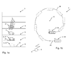
- an exemplifying parking area 3 comprising at least two floors
- an exemplifying vehicle 2 comprising a floor determining device 1 for determining on which floor f0, f1, f2, f3 of the parking area 3 the vehicle 2 is positioned, according to embodiments of the disclosure.
- the parking area 3 comprises at least two floors, and may e.g. be represented by a multi-story car park comprising any arbitrary number of floors.
- the floors f0, f1, f2, f3 of the multi-story car park are in parallel with the ground and essentially aligned in a vertical direction, i.e. arranged on top of one another.
- Ramps, on which the vehicle 2 may drive from one floor f0, f1, f2, f3 to another f0, f1, f2, f3 may be disposed and arranged in any arbitrary manner.
- the vehicle 2 which in in the shown embodiment is represented by a car, is at a current position 21, which is situated on the first floor f1.
- the vehicle 2 has driven a travelled distance 23 from a previous position 22 of the vehicle 2, here situated on the ground floor f0, to the current position 21, i.e. here upwards.
- the floor indications are merely exemplifying; the vehicle 2 may drive between any, as well as several, of the illustrated floors f0, f1, f2, f3.
- the previous position 22 is a position which horizontally coincides with the current position 21.
- the travelled distance 23 may be greater than a predetermined minimum distance, and/or shorter than a predetermined maximum distance.
- the vehicle 2 may comprise an acceleration device 4, here a throttle, a vehicle compass 5, a steering wheel 6, a positioning system 7, here a Global Positioning System, GPS, in combination with dead reckoning, a display 11 and/or a gyro 12.
- an acceleration device 4 here a throttle
- vehicle compass 5 a vehicle compass 5
- steering wheel 6 a positioning system 7, here a Global Positioning System, GPS, in combination with dead reckoning, a display 11 and/or a gyro 12.
- GPS Global Positioning System
- FIG. 1a Further illustrated in Figure 1a is an electronic device 9, which here is represented by a handheld user device, to which a value 8 may be provided by the floor determining device 1.
- Figures 1b illustrates, seen from above, an exemplifying parking area 3 comprising at least two floors, and an exemplifying vehicle 2 comprising a floor determining device 1 for determining on which floor f0, f1, f2, f3 of the parking area 3 the vehicle 2 is positioned, according to alternative embodiments of the disclosure.
- ramps on which the vehicle 2 may drive from one floor to another are disposed in a spiral manner, such that the vehicle 2 may wind around a centre axis 13 to drive from one floor f0, f1, f2, f3 to another floor f0, f1, f2, f3.
- the vehicle 2 of Figure 1b is at a current position 24, which here is situated on the second floor f2.
- the vehicle 2 has driven a travelled distance 26 from a previous position 25 of the vehicle 2, here situated on the third floor f3, to the current position 24, i.e. here downwards.
- the previous position 25 is a position from which the vehicle 2 has turned, essentially, 360 degrees, i.e. a revolution.
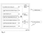
- the floor determining device 1 comprises a match determining unit 101 and a floor change determining unit 104.
- the floor change determining unit 1 may further comprise a characteristics determining unit 102, a comparing unit 103, an incrementing/decrementing unit 105, a providing unit 106, a revolution determining unit 107, and/or a horizontal positioning unit 108.
- the embodiments herein for determining on which floor f0, f1, f2, f3 of a parking area 3 a vehicle 2 is positioned may be implemented through one or more processors, such as a processor 109, here denoted CPU, together with computer program code for performing the functions and actions of the embodiments herein.
- Said program code may also be provided as a computer program product, for instance in the form of a data carrier carrying computer program code for performing the embodiments herein when being loaded into the floor determining device 1.
- One such carrier may be in the form of a CD ROM disc. It is however feasible with other data carriers such as a memory stick.
- the computer program code may furthermore be provided as pure program code on a server and downloaded to the floor determining device 1.
- the floor determining device 1 may further comprise a memory 110 comprising one or more memory units.
- the memory 110 may be arranged to be used to store e.g. information, and further to store data, configurations, schedulings, and applications, to perform the methods herein when being executed in the floor determining device 1.
- the match determining unit 101, the floor change determining unit 104, the optional characteristics determining unit 102, the optional comparing unit 103, the optional incrementing/decrementing unit 105, the optional providing unit 106, the optional revolution determining unit 107, the optional horizontal positioning unit 108, the processor 109, and the memory 110 may for instance be implemented in one or several arbitrary nodes 10.
- a node 10 may be an electronic control unit (ECU) or any suitable generic electronic device.
- match determining unit 101 may refer to a combination of analog and digital circuits, and/or one or more processors configured with software and/or firmware, e.g. stored in a memory such as the memory 110, that when executed by the one or more processors such as the processor 109 perform as will be described in more detail later on.
- processors may be included in a single ASIC (Application-Specific Integrated Circuitry), or several processors and various digital hardware may be distributed among several separate components, whether individually packaged or assembled into a SoC (System-on-a-Chip).
- ASIC Application-Specific Integrated Circuitry
- SoC System-on-a-Chip
- the revolution determining unit 107 may optionally be comprised in the match determining unit 101.
- the horizontal positioning unit 108 unit may optionally be comprised in the match determining unit 101.
- Figure 3 is a flowchart depicting an exemplifying method performed by a floor determining device 1 of a vehicle 2 for determining on which floor f0, f1, f2, f3 of a parking area 3 comprising at least two floors, a vehicle 2 is positioned, according to embodiments of the disclosure.
- the exemplifying method which may be continuously repeated, comprises the following actions discussed with support from Figures 1 and 2 . The actions may be taken in any suitable order, and even be performed simultaneously where applicable. It should be noted that the optional Action 301 may be performed irrespective of Action 302.
- the revolution determining unit 107 determines that the vehicle 2, at the current position 24, has turned 360 degrees as compared to being positioned at the previous position 25, based on compass input from the vehicle compass 5 of the vehicle 2, gyro input from the gyro 12 of the vehicle 2 and/or steering angle input from the steering wheel 6 of the vehicle 2.
- the horizontal positioning unit 108 determines that the previous position 22 horizontally coincides with the current position 21 based on positioning input from the positioning system 7, for instance Global Positioning System, GPS, and/or dead reckoning.
- the match determining unit 101 determines that the vehicle 2 at the current position 21, 24 has driven the travelled distance 23, 26 from the previous position 22, 25 of the vehicle 2, which previous position 22, 25 is a position 22 which horizontally coincides with the current position 21 and/or which previous position 22, 25 is a position 25 from which the vehicle 2 has turned 360 degrees.
- travelled distance 23, 26 is greater than a predetermined minimum distance, if a passed period of time for driving the travelled distance 23, 26 is within a predetermined maximum period of time, and/or if the travelled distance 23, 26 is shorter than a predetermined maximum distance.
- the characteristics determining unit 102 determines driving characteristics comprising acceleration and/or speed of the vehicle 2 during the travelled distance 23, 26, and corresponding required throttle output of the acceleration device 4 of the vehicle 2.
- the comparing unit 103 compares the required throttle output with default throttle output associated with driving a distance corresponding to the travelled distance 23, 26 on a plane surface, to accomplish the driving characteristics.
- the floor change determining unit 104 determines that the current position 21, 24 is situated on the higher floor f1 above the previous floor f0 of the previous position 22 if the vehicle 2 is determined to have driven the travelled distance 23, 26 more upwards than downwards from the previous position 22, 25 to the current position 21, 24.
- Action 306 of determining that the current position 21, 24 is situated on the higher floor f1 if the vehicle 2 is determined to have driven the travelled distance 23, 26 more upwards than downwards comprises determining that the current position 21, 24 is situated on the higher floor f1 if the required throttle output is higher than the default throttle output.
- the floor change determining unit 104 determines that the current position 21, 24 is situated on the lower floor beneath the previous floor f0 if the vehicle 2 is determined to have driven the travelled distance 23, 26 more downwards than upwards.
- Action 307 of determining that the current position 21, 24 is situated on the lower floor if the vehicle 2 is determined to have driven the travelled distance 23, 26 more downwards than upwards comprises determining that the current position 21, 24 is situated on the lower floor if the required throttle output is lower than the default throttle output.
- one scenario may be that it is determined that the vehicle 2 neither has driven more upwards than downwards, nor more downwards than upwards, subsequent that it has been determined 302, 303 that the current position 21 and the previous position 22 coincide vertically and/or subsequent that it has been determined 301, 303 that the previous position 25 is a position from which the vehicle has turned 360 degrees as compared to the current position 24.
- Such a scenario may for instance occur in a roundabout.
- the incrementing/decrementing unit 105 increments the value 8 of the floor counter if the current position 21, 24 is determined to be situated on the higher floor f1.
- the incrementing/decrementing unit 105 decrements the value 8 of the floor counter if the current position 21, 24 is determined to be situated on the lower floor.
- the providing unit 106 provides the value 8 to the display 11 of the vehicle 2 and/or to the remote electronic device 9.
- the method may be repeated for each floor f0, f1, f2, f3 the vehicle 2 passes / is located on.
Landscapes
- Engineering & Computer Science (AREA)
- Radar, Positioning & Navigation (AREA)
- Remote Sensing (AREA)
- Automation & Control Theory (AREA)
- Physics & Mathematics (AREA)
- General Physics & Mathematics (AREA)
- Navigation (AREA)
- Control Of Driving Devices And Active Controlling Of Vehicle (AREA)
Abstract
Description
- The present disclosure relates to a floor determining device of a vehicle and a method performed therein for determining on which floor of a parking area comprising at least two floors, the vehicle is positioned.
- To efficiently utilize available space, parking areas commonly consist of a plurality of parking floors. Such e.g. multi-story car parks, which may comprise merely a few up to a large number of parking floors, enable many vehicles to be parked simultaneously. Along with the plurality of parking floors, however, arises the problem of keeping track of on which floor a vehicle is situated, e.g. has been parked. Although with positioning systems it is possible to keep track of the horizontal positioning of the vehicle, in e.g. a digital map, it is difficult to distinguish between the different floors. Furthermore, it is not unusual that a driver simply forgets on which parking floor he or she parked, or even forgets to check the same before leaving the vehicle and subsequently the multistory car park.
-
DE 10 2011 076 245 , for instance, relates to locating a motorcar in a multi-story car park. A motorcar-side communication unit emits a pressure value, a portable user device detects pressure around the portable user device, and an evaluating device compares the pressure values. As the portable user device approaches the parking floor of the vehicle, the difference between the pressure values decreases. - Although
DE 10 2011 076 245 enables for a user carrying the portable user device to locate his or her vehicle, however, pressure sensors are a necessity. Furthermore, there is no suggestion regarding how to keep track on which floor the vehicle is positioned. - It is therefore an object of embodiments herein to provide an improved approach of determining on which floor a vehicle is situated.
- According to a first aspect of embodiments herein, the object is achieved by a method performed by a floor determining device of a vehicle for determining on which floor of a parking area comprising at least two floors, the vehicle is positioned. The floor determining unit determines, by means of a match determining unit comprised in the floor determining device, that the vehicle at a current position has driven a travelled distance from a previous position of the vehicle, which previous position is a position which horizontally coincides with the current position and/or which previous position is a position from which the vehicle has turned 360 degrees. The floor determining device determines, by means of a floor change determining unit comprised in the floor determining device, that the current position is situated on a higher floor above a previous floor of the previous position if the vehicle is determined to have driven the travelled distance more upwards than downwards from the previous position to the current position, and that the current position is situated on a lower floor beneath the previous floor if the vehicle is determined to have driven the travelled distance more downwards than upwards.
- Thereby, difficulties related to distinguishing between different floors in e.g. a multi-story car park are alleviated. That is, determining that the vehicle at a current instant is situated at a position which horizontally, i.e. seen from above, corresponds to a position at which the vehicle previously was situated, is an indication of that the vehicle may have driven up or down at least one floor. Alternatively, determining that the vehicle has turned effectively 360 degrees in one turning direction is, in a similar manner, an indication of that the vehicle may have driven up or down at least one floor. Thus, by determining if a travelled distance from a previous position to a current position has been driven more upwards than downwards, or vice versa, by analysing vehicle data associated with the vehicle during, and/or after, driving the travelled distance, it may be determined if the vehicle has moved to a higher floor, or a lower floor.
- For that reason, an improved approach is provided for determining on which floor a vehicle is situated.
- The technical features and corresponding advantages of the above mentioned method will be discussed in further detail in the following.
- By introducing a method performed by a floor determining device of a vehicle for determining on which floor of a parking area comprising at least two floors, the vehicle is positioned, an approach is provided which enables for identifying where a vehicle is positioned not merely horizontally, but also vertically. The referred to "vehicle" may be represented by any arbitrary vehicle, for instance a car, truck, lorry, van, bus, motorcycle etc. The referred to "parking area" comprising at least two floors may refer to e.g. a multi-story car park or parking garage comprising a plurality of floors intended for parking of vehicles. The floors may be arranged, e.g. aligned, on top of one another, e.g. in parallel with the ground. Alternatively and/or additionally, one or several of the floors may be arranged to have an inclination as compared to the ground. Furthermore, ramps on which the vehicle may travel to drive between different floors may be arbitrarily arranged. According to one example, a ramp may be arranged in a spiral manner, such that a vehicle, in order to go up or down one floor, may need to turn substantially 360 degrees, i.e. make a revolution.
- Since the floor determining unit determines, by means of a match determining unit comprised in the floor determining device, that the vehicle at a current position has driven a travelled distance from a previous position of the vehicle, which previous position is a position which horizontally coincides with the current position, it is determined that the vehicle at a current instant passes / is situated at a position which horizontally, i.e. seen from above, corresponds to a position which the vehicle previously passed / was situated at. That is, comparing current horizontal positioning of the vehicle with previous horizontal positioning, i.e. comparing positioning as seen from above, e.g. retrieved from a digital map provided in the vehicle, enables for determining when there is a horizontal match of a current position with a previous position. Determining that there is a horizontal match may subsequently trigger determining the travelled distance of the vehicle from the previous position to the current position. The previous position as well as the current position may, for instance, be stored in a memory. Furthermore, determining the travelled distance from the previous position to the current position may be accomplished by computing the distance the vehicle has driven from the previous position to the current position. "Horizontally coincides" is here intended to be interpreted in a broad manner, likewise including "substantially horizontally coincides". That is, the current position may slightly deviate horizontally from the previous position. Accordingly, the current position and the previous position need not necessarily be an exact horizontal match; rather, the current position may likewise be within a predetermined distance of the previous position, e.g. within a few meters. The referred to "match determining unit" may be any arbitrary unit which to some extent may be comprised in one or a combination of suitable electronic devices, such as e.g. one or several integrated arbitrary electronic control unit (ECU) nodes, adapted to receive input regarding the horizontal positioning of the vehicle, from e.g. a positioning system.
- Alternatively and/or additionally, the previous position is a position from which the vehicle has turned 360 degrees. That is, it may be determined that the vehicle at a current instant, occurring at the current position, has turned effectively 360 degrees in one turning direction as compared to a previous vehicle direction, occurring at the previous position. By "effectively turned 360 degrees" is here intended that, rather than having to turn the 360 degrees continuously in a first turning direction, the vehicle may in fact have turned also in the opposite turning direction prior to finally reaching 360 degrees in the first turning direction. Keeping track of the direction of the vehicle, and e.g. store values thereof in a memory, enables for determining when the vehicle has turned 360 degrees, which may be referred to as a "match". The vehicle having turned 360 degrees may indicate that the vehicle has made a revolution, such as e.g. driven up / down a ramp to a higher / lower floor in a multi-story car park. In a similar manner, the vehicle having turned substantially 720 degrees may indicate that the vehicle has made two revolutions. Determining that the vehicle has turned 360 degrees may subsequently trigger determining the travelled distance of the vehicle from the previous position to the current position. "360 degrees" is here intended to be interpreted in a broad manner, likewise including "substantially 360 degrees". That is, the vehicle needs not necessarily have turned exactly 360 degrees; rather the vehicle may likewise have turned almost or close to 360 degrees, e.g. at least 350 degrees, or at least 340 degrees. Alternatively, "substantially 360" degrees may refer to a range, such as e.g. 330-390 degrees. The referred to "match determining unit" may further be adapted to receive input regarding turning of the vehicle from one or a plurality of vehicle sensors.
- Since the floor determining device determines, by means of a floor change determining unit comprised in the floor determining device, that the current position is situated on a higher floor above a previous floor of the previous position if the vehicle is determined to have driven the travelled distance more upwards than downwards from the previous position to the current position, and that the current position is situated on a lower floor beneath the previous floor if the vehicle is determined to have driven the travelled distance more downwards than upwards, it is, in determining if the vehicle has driven the travelled distance more upwards than downwards, or vice versa, determined whether the current position and the previous position differ vertically, and subsequently determined whether the vehicle, at the current position, has moved up or down vertically as compared to the previous position. Thereby, it may be determined if the vehicle has moved to a higher floor, or a lower floor of e.g. a parking area comprising at least two floors. Determining if the travelled distance has been driven more upwards than downwards, or vice versa, is accomplished by analysing vehicle data associated with the vehicle during, and/or after, driving the travelled distance from the previous position to the current position. That is, determining if the vehicle has driven the travelled distance more upwards than downwards, and vice versa, from the previous position to the current position may be based on driving characteristics and/or driving parameters. Accordingly, by analysing driving parameters, such as e.g. vertical positioning at the current position as compared to the previous position, e.g. retrieved from a gyro of the vehicle, and/or analysing driving characteristics, such as e.g. acceleration, deceleration and/or speed of the vehicle during the travelled distance, it is determined if the vehicle may have changed its position effectively vertically upwards, or effectively vertically downwards. Consequently, in that the introduced method may be triggered every time there is a "match", i.e. every time it is determined that a current position coincides with a previous position and/or it is determined that the vehicle has turned 360 degrees, the method may handle the vehicle driving between any arbitrary number of floors. By "effectively" changed position vertically upwards (/downwards) is here intended that, rather than having driven the travelled distance continuously upwards (/downwards), the vehicle may in fact have driven also downwards (/upwards) to some extent prior to finally reaching the current position.
- The referred to previous floor may be any arbitrary floor associated with the previous position, such as a floor on which the vehicle is determined to have been situated when in the previous position. The referred to higher floor, which is arranged vertically higher than the previous floor, may be any arbitrary floor associated with the current position, such as a floor on which the vehicle is determined to be situated when in the current position. In a similar manner, the referred to lower floor, which is arranged vertically lower than the previous floor, may be any arbitrary floor associated with the current position, such as a floor on which the vehicle is determined to be situated when in the current position. The referred to "floor change determining unit" may be any arbitrary unit which to some extent may be comprised in one or a combination of suitable electronic devices, such as e.g. one or several integrated arbitrary electronic control unit (ECU) nodes, adapted to receive input regarding driving parameters and/or driving characteristics from one or a combination of vehicle sensors, such as e.g. a gyro indicating vertical movement, a braking device, such as e.g. a brake pedal, or an acceleration device, such as e.g. a throttle pedal.
- It should be noted that one scenario may be that it is determined that the vehicle neither has driven more upwards than downwards, nor more downwards than upwards, subsequent that it has been determined that the current position and the previous position coincide vertically and/or subsequent that it has been determined that the previous position is a position from which the vehicle has turned 360 degrees as compared to the current position. Such a scenario may for instance occur in a roundabout.
- According to an embodiment, the travelled distance may be greater than a predetermined minimum distance, a passed period of time for driving the travelled distance may be within a predetermined maximum period of time, and/or the travelled distance may be shorter than a predetermined maximum distance. Thereby, in determining that the travelled distance is greater than a minimum distance, it may subsequently be determined that the vehicle has actually moved to reach the current position from the previous position, and hence that the vehicle is not merely standing still. The minimum distance may for instance range from 30 meters down to a few meters.
- Furthermore, in determining that a passed period of time for driving the travelled distance is within a maximum period of time, it may subsequently be determined that the travelled distance is driven during a reasonable time frame, e.g. during one and the same driving occurrence. Thereby, in a scenario where the vehicle arrives at a current position horizontally coinciding with a previous position, at which previous position the vehicle was situated a fairly long time ago, e.g. the day before, such as scenario may be ignored. Miscalculations which potentially may arise from e.g. parking at the same parking area two days in a row may hence be avoided. The maximum period of time may for instance range from several weeks down to a few minutes.
- In a similar manner, in determining that the travelled distance is shorter than a predetermined maximum distance, it may subsequently be determined that the travelled distance is a reasonable distance for driving between floors of a parking area, e.g. driven during one and the same driving occurrence. Thereby, in a scenario where the vehicle arrives at a current position horizontally coinciding with a previous position, from which previous position the travelled distance to the current position is fairly long, e.g. several kilometres, such as scenario may be ignored. Miscalculations which potentially may arise from e.g. parking at the same parking area two days in a row may hence be avoided. The maximum distance may for instance range from tens of kilometres down to a few hundred meters.
- According to another embodiment, the floor determining device increments, by means of an incrementing/decrementing unit comprised in the floor determining device, a value of a floor counter if the current position is determined to be situated on the higher floor, and decrements, by means of the incrementing unit, the value of the floor counter if the current position is determined to be situated on the lower floor. Thereby, by incrementing or decrementing a value of a floor counter, a convenient manner in which to keep track of a current floor of the vehicle, is provided. The floor counter may for instance be implemented by incrementing or decrementing an integer value. The value may furthermore be initiated to zero. Initiation may for instance be based on manual input from e.g. the driver, or occur automatically provided predetermined circumstances, such as entering a parking area or the value being considered to be erroneous. The referred to "incrementing/decrementing unit" may be any arbitrary unit which to some extent may be comprised in one or a combination of suitable electronic devices, such as e.g. one or several integrated arbitrary electronic control unit (ECU) nodes, adapted to receive input regarding change of floor.
- According to a further embodiment, the floor determining device may provide, by means of a providing unit comprised in the floor determining device, the value to a display of the vehicle and/or to a remote electronic device. Thereby, the current floor on which the vehicle is considered to be situated, as indicated by the value, may be presented on an in-vehicle display and/or further processed by a remote electronic device. In providing the value to the display, e.g. a driver of the vehicle may be made aware of the current floor of the vehicle, as indicated by the value. Alternatively and/or additionally, in providing the value to a remote electronic device, such as e.g. a server or handheld user device, a user not necessarily in the vicinity of the vehicle may be made aware of the current floor of the vehicle. This may for instance be useful in a scenario where someone else than the original driver needs to locate the vehicle, e.g. another driver, or a service provider for delivery of a service. The value may, for instance, be provided once it is determined that the vehicle has parked.
- The referred to "providing unit" may be any arbitrary unit which to some extent may be comprised in one or a combination of suitable electronic devices, such as e.g. one or several integrated arbitrary electronic control unit (ECU) nodes, adapted to communicate with a display of the vehicle and/or communicate, e.g. wirelessly, with a remote electronic device. Furthermore, the referred to remote electronic device may refer to, for instance a stationary server or computer, or a handheld user device, such as e.g. a mobile terminal or wireless terminal, a mobile phone, a computer such as e.g. a laptop, a Personal Digital Assistant (PDA) or tablet computer with wireless capability, a Machine to Machine (M2M) device or any other radio network unit capable to communicate with the providing unit.
- According to yet another embodiment, the floor determining device may determine, by means of a revolution determining unit comprised in the floor determining device, that the vehicle, at the current position, has turned 360 degrees as compared to being positioned at the previous position, based on compass input from a vehicle compass of the vehicle, gyro input from a gyro of the vehicle and/or steering angle input from a steering wheel of the vehicle. Thereby, by considering input relating to the vehicle turning derived from one or a plurality of a vehicle compass, vehicle gyro and/or steering wheel, data commonly already available in the vehicle may be utilized for determining that the vehicle has turned 360 degrees. The referred to "revolution determining unit" may be any arbitrary unit which to some extent may be comprised in one or a combination of suitable electronic devices, such as e.g. one or several integrated arbitrary electronic control unit (ECU) nodes, adapted to receive input from a vehicle compass, vehicle gyro and/or steering wheel of the vehicle. Furthermore, "based on" is throughout this disclosure intended to be interpreted to likewise include at least "utilizing", "considering" and "taking into account". Additionally and/or alternatively, the floor determining device may determine, by means of the revolution determining unit comprised in the floor determining device, that the vehicle, at the current position, has turned 360 degrees as compared to being positioned at the previous position, based on turning input from one or several of the wheels of the vehicle, e.g. from one or several anti-lock braking system, ABS, sensors.
- According to still another embodiment, the floor determining device may further determine, by means of a horizontal positioning unit comprised in the floor determining device, that the previous position horizontally coincides with the current position based on positioning input from a positioning system, for instance Global Positioning System, GPS, and/or dead reckoning. Thereby, by considering input relating to the horizontal position of the vehicle derived from GPS and/or dead reckoning, data commonly already available in the vehicle may be utilized for determining that the previous position horizontally coincides with the current position. The referred to "horizontal positioning unit" may be any arbitrary unit which to some extent may be comprised in one or a combination of suitable electronic devices, such as e.g. one or several integrated arbitrary electronic control unit (ECU) nodes, adapted to receive input from a positioning system.
- According to one embodiment, the floor determining device may further determine, by means of a characteristics determining unit comprised in the floor determining device, driving characteristics comprising acceleration and/or speed of the vehicle during the travelled distance, and corresponding required throttle output, such as throttle characteristics, of an acceleration device of the vehicle. The floor determining device may further compare, by means of a comparing unit comprised in the floor determining device, the required throttle output with default throttle output associated with driving a distance corresponding to the travelled distance on a plane surface, to accomplish the driving characteristics. The determining that the current position is situated on the higher or the lower floor may comprise the floor change determining unit determining that the current position is situated on the higher floor if the required throttle output is higher than the default throttle output, and that the current position is situated on the lower floor if the required throttle output is lower than the default throttle output.
- Thereby, in considering required throttle output during the travelled distance and comparing with default throttle output, and subsequently in determining that the current position is situated on the higher / lower floor if the required throttle output is higher / lower than the default throttle output, vertical positioning of the vehicle may be accomplished. That is, since driving characteristics comprising acceleration and/or speed of the vehicle during the travelled distance is considered along with corresponding required throttle output of an acceleration device, and since the required throttle output is compared with default throttle output, i.e. hypothetical throttle output associated with driving a distance corresponding to the travelled distance on a plane surface, to accomplish the driving characteristics, it is possible to judge if the required throttle output is higher / lower than the default throttle output, and subsequently if the current position hence is situated on the higher or lower floor.
- The acceleration device may for instance be represented by an acceleration pedal, such as a throttle. Furthermore, the referred to "default throttle output" refers to hypothetical throttle output of the acceleration device associated with driving a distance corresponding to the travelled distance on a plane surface, to accomplish the previously mentioned driving characteristic comprising acceleration and/or speed of the vehicle during the travelled distance. The referred to "characteristics determining unit" may be any arbitrary unit which to some extent may be comprised in one or a combination of suitable electronic devices, such as e.g. one or several integrated arbitrary electronic control unit (ECU) nodes, adapted to receive input from an acceleration device. In a similar manner, the referred to "comparing unit" may be any arbitrary unit which to some extent may be comprised in one or a combination of suitable electronic devices, such as e.g. one or several integrated arbitrary electronic control unit (ECU) nodes.
- According to a second aspect of embodiments herein, the object is achieved by a floor determining device of a vehicle for determining on which floor of a parking area comprising at least two floors, the vehicle is positioned. The floor determining device comprises a match determining unit adapted for determining that the vehicle at a current position has driven a travelled distance from a previous position of the vehicle, which previous position is a position which horizontally coincides with the current position and/or which previous position is a position from which the vehicle has turned 360 degrees. The floor determining device further comprises a floor change determining unit adapted for determining that the current position is situated on a higher floor above a previous floor of the previous position if the vehicle is determined to have driven the travelled distance more upwards than downwards from the previous position to the current position, and that the current position is situated on a lower floor beneath the previous floor if the vehicle is determined to have driven the travelled distance more downwards than upwards. According to an embodiment, the travelled distance may be greater than a predetermined minimum distance, a passed period of time for driving the travelled distance may be within a predetermined maximum period of time, and/or the travelled distance may be shorter than a predetermined maximum distance.
- According to another embodiment, the floor determining device may further comprise an incrementing/decrementing unit adapted for incrementing a value of a floor counter if the current position is determined to be situated on the higher floor, and for decrementing the value of the floor counter if the current position is determined to be situated on the lower floor.
- According to a further embodiment, the floor determining device may further comprise a providing unit adapted for providing the value to a display of the vehicle and/or to a remote electronic device.
- According to yet another embodiment, the floor determining device may further comprise a revolution determining unit adapted for determining that the vehicle, at said current position, has turned 360 degrees as compared to being positioned at the previous position, based on compass input from a vehicle compass of the vehicle, gyro input from a gyro of the vehicle and/or steering angle input from a steering wheel of the vehicle.
- According to still another embodiment, the floor determining device may further comprise a horizontal positioning unit adapted for determining that the previous position horizontally coincides with the current position based on positioning input from a positioning system, for instance Global Positioning System, GPS, and/or dead reckoning.
- According to one embodiment, the floor determining unit may further comprise a characteristics determining unit adapted for determining driving characteristics comprising acceleration and/or speed of the vehicle during the travelled distance, and corresponding required throttle output of an acceleration device of the vehicle. The floor determining unit may further comprise a comparing unit adapted for comparing the required throttle output with default throttle output associated with driving a distance corresponding to the travelled distance on a plane surface, to accomplish the driving characteristics. The floor change determining unit may further be adapted for determining that the current position is situated on the higher floor if the required throttle output is higher than the default throttle output, and adapted for determining that the current position is situated on the lower floor if the required throttle output is lower than the default throttle output.
- Similar advantages as those mentioned in the foregoing in relation to the first aspect correspondingly apply to the second aspect, why these advantages are not further discussed.
- According to a third aspect of embodiments herein, the object is achieved by a vehicle comprising the previously mentioned floor determining device. Yet again, similar advantages as those mentioned in the foregoing in relation to the first aspect correspondingly apply to the third aspect, why these advantages are not further discussed.
- The various aspects of the non-limiting embodiments of the invention, including particular features and advantages, will be readily understood from the following detailed description and the accompanying drawings, in which:
-
Figure 1a illustrates an exemplifying parking area comprising at least two floors, and an exemplifying vehicle comprising a floor determining device for determining on which floor of the parking area the vehicle is positioned, according to embodiments of the disclosure; -
Figure 1b illustrates an exemplifying parking area comprising at least two floors, and an exemplifying vehicle comprising a floor determining device for determining on which floor of the parking area the vehicle is positioned, according to alternative embodiments of the disclosure; -
Figure 2 is a schematic block diagram illustrating a floor determining device according to embodiments of the disclosure; and -
Figure 3 is a flowchart depicting an exemplifying method for determining on which floor of a parking area a vehicle is positioned, according to embodiments of the disclosure. - The non-limiting embodiments of the present disclosure will now be described more fully hereinafter with reference to the accompanying drawings, in which currently preferred embodiments of the disclosure are shown. This disclosure may, however, be embodied in many different forms and should not be construed as limited to the embodiments set forth herein. Like reference characters refer to like elements throughout. Dashed lines of some boxes in the figures indicate that these units or actions are optional and not mandatory.
- In the following, according to embodiments herein which relate to a
floor determining device 1 of avehicle 2 and a method therein for determining on which floor f0, f1, f2, f3 of aparking area 3 thevehicle 2 is positioned, there will be disclosed an approach for distinguishing between different floors of theparking area 3. - Referring now to the figures and
Figure 1a in particular, there is depicted, in a schematic side view, an exemplifyingparking area 3 comprising at least two floors, and an exemplifyingvehicle 2 comprising afloor determining device 1 for determining on which floor f0, f1, f2, f3 of theparking area 3 thevehicle 2 is positioned, according to embodiments of the disclosure. Theparking area 3 comprises at least two floors, and may e.g. be represented by a multi-story car park comprising any arbitrary number of floors. In the illustrated embodiment, the floors f0, f1, f2, f3 of the multi-story car park are in parallel with the ground and essentially aligned in a vertical direction, i.e. arranged on top of one another. Ramps, on which thevehicle 2 may drive from one floor f0, f1, f2, f3 to another f0, f1, f2, f3 may be disposed and arranged in any arbitrary manner. - The
vehicle 2, which in in the shown embodiment is represented by a car, is at a current position 21, which is situated on the first floor f1. Thevehicle 2 has driven a travelleddistance 23 from a previous position 22 of thevehicle 2, here situated on the ground floor f0, to the current position 21, i.e. here upwards. It should be noted that the floor indications are merely exemplifying; thevehicle 2 may drive between any, as well as several, of the illustrated floors f0, f1, f2, f3. The previous position 22 is a position which horizontally coincides with the current position 21. Furthermore, the travelleddistance 23 may be greater than a predetermined minimum distance, and/or shorter than a predetermined maximum distance. - The
vehicle 2 may comprise an acceleration device 4, here a throttle, a vehicle compass 5, a steering wheel 6, a positioning system 7, here a Global Positioning System, GPS, in combination with dead reckoning, adisplay 11 and/or agyro 12. - Further illustrated in
Figure 1a is anelectronic device 9, which here is represented by a handheld user device, to which avalue 8 may be provided by thefloor determining device 1. -
Figures 1b illustrates, seen from above, an exemplifyingparking area 3 comprising at least two floors, and an exemplifyingvehicle 2 comprising afloor determining device 1 for determining on which floor f0, f1, f2, f3 of theparking area 3 thevehicle 2 is positioned, according to alternative embodiments of the disclosure. - In the illustrated embodiment of
Figure 1b , ramps on which thevehicle 2 may drive from one floor to another, are disposed in a spiral manner, such that thevehicle 2 may wind around acentre axis 13 to drive from one floor f0, f1, f2, f3 to another floor f0, f1, f2, f3. - The
vehicle 2 ofFigure 1b , is at a current position 24, which here is situated on the second floor f2. Thevehicle 2 has driven a travelleddistance 26 from aprevious position 25 of thevehicle 2, here situated on the third floor f3, to the current position 24, i.e. here downwards. Theprevious position 25 is a position from which thevehicle 2 has turned, essentially, 360 degrees, i.e. a revolution. - As further shown in
Figure 2 , which depicts a schematic block diagram illustrating afloor determining device 1 according to embodiments of the disclosure, thefloor determining device 1 comprises amatch determining unit 101 and a floorchange determining unit 104. The floorchange determining unit 1 may further comprise acharacteristics determining unit 102, a comparingunit 103, an incrementing/decrementing unit 105, a providingunit 106, arevolution determining unit 107, and/or ahorizontal positioning unit 108. Furthermore, the embodiments herein for determining on which floor f0, f1, f2, f3 of a parking area 3 avehicle 2 is positioned, may be implemented through one or more processors, such as aprocessor 109, here denoted CPU, together with computer program code for performing the functions and actions of the embodiments herein. Said program code may also be provided as a computer program product, for instance in the form of a data carrier carrying computer program code for performing the embodiments herein when being loaded into thefloor determining device 1. One such carrier may be in the form of a CD ROM disc. It is however feasible with other data carriers such as a memory stick. The computer program code may furthermore be provided as pure program code on a server and downloaded to thefloor determining device 1. - The
floor determining device 1 may further comprise amemory 110 comprising one or more memory units. Thememory 110 may be arranged to be used to store e.g. information, and further to store data, configurations, schedulings, and applications, to perform the methods herein when being executed in thefloor determining device 1. Furthermore, thematch determining unit 101, the floorchange determining unit 104, the optionalcharacteristics determining unit 102, the optional comparingunit 103, the optional incrementing/decrementing unit 105, the optional providingunit 106, the optionalrevolution determining unit 107, the optionalhorizontal positioning unit 108, theprocessor 109, and thememory 110 may for instance be implemented in one or severalarbitrary nodes 10. Anode 10 may be an electronic control unit (ECU) or any suitable generic electronic device. Those skilled in the art will also appreciate that thematch determining unit 101, the floorchange determining unit 104, the optionalcharacteristics determining unit 102, the optional comparingunit 103, the optional incrementing/decrementing unit 105, the optional providingunit 106, the optionalrevolution determining unit 107, and the optionalhorizontal positioning unit 108 described above, and which will be described in more detail later on in this description, may refer to a combination of analog and digital circuits, and/or one or more processors configured with software and/or firmware, e.g. stored in a memory such as thememory 110, that when executed by the one or more processors such as theprocessor 109 perform as will be described in more detail later on. One or more of these processors, as well as the other digital hardware, may be included in a single ASIC (Application-Specific Integrated Circuitry), or several processors and various digital hardware may be distributed among several separate components, whether individually packaged or assembled into a SoC (System-on-a-Chip). - The
revolution determining unit 107 may optionally be comprised in thematch determining unit 101. In a similar manner, thehorizontal positioning unit 108 unit may optionally be comprised in thematch determining unit 101. -
Figure 3 is a flowchart depicting an exemplifying method performed by afloor determining device 1 of avehicle 2 for determining on which floor f0, f1, f2, f3 of aparking area 3 comprising at least two floors, avehicle 2 is positioned, according to embodiments of the disclosure. The exemplifying method, which may be continuously repeated, comprises the following actions discussed with support fromFigures 1 and2 . The actions may be taken in any suitable order, and even be performed simultaneously where applicable. It should be noted that the optional Action 301 may be performed irrespective of Action 302. - In optional Action 301, the
revolution determining unit 107 determines that thevehicle 2, at the current position 24, has turned 360 degrees as compared to being positioned at theprevious position 25, based on compass input from the vehicle compass 5 of thevehicle 2, gyro input from thegyro 12 of thevehicle 2 and/or steering angle input from the steering wheel 6 of thevehicle 2. - In optional Action 302, the
horizontal positioning unit 108 determines that the previous position 22 horizontally coincides with the current position 21 based on positioning input from the positioning system 7, for instance Global Positioning System, GPS, and/or dead reckoning. - In Action 303, the
match determining unit 101 determines that thevehicle 2 at the current position 21, 24 has driven the travelleddistance previous position 22, 25 of thevehicle 2, whichprevious position 22, 25 is a position 22 which horizontally coincides with the current position 21 and/or whichprevious position 22, 25 is aposition 25 from which thevehicle 2 has turned 360 degrees. - Optionally, it is determined if the travelled
distance distance distance - In
optional Action 304, thecharacteristics determining unit 102 determines driving characteristics comprising acceleration and/or speed of thevehicle 2 during the travelleddistance vehicle 2. - In
optional Action 305, the comparingunit 103 compares the required throttle output with default throttle output associated with driving a distance corresponding to the travelleddistance - In
Action 306, the floorchange determining unit 104 determines that the current position 21, 24 is situated on the higher floor f1 above the previous floor f0 of the previous position 22 if thevehicle 2 is determined to have driven the travelleddistance previous position 22, 25 to the current position 21, 24. - Optionally,
Action 306 of determining that the current position 21, 24 is situated on the higher floor f1 if thevehicle 2 is determined to have driven the travelleddistance - In
Action 307, the floorchange determining unit 104 determines that the current position 21, 24 is situated on the lower floor beneath the previous floor f0 if thevehicle 2 is determined to have driven the travelleddistance - Optionally,
Action 307 of determining that the current position 21, 24 is situated on the lower floor if thevehicle 2 is determined to have driven the travelleddistance - It should be noted that one scenario may be that it is determined that the
vehicle 2 neither has driven more upwards than downwards, nor more downwards than upwards, subsequent that it has been determined 302, 303 that the current position 21 and the previous position 22 coincide vertically and/or subsequent that it has been determined 301, 303 that theprevious position 25 is a position from which the vehicle has turned 360 degrees as compared to the current position 24. Such a scenario may for instance occur in a roundabout. - In
optional Action 308, the incrementing/decrementing unit 105 increments thevalue 8 of the floor counter if the current position 21, 24 is determined to be situated on the higher floor f1. - In
optional Action 309, the incrementing/decrementing unit 105 decrements thevalue 8 of the floor counter if the current position 21, 24 is determined to be situated on the lower floor. - In
optional Action 310, the providingunit 106 provides thevalue 8 to thedisplay 11 of thevehicle 2 and/or to the remoteelectronic device 9. - Consequently, according to the floor determining described in the foregoing, by determining if a travelled
distance previous position 22, 25 to a current position 21, 24 has been driven more upwards than downwards, or vice versa, by analysing vehicle data associated with thevehicle 2 during, and/or after, driving the travelleddistance vehicle 2 has moved to a higher floor f1, or a lower floor. Furthermore, since the introduced method may be triggered every time there is a "match", i.e. every time it is determined that a current position 21 coincides with a previous position 22 and/or it is determined that the vehicle has turned 360 degrees, the method may be repeated for each floor f0, f1, f2, f3 thevehicle 2 passes / is located on. - The person skilled in the art realizes that the present disclosure by no means is limited to the preferred embodiments described above. On the contrary, many modifications and variations are possible within the scope of the appended claims. It should furthermore be noted that the drawings not necessarily are to scale and the dimensions of certain features may have been exaggerated for the sake of clarity. Emphasis is instead placed upon illustrating the principle of the embodiments herein. Additionally, in the claims, the word "comprising" does not exclude other elements or steps, and the indefinite article "a" or "an" does not exclude a plurality.
Claims (15)
- A method performed by a floor determining device (1) of a vehicle (2) for determining on which floor (f0, f1, f2, f3) of a parking area (3) comprising at least two floors, said vehicle (2) is positioned, said method comprising:determining (303), by means of a match determining unit (101) comprised in said floor determining device (1), that said vehicle (2) at a current position (21, 24) has driven a travelled distance (23, 26) from a previous position (22, 25) of said vehicle (2), which previous position (22, 25) is a position (22) which horizontally coincides with said current position (21) and/or which previous position (22, 25) is a position (25) from which said vehicle (2) has turned 360 degrees; anddetermining (306), by means of a floor change determining unit (104) comprised in said floor determining device (1), that said current position (21, 24) is situated on a higher floor (f1) above a previous floor (f0) of said previous position (22) if said vehicle (2) is determined to have driven said travelled distance (23, 26) more upwards than downwards from said previous position (22, 25) to said current position (21, 24), and (307) that said current position (21, 24) is situated on a lower floor beneath said previous floor (f0) if said vehicle (2) is determined to have driven said travelled distance (23, 26) more downwards than upwards.
- The method according to claim 1, wherein said travelled distance (23, 26) is greater than a predetermined minimum distance, a passed period of time for driving said travelled distance (23, 26) is within a predetermined maximum period of time, and/or said travelled distance (23, 26) is shorter than a predetermined maximum distance.
- The method according to claim 1 or 2, further comprising:incrementing (308), by means of an incrementing/decrementing unit (105) comprised in said floor determining device (1), a value (8) of a floor counter if said current position (21, 24) is determined (306) to be situated on said higher floor (f1), anddecrementing (309), by means of said incrementing unit (105), said value (8) of the floor counter if said current position (21, 24) is determined (307) to be situated on said lower floor.
- The method according to claim 3, further comprising:providing (310), by means of a providing unit (106) comprised in said floor determining device (1), said value (8) to a display (11) of said vehicle (2) and/or to a remote electronic device (9).
- The method according to any one of claims 1 to 4, further comprising:determining (301), by means of a revolution determining unit (107) comprised in said floor determining device (1), that said vehicle (2), at said current position (24), has turned 360 degrees as compared to being positioned at said previous position (25), based on compass input from a vehicle compass (5) of said vehicle (2), gyro input from a gyro (12) of said vehicle (2) and/or steering angle input from a steering wheel (6) of said vehicle (2).
- The method according to any one of claims 1 to 5, further comprising:determining (302), by means of a horizontal positioning unit (108) comprised in said floor determining device (1), that said previous position (22) horizontally coincides with said current position (21) based on positioning input from a positioning system (7), for instance Global Positioning System, GPS, and/or dead reckoning.
- The method according to any one of claims 1 to 6, further comprising:determining (304), by means of a characteristics determining unit (102) comprised in said floor determining device (1), driving characteristics comprising acceleration and/or speed of said vehicle (2) during said travelled distance (23, 26), and corresponding required throttle output of an acceleration device (4) of said vehicle (2); andcomparing (305), by means of a comparing unit (103) comprised in said floor determining device (1), said required throttle output with default throttle output associated with driving a distance corresponding to said travelled distance (23, 26) on a plane surface, to accomplish said driving characteristics;wherein said determining (306, 307) that the current position (21, 24) is situated on said higher or said lower floor comprises determining that said current position (21, 24) is situated on the higher floor (f1) if said required throttle output is higher than said default throttle output, and that said current position (21, 24) is situated on the lower floor if said required throttle output is lower than said default throttle output.
- A floor determining device (1) of a vehicle (2) for determining on which floor (f0, f1, f2, f3) of a parking area (3) comprising at least two floors, said vehicle (2) is positioned, said floor determining device (1) comprising:a match determining unit (101) adapted for determining (303) that said vehicle (2) at a current position (21, 24) has driven a travelled distance (23, 26) from a previous position (22, 25) of said vehicle (2), which previous position (22, 25) is a position (22) which horizontally coincides with said current position (21) and/or which previous position (22, 25) is a position (25) from which said vehicle (2) has turned 360 degrees; anda floor change determining unit (104) adapted for determining (306) that said current position (21, 24) is situated on a higher floor (f1) above a previous floor (f0) of said previous position (22) if said vehicle (2) is determined to have driven said travelled distance (23, 26) more upwards than downwards from said previous position (22, 25) to said current position (21, 24), and (307) that said current position (21, 24) is situated on a lower floor beneath said previous floor (f0) if said vehicle (2) is determined to have driven said travelled distance (23, 26) more downwards than upwards.
- The floor determining device (1) according to claim 8, wherein said travelled distance (23, 26) is greater than a predetermined minimum distance, a passed period of time for driving said travelled distance (23, 26) is within a predetermined maximum period of time, and/or said travelled distance (23, 26) is shorter than a predetermined maximum distance.
- The floor determining device (1) according to claim 8 or 9, further comprising an incrementing/decrementing unit (105) adapted for:incrementing (308) a value (8) of a floor counter if said current position (21, 24) is determined (306) to be situated on said higher floor (f1), anddecrementing (309) said value (8) of the floor counter if said current position (21, 24) is determined (305) to be situated on said lower floor.
- The floor determining device (1) according to claim 10, further comprising:a providing unit (106) adapted for providing (310) said value (8) to a display (11) of said vehicle (2) and/or to a remote electronic device (9).
- The floor determining device (1) according to any one of claims 8 to 11, further comprising:a revolution determining unit (107) adapted for determining (301) that said vehicle (2), at said current position (24), has turned 360 degrees as compared to being positioned at said previous position (25), based on compass input from a vehicle compass (5) of said vehicle (2), gyro input from a gyro (12) of said vehicle (2) and/or steering angle input from a steering wheel (6) of said vehicle (2).
- The floor determining device (1) according to any one of claims 8 to 12, further comprising:a horizontal positioning unit (108) adapted for determining (302) that said previous position (22) horizontally coincides with said current position (21) based on positioning input from a positioning system (7), for instance Global Positioning System, GPS, and/or dead reckoning.
- The floor determining device (1) according to any one of claims 8 to 13, further comprising:a characteristics determining unit (102) adapted for determining (304) driving characteristics comprising acceleration and/or speed of said vehicle (2) during said travelled distance (23, 26), and corresponding required throttle output of an acceleration device (4) of said vehicle (2); anda comparing unit (103) adapted for comparing (305) said required throttle output with default throttle output associated with driving a distance corresponding to said travelled distance (23, 26) on a plane surface, to accomplish said driving characteristics;wherein said floor change determining unit (104) further is adapted for determining that said current position (21, 24) is situated on said higher floor (f1) if said required throttle output is higher than said default throttle output, and for determining that said current position (21, 24) is situated on said lower floor if said required throttle output is lower than said default throttle output.
- A vehicle (2) comprising the floor determining device (1) of any one of claims 8 to 14.
Priority Applications (4)
| Application Number | Priority Date | Filing Date | Title |
|---|---|---|---|
| EP14168292.2A EP2944922B1 (en) | 2014-05-14 | 2014-05-14 | Method and system for determining on which floor of a parking area a vehicle is positioned |
| US14/705,427 US9593950B2 (en) | 2014-05-14 | 2015-05-06 | Method and system for determining on which floor of a parking structure area a vehicle is positioned |
| CN201510229319.6A CN105094795B (en) | 2014-05-14 | 2015-05-07 | Method and system for determining which floor of a parking area a vehicle is placed on |
| PCT/EP2015/060589 WO2015173300A1 (en) | 2014-05-14 | 2015-05-13 | Method and system for determining on which floor of a parking area a vehicle is positioned. |
Applications Claiming Priority (1)
| Application Number | Priority Date | Filing Date | Title |
|---|---|---|---|
| EP14168292.2A EP2944922B1 (en) | 2014-05-14 | 2014-05-14 | Method and system for determining on which floor of a parking area a vehicle is positioned |
Publications (2)
| Publication Number | Publication Date |
|---|---|
| EP2944922A1 true EP2944922A1 (en) | 2015-11-18 |
| EP2944922B1 EP2944922B1 (en) | 2017-08-16 |
Family
ID=50693543
Family Applications (1)
| Application Number | Title | Priority Date | Filing Date |
|---|---|---|---|
| EP14168292.2A Active EP2944922B1 (en) | 2014-05-14 | 2014-05-14 | Method and system for determining on which floor of a parking area a vehicle is positioned |
Country Status (4)
| Country | Link |
|---|---|
| US (1) | US9593950B2 (en) |
| EP (1) | EP2944922B1 (en) |
| CN (1) | CN105094795B (en) |
| WO (1) | WO2015173300A1 (en) |
Cited By (1)
| Publication number | Priority date | Publication date | Assignee | Title |
|---|---|---|---|---|
| CN106772526A (en) * | 2017-02-22 | 2017-05-31 | 扬州源悦信息技术研究院有限公司 | A kind of automobile aided positioning system and its method of work |
Families Citing this family (11)
| Publication number | Priority date | Publication date | Assignee | Title |
|---|---|---|---|---|
| CN105608925A (en) * | 2016-03-15 | 2016-05-25 | 常州信息职业技术学院 | Parking stall reserving and vehicle searching method in parking lot |
| CN105928533B (en) * | 2016-04-26 | 2019-03-29 | 北京小米移动软件有限公司 | Air navigation aid and device, electronic equipment |
| CN108492549A (en) * | 2018-04-18 | 2018-09-04 | 北京山和朋友们科技有限公司 | A kind of vehicle parking location recognition method and vehicle parking position-recognizing system |
| US10769956B2 (en) * | 2019-01-23 | 2020-09-08 | Nanning Fugui Precision Industrial Co., Ltd. | Method and system for finding a parked vehicle |
| JP2020160617A (en) * | 2019-03-25 | 2020-10-01 | 本田技研工業株式会社 | Travel route link generation device and travel route link generation method |
| US11002546B2 (en) * | 2019-04-05 | 2021-05-11 | Toyota Connected North America, Inc. | Systems and methods for determining a location of a vehicle within a structure |
| CN110412630A (en) * | 2019-08-06 | 2019-11-05 | 深圳市元征科技股份有限公司 | Vehicle positioning method and relevant apparatus in a kind of garage |
| CN112556694A (en) * | 2019-09-26 | 2021-03-26 | 北京宝沃汽车有限公司 | Vehicle positioning method and device, storage medium and electronic equipment |
| CN111192470B (en) * | 2020-01-03 | 2021-12-24 | 深圳市星砺达科技有限公司 | Parking lot parking layer positioning method and device, computer equipment and storage medium |
| EP3996065A1 (en) * | 2020-11-10 | 2022-05-11 | Wejo Ltd. | System and method for parking tracking using vehicle event data |
| US12385748B2 (en) | 2022-09-29 | 2025-08-12 | Here Global B.V. | Systems and methods for detecting and mapping LIDAR blind spots in parking garages |
Citations (4)
| Publication number | Priority date | Publication date | Assignee | Title |
|---|---|---|---|---|
| US5925087A (en) * | 1992-08-27 | 1999-07-20 | Hitachi, Ltd. | Method and apparatus for eliminating noise in a slope estimation arrangement for a motor vehicle |
| US20090312975A1 (en) * | 2008-06-11 | 2009-12-17 | Peter Van Wyck Loomis | Forward-looking altitude detector |
| DE102011076245A1 (en) | 2011-05-20 | 2012-07-12 | Continental Automotive Gmbh | Arrangement for locating motorcar in multi-storey car park with different height levels in e.g. airport, has evaluating device comparing pressure values and outputting signal based on ratio of pressure values |
| US20130297198A1 (en) * | 2010-12-20 | 2013-11-07 | Tomtom Belgium N.V. | Method for generating map data |
Family Cites Families (2)
| Publication number | Priority date | Publication date | Assignee | Title |
|---|---|---|---|---|
| US4279563A (en) * | 1979-07-05 | 1981-07-21 | American Sterilizer Company | Unmanned material handling system for servicing a multi-level structure |
| TW201227604A (en) * | 2010-12-24 | 2012-07-01 | Tele Atlas Bv | Method for generating map data |
-
2014
- 2014-05-14 EP EP14168292.2A patent/EP2944922B1/en active Active
-
2015
- 2015-05-06 US US14/705,427 patent/US9593950B2/en not_active Expired - Fee Related
- 2015-05-07 CN CN201510229319.6A patent/CN105094795B/en active Active
- 2015-05-13 WO PCT/EP2015/060589 patent/WO2015173300A1/en not_active Ceased
Patent Citations (4)
| Publication number | Priority date | Publication date | Assignee | Title |
|---|---|---|---|---|
| US5925087A (en) * | 1992-08-27 | 1999-07-20 | Hitachi, Ltd. | Method and apparatus for eliminating noise in a slope estimation arrangement for a motor vehicle |
| US20090312975A1 (en) * | 2008-06-11 | 2009-12-17 | Peter Van Wyck Loomis | Forward-looking altitude detector |
| US20130297198A1 (en) * | 2010-12-20 | 2013-11-07 | Tomtom Belgium N.V. | Method for generating map data |
| DE102011076245A1 (en) | 2011-05-20 | 2012-07-12 | Continental Automotive Gmbh | Arrangement for locating motorcar in multi-storey car park with different height levels in e.g. airport, has evaluating device comparing pressure values and outputting signal based on ratio of pressure values |
Cited By (2)
| Publication number | Priority date | Publication date | Assignee | Title |
|---|---|---|---|---|
| CN106772526A (en) * | 2017-02-22 | 2017-05-31 | 扬州源悦信息技术研究院有限公司 | A kind of automobile aided positioning system and its method of work |
| CN106772526B (en) * | 2017-02-22 | 2019-08-09 | 扬州源悦信息技术研究院有限公司 | A vehicle auxiliary positioning system and its working method |
Also Published As
| Publication number | Publication date |
|---|---|
| EP2944922B1 (en) | 2017-08-16 |
| WO2015173300A1 (en) | 2015-11-19 |
| CN105094795A (en) | 2015-11-25 |
| US9593950B2 (en) | 2017-03-14 |
| WO2015173300A9 (en) | 2016-09-22 |
| CN105094795B (en) | 2020-03-10 |
| US20150330788A1 (en) | 2015-11-19 |
Similar Documents
| Publication | Publication Date | Title |
|---|---|---|
| EP2944922B1 (en) | Method and system for determining on which floor of a parking area a vehicle is positioned | |
| US9188445B2 (en) | System and method for storing and recalling location data | |
| CN106985814B (en) | System and method for automatically activating autonomous parking | |
| US11709501B2 (en) | System and method for controlling an autonomous vehicle | |
| US20220333934A1 (en) | Systems and methods for generating scenic routes | |
| CN106871914A (en) | The control method of vehicle and vehicle | |
| US10264402B2 (en) | Method and system for selectively enabling a user device on the move to utilize digital content associated with entities ahead | |
| CN109068281B (en) | Tracking wireless devices using seamless handover between vehicles and mobile devices | |
| CN112700201A (en) | Goods source recommendation method, electronic device and storage medium | |
| CN111192470A (en) | Parking floor positioning method, device, computer equipment and storage medium | |
| AU2017366557A1 (en) | Autonomous vehicle | |
| CN106952497A (en) | Underground garage intelligent positioning and dynamic display system and method based on RFID | |
| CN108399214A (en) | Determine the Friction dates of target vehicle | |
| CN111462511A (en) | A driving reminder method, device and electronic device | |
| US10877473B2 (en) | Method, apparatus and computer program product for differential policy enforcement for roadways | |
| CN118776559A (en) | Device method for displaying indoor driving information using map information and motion sensors | |
| US9273977B2 (en) | Method of setting via-point in navigation system | |
| US10703366B2 (en) | Inhibiting highway assist mode | |
| US10527451B2 (en) | Method and system for in a timed manner enabling a user device on the move to utilize digital content associated with entities ahead | |
| US20230098178A1 (en) | Systems and methods for evaluating vehicle occupant behavior | |
| CN113108805A (en) | Travel route recommendation method and device, electronic device and readable storage medium | |
| US12233781B2 (en) | Systems and methods for providing vehicle payload assistance | |
| US9625263B2 (en) | Method and system for ascertaining at least one road-related information item | |
| US20260057773A1 (en) | Method to contextualize proximity sensing around vehicles to reduce alarm fatigue | |
| JP2012202800A (en) | Navigation device |
Legal Events
| Date | Code | Title | Description |
|---|---|---|---|
| PUAI | Public reference made under article 153(3) epc to a published international application that has entered the european phase |
Free format text: ORIGINAL CODE: 0009012 |
|
| AK | Designated contracting states |
Kind code of ref document: A1 Designated state(s): AL AT BE BG CH CY CZ DE DK EE ES FI FR GB GR HR HU IE IS IT LI LT LU LV MC MK MT NL NO PL PT RO RS SE SI SK SM TR |
|
| AX | Request for extension of the european patent |
Extension state: BA ME |
|
| 17P | Request for examination filed |
Effective date: 20160518 |
|
| RBV | Designated contracting states (corrected) |
Designated state(s): AL AT BE BG CH CY CZ DE DK EE ES FI FR GB GR HR HU IE IS IT LI LT LU LV MC MK MT NL NO PL PT RO RS SE SI SK SM TR |
|
| REG | Reference to a national code |
Ref country code: DE Ref legal event code: R079 Ref document number: 602014013103 Country of ref document: DE Free format text: PREVIOUS MAIN CLASS: G01C0021200000 Ipc: G01C0021000000 |
|
| RIC1 | Information provided on ipc code assigned before grant |
Ipc: G01C 21/00 20060101AFI20161031BHEP Ipc: G01C 21/20 20060101ALI20161031BHEP |
|
| GRAP | Despatch of communication of intention to grant a patent |
Free format text: ORIGINAL CODE: EPIDOSNIGR1 |
|
| INTG | Intention to grant announced |
Effective date: 20170410 |
|
| GRAS | Grant fee paid |
Free format text: ORIGINAL CODE: EPIDOSNIGR3 |
|
| GRAA | (expected) grant |
Free format text: ORIGINAL CODE: 0009210 |
|
| AK | Designated contracting states |
Kind code of ref document: B1 Designated state(s): AL AT BE BG CH CY CZ DE DK EE ES FI FR GB GR HR HU IE IS IT LI LT LU LV MC MK MT NL NO PL PT RO RS SE SI SK SM TR |
|
| REG | Reference to a national code |
Ref country code: GB Ref legal event code: FG4D |
|
| REG | Reference to a national code |
Ref country code: CH Ref legal event code: EP |
|
| REG | Reference to a national code |
Ref country code: IE Ref legal event code: FG4D |
|
| REG | Reference to a national code |
Ref country code: AT Ref legal event code: REF Ref document number: 919498 Country of ref document: AT Kind code of ref document: T Effective date: 20170915 |
|
| REG | Reference to a national code |
Ref country code: DE Ref legal event code: R096 Ref document number: 602014013103 Country of ref document: DE |
|
| REG | Reference to a national code |
Ref country code: SE Ref legal event code: TRGR |
|
| REG | Reference to a national code |
Ref country code: NL Ref legal event code: MP Effective date: 20170816 |
|
| REG | Reference to a national code |
Ref country code: LT Ref legal event code: MG4D |
|
| REG | Reference to a national code |
Ref country code: AT Ref legal event code: MK05 Ref document number: 919498 Country of ref document: AT Kind code of ref document: T Effective date: 20170816 |
|
| PG25 | Lapsed in a contracting state [announced via postgrant information from national office to epo] |
Ref country code: FI Free format text: LAPSE BECAUSE OF FAILURE TO SUBMIT A TRANSLATION OF THE DESCRIPTION OR TO PAY THE FEE WITHIN THE PRESCRIBED TIME-LIMIT Effective date: 20170816 Ref country code: NL Free format text: LAPSE BECAUSE OF FAILURE TO SUBMIT A TRANSLATION OF THE DESCRIPTION OR TO PAY THE FEE WITHIN THE PRESCRIBED TIME-LIMIT Effective date: 20170816 Ref country code: NO Free format text: LAPSE BECAUSE OF FAILURE TO SUBMIT A TRANSLATION OF THE DESCRIPTION OR TO PAY THE FEE WITHIN THE PRESCRIBED TIME-LIMIT Effective date: 20171116 Ref country code: LT Free format text: LAPSE BECAUSE OF FAILURE TO SUBMIT A TRANSLATION OF THE DESCRIPTION OR TO PAY THE FEE WITHIN THE PRESCRIBED TIME-LIMIT Effective date: 20170816 Ref country code: AT Free format text: LAPSE BECAUSE OF FAILURE TO SUBMIT A TRANSLATION OF THE DESCRIPTION OR TO PAY THE FEE WITHIN THE PRESCRIBED TIME-LIMIT Effective date: 20170816 |
|
| PG25 | Lapsed in a contracting state [announced via postgrant information from national office to epo] |
Ref country code: PL Free format text: LAPSE BECAUSE OF FAILURE TO SUBMIT A TRANSLATION OF THE DESCRIPTION OR TO PAY THE FEE WITHIN THE PRESCRIBED TIME-LIMIT Effective date: 20170816 Ref country code: ES Free format text: LAPSE BECAUSE OF FAILURE TO SUBMIT A TRANSLATION OF THE DESCRIPTION OR TO PAY THE FEE WITHIN THE PRESCRIBED TIME-LIMIT Effective date: 20170816 Ref country code: RS Free format text: LAPSE BECAUSE OF FAILURE TO SUBMIT A TRANSLATION OF THE DESCRIPTION OR TO PAY THE FEE WITHIN THE PRESCRIBED TIME-LIMIT Effective date: 20170816 Ref country code: LV Free format text: LAPSE BECAUSE OF FAILURE TO SUBMIT A TRANSLATION OF THE DESCRIPTION OR TO PAY THE FEE WITHIN THE PRESCRIBED TIME-LIMIT Effective date: 20170816 Ref country code: IS Free format text: LAPSE BECAUSE OF FAILURE TO SUBMIT A TRANSLATION OF THE DESCRIPTION OR TO PAY THE FEE WITHIN THE PRESCRIBED TIME-LIMIT Effective date: 20171216 Ref country code: BG Free format text: LAPSE BECAUSE OF FAILURE TO SUBMIT A TRANSLATION OF THE DESCRIPTION OR TO PAY THE FEE WITHIN THE PRESCRIBED TIME-LIMIT Effective date: 20171116 Ref country code: GR Free format text: LAPSE BECAUSE OF FAILURE TO SUBMIT A TRANSLATION OF THE DESCRIPTION OR TO PAY THE FEE WITHIN THE PRESCRIBED TIME-LIMIT Effective date: 20171117 |
|
| PG25 | Lapsed in a contracting state [announced via postgrant information from national office to epo] |
Ref country code: CZ Free format text: LAPSE BECAUSE OF FAILURE TO SUBMIT A TRANSLATION OF THE DESCRIPTION OR TO PAY THE FEE WITHIN THE PRESCRIBED TIME-LIMIT Effective date: 20170816 Ref country code: DK Free format text: LAPSE BECAUSE OF FAILURE TO SUBMIT A TRANSLATION OF THE DESCRIPTION OR TO PAY THE FEE WITHIN THE PRESCRIBED TIME-LIMIT Effective date: 20170816 Ref country code: RO Free format text: LAPSE BECAUSE OF FAILURE TO SUBMIT A TRANSLATION OF THE DESCRIPTION OR TO PAY THE FEE WITHIN THE PRESCRIBED TIME-LIMIT Effective date: 20170816 |
|
| REG | Reference to a national code |
Ref country code: DE Ref legal event code: R097 Ref document number: 602014013103 Country of ref document: DE |
|
| PG25 | Lapsed in a contracting state [announced via postgrant information from national office to epo] |
Ref country code: EE Free format text: LAPSE BECAUSE OF FAILURE TO SUBMIT A TRANSLATION OF THE DESCRIPTION OR TO PAY THE FEE WITHIN THE PRESCRIBED TIME-LIMIT Effective date: 20170816 Ref country code: SM Free format text: LAPSE BECAUSE OF FAILURE TO SUBMIT A TRANSLATION OF THE DESCRIPTION OR TO PAY THE FEE WITHIN THE PRESCRIBED TIME-LIMIT Effective date: 20170816 Ref country code: SK Free format text: LAPSE BECAUSE OF FAILURE TO SUBMIT A TRANSLATION OF THE DESCRIPTION OR TO PAY THE FEE WITHIN THE PRESCRIBED TIME-LIMIT Effective date: 20170816 Ref country code: IT Free format text: LAPSE BECAUSE OF FAILURE TO SUBMIT A TRANSLATION OF THE DESCRIPTION OR TO PAY THE FEE WITHIN THE PRESCRIBED TIME-LIMIT Effective date: 20170816 |
|
| PLBE | No opposition filed within time limit |
Free format text: ORIGINAL CODE: 0009261 |
|
| STAA | Information on the status of an ep patent application or granted ep patent |
Free format text: STATUS: NO OPPOSITION FILED WITHIN TIME LIMIT |
|
| 26N | No opposition filed |
Effective date: 20180517 |
|
| PG25 | Lapsed in a contracting state [announced via postgrant information from national office to epo] |
Ref country code: SI Free format text: LAPSE BECAUSE OF FAILURE TO SUBMIT A TRANSLATION OF THE DESCRIPTION OR TO PAY THE FEE WITHIN THE PRESCRIBED TIME-LIMIT Effective date: 20170816 |
|
| REG | Reference to a national code |
Ref country code: CH Ref legal event code: PL |
|
| REG | Reference to a national code |
Ref country code: BE Ref legal event code: MM Effective date: 20180531 |
|
| PG25 | Lapsed in a contracting state [announced via postgrant information from national office to epo] |
Ref country code: MC Free format text: LAPSE BECAUSE OF FAILURE TO SUBMIT A TRANSLATION OF THE DESCRIPTION OR TO PAY THE FEE WITHIN THE PRESCRIBED TIME-LIMIT Effective date: 20170816 |
|
| REG | Reference to a national code |
Ref country code: IE Ref legal event code: MM4A |
|
| PG25 | Lapsed in a contracting state [announced via postgrant information from national office to epo] |
Ref country code: CH Free format text: LAPSE BECAUSE OF NON-PAYMENT OF DUE FEES Effective date: 20180531 Ref country code: LI Free format text: LAPSE BECAUSE OF NON-PAYMENT OF DUE FEES Effective date: 20180531 |
|
| PG25 | Lapsed in a contracting state [announced via postgrant information from national office to epo] |
Ref country code: LU Free format text: LAPSE BECAUSE OF NON-PAYMENT OF DUE FEES Effective date: 20180514 |
|
| PG25 | Lapsed in a contracting state [announced via postgrant information from national office to epo] |
Ref country code: FR Free format text: LAPSE BECAUSE OF NON-PAYMENT OF DUE FEES Effective date: 20180531 Ref country code: IE Free format text: LAPSE BECAUSE OF NON-PAYMENT OF DUE FEES Effective date: 20180514 |
|
| PG25 | Lapsed in a contracting state [announced via postgrant information from national office to epo] |
Ref country code: BE Free format text: LAPSE BECAUSE OF NON-PAYMENT OF DUE FEES Effective date: 20180531 |
|
| PGFP | Annual fee paid to national office [announced via postgrant information from national office to epo] |
Ref country code: SE Payment date: 20190515 Year of fee payment: 6 |
|
| PGFP | Annual fee paid to national office [announced via postgrant information from national office to epo] |
Ref country code: GB Payment date: 20190508 Year of fee payment: 6 |
|
| PG25 | Lapsed in a contracting state [announced via postgrant information from national office to epo] |
Ref country code: MT Free format text: LAPSE BECAUSE OF NON-PAYMENT OF DUE FEES Effective date: 20180514 |
|
| PG25 | Lapsed in a contracting state [announced via postgrant information from national office to epo] |
Ref country code: TR Free format text: LAPSE BECAUSE OF FAILURE TO SUBMIT A TRANSLATION OF THE DESCRIPTION OR TO PAY THE FEE WITHIN THE PRESCRIBED TIME-LIMIT Effective date: 20170816 |
|
| PG25 | Lapsed in a contracting state [announced via postgrant information from national office to epo] |
Ref country code: PT Free format text: LAPSE BECAUSE OF FAILURE TO SUBMIT A TRANSLATION OF THE DESCRIPTION OR TO PAY THE FEE WITHIN THE PRESCRIBED TIME-LIMIT Effective date: 20170816 |
|
| PG25 | Lapsed in a contracting state [announced via postgrant information from national office to epo] |
Ref country code: MK Free format text: LAPSE BECAUSE OF NON-PAYMENT OF DUE FEES Effective date: 20170816 Ref country code: HR Free format text: LAPSE BECAUSE OF FAILURE TO SUBMIT A TRANSLATION OF THE DESCRIPTION OR TO PAY THE FEE WITHIN THE PRESCRIBED TIME-LIMIT Effective date: 20170816 Ref country code: CY Free format text: LAPSE BECAUSE OF FAILURE TO SUBMIT A TRANSLATION OF THE DESCRIPTION OR TO PAY THE FEE WITHIN THE PRESCRIBED TIME-LIMIT Effective date: 20170816 Ref country code: HU Free format text: LAPSE BECAUSE OF FAILURE TO SUBMIT A TRANSLATION OF THE DESCRIPTION OR TO PAY THE FEE WITHIN THE PRESCRIBED TIME-LIMIT; INVALID AB INITIO Effective date: 20140514 |
|
| PG25 | Lapsed in a contracting state [announced via postgrant information from national office to epo] |
Ref country code: AL Free format text: LAPSE BECAUSE OF FAILURE TO SUBMIT A TRANSLATION OF THE DESCRIPTION OR TO PAY THE FEE WITHIN THE PRESCRIBED TIME-LIMIT Effective date: 20170816 |
|
| PG25 | Lapsed in a contracting state [announced via postgrant information from national office to epo] |
Ref country code: SE Free format text: LAPSE BECAUSE OF NON-PAYMENT OF DUE FEES Effective date: 20200515 |
|
| GBPC | Gb: european patent ceased through non-payment of renewal fee |
Effective date: 20200514 |
|
| PG25 | Lapsed in a contracting state [announced via postgrant information from national office to epo] |
Ref country code: GB Free format text: LAPSE BECAUSE OF NON-PAYMENT OF DUE FEES Effective date: 20200514 |
|
| P01 | Opt-out of the competence of the unified patent court (upc) registered |
Effective date: 20231212 |
|
| PGFP | Annual fee paid to national office [announced via postgrant information from national office to epo] |
Ref country code: DE Payment date: 20250423 Year of fee payment: 12 |