EP2944870A1 - Luminaire ceiling mounting mechanism - Google Patents
Luminaire ceiling mounting mechanism Download PDFInfo
- Publication number
- EP2944870A1 EP2944870A1 EP15167640.0A EP15167640A EP2944870A1 EP 2944870 A1 EP2944870 A1 EP 2944870A1 EP 15167640 A EP15167640 A EP 15167640A EP 2944870 A1 EP2944870 A1 EP 2944870A1
- Authority
- EP
- European Patent Office
- Prior art keywords
- lighting fixture
- ceiling
- luminaire
- engages
- recess
- Prior art date
- Legal status (The legal status is an assumption and is not a legal conclusion. Google has not performed a legal analysis and makes no representation as to the accuracy of the status listed.)
- Withdrawn
Links
- 230000007246 mechanism Effects 0.000 title claims abstract description 54
- 230000037361 pathway Effects 0.000 claims description 9
- 238000000034 method Methods 0.000 claims description 7
- 230000004044 response Effects 0.000 claims description 3
- 238000009434 installation Methods 0.000 description 29
- 238000011900 installation process Methods 0.000 description 6
- 208000027418 Wounds and injury Diseases 0.000 description 5
- 230000006378 damage Effects 0.000 description 5
- 238000005516 engineering process Methods 0.000 description 5
- 208000014674 injury Diseases 0.000 description 5
- 238000013459 approach Methods 0.000 description 4
- 238000003780 insertion Methods 0.000 description 3
- 230000037431 insertion Effects 0.000 description 3
- 238000012423 maintenance Methods 0.000 description 3
- 238000012986 modification Methods 0.000 description 3
- 230000004048 modification Effects 0.000 description 3
- 238000001802 infusion Methods 0.000 description 2
- 238000011112 process operation Methods 0.000 description 2
- 230000006978 adaptation Effects 0.000 description 1
- 238000001816 cooling Methods 0.000 description 1
- 230000007423 decrease Effects 0.000 description 1
- 230000007812 deficiency Effects 0.000 description 1
- 230000001788 irregular Effects 0.000 description 1
- 238000004519 manufacturing process Methods 0.000 description 1
- 239000002184 metal Substances 0.000 description 1
- 238000002360 preparation method Methods 0.000 description 1
- 230000008569 process Effects 0.000 description 1
Images



Classifications
-
- F—MECHANICAL ENGINEERING; LIGHTING; HEATING; WEAPONS; BLASTING
- F21—LIGHTING
- F21V—FUNCTIONAL FEATURES OR DETAILS OF LIGHTING DEVICES OR SYSTEMS THEREOF; STRUCTURAL COMBINATIONS OF LIGHTING DEVICES WITH OTHER ARTICLES, NOT OTHERWISE PROVIDED FOR
- F21V21/00—Supporting, suspending, or attaching arrangements for lighting devices; Hand grips
- F21V21/02—Wall, ceiling, or floor bases; Fixing pendants or arms to the bases
- F21V21/03—Ceiling bases, e.g. ceiling roses
-
- F—MECHANICAL ENGINEERING; LIGHTING; HEATING; WEAPONS; BLASTING
- F21—LIGHTING
- F21S—NON-PORTABLE LIGHTING DEVICES; SYSTEMS THEREOF; VEHICLE LIGHTING DEVICES SPECIALLY ADAPTED FOR VEHICLE EXTERIORS
- F21S8/00—Lighting devices intended for fixed installation
- F21S8/04—Lighting devices intended for fixed installation intended only for mounting on a ceiling or the like overhead structures
-
- F—MECHANICAL ENGINEERING; LIGHTING; HEATING; WEAPONS; BLASTING
- F21—LIGHTING
- F21S—NON-PORTABLE LIGHTING DEVICES; SYSTEMS THEREOF; VEHICLE LIGHTING DEVICES SPECIALLY ADAPTED FOR VEHICLE EXTERIORS
- F21S8/00—Lighting devices intended for fixed installation
- F21S8/02—Lighting devices intended for fixed installation of recess-mounted type, e.g. downlighters
- F21S8/026—Lighting devices intended for fixed installation of recess-mounted type, e.g. downlighters intended to be recessed in a ceiling or like overhead structure, e.g. suspended ceiling
-
- F—MECHANICAL ENGINEERING; LIGHTING; HEATING; WEAPONS; BLASTING
- F21—LIGHTING
- F21V—FUNCTIONAL FEATURES OR DETAILS OF LIGHTING DEVICES OR SYSTEMS THEREOF; STRUCTURAL COMBINATIONS OF LIGHTING DEVICES WITH OTHER ARTICLES, NOT OTHERWISE PROVIDED FOR
- F21V21/00—Supporting, suspending, or attaching arrangements for lighting devices; Hand grips
- F21V21/02—Wall, ceiling, or floor bases; Fixing pendants or arms to the bases
-
- F—MECHANICAL ENGINEERING; LIGHTING; HEATING; WEAPONS; BLASTING
- F21—LIGHTING
- F21V—FUNCTIONAL FEATURES OR DETAILS OF LIGHTING DEVICES OR SYSTEMS THEREOF; STRUCTURAL COMBINATIONS OF LIGHTING DEVICES WITH OTHER ARTICLES, NOT OTHERWISE PROVIDED FOR
- F21V21/00—Supporting, suspending, or attaching arrangements for lighting devices; Hand grips
- F21V21/02—Wall, ceiling, or floor bases; Fixing pendants or arms to the bases
- F21V21/04—Recessed bases
-
- F—MECHANICAL ENGINEERING; LIGHTING; HEATING; WEAPONS; BLASTING
- F21—LIGHTING
- F21V—FUNCTIONAL FEATURES OR DETAILS OF LIGHTING DEVICES OR SYSTEMS THEREOF; STRUCTURAL COMBINATIONS OF LIGHTING DEVICES WITH OTHER ARTICLES, NOT OTHERWISE PROVIDED FOR
- F21V21/00—Supporting, suspending, or attaching arrangements for lighting devices; Hand grips
- F21V21/02—Wall, ceiling, or floor bases; Fixing pendants or arms to the bases
- F21V21/04—Recessed bases
- F21V21/041—Mounting arrangements specially adapted for false ceiling panels or partition walls made of plates
- F21V21/042—Mounting arrangements specially adapted for false ceiling panels or partition walls made of plates using clamping means, e.g. for clamping with panel or wall
- F21V21/044—Mounting arrangements specially adapted for false ceiling panels or partition walls made of plates using clamping means, e.g. for clamping with panel or wall with elastically deformable elements, e.g. spring tongues
- F21V21/046—Mounting arrangements specially adapted for false ceiling panels or partition walls made of plates using clamping means, e.g. for clamping with panel or wall with elastically deformable elements, e.g. spring tongues being tensioned by rotation of parts
-
- Y—GENERAL TAGGING OF NEW TECHNOLOGICAL DEVELOPMENTS; GENERAL TAGGING OF CROSS-SECTIONAL TECHNOLOGIES SPANNING OVER SEVERAL SECTIONS OF THE IPC; TECHNICAL SUBJECTS COVERED BY FORMER USPC CROSS-REFERENCE ART COLLECTIONS [XRACs] AND DIGESTS
- Y10—TECHNICAL SUBJECTS COVERED BY FORMER USPC
- Y10T—TECHNICAL SUBJECTS COVERED BY FORMER US CLASSIFICATION
- Y10T29/00—Metal working
- Y10T29/49—Method of mechanical manufacture
- Y10T29/49826—Assembling or joining
- Y10T29/49947—Assembling or joining by applying separate fastener
- Y10T29/49948—Multipart cooperating fastener [e.g., bolt and nut]
Definitions
- the present invention generally relates to installation of lighting fixtures, or luminaires. More particularly, the present invention relates to mechanisms for mounting luminaire systems in locations, such as ceilings, in a safe, efficient, and cost-effective manner.
- Luminaires are increasingly relied upon for white light production in downlight high-ceiling applications. These applications provide lighting for offices, retail space settings, and other commercial applications. Additionally, more recently developed downlight luminaires also include advanced lighting technology that is inherently more sustainable, while providing significant energy savings than predecessor, or legacy systems.
- High-ceiling luminaire applications are generally associated with inherent maintenance inefficiencies. For example, in addition to costs associated with lamp replacement, lifts and scaffolding are usually required to safely perform installation and maintenance for high-ceiling luminaires. These installation and maintenance challenges are further complicated because many of these luminaires are recessed and simply difficult to install or remove.
- an embodiment of the present invention includes a device including a base configured for attachment to a lighting fixture.
- the device also includes an engagement mechanism having first and second portions configured for mounting the lighting fixture within a recess of a substantially flat member having first and second ends.
- the engagement mechanism facilitates movement of the lighting fixture within the recess from the first end towards the second end, the movement (i) being responsive to an applied force and (ii) occurring in only a single direction.
- the first portion engages a first surface of the member and the second portion engages a second surface of the member when the lighting fixture reaches the second end.
- Exemplary embodiments of the present invention include a luminaire mounting mechanism for improving ease of installation of the luminaire into the ceiling.
- the luminaire can be easily inserted into the ceiling with a single forward motion in only one direction.
- the need for pushing and pulling the luminaire in multiple directions, during installation completely eliminated.
- Such an approach simplifies the installation process and minimizes risk of injury while installing recessed fixtures through a ceiling carveout.
- mounting systems constructed in accordance with the embodiments allow installators greater freedom of movement, during installation. This enhanced freedom of movement is provided by eliminating the need to hold fixing springs under tension during insertion of the luminaire into the ceiling. This approach also helps to avoid possible injury to fingers when mounting clamps are used to pull the fixture up to the ceiling carveout. Additionally, components constructed in accordance with the embodiments can be formed of simple geometry, avoiding the use of complex shapes or technologies.
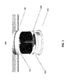
- FIG. 1 is an illustration I 00 of an exemplary downlight luminaire 102 configured for installation in a carveout area 104 of a substantially flat member, such as a ceiling I 06.
- the ceiling 106 may be associated with an office, a retail location, or similar environment.
- the luminaire 102 includes an exemplary mounting mechanism 108 constructed in accordance with an embodiment of the present invention.
- the mounting mechanism 108 assists the installation process and improves ease of installation of the luminaire 102 into the ceiling 106.
- the exemplary mechanism 108 simplifies the installation process and reduces the risk of injury while installing recessed fixtures through the ceiling carveout 104. This approach facilitates faster and more efficient installation of recessed lighting fixtures.
- the luminaire 102 can be easily inserted into the ceiling carveout 104 with a single forward motion occurring in only one direction.
- the installer is not required to push the luminaire in one direction for insertion through a carveout, and then pull it in another direction to lock the luminaire into place, as required, using conventional approaches.
- the mounting mechanism 108 also simplifies the installation process by eliminating the need for holding springs, or mounting clamps, under tension while inserting the luminaire through the carveout 104. In this manner, the risk of injury to an installer is substantially reduced.
- FIG. 2 is a more detailed illustration 200 of the luminaire system 102 and the mounting mechanism 108 depicted in FIG. 1 .
- the luminaire system 1 02 includes a bezel 202, along with a housing 204 enclosing electronics, such as an infusion module and optics (not shown).
- a passive heat sink 206 provides cooling for the infusion module, the optics, and other embedded electronics associated with the luminaire system 102.
- Standard fasteners such as rivets or screws, can be inserted through an opening 208 to fasten the mounting mechanism 108 to the housing 204.
- FIG. 3A is a detailed angular view of the mounting mechanism 108, shown in FIGs. 1 and 2 .
- the mounting mechanism 108 includes a bracket (e.g., base) 300 and an elongated clamp lock 302 slid ably fastened within a pathway 301 of the bracket 300.
- the clamp lock 302 is configured for slidable (i.e., up and down) movement in a lengthwise direction (L) within the pathway 301.
- a lip portion 303 of the clamp lock 302 is provided for locking the luminaire system 102 tightly within the ceiling carveout 104 during installation.
- a spring arm 304A of a spring clamp 304 is positioned in substantially parallel alignment with the clamp lock 302.
- the spring clamp 304 also includes a spring coil 304B attached atop an upper surface of the clamp lock 302 and fastened to the bracket 300 about a pin 306, axially disposed through the spring coil 304B.
- the embodiments of the present invention are not limited to the spring clamp 304 depicted in FIGs 2-3 .
- Other suitable spring clamp configurations are available, as understood by those of skill in the art, and would be within the spirit and scope of the present invention.
- the pin 306 is attached to sides of the bracket 300 through openings 307 in a widthwise direction (W).
- W widthwise direction
- the spring arm 304A is locked into the substantially parallel arrangement (i.e., vertical position) with the clamp lock 302 via a clamp lock top portion 302B.
- FIG. 3B provides an exploded view of the mounting mechanism 108 of FIG. 3A , along with more detailed views of the bracket 300, the clamp lock 302, and the clamp lock top portion 302B, the lip 303, the spring clamp 304, the spring arm 304A, and the spring coil 304B.
- FIG. 4A is an illustration of the mounting mechanism 108, attached to the housing 204, prior to installation of the luminaire 102 through the ceiling carveout 104.
- the spring arm 304A Before installation, the spring arm 304A is in locked substantially vertical alignment with the clamp lock top portion 302B, as shown.
- a distance 400 separates the lip portion 303 from a bottom surface 402 of the ceiling 106.
- FIG. 4B is a more detailed illustration of the mounting mechanism 108, shown in of FIG. 4A , prior to installation.
- the locked vertical alignment between the spring arm 304A and the clamp lock top portion 302B are more clearly visible.
- the mounting mechanism 108 provides a more stable installation of the luminaire system 102 within the carveout area 104. To facilitate installation and installer need only position the luminaire system 102 within the carveout area 104 and gently apply pressure to the luminaire 102 in a vertical direction (V) to facilitate its secure positioning.
- V vertical direction
- FIG. 5A is an illustration of the mounting mechanism 108, after installation of the luminaire system 102 in the ceiling carveout 104, in accordance with the illustrious embodiments.
- V vertical direction
- the entire mounting mechanism 108 moves vertically until the distance 400 decreases to 0.
- the gap 400 disappears when the lip 303 contacts (i.e., hooks onto) the bottom surface 402 of the ceiling 106.
- the lip portion 303 can be released, or pushed by use of an installer's finger. Such a release could become necessary, for example, if one or more surfaces of the ceiling 106 is deformed or otherwise irregular, or if the edge of the ceiling 106 are not sharp enough to activate the mounting mechanism 108.
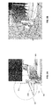
- FIG. 58 is a more detailed illustration of the spring arm 304 released to press against the top surface 501 of the ceiling 106 to secure the installation of the luminaire 102.
- FIG. 6A is an illustration of the mounting mechanism 108, attached to the housing 204, during an exemplary locking step 601.
- an installer may lock the mounting mechanism 1 08, in preparation for installation, by rotating the clamp spring 304 up to vertical position beyond clamp lock 302, in step 601.
- Step 601 prepares the luminaire 102 for insertion through the ceiling carveout 104.
- FIG. 68 is an illustration of exemplary stages occurring during installation of the luminaire 102 (attached to the housing 204) through the carveout 104.
- an installer need only push the luminaire 102 in a vertical direction (V), as indicated by the arrow.
- the clamp lock 302 prevents the spring arm 304A from being released during positioning. More particularly, as depicted in stage 604, the spring arm 304A is prevented from being released until the lip 303 contacts the bottom surface 402 of ceiling 106.
- the spring arm 304A When the vertical movement of the luminaire 102 causes the spring arm 304A to extend vertically beyond a height of the clamp lock top portion 3028, as depicted at stage 606, the spring arm 304A is released. Upon release, the spring arm 304A rotates in a direction towards the top surface 501, as depicted in stage 606. The release of the spring arm 304A occurs as a result of tension created moment within the spring coil 304B. Thus, when the spring arm 304A is released, spring tension is applied to the top surface 501 of the ceiling 106 to complete positioning of the luminaire 102, as depicted at stage 608. This tension continues to pull the entire luminaire system 102, in the vertical direction (V), securing it into a stable position.
- V vertical direction
Landscapes
- Engineering & Computer Science (AREA)
- General Engineering & Computer Science (AREA)
- Non-Portable Lighting Devices Or Systems Thereof (AREA)
- Fastening Of Light Sources Or Lamp Holders (AREA)
Abstract
Description
- The present invention generally relates to installation of lighting fixtures, or luminaires. More particularly, the present invention relates to mechanisms for mounting luminaire systems in locations, such as ceilings, in a safe, efficient, and cost-effective manner.
- Luminaires are increasingly relied upon for white light production in downlight high-ceiling applications. These applications provide lighting for offices, retail space settings, and other commercial applications. Additionally, more recently developed downlight luminaires also include advanced lighting technology that is inherently more sustainable, while providing significant energy savings than predecessor, or legacy systems.
- High-ceiling luminaire applications, however, are generally associated with inherent maintenance inefficiencies. For example, in addition to costs associated with lamp replacement, lifts and scaffolding are usually required to safely perform installation and maintenance for high-ceiling luminaires. These installation and maintenance challenges are further complicated because many of these luminaires are recessed and simply difficult to install or remove.
- To assist the installation process, many conventional downlight luminaires include sheet-metal fixing springs on opposing sides of the luminaire for recessed installations through carveouts in the ceiling. These conventional luminaires, however, have several shortcomings. During installation, as one example, installers must use their fingers to hold the springs under tension, while inserting the luminaire through the carveout. Such designs can present a risk of injury to the installer and can actually make the installation process more complicated.
- Given the aforementioned deficiencies, a need exists for mounting systems and methods to improve the ease of installation of luminaires, and other recessed fixtures, into a ceiling, wall, or into some other substantially flat member.
- In certain circumstances, an embodiment of the present invention includes a device including a base configured for attachment to a lighting fixture. The device also includes an engagement mechanism having first and second portions configured for mounting the lighting fixture within a recess of a substantially flat member having first and second ends. The engagement mechanism facilitates movement of the lighting fixture within the recess from the first end towards the second end, the movement (i) being responsive to an applied force and (ii) occurring in only a single direction. The first portion engages a first surface of the member and the second portion engages a second surface of the member when the lighting fixture reaches the second end.
- Exemplary embodiments of the present invention include a luminaire mounting mechanism for improving ease of installation of the luminaire into the ceiling. For example, the luminaire can be easily inserted into the ceiling with a single forward motion in only one direction. Thus, the need for pushing and pulling the luminaire in multiple directions, during installation, completely eliminated. Such an approach simplifies the installation process and minimizes risk of injury while installing recessed fixtures through a ceiling carveout.
- More specifically, mounting systems constructed in accordance with the embodiments allow installators greater freedom of movement, during installation. This enhanced freedom of movement is provided by eliminating the need to hold fixing springs under tension during insertion of the luminaire into the ceiling. This approach also helps to avoid possible injury to fingers when mounting clamps are used to pull the fixture up to the ceiling carveout. Additionally, components constructed in accordance with the embodiments can be formed of simple geometry, avoiding the use of complex shapes or technologies.
- Further features and advantages of the invention, as well as the structure and operation of various embodiments of the invention, are described in detail below with reference to the accompanying drawings. It is noted that the invention is not limited to the specific embodiments described herein. Such embodiments are presented herein for illustrative purposes only. Additional embodiments will be apparent to persons skilled in the relevant art(s) based on the teachings contained herein.
-
-
FIG. 1 is an illustration of an exemplary downlight luminaire and mounting mechanism system constructed in accordance with an embodiment of the present invention; -
FIG. 2 is a more detailed illustration of the luminaire system and mounting mechanism depicted inFIG. 1 ; -
FIG. 3A is a detailed illustration of the mounting mechanism depicted inFIGs. 1 and2 in accordance with the embodiments; -
FIG. 3B is an exploded view of the mounting mechanism illustrated inFIG. 3A ; -
FIG. 4A is an illustration of the mounting mechanism ofFIG. 2 prior to installation in a ceiling carveout; -
FIG. 4B is a more detailed illustration of the mounting mechanism ofFIG. 4A prior to installation; -
FIG. 5A is an illustration of the mounting mechanism ofFIG. 4A , after installation in the ceiling carveout, in accordance with the embodiments; -
FIG. 5B is a more detailed illustration of the mounting mechanism ofFIG. 4B after installation; -
FIG. 6A is an illustration of a mounting mechanism attached to housing, during an exemplary locking step; and -
FIG. 6B is an illustration of exemplary stages occurring during installation of the luminaire into the ceiling through the carveout. - The present invention may take form in various components and arrangements of components, and in various process operations and arrangements of process operations. The present invention is illustrated in the accompanying drawings, throughout which, like reference numerals may indicate corresponding or similar parts in the various figures. The drawings are only for the purposes of illustrated preferred embodiments and are not to be construed as limiting the invention. Given the following enabling description of the drawings, the novel aspects of the present invention should become evident to a person of ordinary skill in the art.
- While illustrative embodiments are described herein with illustrative embodiments for particular implementations, it should be understood that the invention is not limited thereto. Those skilled in the art with access to the teachings provided herein will recognize additional modifications, applications, and embodiments within the scope thereof, and additional fields in which the lighting systems described herein would be of significant utility.
- The following detailed description is merely exemplary in nature and is not intended to limit the applications and uses disclosed herein. Further, there is no intention to be bound by any theory presented in the preceding background or summary or the following detailed description.
-
FIG. 1 is an illustration I 00 of anexemplary downlight luminaire 102 configured for installation in acarveout area 104 of a substantially flat member, such as a ceiling I 06. As noted above, theceiling 106 may be associated with an office, a retail location, or similar environment. Theluminaire 102 includes anexemplary mounting mechanism 108 constructed in accordance with an embodiment of the present invention. - The mounting
mechanism 108, discussed in greater detail below, assists the installation process and improves ease of installation of theluminaire 102 into theceiling 106. Theexemplary mechanism 108 simplifies the installation process and reduces the risk of injury while installing recessed fixtures through theceiling carveout 104. This approach facilitates faster and more efficient installation of recessed lighting fixtures. - In the exemplary embodiment of
FIG. 1 , theluminaire 102 can be easily inserted into theceiling carveout 104 with a single forward motion occurring in only one direction. The installer is not required to push the luminaire in one direction for insertion through a carveout, and then pull it in another direction to lock the luminaire into place, as required, using conventional approaches. - The mounting
mechanism 108 also simplifies the installation process by eliminating the need for holding springs, or mounting clamps, under tension while inserting the luminaire through thecarveout 104. In this manner, the risk of injury to an installer is substantially reduced. -
FIG. 2 is a moredetailed illustration 200 of theluminaire system 102 and the mountingmechanism 108 depicted inFIG. 1 . By way of background, theluminaire system 1 02 includes abezel 202, along with ahousing 204 enclosing electronics, such as an infusion module and optics (not shown). - A
passive heat sink 206 provides cooling for the infusion module, the optics, and other embedded electronics associated with theluminaire system 102. Standard fasteners, such as rivets or screws, can be inserted through anopening 208 to fasten themounting mechanism 108 to thehousing 204. -
FIG. 3A is a detailed angular view of the mountingmechanism 108, shown inFIGs. 1 and2 . InFIG. 3A , the mountingmechanism 108 includes a bracket (e.g., base) 300 and anelongated clamp lock 302 slid ably fastened within apathway 301 of thebracket 300. For example, theclamp lock 302 is configured for slidable (i.e., up and down) movement in a lengthwise direction (L) within thepathway 301. Alip portion 303 of theclamp lock 302 is provided for locking theluminaire system 102 tightly within theceiling carveout 104 during installation. - A
spring arm 304A of aspring clamp 304 is positioned in substantially parallel alignment with theclamp lock 302. Thespring clamp 304 also includes aspring coil 304B attached atop an upper surface of theclamp lock 302 and fastened to thebracket 300 about apin 306, axially disposed through thespring coil 304B. The embodiments of the present invention are not limited to thespring clamp 304 depicted inFIGs 2-3 . Other suitable spring clamp configurations are available, as understood by those of skill in the art, and would be within the spirit and scope of the present invention. - The
pin 306 is attached to sides of thebracket 300 throughopenings 307 in a widthwise direction (W). Prior to installation of theluminaire system 102, as illustrated more fully below, thespring arm 304A is locked into the substantially parallel arrangement (i.e., vertical position) with theclamp lock 302 via a clamp locktop portion 302B. -
FIG. 3B provides an exploded view of the mountingmechanism 108 ofFIG. 3A , along with more detailed views of thebracket 300, theclamp lock 302, and the clamp locktop portion 302B, thelip 303, thespring clamp 304, thespring arm 304A, and thespring coil 304B. -
FIG. 4A is an illustration of the mountingmechanism 108, attached to thehousing 204, prior to installation of theluminaire 102 through theceiling carveout 104. Before installation, thespring arm 304A is in locked substantially vertical alignment with the clamp locktop portion 302B, as shown. Adistance 400 separates thelip portion 303 from abottom surface 402 of theceiling 106. -
FIG. 4B is a more detailed illustration of the mountingmechanism 108, shown in ofFIG. 4A , prior to installation. InFIG. 4B , the locked vertical alignment between thespring arm 304A and the clamp locktop portion 302B are more clearly visible. As noted above, the mountingmechanism 108 provides a more stable installation of theluminaire system 102 within thecarveout area 104. To facilitate installation and installer need only position theluminaire system 102 within thecarveout area 104 and gently apply pressure to theluminaire 102 in a vertical direction (V) to facilitate its secure positioning. -
FIG. 5A is an illustration of the mountingmechanism 108, after installation of theluminaire system 102 in theceiling carveout 104, in accordance with the illustrious embodiments. After the installer applies pressure in the vertical direction (V), as discussed above, theentire mounting mechanism 108 moves vertically until thedistance 400 decreases to 0. Thegap 400 disappears when thelip 303 contacts (i.e., hooks onto) thebottom surface 402 of theceiling 106. - When contact is established between the
lip 303 and thebottom surface 402, as the luminaire moves in the vertical direction (V), thebracket 300 and thespring arm 304A continue to move vertically. During this vertical movement, theclamp lock 302 remains in the vertically locked position. - As the
bracket 300 and thespring arm 304 continue moving vertically, a tip of thespring arm 304A eventually rises above the clamp locktop portion 302B, releasing the locked position of thespring arm 304A. Tension within thespring coil 304B releases the locked vertical alignment, forcing thespring arm 304A to press against atop surface 501 of theceiling 106. This process is illustrated withreference character 502 ofFIG. 5A . - As discussed above, the
lip portion 303 can be released, or pushed by use of an installer's finger. Such a release could become necessary, for example, if one or more surfaces of theceiling 106 is deformed or otherwise irregular, or if the edge of theceiling 106 are not sharp enough to activate themounting mechanism 108. - FIG. 58 is a more detailed illustration of the
spring arm 304 released to press against thetop surface 501 of theceiling 106 to secure the installation of theluminaire 102. -
FIG. 6A is an illustration of the mountingmechanism 108, attached to thehousing 204, during anexemplary locking step 601. Prior to installation, an installer may lock themounting mechanism 1 08, in preparation for installation, by rotating theclamp spring 304 up to vertical position beyondclamp lock 302, instep 601. Step 601 prepares theluminaire 102 for insertion through theceiling carveout 104. - FIG. 68 is an illustration of exemplary stages occurring during installation of the luminaire 102 (attached to the housing 204) through the
carveout 104. For example, in positioning stages 602 and 604, after theluminaire 102 is inserted through thecarveout 104, an installer need only push theluminaire 102 in a vertical direction (V), as indicated by the arrow. As the installer continues to push theluminaire 102, positioning it forward in the vertical direction (V), theclamp lock 302 prevents thespring arm 304A from being released during positioning. More particularly, as depicted instage 604, thespring arm 304A is prevented from being released until thelip 303 contacts thebottom surface 402 ofceiling 106. - When the vertical movement of the
luminaire 102 causes thespring arm 304A to extend vertically beyond a height of the clamp lock top portion 3028, as depicted atstage 606, thespring arm 304A is released. Upon release, thespring arm 304A rotates in a direction towards thetop surface 501, as depicted instage 606. The release of thespring arm 304A occurs as a result of tension created moment within thespring coil 304B. Thus, when thespring arm 304A is released, spring tension is applied to thetop surface 501 of theceiling 106 to complete positioning of theluminaire 102, as depicted atstage 608. This tension continues to pull theentire luminaire system 102, in the vertical direction (V), securing it into a stable position. - Those skilled in the art, particularly in light of the foregoing teachings, may make alternative embodiments, examples, and modifications that would still be encompassed by the technology. Further, it should be understood that the terminology used to describe the technology is intended to be in the nature of words of description rather than of limitation.
- Those skilled m the art will also appreciate that various adaptations and modifications of the preferred and alternative embodiments described above can be configured without departing from the scope and spirit of the technology. Therefore, it is to be understood that, within the scope of the appended claims, the invention may be practiced other than as specifically described herein.
- Various aspects and embodiments of the present invention are defined by the following numbered clauses:
- 1. A device for mounting a lighting fixture within a recess of a substantially flat member, comprising:
- a bracket (i) having a pathway formed of a bottom and two sides and (ii) configured for attachment to the lighting fixture;
- a locking mechanism (i) having a lip portion and (ii) configured for slidable movement in only one direction within the pathway in response to an applied force; and
- a tension mechanism positioned in substantially parallel alignment with the locking mechanism;
- wherein when the force is applied, the is tension mechanism engages a first surface of the substantially flat member and the lip portion engages a second surface thereof.
- 2. The device of
clause 1, wherein the lighting fixture is a recessed luminaire. - 3. The device of clause 2, wherein the substantially flat member includes at least one from the group including a ceiling and a wall.
- 4. The device of
clause 1 or 2, wherein the bracket is attached to an exterior surface of the lighting fixture. - 5. The device of clause 4, wherein the tension mechanism includes at least one from the group including a coil, a machined spring, and a flat spring.
Claims (15)
- A device, comprising:an engagement mechanism (108) having first and second portions (304,303) configured for mounting a lighting fixture (102) within a recess (104) of a substantially flat member (106) having first and second ends;wherein the engagement mechanism (108) facilitates movement of the lighting fixture (102) within the recess (104) from the first end to the second end, the movement (i) being responsive to an applied force and (ii) occurring in only a single direction; andwherein the first portion (304) engages a first surface of the member (106) and the second portion (303) engages a second surface of the member (106) when the lighting fixture (102) reaches the second end.
- The device of claim 1, wherein the force is externally applied, and wherein the first portion is a locking mechanism (302,303).
- The device of claim 2, wherein the second portion (304) is a tension applying mechanism.
- The device of claim 3, wherein the tension applying mechanism (304) includes at least one from the group including a coil, a machined spring, and a flat spring.
- The device of any of claims 1 to 4, wherein the substantially flat member (106) includes at least one from the group including a ceiling and a wall.
- The device of claim 5, where the recess (104) is a carveout area in the ceiling.
- The device of claim 6, wherein the first surface is one side of the ceiling (106) and the second surface is the other side of the ceiling (106).
- The device of any preceding claim, wherein the lighting fixture (102) is a recessed luminaire.
- The device of any preceding claims, wherein the engagement mechanism (108) comprises:a bracket (300) having a pathway (301) formed of a bottom and two sides and configured for attachment to the lighting fixture (102);a locking mechanism (302) having a lip portion and (303) configured for slidable movement in only one direction within the pathway (301) in response to an applied force; anda tension mechanism (304) positioned in substantially parallel alignment with the locking mechanism (302);wherein when the force is applied, the is tension mechanism (304) engages a first surface of the substantially flat member (106) and the lip portion (303) engages a second surface thereof.
- The device of claim 9, wherein the bracket (300) is attached to an exterior surface of the lighting fixture (102).
- A method for mounting a lighting fixture (102) within a recess (104) of a substantially flat member (106), comprising:inserting the lighting fixture (102) in a first end of the recess (104), the lighting fixture (102) having a bracket (300) attached to an exterior surface thereof, the bracket (300) having a pathway (301) formed of a bottom and two sides and configured for attachment to the lighting fixture (102);wherein a locking mechanism (302) is configured for slidable movement in only one direction within the pathway (301), the locking mechanism having a lip portion (303) and configured for slidable movement in only one direction within the pathway (301) in response to an applied force; andwherein a tension mechanism (304) is positioned in a substantially parallel alignment with the locking mechanism (302); and applying an external force to move the lighting fixture (102) from the first and to a second end of the recess (104);
wherein when the force is applied, the tension mechanism (304) engages a first surface of the substantially flat member (106) and the lip portion (303) engages a second surface thereof. - The method of claim 11, wherein the lighting fixture is a recessed luminaire.
- The method of claim 12, wherein the substantially flat member includes at least one from the group including a ceiling and a wall.
- The method of claim 13, wherein the bracket is attached to an external surface of the lighting fixture.
- The method of claim 14, wherein the tension mechanism is formed of at least one from the group including a coil, a machined spring, and a flat spring.
Applications Claiming Priority (1)
| Application Number | Priority Date | Filing Date | Title |
|---|---|---|---|
| US14/278,897 US9732946B2 (en) | 2014-05-15 | 2014-05-15 | Luminaire ceiling mounting mechanism |
Publications (1)
| Publication Number | Publication Date |
|---|---|
| EP2944870A1 true EP2944870A1 (en) | 2015-11-18 |
Family
ID=53188897
Family Applications (1)
| Application Number | Title | Priority Date | Filing Date |
|---|---|---|---|
| EP15167640.0A Withdrawn EP2944870A1 (en) | 2014-05-15 | 2015-05-13 | Luminaire ceiling mounting mechanism |
Country Status (3)
| Country | Link |
|---|---|
| US (1) | US9732946B2 (en) |
| EP (1) | EP2944870A1 (en) |
| CN (1) | CN105889824A (en) |
Cited By (2)
| Publication number | Priority date | Publication date | Assignee | Title |
|---|---|---|---|---|
| WO2019174950A1 (en) * | 2018-03-15 | 2019-09-19 | Signify Holding B.V. | A lamp for mounting in an opening through a planar substrate, and an installation method |
| AU2017218994B2 (en) * | 2016-08-24 | 2021-08-26 | Swarm Holdings Llc | Speaker mount and assembly and method of disengagement thereof |
Families Citing this family (11)
| Publication number | Priority date | Publication date | Assignee | Title |
|---|---|---|---|---|
| US10018336B2 (en) * | 2015-07-07 | 2018-07-10 | GE Lighting Solutions, LLC | Engagement mechanism and method for mounting lighting fixture |
| US10344952B2 (en) * | 2016-05-24 | 2019-07-09 | Georgi Yosifov Georgiev | Recessed light-emitting diode lighting fixture |
| US10253960B2 (en) * | 2016-12-15 | 2019-04-09 | GE Lighting Solutions, LLC | Retainer apparatus for luminaire assembly |
| US10125959B2 (en) * | 2017-01-27 | 2018-11-13 | Brandon Cohen | Ceiling triggered spring clip for lighting module install |
| CN106949412B (en) * | 2017-04-25 | 2025-04-15 | 漳州立达信光电子科技有限公司 | Downlight fixing structure |
| WO2019061061A1 (en) * | 2017-09-27 | 2019-04-04 | 佛山市威得士灯饰电器有限公司 | Downlight with automatic mounting device |
| GB201818840D0 (en) * | 2018-11-19 | 2019-01-02 | Native Design Ltd | Mounting system and method |
| US10816173B2 (en) | 2018-12-31 | 2020-10-27 | Luminii | Mounting brackets |
| USD886569S1 (en) | 2018-12-31 | 2020-06-09 | Luminii | Mounting bracket |
| USD899898S1 (en) | 2018-12-31 | 2020-10-27 | Luminii | Mounting bracket |
| GB2591791B (en) * | 2020-02-06 | 2023-06-14 | Smith Danny | A collar for a recessed fixture |
Citations (4)
| Publication number | Priority date | Publication date | Assignee | Title |
|---|---|---|---|---|
| JP2870636B1 (en) * | 1998-02-05 | 1999-03-17 | 大光電機株式会社 | Mounting equipment for ceiling-mounted lighting fixtures |
| DE102007036979A1 (en) * | 2007-05-03 | 2008-11-06 | Zumtobel Lighting Gmbh | Fastening element for a recessed luminaire |
| EP2314914A1 (en) * | 2009-10-21 | 2011-04-27 | Zumtobel Lighting GmbH | Fitting device for a recessed luminaire |
| DE202013008171U1 (en) * | 2012-09-22 | 2013-09-30 | Theben Ag | Holding device for ceiling mounting devices |
Family Cites Families (23)
| Publication number | Priority date | Publication date | Assignee | Title |
|---|---|---|---|---|
| GB1016256A (en) * | 1962-01-05 | 1966-01-05 | Ass Elect Ind | Improvements relating to electric lighting fittings |
| AU411004B2 (en) | 1969-05-21 | 1971-03-05 | Greendale Engineering & Cables Pty. Limited | Improved support means for recessed light fittings |
| US4039822A (en) * | 1976-05-05 | 1977-08-02 | Lightolier Incorporated | Circular recessed lighting fixture |
| US4088293A (en) * | 1976-06-07 | 1978-05-09 | Erico Products, Inc. | Lay-in light fixture retainer clip |
| JPS5745712U (en) | 1980-08-29 | 1982-03-13 | ||
| US4685037A (en) * | 1984-11-29 | 1987-08-04 | Cooper Industries, Inc. | Spring loaded recessed lighting fixture thermal protection |
| ATE105623T1 (en) * | 1989-06-27 | 1994-05-15 | Emi Plc Thorn | FIXING DEVICE FOR A LAMP. |
| US5068772A (en) * | 1990-08-30 | 1991-11-26 | Troy Lighting, Inc. | Recessed lighting fixture |
| DE4104727C1 (en) * | 1991-02-15 | 1992-08-27 | Herner Glas Bernd Hoffbauer Gmbh & Co Leuchten- Und Industrieglas Kg, 4690 Herne, De | |
| US5377088A (en) * | 1993-03-03 | 1994-12-27 | Lecluze; Michel | Light fixture for mounting to a ceiling, wall or the like |
| DE29504730U1 (en) | 1994-12-09 | 1996-04-18 | Zumtobel Licht Gmbh, Dornbirn | Recessed luminaire |
| US5567041A (en) * | 1995-08-14 | 1996-10-22 | Slocum; Karl | Self supporting recessed ceiling fixture |
| DE19715068A1 (en) * | 1997-04-11 | 1998-10-22 | Erco Leuchten | Recessed luminaire |
| US6000818A (en) * | 1998-10-19 | 1999-12-14 | Canlyte Inc. | Mounting clip for a recessed light fixture |
| ITMI20040515A1 (en) * | 2004-03-18 | 2004-06-18 | Reggiani Illuminazione | SUPPORT DEVICE FOR A LIGHTING APPARATUS |
| CN200968569Y (en) * | 2006-05-31 | 2007-10-31 | 通用电气公司 | Embedded lamp fixed device and installation apparatus thereof |
| CN2919018Y (en) * | 2006-06-26 | 2007-07-04 | 黄儒成 | An adjustable ceiling bracket embedded ceiling lamp |
| CN200982594Y (en) * | 2006-11-14 | 2007-11-28 | 吴育林 | Easy-to-mount ceiling hole lamp |
| US20100039829A1 (en) * | 2008-08-12 | 2010-02-18 | Ge Investment Co., Ltd. | Light-emitting diode lamp |
| US8079727B2 (en) * | 2010-03-24 | 2011-12-20 | Skynet Electronic Co., Ltd. | Recessed lamp support structure |
| WO2012088721A1 (en) | 2010-12-31 | 2012-07-05 | Wu Liangju | Embedded ceiling lamp with radiating space |
| CN103017110B (en) * | 2012-09-19 | 2014-03-05 | 浙江捷莱照明有限公司 | Ceiling fixing fastener assembly for LED (Light Emitting Diode) lamp |
| US9052101B1 (en) * | 2013-08-29 | 2015-06-09 | Cooper Technologies Company | Retrofit mounting device for open frame ceiling |
-
2014
- 2014-05-15 US US14/278,897 patent/US9732946B2/en not_active Expired - Fee Related
-
2015
- 2015-05-13 EP EP15167640.0A patent/EP2944870A1/en not_active Withdrawn
- 2015-05-15 CN CN201510247374.8A patent/CN105889824A/en active Pending
Patent Citations (4)
| Publication number | Priority date | Publication date | Assignee | Title |
|---|---|---|---|---|
| JP2870636B1 (en) * | 1998-02-05 | 1999-03-17 | 大光電機株式会社 | Mounting equipment for ceiling-mounted lighting fixtures |
| DE102007036979A1 (en) * | 2007-05-03 | 2008-11-06 | Zumtobel Lighting Gmbh | Fastening element for a recessed luminaire |
| EP2314914A1 (en) * | 2009-10-21 | 2011-04-27 | Zumtobel Lighting GmbH | Fitting device for a recessed luminaire |
| DE202013008171U1 (en) * | 2012-09-22 | 2013-09-30 | Theben Ag | Holding device for ceiling mounting devices |
Cited By (4)
| Publication number | Priority date | Publication date | Assignee | Title |
|---|---|---|---|---|
| AU2017218994B2 (en) * | 2016-08-24 | 2021-08-26 | Swarm Holdings Llc | Speaker mount and assembly and method of disengagement thereof |
| EP3288280B1 (en) * | 2016-08-24 | 2022-05-18 | Swarm Holdings LLC | Mount assembly and method of disengagement thereof |
| WO2019174950A1 (en) * | 2018-03-15 | 2019-09-19 | Signify Holding B.V. | A lamp for mounting in an opening through a planar substrate, and an installation method |
| US11054119B2 (en) | 2018-03-15 | 2021-07-06 | Signify Holding B.V. | Lamp for mounting in an opening through a planar substrate, and an installation method |
Also Published As
| Publication number | Publication date |
|---|---|
| US20150330611A1 (en) | 2015-11-19 |
| CN105889824A (en) | 2016-08-24 |
| US9732946B2 (en) | 2017-08-15 |
Similar Documents
| Publication | Publication Date | Title |
|---|---|---|
| US9732946B2 (en) | Luminaire ceiling mounting mechanism | |
| US9239131B1 (en) | Adjustable hanger bars with detachment stop | |
| US8474774B2 (en) | Panel component holder | |
| US20170167672A1 (en) | Lighting assembly with light fixture mounted in electrical box | |
| US10018336B2 (en) | Engagement mechanism and method for mounting lighting fixture | |
| US10222013B2 (en) | Luminaire, assembly for a grid ceiling, method for installing a luminaire, method for removing a luminaire, and removal tool | |
| US9739455B2 (en) | LED light engines | |
| EP2997303B1 (en) | Housing for securing a recessed fixture. | |
| EP3500793B1 (en) | Retrofit led light panel | |
| JP2015138784A (en) | Light fixture, lamp, support at light fixture, support element at lamp, and lamp holder and lamp socket | |
| US9169983B2 (en) | Overhead light fixture and related method | |
| US9341349B1 (en) | Systems, methods, and devices for providing a torsion spring bracket assembly for use in cylindrical luminaire housings | |
| WO2017088356A1 (en) | Wall-mounting device for display device and display device | |
| EP3115686A1 (en) | Engagement system and method for mounting lighting fixture | |
| EP2659179B1 (en) | Attachment means, light fittings, use of a roller-type spring and a method for mounting of light fittings | |
| US20130322093A1 (en) | Light apparatus trim wireform | |
| JP2016213095A (en) | Spring member and luminaire | |
| CN104235778B (en) | Light fixture and its mounting seat | |
| KR101032649B1 (en) | Recessed led luminaires | |
| EP3557120A1 (en) | Lighting device | |
| KR101033942B1 (en) | Fixtures for ceiling recessed luminaires | |
| US8844232B1 (en) | Ceiling mount system | |
| CN103162251B (en) | Fixing device and the Down lamp with the fixing device | |
| JP2014154319A (en) | Lighting fixture | |
| EP3382276A1 (en) | Light |
Legal Events
| Date | Code | Title | Description |
|---|---|---|---|
| PUAI | Public reference made under article 153(3) epc to a published international application that has entered the european phase |
Free format text: ORIGINAL CODE: 0009012 |
|
| AK | Designated contracting states |
Kind code of ref document: A1 Designated state(s): AL AT BE BG CH CY CZ DE DK EE ES FI FR GB GR HR HU IE IS IT LI LT LU LV MC MK MT NL NO PL PT RO RS SE SI SK SM TR |
|
| AX | Request for extension of the european patent |
Extension state: BA ME |
|
| 17P | Request for examination filed |
Effective date: 20160518 |
|
| RBV | Designated contracting states (corrected) |
Designated state(s): AL AT BE BG CH CY CZ DE DK EE ES FI FR GB GR HR HU IE IS IT LI LT LU LV MC MK MT NL NO PL PT RO RS SE SI SK SM TR |
|
| STAA | Information on the status of an ep patent application or granted ep patent |
Free format text: STATUS: EXAMINATION IS IN PROGRESS |
|
| 17Q | First examination report despatched |
Effective date: 20171102 |
|
| STAA | Information on the status of an ep patent application or granted ep patent |
Free format text: STATUS: THE APPLICATION IS DEEMED TO BE WITHDRAWN |
|
| 18D | Application deemed to be withdrawn |
Effective date: 20190807 |