EP2944808B1 - Generator für staudruckturbine und staudruckturbine - Google Patents
Generator für staudruckturbine und staudruckturbine Download PDFInfo
- Publication number
- EP2944808B1 EP2944808B1 EP15001484.3A EP15001484A EP2944808B1 EP 2944808 B1 EP2944808 B1 EP 2944808B1 EP 15001484 A EP15001484 A EP 15001484A EP 2944808 B1 EP2944808 B1 EP 2944808B1
- Authority
- EP
- European Patent Office
- Prior art keywords
- generator
- turbine
- ram air
- exciter
- air turbine
- Prior art date
- Legal status (The legal status is an assumption and is not a legal conclusion. Google has not performed a legal analysis and makes no representation as to the accuracy of the status listed.)
- Active
Links
Images


Classifications
-
- B—PERFORMING OPERATIONS; TRANSPORTING
- B64—AIRCRAFT; AVIATION; COSMONAUTICS
- B64D—EQUIPMENT FOR FITTING IN OR TO AIRCRAFT; FLIGHT SUITS; PARACHUTES; ARRANGEMENT OR MOUNTING OF POWER PLANTS OR PROPULSION TRANSMISSIONS IN AIRCRAFT
- B64D41/00—Power installations for auxiliary purposes
- B64D41/007—Ram air turbines
-
- F—MECHANICAL ENGINEERING; LIGHTING; HEATING; WEAPONS; BLASTING
- F01—MACHINES OR ENGINES IN GENERAL; ENGINE PLANTS IN GENERAL; STEAM ENGINES
- F01D—NON-POSITIVE DISPLACEMENT MACHINES OR ENGINES, e.g. STEAM TURBINES
- F01D15/00—Adaptations of machines or engines for special use; Combinations of engines with devices driven thereby
- F01D15/10—Adaptations for driving, or combinations with, electric generators
-
- F—MECHANICAL ENGINEERING; LIGHTING; HEATING; WEAPONS; BLASTING
- F01—MACHINES OR ENGINES IN GENERAL; ENGINE PLANTS IN GENERAL; STEAM ENGINES
- F01D—NON-POSITIVE DISPLACEMENT MACHINES OR ENGINES, e.g. STEAM TURBINES
- F01D15/00—Adaptations of machines or engines for special use; Combinations of engines with devices driven thereby
- F01D15/12—Combinations with mechanical gearing
-
- F—MECHANICAL ENGINEERING; LIGHTING; HEATING; WEAPONS; BLASTING
- F03—MACHINES OR ENGINES FOR LIQUIDS; WIND, SPRING, OR WEIGHT MOTORS; PRODUCING MECHANICAL POWER OR A REACTIVE PROPULSIVE THRUST, NOT OTHERWISE PROVIDED FOR
- F03D—WIND MOTORS
- F03D15/00—Transmission of mechanical power
- F03D15/10—Transmission of mechanical power using gearing not limited to rotary motion, e.g. with oscillating or reciprocating members
-
- F—MECHANICAL ENGINEERING; LIGHTING; HEATING; WEAPONS; BLASTING
- F03—MACHINES OR ENGINES FOR LIQUIDS; WIND, SPRING, OR WEIGHT MOTORS; PRODUCING MECHANICAL POWER OR A REACTIVE PROPULSIVE THRUST, NOT OTHERWISE PROVIDED FOR
- F03D—WIND MOTORS
- F03D9/00—Adaptations of wind motors for special use; Combinations of wind motors with apparatus driven thereby; Wind motors specially adapted for installation in particular locations
- F03D9/20—Wind motors characterised by the driven apparatus
- F03D9/25—Wind motors characterised by the driven apparatus the apparatus being an electrical generator
-
- F—MECHANICAL ENGINEERING; LIGHTING; HEATING; WEAPONS; BLASTING
- F03—MACHINES OR ENGINES FOR LIQUIDS; WIND, SPRING, OR WEIGHT MOTORS; PRODUCING MECHANICAL POWER OR A REACTIVE PROPULSIVE THRUST, NOT OTHERWISE PROVIDED FOR
- F03D—WIND MOTORS
- F03D9/00—Adaptations of wind motors for special use; Combinations of wind motors with apparatus driven thereby; Wind motors specially adapted for installation in particular locations
- F03D9/30—Wind motors specially adapted for installation in particular locations
- F03D9/32—Wind motors specially adapted for installation in particular locations on moving objects, e.g. vehicles
-
- H—ELECTRICITY
- H02—GENERATION; CONVERSION OR DISTRIBUTION OF ELECTRIC POWER
- H02K—DYNAMO-ELECTRIC MACHINES
- H02K7/00—Arrangements for handling mechanical energy structurally associated with dynamo-electric machines, e.g. structural association with mechanical driving motors or auxiliary dynamo-electric machines
- H02K7/18—Structural association of electric generators with mechanical driving motors, e.g. with turbines
- H02K7/1807—Rotary generators
- H02K7/1823—Rotary generators structurally associated with turbines or similar engines
- H02K7/183—Rotary generators structurally associated with turbines or similar engines wherein the turbine is a wind turbine
-
- H—ELECTRICITY
- H02—GENERATION; CONVERSION OR DISTRIBUTION OF ELECTRIC POWER
- H02K—DYNAMO-ELECTRIC MACHINES
- H02K7/00—Arrangements for handling mechanical energy structurally associated with dynamo-electric machines, e.g. structural association with mechanical driving motors or auxiliary dynamo-electric machines
- H02K7/20—Structural association with auxiliary dynamo-electric machines, e.g. with electric starter motors or exciters
-
- F—MECHANICAL ENGINEERING; LIGHTING; HEATING; WEAPONS; BLASTING
- F03—MACHINES OR ENGINES FOR LIQUIDS; WIND, SPRING, OR WEIGHT MOTORS; PRODUCING MECHANICAL POWER OR A REACTIVE PROPULSIVE THRUST, NOT OTHERWISE PROVIDED FOR
- F03D—WIND MOTORS
- F03D80/00—Details, components or accessories not provided for in groups F03D1/00 - F03D17/00
- F03D80/70—Bearing or lubricating arrangements
-
- F—MECHANICAL ENGINEERING; LIGHTING; HEATING; WEAPONS; BLASTING
- F05—INDEXING SCHEMES RELATING TO ENGINES OR PUMPS IN VARIOUS SUBCLASSES OF CLASSES F01-F04
- F05B—INDEXING SCHEME RELATING TO WIND, SPRING, WEIGHT, INERTIA OR LIKE MOTORS, TO MACHINES OR ENGINES FOR LIQUIDS COVERED BY SUBCLASSES F03B, F03D AND F03G
- F05B2220/00—Application
- F05B2220/30—Application in turbines
- F05B2220/31—Application in turbines in ram-air turbines ("RATS")
-
- F—MECHANICAL ENGINEERING; LIGHTING; HEATING; WEAPONS; BLASTING
- F05—INDEXING SCHEMES RELATING TO ENGINES OR PUMPS IN VARIOUS SUBCLASSES OF CLASSES F01-F04
- F05B—INDEXING SCHEME RELATING TO WIND, SPRING, WEIGHT, INERTIA OR LIKE MOTORS, TO MACHINES OR ENGINES FOR LIQUIDS COVERED BY SUBCLASSES F03B, F03D AND F03G
- F05B2220/00—Application
- F05B2220/70—Application in combination with
- F05B2220/706—Application in combination with an electrical generator
- F05B2220/7068—Application in combination with an electrical generator equipped with permanent magnets
-
- F—MECHANICAL ENGINEERING; LIGHTING; HEATING; WEAPONS; BLASTING
- F05—INDEXING SCHEMES RELATING TO ENGINES OR PUMPS IN VARIOUS SUBCLASSES OF CLASSES F01-F04
- F05B—INDEXING SCHEME RELATING TO WIND, SPRING, WEIGHT, INERTIA OR LIKE MOTORS, TO MACHINES OR ENGINES FOR LIQUIDS COVERED BY SUBCLASSES F03B, F03D AND F03G
- F05B2240/00—Components
- F05B2240/50—Bearings
-
- F—MECHANICAL ENGINEERING; LIGHTING; HEATING; WEAPONS; BLASTING
- F05—INDEXING SCHEMES RELATING TO ENGINES OR PUMPS IN VARIOUS SUBCLASSES OF CLASSES F01-F04
- F05B—INDEXING SCHEME RELATING TO WIND, SPRING, WEIGHT, INERTIA OR LIKE MOTORS, TO MACHINES OR ENGINES FOR LIQUIDS COVERED BY SUBCLASSES F03B, F03D AND F03G
- F05B2240/00—Components
- F05B2240/90—Mounting on supporting structures or systems
- F05B2240/92—Mounting on supporting structures or systems on an airbourne structure
- F05B2240/923—Mounting on supporting structures or systems on an airbourne structure which is a vehicle
-
- F—MECHANICAL ENGINEERING; LIGHTING; HEATING; WEAPONS; BLASTING
- F05—INDEXING SCHEMES RELATING TO ENGINES OR PUMPS IN VARIOUS SUBCLASSES OF CLASSES F01-F04
- F05B—INDEXING SCHEME RELATING TO WIND, SPRING, WEIGHT, INERTIA OR LIKE MOTORS, TO MACHINES OR ENGINES FOR LIQUIDS COVERED BY SUBCLASSES F03B, F03D AND F03G
- F05B2260/00—Function
- F05B2260/40—Transmission of power
- F05B2260/403—Transmission of power through the shape of the drive components
- F05B2260/4031—Transmission of power through the shape of the drive components as in toothed gearing
-
- F—MECHANICAL ENGINEERING; LIGHTING; HEATING; WEAPONS; BLASTING
- F05—INDEXING SCHEMES RELATING TO ENGINES OR PUMPS IN VARIOUS SUBCLASSES OF CLASSES F01-F04
- F05D—INDEXING SCHEME FOR ASPECTS RELATING TO NON-POSITIVE-DISPLACEMENT MACHINES OR ENGINES, GAS-TURBINES OR JET-PROPULSION PLANTS
- F05D2220/00—Application
- F05D2220/30—Application in turbines
- F05D2220/34—Application in turbines in ram-air turbines ("RATS")
-
- Y—GENERAL TAGGING OF NEW TECHNOLOGICAL DEVELOPMENTS; GENERAL TAGGING OF CROSS-SECTIONAL TECHNOLOGIES SPANNING OVER SEVERAL SECTIONS OF THE IPC; TECHNICAL SUBJECTS COVERED BY FORMER USPC CROSS-REFERENCE ART COLLECTIONS [XRACs] AND DIGESTS
- Y02—TECHNOLOGIES OR APPLICATIONS FOR MITIGATION OR ADAPTATION AGAINST CLIMATE CHANGE
- Y02E—REDUCTION OF GREENHOUSE GAS [GHG] EMISSIONS, RELATED TO ENERGY GENERATION, TRANSMISSION OR DISTRIBUTION
- Y02E10/00—Energy generation through renewable energy sources
- Y02E10/70—Wind energy
- Y02E10/72—Wind turbines with rotation axis in wind direction
-
- Y—GENERAL TAGGING OF NEW TECHNOLOGICAL DEVELOPMENTS; GENERAL TAGGING OF CROSS-SECTIONAL TECHNOLOGIES SPANNING OVER SEVERAL SECTIONS OF THE IPC; TECHNICAL SUBJECTS COVERED BY FORMER USPC CROSS-REFERENCE ART COLLECTIONS [XRACs] AND DIGESTS
- Y02—TECHNOLOGIES OR APPLICATIONS FOR MITIGATION OR ADAPTATION AGAINST CLIMATE CHANGE
- Y02E—REDUCTION OF GREENHOUSE GAS [GHG] EMISSIONS, RELATED TO ENERGY GENERATION, TRANSMISSION OR DISTRIBUTION
- Y02E10/00—Energy generation through renewable energy sources
- Y02E10/70—Wind energy
- Y02E10/728—Onshore wind turbines
Definitions
- the present disclosure relates to components of ram air turbines, and more particularly, to generator assemblies for use in ram air turbines.
- Ram air turbines are generally used in aircraft to provide supplemental and/or emergency power to the aircraft by utilizing air flow to rotate a turbine.
- Ram air turbines can provide either electrical or hydraulic power.
- Electrical ram air turbines produce electrical power by transferring the rotation of the turbine to a generator.
- Ram air turbines can be located in the nose of the aircraft. However, in such configurations, the size and configuration of the ram air turbine bay envelope may cause the generator to be located too close to the blades, which can disturb the airflow behind the blades, causing the blades to prematurely fatigue. Therefore, it may be beneficial to provide a more compact generator that shifts the largest diameter section of the generator away from the blade path.
- the present invention provides a ram air turbine in accordance with claim 1.
- a ratio of a distance from the blade to an outer perimeter of the generator to a radius of the generator adapter section of the strut is greater than 3.
- the generator further comprises a generator cover and a generator bearing, and the bearing may engage with and maintain the relative positions of the driveshaft and the generator.
- the generator cover may have a driveshaft pilot diameter and a generator pilot diameter and may have a cone.
- the permanent magnet generator and the exciter are positioned within the cone of the generator cover and within a main stator of the generator.
- the present invention provides a generator for use in a ram air turbine in accordance with claim 9.
- the generator bearing may engage with and maintain the relative positions of a driveshaft and the generator.
- the generator cover has a driveshaft pilot diameter and a generator pilot diameter.
- the permanent magnet generator and the exciter are positioned within a main stator of the generator.
- tail refers to the direction associated with the tail (e.g., the back end) of an aircraft, or generally, to the direction of exhaust of the gas turbine.
- forward refers to the directed associated with the nose (e.g., the front end) of an aircraft, or generally, to the direction of flight or motion.
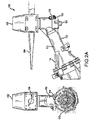
- an aircraft 10 can comprise a nose 12.
- a ram air turbine 100 can be located within nose 12 of aircraft 10, and when needed, ram air turbine 100 can be lowered out of nose 12 and into the path of airflow.
- ram air turbine 100 comprises, a turbine 102 having one or more blades 104.
- Turbine 102 is removably coupled to a strut 110.
- strut 110 can be bolted to the rear of turbine 102.
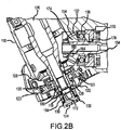
- Strut 110 comprises a gearbox section 116, a drive section 112, and a generator adapter section 114.
- Strut 110 may be a one piece strut, comprising gearbox section 116, drive section 112, and generator adapter section 114 that are all integral to each other.
- turbine 102 may be removably coupled to gearbox section 116 of strut 110.
- Strut 110 may comprise a transition between drive section 112 and generator adapter section 114.
- drive section 112 may have a reduced diameter in relation to generator adapter section 114, such that strut 110 comprises a cone-shaped transition region between drive section 112 and generator adapter section 114.
- the various components of the ram air turbine that transfer rotational force of turbine 102 to a generator are located within gearbox section 116, drive section 112, and generator adapter section 114. As will be further described, many of these components may reside in one or more section of strut 110.
- Gearbox section 116 comprises a turbine shaft 126 and a bevel gear 128.
- Turbine shaft 126 may, for example, be removably coupled to turbine 102, allowing turbine shaft 126 to rotate with the rotation of turbine blades 104.
- Bevel gear 128 may be removably coupled to turbine shaft 126.
- bevel gear 128 may be removably coupled to turbine shaft 126 by a spanner nut, a splined connection, or any other manner of coupling.
- Bevel gear 128 may be oriented perpendicularly to turbine shaft 126.
- bevel gear 128 may comprise a beveled profile configured to interface with another gear and transmit rotation of turbine shaft 126 in a different direction.
- bevel gear 128 can interface with a pinion gear to direct the rotational force of turbine 102 to a generator.
- an opposing end of turbine shaft 126 may be seated in a bearing 120 located within a bearing retainer 123.
- a cover 122 may, for example, be located at an opposite end of gearbox section 116 from turbine 102, and provide a seal for gearbox section 116 against outside contaminants.
- gearbox section 116 also referred to as a gearbox section, comprises lubricating fluid, and cover 122 may retain such fluid within gearbox section 116.
- Cover 122 may, for example, be secured to gearbox section 116 of strut 110 by one or more fasteners such as screws or bolts.
- drive section 112 of strut 110 may comprise a driveshaft 134.
- Driveshaft 134 may traverse drive section 112 and transfer rotation of turbine shaft 126 to generator 140.
- Driveshaft 134 comprises a pinion gear 132.
- pinion gear 132 may comprise a gear body 174 and a gear face 154.
- Gear face 154 may comprise, for example, a gear tooth pattern that is complimentary to the pattern of bevel gear 128.
- Pinion gear 132 engages with bevel gear 128 to transfer rotation of turbine shaft 126 to driveshaft 134.
- Pinion gear 132 may, for example, be secured to driveshaft 134 by a spanner nut.
- pinion gear 132 may comprise a key 160 configured to interact with a keyed joint 162 of driveshaft 134.
- key 160 and keyed joint 162 may maintain the position of pinion gear 132 such that pinion gear 132 does not rotate independently of driveshaft 134.
- any manner of securing pinion gear 132 to driveshaft 134 is within the scope of the present disclosure.
- driveshaft 134 further comprises a pinion bearing 136.
- Pinion bearing 136 may be coupled to pinion gear 132 and facilitate rotation and positioning of pinion bearing 136 within drive section 112 of strut 110.
- Pinion gear 132 may further comprise, for example, a pinion retainer 176.
- Driveshaft 134 may comprise, for example, a hollow shaft with an inner diameter and outer diameter. In other embodiments, driveshaft 134 may comprise a solid shaft.
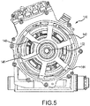
- ram air turbine 100 comprises generator 140 located at least partially within generator adapter section 114 of strut 110.
- the outside diameter of generator adapter section 114 is such that generator adapter section 114 does not interfere with the wake of blades 104 of turbine 102 during operation. Stated another way, the distance from one of blades 104 to the center of generator 140 is at least three times that of a projected radius of generator adapter section 114.
- generator adapter section 114 may be generally free of protrusions, such that the exterior surface is relatively smooth. In such embodiments, the relative smoothness of the exterior surface of generator adapter section 114 may assist in reducing turbulence and blade fatigue.
- Generator 140 comprises, a turbine end 180.
- turbine end 180 is oriented towards driveshaft 134.
- Turbine end 180 is at least partially located within a cone-shaped transition region between drive section 112 and generator adapter section 114 of strut 110.
- Generator 140 comprises a permanent magnet generator 148.
- Permanent magnet generators are typically located above the generator, at the end opposite turbine end 180. When the aircraft envelope is restricted, as is the case with many nose-located ram air turbine applications, locating permanent magnet generator 148 above generator 140 causes the rest of generator 140 to be located closer to the turbine blades.
- permanent magnet generator 148 is positioned at turbine end 180 of generator 140. Further, permanent magnet generator 148 is at least partially surrounded by an exciter 146.
- Permanent magnet generator 148 is partially surrounded by a stator of exciter 146.
- exciter 146 is at least partially surrounded by a main stator 142 of generator 140 to shorten the overall length.
- generator 140 comprises a generator cover 144.
- Generator cover 144 comprises a cone 182 oriented towards drive section 112 and positioned in a transition region between drive section 112 and generator adapter section 114.
- Permanent magnet generator 148 and exciter 146 are located within cone 182 of generator cover 144. In various embodiments, by locating permanent magnet generator 148 and exciter 146 in proximity, both may be wired to a common external connector, and therefore would not require two separate connectors.
- Cone 182 of generator cover 144 can also comprise a generator bearing 150.
- an end of driveshaft 134 engages with generator bearing 150.
- generator bearing 150 provides support to, indexes, and/or maintains the position of an end of driveshaft 134. Any manner of maintaining proper positioning of generator cover 144 and generator bearing 150 is within the scope of the present disclosure.
- generator 140 further comprises an upper generator bearing 198.
- the upper generator bearing 198 may, for example, be positioned concentrically within the main stator 142 of generator 140 to assist in positioning the largest diameter section of generator 140 out of the path of the turbine blades.
- references to "one embodiment,” “an embodiment,” “an example embodiment,” etc. indicate that the embodiment described may include a particular feature, structure, or characteristic, but every embodiment may not necessarily include the particular feature, structure, or characteristic. Moreover, such phrases are not necessarily referring to the same embodiment. Further, when a particular feature, structure, or characteristic is described in connection with an embodiment, it is submitted that it is within the knowledge of one skilled in the art to affect such feature, structure, or characteristic in connection with other embodiments whether or not explicitly described. After reading the description, it will be apparent to one skilled in the relevant art(s) how to implement the disclosure in alternative embodiments.
Landscapes
- Engineering & Computer Science (AREA)
- Power Engineering (AREA)
- Mechanical Engineering (AREA)
- General Engineering & Computer Science (AREA)
- Life Sciences & Earth Sciences (AREA)
- Sustainable Development (AREA)
- Sustainable Energy (AREA)
- Chemical & Material Sciences (AREA)
- Combustion & Propulsion (AREA)
- Aviation & Aerospace Engineering (AREA)
- Connection Of Motors, Electrical Generators, Mechanical Devices, And The Like (AREA)
Claims (12)
- Staudruckturbine (100), umfassend:eine Turbine (102), die eine Laufschaufel (104) umfasst,eine Strebe (110), die abnehmbar mit der Turbine (102) gekoppelt ist und einen Antriebsabschnitt (112), einen Getriebeabschnitt (116) und einen Generatoradapterabschnitt (114) umfasst, wobei der Getriebeabschnitt (116) eine Turbinenwelle (126) und ein Kegelrad (128) umfasst;einen Generator (140), der innerhalb des Generatoradapterabschnitts (114) der Strebe (110) angeordnet ist und eine Turbinenseite (180) umfasst, wobei eine Erregermaschine (146) an der Turbinenseite (180) des Generators (140) angeordnet ist und wobei ein Dauermagnetgenerator (148) zumindest teilweise innerhalb eines Stators der Erregermaschine (146) angeordnet ist, undeine Antriebswelle (134), die ein Ausgleichsrad (132) aufweist, das in das Kegelrad (128) eingreift, wobei die Antriebswelle (134) abnehmbar mit dem Generator (140) gekoppelt ist;wobei die Strebe (110) einen Konus umfasst, der zwischen dem Antriebsabschnitt (112) und dem Generatoradapterabschnitt (114) angeordnet ist, und wobei der Dauermagnetgenerator (148) und die Erregermaschine (146) innerhalb des Konus der Strebe (110) angeordnet sind.
- Staudruckturbine nach Anspruch 1, wobei ein Verhältnis eines Abstands von der Laufschaufel (104) zu einem äußeren Umfang des Generators (140) zu einem projizierten Radius des Generatoradapterabschnitts (114) der Strebe (110) größer als 3 ist.
- Staudruckturbine nach Anspruch 1 oder 2, wobei der Generator (140) ferner eine Generatorabdeckung (144) und ein Generatorlager (150) umfasst.
- Staudruckturbine nach Anspruch 3, wobei das Generatorlager (150) in die Antriebswelle (134) und den Generator (140) eingreift und deren relative Positionen aufrechterhält.
- Staudruckturbine nach Anspruch 3 oder 4, wobei die Generatorabdeckung (144) einen Antriebswellenpilotdurchmesser und einen Generatorpilotdurchmesser aufweist.
- Staudruckturbine nach Anspruch 3, 4 oder 5, wobei die Generatorabdeckung (144) einen Konus (182) umfasst.
- Staudruckturbine nach Anspruch 6, wobei der Dauermagnetgenerator (148) und die Erregermaschine (146) innerhalb des Konus (182) der Generatorabdeckung (144) angeordnet sind.
- Staudruckturbine nach einem der vorstehenden Ansprüche, wobei der Dauermagnetgenerator (148) und die Erregermaschine (146) innerhalb und auf derselben Seite wie ein Hauptstator (142) des Generators (140) angeordnet sind.
- Generator (140) zur Verwendung in einer Staudruckturbine (100), umfassend:eine Erregermaschine (146);einen Dauermagnetgenerator (148);eine Generatorabdeckung (144); undein Generatorlager (150), wobei der Generator (140) eine Turbinenseite (180) umfasst und die Erregermaschine (146) auf der Turbinenseite (180) des Generators (140) angeordnet ist; unddadurch gekennzeichnet, dassder Dauermagnetgenerator (148) innerhalb eines Stators der Erregermaschine (146) angeordnet ist; undder Dauermagnetgenerator (148) und die Erregermaschine (146) innerhalb eines Konus (182) der Generatorabdeckung (144) angeordnet sind.
- Generator nach Anspruch 9, wobei das Generatorlager (150) in die Antriebswelle (134) und den Generator (140) eingreift und deren relative Positionen aufrechterhält.
- Generator nach Anspruch 9 oder 10, wobei die Generatorabdeckung (144) einen Antriebswellenpilotdurchmesser und einen Generatorpilotdurchmesser aufweist.
- Generator nach einem der Ansprüche 9 bis 11, wobei der Dauermagnetgenerator (148) und die Erregermaschine (146) innerhalb eines Hauptstators des Generators (140) angeordnet sind.
Applications Claiming Priority (1)
| Application Number | Priority Date | Filing Date | Title |
|---|---|---|---|
| US14/280,589 US9527600B2 (en) | 2014-05-17 | 2014-05-17 | Ram air turbine generator assemblies |
Publications (2)
| Publication Number | Publication Date |
|---|---|
| EP2944808A1 EP2944808A1 (de) | 2015-11-18 |
| EP2944808B1 true EP2944808B1 (de) | 2019-11-13 |
Family
ID=53188846
Family Applications (1)
| Application Number | Title | Priority Date | Filing Date |
|---|---|---|---|
| EP15001484.3A Active EP2944808B1 (de) | 2014-05-17 | 2015-05-18 | Generator für staudruckturbine und staudruckturbine |
Country Status (2)
| Country | Link |
|---|---|
| US (1) | US9527600B2 (de) |
| EP (1) | EP2944808B1 (de) |
Families Citing this family (7)
| Publication number | Priority date | Publication date | Assignee | Title |
|---|---|---|---|---|
| US9384668B2 (en) | 2012-05-09 | 2016-07-05 | Singularity University | Transportation using network of unmanned aerial vehicles |
| US10093430B2 (en) * | 2015-01-16 | 2018-10-09 | Hamilton Sundstrand Corporation | Rat frame for a soft aircraft interface |
| CN108290633A (zh) * | 2015-11-10 | 2018-07-17 | 马特耐特公司 | 使用无人航空载具进行运输的方法和系统 |
| DE102016006572A1 (de) * | 2016-06-01 | 2017-12-07 | Senvion Gmbh | Vorrichtung und Anordnung zur horizontalen Vormontage eines Windenergieanlagenrotors |
| US12441491B2 (en) | 2020-04-17 | 2025-10-14 | Sonin Hybrid, LLC | Powertrain for aerial vehicle |
| USD1045668S1 (en) | 2020-08-24 | 2024-10-08 | Sonin Hybrid, LLC | Drone |
| EP4568895A1 (de) * | 2022-08-09 | 2025-06-18 | Pete Bitar | Kompakte und leichte drohnenabgabevorrichtung mit lichtbogendrohnensystem mit luftkanalluftantriebssystem und relativ geringer flugverfolgbarkeit |
Family Cites Families (18)
| Publication number | Priority date | Publication date | Assignee | Title |
|---|---|---|---|---|
| US4114057A (en) * | 1976-12-06 | 1978-09-12 | Esters Ernie B | Dynamoelectric machine with inner and outer stators |
| US4991796A (en) * | 1988-11-14 | 1991-02-12 | Sundstrand Corporation | Ram air turbine drive system |
| CN1038550C (zh) * | 1993-04-27 | 1998-05-27 | 罗明远 | 多转子交流电动装置 |
| US5484120A (en) * | 1994-03-11 | 1996-01-16 | Sundstrand Corporation | Support strut for ram air driven turbine |
| US6747383B2 (en) | 2002-04-09 | 2004-06-08 | Honeywell International, Inc. | Generator with hydraulically mounted stator rotor |
| US6897581B2 (en) | 2002-10-04 | 2005-05-24 | Honeywell International Inc. | High speed generator with the main rotor housed inside the shaft |
| JP4693865B2 (ja) * | 2007-08-27 | 2011-06-01 | 株式会社豊田中央研究所 | 動力伝達装置 |
| US8641379B2 (en) * | 2010-03-24 | 2014-02-04 | Hamilton Sundstrand Corporation | Hybrid ram air turbine |
| US8575900B2 (en) * | 2010-09-03 | 2013-11-05 | Hamilton Sundstrand Corporation | Rotor based air gap heating for air driven turbine |
| US8876474B2 (en) | 2010-11-04 | 2014-11-04 | Hamilton Sundstrand Corporation | Ram air turbine startup |
| US9650964B2 (en) * | 2010-12-28 | 2017-05-16 | General Electric Company | Accessory gearbox with a starter/generator |
| US9726149B2 (en) * | 2011-01-18 | 2017-08-08 | Hamilton Sundstrand Corporation | Spiral bevel gear set for ram air turbine |
| JP2012165577A (ja) * | 2011-02-08 | 2012-08-30 | Seiko Epson Corp | 相対駆動装置、移動体、及びロボット |
| US9188105B2 (en) * | 2011-04-19 | 2015-11-17 | Hamilton Sundstrand Corporation | Strut driveshaft for ram air turbine |
| GB201107833D0 (en) * | 2011-05-11 | 2011-06-22 | Rolls Royce Plc | Variable speed generator |
| US9108742B2 (en) * | 2012-03-27 | 2015-08-18 | Hamilton Sundstrand Corporation | Ram air turbine stow abort assembly |
| US9211958B2 (en) * | 2012-03-27 | 2015-12-15 | Hamilton Sundstrand Corporation | Ram air turbine biasing assembly |
| EP2808996B1 (de) * | 2013-05-27 | 2017-04-19 | HS Aerospace Dijon | Spannungsgesteuerter Gleichstromzwischenkreis zur Anregung eines frequenzvariablen Generators |
-
2014
- 2014-05-17 US US14/280,589 patent/US9527600B2/en active Active
-
2015
- 2015-05-18 EP EP15001484.3A patent/EP2944808B1/de active Active
Non-Patent Citations (1)
| Title |
|---|
| None * |
Also Published As
| Publication number | Publication date |
|---|---|
| US9527600B2 (en) | 2016-12-27 |
| US20150329215A1 (en) | 2015-11-19 |
| EP2944808A1 (de) | 2015-11-18 |
Similar Documents
| Publication | Publication Date | Title |
|---|---|---|
| EP2944808B1 (de) | Generator für staudruckturbine und staudruckturbine | |
| US11053860B2 (en) | Compact accessory systems for a gas turbine engine | |
| US9169005B2 (en) | Drive unit for aircraft running gear | |
| EP2944807B1 (de) | Staudruckturbine | |
| EP3066007B1 (de) | Gegenläufiges rotorsystem mit stationärem standrohr | |
| EP2998558A1 (de) | Multi-Fan-Motor mit verbesserter Kraftübertragung | |
| CN110312854A (zh) | 用于单引擎直升机的推进系统 | |
| JP6285500B2 (ja) | ピッチ制御組立体及びプロペラ組立体並びにピッチを調整する方法 | |
| US11161598B2 (en) | Transfer bearing collapsing device | |
| EP2615345B1 (de) | Anordnung einer Flüssigkeitsübertragungskupplung über einer Welle und montageverfahren dafür | |
| EP2944806B1 (de) | Staudruckturbine mit getriebeabdichtung | |
| EP2778445A1 (de) | Bimetallwelle für Schaltsysteme zum Eingrenzen von Verschleiß und Korrosion | |
| EP2944805B1 (de) | Staudruckturbine mit antriebswellenzahnrad und lageranordnung | |
| EP2962931A1 (de) | Drehmomentverstärkungs-Propellervorrichtung | |
| EP3137377B1 (de) | Radial elastische hohlwelle | |
| US20190113049A1 (en) | Variable pitch fan for a gas turbine engine | |
| US20120269616A1 (en) | Turbine driveshaft for ram air turbine | |
| US9567871B2 (en) | Impeller retention apparatus | |
| EP4538181A2 (de) | Antriebssystemanordnung für drehflügler | |
| US20160146035A1 (en) | Hybrid ram air turbine |
Legal Events
| Date | Code | Title | Description |
|---|---|---|---|
| PUAI | Public reference made under article 153(3) epc to a published international application that has entered the european phase |
Free format text: ORIGINAL CODE: 0009012 |
|
| AK | Designated contracting states |
Kind code of ref document: A1 Designated state(s): AL AT BE BG CH CY CZ DE DK EE ES FI FR GB GR HR HU IE IS IT LI LT LU LV MC MK MT NL NO PL PT RO RS SE SI SK SM TR |
|
| AX | Request for extension of the european patent |
Extension state: BA ME |
|
| 17P | Request for examination filed |
Effective date: 20160518 |
|
| RBV | Designated contracting states (corrected) |
Designated state(s): AL AT BE BG CH CY CZ DE DK EE ES FI FR GB GR HR HU IE IS IT LI LT LU LV MC MK MT NL NO PL PT RO RS SE SI SK SM TR |
|
| R17P | Request for examination filed (corrected) |
Effective date: 20160518 |
|
| STAA | Information on the status of an ep patent application or granted ep patent |
Free format text: STATUS: EXAMINATION IS IN PROGRESS |
|
| 17Q | First examination report despatched |
Effective date: 20180820 |
|
| REG | Reference to a national code |
Ref country code: DE Ref legal event code: R079 Ref document number: 602015041478 Country of ref document: DE Free format text: PREVIOUS MAIN CLASS: F03D0009000000 Ipc: B64D0041000000 |
|
| GRAP | Despatch of communication of intention to grant a patent |
Free format text: ORIGINAL CODE: EPIDOSNIGR1 |
|
| STAA | Information on the status of an ep patent application or granted ep patent |
Free format text: STATUS: GRANT OF PATENT IS INTENDED |
|
| RIC1 | Information provided on ipc code assigned before grant |
Ipc: B64D 41/00 20060101AFI20190508BHEP Ipc: H02K 7/18 20060101ALI20190508BHEP Ipc: F03D 9/32 20160101ALI20190508BHEP Ipc: F03D 9/25 20160101ALI20190508BHEP Ipc: H02K 7/20 20060101ALI20190508BHEP |
|
| INTG | Intention to grant announced |
Effective date: 20190529 |
|
| GRAS | Grant fee paid |
Free format text: ORIGINAL CODE: EPIDOSNIGR3 |
|
| GRAA | (expected) grant |
Free format text: ORIGINAL CODE: 0009210 |
|
| STAA | Information on the status of an ep patent application or granted ep patent |
Free format text: STATUS: THE PATENT HAS BEEN GRANTED |
|
| AK | Designated contracting states |
Kind code of ref document: B1 Designated state(s): AL AT BE BG CH CY CZ DE DK EE ES FI FR GB GR HR HU IE IS IT LI LT LU LV MC MK MT NL NO PL PT RO RS SE SI SK SM TR |
|
| REG | Reference to a national code |
Ref country code: CH Ref legal event code: EP Ref country code: AT Ref legal event code: REF Ref document number: 1201416 Country of ref document: AT Kind code of ref document: T Effective date: 20191115 |
|
| REG | Reference to a national code |
Ref country code: DE Ref legal event code: R096 Ref document number: 602015041478 Country of ref document: DE |
|
| REG | Reference to a national code |
Ref country code: IE Ref legal event code: FG4D |
|
| REG | Reference to a national code |
Ref country code: NL Ref legal event code: MP Effective date: 20191113 |
|
| REG | Reference to a national code |
Ref country code: LT Ref legal event code: MG4D |
|
| PG25 | Lapsed in a contracting state [announced via postgrant information from national office to epo] |
Ref country code: GR Free format text: LAPSE BECAUSE OF FAILURE TO SUBMIT A TRANSLATION OF THE DESCRIPTION OR TO PAY THE FEE WITHIN THE PRESCRIBED TIME-LIMIT Effective date: 20200214 Ref country code: LT Free format text: LAPSE BECAUSE OF FAILURE TO SUBMIT A TRANSLATION OF THE DESCRIPTION OR TO PAY THE FEE WITHIN THE PRESCRIBED TIME-LIMIT Effective date: 20191113 Ref country code: FI Free format text: LAPSE BECAUSE OF FAILURE TO SUBMIT A TRANSLATION OF THE DESCRIPTION OR TO PAY THE FEE WITHIN THE PRESCRIBED TIME-LIMIT Effective date: 20191113 Ref country code: BG Free format text: LAPSE BECAUSE OF FAILURE TO SUBMIT A TRANSLATION OF THE DESCRIPTION OR TO PAY THE FEE WITHIN THE PRESCRIBED TIME-LIMIT Effective date: 20200213 Ref country code: SE Free format text: LAPSE BECAUSE OF FAILURE TO SUBMIT A TRANSLATION OF THE DESCRIPTION OR TO PAY THE FEE WITHIN THE PRESCRIBED TIME-LIMIT Effective date: 20191113 Ref country code: LV Free format text: LAPSE BECAUSE OF FAILURE TO SUBMIT A TRANSLATION OF THE DESCRIPTION OR TO PAY THE FEE WITHIN THE PRESCRIBED TIME-LIMIT Effective date: 20191113 Ref country code: PL Free format text: LAPSE BECAUSE OF FAILURE TO SUBMIT A TRANSLATION OF THE DESCRIPTION OR TO PAY THE FEE WITHIN THE PRESCRIBED TIME-LIMIT Effective date: 20191113 Ref country code: NO Free format text: LAPSE BECAUSE OF FAILURE TO SUBMIT A TRANSLATION OF THE DESCRIPTION OR TO PAY THE FEE WITHIN THE PRESCRIBED TIME-LIMIT Effective date: 20200213 Ref country code: PT Free format text: LAPSE BECAUSE OF FAILURE TO SUBMIT A TRANSLATION OF THE DESCRIPTION OR TO PAY THE FEE WITHIN THE PRESCRIBED TIME-LIMIT Effective date: 20200313 Ref country code: NL Free format text: LAPSE BECAUSE OF FAILURE TO SUBMIT A TRANSLATION OF THE DESCRIPTION OR TO PAY THE FEE WITHIN THE PRESCRIBED TIME-LIMIT Effective date: 20191113 |
|
| PG25 | Lapsed in a contracting state [announced via postgrant information from national office to epo] |
Ref country code: IS Free format text: LAPSE BECAUSE OF FAILURE TO SUBMIT A TRANSLATION OF THE DESCRIPTION OR TO PAY THE FEE WITHIN THE PRESCRIBED TIME-LIMIT Effective date: 20200313 Ref country code: RS Free format text: LAPSE BECAUSE OF FAILURE TO SUBMIT A TRANSLATION OF THE DESCRIPTION OR TO PAY THE FEE WITHIN THE PRESCRIBED TIME-LIMIT Effective date: 20191113 Ref country code: HR Free format text: LAPSE BECAUSE OF FAILURE TO SUBMIT A TRANSLATION OF THE DESCRIPTION OR TO PAY THE FEE WITHIN THE PRESCRIBED TIME-LIMIT Effective date: 20191113 |
|
| PG25 | Lapsed in a contracting state [announced via postgrant information from national office to epo] |
Ref country code: AL Free format text: LAPSE BECAUSE OF FAILURE TO SUBMIT A TRANSLATION OF THE DESCRIPTION OR TO PAY THE FEE WITHIN THE PRESCRIBED TIME-LIMIT Effective date: 20191113 |
|
| PG25 | Lapsed in a contracting state [announced via postgrant information from national office to epo] |
Ref country code: ES Free format text: LAPSE BECAUSE OF FAILURE TO SUBMIT A TRANSLATION OF THE DESCRIPTION OR TO PAY THE FEE WITHIN THE PRESCRIBED TIME-LIMIT Effective date: 20191113 Ref country code: EE Free format text: LAPSE BECAUSE OF FAILURE TO SUBMIT A TRANSLATION OF THE DESCRIPTION OR TO PAY THE FEE WITHIN THE PRESCRIBED TIME-LIMIT Effective date: 20191113 Ref country code: DK Free format text: LAPSE BECAUSE OF FAILURE TO SUBMIT A TRANSLATION OF THE DESCRIPTION OR TO PAY THE FEE WITHIN THE PRESCRIBED TIME-LIMIT Effective date: 20191113 Ref country code: RO Free format text: LAPSE BECAUSE OF FAILURE TO SUBMIT A TRANSLATION OF THE DESCRIPTION OR TO PAY THE FEE WITHIN THE PRESCRIBED TIME-LIMIT Effective date: 20191113 Ref country code: CZ Free format text: LAPSE BECAUSE OF FAILURE TO SUBMIT A TRANSLATION OF THE DESCRIPTION OR TO PAY THE FEE WITHIN THE PRESCRIBED TIME-LIMIT Effective date: 20191113 |
|
| REG | Reference to a national code |
Ref country code: DE Ref legal event code: R097 Ref document number: 602015041478 Country of ref document: DE |
|
| REG | Reference to a national code |
Ref country code: AT Ref legal event code: MK05 Ref document number: 1201416 Country of ref document: AT Kind code of ref document: T Effective date: 20191113 |
|
| PG25 | Lapsed in a contracting state [announced via postgrant information from national office to epo] |
Ref country code: SM Free format text: LAPSE BECAUSE OF FAILURE TO SUBMIT A TRANSLATION OF THE DESCRIPTION OR TO PAY THE FEE WITHIN THE PRESCRIBED TIME-LIMIT Effective date: 20191113 Ref country code: SK Free format text: LAPSE BECAUSE OF FAILURE TO SUBMIT A TRANSLATION OF THE DESCRIPTION OR TO PAY THE FEE WITHIN THE PRESCRIBED TIME-LIMIT Effective date: 20191113 |
|
| PLBE | No opposition filed within time limit |
Free format text: ORIGINAL CODE: 0009261 |
|
| STAA | Information on the status of an ep patent application or granted ep patent |
Free format text: STATUS: NO OPPOSITION FILED WITHIN TIME LIMIT |
|
| 26N | No opposition filed |
Effective date: 20200814 |
|
| PG25 | Lapsed in a contracting state [announced via postgrant information from national office to epo] |
Ref country code: AT Free format text: LAPSE BECAUSE OF FAILURE TO SUBMIT A TRANSLATION OF THE DESCRIPTION OR TO PAY THE FEE WITHIN THE PRESCRIBED TIME-LIMIT Effective date: 20191113 Ref country code: SI Free format text: LAPSE BECAUSE OF FAILURE TO SUBMIT A TRANSLATION OF THE DESCRIPTION OR TO PAY THE FEE WITHIN THE PRESCRIBED TIME-LIMIT Effective date: 20191113 |
|
| PG25 | Lapsed in a contracting state [announced via postgrant information from national office to epo] |
Ref country code: CH Free format text: LAPSE BECAUSE OF NON-PAYMENT OF DUE FEES Effective date: 20200531 Ref country code: MC Free format text: LAPSE BECAUSE OF FAILURE TO SUBMIT A TRANSLATION OF THE DESCRIPTION OR TO PAY THE FEE WITHIN THE PRESCRIBED TIME-LIMIT Effective date: 20191113 Ref country code: IT Free format text: LAPSE BECAUSE OF FAILURE TO SUBMIT A TRANSLATION OF THE DESCRIPTION OR TO PAY THE FEE WITHIN THE PRESCRIBED TIME-LIMIT Effective date: 20191113 Ref country code: LI Free format text: LAPSE BECAUSE OF NON-PAYMENT OF DUE FEES Effective date: 20200531 |
|
| REG | Reference to a national code |
Ref country code: BE Ref legal event code: MM Effective date: 20200531 |
|
| PG25 | Lapsed in a contracting state [announced via postgrant information from national office to epo] |
Ref country code: LU Free format text: LAPSE BECAUSE OF NON-PAYMENT OF DUE FEES Effective date: 20200518 |
|
| PG25 | Lapsed in a contracting state [announced via postgrant information from national office to epo] |
Ref country code: IE Free format text: LAPSE BECAUSE OF NON-PAYMENT OF DUE FEES Effective date: 20200518 |
|
| PG25 | Lapsed in a contracting state [announced via postgrant information from national office to epo] |
Ref country code: BE Free format text: LAPSE BECAUSE OF NON-PAYMENT OF DUE FEES Effective date: 20200531 |
|
| PG25 | Lapsed in a contracting state [announced via postgrant information from national office to epo] |
Ref country code: TR Free format text: LAPSE BECAUSE OF FAILURE TO SUBMIT A TRANSLATION OF THE DESCRIPTION OR TO PAY THE FEE WITHIN THE PRESCRIBED TIME-LIMIT Effective date: 20191113 Ref country code: MT Free format text: LAPSE BECAUSE OF FAILURE TO SUBMIT A TRANSLATION OF THE DESCRIPTION OR TO PAY THE FEE WITHIN THE PRESCRIBED TIME-LIMIT Effective date: 20191113 Ref country code: CY Free format text: LAPSE BECAUSE OF FAILURE TO SUBMIT A TRANSLATION OF THE DESCRIPTION OR TO PAY THE FEE WITHIN THE PRESCRIBED TIME-LIMIT Effective date: 20191113 |
|
| PG25 | Lapsed in a contracting state [announced via postgrant information from national office to epo] |
Ref country code: MK Free format text: LAPSE BECAUSE OF FAILURE TO SUBMIT A TRANSLATION OF THE DESCRIPTION OR TO PAY THE FEE WITHIN THE PRESCRIBED TIME-LIMIT Effective date: 20191113 |
|
| P01 | Opt-out of the competence of the unified patent court (upc) registered |
Effective date: 20230522 |
|
| PGFP | Annual fee paid to national office [announced via postgrant information from national office to epo] |
Ref country code: DE Payment date: 20250423 Year of fee payment: 11 |
|
| PGFP | Annual fee paid to national office [announced via postgrant information from national office to epo] |
Ref country code: GB Payment date: 20250423 Year of fee payment: 11 |
|
| PGFP | Annual fee paid to national office [announced via postgrant information from national office to epo] |
Ref country code: FR Payment date: 20250423 Year of fee payment: 11 |