EP2944591A1 - Conveyor jam detection system and method - Google Patents
Conveyor jam detection system and method Download PDFInfo
- Publication number
- EP2944591A1 EP2944591A1 EP15166291.3A EP15166291A EP2944591A1 EP 2944591 A1 EP2944591 A1 EP 2944591A1 EP 15166291 A EP15166291 A EP 15166291A EP 2944591 A1 EP2944591 A1 EP 2944591A1
- Authority
- EP
- European Patent Office
- Prior art keywords
- jam
- conveyor
- distance
- moving
- measurement signal
- Prior art date
- Legal status (The legal status is an assumption and is not a legal conclusion. Google has not performed a legal analysis and makes no representation as to the accuracy of the status listed.)
- Granted
Links
Images


Classifications
-
- G—PHYSICS
- G05—CONTROLLING; REGULATING
- G05B—CONTROL OR REGULATING SYSTEMS IN GENERAL; FUNCTIONAL ELEMENTS OF SUCH SYSTEMS; MONITORING OR TESTING ARRANGEMENTS FOR SUCH SYSTEMS OR ELEMENTS
- G05B19/00—Program-control systems
- G05B19/02—Program-control systems electric
- G05B19/418—Total factory control, i.e. centrally controlling a plurality of machines, e.g. direct or distributed numerical control [DNC], flexible manufacturing systems [FMS], integrated manufacturing systems [IMS] or computer integrated manufacturing [CIM]
- G05B19/4189—Total factory control, i.e. centrally controlling a plurality of machines, e.g. direct or distributed numerical control [DNC], flexible manufacturing systems [FMS], integrated manufacturing systems [IMS] or computer integrated manufacturing [CIM] characterised by the transport system
-
- B—PERFORMING OPERATIONS; TRANSPORTING
- B65—CONVEYING; PACKING; STORING; HANDLING THIN OR FILAMENTARY MATERIAL
- B65G—TRANSPORT OR STORAGE DEVICES, e.g. CONVEYORS FOR LOADING OR TIPPING, SHOP CONVEYOR SYSTEMS OR PNEUMATIC TUBE CONVEYORS
- B65G43/00—Control devices, e.g. for safety, warning or fault-correcting
- B65G43/08—Control devices operated by article or material being fed, conveyed or discharged
-
- G—PHYSICS
- G05—CONTROLLING; REGULATING
- G05B—CONTROL OR REGULATING SYSTEMS IN GENERAL; FUNCTIONAL ELEMENTS OF SUCH SYSTEMS; MONITORING OR TESTING ARRANGEMENTS FOR SUCH SYSTEMS OR ELEMENTS
- G05B19/00—Program-control systems
- G05B19/02—Program-control systems electric
- G05B19/04—Program control other than numerical control, i.e. in sequence controllers or logic controllers
- G05B19/042—Program control other than numerical control, i.e. in sequence controllers or logic controllers using digital processors
- G05B19/0428—Safety, monitoring
-
- G—PHYSICS
- G05—CONTROLLING; REGULATING
- G05B—CONTROL OR REGULATING SYSTEMS IN GENERAL; FUNCTIONAL ELEMENTS OF SUCH SYSTEMS; MONITORING OR TESTING ARRANGEMENTS FOR SUCH SYSTEMS OR ELEMENTS
- G05B2219/00—Program-control systems
- G05B2219/30—Nc systems
- G05B2219/31—From computer integrated manufacturing till monitoring
- G05B2219/31272—Avoid piling up, queue of workpieces, accommodate surges
-
- Y—GENERAL TAGGING OF NEW TECHNOLOGICAL DEVELOPMENTS; GENERAL TAGGING OF CROSS-SECTIONAL TECHNOLOGIES SPANNING OVER SEVERAL SECTIONS OF THE IPC; TECHNICAL SUBJECTS COVERED BY FORMER USPC CROSS-REFERENCE ART COLLECTIONS [XRACs] AND DIGESTS
- Y02—TECHNOLOGIES OR APPLICATIONS FOR MITIGATION OR ADAPTATION AGAINST CLIMATE CHANGE
- Y02P—CLIMATE CHANGE MITIGATION TECHNOLOGIES IN THE PRODUCTION OR PROCESSING OF GOODS
- Y02P90/00—Enabling technologies with a potential contribution to greenhouse gas [GHG] emissions mitigation
- Y02P90/02—Total factory control, e.g. smart factories, flexible manufacturing systems [FMS] or integrated manufacturing systems [IMS]
Definitions
- the subject invention relates to parcel processing conveyor systems.
- Modern parcel processing subsystems e. g., FedEx, USPS, UPS, and the like
- involve fairly large conveyors with high capacity and high throughput e.g., four meters per second conveyor velocity.
- Jams can occur on the conveyor between the side rails thereof, at corners or along curves, and/or where there are gaps in the side rails.
- Prior photo-optic jam detection systems typically had an emitter on one side of the conveyor and a detector on the other side of the conveyor. With numerous adjacent articles on wide conveyors, false positive jam signals are the result.
- Patent Nos. 3,987,429 ; 4,258,250 ; and 8,630,537 are incorporated herein by this reference.
- Featured in one preferred example is a new and more reliable conveyor jam detection system.
- any one parcel on the conveyor typically doesn't move very much and thus, if, at a set location, the distance from that location to the parcel is measured over time and the distance does not change appreciably, that information can more reliably be used to indicate a jam condition.
- a conveyor jam detection system adapted, in one example, to a parcel processing subsystem.
- a detector is located on one side of a conveyor. In a jam condition, the detector measures the distance to a now stationary parcel and outputs a constant distance measurement signal.
- the detector measures the distance to a first moving parcel and then over time measures the distance to a second moving parcel which is at a different distance from the detector than the first moving parcel.
- the detector output then is a varying distance measurement signal over time.
- a controller (which may be a processor of the distance detector) receives the signals from the detector and is configured to determine if a jam condition exists based on the constant distance measurement signal and to determine if a non-jam condition exists based on the varying distance measurement signal.
- the controller is configured to determine if a jam condition exists by incrementing a jam count when a constant distance measurement signal is received from the detector and to output a jam condition signal if the jam count exceeds a set limit.
- the controller is preferably configured to determine if a non-jam condition exists by resetting the jam count when a varying distance measurement signal is received and then the jam condition signal is not output by the controller.
- the system controller may further be configured to determine if a jam condition exists by determining if the conveyor is moving and then outputting a jam condition signal only if the conveyor is moving and the jam count exceeds the set limit.
- a conveyor jam detection system including a distance detector located on one side of a conveyor oriented to detect the distance from the detector to parcels on the conveyor.
- a controller is responsive to the distance detector and is configured to compare distance measurements, to reset a jam count if different distance measurements are greater than a threshold, to increment the jam count if different distance measurements are less than the threshold, and output a jam condition signal if the jam count exceeds a set limit.
- the system may further include means for detecting whether the conveyor is moving. The controller is then preferably responsive to the means for detecting when the conveyor is moving and is further configured to output a jam condition signal only if the jam count exceeds the set limit and the conveyor is moving.
- a conveyor jam detection method includes measuring the distance of parcels on a conveyor from a set location, detecting whether the conveyor is moving, and detecting a jam condition based on whether the conveyor is moving and any changes of measured distances of a parcel over time.
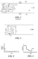
- Fig. 1 shows a prior art jam detection system where emitter e is located on one side of the conveyor at a potential jam site (sometimes determined a priori ) and a detector d opposite the emitter on the other side of the conveyor.
- a potential jam site sometimes determined a priori
- the detector will be blocked for some time causing the system to determine there is a jam when in fact there is none.
- a distance measuring sensor is used instead.
- the same set of adjacent parcels moving past the distance sensor will yield different distance measurements d 1 , d 2 , d 3 , d 4 , and the like as shown in Figs. 3 and 4 .
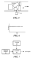
- Fig. 5 show distance detector 20 (e.g., a model DT-10 or DT-35 KED distance detector available from SICK Ag (sick.com)) mounted to emit electromagnetic radiation across conveyor belt 10.
- Fig. 5 shows a jam condition of the parcels on conveyor belt 10
- Fig. 6 shows how the distance to a parcel as measured by the distance detector does not change appreciably over a given period of time because the parcel is not moving very much in a jam condition.
- controller 24 is configured (e.g., programmed) to output a jam signal as shown in Figs. 8-9 .
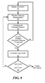
- Controller 24, Fig. 7 can include programming or logic which receives a distance measurement, step 30, Fig. 8 from the distance detector and compares that distance from a stored or logged previous distance as measure by the detector, step 32. If in step 34 the most recent distance measurement compared to the second most recent distance measurement is greater than a given threshold (e.g., 50 mm), this indicates a no jam condition (see d 2 compared to d 3 , Fig. 3 ) and the jam count is reset, step 36. Typically, the jam count is reset to zero.
- a given threshold e.g. 50 mm
- a jam condition signal is output. This signal may trigger an action such as an audible alarm or a "jam condition" indication on a screen or printout.
- the location of the jam condition may also be displayed based on the location of one or more distance measurement detectors.
- the jam count limit can be set at the factory or by the user to eliminate false positives and false negatives in a given parcel processing system. A typical setting might be 200.
- the controller may also provide a signal indicating that a jam condition does not exist whenever the jam count limit has not been reached.
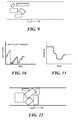
- Figs 9-11 show a non-jam condition on the conveyor belt which could have resulted in a false positive jam condition using a prior art optoelectric system (e.g., as shown in Fig. 1 ) but here, the jam count never exceeds the jam count threshold and thus false positive jam indications are reduced.
- Figs. 12-14 show a jam condition and how the jam count quickly exceeds the jam count threshold or limit in order to output a jam condition signal early in the jamming event so corrective action can be taken.
- Fig. 15 shows how controller 24, Fig. 7 , a system controller, system manager console, a programmable logic controller, or other similar means can use the jam signal in combination with information about the conveyor (see, for example encoder 22, Fig. 7 ) to process the jam signal, step 60 to provide a jam condition indication only when the jam signal is received and the conveyor is moving, step 62.
- Other information can be provided by controller 24 such as the jam location and the like. If encoder 22 is not provided, other means providing data can be used to determine whether or not the conveyor is currently moving.
- Multiple distance measuring detectors can be used in a facility each disposed at a known problematic or potential jam area at a set location with respect to parcels moving on the conveyor.
- a controller could be configured to process the signals output by multiple distance sensors.
- Fig. 16 shows a real non-jam condition
- Fig. 17 shows a real jam condition.
- the following jam detection algorithm script application parameters capture analog data from the distance sensor and convert the distance to millimeters. For every sample, the algorithm compares it with the previous value. In case the difference is less than a configurable threshold, the application will assume a potential jam and will increment a corresponding counter. In case the difference is greater than a threshold, the counter will be resent back to zero. If the counter becomes greater than a configurable maximum, a jam is detected.
- the application parameters are:
Landscapes
- Engineering & Computer Science (AREA)
- Physics & Mathematics (AREA)
- General Physics & Mathematics (AREA)
- Automation & Control Theory (AREA)
- General Engineering & Computer Science (AREA)
- Manufacturing & Machinery (AREA)
- Quality & Reliability (AREA)
- Control Of Conveyors (AREA)
Abstract
Description
- This application claims benefit of and priority to
U.S. Provisional Application Serial No. 61/992,279 filed May 13, 2014 - The subject invention relates to parcel processing conveyor systems.
- Modern parcel processing subsystems (e. g., FedEx, USPS, UPS, and the like) involve fairly large conveyors with high capacity and high throughput (e.g., four meters per second conveyor velocity).
- Jams can occur on the conveyor between the side rails thereof, at corners or along curves, and/or where there are gaps in the side rails.
- Prior photo-optic jam detection systems typically had an emitter on one side of the conveyor and a detector on the other side of the conveyor. With numerous adjacent articles on wide conveyors, false positive jam signals are the result.
-
- Featured in one preferred example is a new and more reliable conveyor jam detection system. When a jam condition occurs, any one parcel on the conveyor typically doesn't move very much and thus, if, at a set location, the distance from that location to the parcel is measured over time and the distance does not change appreciably, that information can more reliably be used to indicate a jam condition. Featured is a conveyor jam detection system adapted, in one example, to a parcel processing subsystem. A detector is located on one side of a conveyor. In a jam condition, the detector measures the distance to a now stationary parcel and outputs a constant distance measurement signal. In a non-jam condition, the detector measures the distance to a first moving parcel and then over time measures the distance to a second moving parcel which is at a different distance from the detector than the first moving parcel. The detector output then is a varying distance measurement signal over time. A controller (which may be a processor of the distance detector) receives the signals from the detector and is configured to determine if a jam condition exists based on the constant distance measurement signal and to determine if a non-jam condition exists based on the varying distance measurement signal. In one example, the controller is configured to determine if a jam condition exists by incrementing a jam count when a constant distance measurement signal is received from the detector and to output a jam condition signal if the jam count exceeds a set limit. The controller is preferably configured to determine if a non-jam condition exists by resetting the jam count when a varying distance measurement signal is received and then the jam condition signal is not output by the controller. The system controller may further be configured to determine if a jam condition exists by determining if the conveyor is moving and then outputting a jam condition signal only if the conveyor is moving and the jam count exceeds the set limit.
- Also featured is a conveyor jam detection method comprising measuring the distance to a stationary parcel and outputting a constant distance measurement signal, measuring the distance to a first moving parcel and measuring the distance to a second moving parcel at a different distance than a first moving parcel and, in response, outputting a varying distance measurement signal, determining if a jam condition exists based on the constant distance measurement signal, and determining if a non-jam condition exists based on the varying distance measurement signal. Determining if a jam condition exists may include incrementing a jam count when a constant distance measurement signal is received. A jam condition signal is output if the jam count exceeds a set limit. The jam count may be reset in response to a varying distance measurement signal.
- Also featured is a conveyor jam detection system including a distance detector located on one side of a conveyor oriented to detect the distance from the detector to parcels on the conveyor. A controller is responsive to the distance detector and is configured to compare distance measurements, to reset a jam count if different distance measurements are greater than a threshold, to increment the jam count if different distance measurements are less than the threshold, and output a jam condition signal if the jam count exceeds a set limit. The system may further include means for detecting whether the conveyor is moving. The controller is then preferably responsive to the means for detecting when the conveyor is moving and is further configured to output a jam condition signal only if the jam count exceeds the set limit and the conveyor is moving.
- A conveyor jam detection method includes measuring the distance of parcels on a conveyor from a set location, detecting whether the conveyor is moving, and detecting a jam condition based on whether the conveyor is moving and any changes of measured distances of a parcel over time.
- The subject invention, however, in other embodiments, need not achieve all these objectives and the claims hereof should not be limited to structures or methods capable of achieving these objectives.
- Other objects, features, and advantages will occur to those skilled in the art from the following description of a preferred embodiment and the accompanying drawings, in which:
- Fig. 1
- is a schematic top view of a prior art jam detection system;
- Fig. 2
- is a graph showing the output of the detector of the system of
Fig. 1 over time indicating a jam condition even though the parcels are not jammed resulting in a false positive situation; - Fig. 3
- is a schematic top view showing how a distance measurement device can be used to more reliably detect whether or not a jam condition is occurring ;
- Fig. 4
- is a graph showing the distance from a set location to various parcels on the conveyor shown in
Fig. 3 over time; - Fig. 5
- is a top schematic view showing parcels jammed on a conveyor;
- Fig. 6
- is a graph of the distance measured by the distance detector shown in
Fig. 5 over time; - Fig. 7
- is a block diagram showing the primary components associated with one preferred embodiment of the subject invention;
- Fig. 8
- is a flow chart depicting the primary steps associated with the programming or logic of the controller of
Fig. 7 and also depicting the primary steps associated with a method in accordance with the invention; - Fig. 9
- is a top view of a conveyor showing a non-jam condition;
- Fig. 10
- is a graph showing how the jam count never exceeds the jam count threshold when the method of
Fig. 8 is used; - Fig. 11
- is a graph showing distance measurements over time for the parcels on the conveyor of
Fig. 9 ; - Fig. 12
- is a schematic top view showing another jam condition;
- Fig. 13
- is a graph showing how the jam count increases over time in the jam situation shown in
Fig. 12 and exceeds the jam count threshold; - Fig. 14
- is a graph showing the output of the distance measurement sensor of
Fig. 12 ; - Fig. 15
- is a flow chart depicting the primary steps associated with downstream processing of a jam signal output by the system of the invention in order to determine whether a jam condition exists based on conveyor speed and the like;
- Fig. 16
- is a schematic three dimensional top view showing actual parcels on a high throughput, high capacity conveyor; and
- Fig. 17
- is a schematic three dimensional top view showing an actual jam condition on a high throughput, high volume parcel conveyor.
- Aside from the preferred embodiment or embodiments disclosed below, this invention is capable of other embodiments and of being practiced or being carried out in various ways. Thus, it is to be understood that the invention is not limited in its application to the details of construction and the arrangements of components set forth in the following description or illustrated in the drawings. If only one embodiment is described herein, the claims hereof are not to be limited to that embodiment. Moreover, the claims hereof are not to be read restrictively unless there is clear and convincing evidence manifesting a certain exclusion, restriction, or disclaimer.
-
Fig. 1 shows a prior art jam detection system where emitter e is located on one side of the conveyor at a potential jam site (sometimes determined a priori) and a detector d opposite the emitter on the other side of the conveyor. When numerous adjacent parcels as shown are moving on theconveyor belt 10 betweenside rails - In accordance with examples of the subject invention, a distance measuring sensor is used instead. Thus, the same set of adjacent parcels moving past the distance sensor will yield different distance measurements d1, d2, d3, d4, and the like as shown in
Figs. 3 and 4 . -
Fig. 5 show distance detector 20 (e.g., a model DT-10 or DT-35 KED distance detector available from SICK Ag (sick.com)) mounted to emit electromagnetic radiation acrossconveyor belt 10.Fig. 5 shows a jam condition of the parcels onconveyor belt 10 andFig. 6 shows how the distance to a parcel as measured by the distance detector does not change appreciably over a given period of time because the parcel is not moving very much in a jam condition. If the conveyor belt is moving as detected byoptional encoder 22,Fig. 7 or by some other means,controller 24 is configured (e.g., programmed) to output a jam signal as shown inFigs. 8-9 . -
Controller 24,Fig. 7 (e.g., a microcontroller, PIC controller, microprocessor, field programmable gate array, application specific integrated circuit, microcontroller integrated as a part of the distance sensor, or other logic means or combinations of the same) can include programming or logic which receives a distance measurement, step 30,Fig. 8 from the distance detector and compares that distance from a stored or logged previous distance as measure by the detector,step 32. If instep 34 the most recent distance measurement compared to the second most recent distance measurement is greater than a given threshold (e.g., 50 mm), this indicates a no jam condition (see d2 compared to d3,Fig. 3 ) and the jam count is reset,step 36. Typically, the jam count is reset to zero. If, however, the most recent distance measurement is less than the threshold, a potential jam condition exists and the jam count is incremented,step 38. When the jam count reaches the jam count limit,step 40, a jam condition signal is output. This signal may trigger an action such as an audible alarm or a "jam condition" indication on a screen or printout. The location of the jam condition may also be displayed based on the location of one or more distance measurement detectors. The jam count limit can be set at the factory or by the user to eliminate false positives and false negatives in a given parcel processing system. A typical setting might be 200. The controller may also provide a signal indicating that a jam condition does not exist whenever the jam count limit has not been reached. -
Figs 9-11 show a non-jam condition on the conveyor belt which could have resulted in a false positive jam condition using a prior art optoelectric system (e.g., as shown inFig. 1 ) but here, the jam count never exceeds the jam count threshold and thus false positive jam indications are reduced.Figs. 12-14 show a jam condition and how the jam count quickly exceeds the jam count threshold or limit in order to output a jam condition signal early in the jamming event so corrective action can be taken. -
Fig. 15 shows howcontroller 24,Fig. 7 , a system controller, system manager console, a programmable logic controller, or other similar means can use the jam signal in combination with information about the conveyor (see, forexample encoder 22,Fig. 7 ) to process the jam signal, step 60 to provide a jam condition indication only when the jam signal is received and the conveyor is moving,step 62. Other information can be provided bycontroller 24 such as the jam location and the like. Ifencoder 22 is not provided, other means providing data can be used to determine whether or not the conveyor is currently moving. - Multiple distance measuring detectors can be used in a facility each disposed at a known problematic or potential jam area at a set location with respect to parcels moving on the conveyor. A controller could be configured to process the signals output by multiple distance sensors.
- The preferred result is a more accurate, easy to install jam detection system.
Fig. 16 shows a real non-jam condition andFig. 17 shows a real jam condition. - The following jam detection algorithm script application parameters capture analog data from the distance sensor and convert the distance to millimeters. For every sample, the algorithm compares it with the previous value. In case the difference is less than a configurable threshold, the application will assume a potential jam and will increment a corresponding counter. In case the difference is greater than a threshold, the counter will be resent back to zero. If the counter becomes greater than a configurable maximum, a jam is detected. The application parameters are:
- recordResults = false -- Set to true if you want to save encoder and distance measurements for later playback.
- playBack = true -- Set to true to playback from the log file.
- logFilename = "recordJam3times.txt" -- File name for log results and playback
- debugLevel = true -- For Debugging
- hardwareTest = false -- Set to true to see the encoder ticks and the distance values on the screen
- conveyorFixedSpeed = true -- Enable/Disable fixed conveyor speed mode
- jamDetectLength = 5000 -- Total distance (in mm of conveyor travel) used to calculate a jam
- maxJamDistanceDiff = 50 -- Maximum difference between the samples (in mm) for jam detection
- Although specific features of the invention are shown in some drawings and not in others, this is for convenience only as each feature may be combined with any or all of the other features in accordance with the invention. The words "including", "comprising", "having", and "with" as used herein are to be interpreted broadly and comprehensively and are not limited to any physical interconnection. Moreover, any embodiments disclosed in the subject application are not to be taken as the only possible embodiments. Other embodiments will occur to those skilled in the art and are within the following claims.
- In addition, any amendment presented during the prosecution of the patent application for this patent is not a disclaimer of any claim element presented in the application as filed: those skilled in the art cannot reasonably be expected to draft a claim that would literally encompass all possible equivalents, many equivalents will be unforeseeable at the time of the amendment and are beyond a fair interpretation of what is to be surrendered (if anything), the rationale underlying the amendment may bear no more than a tangential relation to many equivalents, and/or there are many other reasons the applicant cannot be expected to describe certain insubstantial substitutes for any claim element amended.
Claims (12)
- A conveyor jam detection system comprising:a detector located on one side of a conveyor configured in a jam condition to measure the distance to a stationary parcel and to output a constant distance measurement signal and, in a non-jam condition, to measure the distance to a first moving parcel and then to measure the distance to a second moving parcel at a different distance from the detector than the first moving parcel and to output a varying distance measurement signal; anda controller receiving signals from the detector and configured to determine if a jam condition exists based on the constant distance measurement signal and to determine if a non-jam condition exists based on the varying distance measurement signal.
- The system of claim 1 in which the controller is configured to determine if a jam condition exists by incrementing a jam count when a constant distance measurement signal is received from the detector and to output a jam condition signal if the jam count exceeds a set limit.
- The system of any preceding claim in which the controller is configured to determine if a non-jam condition exists by resetting the jam count when a varying distance measurement signal is received.
- The system of any preceding claim in which a controller is configured to determine if a jam condition exists by further determining if the conveyor is moving and outputting a jam condition signal if the conveyor is moving and the jam count exceeds a set limit.
- A conveyor jam detection method comprising:measuring the distance to a stationary parcel and outputting a constant distance measurement signal;measuring the distance to a first moving parcel and measuring the distance to a second moving parcel at a different distance than a first moving parcel and, in response, outputting a varying distance measurement signal;determining if a jam condition exists based on the constant distance measurement signal; anddetermining if a non-jam condition exists based on the varying distance measurement signal.
- The method of claim 5 in which determining if a jam condition exists includes incrementing a jam count when a constant distance measurement signal is received and outputting a jam condition signal if the jam count exceeds a set limit.
- The method of claim 5 or 6 in which determining if a non-jam exists includes resetting the jam count in response to a varying distance measurement signal.
- The method of claim 5 or 6 in which determining if a jam condition exists includes determining if the conveyor is moving and outputting a jam condition signal only if the conveyor is moving and the jam count exceeds the set limit.
- A conveyor jam detection system comprising:a distance detector located on one side of a conveyor oriented to detect the distance from the detector to parcels on the conveyor;a controller responsive to the distance detector and configured:to compare distance measurements,to reset a jam count if different distance measurements are greater than a threshold,to increment the jam count if different distance measurements are less than the threshold, andoutput a jam condition signal if the jam count exceeds a set limit.
- The system of claim 9 further including means for detecting whether the conveyor is moving.
- The system of claim 9 or 10 in which the controller is responsive to the means for detecting when the conveyor is moving and is further configured to output a jam condition signal if the jam count exceeds the set limit and the conveyor is moving.
- A conveyor jam detection method comprising:measuring the distance of parcels on a conveyor from a set location;detecting whether the conveyor is moving; anddetecting a jam condition based on whether the conveyor is moving and any changes of measured distances of a parcel over time.
Applications Claiming Priority (1)
| Application Number | Priority Date | Filing Date | Title |
|---|---|---|---|
| US201461992279P | 2014-05-13 | 2014-05-13 |
Publications (2)
| Publication Number | Publication Date |
|---|---|
| EP2944591A1 true EP2944591A1 (en) | 2015-11-18 |
| EP2944591B1 EP2944591B1 (en) | 2017-07-12 |
Family
ID=53051719
Family Applications (1)
| Application Number | Title | Priority Date | Filing Date |
|---|---|---|---|
| EP15166291.3A Active EP2944591B1 (en) | 2014-05-13 | 2015-05-04 | Conveyor jam detection system and method |
Country Status (2)
| Country | Link |
|---|---|
| US (1) | US9477220B2 (en) |
| EP (1) | EP2944591B1 (en) |
Cited By (2)
| Publication number | Priority date | Publication date | Assignee | Title |
|---|---|---|---|---|
| WO2019222128A1 (en) * | 2018-05-16 | 2019-11-21 | Siemens Postal, Parcel & Airport Logistics Llc | Detection and removal of unstable parcel mail from an automated processing stream |
| EP4043111A1 (en) * | 2021-02-12 | 2022-08-17 | Siemens Aktiengesellschaft | Classifying items |
Families Citing this family (12)
| Publication number | Priority date | Publication date | Assignee | Title |
|---|---|---|---|---|
| EP3658600A4 (en) * | 2017-07-28 | 2021-06-02 | Phillips 66 Company | HIGH PERFORMANCE LARGE BANDWIDTH PROHIBITED POLYMERS, FOR ORGANIC PHOTOVOLTAICS |
| US10867380B1 (en) | 2019-07-01 | 2020-12-15 | Sas Institute Inc. | Object and data point tracking to control system in operation |
| US11176692B2 (en) | 2019-07-01 | 2021-11-16 | Sas Institute Inc. | Real-time concealed object tracking |
| US11521328B2 (en) * | 2019-10-16 | 2022-12-06 | Banner Engineering Corp | Image-based jam detection |
| US11744252B2 (en) | 2020-03-09 | 2023-09-05 | Lawrence Equipment Inc. | Self-clearing dough ball loader |
| US11985981B2 (en) | 2020-10-15 | 2024-05-21 | Lawrence Equipment, Inc. | Comestible flattener translation |
| JP7608174B2 (en) * | 2021-01-04 | 2025-01-06 | 株式会社東芝 | Information processing device and program |
| US12111397B2 (en) | 2021-03-09 | 2024-10-08 | Banner Engineering Corp. | Pixel domain field calibration of triangulation sensors |
| WO2022192876A1 (en) * | 2021-03-09 | 2022-09-15 | Banner Engineering Corp. | Non-contact motion detection sensor utilizing distance and intensity statistics |
| CN113197531A (en) * | 2021-03-30 | 2021-08-03 | 华帝股份有限公司 | Operation method of residue treatment module, residue treatment module and dish washing machine |
| CN116504038A (en) * | 2023-04-28 | 2023-07-28 | 华能安源发电有限责任公司 | Air volume early warning system and air volume early warning method of air volume measuring device |
| CN117058469B (en) * | 2023-10-11 | 2024-01-30 | 成都考拉悠然科技有限公司 | Tobacco bale blocking detection method based on deep learning |
Citations (5)
| Publication number | Priority date | Publication date | Assignee | Title |
|---|---|---|---|---|
| US3987429A (en) | 1975-11-11 | 1976-10-19 | Pitney-Bowes, Inc. | Malfunction detector system for item conveyor |
| US4258250A (en) | 1978-08-30 | 1981-03-24 | Copar Corporation | Jam detector |
| FR2690907A1 (en) * | 1992-05-06 | 1993-11-12 | Orangina France Sa | Blockage detecting appts. for conveyor - uses sensors distributed along conveyor, each sensor having tilting arm carrying magnet placed above reed switch. |
| WO2007084606A2 (en) * | 2006-01-20 | 2007-07-26 | L-3 Communications Security And Detection Systems, Inc. | Article positioner for a conveyor system |
| US8630537B2 (en) | 2008-07-08 | 2014-01-14 | United Parcel Service Of America, Inc. | Apparatus for monitoring a package handling system |
Family Cites Families (8)
| Publication number | Priority date | Publication date | Assignee | Title |
|---|---|---|---|---|
| US3150873A (en) * | 1962-03-29 | 1964-09-29 | Burroughs Corp | Item jam detection apparatus |
| US3558862A (en) * | 1969-04-15 | 1971-01-26 | Atomic Energy Commission | Circuit for dimensional verification of punched tapes |
| NL7103555A (en) * | 1971-03-17 | 1972-09-19 | ||
| US3779440A (en) * | 1972-04-20 | 1973-12-18 | Ibm | Form run-out and jam detector for printer |
| US4173276A (en) * | 1976-11-17 | 1979-11-06 | Standard-Knapp, Inc. | Apparatus for detecting and clearing a jam of articles |
| US5041850A (en) * | 1989-05-09 | 1991-08-20 | Nisshinbo Industries, Inc. | Controller of a label printer |
| US20060144899A1 (en) * | 2004-12-30 | 2006-07-06 | Hu Xiao P | Jam detection apparatus and method for indexing of substrates and lead frames |
| EP2965286A1 (en) * | 2013-03-04 | 2016-01-13 | Rite-Hite Holding Corporation | Methods and apparatus for video based process monitoring and control |
-
2015
- 2015-05-01 US US14/702,131 patent/US9477220B2/en active Active
- 2015-05-04 EP EP15166291.3A patent/EP2944591B1/en active Active
Patent Citations (5)
| Publication number | Priority date | Publication date | Assignee | Title |
|---|---|---|---|---|
| US3987429A (en) | 1975-11-11 | 1976-10-19 | Pitney-Bowes, Inc. | Malfunction detector system for item conveyor |
| US4258250A (en) | 1978-08-30 | 1981-03-24 | Copar Corporation | Jam detector |
| FR2690907A1 (en) * | 1992-05-06 | 1993-11-12 | Orangina France Sa | Blockage detecting appts. for conveyor - uses sensors distributed along conveyor, each sensor having tilting arm carrying magnet placed above reed switch. |
| WO2007084606A2 (en) * | 2006-01-20 | 2007-07-26 | L-3 Communications Security And Detection Systems, Inc. | Article positioner for a conveyor system |
| US8630537B2 (en) | 2008-07-08 | 2014-01-14 | United Parcel Service Of America, Inc. | Apparatus for monitoring a package handling system |
Cited By (4)
| Publication number | Priority date | Publication date | Assignee | Title |
|---|---|---|---|---|
| WO2019222128A1 (en) * | 2018-05-16 | 2019-11-21 | Siemens Postal, Parcel & Airport Logistics Llc | Detection and removal of unstable parcel mail from an automated processing stream |
| US11479418B2 (en) | 2018-05-16 | 2022-10-25 | Körber Supply Chain Llc | Detection and removal of unstable parcel mail from an automated processing stream |
| EP4043111A1 (en) * | 2021-02-12 | 2022-08-17 | Siemens Aktiengesellschaft | Classifying items |
| US12202012B2 (en) | 2021-02-12 | 2025-01-21 | Körber Supply Chain Logistics Gmbh | Classifying items |
Also Published As
| Publication number | Publication date |
|---|---|
| EP2944591B1 (en) | 2017-07-12 |
| US9477220B2 (en) | 2016-10-25 |
| US20150329296A1 (en) | 2015-11-19 |
Similar Documents
| Publication | Publication Date | Title |
|---|---|---|
| US9477220B2 (en) | Conveyor jam detection system and method | |
| CN109073748A (en) | Misalignment detection of vehicle radar sensors | |
| EP2146222A3 (en) | Microwave ranging sensor | |
| JP6721241B2 (en) | Goods sorting system | |
| JP5241461B2 (en) | Passenger detection device for passenger conveyor | |
| JP6606602B2 (en) | How to determine the speed of a rail vehicle | |
| EP0585301B1 (en) | Improvements in and relating to particle detection and analysis | |
| JP7312766B2 (en) | Input Count Rate Estimation for Radiation Pulse Detectors | |
| CN114206755B (en) | Test object, diagnostic system and article inspection device using the test object | |
| US20040200968A1 (en) | Apparatus and method for detecting alpha-ray | |
| JP4828962B2 (en) | Radioactivity inspection method and apparatus | |
| JP4469669B2 (en) | Method and apparatus for inspecting radioactive contamination | |
| JP7120608B2 (en) | Radiation measuring device | |
| US9507049B2 (en) | Object sensing using dynamic demodulation | |
| US8352214B2 (en) | Belt image zero tracking system | |
| JP6936466B2 (en) | Goods inspection system | |
| JP2015202458A (en) | Fruit and vegetable sorting device | |
| JP5255736B1 (en) | Radioactive contamination inspection device, inspection method and inspection program | |
| KR0157591B1 (en) | The counting system for fish | |
| JP5554189B2 (en) | Weighing conveyor device | |
| CN206177854U (en) | System for be used for scanning imagery | |
| RU74218U1 (en) | DEVICE FOR DETECTING RADIOACTIVE MATERIALS | |
| JP3577516B2 (en) | Radar equipment | |
| JP3076668B2 (en) | measuring device | |
| EA012257B1 (en) | Device for detection radioactive materials |
Legal Events
| Date | Code | Title | Description |
|---|---|---|---|
| PUAI | Public reference made under article 153(3) epc to a published international application that has entered the european phase |
Free format text: ORIGINAL CODE: 0009012 |
|
| 17P | Request for examination filed |
Effective date: 20150504 |
|
| AK | Designated contracting states |
Kind code of ref document: A1 Designated state(s): AL AT BE BG CH CY CZ DE DK EE ES FI FR GB GR HR HU IE IS IT LI LT LU LV MC MK MT NL NO PL PT RO RS SE SI SK SM TR |
|
| AX | Request for extension of the european patent |
Extension state: BA ME |
|
| RBV | Designated contracting states (corrected) |
Designated state(s): AL AT BE BG CH CY CZ DE DK EE ES FI FR GB GR HR HU IE IS IT LI LT LU LV MC MK MT NL NO PL PT RO RS SE SI SK SM TR |
|
| REG | Reference to a national code |
Ref country code: DE Ref legal event code: R079 Ref document number: 602015003480 Country of ref document: DE Free format text: PREVIOUS MAIN CLASS: B65H0007060000 Ipc: G05B0019418000 |
|
| GRAP | Despatch of communication of intention to grant a patent |
Free format text: ORIGINAL CODE: EPIDOSNIGR1 |
|
| RIC1 | Information provided on ipc code assigned before grant |
Ipc: B65G 43/08 20060101ALI20170202BHEP Ipc: G05B 19/042 20060101ALI20170202BHEP Ipc: G05B 19/418 20060101AFI20170202BHEP |
|
| GRAS | Grant fee paid |
Free format text: ORIGINAL CODE: EPIDOSNIGR3 |
|
| INTG | Intention to grant announced |
Effective date: 20170306 |
|
| GRAA | (expected) grant |
Free format text: ORIGINAL CODE: 0009210 |
|
| AK | Designated contracting states |
Kind code of ref document: B1 Designated state(s): AL AT BE BG CH CY CZ DE DK EE ES FI FR GB GR HR HU IE IS IT LI LT LU LV MC MK MT NL NO PL PT RO RS SE SI SK SM TR |
|
| REG | Reference to a national code |
Ref country code: GB Ref legal event code: FG4D |
|
| REG | Reference to a national code |
Ref country code: CH Ref legal event code: EP |
|
| REG | Reference to a national code |
Ref country code: AT Ref legal event code: REF Ref document number: 908919 Country of ref document: AT Kind code of ref document: T Effective date: 20170715 |
|
| REG | Reference to a national code |
Ref country code: IE Ref legal event code: FG4D |
|
| REG | Reference to a national code |
Ref country code: DE Ref legal event code: R096 Ref document number: 602015003480 Country of ref document: DE |
|
| REG | Reference to a national code |
Ref country code: NL Ref legal event code: MP Effective date: 20170712 |
|
| REG | Reference to a national code |
Ref country code: LT Ref legal event code: MG4D |
|
| PG25 | Lapsed in a contracting state [announced via postgrant information from national office to epo] |
Ref country code: NL Free format text: LAPSE BECAUSE OF FAILURE TO SUBMIT A TRANSLATION OF THE DESCRIPTION OR TO PAY THE FEE WITHIN THE PRESCRIBED TIME-LIMIT Effective date: 20170712 Ref country code: FI Free format text: LAPSE BECAUSE OF FAILURE TO SUBMIT A TRANSLATION OF THE DESCRIPTION OR TO PAY THE FEE WITHIN THE PRESCRIBED TIME-LIMIT Effective date: 20170712 Ref country code: SE Free format text: LAPSE BECAUSE OF FAILURE TO SUBMIT A TRANSLATION OF THE DESCRIPTION OR TO PAY THE FEE WITHIN THE PRESCRIBED TIME-LIMIT Effective date: 20170712 Ref country code: HR Free format text: LAPSE BECAUSE OF FAILURE TO SUBMIT A TRANSLATION OF THE DESCRIPTION OR TO PAY THE FEE WITHIN THE PRESCRIBED TIME-LIMIT Effective date: 20170712 Ref country code: NO Free format text: LAPSE BECAUSE OF FAILURE TO SUBMIT A TRANSLATION OF THE DESCRIPTION OR TO PAY THE FEE WITHIN THE PRESCRIBED TIME-LIMIT Effective date: 20171012 Ref country code: LT Free format text: LAPSE BECAUSE OF FAILURE TO SUBMIT A TRANSLATION OF THE DESCRIPTION OR TO PAY THE FEE WITHIN THE PRESCRIBED TIME-LIMIT Effective date: 20170712 |
|
| PG25 | Lapsed in a contracting state [announced via postgrant information from national office to epo] |
Ref country code: ES Free format text: LAPSE BECAUSE OF FAILURE TO SUBMIT A TRANSLATION OF THE DESCRIPTION OR TO PAY THE FEE WITHIN THE PRESCRIBED TIME-LIMIT Effective date: 20170712 Ref country code: IS Free format text: LAPSE BECAUSE OF FAILURE TO SUBMIT A TRANSLATION OF THE DESCRIPTION OR TO PAY THE FEE WITHIN THE PRESCRIBED TIME-LIMIT Effective date: 20171112 Ref country code: GR Free format text: LAPSE BECAUSE OF FAILURE TO SUBMIT A TRANSLATION OF THE DESCRIPTION OR TO PAY THE FEE WITHIN THE PRESCRIBED TIME-LIMIT Effective date: 20171013 Ref country code: LV Free format text: LAPSE BECAUSE OF FAILURE TO SUBMIT A TRANSLATION OF THE DESCRIPTION OR TO PAY THE FEE WITHIN THE PRESCRIBED TIME-LIMIT Effective date: 20170712 Ref country code: RS Free format text: LAPSE BECAUSE OF FAILURE TO SUBMIT A TRANSLATION OF THE DESCRIPTION OR TO PAY THE FEE WITHIN THE PRESCRIBED TIME-LIMIT Effective date: 20170712 Ref country code: PL Free format text: LAPSE BECAUSE OF FAILURE TO SUBMIT A TRANSLATION OF THE DESCRIPTION OR TO PAY THE FEE WITHIN THE PRESCRIBED TIME-LIMIT Effective date: 20170712 Ref country code: BG Free format text: LAPSE BECAUSE OF FAILURE TO SUBMIT A TRANSLATION OF THE DESCRIPTION OR TO PAY THE FEE WITHIN THE PRESCRIBED TIME-LIMIT Effective date: 20171012 |
|
| REG | Reference to a national code |
Ref country code: DE Ref legal event code: R097 Ref document number: 602015003480 Country of ref document: DE |
|
| PG25 | Lapsed in a contracting state [announced via postgrant information from national office to epo] |
Ref country code: RO Free format text: LAPSE BECAUSE OF FAILURE TO SUBMIT A TRANSLATION OF THE DESCRIPTION OR TO PAY THE FEE WITHIN THE PRESCRIBED TIME-LIMIT Effective date: 20170712 Ref country code: CZ Free format text: LAPSE BECAUSE OF FAILURE TO SUBMIT A TRANSLATION OF THE DESCRIPTION OR TO PAY THE FEE WITHIN THE PRESCRIBED TIME-LIMIT Effective date: 20170712 Ref country code: DK Free format text: LAPSE BECAUSE OF FAILURE TO SUBMIT A TRANSLATION OF THE DESCRIPTION OR TO PAY THE FEE WITHIN THE PRESCRIBED TIME-LIMIT Effective date: 20170712 |
|
| PLBE | No opposition filed within time limit |
Free format text: ORIGINAL CODE: 0009261 |
|
| STAA | Information on the status of an ep patent application or granted ep patent |
Free format text: STATUS: NO OPPOSITION FILED WITHIN TIME LIMIT |
|
| REG | Reference to a national code |
Ref country code: FR Ref legal event code: PLFP Year of fee payment: 4 |
|
| PG25 | Lapsed in a contracting state [announced via postgrant information from national office to epo] |
Ref country code: EE Free format text: LAPSE BECAUSE OF FAILURE TO SUBMIT A TRANSLATION OF THE DESCRIPTION OR TO PAY THE FEE WITHIN THE PRESCRIBED TIME-LIMIT Effective date: 20170712 Ref country code: SK Free format text: LAPSE BECAUSE OF FAILURE TO SUBMIT A TRANSLATION OF THE DESCRIPTION OR TO PAY THE FEE WITHIN THE PRESCRIBED TIME-LIMIT Effective date: 20170712 Ref country code: SM Free format text: LAPSE BECAUSE OF FAILURE TO SUBMIT A TRANSLATION OF THE DESCRIPTION OR TO PAY THE FEE WITHIN THE PRESCRIBED TIME-LIMIT Effective date: 20170712 |
|
| 26N | No opposition filed |
Effective date: 20180413 |
|
| PG25 | Lapsed in a contracting state [announced via postgrant information from national office to epo] |
Ref country code: SI Free format text: LAPSE BECAUSE OF FAILURE TO SUBMIT A TRANSLATION OF THE DESCRIPTION OR TO PAY THE FEE WITHIN THE PRESCRIBED TIME-LIMIT Effective date: 20170712 |
|
| REG | Reference to a national code |
Ref country code: BE Ref legal event code: MM Effective date: 20180531 |
|
| PG25 | Lapsed in a contracting state [announced via postgrant information from national office to epo] |
Ref country code: MC Free format text: LAPSE BECAUSE OF FAILURE TO SUBMIT A TRANSLATION OF THE DESCRIPTION OR TO PAY THE FEE WITHIN THE PRESCRIBED TIME-LIMIT Effective date: 20170712 |
|
| REG | Reference to a national code |
Ref country code: IE Ref legal event code: MM4A |
|
| PG25 | Lapsed in a contracting state [announced via postgrant information from national office to epo] |
Ref country code: LU Free format text: LAPSE BECAUSE OF NON-PAYMENT OF DUE FEES Effective date: 20180504 |
|
| PG25 | Lapsed in a contracting state [announced via postgrant information from national office to epo] |
Ref country code: IE Free format text: LAPSE BECAUSE OF NON-PAYMENT OF DUE FEES Effective date: 20180504 |
|
| PG25 | Lapsed in a contracting state [announced via postgrant information from national office to epo] |
Ref country code: BE Free format text: LAPSE BECAUSE OF NON-PAYMENT OF DUE FEES Effective date: 20180531 |
|
| PG25 | Lapsed in a contracting state [announced via postgrant information from national office to epo] |
Ref country code: MT Free format text: LAPSE BECAUSE OF NON-PAYMENT OF DUE FEES Effective date: 20180504 |
|
| REG | Reference to a national code |
Ref country code: AT Ref legal event code: UEP Ref document number: 908919 Country of ref document: AT Kind code of ref document: T Effective date: 20170712 |
|
| PG25 | Lapsed in a contracting state [announced via postgrant information from national office to epo] |
Ref country code: TR Free format text: LAPSE BECAUSE OF FAILURE TO SUBMIT A TRANSLATION OF THE DESCRIPTION OR TO PAY THE FEE WITHIN THE PRESCRIBED TIME-LIMIT Effective date: 20170712 |
|
| PG25 | Lapsed in a contracting state [announced via postgrant information from national office to epo] |
Ref country code: PT Free format text: LAPSE BECAUSE OF FAILURE TO SUBMIT A TRANSLATION OF THE DESCRIPTION OR TO PAY THE FEE WITHIN THE PRESCRIBED TIME-LIMIT Effective date: 20170712 |
|
| PG25 | Lapsed in a contracting state [announced via postgrant information from national office to epo] |
Ref country code: HU Free format text: LAPSE BECAUSE OF FAILURE TO SUBMIT A TRANSLATION OF THE DESCRIPTION OR TO PAY THE FEE WITHIN THE PRESCRIBED TIME-LIMIT; INVALID AB INITIO Effective date: 20150504 Ref country code: CY Free format text: LAPSE BECAUSE OF FAILURE TO SUBMIT A TRANSLATION OF THE DESCRIPTION OR TO PAY THE FEE WITHIN THE PRESCRIBED TIME-LIMIT Effective date: 20170712 Ref country code: MK Free format text: LAPSE BECAUSE OF NON-PAYMENT OF DUE FEES Effective date: 20170712 |
|
| PG25 | Lapsed in a contracting state [announced via postgrant information from national office to epo] |
Ref country code: AL Free format text: LAPSE BECAUSE OF FAILURE TO SUBMIT A TRANSLATION OF THE DESCRIPTION OR TO PAY THE FEE WITHIN THE PRESCRIBED TIME-LIMIT Effective date: 20170712 |
|
| PGFP | Annual fee paid to national office [announced via postgrant information from national office to epo] |
Ref country code: CH Payment date: 20240602 Year of fee payment: 10 |
|
| PGFP | Annual fee paid to national office [announced via postgrant information from national office to epo] |
Ref country code: AT Payment date: 20240517 Year of fee payment: 10 |
|
| PGFP | Annual fee paid to national office [announced via postgrant information from national office to epo] |
Ref country code: DE Payment date: 20250519 Year of fee payment: 11 |
|
| PGFP | Annual fee paid to national office [announced via postgrant information from national office to epo] |
Ref country code: IT Payment date: 20250530 Year of fee payment: 11 |
|
| PGFP | Annual fee paid to national office [announced via postgrant information from national office to epo] |
Ref country code: FR Payment date: 20250521 Year of fee payment: 11 |
|
| REG | Reference to a national code |
Ref country code: CH Ref legal event code: H13 Free format text: ST27 STATUS EVENT CODE: U-0-0-H10-H13 (AS PROVIDED BY THE NATIONAL OFFICE) Effective date: 20251223 |
|
| PG25 | Lapsed in a contracting state [announced via postgrant information from national office to epo] |
Ref country code: AT Free format text: LAPSE BECAUSE OF NON-PAYMENT OF DUE FEES Effective date: 20250504 |
|
| REG | Reference to a national code |
Ref country code: AT Ref legal event code: MM01 Ref document number: 908919 Country of ref document: AT Kind code of ref document: T Effective date: 20250504 |
|
| PG25 | Lapsed in a contracting state [announced via postgrant information from national office to epo] |
Ref country code: CH Free format text: LAPSE BECAUSE OF NON-PAYMENT OF DUE FEES Effective date: 20250531 |
|
| PGFP | Annual fee paid to national office [announced via postgrant information from national office to epo] |
Ref country code: GB Payment date: 20260324 Year of fee payment: 12 |