EP2944509B1 - Vehicle seat with moveable backrest - Google Patents
Vehicle seat with moveable backrest Download PDFInfo
- Publication number
- EP2944509B1 EP2944509B1 EP14405044.0A EP14405044A EP2944509B1 EP 2944509 B1 EP2944509 B1 EP 2944509B1 EP 14405044 A EP14405044 A EP 14405044A EP 2944509 B1 EP2944509 B1 EP 2944509B1
- Authority
- EP
- European Patent Office
- Prior art keywords
- backrest
- pneumatic cushion
- seat
- vehicle seat
- pump
- Prior art date
- Legal status (The legal status is an assumption and is not a legal conclusion. Google has not performed a legal analysis and makes no representation as to the accuracy of the status listed.)
- Active
Links
Images


Classifications
-
- B—PERFORMING OPERATIONS; TRANSPORTING
- B60—VEHICLES IN GENERAL
- B60N—SEATS SPECIALLY ADAPTED FOR VEHICLES; VEHICLE PASSENGER ACCOMMODATION NOT OTHERWISE PROVIDED FOR
- B60N2/00—Seats specially adapted for vehicles; Arrangement or mounting of seats in vehicles
- B60N2/90—Details or parts not otherwise provided for
- B60N2/914—Hydro-pneumatic adjustments of the shape
-
- B—PERFORMING OPERATIONS; TRANSPORTING
- B64—AIRCRAFT; AVIATION; COSMONAUTICS
- B64D—EQUIPMENT FOR FITTING IN OR TO AIRCRAFT; FLIGHT SUITS; PARACHUTES; ARRANGEMENTS OR MOUNTING OF POWER PLANTS OR PROPULSION TRANSMISSIONS IN AIRCRAFT
- B64D11/00—Passenger or crew accommodation; Flight-deck installations not otherwise provided for
- B64D11/06—Arrangements of seats, or adaptations or details specially adapted for aircraft seats
- B64D11/0649—Seats characterised by special features for reducing weight
-
- B—PERFORMING OPERATIONS; TRANSPORTING
- B60—VEHICLES IN GENERAL
- B60N—SEATS SPECIALLY ADAPTED FOR VEHICLES; VEHICLE PASSENGER ACCOMMODATION NOT OTHERWISE PROVIDED FOR
- B60N2/00—Seats specially adapted for vehicles; Arrangement or mounting of seats in vehicles
- B60N2/24—Seats specially adapted for vehicles; Arrangement or mounting of seats in vehicles for particular purposes or particular vehicles
- B60N2/32—Seats specially adapted for vehicles; Arrangement or mounting of seats in vehicles for particular purposes or particular vehicles convertible for other use
- B60N2/34—Seats specially adapted for vehicles; Arrangement or mounting of seats in vehicles for particular purposes or particular vehicles convertible for other use into a bed
-
- B—PERFORMING OPERATIONS; TRANSPORTING
- B60—VEHICLES IN GENERAL
- B60N—SEATS SPECIALLY ADAPTED FOR VEHICLES; VEHICLE PASSENGER ACCOMMODATION NOT OTHERWISE PROVIDED FOR
- B60N2/00—Seats specially adapted for vehicles; Arrangement or mounting of seats in vehicles
- B60N2/24—Seats specially adapted for vehicles; Arrangement or mounting of seats in vehicles for particular purposes or particular vehicles
- B60N2/32—Seats specially adapted for vehicles; Arrangement or mounting of seats in vehicles for particular purposes or particular vehicles convertible for other use
- B60N2/36—Seats specially adapted for vehicles; Arrangement or mounting of seats in vehicles for particular purposes or particular vehicles convertible for other use into a loading platform
-
- B—PERFORMING OPERATIONS; TRANSPORTING
- B64—AIRCRAFT; AVIATION; COSMONAUTICS
- B64D—EQUIPMENT FOR FITTING IN OR TO AIRCRAFT; FLIGHT SUITS; PARACHUTES; ARRANGEMENTS OR MOUNTING OF POWER PLANTS OR PROPULSION TRANSMISSIONS IN AIRCRAFT
- B64D11/00—Passenger or crew accommodation; Flight-deck installations not otherwise provided for
- B64D11/06—Arrangements of seats, or adaptations or details specially adapted for aircraft seats
- B64D11/0639—Arrangements of seats, or adaptations or details specially adapted for aircraft seats with features for adjustment or converting of seats
- B64D11/0641—Seats convertible into beds
-
- B—PERFORMING OPERATIONS; TRANSPORTING
- B64—AIRCRAFT; AVIATION; COSMONAUTICS
- B64D—EQUIPMENT FOR FITTING IN OR TO AIRCRAFT; FLIGHT SUITS; PARACHUTES; ARRANGEMENTS OR MOUNTING OF POWER PLANTS OR PROPULSION TRANSMISSIONS IN AIRCRAFT
- B64D11/00—Passenger or crew accommodation; Flight-deck installations not otherwise provided for
- B64D11/06—Arrangements of seats, or adaptations or details specially adapted for aircraft seats
- B64D11/0647—Seats characterised by special upholstery or cushioning features
-
- Y—GENERAL TAGGING OF NEW TECHNOLOGICAL DEVELOPMENTS; GENERAL TAGGING OF CROSS-SECTIONAL TECHNOLOGIES SPANNING OVER SEVERAL SECTIONS OF THE IPC; TECHNICAL SUBJECTS COVERED BY FORMER USPC CROSS-REFERENCE ART COLLECTIONS [XRACs] AND DIGESTS
- Y02—TECHNOLOGIES OR APPLICATIONS FOR MITIGATION OR ADAPTATION AGAINST CLIMATE CHANGE
- Y02T—CLIMATE CHANGE MITIGATION TECHNOLOGIES RELATED TO TRANSPORTATION
- Y02T50/00—Aeronautics or air transport
- Y02T50/40—Weight reduction
Definitions
- the invention relates to a vehicle seat with at least one back, which is movable in a substantially horizontal position and which has at least one pneumatic cushion and a corresponding method.
- Vehicle seats which can be transformed by a movement of a back, such as a backrest to a substantially horizontal lying surface, are known in particular in aircraft.
- a fundamental problem of such vehicle seats is the increased space requirement in the longitudinal direction in the lying configuration, in particular with regard to possible collisions with other vehicle seats or elements of the vehicle.
- such seats are at least partially shielded from the rest of the cabin by a frame or divider wall to provide the greatest possible privacy to a passenger.
- a frame or divider wall to provide the greatest possible privacy to a passenger.
- a frame or divider wall to provide the greatest possible privacy to a passenger.
- Especially in the presence of such frames or partitions of the increased space requirement of the aircraft seat in a reclining configuration is problematic, since the space occupied by a seat by the frame or the partition is additionally limited.
- the EP 0 869 060 discloses aircraft seats housed in a frame. During the transition from a sitting to a lying position, the seat is moved forward relative to the frame, and the seat surface and the backrest are pivoted relative to the frame. Individual parts of the seat, such as the headrest, may include pneumatic elements to allow adjustment of the seat to the needs of the user.
- the EP 2 234 884 B1 (British Airways) describes an aircraft passenger seat that converts to a substantially flat bed.
- the seat includes a seat, a backrest and a shell that partially surrounds the seat.
- a headrest of the backrest is movable and has a pneumatic element, with which the headrest can be pivoted, in particular to optimally support the head of a passenger.
- the air in the pneumatic element can be automatically drained, so that the headrest occupies a horizontal position.
- the EP 1 781 539 B1 (Premium Aircraft Interiors) discloses an aircraft seat that transforms into a bed.
- the aircraft seat is arranged at an angle to the cabin wall, so that a resulting triangular space between the head of the seat and cabin wall can be used in the reclined position of the seat.
- the length of the combination backrest and headrest is temporarily shortened during lowering.
- Drive means, a relative displacement between the backrest and headrest, so that they are moved back to each other when lowering and after lowering done away from each other.
- the US4669780 shows a vehicle seat according to the preamble of claim 1.
- the object of the invention is to provide a vehicle seat belonging to the aforementioned technical field, which allows the simplest possible transition from a sitting position to a lying position and has the simplest possible construction and the lowest possible weight.
- the vehicle seat comprises a seat surface and at least one backrest which is at an angle to the seat surface.
- the angle between the seat surface and the at least one backrest can be adjusted via an adjusting device between a first position, in which the at least one back essentially at right angles to the seat and a second position, in which the seat and the at least one backrest in the Form essentially flat surface, change.
- the at least one back rest is against the seat at its first end.
- a second end of the back comprises at least one pneumatic pad which is fluidly connected to a pump.
- the pump is controlled via a control device that is configured such that as the backrest moves from the first position to the second position, the pneumatic cushion is substantially completely deflated or inflated by the pump.
- the length of the at least one backrest can be changed dynamically and adapted to the respective position of the at least one backrest relative to the seat surface. Since no mechanical system is necessary for this purpose, the vehicle seat can be constructed relatively simply and weight can be saved, which has significant advantages in particular when used as an aircraft seat.
- the length of the at least one backrest by inflating and deflating the at least one pneumatic cushion, a collision of the second end of the at least one backrest with another vehicle seat or another cabin element can be prevented when the at least one backrest is moved.
- vehicle means all means of transport with which persons can be transported on land, in the air or on the water. These are in particular automobiles, buses, trains, planes, helicopters, boats and ships. Accordingly, the term “vehicle seat” is understood to mean a seat for use in one of these vehicles.
- the adjusting device is preferably equipped with an electric motor, so that the angle between the seat and the at least one back can be adjusted by a user of the vehicle seat via a corresponding control device.
- the adjustment may also consist of a mechanism that allows the adjustment of the at least one back by pressing or pulling the user and the locking of the back at a certain angle between the seat and backrest.
- the first position corresponds to a normal seating position.
- the at least one backrest is essentially at a right angle to the seat surface. "Substantially" in the present application means a deviation of at most 10 °, but preferably at most less than 5 ° to the right angle.
- both the seat surface and the at least one backrest comprise a cushion which is adjustable in its hardness and which is configured in particular as at least one further pneumatic cushion.
- the angle between the backrest and the seat is about 180 °, i. the seat surface and the at least one backrest form a substantially flat surface, which is suitable in particular for lying.
- the adjusting device is preferably designed such that a locking of the at least one backrest at any angle between the first and second position is possible, so that a user of the vehicle seat receives the greatest possible flexibility in setting a comfortable sitting position.
- the second end of the backrest includes at least one pneumatic cushion.
- a "pneumatic cushion” is understood to mean a chamber enclosed by a sheet material which can be inflated with a fluid, in particular with air. Accordingly, the volume of a pneumatic cushion can be varied by varying the amount of fluid charged. Particularly preferably, the at least one pneumatic cushion in the vehicle seat according to the invention can be changed in its volume by active inflation and deflation.
- the second end of the back consists exclusively of the at least one pneumatic cushion.
- the at least one pneumatic cushion is particularly preferably arranged in the extension direction of the backrest. If the at least one pneumatic cushion is completely inflated, the at least one backrest accordingly has a greater length than if the at least one pneumatic cushion is completely emptied. Accordingly, by inflating and emptying the at least one pneumatic cushion, the total length of the at least one backrest can be increased or decreased.
- the inflation and deflation of the at least one pneumatic cushion is preferably carried out by a pump, which is fluidically connected to the pneumatic cushion.
- the pump can pump in at least one supply line, a fluid either in the at least one pneumatic cushion or emptying this by suction
- the at least one supply line preferably has at least one valve with which the fluidic connection between the pump and the at least one pneumatic cushion can be interrupted or released.
- several pneumatic cushions can be inflated or emptied using the same pump.
- a plurality of such valves are combined in a valve block. This has the advantage that all valves for one or more vehicle seats are collected centrally in one place, the connection between each valve and the corresponding pneumatic cushion being made via a specific supply line.
- each pump block can be assigned a pump. This simplifies the construction of the vehicle seat and also enables a simplified maintenance and a simple replacement of the valves.
- the vehicle seat can also have connection valves, with which the at least one pneumatic cushion can be connected to a compressed air and / or vacuum system of the vehicle, in which case the inflation and deflation of the at least one pneumatic cushion is controlled via corresponding valves.
- the vehicle seat comprises further pneumatic cushions on the seat surface and / or the at least one backrest, wherein these can be at least partially inflated and deflated by the control device to allow an individual adjustment of the hardness of these surfaces or of portions of these surfaces by the user ,
- the control device is preferably an electronic control comprising a microchip and a memory module.
- the control device is preferably equipped with at least one sensor or connected via an interface with the adjusting device in order to be able to determine the angle between the at least one backrest and the seat surface.
- the at least one pneumatic cushion can be emptied or inflated.
- substantially completely emptied in the context of the present application means that the volume of the pneumatic cushion is reduced by removing the fluid to less than 2%, more preferably to less than 1% of the fully inflated volume.
- the at least one backrest is designed as a backrest, wherein the control device is configured such that the at least one pneumatic cushion is substantially completely emptied when the backrest is moved from the first position to the second position.
- control device is configured such that the at least one pneumatic cushion is completely deflated in the second position of the backrest.
- the base area necessary for the vehicle seat can be reduced in the second position relative to a vehicle seat, in which no change in length of the backrest takes place.
- control device is configured such that the at least one pneumatic cushion is first completely emptied after reaching a first predetermined angle between the seat surface and the backrest and is inflated again when a second, predetermined angle is reached at least one pneumatic cushion is at least partially inflated upon reaching the second position by the backrest.
- the at least one pneumatic cushion when adjusting the seat back, there may be an area where the seat back would collide with the cabin wall.
- the at least one pneumatic cushion By emptying the at least one pneumatic cushion, the length of the backrest can be reduced so far that a collision-free passage of the second end of the backrest to the cabin wall is possible.
- the at least one pneumatic cushion again at least partially, but preferably fully inflated so that a user of the aircraft seat is the largest possible lying area available.
- the vehicle seat preferably has a frame which, in the second position, at least partially encloses the second end of the backrest.
- the frame encloses at least a portion of the vehicle seat to permit at least partial separation of the seating area from the interior of the vehicle.
- the frame particularly preferably extends behind the backrest and partially laterally relative to the seat. As a result, a kind of "single cabin feeling" can be created for a user.
- shelves or other functional elements such as extending tables or entertainment systems can be integrated on and within the frame.
- the frame is designed such that the second end of the backrest is completely enclosed in the second position of this. This shields a user during sleep from the noise of the vehicle or passengers and thus increases its comfort.
- the second end of the backrest with the at least one pneumatic cushion is preferably not enclosed by the frame.
- the frame is arranged immovable relative to the seat at least in the horizontal direction. Since the total length of the backrest can be reduced by emptying the at least one pneumatic cushion, a relative movement between the seat surface and the frame is not necessary to prevent a collision of the backrest with the frame when adjusting the backrest in the second position.
- the seat is immovable relative to the frame only relative to movement in the horizontal direction, while vertical movement remains possible relative to the frame.
- the distance of the seat to the vehicle floor can be changed, which allows an optimal adjustment of the seat height to the size of a user, in particular at the leg length.
- the angle of at least part of the seat surface to the vehicle floor can be changed. As a result, the vehicle seat can be optimally adjusted by a user to his needs.
- the back is formed as a leg rest
- the control device is configured such that the at least one pneumatic cushion is substantially completely inflated when moving the leg rest from the first position to the second position by the pump.
- the control device is further configured such that in the second position, the at least one pneumatic cushion of the leg rest is completely inflated.
- the legrest in the first position, is dimensioned such that it extends to the vehicle floor or leaves a gap therewith, in order to be able to stow a smaller piece of luggage under the seat.
- the length of the leg rest is then too short to fully support the user's legs.
- so-called "ottomans" are provided, on which a user of the seat can hang up the feet.
- control device is configured such that the at least one pneumatic cushion is inflated or deflated depending on the angle between the seat surface and the at least one backrest.
- the emptying or inflation of the at least one pneumatic cushion is carried out by the pump preferably upon reaching a certain angle between the at least one back and the seat.
- the control device is coupled to the adjusting device.
- a sensor connected to the control device can monitor the angle between the seat surface and the at least one backrest.
- the at least one pneumatic cushion is continuously emptied during the adjustment of the at least one backrest from the first position in the direction of the second position or continuously inflated when adjusting from the second position in the direction of the first position or vice versa.
- the vehicle seat preferably comprises a pressure sensor which continuously measures the pressure of a fluid located in the at least one pneumatic cushion.
- the control device is further configured such that when a predetermined maximum pressure is exceeded by the pump, fluid is discharged from the at least one pneumatic pad until the predetermined maximum pressure is reached.
- the at least one pneumatic cushion automatically deflates so much that it can move past the obstacle without being damaged.
- an obstacle such as a wall of the vehicle cabin
- it could be squeezed between the at least one backrest and the obstacle, thereby increasing the pressure of the fluid inside the at least one pneumatic cushion would. This increase in pressure could damage the at least one pneumatic pad, such as cracking.
- continuous pressure measurement is understood as meaning any measurement in which the pressure is measured only occasionally, but at regular and short intervals, for example every few microseconds up to a maximum of every 5 seconds.
- the pressure sensor is arranged in or on a feed line between the pump and the at least one pneumatic cushion. If a valve block is used, then a pressure sensor can be arranged on the side of the supply line on each valve. This allows a simple construction of the vehicle seat.
- Such a continuous pressure measurement with subsequent readjustment of the pressure when exceeding the predetermined maximum pressure can not only be used within the scope of the present invention, but can also be used in other applications in which a pneumatic cushion is used.
- a control for example, on pneumatic cushions, which are used as a seat, backrest, room divider, pad, lying surface or the like, can be used.
- this pneumatic cushions can be equipped in a variety of applications.
- the predetermined maximum pressure inside the at least one pneumatic cushion of the vehicle seat according to the invention is preferably 5 kPa (50 mbar). Depending on the intended use of the pneumatic cushion, however, other maximum pressures may also be provided, such as 10 kPa (100 mbar) or 1 kPa (10 mbar).
- the vehicle seat according to the invention is an aircraft seat. Due to the space and weight-saving design and the increased comfort for the user, a erfindungsgmässer vehicle seat is ideal for use in aircraft, especially in cabins in the higher booking classes.
- the present application further relates to a method for moving at least one backrest of a vehicle seat from a first position, in which the at least one backrest is substantially at right angles to a seat surface, into a second position, in which the at least one backrest engages with the seat surface forms substantially flat surface.
- a second end of the at least one backrest includes at least one pneumatic pad that is completely deflated or inflated by a pump during movement from the first position to the second position.
- the inflation and deflation by the pump is preferably carried out completely automatically, for example by a control device, which causes depending on the angle between the at least one back and the seat inflation or emptying of the at least one pneumatic cushion by the pump.
- the control device may be coupled to the adjusting device.
- a sensor connected to the control device can also detect a movement of the at least one backrest from the first to the second position or vice versa.
- a backrest is moved, wherein the at least one pneumatic cushion is completely emptied during movement from the first position to the second position.
- the length of the backrest can be reduced in a movement from the second position to the first position by the complete emptying of the at least one pneumatic cushion, whereby a possible collision of the second end of the backrest with another vehicle seat or a other element of the vehicle cab can be prevented.
- This is particularly advantageous in aircraft seats, as a total of more seats can be arranged one behind the other without the collision with another vehicle seat or an element of the cabin threatens when adjusting the backrest in the second position.
- the at least one pneumatic cushion upon reaching a first predetermined angle between the backrest and the seat by the pump completely emptied and then filled again when reaching a second predetermined angle, so that the at least one pneumatic cushion is at least partially filled when reaching the second position by the backrest.
- the at least one pneumatic pad is refilled, e.g. To provide a user of the vehicle seat a maximum bed surface.
- the two angles are determined on the basis of the actual spatial conditions in the interior of the cabin of the vehicle, these being particularly preferably stored in the control device.
- the first predetermined angle is 40 ° and the second predetermined angle is 75 °.
- the at least one pneumatic cushion is completely deflated in the second position of the backrest. This allows a reduction in the required for the vehicle seat base in the second position, which can be arranged in the vehicle cabin more seats one behind the other.
- a leg rest is moved, wherein the at least one pneumatic cushion is completely inflated when moving the leg rest from the first position to the second position.
- the leg rest in the second position, which corresponds to a reclining or relaxed position, can have a sufficiently long length in order to optimally support the legs of a user of the vehicle seat.
- the pressure of a fluid filled in at least one pneumatic pad is continuously measured by means of a pressure sensor, wherein when a predetermined Maimal horres is exceeded via the pump fluid from the at least one pneumatic pad is emptied until the pressure corresponds to the maximum pressure.
- This method step does not necessarily have to be used only in combination with the method according to the invention for moving at least one backrest, but can also be used independently of pneumatic cushions of any kind.
- the Fig. 1 shows an embodiment of an inventive vehicle seat 1 with an adjustable backrest 3.1 in a first position.
- a backrest 3.1 substantially at right angles to a seat 2 of the vehicle seat 1.
- the angle between the seat 2 and the backrest 3.1 change, ie the backrest 3.1 can be moved relative to the seat surface 2
- the adjusting device 6 comprises an electric motor with which the angle between the seat 2 and the backrest 3.1 can be adjusted.
- the backrest 3.1 abuts against the seat surface 2 at a first end 11.
- the second end 10.1 of the backrest 3.1 comprises a pneumatic cushion 4, which serves as a headrest.
- the pneumatic cushion 4 is connected via feed lines (not shown) to a pump 7, wherein the pneumatic cushion 4 can be inflated and emptied via the pump 7.
- the pneumatic cushion 4 In the first position, the pneumatic cushion 4 is completely inflated, ie the backrest 3.1 has a maximum length in this position.
- the pump 7 is thereby controlled by a control device (not shown), ie the control device gives the pump 7 and any existing valves corresponding control commands to inflate or deflate the pneumatic cushion.
- the vehicle seat is connected to a floor of the vehicle via a corresponding substructure 8, which in the embodiment shown is configured by way of example as legs. Furthermore, the vehicle seat 1 is partially enclosed by a frame 5. In the first position, the second end 10. 1 of the backrest and thus the pneumatic cushion 4 are not enclosed by the frame 5. If the backrest 3.1 is moved to the second position, the frame 5 encloses this second end 10.1 with the pneumatic cushion 4 at least partially.
- the frame 5 has a support 9 which supports the backrest 3.1 in the second position (as in FIG Fig. 2 shown).
- the Fig. 2 shows the vehicle seat 1 from the Fig. 1 in the second position.
- the seat 2 and the backrest 3.1 form a substantially flat surface, ie the angle between the seat 2 and the backrest 3.1 is approximately 180 °.
- the pneumatic cushion 4 is completely empty, ie the backrest 3.1 has a minimum length.
- the frame 5 would have to be made longer in the horizontal direction, which would increase the necessary base area for the vehicle seat 1.
- Figs. 3a-3c show a second embodiment of an inventive vehicle seat 1 with an adjustable backrest 3.1.
- the pneumatic cushion 4 is completely emptied when reaching a first predetermined angle 12.1 between the backrest 3.1 and the seat 2.
- the Fig. 3a shows the vehicle seat 1 when reaching the first angle 12.1. Between the first position of the backrest 3.1 and the reaching of the first angle 12.1, the pneumatic cushion 4 is completely inflated. After the backrest has passed the first predetermined angle 12.1, the pneumatic cushion 4 is completely emptied.
- the pneumatic pad 4 In the area between the first predetermined angle 12.1 and a second predetermined angle 12.2, the pneumatic pad 4 remains completely empty, as shown in FIG Fig. 3b is shown. Only when reaching the second predetermined angle 12.2, the pneumatic cushion 4 is inflated again.
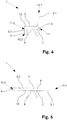
- the Fig. 4 shows a further embodiment of an inventive vehicle seat 1 with a movable legrest 3.2.
- the leg rest 3.2 is connected via a second adjustment mechanism 13 from a first position, in which the leg rest 3.2 is substantially at right angles to the seat surface 2, into a second position, in which the leg rest 3.2 and the seat surface 2 essentially form a flat surface ( see Fig. 6), movable.
- the leg rest 3.2 rests with a first end 11.2 on the seat surface 2.
- a second end 10.2 of the legrest 3.2 comprises a pneumatic cushion 4, which can be inflated or deflated by means of a pump 7.
- the vehicle seat 1 comprises a backrest 3.1, which is movable relative to the seat surface 2 via a first adjusting mechanism 6.
- the backrest does not have a pneumatic cushion.
- a further pneumatic cushion may be arranged, as in the embodiments of Figs. 1 and 3 is shown.
- the Fig. 5 shows the vehicle seat 1 of Fig. 4 in the second position, wherein both the legrest 3.2 and the backrest 3.1 have both been moved relative to the seat surface 2 to form a substantially flat surface.
- the pneumatic pad 4 was completely inflated by the pump 7.
- the control of the pump 7 and any valves also takes place in this embodiment via a control device (not shown).
Description
Die Erfindung betrifft einen Fahrzeugsitz mit wenigstens einer Lehne, welche in eine im Wesentlichen waagrechte Position bewegbar ist und welche mindestens ein pneumatisches Kissen aufweist und ein entsprechendes Verfahren.The invention relates to a vehicle seat with at least one back, which is movable in a substantially horizontal position and which has at least one pneumatic cushion and a corresponding method.
Fahrzeugsitze, welche sich durch eine Bewegung einer Lehne, wie beispielsweise einer Rückenlehne zu einer im Wesentlichen waagrechten Liegefläche verwandeln lassen, sind insbesondere im Flugzeugbau bekannt. Ein grundlegendes Problem derartiger Fahrzeugsitze ist der gesteigerte Platzbedarf in Längsrichtung in der Liegekonfiguration, insbesondere in Bezug auf mögliche Kollisionen mit weiteren Fahrzeugsitzen oder Elementen des Fahrzeugs. Oft sind in den teureren Beförderungsklassen derartige Sitze zumindest teilweise durch einen Rahmen oder eine Trennwand vom Rest der Kabine abgeschirmt, um einem Passagier die grösstmögliche Privatsphäre zu gewähren. Gerade bei Anwesenheit solcher Rahmen oder Trennwände ist der gesteigerte Platzbedarf des Flugzeugsitzes in einer Liegekonfiguration problematisch, da der von einem Sitz eingenommene Platz durch den Rahmen oder der Trennwand zusätzlich begrenzt wird.Vehicle seats, which can be transformed by a movement of a back, such as a backrest to a substantially horizontal lying surface, are known in particular in aircraft. A fundamental problem of such vehicle seats is the increased space requirement in the longitudinal direction in the lying configuration, in particular with regard to possible collisions with other vehicle seats or elements of the vehicle. Often, in the more expensive classes of transport, such seats are at least partially shielded from the rest of the cabin by a frame or divider wall to provide the greatest possible privacy to a passenger. Especially in the presence of such frames or partitions of the increased space requirement of the aircraft seat in a reclining configuration is problematic, since the space occupied by a seat by the frame or the partition is additionally limited.
Die
Die
Die
Aufgabe der Erfindung ist es, einen dem eingangs genannten technischen Gebiet zugehörenden Fahrzeugsitz zu schaffen, der einen möglichst einfachen Übergang von einer Sitz- in eine Liegeposition ermöglicht und eine möglichst einfache Konstruktion sowie ein möglichst geringes Gewicht aufweist.The object of the invention is to provide a vehicle seat belonging to the aforementioned technical field, which allows the simplest possible transition from a sitting position to a lying position and has the simplest possible construction and the lowest possible weight.
Die Lösung der Aufgabe ist durch die Merkmale des Anspruchs 1 definiert. Gemäss der Erfindung umfasst der Fahrzeugsitz eine Sitzfläche sowie wenigstens eine zur Sitzfläche in einem Winkel stehende Lehne. Der Winkel zwischen der Sitzfläche und der wenigstens einen Lehne lässt sich über eine Verstellvorrichtung zwischen einer ersten Position, in der die wenigstens eine Lehne im Wesentlichen im rechten Winkel zur Sitzfläche steht und einer zweiten Position, in der die Sitzfläche und die wenigstens eine Lehne eine im Wesentlichen ebene Fläche bilden, verändern. Die wenigstens eine Lehne liegt an ihrem ersten Ende an der Sitzfläche an. Ein zweites Ende der Lehne umfasst mindestens ein pneumatisches Kissen, welches mit einer Pumpe fluidisch verbunden ist. Die Pumpe wird über eine Steuerungsvorrichtung gesteuert, welche derart konfiguriert ist, dass beim Bewegen der Rückenlehne von der ersten Position in die zweite Position das pneumatische Kissen durch die Pumpe im Wesentlichen vollständig entleert oder aufgeblasen wird.The solution of the problem is defined by the features of
Durch das Vorsehen von mindestens einem pneumatischen Kissen lässt sich die Länge der wenigstens einen Lehne dynamisch verändern und an die jeweilige Position der wenigstens einen Lehne relativ zur Sitzfläche anpassen. Da hierfür keine Mechanik nötig ist, kann der Fahrzeugsitz relativ einfach aufgebaut und Gewicht eingespart werden, was insbesondere beim Einsatz als Flugzeugsitz wesentliche Vorteile aufweist. Zudem lässt sich durch das dynamische Anpassen der Länge der wenigstens einen Lehne durch das Aufblasen und Entleeren des mindestens einen pneumatischen Kissens beim Bewegen der wenigstens einen Lehne eine Kollision des zweiten Endes der wenigstens einen Lehne mit einem weiteren Fahrzeugsitz oder einem weiteren Kabinenelement verhindern.By providing at least one pneumatic cushion, the length of the at least one backrest can be changed dynamically and adapted to the respective position of the at least one backrest relative to the seat surface. Since no mechanical system is necessary for this purpose, the vehicle seat can be constructed relatively simply and weight can be saved, which has significant advantages in particular when used as an aircraft seat. In addition, by dynamically adjusting the length of the at least one backrest by inflating and deflating the at least one pneumatic cushion, a collision of the second end of the at least one backrest with another vehicle seat or another cabin element can be prevented when the at least one backrest is moved.
Als "Fahrzeug" im Sinne der vorliegenden Anmeldung werden sämtliche Beförderungsmittel verstanden, mit denen sich Personen zu Lande, in der Luft oder auf dem Wasser transportieren lassen. Dies sind insbesondere Automobile, Busse, Züge, Flugzeuge, Helikopter, Boote und Schiffe. Dementsprechend wird unter dem Begriff "Fahrzeugsitz" ein Sitz zum Einsatz in einem dieser Fahrzeuge verstanden.For the purposes of the present application, "vehicle" means all means of transport with which persons can be transported on land, in the air or on the water. These are in particular automobiles, buses, trains, planes, helicopters, boats and ships. Accordingly, the term "vehicle seat" is understood to mean a seat for use in one of these vehicles.
Die Verstellvorrichtung ist vorzugsweise mit einem elektrischen Motor ausgerüstet, so dass sich der Winkel zwischen der Sitzfläche und der wenigstens einen Lehne über ein entsprechendes Steuerungsgerät durch einen Benutzer des Fahrzeugsitzes verstellen lässt. Alternativ kann die Verstellvorrichtung jedoch auch nur aus einer Mechanik bestehen, welche das Verstellen der wenigstens einen Lehne durch Drücken oder Ziehen des Benutzers sowie die Arretierung der Lehne in einem bestimmten Winkel zwischen Sitzfläche und Rückenlehne erlaubt.The adjusting device is preferably equipped with an electric motor, so that the angle between the seat and the at least one back can be adjusted by a user of the vehicle seat via a corresponding control device. Alternatively, however, the adjustment may also consist of a mechanism that allows the adjustment of the at least one back by pressing or pulling the user and the locking of the back at a certain angle between the seat and backrest.
Die erste Position entspricht einer normalen Sitzlage. Dabei steht die wenigstens eine Lehne im Wesentlichen in einem rechten Winkel zur Sitzfläche. "Im Wesentlichen" bedeutet in der vorliegenden Anmeldung eine Abweichung von höchstens 10°, vorzugsweise jedoch höchstens weniger als 5° zum rechten Winkel. Besonders bevorzugt umfassen sowohl die Sitzfläche als auch die wenigstens eine Lehne einen in seiner Härte einstellbares Kissen, welches insbesondere als mindestens ein weiteres pneumatisches Kissen ausgestaltet ist.The first position corresponds to a normal seating position. The at least one backrest is essentially at a right angle to the seat surface. "Substantially" in the present application means a deviation of at most 10 °, but preferably at most less than 5 ° to the right angle. Particularly preferably, both the seat surface and the at least one backrest comprise a cushion which is adjustable in its hardness and which is configured in particular as at least one further pneumatic cushion.
In der zweiten Position beträgt der Winkel zwischen der Rückenlehne und der Sitzfläche ca. 180°, d.h. die Sitzfläche und die wenigstens eine Lehne bilden eine im Wesentlichen ebene Fläche, welche insbesondere zum Liegen geeignet ist.In the second position, the angle between the backrest and the seat is about 180 °, i. the seat surface and the at least one backrest form a substantially flat surface, which is suitable in particular for lying.
Die Verstellvorrichtung ist vorzugsweise derart ausgebildet, dass eine Arretierung der wenigstens einen Lehne in jedem beliebigen Winkel zwischen der ersten und zweiten Position möglich ist, damit ein Benutzer des Fahrzeugsitzes eine grösstmögliche Flexibilität beim Einstellen einer ihm angenehmen Sitzposition erhält.The adjusting device is preferably designed such that a locking of the at least one backrest at any angle between the first and second position is possible, so that a user of the vehicle seat receives the greatest possible flexibility in setting a comfortable sitting position.
Das zweite Ende der Lehne umfasst mindestens ein pneumatisches Kissen. Als "pneumatisches Kissen" wird eine von einem flächigen Material umschlossene Kammer verstanden, welche mit einem Fluid, insbesondere mit Luft, aufgeblasen werden kann. Dementsprechend lässt sich das Volumen eines pneumatischen Kissens durch Variation der eingefüllten Menge an Fluid verändern. Insbesondere bevorzugt kann das wenigstens eine pneumatische Kissen beim erfindungsgemässen Fahrzeugsitz durch aktives Aufblasen und Entleeren in seinem Volumen verändert werden.The second end of the backrest includes at least one pneumatic cushion. A "pneumatic cushion" is understood to mean a chamber enclosed by a sheet material which can be inflated with a fluid, in particular with air. Accordingly, the volume of a pneumatic cushion can be varied by varying the amount of fluid charged. Particularly preferably, the at least one pneumatic cushion in the vehicle seat according to the invention can be changed in its volume by active inflation and deflation.
Insbesondere bevorzugt besteht das zweite Ende der Lehne ausschliesslich aus dem mindestens einen pneumatischen Kissen.Particularly preferably, the second end of the back consists exclusively of the at least one pneumatic cushion.
Das wenigstens eine pneumatische Kissen ist besonders bevorzugt in der Erstreckungsrichtung der Lehne angeordnet. Wenn das wenigstens eine pneumatische Kissen vollständig aufgeblasen ist, weist die wenigstens eine Lehne demnach eine grössere Länge auf als wenn das mindestens eine pneumatische Kissen vollständig entleert ist. Dementsprechend kann durch Aufblasen und durch Entleeren des wenigstens einen pneumatischen Kissens die Gesamtlänge der wenigstens einen Lehne vergrössert bzw. verkleinert werden.The at least one pneumatic cushion is particularly preferably arranged in the extension direction of the backrest. If the at least one pneumatic cushion is completely inflated, the at least one backrest accordingly has a greater length than if the at least one pneumatic cushion is completely emptied. Accordingly, by inflating and emptying the at least one pneumatic cushion, the total length of the at least one backrest can be increased or decreased.
Das Aufblasen und Entleeren des wenigstens einen pneumatischen Kissens erfolgt vorzugsweise durch eine Pumpe, welche mit dem pneumatischen Kissen fluidisch verbunden ist. Die Pumpe kann über mindestens eine Zuleitung ein Fluid entweder in das wenigstens eine pneumatische Kissen hineinpumpen oder dieses durch Absaugen entleerenThe inflation and deflation of the at least one pneumatic cushion is preferably carried out by a pump, which is fluidically connected to the pneumatic cushion. The pump can pump in at least one supply line, a fluid either in the at least one pneumatic cushion or emptying this by suction
Die mindestens eine Zuleitung verfügt vorzugsweise über mindestens ein Ventil, mit dem die fluidische Verbindung zwischen der Pumpe und dem mindestens einen pneumatischen Kissen unterbrochen oder freigegeben werden kann. Dadurch lassen sich mehrere pneumatische Kissen mit derselben Pumpe aufblasen beziehungsweise entleeren. Insbesondere bevorzugt sind mehrere derartige Ventile in einem Ventilblock zusammengefasst. Dies hat den Vorteil, dass alle Ventile für einen oder mehrere Fahrzeugsitze zentral an einem Ort gesammelt sind, wobei die Verbindung zwischen jedem Ventil und dem entsprechenden pneumatischen Kissen über eine spezifische Zuleitung erfolgt. Ferner lässt sich jedem Ventilblock eine Pumpe zuordnen. Dies vereinfacht den Aufbau des Fahrzeugsitzes und ermöglicht auch eine vereinfachte Wartung sowie ein einfacher Ersatz der Ventile.The at least one supply line preferably has at least one valve with which the fluidic connection between the pump and the at least one pneumatic cushion can be interrupted or released. As a result, several pneumatic cushions can be inflated or emptied using the same pump. Particularly preferably, a plurality of such valves are combined in a valve block. This has the advantage that all valves for one or more vehicle seats are collected centrally in one place, the connection between each valve and the corresponding pneumatic cushion being made via a specific supply line. Furthermore, each pump block can be assigned a pump. This simplifies the construction of the vehicle seat and also enables a simplified maintenance and a simple replacement of the valves.
Alternativ kann der Fahrzeugsitz auch Anschlussventile aufweisen, mit denen das mindestens eine pneumatische Kissen mit einem Druckluft- und/oder Unterdrucksystem des Fahrzeugs verbunden werden kann, wobei in diesem Fall das Aufblasen und Entleeren des wenigstens einen pneumatischen Kissens über entsprechende Ventile gesteuert wird. Weiter bevorzugt umfasst der Fahrzeugsitz weitere pneumatische Kissen auf der Sitzfläche und/oder der wenigstens einen Lehne, wobei diese durch die Steuerungsvorrichtung zumindest teilweise aufgeblasen und entleert werden können um ein individuelles Einstellen der Härte dieser Flächen oder auch von Teilbereichen dieser Flächen durch den Benutzer zu ermöglichen.Alternatively, the vehicle seat can also have connection valves, with which the at least one pneumatic cushion can be connected to a compressed air and / or vacuum system of the vehicle, in which case the inflation and deflation of the at least one pneumatic cushion is controlled via corresponding valves. Further preferably, the vehicle seat comprises further pneumatic cushions on the seat surface and / or the at least one backrest, wherein these can be at least partially inflated and deflated by the control device to allow an individual adjustment of the hardness of these surfaces or of portions of these surfaces by the user ,
Die Steuerungsvorrichtung ist vorzugsweise eine elektronische Steuerung, welche einen Mikrochip sowie ein Speichermodul umfasst.The control device is preferably an electronic control comprising a microchip and a memory module.
Die Steuerungsvorrichtung ist vorzugsweise mit wenigstens einem Sensor ausgestattet oder über eine Schnittstelle mit der Verstellvorrichtung verbunden, um den Winkel zwischen der wenigstens einen Lehne und der Sitzfläche bestimmen zu können. So kann bei Erreichen eines bestimmten Winkels zwischen der Sitzfläche und der wenigstens einen Lehne das mindestens eine pneumatische Kissen entleert beziehungsweise aufgeblasen werden.The control device is preferably equipped with at least one sensor or connected via an interface with the adjusting device in order to be able to determine the angle between the at least one backrest and the seat surface. Thus, upon reaching a certain angle between the seat surface and the at least one backrest, the at least one pneumatic cushion can be emptied or inflated.
"Im Wesentlichen vollständig entleert" bedeutet im Rahmen der vorliegenden Anmeldung, dass das Volumen des pneumatischen Kissens durch Entfernung des Fluids auf weniger als 2%, besonders bevorzugt auf weniger als 1% des vollständig aufgeblasenen Volumens verkleinert vorliegt."Substantially completely emptied" in the context of the present application means that the volume of the pneumatic cushion is reduced by removing the fluid to less than 2%, more preferably to less than 1% of the fully inflated volume.
Besonders bevorzugt ist die wenigstens eine Lehne als Rückenlehne ausgebildet, wobei die Steuerungsvorrichtung derart konfiguriert ist, dass das wenigstens eine pneumatische Kissen beim Bewegen der Rückenlehne von der ersten Position in die zweite Position im Wesentlichen vollständig entleert wird.Particularly preferably, the at least one backrest is designed as a backrest, wherein the control device is configured such that the at least one pneumatic cushion is substantially completely emptied when the backrest is moved from the first position to the second position.
Dadurch kann eine Kollision der Rückenlehne mit einem weiteren Fahrzeugsitz oder mit einem Element der Fahrzeugkabine während der Bewegung der Rückenlehne effizient verhindert werden.Thereby, a collision of the seat back with another vehicle seat or with an element of the vehicle cabin during the movement of the seat back can be efficiently prevented.
Vorzugsweise ist die Steuerungsvorrichtung derart konfiguriert, dass das mindestens eine pneumatische Kissen in der zweiten Position der Rückenlehne vollständig entleert vorliegt. Dadurch lässt sich die für den Fahrzeugsitz nötige Grundfläche in der zweiten Position gegenüber einem Fahrzeugsitz, bei dem keine Längenveränderung der Rückenlehne stattfindet, verkleinern.Preferably, the control device is configured such that the at least one pneumatic cushion is completely deflated in the second position of the backrest. As a result, the base area necessary for the vehicle seat can be reduced in the second position relative to a vehicle seat, in which no change in length of the backrest takes place.
In einer weiteren, besonders bevorzugten Ausführungsform ist die Steuerungsvorrichtung jedoch derart konfiguriert, dass das mindestens eine pneumatische Kissen nach Erreichen eines ersten vorbestimmten Winkels zwischen der Sitzfläche und der Rückenlehne zunächst vollständig entleert wird und bei Erreichen eines zweiten, vorbestimmten Winkels wieder aufgeblasen wird, wobei das mindestens eine pneumatische Kissen bei Erreichen der zweiten Position durch die Rückenlehne zumindest teilweise aufgeblasen ist. Dadurch kann bei der Passage eines bestimmten Bereichs während der Bewegung der Rückenlehne eine Kollision derselben mit einem Element der Fahrzeugkabine verhindert werden.In a further, particularly preferred embodiment, however, the control device is configured such that the at least one pneumatic cushion is first completely emptied after reaching a first predetermined angle between the seat surface and the backrest and is inflated again when a second, predetermined angle is reached at least one pneumatic cushion is at least partially inflated upon reaching the second position by the backrest. Thereby, upon passage of a certain area during the movement of the seat back, a collision thereof with an element of the vehicle cabin can be prevented.
Beispielsweise kann es bei Flugzeugsitzen, die in einem Winkel zur Kabinenwand stehen, beim Verstellen der Rückenlehne einen Bereich geben, bei dem die Rückenlehne mit der Kabinenwand kollidieren würde. Durch das Entleeren des mindestens einen pneumatischen Kissens kann die Länge der Rückenlehne soweit reduziert werden, dass eine kollisionsfreie Passage des zweiten Endes der Rückenlehne an der Kabinenwand möglich ist. Da aufgrund der Krümmung der Kabinenwand bei Erreichen der zweiten Position zwischen dem zweiten Ende der Rückenlehne und der Kabinenwand wieder mehr Platz zur Verfügung steht, kann nach erfolgter Passage des zweiten Endes der Rückenlehne das mindestens eine pneumatische Kissen wieder zumindest teilweise, bevorzugt jedoch vollständig aufgeblasen werden, damit einem Benutzer des Flugzeugsitzes die grösstmögliche Liegefläche zur Verfügung steht.For example, in aircraft seats that are at an angle to the cabin wall, when adjusting the seat back, there may be an area where the seat back would collide with the cabin wall. By emptying the at least one pneumatic cushion, the length of the backrest can be reduced so far that a collision-free passage of the second end of the backrest to the cabin wall is possible. As a result of the curvature of the cabin wall when reaching the second position between the second end of the backrest and the cabin wall again more space available, after passing the second end of the backrest, the at least one pneumatic cushion again at least partially, but preferably fully inflated so that a user of the aircraft seat is the largest possible lying area available.
Vorzugsweise weist der Fahrzeugsitz einen Rahmen auf, der in der zweiten Position das zweite Ende der Rückenlehne zumindest teilweise umschliesst.The vehicle seat preferably has a frame which, in the second position, at least partially encloses the second end of the backrest.
Der Rahmen umschliesst zumindest einen Teil des Fahrzeugsitzes, um eine wenigstens partielle Abtrennung des Sitzbereiches zum Innenraum des Fahrzeugs zu ermöglichen. Insbesondere beim Einsatz des erfindungsgemässen Fahrzeugsitzes als Flugzeugsitz kann so einem Benutzer eine gewisse Privatsphäre geboten werden. Der Rahmen erstreckt sich insbesondere bevorzugt hinter der Rückenlehne und teilweise seitlich zum Sitz. Dadurch kann für einen Benutzer eine Art "Einzelkabinengefühl" geschaffen werden. Zudem können auf und im Rahmen Ablageflächen oder sonstige funktionale Elemente, wie Ausziehtische oder Unterhaltungssysteme integriert werden.The frame encloses at least a portion of the vehicle seat to permit at least partial separation of the seating area from the interior of the vehicle. In particular, when using the inventive vehicle seat as an aircraft seat so a user can be offered a degree of privacy. The frame particularly preferably extends behind the backrest and partially laterally relative to the seat. As a result, a kind of "single cabin feeling" can be created for a user. In addition, shelves or other functional elements such as extending tables or entertainment systems can be integrated on and within the frame.
Besonders bevorzugt ist der Rahmen derart ausgestaltet, dass das zweite Ende der Rückenlehne in der zweiten Position von diesem gänzlich umschlossen wird. Dies schirmt einen Benutzer während des Schlafes vor Geräuschen des Fahrzeugs oder von Mitreisenden ab und erhöht so dessen Komfort. In der ersten Position wird das zweite Ende der Rückenlehne mit dem mindestens einen pneumatischen Kissen vorzugsweise nicht vom Rahmen umschlossen.Particularly preferably, the frame is designed such that the second end of the backrest is completely enclosed in the second position of this. This shields a user during sleep from the noise of the vehicle or passengers and thus increases its comfort. In the first position, the second end of the backrest with the at least one pneumatic cushion is preferably not enclosed by the frame.
Bevorzugt ist der Rahmen relativ zur Sitzfläche zumindest in horizontaler Richtung unbeweglich angeordnet. Da sich durch das Entleeren des wenigstens einen pneumatischen Kissens die Gesamtlänge der Rückenlehne verkleinern lässt, ist eine relative Bewegung zwischen der Sitzfläche und dem Rahmen nicht nötig, um eine Kollision der Rückenlehne mit dem Rahmen beim Verstellen der Rückenlehne in die zweite Position zu verhindern.Preferably, the frame is arranged immovable relative to the seat at least in the horizontal direction. Since the total length of the backrest can be reduced by emptying the at least one pneumatic cushion, a relative movement between the seat surface and the frame is not necessary to prevent a collision of the backrest with the frame when adjusting the backrest in the second position.
Besonders bevorzugt ist die Sitzfläche nur in Bezug auf eine Bewegung in horizontaler Richtung relativ zum Rahmen unbeweglich ausgestaltet, während eine vertikale Bewegung relativ zum Rahmen möglich bleibt. Dadurch kann der Abstand der Sitzfläche zum Fahrzeugboden verändert werden, was eine optimale Anpassung der Sitzhöhe an die Grösse eines Benutzers, insbesondere an dessen Beinlänge, erlaubt. Ferner kann auch vorgesehen sein, dass sich der Winkel zumindest eines Teils der Sitzfläche zum Fahrzeugboden verändern lässt. Dadurch kann der Fahrzeugsitz durch einen Benutzer optimal auf seine Bedürfnisse eingestellt werden.More preferably, the seat is immovable relative to the frame only relative to movement in the horizontal direction, while vertical movement remains possible relative to the frame. Thereby, the distance of the seat to the vehicle floor can be changed, which allows an optimal adjustment of the seat height to the size of a user, in particular at the leg length. Furthermore, it can also be provided that the angle of at least part of the seat surface to the vehicle floor can be changed. As a result, the vehicle seat can be optimally adjusted by a user to his needs.
Bevorzugt ist die Lehne als Beinlehne ausgebildet, wobei die Steuerungsvorrichtung derart konfiguriert ist, dass das wenigstens eine pneumatische Kissen beim Bewegen der Beinlehne von der ersten Position in die zweite Position durch die Pumpe im Wesentlichen vollständig aufgeblasen wird. Dadurch kann eine optimale Stützung der Beine eines Benutzers des Fahrzeugsitzes erzielt werden.Preferably, the back is formed as a leg rest, wherein the control device is configured such that the at least one pneumatic cushion is substantially completely inflated when moving the leg rest from the first position to the second position by the pump. As a result, an optimal support of the legs of a user of the vehicle seat can be achieved.
Insbesondere bevorzugt ist die Steuerungsvorrichtung weiter derart konfiguriert, dass in der zweiten Position das mindestens eine pneumatische Kissen der Beinlehne vollständig aufgeblasen ist. Üblicherweise ist in der ersten Position die Beinstütze derart dimensioniert, dass diese bis zum Fahrzeugboden reicht oder einen Zwischenraum zu diesem freilässt, um ein kleineres Gepäckstück unter dem Sitz verstauen zu können. Beim Bewegen der Beinstütze in die zweite Position ist die Länge der Beinlehne dann zu kurz, um die Beine des Benutzers vollständig zu stützen. Oft werden daher in höheren Buchungsklassen in Flugzeugen sog. "Ottomans" vorgesehen, auf denen ein Benutzer des Sitzes die Füsse auflegen kann. Allerdings bleibt aufgrund der beschränkten Länge der Beinlehne in der Regel eine Lücke bestehen, welche sich negativ auf den Liegekomfort auswirken kann. Durch das Aufblasen des mindestens einen pneumatischen Kissens lässt sich nun eine durchgängige Stützung der Beine des Benutzers erreichen, indem diese Lücke durch das mindestens eine pneumatische Kissen überbrückt wird, was den Liegekomfort wesentlich erhöht.Particularly preferably, the control device is further configured such that in the second position, the at least one pneumatic cushion of the leg rest is completely inflated. Usually, in the first position, the legrest is dimensioned such that it extends to the vehicle floor or leaves a gap therewith, in order to be able to stow a smaller piece of luggage under the seat. When moving the leg rest to the second position, the length of the leg rest is then too short to fully support the user's legs. Often, therefore, in higher booking classes in aircraft so-called "ottomans" are provided, on which a user of the seat can hang up the feet. However, due to the limited length of the leg rest, there is usually a gap which can have a negative effect on the lying comfort. By inflating the at least one pneumatic cushion can now be a continuous support of the user's legs reach by this gap is bridged by the at least one pneumatic cushion, which significantly increases the comfort.
Vorzugsweise ist die Steuerungsvorrichtung derart konfiguriert, dass das mindestens eine pneumatische Kissen in Abhängigkeit des Winkels zwischen Sitzfläche und der wenigstens einen Lehne aufgeblasen oder entleert wird.Preferably, the control device is configured such that the at least one pneumatic cushion is inflated or deflated depending on the angle between the seat surface and the at least one backrest.
Dadurch lässt sich eine stets optimale Länge der wenigstens einen Lehne einstellen, so dass keine Kollision der wenigstens einen Lehne mit einem weiteren Fahrzeugsitz oder einem anderen Element der Fahrzeugkabine stattfindet. Die Entleerung bzw. das Aufblasen des mindestens einen pneumatischen Kissens erfolgt durch die Pumpe vorzugsweise bei Erreichen eines bestimmten Winkels zwischen der wenigstens einen Lehne und der Sitzfläche. Dementsprechend ist die Steuerungsvorrichtung mit der Verstellvorrichtung gekoppelt. Alternativ kann ein mit der Steuerungsvorrichtung verbundener Sensor den Winkel zwischen der Sitzfläche und der wenigstens einen Lehne überwachen. Weiter bevorzugt kann auch vorgesehen sein, dass das mindestens eine pneumatische Kissen kontinuierlich bei der Verstellung der wenigstens einen Lehne von der ersten Position in Richtung der zweiten Position entleert bzw. beim Verstellen von der zweiten Position in Richtung der ersten Position kontinuierlich aufgeblasen wird oder umgekehrt.As a result, it is possible to set an always optimal length of the at least one backrest so that there is no collision of the at least one backrest with another vehicle seat or another element of the vehicle cabin. The emptying or inflation of the at least one pneumatic cushion is carried out by the pump preferably upon reaching a certain angle between the at least one back and the seat. Accordingly, the control device is coupled to the adjusting device. Alternatively, a sensor connected to the control device can monitor the angle between the seat surface and the at least one backrest. Further preferably, it can also be provided that the at least one pneumatic cushion is continuously emptied during the adjustment of the at least one backrest from the first position in the direction of the second position or continuously inflated when adjusting from the second position in the direction of the first position or vice versa.
Bevorzugt umfasst der Fahrzeugsitz einen Drucksensor, der den Druck eines im mindestens einen pneumatischen Kissen befindlichen Fluids kontinuierlich misst. Die Steuerungsvorrichtung ist ferner derart konfiguriert, dass bei Überschreiten eines vorbestimmten Maximaldrucks durch die Pumpe Fluid aus dem mindestens einen pneumatischen Kissen entleert wird, bis der vorbestimmte Maximaldruck erreicht wird.The vehicle seat preferably comprises a pressure sensor which continuously measures the pressure of a fluid located in the at least one pneumatic cushion. The control device is further configured such that when a predetermined maximum pressure is exceeded by the pump, fluid is discharged from the at least one pneumatic pad until the predetermined maximum pressure is reached.
Dadurch wird erreicht, dass sich bei einer allfälligen Kollision des mindestens einen pneumatischen Kissens während der Bewegung der wenigstens einen Lehne mit einem Hindernis das mindestens eine pneumatische Kissen automatisch soweit entleert, dass sich dieses an dem Hindernis vorbei bewegen kann ohne Schaden zu nehmen. Würde nämlich kein Fluid abgepumpt könnte bei einer Kollision des mindestens einen pneumatischen Kissens mit einem Hindernis, wie beispielsweise einer Wandung der Fahrzeugkabine, dieses zwischen der wenigstens einen Lehne und dem Hindernis gequetscht werden, wodurch der Druck des Fluids im Innern des mindestens einen pneumatischen Kissens ansteigen würde. Durch diesen Druckanstieg könnte es zur Beschädigung des mindestens einen pneumatischen Kissens, wie beispielsweise zur Bildung eines Risses, kommen.This ensures that, in the event of a collision of the at least one pneumatic cushion during the movement of the at least one backrest with an obstacle, the at least one pneumatic cushion automatically deflates so much that it can move past the obstacle without being damaged. In fact, if no fluid were pumped off, in the event of a collision of the at least one pneumatic cushion with an obstacle, such as a wall of the vehicle cabin, it could be squeezed between the at least one backrest and the obstacle, thereby increasing the pressure of the fluid inside the at least one pneumatic cushion would. This increase in pressure could damage the at least one pneumatic pad, such as cracking.
Durch die kontinuierliche Messung des Druckes kann zu jeder Zeit eine entsprechende Entleerung des Fluids durch die Pumpe erfolgen, also beispielsweise auch wenn die Lehne nicht bewegt wird. Dadurch können Beschädigungen des mindestens einen pneumatischen Kissens durch Kollisionen mit Objekten, beispielsweise aus einem Gepäckfach fallende Gepäckstücke, verhindert werden.Due to the continuous measurement of the pressure, a corresponding emptying of the fluid by the pump can take place at any time, that is, for example, even if the back rest is not moved. As a result, damage to the at least one pneumatic cushion can be prevented by collisions with objects, for example luggage items falling from a luggage compartment.
Als Drucksensor können alle einem Fachmann bekannten Drucksensoren eingesetzt werden, welche eine kontinuierliche Druckmessung ermöglichen. Unter "kontinuierliche Druckmessung" wird im Rahmen der vorliegenden Erfindung auch jede Messung verstanden, bei der der Druck nur zeitweise, jedoch in regelmässigen und kurzen Abständen gemessen wird, beispielsweise alle paar Mikrosekunden bis maximal alle 5 Sekunden.As a pressure sensor all pressure sensors known to a person skilled in the art can be used, which enable a continuous pressure measurement. In the context of the present invention, "continuous pressure measurement" is understood as meaning any measurement in which the pressure is measured only occasionally, but at regular and short intervals, for example every few microseconds up to a maximum of every 5 seconds.
Vorzugsweise ist der Drucksensor in oder an einer Zuleitung zwischen Pumpe und dem mindestens einen pneumatischen Kissen angeordnet. Wird ein Ventilblock eingesetzt, so kann auf der Seite der Zuleitung an jedem Ventil ein Drucksensor angeordnet sein. Dadurch wird eine simple Konstruktion des Fahrzeugsitzes ermöglicht.Preferably, the pressure sensor is arranged in or on a feed line between the pump and the at least one pneumatic cushion. If a valve block is used, then a pressure sensor can be arranged on the side of the supply line on each valve. This allows a simple construction of the vehicle seat.
Eine derartige kontinuierliche Druckmessung mit anschliessender Nachregelung des Druckes bei Überschreitung des vorbestimmten Maximaldrucks kann nicht nur im Rahmen der vorliegenden Erfindung verwendet werden, sondern kann auch bei anderen Anwendungen, bei denen ein pneumatisches Kissen eingesetzt wird, zum Einsatz gelangen. So kann eine derartige Regelung beispielsweise auch auf pneumatische Kissen, welche als Sitzfläche, Rückenlehne, Raumteiler, Unterlage, Liegefläche oder dergleichen eingesetzt werden, verwendet werden. Ganz allgemein können damit pneumatische Kissen in den unterschiedlichsten Einsatzgebieten ausgerüstet werden.Such a continuous pressure measurement with subsequent readjustment of the pressure when exceeding the predetermined maximum pressure can not only be used within the scope of the present invention, but can also be used in other applications in which a pneumatic cushion is used. Thus, such a control, for example, on pneumatic cushions, which are used as a seat, backrest, room divider, pad, lying surface or the like, can be used. In general, this pneumatic cushions can be equipped in a variety of applications.
Der vorbestimmte Maximaldruck im Innern des mindestens einen pneumatischen Kissens des erfindungsgemässen Fahrzeugsitzes beträgt vorzugsweise 5 kPa (50 mbar). Je nach Einsatzzweck des pneumatischen Kissens können jedoch auch andere Maximaldrücke vorgesehen sein, wie beispielsweise 10 kPa (100 mbar) oder 1 kPa (10 mBar).The predetermined maximum pressure inside the at least one pneumatic cushion of the vehicle seat according to the invention is preferably 5 kPa (50 mbar). Depending on the intended use of the pneumatic cushion, however, other maximum pressures may also be provided, such as 10 kPa (100 mbar) or 1 kPa (10 mbar).
Insbesondere bevorzugt ist der erfindungsgemässe Fahrzeugsitz ein Flugzeugsitz. Durch die platz- und gewichtsparende Konstruktion und dem gesteigerten Komfort für den Benutzer eignet sich ein erfindungsgmässer Fahrzeugsitz ausgezeichnet für den Einsatz in Flugzeugen, insbesondere in Kabinen der höheren Buchungsklassen.Particularly preferably, the vehicle seat according to the invention is an aircraft seat. Due to the space and weight-saving design and the increased comfort for the user, a erfindungsgmässer vehicle seat is ideal for use in aircraft, especially in cabins in the higher booking classes.
Die vorliegende Anmeldung betrifft ferner ein Verfahren zum Bewegen wenigstens einer Lehne eines Fahrzeugsitzes von einer ersten Position, in der die wenigstens eine Lehne im Wesentlichen im rechten Winkel zu einer Sitzfläche steht, in eine zweite Position, in der die wenigstens eine Lehne mit der Sitzfläche eine im Wesentlichen ebene Fläche bildet. Ein zweites Ende der wenigstens einen Lehne umfasst mindestens ein pneumatisches Kissen, welches durch eine Pumpe während einer Bewegung von der ersten Position in die zweite Position vollständig entleert oder aufgeblasen wird.The present application further relates to a method for moving at least one backrest of a vehicle seat from a first position, in which the at least one backrest is substantially at right angles to a seat surface, into a second position, in which the at least one backrest engages with the seat surface forms substantially flat surface. A second end of the at least one backrest includes at least one pneumatic pad that is completely deflated or inflated by a pump during movement from the first position to the second position.
Das Aufblasen und Entleeren durch die Pumpe erfolgt vorzugsweise vollständig automatisiert, beispielsweise durch eine Steuerungsvorrichtung, welche in Abhängigkeit des Winkels zwischen der wenigstens einen Lehne und der Sitzfläche das Aufblasen beziehungsweise Entleeren des mindestens einen pneumatischen Kissens durch die Pumpe veranlasst. Beispielsweise kann die Steuerungsvorrichtung mit der Verstellvorrichtung gekoppelt sein. Alternativ kann auch ein mit der Steuerungsvorrichtung verbundener Sensor eine Bewegung der wenigstens einen Lehne von der ersten in die zweite Position oder umgekehrt detektieren.The inflation and deflation by the pump is preferably carried out completely automatically, for example by a control device, which causes depending on the angle between the at least one back and the seat inflation or emptying of the at least one pneumatic cushion by the pump. For example, the control device may be coupled to the adjusting device. Alternatively, a sensor connected to the control device can also detect a movement of the at least one backrest from the first to the second position or vice versa.
Vorzugsweise wird eine Rückenlehne bewegt, wobei das mindestens eine pneumatische Kissen während der Bewegung von der ersten Position in die zweite Position vollständig entleert wird.Preferably, a backrest is moved, wherein the at least one pneumatic cushion is completely emptied during movement from the first position to the second position.
Insbesondere in engen Platzverhältnissen innerhalb eines Fahrzeugs kann durch das vollständige Entleeren des mindestens einen pneumatischen Kissens die Länge der Rückenlehne bei einer Bewegung von der zweiten Position in die erste Position verkleinert werden, wodurch eine allfällige Kollision des zweiten Endes der Rückenlehne mit einem weiteren Fahrzeugsitz oder einem anderen Element der Fahrzeugkabine verhindert werden kann. Dies ist insbesondere bei Flugzeugsitzen vorteilhaft, da so insgesamt mehr Sitze hintereinander angeordnet werden können, ohne dass beim Verstellen der Rückenlehne in die zweite Position eine Kollision mit einem anderen Fahrzeugsitz oder einem Element der Kabine droht.In particular, in tight spaces within a vehicle, the length of the backrest can be reduced in a movement from the second position to the first position by the complete emptying of the at least one pneumatic cushion, whereby a possible collision of the second end of the backrest with another vehicle seat or a other element of the vehicle cab can be prevented. This is particularly advantageous in aircraft seats, as a total of more seats can be arranged one behind the other without the collision with another vehicle seat or an element of the cabin threatens when adjusting the backrest in the second position.
Bevorzugt wird das mindestens eine pneumatische Kissen bei Erreichen eines ersten vorbestimmten Winkels zwischen der Rückenlehne und der Sitzfläche durch die Pumpe vollständig entleert und bei Erreichen eines zweiten vorbestimmten Winkels anschliessend wieder gefüllt, so dass das mindestens eine pneumatische Kissen bei Erreichen der zweiten Position durch die Rückenlehne mindestens teilweise gefüllt ist.Preferably, the at least one pneumatic cushion upon reaching a first predetermined angle between the backrest and the seat by the pump completely emptied and then filled again when reaching a second predetermined angle, so that the at least one pneumatic cushion is at least partially filled when reaching the second position by the backrest.
Dies ermöglicht eine Reduktion der Länge der Rückenlehne während zumindest eines Teils der Bewegung zwischen der ersten Position und der zweiten Position, so dass beispielsweise eine Kollision mit einem Element der Fahrzeugkabine verhindert werden kann. Anschliessend wird das mindestens eine pneumatische Kissen wieder gefüllt, um z.B. einem Benutzer des Fahrzeugsitzes eine maximale Liegefläche zu bieten.This makes it possible to reduce the length of the backrest during at least part of the movement between the first position and the second position, so that, for example, a collision with an element of the vehicle cabin can be prevented. Subsequently, the at least one pneumatic pad is refilled, e.g. To provide a user of the vehicle seat a maximum bed surface.
Die beiden Winkel werden anhand der tatsächlichen räumlichen Verhältnisse im Innern der Kabine des Fahrzeugs bestimmt, wobei diese insbesondere bevorzugt in der Steuerungsvorrichtung gespeichert werden. Vorzugsweise betragen der erste vorbetimmte Winkel 40° und der zweite vorbestimmte Winkel 75°.The two angles are determined on the basis of the actual spatial conditions in the interior of the cabin of the vehicle, these being particularly preferably stored in the control device. Preferably, the first predetermined angle is 40 ° and the second predetermined angle is 75 °.
Vorzugsweise liegt das mindestens eine pneumatische Kissen in der zweiten Position der Rückenlehne vollständig entleert vor. Dies ermöglicht eine Reduktion der für den Fahrzeugsitz benötigten Grundfläche in der zweiten Position, wodurch in der Fahrzeugkabine mehr Sitze hintereinander angeordnet werden können.Preferably, the at least one pneumatic cushion is completely deflated in the second position of the backrest. This allows a reduction in the required for the vehicle seat base in the second position, which can be arranged in the vehicle cabin more seats one behind the other.
Weiter bevorzugt wird eine Beinlehne bewegt, wobei das mindestens eine pneumatische Kissen beim Bewegen der Beinlehne von der ersten Position in die zweite Position vollständig aufgeblasen wird.More preferably, a leg rest is moved, wherein the at least one pneumatic cushion is completely inflated when moving the leg rest from the first position to the second position.
Dadurch kann in der zweiten Position, welche einer Liege- oder Relaxposition entspricht, die Beinlehne eine genügend grosse Länge aufweisen, um die Beine eines Benutzers des Fahrzeugsitzes optimal zu stützen.As a result, in the second position, which corresponds to a reclining or relaxed position, the leg rest can have a sufficiently long length in order to optimally support the legs of a user of the vehicle seat.
Bevorzugt wird mittels eines Drucksensors der Druck eines im mindestens einen pneumatischen Kissen gefüllten Fluids kontinuierlich gemessen, wobei bei Überschreiten eines vorbestimmten Maimaldruckes über die Pumpe Fluid aus dem mindestens einen pneumatischen Kissen entleert wird bis der Druck dem Maximaldruck entspricht.Preferably, the pressure of a fluid filled in at least one pneumatic pad is continuously measured by means of a pressure sensor, wherein when a predetermined Maimaldruckes is exceeded via the pump fluid from the at least one pneumatic pad is emptied until the pressure corresponds to the maximum pressure.
Dies ermöglicht selbst bei einer fehlerhaften Funktion der Steuerungsvorrichtung beim entleeren beziehungsweise aufblasen des mindestens einen pneumatischen Kissens ein vorbeiquetschen des mindestens einen pneumatischen Kissens zwischen der wenigstens einen Lehne und einem Hindernis, da eine Erhöhung des Druckes im Innern des mindestens einen pneumatischen Kissens durch die Kollision mit dem Hindernis automatisch zu einer Verringerung des im mindestens einen pneumatischen Kissens gefüllten Fluids durch die Pumpe führt.This allows even at a faulty operation of the control device when emptying or inflate the at least one pneumatic cushion vorbeiquetschen the at least one pneumatic cushion between the at least one backrest and an obstacle, since an increase in the pressure inside the at least one pneumatic cushion by the collision with the obstacle automatically leads to a reduction of the filled in at least one pneumatic pad fluid through the pump.
Dieser Verfahrensschritt muss nicht zwingend nur in Kombination mit dem erfindungsgemässen Verfahren zum Bewegen wenigstens einer Lehne verwendet werden, sondern kann auch unabhängig davon bei pneumatischen Kissen jedweder Art angewendet werden.This method step does not necessarily have to be used only in combination with the method according to the invention for moving at least one backrest, but can also be used independently of pneumatic cushions of any kind.
Aus der nachfolgenden Detailbeschreibung und der Gesamtheit der Patentansprüche ergeben sich weitere vorteilhafte Ausführungsformen und Merkmalskombinationen der Erfindung.From the following detailed description and the totality of the claims, further advantageous embodiments and feature combinations of the invention result.
Die zur Erläuterung des Ausführungsbeispiels verwendeten Zeichnungen zeigen:
- Fig. 1
- Einen erfindungsgemässen Fahrzeugsitz mit einer Rückenlehne in der ersten Position;
- Fig. 2
- den Fahrzeugsitz aus der
Fig. 1 mit der Rückenlehne in der zweiten Position: - Fig. 3a - 3c
- eine weitere Ausführungsform des erfindungsgemässen Fahrzeugsitzes mit der Rückenlehne in verschiedenen Positionen;
- Fig. 4
- ein erfindungsgemässer Fahrzeugsitz mit einer Beinlehne in der ersten Position;
- Fig. 5
- der Fahrzeugsitz aus der
Fig. 4 mit der Beinlehne in der zweiten Position.
- Fig. 1
- A vehicle seat according to the invention with a backrest in the first position;
- Fig. 2
- the vehicle seat from the
Fig. 1 with the backrest in the second position: - Fig. 3a - 3c
- a further embodiment of the inventive vehicle seat with the backrest in different positions;
- Fig. 4
- a vehicle seat according to the invention with a leg rest in the first position;
- Fig. 5
- the vehicle seat from the
Fig. 4 with the legrest in the second position.
Grundsätzlich sind in den Figuren gleiche Teile mit gleichen Bezugszeichen versehen.Basically, the same parts are provided with the same reference numerals in the figures.
Die
Der Fahrzeugsitz ist über einen entsprechenden Unterbau 8, welcher in der gezeigten Ausführungsform beispielhaft als Beine ausgestaltet ist, mit einem Boden des Fahrzeugs verbunden. Ferner wird der Fahrzeugsitz 1 teilweise von einem Rahmen 5 umschlossen. In der ersten Position wird das zweite Ende 10.1 der Rückenlehne und somit das pneumatische Kissen 4 vom Rahmen 5 nicht umschlossen. Wird die Rückenlehne 3.1 in die zweite Position bewegt, so umschliesst der Rahmen 5 dieses zweite Ende 10.1 mit dem pneumatischen Kissen 4 zumindest teilweise. Der Rahmen 5 verfügt über eine Stütze 9, welche die Rückenlehne 3.1 in der zweiten Position stützt (wie in
Die
Die
Die
Im Bereich zwischen dem ersten vorbestimmten Winkel 12.1 und einem zweiten vorbestimmten Winkel 12.2 bleibt das pneumatische Kissen 4 vollständig entleert, wie dies in der
In der zweiten Position der Rückenlehne 3.1 liegt das pneumatische Kissen 4 vollständig aufgeblasen vor, wie dies auf der
Die
Die Beinlehne 3.2 liegt mit einem ersten Ende 11.2 an der Sitzfläche 2 an. Ein zweites Ende 10.2 der Beinlehne 3.2 umfasst ein pneumatiches Kissen 4, welches mittels einer Pumpe 7 aufgeblasen oder entleert werden kann. Ferner umfasst der Fahrzeugsitz 1 eine Rückenlehne 3.1, welche über einen ersten Verstellmechanismus 6 relativ zur Sitzfläche 2 bewegbar ist. In der gezeigten Ausführungsform weist die Rückenlehne kein pneumatisches Kissen auf. Allerdings kann alternativ auch am zweiten Ende 10.1 der Rückenlehne 3.1 ein weiteres pneumatisches Kissen angeordnet sein, wie dies in den Ausführungsformen der
Die
Claims (14)
- Vehicle seat (1) comprising a seat surface (2) and at least one rest part (3.1, 3.2) at an angle to the seat surface, wherein the angle between the seat surface (2) and the at least one rest part (3.1, 3.2) can be altered via an adjusting device (6, 13) between a first position, in which the at least one rest part (3.1, 3.2) is substantially at right angles to the seat surface (2), and a second position, in which the seat surface (2) and the at least one rest part (3.1, 3.2) form a substantially flat surface, wherein the at least one rest part (3.1, 3.2) abuts on the seat surface (2) with a first end (11.1, 11.2), characterized in that a second end (10.1, 10.2) of the at least one rest part (3.1, 3.2) comprises at least one pneumatic cushion (4) which is fluidically connected to a pump (7), wherein the pump (7) is controlled by a control device which is configured such that the pneumatic cushion (4) is substantially completely emptied or inflated by the pump (7) when the at least one rest part (3.1, 3.2) moves from the first position into the second position.
- Vehicle seat (1) according to Claim 1, characterized in that the rest part is in the form of a backrest (3.1) and the control device is configured such that the at least one pneumatic cushion (4) is substantially completely emptied by the pump (7) when the backrest (3.1) moves from the first position into the second position.
- Vehicle seat (1) according to Claim 2, characterized in that the vehicle seat (1) has a frame (5), wherein, in the second position, the second end (10.1) of the backrest (3.1) is at least partially enclosed by the frame (5).
- Vehicle seat (1) according to either of Claims 2 and 3, characterized in that the frame (5) is arranged so as to be immovable at least in the horizontal direction relative to the seat surface (2).
- Vehicle seat (1) according to one of Claims 1 to 4, characterized in that the rest part is in the form of a legrest (3.2) and the control device is configured such that the at least one pneumatic cushion (4) is substantially completely inflated by the pump (7) when the legrest (3.2) moves from the first position into the second position.
- Vehicle seat (1) according to one of Claims 1 to 5, characterized in that the control device is configured such that the pneumatic cushion (4) is inflated or emptied by the pump (7) depending on the angle between the seat surface (2) and the at least one rest part (3.1, 3.2).
- Vehicle seat (1) according to one of Claims 1 to 6, characterized in that the vehicle seat comprises a pressure sensor which continuously measures the pressure of a fluid located in the at least one pneumatic cushion (4), wherein the control device is configured such that, in the event of a predetermined maximum pressure being exceeded, fluid is emptied from the at least one pneumatic cushion (4) by the pump (7) until the predetermined maximum pressure is reached.
- Vehicle seat (1) according to one of Claims 1 to 7, characterized in that the vehicle seat (1) is an aircraft seat.
- Method for moving at least one rest part (3.1, 3.2) of a vehicle seat (1) from a first position, in which the at least one rest part (3.1, 3.2) is substantially at right angles to a seat surface (2), into a second position, in which the at least one rest part (3.1, 3.2) forms a substantially flat surface with the seat surface (2), characterized in that a second end (10.1, 10.2) of the at least one rest part (3.1, 3.2) comprises at least one pneumatic cushion (4) which is completely emptied or inflated by a pump (7) during a movement of the at least one rest part (3.1, 3.2) from the first position into the second position.
- Method according to Claim 9, characterized in that a backrest (3.1) is moved, wherein the at least one pneumatic cushion (4) is completely emptied during the movement from the first position into the second position.
- Method according to Claim 10, characterized in that the at least one pneumatic cushion (4) is completely emptied by the pump (7) when a first predetermined angle (12.1) between the backrest (3.1) and the seat surface (2) is reached, and is subsequently filled again when a second predetermined angle (12.2) is reached, such that the at least one pneumatic cushion (4) is in an at least partially, and preferably completely inflated state when the second position is reached by the backrest (3.1).
- Method according to Claim 10, characterized in that the at least one pneumatic cushion (4) is in a completely emptied state when the second position is reached by the backrest (3.1).
- Method according to Claim 9, characterized in that a legrest (3.2) is moved, wherein the at least one pneumatic cushion (4) is completely inflated when the legrest (3.2) moves from the first position into the second position.
- Method according to one of Claims 10 to 13, characterized in that the pressure of a fluid filled into the at least one pneumatic cushion (4) is continuously measured by means of a pressure sensor and, in the event of a predetermined maximum pressure being exceeded, fluid is emptied via the pump (7) until the pressure corresponds to the maximum pressure.
Priority Applications (5)
| Application Number | Priority Date | Filing Date | Title |
|---|---|---|---|
| EP14405044.0A EP2944509B1 (en) | 2014-05-14 | 2014-05-14 | Vehicle seat with moveable backrest |
| JP2017512077A JP6563003B2 (en) | 2014-05-14 | 2015-04-28 | Vehicle seat with movable rest and method for moving the rest |
| US15/310,233 US10232754B2 (en) | 2014-05-14 | 2015-04-28 | Vehicle seat with a movable backrest and method for moving a backrest |
| PCT/CH2015/000066 WO2015172259A1 (en) | 2014-05-14 | 2015-04-28 | Vehicle seat with a movable backrest and method for moving a backrest |
| CN201580037661.4A CN106660636B (en) | 2014-05-14 | 2015-04-28 | Vehicle seat with a movable backrest and method for moving the backrest |
Applications Claiming Priority (1)
| Application Number | Priority Date | Filing Date | Title |
|---|---|---|---|
| EP14405044.0A EP2944509B1 (en) | 2014-05-14 | 2014-05-14 | Vehicle seat with moveable backrest |
Publications (2)
| Publication Number | Publication Date |
|---|---|
| EP2944509A1 EP2944509A1 (en) | 2015-11-18 |
| EP2944509B1 true EP2944509B1 (en) | 2017-12-20 |
Family
ID=50846899
Family Applications (1)
| Application Number | Title | Priority Date | Filing Date |
|---|---|---|---|
| EP14405044.0A Active EP2944509B1 (en) | 2014-05-14 | 2014-05-14 | Vehicle seat with moveable backrest |
Country Status (5)
| Country | Link |
|---|---|
| US (1) | US10232754B2 (en) |
| EP (1) | EP2944509B1 (en) |
| JP (1) | JP6563003B2 (en) |
| CN (1) | CN106660636B (en) |
| WO (1) | WO2015172259A1 (en) |
Families Citing this family (8)
| Publication number | Priority date | Publication date | Assignee | Title |
|---|---|---|---|---|
| WO2014085302A1 (en) | 2012-11-27 | 2014-06-05 | Faurecia Automotive Seating, Llc | Vehicle seat with integrated sensors |
| US10046671B2 (en) * | 2015-08-14 | 2018-08-14 | Faurecia Automotive Seating, Llc | Occupant-recognition system for vehicle seat |
| CH712316A1 (en) * | 2016-04-04 | 2017-10-13 | Lantal Textiles Ag | Vehicle seat with at least one pneumatic cushion. |
| US10918337B2 (en) | 2016-06-03 | 2021-02-16 | Faurecia Automotive Seating, Llc | Vehicle seat with integrated sensors |
| US11197637B2 (en) | 2016-06-20 | 2021-12-14 | Faurecia Automotive Seating, Llc | Control system for a vehicle seat |
| US10730524B2 (en) | 2016-09-07 | 2020-08-04 | Faurecia Automotive Seating, Llc | Vehicle seat |
| US11083379B2 (en) | 2017-08-02 | 2021-08-10 | Faurecia Automotive Seating, Llc | Health-monitoring seat cover |
| CN107914611A (en) * | 2017-12-14 | 2018-04-17 | 重庆工业职业技术学院 | A kind of air sac supporting structure of Simple vehicle comprising living accommodation seat |
Family Cites Families (20)
| Publication number | Priority date | Publication date | Assignee | Title |
|---|---|---|---|---|
| JPS587284B2 (en) * | 1979-08-30 | 1983-02-09 | 池田物産株式会社 | Vehicle seat frame structure |
| US4669780A (en) * | 1984-07-31 | 1987-06-02 | Nippon Soken, Inc. | Device for controlling power seats in vehicle |
| US4735456A (en) * | 1985-04-03 | 1988-04-05 | Robert Haefelfinger | Device with at least two seats arranged one behind the other |
| JPH1071046A (en) * | 1996-06-26 | 1998-03-17 | Aisin Seiki Co Ltd | Seat device |
| SG54502A1 (en) | 1997-02-20 | 1998-11-16 | Singapore Airlines Ltd | Improvements in transport accommodation |
| US20010015566A1 (en) * | 1997-02-20 | 2001-08-23 | Singapore Airlines Ltd. | Transport accommodation |
| FR2776586B1 (en) * | 1998-03-30 | 2000-06-09 | Adder Sa | DEVICE FOR CONVERTING SEATS INTO COUCHES, SEAT FOR SUCH A DEVICE AND MEANS OF TRANSPORT THUS EQUIPPED |
| CN2444813Y (en) * | 2000-10-13 | 2001-08-29 | 马伟 | Automobile seat headrest |
| JP2002240616A (en) * | 2001-02-15 | 2002-08-28 | Minebea Co Ltd | Footrest device for vehicular seat |
| CN2481563Y (en) * | 2001-04-06 | 2002-03-13 | 林昌三 | Seat backrest pad with safety headrest for car |
| GB0419148D0 (en) | 2004-08-27 | 2004-09-29 | Britax Aircraft Interiors Uk L | Aircraft seat |
| GB2438162A (en) * | 2006-05-19 | 2007-11-21 | British Airways Plc | Reclining aircraft seat convertible into bed |
| GB2454751B (en) | 2007-11-19 | 2012-12-12 | British Airways Plc | Aircraft passenger seat |
| JP5492462B2 (en) * | 2009-06-08 | 2014-05-14 | 本田技研工業株式会社 | Vehicle seat device |
| DE102009057435A1 (en) * | 2009-12-09 | 2011-06-16 | Koki Technik Seating Systems Gmbh | Method for adjusting the seat depth of a seat and / or the height of a backrest |
| US8997476B2 (en) * | 2012-07-27 | 2015-04-07 | Caterpillar Inc. | Hydraulic energy recovery system |
| CN203005156U (en) * | 2012-12-26 | 2013-06-19 | 浙江天鸿汽车用品有限公司 | Inflatable and deflatable car seat headrest |
| US9090185B2 (en) * | 2013-03-14 | 2015-07-28 | Leggett & Platt Canada Co. | Seat with pneumatic headrest and thigh adjustment |
| FR3013328B1 (en) * | 2013-11-20 | 2017-08-04 | Zodiac Seats France | SELF-ADJUSTABLE AIRCRAFT SEAT TO THE MORPHOLOGY OF A PASSENGER |
| US9527417B2 (en) * | 2015-02-17 | 2016-12-27 | Ford Global Technologies, Llc | Air-suspended seat surfaces for folding vehicle seats |
-
2014
- 2014-05-14 EP EP14405044.0A patent/EP2944509B1/en active Active
-
2015
- 2015-04-28 JP JP2017512077A patent/JP6563003B2/en active Active
- 2015-04-28 CN CN201580037661.4A patent/CN106660636B/en active Active
- 2015-04-28 WO PCT/CH2015/000066 patent/WO2015172259A1/en active Application Filing
- 2015-04-28 US US15/310,233 patent/US10232754B2/en active Active
Non-Patent Citations (1)
| Title |
|---|
| None * |
Also Published As
| Publication number | Publication date |
|---|---|
| US10232754B2 (en) | 2019-03-19 |
| CN106660636A (en) | 2017-05-10 |
| JP2017519685A (en) | 2017-07-20 |
| CN106660636B (en) | 2020-02-18 |
| JP6563003B2 (en) | 2019-08-21 |
| WO2015172259A1 (en) | 2015-11-19 |
| US20170136922A1 (en) | 2017-05-18 |
| EP2944509A1 (en) | 2015-11-18 |
Similar Documents
| Publication | Publication Date | Title |
|---|---|---|
| EP2944509B1 (en) | Vehicle seat with moveable backrest | |
| EP2414191B1 (en) | Seat with pad and method for adapting the outline of the seat | |
| EP3142892B1 (en) | Vehicle seat with adjustable seating surface and method of adjusting a seating surface | |
| DE102007007116B4 (en) | Vehicle seat arrangement with movable cushions | |
| EP1613500B1 (en) | Child seat for a vehicle | |
| DE102017126794A1 (en) | occupant restraint | |
| DE102016113596A1 (en) | Thigh support that provides additional full height strength for a blank and unfolded air-sprung folding seat | |
| DE102014210795A1 (en) | Folding seat cushions | |
| DE102016100316A1 (en) | VEHICLE SEATS DESIGNED FOR IMPROVED ACCESS | |
| DE102010021067A1 (en) | Vehicle seat for passenger car, has softly padded side wings arranged at side of vehicle seat, and non-elastic seat cover provided for side wings and connected with central seat part by elastic unit | |
| DE102012009591A1 (en) | Vehicle seat for a motor vehicle | |
| EP3122631B1 (en) | Aircraft seat system | |
| EP2719622A2 (en) | Airplane seat | |
| DE102005013170A1 (en) | Children foot support for motor vehicle rear seat, has flat cover units adjustable relative to one another and are coupled with one another by engaging piece in form-fit and/or force-fit manner, where support is adjustable lengthwise | |
| DE102020132073A1 (en) | LEG SUPPORT OF A VEHICLE SEAT ASSEMBLY WITH A BLADDER | |
| DE102010056198A1 (en) | Seat attachment, particularly vehicle seat, for motor vehicle, has cushion held at seat attachment for neck and shoulder portion of respective seat passenger | |
| EP3439909B1 (en) | Vehicle seat having at least one pneumatic cushion | |
| DE102006007854A1 (en) | Passenger seat for commercial aircraft, has seat unit arranged before another seat unit in longitudinal direction and movable relative to other seat unit, where accessible gap remains between seat units | |
| DE102020125494A1 (en) | Vehicle seat with a foot and/or calf support | |
| DE102016224885A1 (en) | Vehicle seat and method for individual adaptation of its seat and / or Lehnflächenkontur to a seat user | |
| DE202016102640U1 (en) | aircraft Divan | |
| DE102012108218B4 (en) | Sunbed for motor vehicles | |
| DE102016007491B4 (en) | Vehicle seat and motor vehicle comprising a vehicle seat | |
| DE102019132647A1 (en) | Vehicle seat with a headrest with a foldable cushion | |
| DE102005008896B4 (en) | seating unit |
Legal Events
| Date | Code | Title | Description |
|---|---|---|---|
| PUAI | Public reference made under article 153(3) epc to a published international application that has entered the european phase |
Free format text: ORIGINAL CODE: 0009012 |
|
| AK | Designated contracting states |
Kind code of ref document: A1 Designated state(s): AL AT BE BG CH CY CZ DE DK EE ES FI FR GB GR HR HU IE IS IT LI LT LU LV MC MK MT NL NO PL PT RO RS SE SI SK SM TR |
|
| AX | Request for extension of the european patent |
Extension state: BA ME |
|
| 17P | Request for examination filed |
Effective date: 20151204 |
|
| RBV | Designated contracting states (corrected) |
Designated state(s): AL AT BE BG CH CY CZ DE DK EE ES FI FR GB GR HR HU IE IS IT LI LT LU LV MC MK MT NL NO PL PT RO RS SE SI SK SM TR |
|
| REG | Reference to a national code |
Ref country code: DE Ref legal event code: R079 Ref document number: 502014006641 Country of ref document: DE Free format text: PREVIOUS MAIN CLASS: B60N0002340000 Ipc: B64D0011060000 |
|
| RIC1 | Information provided on ipc code assigned before grant |
Ipc: B60N 2/36 20060101ALI20170808BHEP Ipc: B60N 2/44 20060101ALI20170808BHEP Ipc: B64D 11/06 20060101AFI20170808BHEP Ipc: B60N 2/34 20060101ALI20170808BHEP |
|
| GRAP | Despatch of communication of intention to grant a patent |
Free format text: ORIGINAL CODE: EPIDOSNIGR1 |
|
| STAA | Information on the status of an ep patent application or granted ep patent |
Free format text: STATUS: GRANT OF PATENT IS INTENDED |
|
| INTG | Intention to grant announced |
Effective date: 20170927 |
|
| GRAS | Grant fee paid |
Free format text: ORIGINAL CODE: EPIDOSNIGR3 |
|
| GRAA | (expected) grant |
Free format text: ORIGINAL CODE: 0009210 |
|
| STAA | Information on the status of an ep patent application or granted ep patent |
Free format text: STATUS: THE PATENT HAS BEEN GRANTED |
|
| AK | Designated contracting states |
Kind code of ref document: B1 Designated state(s): AL AT BE BG CH CY CZ DE DK EE ES FI FR GB GR HR HU IE IS IT LI LT LU LV MC MK MT NL NO PL PT RO RS SE SI SK SM TR |
|
| REG | Reference to a national code |
Ref country code: GB Ref legal event code: FG4D Free format text: NOT ENGLISH |
|
| REG | Reference to a national code |
Ref country code: CH Ref legal event code: EP |
|
| REG | Reference to a national code |
Ref country code: IE Ref legal event code: FG4D Free format text: LANGUAGE OF EP DOCUMENT: GERMAN |
|
| REG | Reference to a national code |
Ref country code: AT Ref legal event code: REF Ref document number: 956117 Country of ref document: AT Kind code of ref document: T Effective date: 20180115 |
|
| REG | Reference to a national code |
Ref country code: DE Ref legal event code: R096 Ref document number: 502014006641 Country of ref document: DE |
|
| REG | Reference to a national code |
Ref country code: CH Ref legal event code: NV Representative=s name: KELLER AND PARTNER PATENTANWAELTE AG, CH |
|
| REG | Reference to a national code |
Ref country code: NL Ref legal event code: MP Effective date: 20171220 |
|
| REG | Reference to a national code |
Ref country code: FR Ref legal event code: PLFP Year of fee payment: 5 |
|
| PG25 | Lapsed in a contracting state [announced via postgrant information from national office to epo] |
Ref country code: LT Free format text: LAPSE BECAUSE OF FAILURE TO SUBMIT A TRANSLATION OF THE DESCRIPTION OR TO PAY THE FEE WITHIN THE PRESCRIBED TIME-LIMIT Effective date: 20171220 Ref country code: NO Free format text: LAPSE BECAUSE OF FAILURE TO SUBMIT A TRANSLATION OF THE DESCRIPTION OR TO PAY THE FEE WITHIN THE PRESCRIBED TIME-LIMIT Effective date: 20180320 Ref country code: SE Free format text: LAPSE BECAUSE OF FAILURE TO SUBMIT A TRANSLATION OF THE DESCRIPTION OR TO PAY THE FEE WITHIN THE PRESCRIBED TIME-LIMIT Effective date: 20171220 Ref country code: FI Free format text: LAPSE BECAUSE OF FAILURE TO SUBMIT A TRANSLATION OF THE DESCRIPTION OR TO PAY THE FEE WITHIN THE PRESCRIBED TIME-LIMIT Effective date: 20171220 |
|
| REG | Reference to a national code |
Ref country code: LT Ref legal event code: MG4D |
|
| PG25 | Lapsed in a contracting state [announced via postgrant information from national office to epo] |
Ref country code: GR Free format text: LAPSE BECAUSE OF FAILURE TO SUBMIT A TRANSLATION OF THE DESCRIPTION OR TO PAY THE FEE WITHIN THE PRESCRIBED TIME-LIMIT Effective date: 20180321 Ref country code: LV Free format text: LAPSE BECAUSE OF FAILURE TO SUBMIT A TRANSLATION OF THE DESCRIPTION OR TO PAY THE FEE WITHIN THE PRESCRIBED TIME-LIMIT Effective date: 20171220 Ref country code: RS Free format text: LAPSE BECAUSE OF FAILURE TO SUBMIT A TRANSLATION OF THE DESCRIPTION OR TO PAY THE FEE WITHIN THE PRESCRIBED TIME-LIMIT Effective date: 20171220 Ref country code: HR Free format text: LAPSE BECAUSE OF FAILURE TO SUBMIT A TRANSLATION OF THE DESCRIPTION OR TO PAY THE FEE WITHIN THE PRESCRIBED TIME-LIMIT Effective date: 20171220 Ref country code: BG Free format text: LAPSE BECAUSE OF FAILURE TO SUBMIT A TRANSLATION OF THE DESCRIPTION OR TO PAY THE FEE WITHIN THE PRESCRIBED TIME-LIMIT Effective date: 20180320 |
|
| PG25 | Lapsed in a contracting state [announced via postgrant information from national office to epo] |
Ref country code: NL Free format text: LAPSE BECAUSE OF FAILURE TO SUBMIT A TRANSLATION OF THE DESCRIPTION OR TO PAY THE FEE WITHIN THE PRESCRIBED TIME-LIMIT Effective date: 20171220 |
|
| PG25 | Lapsed in a contracting state [announced via postgrant information from national office to epo] |
Ref country code: CY Free format text: LAPSE BECAUSE OF FAILURE TO SUBMIT A TRANSLATION OF THE DESCRIPTION OR TO PAY THE FEE WITHIN THE PRESCRIBED TIME-LIMIT Effective date: 20171220 Ref country code: EE Free format text: LAPSE BECAUSE OF FAILURE TO SUBMIT A TRANSLATION OF THE DESCRIPTION OR TO PAY THE FEE WITHIN THE PRESCRIBED TIME-LIMIT Effective date: 20171220 Ref country code: CZ Free format text: LAPSE BECAUSE OF FAILURE TO SUBMIT A TRANSLATION OF THE DESCRIPTION OR TO PAY THE FEE WITHIN THE PRESCRIBED TIME-LIMIT Effective date: 20171220 Ref country code: ES Free format text: LAPSE BECAUSE OF FAILURE TO SUBMIT A TRANSLATION OF THE DESCRIPTION OR TO PAY THE FEE WITHIN THE PRESCRIBED TIME-LIMIT Effective date: 20171220 Ref country code: SK Free format text: LAPSE BECAUSE OF FAILURE TO SUBMIT A TRANSLATION OF THE DESCRIPTION OR TO PAY THE FEE WITHIN THE PRESCRIBED TIME-LIMIT Effective date: 20171220 |
|
| PG25 | Lapsed in a contracting state [announced via postgrant information from national office to epo] |
Ref country code: PL Free format text: LAPSE BECAUSE OF FAILURE TO SUBMIT A TRANSLATION OF THE DESCRIPTION OR TO PAY THE FEE WITHIN THE PRESCRIBED TIME-LIMIT Effective date: 20171220 Ref country code: SM Free format text: LAPSE BECAUSE OF FAILURE TO SUBMIT A TRANSLATION OF THE DESCRIPTION OR TO PAY THE FEE WITHIN THE PRESCRIBED TIME-LIMIT Effective date: 20171220 Ref country code: RO Free format text: LAPSE BECAUSE OF FAILURE TO SUBMIT A TRANSLATION OF THE DESCRIPTION OR TO PAY THE FEE WITHIN THE PRESCRIBED TIME-LIMIT Effective date: 20171220 Ref country code: IS Free format text: LAPSE BECAUSE OF FAILURE TO SUBMIT A TRANSLATION OF THE DESCRIPTION OR TO PAY THE FEE WITHIN THE PRESCRIBED TIME-LIMIT Effective date: 20180420 |
|
| REG | Reference to a national code |
Ref country code: DE Ref legal event code: R097 Ref document number: 502014006641 Country of ref document: DE |
|
| PG25 | Lapsed in a contracting state [announced via postgrant information from national office to epo] |
Ref country code: MT Free format text: LAPSE BECAUSE OF FAILURE TO SUBMIT A TRANSLATION OF THE DESCRIPTION OR TO PAY THE FEE WITHIN THE PRESCRIBED TIME-LIMIT Effective date: 20171220 |
|
| PLBE | No opposition filed within time limit |
Free format text: ORIGINAL CODE: 0009261 |
|
| STAA | Information on the status of an ep patent application or granted ep patent |
Free format text: STATUS: NO OPPOSITION FILED WITHIN TIME LIMIT |
|
| 26N | No opposition filed |
Effective date: 20180921 |
|
| PG25 | Lapsed in a contracting state [announced via postgrant information from national office to epo] |
Ref country code: DK Free format text: LAPSE BECAUSE OF FAILURE TO SUBMIT A TRANSLATION OF THE DESCRIPTION OR TO PAY THE FEE WITHIN THE PRESCRIBED TIME-LIMIT Effective date: 20171220 |
|
| REG | Reference to a national code |
Ref country code: BE Ref legal event code: MM Effective date: 20180531 |
|
| PG25 | Lapsed in a contracting state [announced via postgrant information from national office to epo] |
Ref country code: MC Free format text: LAPSE BECAUSE OF FAILURE TO SUBMIT A TRANSLATION OF THE DESCRIPTION OR TO PAY THE FEE WITHIN THE PRESCRIBED TIME-LIMIT Effective date: 20171220 |
|
| PG25 | Lapsed in a contracting state [announced via postgrant information from national office to epo] |
Ref country code: SI Free format text: LAPSE BECAUSE OF FAILURE TO SUBMIT A TRANSLATION OF THE DESCRIPTION OR TO PAY THE FEE WITHIN THE PRESCRIBED TIME-LIMIT Effective date: 20171220 |
|
| PG25 | Lapsed in a contracting state [announced via postgrant information from national office to epo] |
Ref country code: LU Free format text: LAPSE BECAUSE OF NON-PAYMENT OF DUE FEES Effective date: 20180514 |
|
| PG25 | Lapsed in a contracting state [announced via postgrant information from national office to epo] |
Ref country code: BE Free format text: LAPSE BECAUSE OF NON-PAYMENT OF DUE FEES Effective date: 20180531 |
|
| PG25 | Lapsed in a contracting state [announced via postgrant information from national office to epo] |
Ref country code: TR Free format text: LAPSE BECAUSE OF FAILURE TO SUBMIT A TRANSLATION OF THE DESCRIPTION OR TO PAY THE FEE WITHIN THE PRESCRIBED TIME-LIMIT Effective date: 20171220 |
|
| PG25 | Lapsed in a contracting state [announced via postgrant information from national office to epo] |
Ref country code: PT Free format text: LAPSE BECAUSE OF FAILURE TO SUBMIT A TRANSLATION OF THE DESCRIPTION OR TO PAY THE FEE WITHIN THE PRESCRIBED TIME-LIMIT Effective date: 20171220 |
|
| PG25 | Lapsed in a contracting state [announced via postgrant information from national office to epo] |
Ref country code: HU Free format text: LAPSE BECAUSE OF FAILURE TO SUBMIT A TRANSLATION OF THE DESCRIPTION OR TO PAY THE FEE WITHIN THE PRESCRIBED TIME-LIMIT; INVALID AB INITIO Effective date: 20140514 Ref country code: MK Free format text: LAPSE BECAUSE OF NON-PAYMENT OF DUE FEES Effective date: 20171220 |
|
| PG25 | Lapsed in a contracting state [announced via postgrant information from national office to epo] |
Ref country code: AL Free format text: LAPSE BECAUSE OF FAILURE TO SUBMIT A TRANSLATION OF THE DESCRIPTION OR TO PAY THE FEE WITHIN THE PRESCRIBED TIME-LIMIT Effective date: 20171220 |
|
| REG | Reference to a national code |
Ref country code: AT Ref legal event code: MM01 Ref document number: 956117 Country of ref document: AT Kind code of ref document: T Effective date: 20190514 |
|
| REG | Reference to a national code |
Ref country code: CH Ref legal event code: PFA Owner name: LANTAL TEXTILES AG, CH Free format text: FORMER OWNER: LANTAL TEXTILES AG, CH |
|
| PG25 | Lapsed in a contracting state [announced via postgrant information from national office to epo] |
Ref country code: AT Free format text: LAPSE BECAUSE OF NON-PAYMENT OF DUE FEES Effective date: 20190514 |
|
| PGFP | Annual fee paid to national office [announced via postgrant information from national office to epo] |
Ref country code: IT Payment date: 20230526 Year of fee payment: 10 Ref country code: IE Payment date: 20230522 Year of fee payment: 10 Ref country code: FR Payment date: 20230526 Year of fee payment: 10 Ref country code: DE Payment date: 20230412 Year of fee payment: 10 Ref country code: CH Payment date: 20230602 Year of fee payment: 10 |
|
| PGFP | Annual fee paid to national office [announced via postgrant information from national office to epo] |
Ref country code: GB Payment date: 20230524 Year of fee payment: 10 |