EP2944445B1 - Device and a method for recycling mixed plastic waste - Google Patents
Device and a method for recycling mixed plastic waste Download PDFInfo
- Publication number
- EP2944445B1 EP2944445B1 EP14168154.4A EP14168154A EP2944445B1 EP 2944445 B1 EP2944445 B1 EP 2944445B1 EP 14168154 A EP14168154 A EP 14168154A EP 2944445 B1 EP2944445 B1 EP 2944445B1
- Authority
- EP
- European Patent Office
- Prior art keywords
- plastic waste
- mixed plastic
- recycling
- approximately
- blade
- Prior art date
- Legal status (The legal status is an assumption and is not a legal conclusion. Google has not performed a legal analysis and makes no representation as to the accuracy of the status listed.)
- Active
Links
- 239000013502 plastic waste Substances 0.000 title claims description 148
- 238000004064 recycling Methods 0.000 title claims description 94
- 238000000034 method Methods 0.000 title claims description 37
- 239000000463 material Substances 0.000 claims description 57
- 229920003023 plastic Polymers 0.000 claims description 53
- 239000004033 plastic Substances 0.000 claims description 53
- 230000002776 aggregation Effects 0.000 claims description 35
- 238000005054 agglomeration Methods 0.000 claims description 34
- 238000001816 cooling Methods 0.000 claims description 32
- 238000005520 cutting process Methods 0.000 claims description 28
- 238000012545 processing Methods 0.000 claims description 17
- 238000002844 melting Methods 0.000 claims description 16
- 230000008018 melting Effects 0.000 claims description 16
- 238000002156 mixing Methods 0.000 claims description 16
- XLYOFNOQVPJJNP-UHFFFAOYSA-N water Substances O XLYOFNOQVPJJNP-UHFFFAOYSA-N 0.000 claims description 15
- 239000000203 mixture Substances 0.000 claims description 13
- 239000012634 fragment Substances 0.000 claims description 9
- 238000010438 heat treatment Methods 0.000 claims description 9
- 238000000265 homogenisation Methods 0.000 claims description 8
- 230000001580 bacterial effect Effects 0.000 claims description 7
- 230000003247 decreasing effect Effects 0.000 claims description 7
- 238000005552 hardfacing Methods 0.000 claims description 7
- NJPPVKZQTLUDBO-UHFFFAOYSA-N novaluron Chemical compound C1=C(Cl)C(OC(F)(F)C(OC(F)(F)F)F)=CC=C1NC(=O)NC(=O)C1=C(F)C=CC=C1F NJPPVKZQTLUDBO-UHFFFAOYSA-N 0.000 claims description 7
- 230000001050 lubricating effect Effects 0.000 claims description 6
- 230000005540 biological transmission Effects 0.000 claims description 4
- 239000002245 particle Substances 0.000 claims description 4
- 238000012805 post-processing Methods 0.000 claims 1
- 238000004519 manufacturing process Methods 0.000 description 21
- 229910052751 metal Inorganic materials 0.000 description 16
- 239000002184 metal Substances 0.000 description 16
- 229920000642 polymer Polymers 0.000 description 14
- 239000002699 waste material Substances 0.000 description 13
- 239000002994 raw material Substances 0.000 description 10
- 239000003570 air Substances 0.000 description 7
- 238000010276 construction Methods 0.000 description 7
- 150000002739 metals Chemical class 0.000 description 6
- 239000004743 Polypropylene Substances 0.000 description 5
- 229920000139 polyethylene terephthalate Polymers 0.000 description 5
- 239000005020 polyethylene terephthalate Substances 0.000 description 5
- 229920001155 polypropylene Polymers 0.000 description 5
- 239000004793 Polystyrene Substances 0.000 description 4
- 239000008187 granular material Substances 0.000 description 4
- 238000004806 packaging method and process Methods 0.000 description 4
- 229920002994 synthetic fiber Polymers 0.000 description 4
- 239000004952 Polyamide Substances 0.000 description 3
- 239000004698 Polyethylene Substances 0.000 description 3
- 238000005056 compaction Methods 0.000 description 3
- 239000002131 composite material Substances 0.000 description 3
- 239000002826 coolant Substances 0.000 description 3
- 238000013461 design Methods 0.000 description 3
- 230000000694 effects Effects 0.000 description 3
- 239000011521 glass Substances 0.000 description 3
- 229910052500 inorganic mineral Inorganic materials 0.000 description 3
- 238000010309 melting process Methods 0.000 description 3
- 239000011707 mineral Substances 0.000 description 3
- 239000011368 organic material Substances 0.000 description 3
- 229920002647 polyamide Polymers 0.000 description 3
- 239000004417 polycarbonate Substances 0.000 description 3
- 229920000515 polycarbonate Polymers 0.000 description 3
- -1 polyethylene Polymers 0.000 description 3
- 229920000573 polyethylene Polymers 0.000 description 3
- 239000002861 polymer material Substances 0.000 description 3
- 229920006324 polyoxymethylene Polymers 0.000 description 3
- 229920002223 polystyrene Polymers 0.000 description 3
- 239000005060 rubber Substances 0.000 description 3
- 238000000926 separation method Methods 0.000 description 3
- 238000005406 washing Methods 0.000 description 3
- RYGMFSIKBFXOCR-UHFFFAOYSA-N Copper Chemical compound [Cu] RYGMFSIKBFXOCR-UHFFFAOYSA-N 0.000 description 2
- VGGSQFUCUMXWEO-UHFFFAOYSA-N Ethene Chemical compound C=C VGGSQFUCUMXWEO-UHFFFAOYSA-N 0.000 description 2
- 229920000426 Microplastic Polymers 0.000 description 2
- 238000005299 abrasion Methods 0.000 description 2
- 235000013351 cheese Nutrition 0.000 description 2
- 238000004140 cleaning Methods 0.000 description 2
- 239000010949 copper Substances 0.000 description 2
- 229910052802 copper Inorganic materials 0.000 description 2
- 235000013305 food Nutrition 0.000 description 2
- 229920001903 high density polyethylene Polymers 0.000 description 2
- 239000004700 high-density polyethylene Substances 0.000 description 2
- 229920001684 low density polyethylene Polymers 0.000 description 2
- 239000004702 low-density polyethylene Substances 0.000 description 2
- 239000010687 lubricating oil Substances 0.000 description 2
- 239000006148 magnetic separator Substances 0.000 description 2
- 238000005507 spraying Methods 0.000 description 2
- 238000003466 welding Methods 0.000 description 2
- 239000002023 wood Substances 0.000 description 2
- 235000013618 yogurt Nutrition 0.000 description 2
- QNRATNLHPGXHMA-XZHTYLCXSA-N (r)-(6-ethoxyquinolin-4-yl)-[(2s,4s,5r)-5-ethyl-1-azabicyclo[2.2.2]octan-2-yl]methanol;hydrochloride Chemical compound Cl.C([C@H]([C@H](C1)CC)C2)CN1[C@@H]2[C@H](O)C1=CC=NC2=CC=C(OCC)C=C21 QNRATNLHPGXHMA-XZHTYLCXSA-N 0.000 description 1
- 241001574715 Eremas Species 0.000 description 1
- 229930182556 Polyacetal Natural products 0.000 description 1
- ATJFFYVFTNAWJD-UHFFFAOYSA-N Tin Chemical compound [Sn] ATJFFYVFTNAWJD-UHFFFAOYSA-N 0.000 description 1
- 238000004220 aggregation Methods 0.000 description 1
- 239000004411 aluminium Substances 0.000 description 1
- 229910052782 aluminium Inorganic materials 0.000 description 1
- XAGFODPZIPBFFR-UHFFFAOYSA-N aluminium Chemical compound [Al] XAGFODPZIPBFFR-UHFFFAOYSA-N 0.000 description 1
- 239000012080 ambient air Substances 0.000 description 1
- 235000013361 beverage Nutrition 0.000 description 1
- 239000004566 building material Substances 0.000 description 1
- 239000011093 chipboard Substances 0.000 description 1
- 239000003245 coal Substances 0.000 description 1
- 239000000306 component Substances 0.000 description 1
- 230000006835 compression Effects 0.000 description 1
- 238000007906 compression Methods 0.000 description 1
- 230000006378 damage Effects 0.000 description 1
- 230000007423 decrease Effects 0.000 description 1
- 238000010586 diagram Methods 0.000 description 1
- 238000001035 drying Methods 0.000 description 1
- 239000010792 electronic scrap Substances 0.000 description 1
- 238000005265 energy consumption Methods 0.000 description 1
- 239000004794 expanded polystyrene Substances 0.000 description 1
- 239000002657 fibrous material Substances 0.000 description 1
- 239000000945 filler Substances 0.000 description 1
- 239000011888 foil Substances 0.000 description 1
- 229920005669 high impact polystyrene Polymers 0.000 description 1
- 239000004797 high-impact polystyrene Substances 0.000 description 1
- 238000009413 insulation Methods 0.000 description 1
- 230000001788 irregular Effects 0.000 description 1
- 239000002650 laminated plastic Substances 0.000 description 1
- 238000005461 lubrication Methods 0.000 description 1
- 238000012423 maintenance Methods 0.000 description 1
- 239000003921 oil Substances 0.000 description 1
- 238000013021 overheating Methods 0.000 description 1
- 239000002985 plastic film Substances 0.000 description 1
- 229920006255 plastic film Polymers 0.000 description 1
- 229920002959 polymer blend Polymers 0.000 description 1
- 238000011084 recovery Methods 0.000 description 1
- 230000000630 rising effect Effects 0.000 description 1
- 239000004576 sand Substances 0.000 description 1
- 230000035939 shock Effects 0.000 description 1
- 239000012798 spherical particle Substances 0.000 description 1
- 238000003892 spreading Methods 0.000 description 1
- 230000003019 stabilising effect Effects 0.000 description 1
- 230000000087 stabilizing effect Effects 0.000 description 1
- 238000004659 sterilization and disinfection Methods 0.000 description 1
- 239000000126 substance Substances 0.000 description 1
- 238000005496 tempering Methods 0.000 description 1
- 239000004753 textile Substances 0.000 description 1
- 229920001169 thermoplastic Polymers 0.000 description 1
- 239000004416 thermosoftening plastic Substances 0.000 description 1
- 239000011135 tin Substances 0.000 description 1
- 230000032258 transport Effects 0.000 description 1
- 238000009423 ventilation Methods 0.000 description 1
- 238000011179 visual inspection Methods 0.000 description 1
Images


Classifications
-
- B—PERFORMING OPERATIONS; TRANSPORTING
- B02—CRUSHING, PULVERISING, OR DISINTEGRATING; PREPARATORY TREATMENT OF GRAIN FOR MILLING
- B02C—CRUSHING, PULVERISING, OR DISINTEGRATING IN GENERAL; MILLING GRAIN
- B02C18/00—Disintegrating by knives or other cutting or tearing members which chop material into fragments
- B02C18/0084—Disintegrating by knives or other cutting or tearing members which chop material into fragments specially adapted for disintegrating garbage, waste or sewage
-
- B—PERFORMING OPERATIONS; TRANSPORTING
- B29—WORKING OF PLASTICS; WORKING OF SUBSTANCES IN A PLASTIC STATE IN GENERAL
- B29B—PREPARATION OR PRETREATMENT OF THE MATERIAL TO BE SHAPED; MAKING GRANULES OR PREFORMS; RECOVERY OF PLASTICS OR OTHER CONSTITUENTS OF WASTE MATERIAL CONTAINING PLASTICS
- B29B17/00—Recovery of plastics or other constituents of waste material containing plastics
- B29B17/04—Disintegrating plastics, e.g. by milling
- B29B17/0412—Disintegrating plastics, e.g. by milling to large particles, e.g. beads, granules, flakes, slices
-
- B—PERFORMING OPERATIONS; TRANSPORTING
- B02—CRUSHING, PULVERISING, OR DISINTEGRATING; PREPARATORY TREATMENT OF GRAIN FOR MILLING
- B02C—CRUSHING, PULVERISING, OR DISINTEGRATING IN GENERAL; MILLING GRAIN
- B02C18/00—Disintegrating by knives or other cutting or tearing members which chop material into fragments
- B02C18/06—Disintegrating by knives or other cutting or tearing members which chop material into fragments with rotating knives
- B02C18/08—Disintegrating by knives or other cutting or tearing members which chop material into fragments with rotating knives within vertical containers
- B02C18/086—Disintegrating by knives or other cutting or tearing members which chop material into fragments with rotating knives within vertical containers specially adapted for disintegrating plastics, e.g. cinematographic films
-
- B—PERFORMING OPERATIONS; TRANSPORTING
- B02—CRUSHING, PULVERISING, OR DISINTEGRATING; PREPARATORY TREATMENT OF GRAIN FOR MILLING
- B02C—CRUSHING, PULVERISING, OR DISINTEGRATING IN GENERAL; MILLING GRAIN
- B02C18/00—Disintegrating by knives or other cutting or tearing members which chop material into fragments
- B02C18/06—Disintegrating by knives or other cutting or tearing members which chop material into fragments with rotating knives
- B02C18/16—Details
- B02C18/18—Knives; Mountings thereof
-
- B—PERFORMING OPERATIONS; TRANSPORTING
- B29—WORKING OF PLASTICS; WORKING OF SUBSTANCES IN A PLASTIC STATE IN GENERAL
- B29B—PREPARATION OR PRETREATMENT OF THE MATERIAL TO BE SHAPED; MAKING GRANULES OR PREFORMS; RECOVERY OF PLASTICS OR OTHER CONSTITUENTS OF WASTE MATERIAL CONTAINING PLASTICS
- B29B17/00—Recovery of plastics or other constituents of waste material containing plastics
- B29B17/0026—Recovery of plastics or other constituents of waste material containing plastics by agglomeration or compacting
-
- B—PERFORMING OPERATIONS; TRANSPORTING
- B29—WORKING OF PLASTICS; WORKING OF SUBSTANCES IN A PLASTIC STATE IN GENERAL
- B29B—PREPARATION OR PRETREATMENT OF THE MATERIAL TO BE SHAPED; MAKING GRANULES OR PREFORMS; RECOVERY OF PLASTICS OR OTHER CONSTITUENTS OF WASTE MATERIAL CONTAINING PLASTICS
- B29B17/00—Recovery of plastics or other constituents of waste material containing plastics
- B29B17/04—Disintegrating plastics, e.g. by milling
-
- B—PERFORMING OPERATIONS; TRANSPORTING
- B29—WORKING OF PLASTICS; WORKING OF SUBSTANCES IN A PLASTIC STATE IN GENERAL
- B29B—PREPARATION OR PRETREATMENT OF THE MATERIAL TO BE SHAPED; MAKING GRANULES OR PREFORMS; RECOVERY OF PLASTICS OR OTHER CONSTITUENTS OF WASTE MATERIAL CONTAINING PLASTICS
- B29B9/00—Making granules
- B29B9/02—Making granules by dividing preformed material
-
- B—PERFORMING OPERATIONS; TRANSPORTING
- B29—WORKING OF PLASTICS; WORKING OF SUBSTANCES IN A PLASTIC STATE IN GENERAL
- B29B—PREPARATION OR PRETREATMENT OF THE MATERIAL TO BE SHAPED; MAKING GRANULES OR PREFORMS; RECOVERY OF PLASTICS OR OTHER CONSTITUENTS OF WASTE MATERIAL CONTAINING PLASTICS
- B29B9/00—Making granules
- B29B9/12—Making granules characterised by structure or composition
-
- B—PERFORMING OPERATIONS; TRANSPORTING
- B29—WORKING OF PLASTICS; WORKING OF SUBSTANCES IN A PLASTIC STATE IN GENERAL
- B29B—PREPARATION OR PRETREATMENT OF THE MATERIAL TO BE SHAPED; MAKING GRANULES OR PREFORMS; RECOVERY OF PLASTICS OR OTHER CONSTITUENTS OF WASTE MATERIAL CONTAINING PLASTICS
- B29B17/00—Recovery of plastics or other constituents of waste material containing plastics
- B29B17/0026—Recovery of plastics or other constituents of waste material containing plastics by agglomeration or compacting
- B29B17/0036—Recovery of plastics or other constituents of waste material containing plastics by agglomeration or compacting of large particles, e.g. beads, granules, pellets, flakes, slices
-
- B—PERFORMING OPERATIONS; TRANSPORTING
- B29—WORKING OF PLASTICS; WORKING OF SUBSTANCES IN A PLASTIC STATE IN GENERAL
- B29B—PREPARATION OR PRETREATMENT OF THE MATERIAL TO BE SHAPED; MAKING GRANULES OR PREFORMS; RECOVERY OF PLASTICS OR OTHER CONSTITUENTS OF WASTE MATERIAL CONTAINING PLASTICS
- B29B17/00—Recovery of plastics or other constituents of waste material containing plastics
- B29B17/04—Disintegrating plastics, e.g. by milling
- B29B2017/0424—Specific disintegrating techniques; devices therefor
- B29B2017/044—Knives
-
- B—PERFORMING OPERATIONS; TRANSPORTING
- B29—WORKING OF PLASTICS; WORKING OF SUBSTANCES IN A PLASTIC STATE IN GENERAL
- B29B—PREPARATION OR PRETREATMENT OF THE MATERIAL TO BE SHAPED; MAKING GRANULES OR PREFORMS; RECOVERY OF PLASTICS OR OTHER CONSTITUENTS OF WASTE MATERIAL CONTAINING PLASTICS
- B29B17/00—Recovery of plastics or other constituents of waste material containing plastics
- B29B17/04—Disintegrating plastics, e.g. by milling
- B29B2017/0424—Specific disintegrating techniques; devices therefor
- B29B2017/048—Cutter-compactors, e.g. of the EREMA type
-
- B—PERFORMING OPERATIONS; TRANSPORTING
- B29—WORKING OF PLASTICS; WORKING OF SUBSTANCES IN A PLASTIC STATE IN GENERAL
- B29K—INDEXING SCHEME ASSOCIATED WITH SUBCLASSES B29B, B29C OR B29D, RELATING TO MOULDING MATERIALS OR TO MATERIALS FOR MOULDS, REINFORCEMENTS, FILLERS OR PREFORMED PARTS, e.g. INSERTS
- B29K2101/00—Use of unspecified macromolecular compounds as moulding material
- B29K2101/12—Thermoplastic materials
-
- B—PERFORMING OPERATIONS; TRANSPORTING
- B29—WORKING OF PLASTICS; WORKING OF SUBSTANCES IN A PLASTIC STATE IN GENERAL
- B29K—INDEXING SCHEME ASSOCIATED WITH SUBCLASSES B29B, B29C OR B29D, RELATING TO MOULDING MATERIALS OR TO MATERIALS FOR MOULDS, REINFORCEMENTS, FILLERS OR PREFORMED PARTS, e.g. INSERTS
- B29K2105/00—Condition, form or state of moulded material or of the material to be shaped
- B29K2105/26—Scrap or recycled material
-
- Y—GENERAL TAGGING OF NEW TECHNOLOGICAL DEVELOPMENTS; GENERAL TAGGING OF CROSS-SECTIONAL TECHNOLOGIES SPANNING OVER SEVERAL SECTIONS OF THE IPC; TECHNICAL SUBJECTS COVERED BY FORMER USPC CROSS-REFERENCE ART COLLECTIONS [XRACs] AND DIGESTS
- Y02—TECHNOLOGIES OR APPLICATIONS FOR MITIGATION OR ADAPTATION AGAINST CLIMATE CHANGE
- Y02W—CLIMATE CHANGE MITIGATION TECHNOLOGIES RELATED TO WASTEWATER TREATMENT OR WASTE MANAGEMENT
- Y02W30/00—Technologies for solid waste management
- Y02W30/50—Reuse, recycling or recovery technologies
- Y02W30/62—Plastics recycling; Rubber recycling
Definitions
- This present invention belongs in the field of recycling and the recovery of plastic waste, more specifically in the field of recycling unsorted, unidentified and unwashed mixed plastic waste of low volume weight.
- Plastic packaging e.g. plastic bags, plastic packaging for ham, cheese, yoghurt, other foods and consumer products, and plastic utensils
- other plastic waste e.g. bottle crates, garden furniture, buckets, plastic sledges, car bumpers, petrol cans, pipes, spools, computer shells, TV shells, plastic parts of fridges, etc.
- this type of waste is primarily landfilled, burned or used as filler.
- plastic-waste recycling solutions where the waste is first sorted, then cleaned, and plastics of the same type are recycled into a uniform mass, granules or new products.
- the process of recycling is type-based, which means that, for example, LDPE (plastic packaging and bags), HDPE (plastic bags and thick-walled plastic products) or PET (plastic bottles for beverages) waste is washed, crushed, dried and granulated.
- LDPE plastic packaging and bags
- HDPE plastic bags and thick-walled plastic products
- PET plastic bottles for beverages
- plastic polymers need to be processed longer to be recycled.
- the biggest problem is that polymers of different types do not mix because their molecular weight differs and they have long polymer chains. Heating polymers is not enough to break down their molecules. So, to be recycled, polymers often need to be identical to achieve effective mixing. If different types of plastic are melted together, according to known solutions they do not mix and form layers.
- aaronequipment.com/usedequipment/plastics-equipment/densifiers/41203001) where plastic waste is crushed, heated, melted, and rapidly cooled with cold water, and the cooled-down plastic mixture is crushed, can be considered closest to the present solution.
- the blade system used by the equipment comprises a blade with two vanes mounted on a shaft.
- Such solutions are meant for processing non-rigid industrial or collected single-type plastics (e.g. PET, plastic film etc.).
- the plastic waste is taken to a granulating chamber, heated and melted, accompanied by mechanical processing to reduce its volume and remove moisture, obtaining spherical particles of irregular shape and size.
- the blade rotating at high speed initially cuts finely and gradually. The melting temperature is obtained due to mechanical friction. Adding cold water and using thermal shock achieves rapid aggregation, which is broken up by the blades at the same time.
- Solutions known from the state of the art in the recycling field are only suitable for processing single-type identified plastic waste of low volume weight as the design of their blade systems causes the blades to wear out too quickly due to forces created in the course of processing mixed plastic waste of different volume weights, friction and high temperatures, or alternatively the equipment is too weak for making the blade system rotate at sufficient speed to achieve the melting temperature and crush the rapidly cooled-down plastic mixture again.
- solutions known from the state of the art of the recycling field cannot be used outdoors at temperatures below +5 °C. The need to use warm insulated rooms makes recycling plastics complicated and expensive.
- the known solutions require the preliminary washing of the plastic waste. This makes the plastic waste recycling process too energy intensive and environment polluting.
- the plastic waste must also be sorted preliminarily, and as only one type of non-rigid plastic waste can be processed at a time, the recycling productivity is extremely low, and recycling is time-consuming and energy intensive.
- the known solutions When used indoors, the known solutions require the ventilation of the facilities and heating in winter. That also increases the energy consumption of the process. Water consumption for cooling during the final stage of the compacting process is too high.
- the blades of the known solutions are used to cut and must be sharpened up to once a day; aside from that the blades withstand less heat and melt, creating non-uniform fragments.
- WO9718071A1 describes device and process for the processing of mixed synthetic materials and building materials mixed with it such as metal components, glass, rubber, wood, fibrous material, etc wherein before or during the melting of recycled materials pulverized coal is added to the charge for agglomeration. It describes also recycling of shredder light fraction, consisting of scraped motor vehicles with parts of synthetic material, metal, textiles and rubber; recycling of electronic scrap, consisting of thermoplastic and duroplastic synthetic materials as well as tin, copper and other components; treating of mixed synthetic materials or foils; recycling of casement sections made of PVC or wood with rubber joints and metal fittings; recycling of wooden composite materials, e.g. chip boards with plastic-laminate.
- shredder light fraction consisting of scraped motor vehicles with parts of synthetic material, metal, textiles and rubber
- electronic scrap consisting of thermoplastic and duroplastic synthetic materials as well as tin, copper and other components
- treating of mixed synthetic materials or foils recycling of casement sections made of PVC or wood with rubber joints and metal
- Document DE102007062321A1 describes device with rotating knives to cut material to non-uniform particles, wherein blade arm has on its outer edge a cutter which surface is covered with hard facing material. This type of blades construction does not solve the wear problem. Even if the cutter is covered hard facing layer, length of the cutter is much smaller than the blade arm and cutter does more work. The construction of cutting system and the fact, that blade arm and the cutter wear out differently causes that the recycled plastic fraction will be heterogeneous. In the description there is nothing about what type of plastic waste is agglomerated. This device does not allow recycling mixed plastic wastes.
- the aim of the present invention is to propose a solution for recycling unidentified, unsorted, and unclean mixed plastic waste of different types and low volume weight into a reusable plastic mixture free from the abovementioned shortcomings.
- the aim of the invention is achieved with plastic waste recycling device differing from the ones of the known solutions, a blade system for compacting and agglomerating the plastic waste, and a process for processing mixed plastic waste.
- Plastics of low volume weight are mainly, for example, highly volitant plastic packaging from households, such as plastic bags and packages for ham, cheese, yoghurt, and other foods and consumer products. These packages are the most problematic and constantly growing type of plastic waste that is currently only either landfilled or incinerated.
- the low volume weight group of plastic waste includes on average: polyethylene (PE) (approximately 50-60% of the volume), polypropylene (PP) (approximately 20-30% of the volume), polystyrene (PS) (approximately 5-10% of the volume), and other unidentified plastics (e.g. polyamides (PA), Polyethylene terephthalate PET, Polyacetal (POM), Polycarbonate (PC), composite plastics etc.; 1-10% of the volume).
- PE polyethylene
- PP polypropylene
- PS polystyrene
- PA polyamides
- PC Polycarbonate
- the device for recycling plastic waste reduces the cubage of plastic waste, increases its density, mixes the plastic waste in the molten state, destroys the organic and bacterial material, and creates a stable raw material with a fragment size of approximately 3 to 10 mm and moisture content below 1%, suitable for the subsequent production process.
- the solution according to the present invention is used for compacting and recycling unsorted, unidentified, and unclean mixed plastic waste.
- the known solutions use agglomerators for compacting clean single-type highly volatile polymer plastic materials, which are routed to subsequent regranulate production.
- the solution according to the present invention uses a device for recycling unsorted, unidentified and bacterial mixed plastic waste.
- the device according to present invention for recycling mixed plastic waste for raw material uses unwashed, unsorted, unidentified, and soiled mixed plastic waste, potentially containing organic materials, metals, minerals and other non-polymer input materials.
- the solution according to the present invention does not require preliminary washing or other cleaning of the mixed plastic waste and allows the recycling of the mixed plastic waste outdoors at temperatures below zero.
- the agglomeration process used for recycling unclean mixed plastic waste involves significantly stronger forces, higher temperatures, and more wear and tear.
- the motor used must be more powerful than that of the known solutions. Using a powerful motor will increase vibration, and this in turn will place the shaft, transmission, blade system and other parts in danger of breaking.
- the melting and mixing of mixed plastic waste requires achieving higher temperatures than the recycling of single-type plastic waste.
- the blade systems and other chamber parts of the known solutions start to deform or melt due to higher temperatures. Recycling mixed plastic waste involves materials having different characteristics, which makes the blade system and other chamber parts of the known solutions wear out too quickly.
- the blade system blades of the device according to the present invention are different from the blades of the known solutions, being more durable and having a cutting surface structure that allows the recycling of unidentified, unclean mixed plastic waste of different types at high temperatures, a blade system rotating at speeds without breaking and extensive wear, and the achievement of higher temperatures for longer periods of time in the mixing, melting, compacting and crushing process.
- the blades used by the solution according to the present invention allow the production of an agglomerate of suitable properties and fragment size, with its density and fluidity suitable for manufacturing new plastic products from the mixed plastic waste.
- the internal walls of the chamber of the device according to the present invention are built to be more wearproof and resistant to the abrasiveness of the unclean mixed plastic waste. This has been achieved by the use of double walls in the working zone of the blade system, which are made of more wearproof metal are quickly replaceable, and comprise at least three parts.
- the construction of the internal walls and blade system of the device according to the present invention allows the performance of the agglomeration process at higher temperatures than the known solutions and the destruction of the bacterial input during the same cycle.
- the generally known solutions require approximately 15 litres of water for cooling during the final stage of the compaction process, while the process of the present invention uses approximately 2-3 litres of water for cooling.
- the water system of the present invention has been equipped with an additional heat insulation solution, which is lacking in the known solutions.
- frost-proof coolant-based cooling has been used for the cooling system of the device for recycling mixed plastic waste instead of water cooling, achieving cooling of the device in warm climate conditions, and additional heating in cold climate conditions.
- the lubrication solution of the device uses greater pressure and lubricates more efficiently than that of the known solutions. This has been achieved by using different lubricating oil grades for cold and warm climate conditions, and adapting their usage to the tasks set for the device.
- an additional heating system has been provided for the lubricating system, linked to the temperature of the coolant circulating through the cooling system. This in turn serves to achieve additional stability and production capacity.
- the additional heating system allows the invention to be used in cold climate conditions.
- the agglomerate exits the production process at the temperature of approximately 100 degrees.
- the known solutions route the compacted clean materials to subsequent regranulate production; according to the present invention the material passes through an additional several-hour cooling cycle in cooling tower 11, stabilizing the properties of the polymers for the subsequent production cycle.
- the device for recycling mixed plastic waste uses unwashed, unsorted, and unidentified mixed plastic waste for raw material, potentially containing organic materials, metals, minerals and other non-polymer input materials.
- the known agglomerators do not allow the processing of such input material.
- Using the known agglomerators prescribes a preliminary washing process for the raw materials that is obviously too energy intensive and environment polluting.
- the device and method for recycling mixed plastic waste of the present invention do not involve cleaning.
- the operating mode of the device for recycling mixed plastic waste is capable of working at temperatures below zero.
- the blades of the blade system according to the present invention are thicker and more durable and equipped with a cutting surface structure different from the known solutions, allowing the achievement of higher temperatures for longer periods of time in the mixing, compacting and crushing process.
- the blade system having a construction according to the present invention allows the production of an agglomerate of suitable properties and fragment size, with its density and fluidity suitable for subsequent production stages of the recycled mixed plastic waste mixture.
- the bearing pedestal is lubricated using a pump, and additional preheating of the lubricating oil is performed in cold climate conditions.
- the cooling of the bearing pedestal is performed via the bearings of the bearing pedestal, using oil.
- connection of the blade system to the shaft and/or the connection of the shaft to the engine are not capable of withstanding the forces created during the device operation and break.
- the system for recycling unsorted mixed plastic waste into homogenised raw material mass of unidentified, unclean, and unsorted mixed plastic waste of different densities and low volume weight presented in figure 1 comprises input 1 for the mixed plastic waste, waste crusher 3, connected with the input 1 via a feed conveyor 2, metal separator 4 connected with the waste crusher 3, air separator 6 and collecting container 7 connected with the metal separator 4 via the first conveyer 5, device for recycling mixed plastic waste 9 according to the present invention, connected with the collecting container 7 via the second conveyor 8, after-cooler 11 connected with the device for recycling mixed plastic waste 9 via the third conveyor 10, homogenization device 13 connected with the after-cooler 13 via the fourth conveyor 12, and an outlet conveyor 14.
- the system presented in figure 1 performs the preliminary processing of mixed plastic waste, the method for recycling mixed plastic waste according to the present invention, and after-cooling of the granulated mass created from the mixed plastic waste in the course of recycling.
- An alternative solution of the method for recycling mixed plastic waste according to the present invention performs the preliminary processing of the mixed plastic waste outside the system presented in figure 1 , and they are routed directly to the device for recycling mixed plastic waste 9.
- an additional double wall 17, manufactured of at least three parts has been provided for the inner wall of the agglomeration chamber 16 for higher wear resistance and durability, with its height greater than the thickness of belt of the mixed plastic waste being recycled, and the height to which the mixed plastic waste particles can be flown in the course of being crushed.
- the double wall 17 has been manufactured of abrasion resistant material with a hardness of at least 450 HBW.
- unsorted, unidentified, and unclean mixed plastic waste is taken to melting temperature, at which the mixed plastic waste is mixed in a molten state, and the organic and bacterial material is destroyed during thermal processing.
- the compaction process of the molten mixed plastic waste is performed.
- the compaction of the volume of up to approximately ten times is performed.
- the mass of mixed plastic waste taken to a molten state in the course of the melting process is rapidly cooled down by the spraying of approximately 2 to 3 litres of water, preferably to approximately 4 °C to 10 °C, causing the molten mass to harden.
- the blade system blades of the device for recycling mixed plastic waste that were initially mixing the molten mass now start to crush the hardened mass.
- Figures 3 to 7 present the blade system 33 of the device for recycling mixed plastic waste 9 according to the present invention, comprising a blade holder 34, two material exit guides 35, two inner blades 36, two outer blades 37, two blade mounting plates 38, and fasteners (e.g. bolts) of the blade holder 34, material exit guide 35, blades 36 and 37 and mounting plate 38.
- the parts of the blade system 33 have been manufactured of abrasion resistant material with a hardness of at least 450 HBW.
- the blade systems used by known solutions are not able to withstand the friction, high temperatures, vibration and high power; they quickly grow blunt and worn, and break.
- the parts of the blade system according to the present invention have been designed to be more durable; this has been achieved by using thicker blades with their cutting angles and construction different from the ones used by known solutions.
- Figure 3 depicts the length L1 of the outer blade 37 of the blade system according to the present invention, and the side length L2 of the inner blade at the side towards the holder 34, that according to the preferred embodiment are approximately equal, L1 ⁇ L2. If L1 > L2, the outer blade 37 would wear more quickly and more extensively, because according to the preferred representation the outer blade 37 works more intensively. If L1 ⁇ L2, partial uneven wearing of the inner blade 36 would occur. The fraction size decreases due to worn blades.
- the alternative representation of the invention has the same volume of the agglomeration chamber 16, but the quantity of the mixed plastic waste input for recycling has been increased, the length L1 has been increased, and the length L12 decreased, and L1 > L2; or the quantity of the mixed plastic waste input for recycling has been decreased, and in that case a blade system with L1 ⁇ L2 has been used.
- FIGs 4 to 7 present various views of the assembled blade system according to the present invention.
- the cutting surface of the blade mounting plates 38 has been hardfaced 39 to ensure melting and wear resistance.
- Welded strips of hard metal 41 have been provided in front of the fastening holes 40 of the mounting plate 38 in the direction of rotation, preferably e.g. crescent-shaped.
- the inner blades 36 and outer blades 37 of the blade system have been attached to the blade holder 34 reversed, with the cutting surface of the blades 42 downwards toward the agglomeration chamber 16 bottom 30, and the bottom surface 43 of the blades upwards as depicted in Figures 3 to 7 .
- the material guides 35 are hardfaced 44.
- the material guides 35 have been attached to the blade holder 34 e.g. by welding and/or using a bolted connection 45.
- the blade system 33 has been attached to the shaft with bolts 46.
- the collar 31 has been attached to the bottom, and also welded in addition to the bolted connection.
- Figures 9a to 9c present various preferred representations of the hardfaced cutting surfaces of the outer blades 37
- figures 10a to 10c present various preferred representations of the hardfaced cutting surfaces of the inner blades 36; scale-like welding applied on the cutting surface of the blades is the most preferred due to its highest wear resistance (depicted on figures 9c and 10c ).
- other pattern-shaped hardfacing types are preferred, creating e.g.
- the reversed placement of the blades, blunted cutting edge 48 and the cutting surface hardfaced with various patterns of the present invention achieve the effect of making the blades 36 and 37 crush the mixed plastic waste material being recycled instead of cutting it, due to creating an impact effect.
- the step of the rhombic weld pattern applied on the blade mounting plate 38, outer blade 37 and inner blade 36, presented in figures 8 , 9a and 10a , respectively, is approximately 20 to 30 mm.
- the blades of the present invention have been thickened, creating deeper fastener holes, and allowing the tightened fastening bolts to remain coplanar to the surface of the blades.
- the cutting angle ⁇ 49 of the blade mounting plate 38 presented on figure 8 , and the cutting angle ⁇ 50 presented in figures 9a, 9c and figures 10a to 10b are approximately 28-32°. Having the cutting angle within this range achieves the best crushing effect, and at the same time the blades 36, 37 and blade mounting plate 38 last the longest.
- the angle ⁇ 51 between the cutting edge of the inner blade 36, and the edge at the side of the material exit guide 35 is preferably approximately 50°.
- the blades 36 and 37, and the blade mounting plate 38 have shape and dimensions allowing the parts of the blade system 33 to form such a level/even surface by assembly of the blade system 33 that the mixed plastic waste material being crushed would be thrown away from the blade system surface, not slide and rub against it as it does according to the known solutions. Using such a construction achieves higher and better resistance to high temperatures and friction for the blade system and its parts.
- the blades of the blade system of the present invention strike and crush the material instead of cutting it, and create a uniform fragment.
- the rotating speed of the blade system 33 generated by the motor 26 is approximately 1200 rpm, and at the amperage of ca 600 A the temperature of approximately 160 °C is achieved in the agglomeration chamber 16 due to friction after the mixed plastic waste has been melted and mixed to a uniform mass at the temperature of approximately 150-160 °C; then the sprinkler is turned on.
- a more powerful motor 26 is used, enabling larger quantities of material to be input at a time (batch kg) and increasing the productivity (kg/h).
- the more powerful the motor used the more durable must be the transmissions, blade system 33, and agglomeration chamber of the device for recycling mixed plastic waste.
- Different preferred alternative implementation examples for using motors of varying power while the volume of the agglomeration chamber 16 used remains the same are provided below.
- Implementation example 1 Implementation example 2
- Implementation example 3 Motor (HP) 540 420-340 270-220 Drum size (mm) 200 1,200 1,200 Batch (kg) 100-150 75-120 60-80 Productivity (kg/h) 1,000-1,500 800-1,000 450-650
- One recycling cycle lasts approximately 5-15 minutes.
- the preferred representation of the solution according to the present invention uses the implementation example 2.
- the input quantity of mixed plastic waste to be recycled is increased, the capacity of the motor is also increased, and the thickness of the belt of mixed plastic waste being recycled also increases due to centrifugal force; this brings about the need to extend the outer blade and shorten the inner blade.
- the length L1 of the outer blade 37 has been increased by 25 mm, and the length L2 of the inner blade 36 has been decreased by 25 mm.
- the diameter of the agglomeration chamber 16 has been changed.
- the length, thickness, and width of the parts of the blade system 33 are proportionally increased or decreased by x percent, whereas the distance between the outer blade 37 of the blade system 33, and the inner double wall 17 of the agglomeration chamber is approximately equal to the thickness of the blade. The larger this gap the more untreated material will end up inside it.
- the distance between the outer blade 37 of the blade system 33, and the inner double wall 17 of the chamber is less than the approximate blade thickness, the blade could come into contact with the casing due to the temperature rising and parts expanding, making the gap smaller.
- the inner walls of the agglomeration chamber 16 of the present invention are provided with bolted connections.
- the material guides 35 of the blade system 33 route the material to the impact zone of the blades 36 and 37.
- Achieving 160 °C depends on the moisture content of the material, the ambient temperature, and the productivity.
- the temperature of the material is 180-190 °C at the agglomeration chamber 16 temperature of 160 °C; mostly the mixed plastic waste is melted into a uniform mass at that temperature.
- the mixed plastic is not yet overheated. Raising the temperature of the agglomeration chamber to 180 °C creates the danger of overheating the plastic, and the properties of the plastic required for subsequent processing of the polymers deteriorate (its elasticity, toughness, and strength are decreased, and it becomes brittle).
- the system presented in figure 1 performs preliminary crushing 3 of the mixed plastic waste during preliminary processing; after that metal separation with the magnetic separator 4 takes place; then the waste is taken to the air separator 6 with the conveyor 5 for separating non-plastic material; the broken up plastic waste with metals and other non-plastic materials separated from it is subsequently taken to the collecting container 7, and from there to the device for recycling mixed plastic waste 9 on the conveyor 8 for recycling through mixing, melting and crushing, involving disinfection of the bacterial and organic materials, and the compacting process of the mixed plastic waste at their melting temperature; the plastic mass obtained by recycling is taken to the after-cooler 11 from the device for recycling mixed plastic waste 9, and to the homogenisation system 13 following the after-cooling.
- the waste crusher 3 or the pre-crushing system ensures efficient preliminary crushing of the mixed plastic waste.
- the speed of the feed conveyor 2 for transporting the waste to the pre-crusher 3 is appropriately adjusted to maintain uniform input flow to the pre-crusher 3 according to the waste spreading productivity.
- a magnetic separator separating metals from the crushed mixed plastic waste is used as the metal separator 4.
- the capacity of the metal separator 4 has been chosen as optimal for the material flow coming from the crusher.
- the first conveyor line 5 transports the crushed mixed plastic waste to the subsequent stage at the air separator 6.
- Non-polymer substances mixed with the plastic for example sand, glass, nonferrous metals (aluminium, copper), minerals etc. are separated using the air separator 6. This does not involve separation of the mixed plastic by polymer types.
- the air separation stage also involves the initial mixing of the mixed plastic waste. Due to the large cubic content of the mixed plastic waste the crushed mixed plastic waste is transported to the collecting container 7, equipped with automatic conveyors for moving the crushed plastic waste.
- the purpose of the collecting container 7 is to create a raw material buffer preferably holding 3-4 tons of material.
- the second conveyor line 8 controls the transportation of the mixed plastic waste to the compacting and sanitation stage of the mixed plastic waste recycling process according to the present invention in the device for recycling mixed plastic waste 9.
- the method for recycling mixed plastic waste according to the present invention includes preliminary processing of the mixed plastic waste, routing of the pre-processed mixed plastic waste to the device for recycling mixed plastic waste 9, recycling of the mixed plastic waste in the device 9 by heating, melting, mixing, reducing the cubic content of the recycled material, rapid cooling with tempering, crushing, and additional after-cooling and homogenisation.
- the device for recycling mixed plastic waste 9 performs thermal processing of the material, the melting process and finally crushing of the material recycled from the mixed plastic waste into granules.
- the device for recycling mixed plastic waste 9 reduces the cubic content of the mixed plastic waste, increases their density, processes the mixed plastic waste mechanically and thermally until melted, and mixes the mixed plastic waste in a molten state, thereat also eliminating the organic and bacterial input, rapidly cools down the plastic mass obtained by melting and mixing until it hardens, crushes the hardened plastic mass into particles, and routes it to after-cooling and homogenisation.
- the recycled plastic mixture obtained has a fragment size of approximately 3-10 mm, moisture content below 1%, and is stable raw material for the subsequent production process characterized by its melt flow index, melting temperature, density, and granule size.
- the granules are transported to the after-cooling system 11 using the cyclone conveyor 10, as the material is output from the production process at a temperature exceeding 100 degrees due to high temperatures generated by the production process of the device for recycling mixed plastic waste.
- the known solutions route the compacted clean materials recycled from single-type plastic to subsequent regranulate production; according to the present invention the material passes through an additional several-hour cooling cycle in the cooling tower.
- the after-cooler 11 is designed to preserve the plastic properties and fraction of the material. Following the after-cooling, the material is taken to the homogenisation system 13 on the conveyor 12 where mixing of the material takes place.
- the homogenisation system 13 comprises a container mixer of at least 28 m 3 , enabling the mixing of the materials with each other and the homogenisation of the raw material mixture by batches of at least 10 to 15 tons. Unlike known container mixers, an inflow of warm air has been added to the container mixer of the present solution, to also achieve efficient drying along with the mixing.
- the plastic mass recycled from mixed plastic waste is output at the temperature of approximately 115 °C to 165 °C.
- the material passes through an additional several-hour cooling cycle in the cooling tower 11, during which the material is mixed, and gradually cooled, this way stabilising the properties of the recycled polymer mixture for the subsequent production cycle.
- the material is after-cooled to the temperature of approximately 30-40 °C.
- the blade system 33 of the device for recycling mixed plastic waste is started in the de vice 9 with the help of the motor 26 at the approximate rotation speed of 1200 rpm.
- the mixed plastic waste to be recycled in a quantity of 60-150 kg is taken in the agglomeration chamber 16 via the inlet opening 21.
- the mixed plastic waste is crushed by the blade system 33, at the same time mixing it; the mixed plastic waste starts to heat and melt due to friction.
- the mixed plastic waste starts to melt at the temperature of approximately 140-150 °C, the amperage of the motor 26 is approximately 400 A.
- about 2-3 litres of cold water is sprayed, instantly lowering the temperature to about 80 °C.
- the blade system 33 continues to rotate at the same time.
- the exhaust fan for water vapour 52 is started before spraying the water.
- the molten mass hardens as the water is sprayed, and the blades still rotating start to crush the hardened mass.
- the temperature starts to rise again, and the outlet port 19 is opened at the temperature of 100-110 °C.
- the amperage starts to rise as well and will increase to 600 amperes.
- the crushed fragments of the recycled mixed plastic waste are taken from the agglomeration chamber 16 of the device for recycling mixed plastic waste 9 to cool down in the cyclone of the after-cooler 9 by using centrifugal force, to make the material release heat into the air, not coming in contact with any other materials.
Description
- This present invention belongs in the field of recycling and the recovery of plastic waste, more specifically in the field of recycling unsorted, unidentified and unwashed mixed plastic waste of low volume weight.
- Plastic packaging (e.g. plastic bags, plastic packaging for ham, cheese, yoghurt, other foods and consumer products, and plastic utensils) and other plastic waste (e.g. bottle crates, garden furniture, buckets, plastic sledges, car bumpers, petrol cans, pipes, spools, computer shells, TV shells, plastic parts of fridges, etc.) are the most problematic and the fastest-growing type of waste. According to common solutions, this type of waste is primarily landfilled, burned or used as filler. These solutions pollute the environment, are expensive and waste material that could be used as a raw material for new products.
- Aside from that, everyone knows about plastic-waste recycling solutions where the waste is first sorted, then cleaned, and plastics of the same type are recycled into a uniform mass, granules or new products. The process of recycling is type-based, which means that, for example, LDPE (plastic packaging and bags), HDPE (plastic bags and thick-walled plastic products) or PET (plastic bottles for beverages) waste is washed, crushed, dried and granulated. The plastics industry can use plastic granules made of one polymer as raw material for making new products. As sorting plastic waste by type is very expensive and time-consuming, mixed plastic waste that is not easy to sort is usually not recycled; it is either incinerated or landfilled.
- As far as we know, there is no suitable solution for recycling polymers of different types. Compared to other materials, such as glass or metals, plastic polymers need to be processed longer to be recycled. The biggest problem is that polymers of different types do not mix because their molecular weight differs and they have long polymer chains. Heating polymers is not enough to break down their molecules. So, to be recycled, polymers often need to be identical to achieve effective mixing. If different types of plastic are melted together, according to known solutions they do not mix and form layers.
- Such problems prevent the plastics industry from using unsorted mixed plastic waste, and sorting household and other plastic waste by types is very costly and almost impossible. The standard plastics industry that puts hundreds of millions of tons of plastic products on the market is set up to use 'virgin' or primary single-type plastic granules (LDPE, HDPE, PS, PP, PET, AB, composites (PS/PP, PP/PE, PS/PC) HIPS, EPS, PA, POM, PC, etc.), and its technological production solutions are not able to handle mixed or unclean plastic waste.
- Various solutions attempting to recycle mixed plastic waste of different types are known from the state of the art of the recycling field. Such solutions, however, also involve sorting and/or the adding of other materials during the recycling process, to facilitate better binding of the mixture obtained by recycling.
- E.g. the European patents
EP0103754B1 (Dr. HERFELD GmbH & Co. KG) 28.05.1986,EP0620776B1 (Dr. HERFELD GmbH & Co. KG, Konrad Hornschuch Aktiengesellschaft) 15.01.1997,EP0800445B2 (Der Grüne Punkt-Duales System Deutschland Aktiengesellschaft) 01.06.2005, describe solutions performing the recycling of plastic waste in a mixer or other similar device equipped with a rotating blade system, by crushing, heating until melting, compacting, and rapidly cooling the plastic waste. E.g. the patentUS7275857 of the USA (Erema Engineering Recycling Maschinen Und Anlagen Gesellschaft M.B.H.) 02.10.2007 describes a system of rotating blades for recycling mixed plastic waste, where a rotating disk located in the agglomeration chamber has blades attached to it at an angle, with their ends extending over the edge of the rotating disk towards the walls of the chamber. - The plastic waste compacting equipment of Costarelli (http://www.costarelli.com/index.php?option=com oziogallery2&view=02flashgaller y&Itemid=115&lang=en), Navarini (http://www.navarini.com/ML1400_e.htm), Cavagion (http://www.aaronequipment.com/usedequipment/plastics-equipment/ densifiers/cavagion-45415001), Essegiemme (http://www.machinads.com/1496-essegiemme-agglomerator-500-kg--hr/details.html), and Reg-Mac (http://www. aaronequipment.com/usedequipment/plastics-equipment/densifiers/41203001), where plastic waste is crushed, heated, melted, and rapidly cooled with cold water, and the cooled-down plastic mixture is crushed, can be considered closest to the present solution. The blade system used by the equipment comprises a blade with two vanes mounted on a shaft. Such solutions are meant for processing non-rigid industrial or collected single-type plastics (e.g. PET, plastic film etc.). The plastic waste is taken to a granulating chamber, heated and melted, accompanied by mechanical processing to reduce its volume and remove moisture, obtaining spherical particles of irregular shape and size. The blade rotating at high speed initially cuts finely and gradually. The melting temperature is obtained due to mechanical friction. Adding cold water and using thermal shock achieves rapid aggregation, which is broken up by the blades at the same time.
- Solutions known from the state of the art in the recycling field are only suitable for processing single-type identified plastic waste of low volume weight as the design of their blade systems causes the blades to wear out too quickly due to forces created in the course of processing mixed plastic waste of different volume weights, friction and high temperatures, or alternatively the equipment is too weak for making the blade system rotate at sufficient speed to achieve the melting temperature and crush the rapidly cooled-down plastic mixture again. Aside from that the solutions known from the state of the art of the recycling field cannot be used outdoors at temperatures below +5 °C. The need to use warm insulated rooms makes recycling plastics complicated and expensive.
- The known solutions require the preliminary washing of the plastic waste. This makes the plastic waste recycling process too energy intensive and environment polluting. The plastic waste must also be sorted preliminarily, and as only one type of non-rigid plastic waste can be processed at a time, the recycling productivity is extremely low, and recycling is time-consuming and energy intensive. When used indoors, the known solutions require the ventilation of the facilities and heating in winter. That also increases the energy consumption of the process. Water consumption for cooling during the final stage of the compacting process is too high. The blades of the known solutions are used to cut and must be sharpened up to once a day; aside from that the blades withstand less heat and melt, creating non-uniform fragments.
- Document
WO9718071A1 WO9718071A1 WO9718071A1 - Document
DE102007062321A1 describes device with rotating knives to cut material to non-uniform particles, wherein blade arm has on its outer edge a cutter which surface is covered with hard facing material. This type of blades construction does not solve the wear problem. Even if the cutter is covered hard facing layer, length of the cutter is much smaller than the blade arm and cutter does more work. The construction of cutting system and the fact, that blade arm and the cutter wear out differently causes that the recycled plastic fraction will be heterogeneous. In the description there is nothing about what type of plastic waste is agglomerated. This device does not allow recycling mixed plastic wastes. - The shortcoming of the known solution is the weakness of the blade system design, which causes the blades to wear out quickly, fail to sufficiently crush the processed material, or break; these solutions do not enable the recycling of plastic waste in winter conditions, are too energy intensive, and pollute the environment. For these reasons, they do not allow the recycling of unidentified, unclean, and unsorted mixed plastic waste.
- The aim of the present invention is to propose a solution for recycling unidentified, unsorted, and unclean mixed plastic waste of different types and low volume weight into a reusable plastic mixture free from the abovementioned shortcomings. The aim of the invention is achieved with plastic waste recycling device differing from the ones of the known solutions, a blade system for compacting and agglomerating the plastic waste, and a process for processing mixed plastic waste.
- Plastics of low volume weight (0.1-0.15 (up to 0.4) t/m3) are mainly, for example, highly volitant plastic packaging from households, such as plastic bags and packages for ham, cheese, yoghurt, and other foods and consumer products. These packages are the most problematic and constantly growing type of plastic waste that is currently only either landfilled or incinerated. Statistically, the low volume weight group of plastic waste includes on average: polyethylene (PE) (approximately 50-60% of the volume), polypropylene (PP) (approximately 20-30% of the volume), polystyrene (PS) (approximately 5-10% of the volume), and other unidentified plastics (e.g. polyamides (PA), Polyethylene terephthalate PET, Polyacetal (POM), Polycarbonate (PC), composite plastics etc.; 1-10% of the volume).
- The device for recycling plastic waste according to the present invention reduces the cubage of plastic waste, increases its density, mixes the plastic waste in the molten state, destroys the organic and bacterial material, and creates a stable raw material with a fragment size of approximately 3 to 10 mm and moisture content below 1%, suitable for the subsequent production process.
- In contrast to the known solutions used for compacting clean single-type polymer materials of low volume weight, which are routed to subsequent regranulate production, the solution according to the present invention is used for compacting and recycling unsorted, unidentified, and unclean mixed plastic waste.
- The known solutions use agglomerators for compacting clean single-type highly volatile polymer plastic materials, which are routed to subsequent regranulate production. The solution according to the present invention uses a device for recycling unsorted, unidentified and bacterial mixed plastic waste. The device according to present invention for recycling mixed plastic waste for raw material uses unwashed, unsorted, unidentified, and soiled mixed plastic waste, potentially containing organic materials, metals, minerals and other non-polymer input materials.
- In contrast to known agglomerators the solution according to the present invention does not require preliminary washing or other cleaning of the mixed plastic waste and allows the recycling of the mixed plastic waste outdoors at temperatures below zero.
- Unlike the recycling of clean, sorted and identified plastic waste, the agglomeration process used for recycling unclean mixed plastic waste involves significantly stronger forces, higher temperatures, and more wear and tear. To make the blade system run at sufficient capacity, the motor used must be more powerful than that of the known solutions. Using a powerful motor will increase vibration, and this in turn will place the shaft, transmission, blade system and other parts in danger of breaking. The melting and mixing of mixed plastic waste requires achieving higher temperatures than the recycling of single-type plastic waste. The blade systems and other chamber parts of the known solutions start to deform or melt due to higher temperatures. Recycling mixed plastic waste involves materials having different characteristics, which makes the blade system and other chamber parts of the known solutions wear out too quickly. To solve such problems, the blade system blades of the device according to the present invention are different from the blades of the known solutions, being more durable and having a cutting surface structure that allows the recycling of unidentified, unclean mixed plastic waste of different types at high temperatures, a blade system rotating at speeds without breaking and extensive wear, and the achievement of higher temperatures for longer periods of time in the mixing, melting, compacting and crushing process.
- The blades used by the solution according to the present invention allow the production of an agglomerate of suitable properties and fragment size, with its density and fluidity suitable for manufacturing new plastic products from the mixed plastic waste.
- In contrast to the known solutions the internal walls of the chamber of the device according to the present invention are built to be more wearproof and resistant to the abrasiveness of the unclean mixed plastic waste. This has been achieved by the use of double walls in the working zone of the blade system, which are made of more wearproof metal are quickly replaceable, and comprise at least three parts.
- The construction of the internal walls and blade system of the device according to the present invention allows the performance of the agglomeration process at higher temperatures than the known solutions and the destruction of the bacterial input during the same cycle.
- The generally known solutions require approximately 15 litres of water for cooling during the final stage of the compaction process, while the process of the present invention uses approximately 2-3 litres of water for cooling.
- To allow for use in winter conditions at temperatures below zero, the water system of the present invention has been equipped with an additional heat insulation solution, which is lacking in the known solutions. The higher operating temperature achieved due to the construction of the blade system, which exceeds the temperatures of the known solutions, also allows the use of the present solution outdoors, including at temperatures below zero.
- In contrast to the known solutions, frost-proof coolant-based cooling has been used for the cooling system of the device for recycling mixed plastic waste instead of water cooling, achieving cooling of the device in warm climate conditions, and additional heating in cold climate conditions. The lubrication solution of the device uses greater pressure and lubricates more efficiently than that of the known solutions. This has been achieved by using different lubricating oil grades for cold and warm climate conditions, and adapting their usage to the tasks set for the device. To make the lubricating system perform better and more seamlessly, in contrast to the known solutions an additional heating system has been provided for the lubricating system, linked to the temperature of the coolant circulating through the cooling system. This in turn serves to achieve additional stability and production capacity. The additional heating system allows the invention to be used in cold climate conditions.
- As a result of the high temperature created by the production process of the device for recycling mixed plastic waste the agglomerate exits the production process at the temperature of approximately 100 degrees. The known solutions route the compacted clean materials to subsequent regranulate production; according to the present invention the material passes through an additional several-hour cooling cycle in
cooling tower 11, stabilizing the properties of the polymers for the subsequent production cycle. - The device for recycling mixed plastic waste uses unwashed, unsorted, and unidentified mixed plastic waste for raw material, potentially containing organic materials, metals, minerals and other non-polymer input materials. The known agglomerators do not allow the processing of such input material. Using the known agglomerators prescribes a preliminary washing process for the raw materials that is obviously too energy intensive and environment polluting. In contrast to the known solutions the device and method for recycling mixed plastic waste of the present invention do not involve cleaning. As the device for recycling mixed plastic waste is used at a waste-recycling site, often at a landfill site, and the production rooms must be ventilated using ambient air, in contrast to the generally known agglomerators the operating mode of the device for recycling mixed plastic waste is capable of working at temperatures below zero.
- The blades of the blade system according to the present invention are thicker and more durable and equipped with a cutting surface structure different from the known solutions, allowing the achievement of higher temperatures for longer periods of time in the mixing, compacting and crushing process.
- The blade system having a construction according to the present invention allows the production of an agglomerate of suitable properties and fragment size, with its density and fluidity suitable for subsequent production stages of the recycled mixed plastic waste mixture.
- Closed bearings and pressure seals have been provided for the bearing pedestal of the shaft of the device for recycling mixed plastic waste. This has significantly increased the compression and pressure of the recycling process compared to the known solutions, and also allows the achievement of higher temperatures, resulting in increased productivity for the simultaneous recycling of different polymer materials. The solution according to the present invention also achieves significantly higher temperatures compared to the known solutions, resulting in increased productivity for the simultaneous recycling of different polymer materials. The bearing pedestal of the known solutions is not durable enough and would break in the course of recycling mixed plastic waste if the motor capacities and temperatures used by the method according to the present invention were applied. The bearing pedestal is located under the bottom of the agglomeration chamber of the device for recycling mixed plastic waste. Its weight has been increased and cooling provided using frost-proof coolant circulated through an heat exchanger. The bearing pedestal is lubricated using a pump, and additional preheating of the lubricating oil is performed in cold climate conditions. The cooling of the bearing pedestal is performed via the bearings of the bearing pedestal, using oil.
- Due to the non-uniform composition of the mixed plastic waste, vibration is created in the device used to crush it. In the case of the known solutions the connection of the blade system to the shaft and/or the connection of the shaft to the engine are not capable of withstanding the forces created during the device operation and break.
- The present invention is explained more precisely with references to figures added, where
-
figure 1 presents the general diagram of the system for recycling mixed plastic waste, including the device for recycling mixed plastic waste according to the present invention;. -
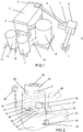
figure 2 presents the device for recycling mixed plastic waste according to the present invention with the location of the blade system shown; -
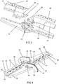
figure 3 presents the perspective view of the parts of the blade system according to the present invention; -
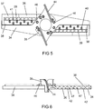
figure 4 presents the perspective view of the blade system according to the present invention; -
figure 5 presents the top view of the blade system depicted onfigure 4 ; -
figure 6 presents the side view of the blade system depicted onfigure 4 ; -
figure 7 presents the end view of the blade system depicted onfigure 4 ; -
figure 8 presents the perspective view of the mounting plate of the blade system blades; -
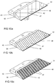
figures 9a to 9c present the outer blades of the blade system in case of various implementation examples; -
figures 10a to 10c present the inner blades of the blade system in case of various implementation examples. - The system for recycling unsorted mixed plastic waste into homogenised raw material mass of unidentified, unclean, and unsorted mixed plastic waste of different densities and low volume weight, presented in
figure 1 comprisesinput 1 for the mixed plastic waste,waste crusher 3, connected with theinput 1 via afeed conveyor 2,metal separator 4 connected with thewaste crusher 3,air separator 6 and collectingcontainer 7 connected with themetal separator 4 via thefirst conveyer 5, device for recycling mixedplastic waste 9 according to the present invention, connected with the collectingcontainer 7 via thesecond conveyor 8, after-cooler 11 connected with the device for recycling mixedplastic waste 9 via thethird conveyor 10,homogenization device 13 connected with the after-cooler 13 via thefourth conveyor 12, and anoutlet conveyor 14. - The system presented in
figure 1 performs the preliminary processing of mixed plastic waste, the method for recycling mixed plastic waste according to the present invention, and after-cooling of the granulated mass created from the mixed plastic waste in the course of recycling. An alternative solution of the method for recycling mixed plastic waste according to the present invention performs the preliminary processing of the mixed plastic waste outside the system presented infigure 1 , and they are routed directly to the device for recycling mixedplastic waste 9. - The device for recycling mixed
plastic waste 9 according to the present invention presented infigure 2 comprises anagglomeration chamber base 15,agglomeration chamber 16, equipped with adouble wall 17, observation and service opening 18 (for visual inspection by technical/maintenance personnel, and replacing of the blade system parts and double walls), and recycled plasticmixture outlet port 19,loading chamber 20 equipped with aloading port 21 and an upper observation opening 22,cooling system 23 equipped with the coolinginlet 24 and coolingoutlet 25,motor 26, transmission and lubricatingchamber 27,pre-heated lubricating pump 28,switchboard 29,collar 31 attached to the bottom 30 of theagglomeration chamber 16,shaft 32 running through the bottom 30 andcollar 31, and connected with themotor 26,blade system 33 according to the present invention attached to theshaft 32, and exhaust fan forwater vapour 52. - Due to the abrasiveness and high temperatures of the mixed plastic waste, an additional
double wall 17, manufactured of at least three parts has been provided for the inner wall of theagglomeration chamber 16 for higher wear resistance and durability, with its height greater than the thickness of belt of the mixed plastic waste being recycled, and the height to which the mixed plastic waste particles can be flown in the course of being crushed. To achieve better wear resistance, thedouble wall 17 has been manufactured of abrasion resistant material with a hardness of at least 450 HBW. - In the course of the melting process of the device for recycling mixed
plastic waste 9 unsorted, unidentified, and unclean mixed plastic waste is taken to melting temperature, at which the mixed plastic waste is mixed in a molten state, and the organic and bacterial material is destroyed during thermal processing. After the melting, mixing and thermal processing of the mixed plastic waste, the compaction process of the molten mixed plastic waste is performed. The compaction of the volume of up to approximately ten times is performed. The mass of mixed plastic waste taken to a molten state in the course of the melting process is rapidly cooled down by the spraying of approximately 2 to 3 litres of water, preferably to approximately 4 °C to 10 °C, causing the molten mass to harden. The blade system blades of the device for recycling mixed plastic waste that were initially mixing the molten mass now start to crush the hardened mass. -
Figures 3 to 7 present theblade system 33 of the device for recycling mixedplastic waste 9 according to the present invention, comprising ablade holder 34, two material exit guides 35, twoinner blades 36, twoouter blades 37, twoblade mounting plates 38, and fasteners (e.g. bolts) of theblade holder 34,material exit guide 35,blades plate 38. To achieve better wear resistance, the parts of theblade system 33 have been manufactured of abrasion resistant material with a hardness of at least 450 HBW. - The blade systems used by known solutions are not able to withstand the friction, high temperatures, vibration and high power; they quickly grow blunt and worn, and break. To solve this problem the parts of the blade system according to the present invention have been designed to be more durable; this has been achieved by using thicker blades with their cutting angles and construction different from the ones used by known solutions.
-
Figure 3 depicts the length L1 of theouter blade 37 of the blade system according to the present invention, and the side length L2 of the inner blade at the side towards theholder 34, that according to the preferred embodiment are approximately equal, L1 ≈ L2. If L1 > L2, theouter blade 37 would wear more quickly and more extensively, because according to the preferred representation theouter blade 37 works more intensively. If L1 < L2, partial uneven wearing of theinner blade 36 would occur. The fraction size decreases due to worn blades. The alternative representation of the invention has the same volume of theagglomeration chamber 16, but the quantity of the mixed plastic waste input for recycling has been increased, the length L1 has been increased, and the length L12 decreased, and L1 > L2; or the quantity of the mixed plastic waste input for recycling has been decreased, and in that case a blade system with L1 < L2 has been used. -
Figures 4 to 7 present various views of the assembled blade system according to the present invention. According to the preferred representation of the blade system the cutting surface of theblade mounting plates 38 has been hardfaced 39 to ensure melting and wear resistance. Welded strips ofhard metal 41 have been provided in front of the fastening holes 40 of the mountingplate 38 in the direction of rotation, preferably e.g. crescent-shaped. In contrast to the known solutions, to achieve larger impact forces, theinner blades 36 andouter blades 37 of the blade system have been attached to theblade holder 34 reversed, with the cutting surface of theblades 42 downwards toward theagglomeration chamber 16 bottom 30, and thebottom surface 43 of the blades upwards as depicted inFigures 3 to 7 . The material guides 35 are hardfaced 44. The material guides 35 have been attached to theblade holder 34 e.g. by welding and/or using a boltedconnection 45. Theblade system 33 has been attached to the shaft withbolts 46. Thecollar 31 has been attached to the bottom, and also welded in addition to the bolted connection. - To achieve better wear resistance, the cutting
surface 42 of theinner blades 36 andouter blades 37 has been hardfaced 47, and thecutting edge 48 of the blades has been blunted by hardfacing.Figures 9a to 9c present various preferred representations of the hardfaced cutting surfaces of theouter blades 37,figures 10a to 10c present various preferred representations of the hardfaced cutting surfaces of theinner blades 36; scale-like welding applied on the cutting surface of the blades is the most preferred due to its highest wear resistance (depicted onfigures 9c and10c ). To achieve higher durability, also other pattern-shaped hardfacing types are preferred, creating e.g. hardfaced stripes diagonal to thecutting edge 48 on the cutting surfaces of the blades (with its implementation example presented onfigures 9a and 9b ), or grooves formed by hardfacing, perpendicular to thecutting edge 48, with their implementation examples presented onfigures 10a and 10b . - In contrast to the known solutions having the blades cut the material being recycled, the reversed placement of the blades, blunted cutting
edge 48 and the cutting surface hardfaced with various patterns of the present invention achieve the effect of making theblades - The step of the rhombic weld pattern applied on the
blade mounting plate 38,outer blade 37 andinner blade 36, presented infigures 8 ,9a and10a , respectively, is approximately 20 to 30 mm. - This achieves higher durability and wear resistance with respect to temperature and friction. Such design of the blades also ensures uniform fragments when crushing the material being recycled.
- In contrast to generally known solutions, where the heads of the fasteners extend out of their holes, and as a result wearing quickly, the blades of the present invention have been thickened, creating deeper fastener holes, and allowing the tightened fastening bolts to remain coplanar to the surface of the blades.
- The cutting
angle α 49 of theblade mounting plate 38 presented onfigure 8 , and the cutting angle β 50 presented infigures 9a, 9c andfigures 10a to 10b are approximately 28-32°. Having the cutting angle within this range achieves the best crushing effect, and at the same time theblades blade mounting plate 38 last the longest. - The angle γ 51 between the cutting edge of the
inner blade 36, and the edge at the side of thematerial exit guide 35 is preferably approximately 50°. Theblades blade mounting plate 38 have shape and dimensions allowing the parts of theblade system 33 to form such a level/even surface by assembly of theblade system 33 that the mixed plastic waste material being crushed would be thrown away from the blade system surface, not slide and rub against it as it does according to the known solutions. Using such a construction achieves higher and better resistance to high temperatures and friction for the blade system and its parts. - In contrast to the known solutions the blades of the blade system of the present invention strike and crush the material instead of cutting it, and create a uniform fragment.
- The rotating speed of the
blade system 33 generated by themotor 26 is approximately 1200 rpm, and at the amperage of ca 600 A the temperature of approximately 160 °C is achieved in theagglomeration chamber 16 due to friction after the mixed plastic waste has been melted and mixed to a uniform mass at the temperature of approximately 150-160 °C; then the sprinkler is turned on. - To ensure higher productivity (kg/h) when using an
agglomeration chamber 16 of the same volume, a morepowerful motor 26 is used, enabling larger quantities of material to be input at a time (batch kg) and increasing the productivity (kg/h). The more powerful the motor used, the more durable must be the transmissions,blade system 33, and agglomeration chamber of the device for recycling mixed plastic waste. Different preferred alternative implementation examples for using motors of varying power while the volume of theagglomeration chamber 16 used remains the same are provided below.Implementation example 1 Implementation example 2 Implementation example 3 Motor (HP) 540 420-340 270-220 Drum size (mm) 200 1,200 1,200 Batch (kg) 100-150 75-120 60-80 Productivity (kg/h) 1,000-1,500 800-1,000 450-650 - One recycling cycle lasts approximately 5-15 minutes. The preferred representation of the solution according to the present invention uses the implementation example 2. When increased productivity is required, the input quantity of mixed plastic waste to be recycled is increased, the capacity of the motor is also increased, and the thickness of the belt of mixed plastic waste being recycled also increases due to centrifugal force; this brings about the need to extend the outer blade and shorten the inner blade. For example, when using an additional quantity of
ca 50 kg of mixed plastic waste to be recycled for the alternative representation of the present invention, the length L1 of theouter blade 37 has been increased by 25 mm, and the length L2 of theinner blade 36 has been decreased by 25 mm. - For other alternative representations the diameter of the
agglomeration chamber 16 has been changed. For example, when the diameter of theagglomeration chamber 16 is increased or decreased by x percent, the length, thickness, and width of the parts of theblade system 33 are proportionally increased or decreased by x percent, whereas the distance between theouter blade 37 of theblade system 33, and the innerdouble wall 17 of the agglomeration chamber is approximately equal to the thickness of the blade. The larger this gap the more untreated material will end up inside it. When the distance between theouter blade 37 of theblade system 33, and the innerdouble wall 17 of the chamber is less than the approximate blade thickness, the blade could come into contact with the casing due to the temperature rising and parts expanding, making the gap smaller. - In contrast to the known solutions, using riveted connections for the inner walls of the
agglomeration chamber 16, the inner walls of theagglomeration chamber 16 of the present invention are provided with bolted connections. - The material guides 35 of the
blade system 33 route the material to the impact zone of theblades - Achieving 160 °C depends on the moisture content of the material, the ambient temperature, and the productivity.
- The temperature of the material is 180-190 °C at the
agglomeration chamber 16 temperature of 160 °C; mostly the mixed plastic waste is melted into a uniform mass at that temperature. The mixed plastic is not yet overheated. Raising the temperature of the agglomeration chamber to 180 °C creates the danger of overheating the plastic, and the properties of the plastic required for subsequent processing of the polymers deteriorate (its elasticity, toughness, and strength are decreased, and it becomes brittle). - In contrast to the known solutions more fasteners, e.g. bolts have been provided for attaching the
collar 31, and the collar has been additionally welded for the attachment to endure, to achieve better resistance to the vibration occurring during the recycling process. - The system presented in
figure 1 performs preliminary crushing 3 of the mixed plastic waste during preliminary processing; after that metal separation with themagnetic separator 4 takes place; then the waste is taken to theair separator 6 with theconveyor 5 for separating non-plastic material; the broken up plastic waste with metals and other non-plastic materials separated from it is subsequently taken to the collectingcontainer 7, and from there to the device for recycling mixedplastic waste 9 on theconveyor 8 for recycling through mixing, melting and crushing, involving disinfection of the bacterial and organic materials, and the compacting process of the mixed plastic waste at their melting temperature; the plastic mass obtained by recycling is taken to the after-cooler 11 from the device for recycling mixedplastic waste 9, and to thehomogenisation system 13 following the after-cooling. - The
waste crusher 3 or the pre-crushing system ensures efficient preliminary crushing of the mixed plastic waste. The speed of thefeed conveyor 2 for transporting the waste to thepre-crusher 3 is appropriately adjusted to maintain uniform input flow to thepre-crusher 3 according to the waste spreading productivity. A magnetic separator separating metals from the crushed mixed plastic waste is used as themetal separator 4. The capacity of themetal separator 4 has been chosen as optimal for the material flow coming from the crusher. Thefirst conveyor line 5 transports the crushed mixed plastic waste to the subsequent stage at theair separator 6. Non-polymer substances mixed with the plastic, for example sand, glass, nonferrous metals (aluminium, copper), minerals etc. are separated using theair separator 6. This does not involve separation of the mixed plastic by polymer types. The air separation stage also involves the initial mixing of the mixed plastic waste. Due to the large cubic content of the mixed plastic waste the crushed mixed plastic waste is transported to the collectingcontainer 7, equipped with automatic conveyors for moving the crushed plastic waste. The purpose of the collectingcontainer 7 is to create a raw material buffer preferably holding 3-4 tons of material. Thesecond conveyor line 8 controls the transportation of the mixed plastic waste to the compacting and sanitation stage of the mixed plastic waste recycling process according to the present invention in the device for recycling mixedplastic waste 9. - The method for recycling mixed plastic waste according to the present invention includes preliminary processing of the mixed plastic waste, routing of the pre-processed mixed plastic waste to the device for recycling mixed
plastic waste 9, recycling of the mixed plastic waste in thedevice 9 by heating, melting, mixing, reducing the cubic content of the recycled material, rapid cooling with tempering, crushing, and additional after-cooling and homogenisation. The device for recycling mixedplastic waste 9 performs thermal processing of the material, the melting process and finally crushing of the material recycled from the mixed plastic waste into granules. The device for recycling mixedplastic waste 9 reduces the cubic content of the mixed plastic waste, increases their density, processes the mixed plastic waste mechanically and thermally until melted, and mixes the mixed plastic waste in a molten state, thereat also eliminating the organic and bacterial input, rapidly cools down the plastic mass obtained by melting and mixing until it hardens, crushes the hardened plastic mass into particles, and routes it to after-cooling and homogenisation. The recycled plastic mixture obtained has a fragment size of approximately 3-10 mm, moisture content below 1%, and is stable raw material for the subsequent production process characterized by its melt flow index, melting temperature, density, and granule size. - Then the granules are transported to the after-cooling
system 11 using thecyclone conveyor 10, as the material is output from the production process at a temperature exceeding 100 degrees due to high temperatures generated by the production process of the device for recycling mixed plastic waste. The known solutions route the compacted clean materials recycled from single-type plastic to subsequent regranulate production; according to the present invention the material passes through an additional several-hour cooling cycle in the cooling tower. The after-cooler 11 is designed to preserve the plastic properties and fraction of the material. Following the after-cooling, the material is taken to thehomogenisation system 13 on theconveyor 12 where mixing of the material takes place. Thehomogenisation system 13 comprises a container mixer of at least 28 m3, enabling the mixing of the materials with each other and the homogenisation of the raw material mixture by batches of at least 10 to 15 tons. Unlike known container mixers, an inflow of warm air has been added to the container mixer of the present solution, to also achieve efficient drying along with the mixing. - As a result of the high temperature created in the course of the mixed plastic waste recycling process, the plastic mass recycled from mixed plastic waste is output at the temperature of approximately 115 °C to 165 °C. Unlike the generally known processes that route the compacted clean single-type plastics to subsequent regranulate production, according to the present invention the material passes through an additional several-hour cooling cycle in the
cooling tower 11, during which the material is mixed, and gradually cooled, this way stabilising the properties of the recycled polymer mixture for the subsequent production cycle. The material is after-cooled to the temperature of approximately 30-40 °C. - During the recycling stage the
blade system 33 of the device for recycling mixed plastic waste is started in thede vice 9 with the help of themotor 26 at the approximate rotation speed of 1200 rpm. The mixed plastic waste to be recycled in a quantity of 60-150 kg is taken in theagglomeration chamber 16 via theinlet opening 21. The mixed plastic waste is crushed by theblade system 33, at the same time mixing it; the mixed plastic waste starts to heat and melt due to friction. The mixed plastic waste starts to melt at the temperature of approximately 140-150 °C, the amperage of themotor 26 is approximately 400 A. The temperature rises to approximately 160 °C in the agglomeration chamber, and the amperage increases to 600 A. Upon achieving this, about 2-3 litres of cold water is sprayed, instantly lowering the temperature to about 80 °C. Theblade system 33 continues to rotate at the same time. - The exhaust fan for
water vapour 52 is started before spraying the water. The molten mass hardens as the water is sprayed, and the blades still rotating start to crush the hardened mass. The temperature starts to rise again, and theoutlet port 19 is opened at the temperature of 100-110 °C. The amperage starts to rise as well and will increase to 600 amperes. The crushed fragments of the recycled mixed plastic waste are taken from theagglomeration chamber 16 of the device for recycling mixedplastic waste 9 to cool down in the cyclone of the after-cooler 9 by using centrifugal force, to make the material release heat into the air, not coming in contact with any other materials.
Claims (13)
- A device for recycling mixed plastic waste (9), comprising an agglomeration chamber base (15), agglomeration chamber (16), observation and service opening (18), recycled plastic mixture outlet port (19), loading chamber (20) equipped with a loading port (21) and an upper observation opening (22), motor (26), switchboard (29), collar (31) attached to the bottom (30) of the agglomeration chamber (16), shaft (32) running through the bottom (30) and collar (31), and attached to the motor (26), blade system (33) comprising blade holder (34), two material exit guides (35), two inner blades (36), two outer blades (37), two blade mounting plates (38), and fasteners attached to the shaft (32), exhaust fan for water vapour (52), is characterised in that closed bearings and pressure seals have been provided for the bearing pedestal of the shaft (32), the agglomeration chamber (16) comprises a double wall (17), and the equipment is provided with a cooling system (23) equipped with a cooling inlet (24) and cooling outlet (25), transmission and lubricating chamber (27), and lubricating pump (28), equipped with an additional preheater and the cutting angle α (49) and the cutting angle β (50) of the mounting plate (38) are approximately 28° to 32°, the angle γ (51) between the cutting edge of the inner blade (36), and the edge on the side of the material exit guide (35) is approximately 50°.
- The device according to claim 1 is characterised in that the double wall (17) comprises at least three replaceable parts with their height greater than the thickness of the belt of the mixed plastic waste being recycled in the agglomeration chamber (16), and the potential height to which the mixed plastic waste particles can be thrown in the course of the crushing process.
- The device according to claim 1 is characterised in that the rotation speed of the blade system (33) is approximately 1200 rpm during the recycling process, the amperage is approximately 600 A, and the temperature in the agglomeration chamber (16) is approximately 140 °C to 160 °C.
- The device according to claim 1 is characterised in that one recycling cycle lasts approximately 5-15 minutes.
- The device according to claim 1 is characterised in that the distance between the outer blade (37) of the blade system (33) and the double wall (17) of the agglomeration chamber (16) is approximately equal to the thickness of the blade.
- The device according to claim 1 is characterised in that the cutting surface (42) of the blades (36) and (37) has been hardfaced (47), and the cutting edge (48) of the blades (36) and (37) has been blunted by hardfacing.
- The device according to claim 1 is characterised in that the cutting surface (42) of mounting plates (38) of the blade system blades has been hardfaced (39), and hardfacing has been provided in front of the fastening holes (40) of the mounting plate (38) in the rotating direction.
- The device according to claim 1 is characterised in that the material guides (35) have been hardfaced (44).
- A method for recycling mixed plastic waste involves the preliminary processing of the mixed plastic waste, the routing of the pre-processed mixed plastic waste to a device for recycling mixed plastic waste according to claim 1, the recycling of the mixed plastic waste in the device (9) by heating, melting, mixing, reducing the cubic content of the recycled material, cooling, crushing, and post-processing, characterised in that the mixed plastic waste is mixed in a molten state, and the organic and bacterial material is destroyed during the thermal processing, and that the method for recycling mixed plastic waste includes the following stages:- the blade system (33) of the device for recycling mixed plastic waste is started at the approximate rotation speed of 1200 rpm;- the mixed plastic waste to be recycled in a quantity of 60-150 kg is taken to the agglomeration chamber (16);- the mixed plastic waste is crushed using the blade system (33) by simultaneously mixing, heating and melting it at the temperature of approximately 140-150 °C, and achieving the amperage of approximately 400 A for the motor (26);- the temperature is increased to the level of approximately 150 °C to 160 °C, and the amperage to 600 A, and the plastic mass obtained is rapidly cooled down to harden when this level is achieved;- crushing of the hardened mass is started;- increasing of the temperature and amperage is started;- the outlet port (19) is opened at the temperature of 100-110 °C;- the amperage is increased to 600 amperes;- the crushed recycled mixed plastic waste fragments are routed from the agglomeration chamber (16) to the after-cooler (9);- the plastic mass is taken to homogenisation from the after-cooler (9).
- The method according to claim 9 is characterised in that water at the temperature of approximately 4 °C - 10 °C, and in quantity of 2 to 3 litres is sprayed for rapid cooling, decreasing the temperature instantly to approximately 80 °C.
- The method according to claim 9 is characterised in that as a result of the high temperature created in the course of the mixed plastic waste recycling process, the temperature of the output plastic mass is approximately 115 °C to 165 °C.
- The method according to claim 9 is characterised in that the fraction of the recycled plastic mixture has uniform size between 3-10 mm, and moisture content below 1%.
- The method according to claim 9 is characterised in that compacting of the volume approximately up to ten times is performed.
Priority Applications (2)
| Application Number | Priority Date | Filing Date | Title |
|---|---|---|---|
| EP14168154.4A EP2944445B1 (en) | 2014-05-13 | 2014-05-13 | Device and a method for recycling mixed plastic waste |
| US14/299,540 US9815225B2 (en) | 2014-05-13 | 2014-06-09 | Device for recycling mixed plastic waste, a blade system for said device and a method for recycling mixed plastic waste |
Applications Claiming Priority (1)
| Application Number | Priority Date | Filing Date | Title |
|---|---|---|---|
| EP14168154.4A EP2944445B1 (en) | 2014-05-13 | 2014-05-13 | Device and a method for recycling mixed plastic waste |
Publications (2)
| Publication Number | Publication Date |
|---|---|
| EP2944445A1 EP2944445A1 (en) | 2015-11-18 |
| EP2944445B1 true EP2944445B1 (en) | 2017-03-22 |
Family
ID=50842033
Family Applications (1)
| Application Number | Title | Priority Date | Filing Date |
|---|---|---|---|
| EP14168154.4A Active EP2944445B1 (en) | 2014-05-13 | 2014-05-13 | Device and a method for recycling mixed plastic waste |
Country Status (2)
| Country | Link |
|---|---|
| US (1) | US9815225B2 (en) |
| EP (1) | EP2944445B1 (en) |
Cited By (1)
| Publication number | Priority date | Publication date | Assignee | Title |
|---|---|---|---|---|
| CN110421745A (en) * | 2019-08-14 | 2019-11-08 | 虞刚 | A kind of house refuse polybag separation platform |
Families Citing this family (22)
| Publication number | Priority date | Publication date | Assignee | Title |
|---|---|---|---|---|
| US11260437B2 (en) * | 2016-11-22 | 2022-03-01 | Brian Michael Hays | Cleaning and separating medical waste |
| CN107525914A (en) * | 2017-07-18 | 2017-12-29 | 浙江三信智能机械科技有限公司 | Discharge testing machine |
| US10639640B2 (en) * | 2017-10-23 | 2020-05-05 | MedReleaf Corp. | Apparatus and methods for the comminution of botanical feedstock |
| CN108262135B (en) * | 2018-01-25 | 2020-05-29 | 深鹏环保工程有限公司 | Multifunctional solid waste comprehensive utilization equipment |
| CN109986717B (en) * | 2019-04-26 | 2021-01-19 | 云浮市铧鑫五金塑料制品有限公司 | Engineering plastic recovery processing device |
| CN113748005A (en) * | 2019-04-29 | 2021-12-03 | 西斯尔·亚历山大·西蒙·维尔弗罗因德 | Composite panels from plastic waste |
| CN110181721A (en) * | 2019-06-11 | 2019-08-30 | 刘丽华 | A kind of PET bottle essence crushing recyclable device |
| CN110341088B (en) * | 2019-08-05 | 2021-06-01 | 丰城市小标杆新材料有限公司 | Polystyrene foam packing carton retrieves processing system of recycling |
| CN110586258B (en) * | 2019-08-24 | 2021-06-15 | 武汉宇格电力设备有限公司 | Planetary ball mill for industrial use |
| CN111516181B (en) * | 2020-04-03 | 2021-10-26 | 苏州爱柯基科技有限公司 | Glass glues shell recovery unit |
| CN112705552B (en) * | 2020-12-10 | 2023-11-21 | 江苏中清新型材料有限公司 | Production facility with melt-blown cloth garbage collection recycles |
| CN112694654A (en) * | 2020-12-22 | 2021-04-23 | 安徽杰蓝特新材料有限公司 | Antibacterial color master batch applied to PE water supply pipe and preparation method thereof |
| CN112808408A (en) * | 2020-12-30 | 2021-05-18 | 南京顺接商贸有限公司 | Building waste breaker |
| WO2022147527A1 (en) * | 2021-01-04 | 2022-07-07 | Chz Technologies, Llc | Methods and systems for destruction of synthetic per- and polyfluoro compounds |
| US11286832B1 (en) | 2021-04-07 | 2022-03-29 | Scuderi Group, Inc. | Bottoming cycle power system |
| CN113276317A (en) * | 2021-05-18 | 2021-08-20 | 付志新 | Medical seaming ware cloth plastic separation recovery processing equipment |
| US11346256B1 (en) * | 2021-06-25 | 2022-05-31 | Scuderi Group, Inc. | Systems and methods associated with bottoming cycle power systems for generating power, capturing carbon dioxide and producing products |
| US20230312438A1 (en) * | 2022-04-01 | 2023-10-05 | Chevron U.S.A. Inc. | Circular economy for plastic waste to polyethylene and base oil via refinery crude unit |
| US20230312437A1 (en) * | 2022-04-01 | 2023-10-05 | Chevron U.S.A. Inc. | Circular economy for plastic waste to polypropylene via refinery fcc unit |
| WO2023192439A1 (en) * | 2022-04-01 | 2023-10-05 | Chevron U.S.A. Inc. | Circular economy for plastic waste to polyethylene via refinery fcc unit |
| US11639677B1 (en) | 2022-09-22 | 2023-05-02 | Scuderi Group, Inc. | System and methods for capturing carbon dioxide from a flow of exhuast gas from a combustion process |
| CN117696587B (en) * | 2024-02-06 | 2024-04-09 | 河北省多基复合材料产业技术研究院有限公司 | Recovery device based on retired fan blade and method for obtaining glass fiber |
Family Cites Families (23)
| Publication number | Priority date | Publication date | Assignee | Title |
|---|---|---|---|---|
| US2186716A (en) * | 1937-09-11 | 1940-01-09 | Charles W Dieckmann | Cutter for meat grinders |
| US2259623A (en) * | 1940-10-14 | 1941-10-21 | Charles W Dieckmann | Rotary cutter |
| DE3231237A1 (en) | 1982-08-23 | 1984-02-23 | Dr. Herfeld GmbH & Co KG, 5982 Neuenrade | METHOD FOR COMPRESSING THERMOPLASTIC PLASTIC MATERIAL |
| US5184780A (en) * | 1988-07-18 | 1993-02-09 | First Dominion Holdings, Inc. | Solid waste disposal |
| US5042730A (en) * | 1990-05-17 | 1991-08-27 | Hundt Vincent G | Multi-purpose rotating disc shredding device |
| AT396900B (en) * | 1992-03-19 | 1993-12-27 | Erema | DEVICE FOR PRETREATING THERMOPLASTIC PLASTIC |
| DE4217005C2 (en) * | 1992-05-22 | 1994-03-03 | Himont Inc | Process for recovering plastic from painted plastic parts |
| DE4236446A1 (en) * | 1992-10-28 | 1994-05-05 | Herfeld Gmbh & Co Kg Dr | Process for the production of a recyclable agglomerate from plastic waste |
| DE4301066A1 (en) * | 1993-01-16 | 1994-07-21 | Igu Umweltschutzanlagen | Method and device for processing plastic waste |
| US5271442B1 (en) * | 1993-02-19 | 1996-05-07 | Commercial Knife Inc | Knife with clamp package mounting knife |
| DE19500224A1 (en) | 1995-01-05 | 1996-07-18 | Dietmar Guschall | Process for the preparation of mixed plastics |
| AU7622696A (en) * | 1995-11-11 | 1997-06-05 | Schafer Elektrotechnik - Sondermaschinen | Process and device for the processing of components from mixed materials and other building materials mixed therewith and the use thereof |
| IT1291465B1 (en) * | 1997-01-24 | 1999-01-11 | So Ti S R L | PROCEDURE AND EQUIPMENT FOR THE TREATMENT OF SOLID MATRIX WASTE CONTAINING VAPORISABLE SUBSTANCES. |
| AT410298B (en) * | 2001-06-11 | 2003-03-25 | Bacher Helmut | DEVICE FOR FILLING A SNAIL STORED IN A CASE AND METHOD FOR OPERATING SUCH A DEVICE |
| GB2377900B (en) * | 2002-05-03 | 2003-06-18 | John Alan Porter | Treatment of municipal solid waste |
| AT411038B (en) | 2002-06-10 | 2003-09-25 | Bacher Helmut | Mixer for homogenization of recycled PET materials has angled blades to lift and disperse material below the tool and blade carrier disc |
| US7278598B2 (en) * | 2004-01-23 | 2007-10-09 | Vita-Mix Corporation | Blender blade |
| US7562836B2 (en) * | 2004-05-03 | 2009-07-21 | Jody Langston | Apparatus, system, and method for condensing, separating and storing recyclable material |
| DE102007062321A1 (en) * | 2007-12-21 | 2009-06-25 | Mws Schneidwerkzeuge Gmbh & Co. Kg | Exchangeable prism shaped fly cutter for milling device of plastic agglomerator, has deflector surfaces forming edges at rear side of cutter, where edges are inclinedly arranged opposite to upper side of cutter at inclination angle |
| AT508951B1 (en) * | 2009-04-17 | 2012-03-15 | Erema | METHOD AND ARRANGEMENT FOR RECYCLING PLASTIC |
| US20110286844A1 (en) * | 2010-02-08 | 2011-11-24 | Mitsubishi Heavy Industries, Ltd. | Lubricant heating mechanism, gear mechanism , and wind turbine generator using the same |
| US8444076B2 (en) * | 2010-09-30 | 2013-05-21 | Vita-Mix Corporation | Blender blade |
| US8567702B2 (en) * | 2011-02-09 | 2013-10-29 | Wisconsin Film & Bag, Inc. | Post consumer scrap film recycling process |
-
2014
- 2014-05-13 EP EP14168154.4A patent/EP2944445B1/en active Active
- 2014-06-09 US US14/299,540 patent/US9815225B2/en active Active
Non-Patent Citations (1)
| Title |
|---|
| None * |
Cited By (1)
| Publication number | Priority date | Publication date | Assignee | Title |
|---|---|---|---|---|
| CN110421745A (en) * | 2019-08-14 | 2019-11-08 | 虞刚 | A kind of house refuse polybag separation platform |
Also Published As
| Publication number | Publication date |
|---|---|
| EP2944445A1 (en) | 2015-11-18 |
| US9815225B2 (en) | 2017-11-14 |
| US20150258713A1 (en) | 2015-09-17 |
Similar Documents
| Publication | Publication Date | Title |
|---|---|---|
| EP2944445B1 (en) | Device and a method for recycling mixed plastic waste | |
| KR101773223B1 (en) | Composite material from waste and at least one element of vulcanized rubber and tire cords | |
| KR101753105B1 (en) | Recyclables wastes crusher | |
| EP2186942A1 (en) | Method of replacing artificial lawn and artificial lawn disposal apparatus | |
| JPH0985212A (en) | Preparation of crushed automobile residue - synthetic resin mixture | |
| EP3003668B1 (en) | A system and a method for processing plastic | |
| US20200199324A1 (en) | Reconstituted composite materials derived from waste made by solid state pulverization | |
| CN1988991A (en) | Method for processing plastic waste to obtain matrix material, the matrix material and the composite material | |
| KR100879929B1 (en) | Apparatus for melting waste forming plastic | |
| US10301448B2 (en) | Polymer composition from mixed plastic waste | |
| US5482216A (en) | Method for reclaiming plastic which contains undesirable contaminants | |
| KR20170006471A (en) | Creshing Deduster Of Municipal Waste Manufacturing System | |
| WO2008135757A1 (en) | Waste processing apparatus and methods | |
| US20180257081A1 (en) | Method and system for recycling rubber | |
| KR20220145966A (en) | Waste Synthetic Resin Regenerative Extrusion Unit with two Mixing Zone and Vents | |
| KR20190115605A (en) | A regeneration device equipped with high frequency heating unit of two kinds of resin and a regeneration method thereof | |
| Daborn et al. | Cryogenic communition in scrap recycling | |
| KR20190043722A (en) | Waste carpet reproduction device | |
| JP2009084517A (en) | Compression solidification method and compression solidification apparatus of waste plastic | |
| BR112021004191A2 (en) | method and system for forming a composite material | |
| JP4050029B2 (en) | Waste treatment system | |
| JP5165271B2 (en) | Coking method for metallurgy using waste plastic molding | |
| KR100715482B1 (en) | A disposal equipment for scrap synthetic resins | |
| WO2022091134A1 (en) | A system for manufacturing wood from mix plastic waste | |
| EP2323824B1 (en) | Device and method for cooling solid particles |
Legal Events
| Date | Code | Title | Description |
|---|---|---|---|
| PUAI | Public reference made under article 153(3) epc to a published international application that has entered the european phase |
Free format text: ORIGINAL CODE: 0009012 |
|
| AK | Designated contracting states |
Kind code of ref document: A1 Designated state(s): AL AT BE BG CH CY CZ DE DK EE ES FI FR GB GR HR HU IE IS IT LI LT LU LV MC MK MT NL NO PL PT RO RS SE SI SK SM TR |
|
| AX | Request for extension of the european patent |
Extension state: BA ME |
|
| 17P | Request for examination filed |
Effective date: 20160111 |
|
| RBV | Designated contracting states (corrected) |
Designated state(s): AL AT BE BG CH CY CZ DE DK EE ES FI FR GB GR HR HU IE IS IT LI LT LU LV MC MK MT NL NO PL PT RO RS SE SI SK SM TR |
|
| 17Q | First examination report despatched |
Effective date: 20160426 |
|
| RAP1 | Party data changed (applicant data changed or rights of an application transferred) |
Owner name: ROLAN INVESTMENT OUE |
|
| GRAJ | Information related to disapproval of communication of intention to grant by the applicant or resumption of examination proceedings by the epo deleted |
Free format text: ORIGINAL CODE: EPIDOSDIGR1 |
|
| GRAP | Despatch of communication of intention to grant a patent |
Free format text: ORIGINAL CODE: EPIDOSNIGR1 |
|
| RIC1 | Information provided on ipc code assigned before grant |
Ipc: F16H 57/04 20060101ALN20160928BHEP Ipc: B02C 18/08 20060101ALI20160928BHEP Ipc: B29B 17/04 20060101AFI20160928BHEP Ipc: B29B 9/00 20060101ALI20160928BHEP Ipc: B29B 17/00 20060101ALN20160928BHEP Ipc: B02C 18/18 20060101ALI20160928BHEP |
|
| INTG | Intention to grant announced |
Effective date: 20161018 |
|
| GRAS | Grant fee paid |
Free format text: ORIGINAL CODE: EPIDOSNIGR3 |
|
| STAA | Information on the status of an ep patent application or granted ep patent |
Free format text: STATUS: GRANT OF PATENT IS INTENDED |
|
| GRAA | (expected) grant |
Free format text: ORIGINAL CODE: 0009210 |
|
| STAA | Information on the status of an ep patent application or granted ep patent |
Free format text: STATUS: THE PATENT HAS BEEN GRANTED |
|
| AK | Designated contracting states |
Kind code of ref document: B1 Designated state(s): AL AT BE BG CH CY CZ DE DK EE ES FI FR GB GR HR HU IE IS IT LI LT LU LV MC MK MT NL NO PL PT RO RS SE SI SK SM TR |
|
| REG | Reference to a national code |
Ref country code: GB Ref legal event code: FG4D |
|
| REG | Reference to a national code |
Ref country code: CH Ref legal event code: EP |
|
| REG | Reference to a national code |
Ref country code: AT Ref legal event code: REF Ref document number: 877273 Country of ref document: AT Kind code of ref document: T Effective date: 20170415 |
|
| REG | Reference to a national code |
Ref country code: IE Ref legal event code: FG4D |
|
| REG | Reference to a national code |
Ref country code: DE Ref legal event code: R096 Ref document number: 602014007746 Country of ref document: DE |
|
| REG | Reference to a national code |
Ref country code: FR Ref legal event code: PLFP Year of fee payment: 4 |
|
| REG | Reference to a national code |
Ref country code: CH Ref legal event code: NV Representative=s name: GEVERS SA, CH |
|
| REG | Reference to a national code |
Ref country code: NL Ref legal event code: MP Effective date: 20170322 |
|
| PG25 | Lapsed in a contracting state [announced via postgrant information from national office to epo] |
Ref country code: NO Free format text: LAPSE BECAUSE OF FAILURE TO SUBMIT A TRANSLATION OF THE DESCRIPTION OR TO PAY THE FEE WITHIN THE PRESCRIBED TIME-LIMIT Effective date: 20170622 Ref country code: LT Free format text: LAPSE BECAUSE OF FAILURE TO SUBMIT A TRANSLATION OF THE DESCRIPTION OR TO PAY THE FEE WITHIN THE PRESCRIBED TIME-LIMIT Effective date: 20170322 Ref country code: FI Free format text: LAPSE BECAUSE OF FAILURE TO SUBMIT A TRANSLATION OF THE DESCRIPTION OR TO PAY THE FEE WITHIN THE PRESCRIBED TIME-LIMIT Effective date: 20170322 Ref country code: HR Free format text: LAPSE BECAUSE OF FAILURE TO SUBMIT A TRANSLATION OF THE DESCRIPTION OR TO PAY THE FEE WITHIN THE PRESCRIBED TIME-LIMIT Effective date: 20170322 Ref country code: GR Free format text: LAPSE BECAUSE OF FAILURE TO SUBMIT A TRANSLATION OF THE DESCRIPTION OR TO PAY THE FEE WITHIN THE PRESCRIBED TIME-LIMIT Effective date: 20170623 |
|
| REG | Reference to a national code |
Ref country code: LT Ref legal event code: MG4D |
|
| REG | Reference to a national code |
Ref country code: AT Ref legal event code: MK05 Ref document number: 877273 Country of ref document: AT Kind code of ref document: T Effective date: 20170322 |
|
| PG25 | Lapsed in a contracting state [announced via postgrant information from national office to epo] |
Ref country code: LU Free format text: LAPSE BECAUSE OF NON-PAYMENT OF DUE FEES Effective date: 20170531 Ref country code: LV Free format text: LAPSE BECAUSE OF FAILURE TO SUBMIT A TRANSLATION OF THE DESCRIPTION OR TO PAY THE FEE WITHIN THE PRESCRIBED TIME-LIMIT Effective date: 20170322 Ref country code: SE Free format text: LAPSE BECAUSE OF FAILURE TO SUBMIT A TRANSLATION OF THE DESCRIPTION OR TO PAY THE FEE WITHIN THE PRESCRIBED TIME-LIMIT Effective date: 20170322 Ref country code: RS Free format text: LAPSE BECAUSE OF FAILURE TO SUBMIT A TRANSLATION OF THE DESCRIPTION OR TO PAY THE FEE WITHIN THE PRESCRIBED TIME-LIMIT Effective date: 20170322 Ref country code: BG Free format text: LAPSE BECAUSE OF FAILURE TO SUBMIT A TRANSLATION OF THE DESCRIPTION OR TO PAY THE FEE WITHIN THE PRESCRIBED TIME-LIMIT Effective date: 20170622 |
|
| PG25 | Lapsed in a contracting state [announced via postgrant information from national office to epo] |
Ref country code: NL Free format text: LAPSE BECAUSE OF FAILURE TO SUBMIT A TRANSLATION OF THE DESCRIPTION OR TO PAY THE FEE WITHIN THE PRESCRIBED TIME-LIMIT Effective date: 20170322 |
|
| PG25 | Lapsed in a contracting state [announced via postgrant information from national office to epo] |
Ref country code: ES Free format text: LAPSE BECAUSE OF FAILURE TO SUBMIT A TRANSLATION OF THE DESCRIPTION OR TO PAY THE FEE WITHIN THE PRESCRIBED TIME-LIMIT Effective date: 20170322 Ref country code: IT Free format text: LAPSE BECAUSE OF FAILURE TO SUBMIT A TRANSLATION OF THE DESCRIPTION OR TO PAY THE FEE WITHIN THE PRESCRIBED TIME-LIMIT Effective date: 20170322 Ref country code: SK Free format text: LAPSE BECAUSE OF FAILURE TO SUBMIT A TRANSLATION OF THE DESCRIPTION OR TO PAY THE FEE WITHIN THE PRESCRIBED TIME-LIMIT Effective date: 20170322 Ref country code: RO Free format text: LAPSE BECAUSE OF FAILURE TO SUBMIT A TRANSLATION OF THE DESCRIPTION OR TO PAY THE FEE WITHIN THE PRESCRIBED TIME-LIMIT Effective date: 20170322 Ref country code: AT Free format text: LAPSE BECAUSE OF FAILURE TO SUBMIT A TRANSLATION OF THE DESCRIPTION OR TO PAY THE FEE WITHIN THE PRESCRIBED TIME-LIMIT Effective date: 20170322 Ref country code: CZ Free format text: LAPSE BECAUSE OF FAILURE TO SUBMIT A TRANSLATION OF THE DESCRIPTION OR TO PAY THE FEE WITHIN THE PRESCRIBED TIME-LIMIT Effective date: 20170322 |
|
| REG | Reference to a national code |
Ref country code: EE Ref legal event code: FG4A Ref document number: E014263 Country of ref document: EE Effective date: 20170630 |
|
| PG25 | Lapsed in a contracting state [announced via postgrant information from national office to epo] |
Ref country code: PT Free format text: LAPSE BECAUSE OF FAILURE TO SUBMIT A TRANSLATION OF THE DESCRIPTION OR TO PAY THE FEE WITHIN THE PRESCRIBED TIME-LIMIT Effective date: 20170724 Ref country code: PL Free format text: LAPSE BECAUSE OF FAILURE TO SUBMIT A TRANSLATION OF THE DESCRIPTION OR TO PAY THE FEE WITHIN THE PRESCRIBED TIME-LIMIT Effective date: 20170322 Ref country code: IS Free format text: LAPSE BECAUSE OF FAILURE TO SUBMIT A TRANSLATION OF THE DESCRIPTION OR TO PAY THE FEE WITHIN THE PRESCRIBED TIME-LIMIT Effective date: 20170722 Ref country code: SM Free format text: LAPSE BECAUSE OF FAILURE TO SUBMIT A TRANSLATION OF THE DESCRIPTION OR TO PAY THE FEE WITHIN THE PRESCRIBED TIME-LIMIT Effective date: 20170322 |
|
| REG | Reference to a national code |
Ref country code: DE Ref legal event code: R097 Ref document number: 602014007746 Country of ref document: DE |
|
| PLBE | No opposition filed within time limit |
Free format text: ORIGINAL CODE: 0009261 |
|
| STAA | Information on the status of an ep patent application or granted ep patent |
Free format text: STATUS: NO OPPOSITION FILED WITHIN TIME LIMIT |
|
| PG25 | Lapsed in a contracting state [announced via postgrant information from national office to epo] |
Ref country code: MC Free format text: LAPSE BECAUSE OF FAILURE TO SUBMIT A TRANSLATION OF THE DESCRIPTION OR TO PAY THE FEE WITHIN THE PRESCRIBED TIME-LIMIT Effective date: 20170322 Ref country code: DK Free format text: LAPSE BECAUSE OF FAILURE TO SUBMIT A TRANSLATION OF THE DESCRIPTION OR TO PAY THE FEE WITHIN THE PRESCRIBED TIME-LIMIT Effective date: 20170322 |
|
| 26N | No opposition filed |
Effective date: 20180102 |
|
| PG25 | Lapsed in a contracting state [announced via postgrant information from national office to epo] |
Ref country code: SI Free format text: LAPSE BECAUSE OF FAILURE TO SUBMIT A TRANSLATION OF THE DESCRIPTION OR TO PAY THE FEE WITHIN THE PRESCRIBED TIME-LIMIT Effective date: 20170322 |
|
| PG25 | Lapsed in a contracting state [announced via postgrant information from national office to epo] |
Ref country code: LU Free format text: LAPSE BECAUSE OF NON-PAYMENT OF DUE FEES Effective date: 20170513 |
|
| REG | Reference to a national code |
Ref country code: FR Ref legal event code: PLFP Year of fee payment: 5 |
|
| REG | Reference to a national code |
Ref country code: CH Ref legal event code: NV Representative=s name: BOVARD SA NEUCHATEL CONSEILS EN PROPRIETE INTE, CH |
|
| PG25 | Lapsed in a contracting state [announced via postgrant information from national office to epo] |
Ref country code: HU Free format text: LAPSE BECAUSE OF FAILURE TO SUBMIT A TRANSLATION OF THE DESCRIPTION OR TO PAY THE FEE WITHIN THE PRESCRIBED TIME-LIMIT; INVALID AB INITIO Effective date: 20140513 |
|
| PG25 | Lapsed in a contracting state [announced via postgrant information from national office to epo] |
Ref country code: CY Free format text: LAPSE BECAUSE OF FAILURE TO SUBMIT A TRANSLATION OF THE DESCRIPTION OR TO PAY THE FEE WITHIN THE PRESCRIBED TIME-LIMIT Effective date: 20170322 |
|
| PG25 | Lapsed in a contracting state [announced via postgrant information from national office to epo] |
Ref country code: MK Free format text: LAPSE BECAUSE OF FAILURE TO SUBMIT A TRANSLATION OF THE DESCRIPTION OR TO PAY THE FEE WITHIN THE PRESCRIBED TIME-LIMIT Effective date: 20170322 |
|
| PG25 | Lapsed in a contracting state [announced via postgrant information from national office to epo] |
Ref country code: TR Free format text: LAPSE BECAUSE OF FAILURE TO SUBMIT A TRANSLATION OF THE DESCRIPTION OR TO PAY THE FEE WITHIN THE PRESCRIBED TIME-LIMIT Effective date: 20170322 |
|
| REG | Reference to a national code |
Ref country code: EE Ref legal event code: HC1A Ref document number: E014263 Country of ref document: EE |
|
| PG25 | Lapsed in a contracting state [announced via postgrant information from national office to epo] |
Ref country code: AL Free format text: LAPSE BECAUSE OF FAILURE TO SUBMIT A TRANSLATION OF THE DESCRIPTION OR TO PAY THE FEE WITHIN THE PRESCRIBED TIME-LIMIT Effective date: 20170322 |
|
| PGFP | Annual fee paid to national office [announced via postgrant information from national office to epo] |
Ref country code: IE Payment date: 20230522 Year of fee payment: 10 Ref country code: FR Payment date: 20230526 Year of fee payment: 10 Ref country code: EE Payment date: 20230515 Year of fee payment: 10 Ref country code: DE Payment date: 20230519 Year of fee payment: 10 Ref country code: CH Payment date: 20230605 Year of fee payment: 10 |
|
| PGFP | Annual fee paid to national office [announced via postgrant information from national office to epo] |
Ref country code: BE Payment date: 20230519 Year of fee payment: 10 |
|
| PGFP | Annual fee paid to national office [announced via postgrant information from national office to epo] |
Ref country code: MT Payment date: 20230508 Year of fee payment: 10 Ref country code: GB Payment date: 20230524 Year of fee payment: 10 |