EP2944430A1 - Power tools with reconfigurable secondary switch - Google Patents
Power tools with reconfigurable secondary switch Download PDFInfo
- Publication number
- EP2944430A1 EP2944430A1 EP15155357.5A EP15155357A EP2944430A1 EP 2944430 A1 EP2944430 A1 EP 2944430A1 EP 15155357 A EP15155357 A EP 15155357A EP 2944430 A1 EP2944430 A1 EP 2944430A1
- Authority
- EP
- European Patent Office
- Prior art keywords
- housing
- secondary switch
- switch
- coupled
- power tool
- Prior art date
- Legal status (The legal status is an assumption and is not a legal conclusion. Google has not performed a legal analysis and makes no representation as to the accuracy of the status listed.)
- Granted
Links
Images



Classifications
-
- B—PERFORMING OPERATIONS; TRANSPORTING
- B25—HAND TOOLS; PORTABLE POWER-DRIVEN TOOLS; MANIPULATORS
- B25F—COMBINATION OR MULTI-PURPOSE TOOLS NOT OTHERWISE PROVIDED FOR; DETAILS OR COMPONENTS OF PORTABLE POWER-DRIVEN TOOLS NOT PARTICULARLY RELATED TO THE OPERATIONS PERFORMED AND NOT OTHERWISE PROVIDED FOR
- B25F5/00—Details or components of portable power-driven tools not particularly related to the operations performed and not otherwise provided for
- B25F5/02—Construction of casings, bodies or handles
-
- B—PERFORMING OPERATIONS; TRANSPORTING
- B25—HAND TOOLS; PORTABLE POWER-DRIVEN TOOLS; MANIPULATORS
- B25F—COMBINATION OR MULTI-PURPOSE TOOLS NOT OTHERWISE PROVIDED FOR; DETAILS OR COMPONENTS OF PORTABLE POWER-DRIVEN TOOLS NOT PARTICULARLY RELATED TO THE OPERATIONS PERFORMED AND NOT OTHERWISE PROVIDED FOR
- B25F5/00—Details or components of portable power-driven tools not particularly related to the operations performed and not otherwise provided for
Definitions
- the present disclosure relates, generally, to power tools, and, more particularly, power tools having a reconfigurable secondary switch.
- a primary switch that controls the supply of energy to a motor
- many power tools have an secondary switch that controls a direction of operation of the motor (e.g., forward or reverse operation).
- This secondary switch is often accessible by a user of the power tool with the same hand used to activate the primary switch, allowing one-handed operation of the power tool. If one-handed operation of a power tool is deemed potentially hazardous to a user, an additional switch is typically added to the tool to require two-handed operation.
- Such power tools often require the user to depress both the primary switch and the additional switch, which is placed in a position on the power tool such that the same hand of the user cannot depress both the primary switch and the additional switch at the same time. This configuration ensures that both of the user's hands are away from the output of the power tool, reducing the potential for injury.
- a power tool may comprise a housing supporting a motor, a primary switch coupled to the housing, and an secondary switch.
- the primary switch may be configured to control a supply of energy to the motor.
- the secondary switch may be reconfigurable between a first position near the primary switch and a second position spaced apart from the first position.
- the primary switch and the secondary switch may be configured such that a user holding the power tool with only one hand can operate both the primary switch and the secondary switch using the one hand.
- the primary switch and the secondary switch may be configured to require the user of the power tool to simultaneously operate the primary switch and the secondary switch using two hands.
- the secondary switch when the secondary switch is coupled to the housing in the first position, the secondary switch may be configured to control a direction of operation of the motor. In some embodiments, when the secondary switch is coupled to the housing in the second position, the secondary switch may be configured to control the supply of energy to the motor in conjunction with the primary switch, such that both the primary switch and the secondary switch must be simultaneously operated for energy to be supplied to the motor. In such embodiments, the secondary switch may further be configured to control the direction of the operation of the motor when the secondary switch is coupled to the housing in the second position. In other embodiments, the primary switch may be further configured to control the direction of operation of the motor when the secondary switch is coupled to the housing in the second position.
- the secondary switch when coupled to the housing in the second position, may be mounted partially within the housing such that an activation surface of the secondary switch is exposed to an exterior of the housing. In some embodiments, when coupled to the housing in the first position, the secondary switch may be mounted entirely within the housing.
- the power tool may comprise a first shuttle extending through a first aperture formed in the housing. The first shuttle may include a first cam surface configured to activate the secondary switch when the secondary switch is coupled to the housing in the first position and the first shuttle slides through the first aperture. In some embodiments, the first shuttle may be configured to be locked to prevent movement of the first shuttle relative to the housing when the secondary switch is coupled to the housing in the second position.
- the power tool may further comprise a second shuttle extending through a second aperture formed in the housing.
- the first and second apertures may be formed in opposing sides of the housing.
- the second shuttle may include a second cam surface configured to activate the secondary switch when the secondary switch is coupled to the housing in the first position and the second shuttle slides through the second aperture.
- the first and second shuttles may each include an interlocking feature allowing the first and second shuttles to be locked together to prevent movement of the first and second shuttles relative to the housing when the secondary switch is coupled to the housing in the second position.
- the first shuttle may be flush with the first aperture and the second shuttle may be flush with the second aperture, when the first and second shuttles are locked together.
- a power tool may comprise a housing supporting a motor, a primary switch coupled to the housing, and an secondary switch that may be reconfigurable between a first position near the primary switch and a second position spaced apart from the first position.
- the secondary switch When the secondary switch is coupled to the housing in the first position, the secondary switch may be configured to perform a first function.
- the secondary switch When the secondary switch is coupled to the housing in the second position, the secondary switch may be configured to perform a second function.
- the first function may comprise controlling a direction of operation of the motor.
- the second function may comprise controlling the supply of energy to the motor in conjunction with the primary switch, such that both the primary switch and the secondary switch must be simultaneously operated for energy to be supplied to the motor.
- the secondary switch when coupled to the housing in the second position, the secondary switch may be further configured to perform the first function in addition to the second function.
- the primary switch may be configured to perform the first function in addition to controlling the supply of energy to the motor.
- the power tool may further comprise an electronic controller positioned in the housing.
- the primary switch may be communicatively coupled to a first input of the electronic controller.
- the secondary switch may be communicatively coupled to a second input of the electronic controller, both when the secondary switch is coupled to the housing in the first position and when the secondary switch is coupled to the housing in the second position.
- the electronic controller may be configured to execute a first set of instructions that implement the first function.
- the electronic controller may be configured to execute a second set of instructions that implement the second function.
- the method of reconfiguring the power tool may further comprise reconfiguring an electronic controller of the power tool such that the secondary switch, when coupled to the housing in the second position, performs a different function than when the secondary switch was coupled to the housing in the first position.
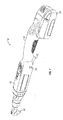
- FIG. 1 one illustrative embodiment of a power tool 10 having a primary switch 12 and a reconfigurable secondary switch 20 is shown.
- the primary switch 12 is coupled to a housing 14 of the power tool 10 and is configured to control a supply of energy to a motor 16 supported in the housing 14.
- the primary switch 12 is embodied as a trigger 12 positioned near a handle portion of the housing 14 (the handle portion being adapted to be gripped by a user when operating the power tool 10).
- the primary switch 12 may be embodied as any other suitable type of user input device and/or may be positioned in any other suitable location on the housing 14.
- the primary switch 12 When a user activates the primary switch 12 (e.g., depresses the trigger 12), the primary switch 12 connects the motor 16 to an energy source 18 coupled to the power tool 10 to supply energy to the motor 16.
- the supply of energy to the motor 16 will cause rotation of a rotor of the motor 16, thereby driving an output 30 of the power tool 10 (for instance, via a drive train included in the power tool 10).
- the motor 16 being supplied with energy will result in rotation of an output shaft 30 of the power tool 10.
- the energy source 18 may be illustratively embodied as a rechargeable battery 18 coupled to the power tool 10 (as shown in FIG.
- an electrical cord e.g., electrically coupled to AC mains power
- a hose or other conduit for pressurized air e.g., fluidly coupled to an air compressor
- the power tool 10 is illustratively shown as a right angle wrench in FIG. 1 , it is contemplated that the concepts of the present disclosure may be incorporated into any type of power tool.
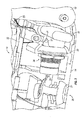
- FIGS. 2 and 3 illustrate partial cross-sectional views of a central portion of the power tool 10, showing the reconfigurable secondary switch 20 of the power tool 10.
- the housing 14 of the power tool 10 includes two mounting positions 24, 26 for the secondary switch 20 (the two mounting positions 24, 26 being spaced apart from one another).
- FIG. 2 shows the secondary switch 20 coupled to the housing 14 in the mounting position 24 that is near the primary switch 12
- FIG. 3 shows the secondary switch 20 coupled to the housing 14 in the mounting position 26 that is away from the primary switch 12.
- the secondary switch 20 is mounted entirely within the housing 14 when in the mounting position 24 (no portion of the secondary switch 20 is exposed to the exterior of the housing 14), while the secondary switch 20 is mounted only partially within the housing 14 when in the mounting position 26 (such that an activation surface 21 of the secondary switch 20 is exposed to an exterior of the housing 14).
- the activation surface 21 of the secondary switch 20 may protrude through an aperture formed in the housing 14 (which aperture may be partially or wholly sealed by a blanking plate 27 when the secondary switch 20 is instead in the mounting position 24, as shown in FIG. 2 ).
- the secondary switch 20 may be illustratively embodied as any type of user input device.
- the secondary switch 20 is embodied as a momentary hall switch 20 that outputs an electrical signal when the activation surface 21 of the secondary switch 20 is physically depressed.
- the secondary switch 20 is electrically coupled to an electronic controller 32 of the power tool 10 via a number of wires 25 that carry electrical signals representing the state of the secondary switch 20 to the electronic controller 32.
- the primary switch 12 is electrically coupled to the electronic controller 32 of the power tool 10 via a number of wires 25 that carry electrical signals representing the state of the primary switch 12 to the electronic controller 32.
- the power tool 10 also includes a shuttle 22 disposed near the mounting position 24 of the secondary switch 20.
- a shuttle 22 disposed near the mounting position 24 of the secondary switch 20.
- one end of the shuttle 22 extends through an aperture formed in a side wall of the housing 14.
- the opposite end of the shuttle 22 extends through another aperture formed in an opposing side wall of the housing 14 (not shown).
- the shuttle 22 is configured to slide from side-to-side such that portions of the shuttle 22 pass through these apertures formed in the side walls of the housing 14.
- the shuttle 22 includes a cam surfaces 28 that engage the activation surface 21 of the secondary switch 20 as the shuttle 22 slides to one side or the other (when the secondary switch 20 is coupled to the housing 14 in the mounting position 24).
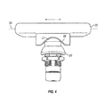
- FIG. 4 illustrates an isolated, top view of the shuttle 22 and the secondary switch 20 (in the mounting position 24), showing the side-to-side motion of the shuttle 22 along a shuttle axis 34.
- the cam surface 28 of the shuttle 22 will depress the activation surface 21 of the secondary switch 20 in a direction substantially perpendicular to that of the shuttle axis 34.
- the shuttle 22 may be locked in place to prevent side-to-side movement of the shuttle 22.
- the blanking plate 27 (after being removed from the aperture formed in the bottom surface of the housing 14) may be positioned in the mounting position 24 (formerly occupied by the secondary switch 20).
- the blanking plate 27 may be sized such that, when positioned in the mounting position 24, the blanking plate 27 abuts the cam surface 28 of the shuttle 22 to resist side-to-side movement of the shuttle 22.
- the power tool 10 may include a pair of complementary shuttles 52, 54, as shown in FIGS. 5-6B (rather than the unitary shuttle 22 of FIGS. 1-4 ).
- the shuttle 52 may extend through an aperture formed in one side wall of the housing 14, while the shuttle 54 may extend through another aperture formed in an opposing side wall of the housing 14.
- the shuttles 52, 54 may each slide (independently) from side-to-side such that portions of the shuttles 52, 54 pass through these respective apertures formed in the side walls of the housing 14.
- the shuttle 52 includes a cam surface 56 that engages the activation surface 21 of the secondary switch 20 as the shuttle 52 slide toward the secondary switch 20 (when the secondary switch 20 is coupled to the housing 14 in the mounting position 24).
- the shuttle 54 includes a cam surface 58 that engages the activation surface 21 of the secondary switch 20 as the shuttle 52 slide toward the secondary switch 20 (when the secondary switch 20 is coupled to the housing 14 in the mounting position 24).
- the corresponding cam surface 56, 58 will depress the activation surface 21 of the secondary switch 20.
- the cam surfaces 56, 58 may be shaped complementary to one another, such that movement of the shuttle 52 toward the secondary switch 20 does not cause the shuttle 54 to extend further out of the housing 14, and vice versa.
- the shuttles 52, 54 may be locked in place to prevent side-to-side movement of the shuttles 52, 54.
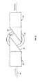
- FIGS. 6A and 6B Two illustrative examples of such locking of the shuttles 52, 54 are shown in FIGS. 6A and 6B .
- a locking tab 61 may be placed between the two shuttles 52, 54 (after the secondary switch 20 has been removed from the mounting position 24).
- the locking tab 61 may be sized such that, when positioned between the shuttles 52, 54, the locking tab 61 abuts the cam surfaces 56, 58 to resist side-to-side movement of the shuttles 52, 54.
- the shuttles 52, 54 each include an interlocking feature such that, when the shuttles 52, 54 are both pressed inwardly from the exterior of the housing 14, the interlocking features of the shuttles 52, 54 are coupled together (thereby preventing movement of either of the shuttles 52, 54 relative to the housing 14). Moreover, in the illustrative embodiment of FIG. 6B , when the shuttles 52, 54 are locked together via their interlocking features, outer surfaces of the shuttles 52, 54 are flush with the exterior surface of the housing 14 (i.e., flush with the apertures in the housing 14 through which the shuttles 52, 54 slide).
- the secondary switch 20 When the secondary switch 20 is coupled to the housing 14 in the mounting position 24 (i.e., near the primary switch 12, as shown in FIG. 2 ), a user holding the power tool 10 can simultaneously operate both the primary switch 12 (directly) and the secondary switch 20 (indirectly, via the shuttle 22 or the shuttles 52, 54) using only one hand. In other words, a user gripping the handle portion of the housing 14 may operate the primary switch 12 and/or the secondary switch 20 (via the shuttle 22 or the shuttles 52, 54) without needing to adjust his or her grip on the power tool 10. In contrast, when the secondary switch 20 is coupled to the housing 14 in the mounting position 26 (i.e., away from the primary switch 12, as shown in FIG.
- a user holding the power tool 10 will not be able to simultaneously operate both the primary switch 12 and the secondary switch 20 using the same hand. Rather, simultaneous operation of both the primary switch 12 and the secondary switch 20 will require the user to activate the primary switch 12 with one hand (e.g., a hand gripping the handle portion of the housing 14) and to activate the secondary switch 20 with his or her other hand (e.g., by depressing the activation surface 21 of the secondary switch 20 that protrudes through the aperture formed in the bottom of the housing 14, as shown in FIG. 3 ).
- the secondary switch 20 may be configured to perform differing functions depending on whether the secondary switch 20 is coupled to the housing 14 in the mounting position 24 or in the mounting position 26.
- the power tool 10 illustratively includes an electronic control system 70.
- the control system 70 generally includes the electronic controller 32, the primary switch 12, the secondary switch 20, and the motor 16.
- the control system 70 may include additional or different electronic and/or electromechanical components (which have not been shown in FIG. 7 for clarity), such as additional user input devices, displays or other output devices, sensors for monitoring various operational conditions of the power tool 10, and the like.
- the controller 32 is supported in the housing 14 of the power tool 10 and is communicatively coupled to the primary switch 12, the secondary switch 20, and the motor 16 (as well as other components) via wires 25.
- the controller 32 may be communicatively coupled to the primary switch 12, the secondary switch 20, the motor 16 and/or other components of the control system 70 via other types of connections (e.g., other wired connections or wireless links).
- the controller 32 is, in essence, a master computer of the power tool 10 responsible for interpreting electrical signals received from various components of the power tool 10 (e.g., the switches 12, 20) and for activating, energizing, or otherwise controlling the operation of electronically-controlled components of the power tool 10 (e.g., the motor 16). To do so, the controller 32 includes a number of electronic components commonly associated with electronic controllers utilized in the control of electromechanical systems. In the illustrative embodiment, the controller 32 of the power tool 10 includes a processor 74, an input/output ("I/O") subsystem 76, and a memory 78. It will be appreciated that the controller 32 may include additional or different components, such as any of those commonly found in a computing device (which are not illustrated in FIG. 7 for clarity). Additionally, in some embodiments, one or more of the illustrative components of the controller 32 may be incorporated in, or otherwise form a portion of, another component of the controller 32 (e.g., as with a microcontroller).
- the processor 74 of the controller 32 may be embodied as any type of processor(s) capable of performing the functions described herein.
- the processor 74 may be embodied as one or more single or multi-core processors, digital signal processors, microcontrollers, or other processors or processing/controlling circuits.
- the memory 78 may be embodied as any type of volatile or non-volatile memory or data storage device capable of performing the functions described herein.
- the memory 78 stores various data and software used during operation of the controller 32, such as operating systems, applications, programs, libraries, and drivers.
- the memory 78 may store instructions in the form of a software routine (or routines) which, when executed by the processor 74, allows the controller 32 to control operation of the power tool 10.
- the memory 78 is communicatively coupled to the processor 74 via the I/O subsystem 76, which may be embodied as circuitry and/or components to facilitate I/O operations of the controller 32.
- the I/O subsystem 76 may be embodied as, or otherwise include, memory controller hubs, I/O control hubs, firmware devices, communication links (e.g., point-to-point links, bus links, wires, cables, light guides, printed circuit board traces, etc.), and/or other components and subsystems to facilitate the I/O operations.
- the I/O subsystem 76 includes an analog-to-digital (“A/D”) converter, or the like, that converts analog signals from the switches 12, 20 of the power tool 10 into digital signals for use by the processor 74. It should be appreciated that, if any one or more of the switches 12, 20 associated with the power tool 10 generate a digital output signal, the A/D converter may be bypassed. Similarly, in the illustrative embodiment, the I/O subsystem 76 includes a digital-to-analog (“D/A”) converter, or the like, that converts digital signals from the processor 74 into analog signals to control operation of the motor 16 of the power tool 10. It should also be appreciated that, if the motor 16 operates using a digital input signal, the D/A converter may be bypassed.
- A/D analog-to-digital
- the primary switch 12 is operable to control the supply of energy to the motor 16.
- energy being supplied to the motor 16 causes rotation of the rotor of the motor 16 (and, hence, rotation of the output shaft 30 of the power tool 10).
- the software executed by the controller 32 may cause the controller 32 to interpret electrical signals received from the primary switch 12 (via the I/O subsystem 76) as indicating whether the motor 16 should be supplied with energy (and, in some embodiments, how much energy).
- the controller 32 may respond to electrical signals received from the primary switch 12 by causing appropriate control signals to be sent (via the I/O subsystem 76) to cause the motor 16 to be supplied with energy.
- the secondary switch 20 when the secondary switch 20 is coupled to the housing 14 in the mounting position 24 (i.e., near the primary switch 12, as shown in FIG. 2 ), the secondary switch 20 may be operable to control a direction of operation of the motor 16.
- the software executed by the controller 32 may cause the controller 32 to interpret electrical signals received from the secondary switch 20 as indicating that a user desires to change the direction of operation of the motor 16 (e.g., from forward to reverse, or vice versa).
- the software may cause the controller 32 to respond to electrical signals received from the secondary switch 20 (when in the mounting position 24) by sending appropriate control signals to the motor 16 (or to another component) to cause the motor 16 to change its direction of operation.
- the controller 32 may execute a particular set of software instructions when the secondary switch 20 is coupled to the housing 14 in the mounting position 24 that cause the controller 32 to perform the operations just described.
- the secondary switch 20 when the secondary switch 20 is coupled to the housing 14 in the mounting position 26 (i.e., away from the primary switch 12, as shown in FIG. 2 ), the secondary switch 20 may be operable to control the supply of energy to the motor 16 (in conjunction with the primary switch 12). In this manner, a two-handed operation by the user may be enforced when the secondary switch 20 is in the mounting position 26.
- the software executed by the controller 32 may cause the controller 32 to send control signals that cause the motor 16 to be supplied with energy only when the controller 32 simultaneously receives electrical signals indicating operation of both the primary switch 12 and the secondary switch 20.
- the software executed by the controller 32 may require both the primary switch 12 and the secondary switch 20 to be simultaneously operated for energy to be supplied to the motor 16.
- This change in the functionality of the secondary switch 20 i.e., performing one function when in the mounting position 24 and another function when in the mounting position 26
- the controller 32 may execute another particular set of software instructions when the secondary switch 20 is coupled to the housing 14 in the mounting position 26 (different than the set of software instructions executed by the controller 32 when the secondary switch 20 is coupled to the housing 14 in the mounting position 24) to cause the controller 32 to perform the operations just described.
- either the primary switch 12 or the secondary switch 20 may be operable to control a direction of operation of the motor 16.
- the software executed by the controller 32 may be configured to cause the controller 32 to interpret electrical signals received from the primary switch 12 that are indicative of the primary switch 12 being briefly depressed and then released as representing that a user desires to change the direction of operation of the motor 16.
- the software executed by the controller 32 may be configured to cause the controller 32 to interpret electrical signals received from the secondary switch 20 that are indicative of the secondary switch 20 being briefly depressed and then released as representing that a user desires to change the direction of operation of the motor 16.
- the software executed by the controller 32 may be configured to cause the controller 32 to interpret simultaneous electrical signals received from either the primary switch 12 and the secondary switch 20 that are indicative of the switches 12, 20 being depressed for longer periods of time as representing that the user desires that energy be supplied to the motor 16. It will be appreciated those of skill in the art that many other control schemes are possible, in addition to the illustrative control schemes described above, by simply reconfiguring the software executed by the controller 32 of the power tool 10.
- FIG. 8 one illustrative embodiment of a method 80 of reconfiguring the power tool 10 of FIGS. 1-7 is shown as a simplified flow diagram.
- the method 80 is illustrated in FIG. 8 as a number of blocks 82-86, which might each be performed by a manufacturer, distributor, and/or end user of the power tool 10, by way of example.
- the block 86 may be optionally performed in some embodiments of the method 80 (and, thus, is shown in dashed lines in FIG. 8 ).
- the method 80 is illustrated in FIG. 8 and described below as involving repositioning of the secondary switch 20 from the mounting position 24 to the mounting position 26 (i.e., to reconfigure the power tool 10 from allowing one-handed operation to requiring two-handed operation).
- the method 80 begins with block 82 in which the secondary switch 20 is removed from the mounting position 24, in which the secondary switch 20 is coupled to the housing 14 near the primary switch 12 (e.g., as shown in FIG. 2 ).
- block 82 may involve opening the housing 14 to allow the secondary switch 20 to be removed from the mounting position 24.
- block 82 may involve locking the shuttle 22 (or, alternatively, the shuttles 52, 54) in place relative to the housing 14 after removing the secondary switch 20 from the mounting position 24. Locking of the shuttle 22 (or the shuttles 52, 54) relative to the housing 14 might be accomplished using any of the illustrative mechanisms described above. (It is also contemplated that, in some embodiments, locking of the shuttle 22 may be performed during or after block 84.)
- block 84 the secondary switch 20 is installed in the mounting position 26, in which the secondary switch 20 is coupled to the housing 14 away from the primary switch 12 (e.g., as shown in FIG. 3 ).
- block 82 may involve removing the blanking plate 27 from the housing 14 to open an aperture in the bottom surface of the housing 14, thereby allowing the activation surface 21 of the secondary switch 20 to be exposed to an exterior of the housing 14.
- block 84 may also involve reassembling or closing the housing 14.
- the method 80 may also involve block 86, in which the software executed by the controller 32 is reconfigured to modify the function(s) performed by the secondary switch 20. For instance, different sets of software instructions might be executed by the controller 32 (e.g., depending on whether the secondary switch 20 was in mounting position 24 or in the mounting position 26) to cause the controller 32 to perform different actions in response to electrical signals received from the secondary switch 20. As described above, the software executed by the controller 32 may cause the controller 32 to interpret electrical signals received from the secondary switch 20 as indicating that the direction of operation of the motor 16 should be changed when the secondary switch 20 is in the mounting position 24. In such cases, block 86 may involve reconfiguring the software of the controller 32 such that the controller 32 interprets electrical signals received from the secondary switch 20 as indicating that energy should be supplied to the motor 16 (when received in conjunction with electrical signals from the primary switch 12).
- the secondary switch 20 is able to remain connected to the same input of the controller 32.
- changing the function performed by the secondary switch 20 in response to the secondary switch 20 moving between the mounting positions 24, 26) does not require re-wiring of the secondary switch 20 to a different input of the controller 32.
- modifying the function(s) performed by the secondary switch 20 may simply involve reconfiguring the software executed by the controller 32.
- the controls of the power tool 10 may be easily reconfigured by a manufacturer, distributor, and/or end user of the power tool 10.
Landscapes
- Engineering & Computer Science (AREA)
- Mechanical Engineering (AREA)
- Portable Power Tools In General (AREA)
- Switch Cases, Indication, And Locking (AREA)
Abstract
Description
- The present disclosure relates, generally, to power tools, and, more particularly, power tools having a reconfigurable secondary switch.
- In addition to a primary switch that controls the supply of energy to a motor, many power tools have an secondary switch that controls a direction of operation of the motor (e.g., forward or reverse operation). This secondary switch is often accessible by a user of the power tool with the same hand used to activate the primary switch, allowing one-handed operation of the power tool. If one-handed operation of a power tool is deemed potentially hazardous to a user, an additional switch is typically added to the tool to require two-handed operation. Such power tools often require the user to depress both the primary switch and the additional switch, which is placed in a position on the power tool such that the same hand of the user cannot depress both the primary switch and the additional switch at the same time. This configuration ensures that both of the user's hands are away from the output of the power tool, reducing the potential for injury.
- According to one aspect, a power tool may comprise a housing supporting a motor, a primary switch coupled to the housing, and an secondary switch. The primary switch may be configured to control a supply of energy to the motor. The secondary switch may be reconfigurable between a first position near the primary switch and a second position spaced apart from the first position. When the secondary switch is coupled to the housing in the first position, the primary switch and the secondary switch may be configured such that a user holding the power tool with only one hand can operate both the primary switch and the secondary switch using the one hand. When the secondary switch is coupled to the housing in the second position, the primary switch and the secondary switch may be configured to require the user of the power tool to simultaneously operate the primary switch and the secondary switch using two hands.
- In some embodiments, when the secondary switch is coupled to the housing in the first position, the secondary switch may be configured to control a direction of operation of the motor. In some embodiments, when the secondary switch is coupled to the housing in the second position, the secondary switch may be configured to control the supply of energy to the motor in conjunction with the primary switch, such that both the primary switch and the secondary switch must be simultaneously operated for energy to be supplied to the motor. In such embodiments, the secondary switch may further be configured to control the direction of the operation of the motor when the secondary switch is coupled to the housing in the second position. In other embodiments, the primary switch may be further configured to control the direction of operation of the motor when the secondary switch is coupled to the housing in the second position.
- In some embodiments, when coupled to the housing in the second position, the secondary switch may be mounted partially within the housing such that an activation surface of the secondary switch is exposed to an exterior of the housing. In some embodiments, when coupled to the housing in the first position, the secondary switch may be mounted entirely within the housing. Further, the power tool may comprise a first shuttle extending through a first aperture formed in the housing. The first shuttle may include a first cam surface configured to activate the secondary switch when the secondary switch is coupled to the housing in the first position and the first shuttle slides through the first aperture. In some embodiments, the first shuttle may be configured to be locked to prevent movement of the first shuttle relative to the housing when the secondary switch is coupled to the housing in the second position.
- In some embodiments, the power tool may further comprise a second shuttle extending through a second aperture formed in the housing. The first and second apertures may be formed in opposing sides of the housing. The second shuttle may include a second cam surface configured to activate the secondary switch when the secondary switch is coupled to the housing in the first position and the second shuttle slides through the second aperture. In some embodiments, the first and second shuttles may each include an interlocking feature allowing the first and second shuttles to be locked together to prevent movement of the first and second shuttles relative to the housing when the secondary switch is coupled to the housing in the second position. In some embodiments, the first shuttle may be flush with the first aperture and the second shuttle may be flush with the second aperture, when the first and second shuttles are locked together.
- According to another aspect, a power tool may comprise a housing supporting a motor, a primary switch coupled to the housing, and an secondary switch that may be reconfigurable between a first position near the primary switch and a second position spaced apart from the first position. When the secondary switch is coupled to the housing in the first position, the secondary switch may be configured to perform a first function. When the secondary switch is coupled to the housing in the second position, the secondary switch may be configured to perform a second function.
- In some embodiments, the first function may comprise controlling a direction of operation of the motor. In some embodiments, the second function may comprise controlling the supply of energy to the motor in conjunction with the primary switch, such that both the primary switch and the secondary switch must be simultaneously operated for energy to be supplied to the motor.
- In some embodiments, when coupled to the housing in the second position, the secondary switch may be further configured to perform the first function in addition to the second function. In some embodiments, the primary switch may be configured to perform the first function in addition to controlling the supply of energy to the motor.
- In some embodiments, the power tool may further comprise an electronic controller positioned in the housing. The primary switch may be communicatively coupled to a first input of the electronic controller. The secondary switch may be communicatively coupled to a second input of the electronic controller, both when the secondary switch is coupled to the housing in the first position and when the secondary switch is coupled to the housing in the second position. When the secondary switch is coupled to the housing in the first position, the electronic controller may be configured to execute a first set of instructions that implement the first function. When the secondary switch is coupled to the housing in the second position, the electronic controller may be configured to execute a second set of instructions that implement the second function.
- According to yet another aspect, a method of reconfiguring a power tool comprising a housing, a primary switch, and an secondary switch may comprise removing the secondary switch from a first position in which the secondary switch is coupled to the housing near the primary switch such that the primary and secondary switches allow one-handed operation of the power tool and installing the secondary switch in a second position in which the secondary switch is coupled to the housing away from the primary switch such that the primary and secondary switches require two-handed operation of the power tool.
- In some embodiments, the method of reconfiguring the power tool may further comprise reconfiguring an electronic controller of the power tool such that the secondary switch, when coupled to the housing in the second position, performs a different function than when the secondary switch was coupled to the housing in the first position.
- The invention will now be further described by way of example with reference to the accompanying drawings, in which:
-
FIG. 1 is a perspective view of one illustrative embodiment of a power tool having a primary switch and a reconfigurable secondary switch; -
FIG. 2 is a partial cross-sectional view of a central portion of the power tool ofFIG. 1 , showing the secondary switch positioned near the primary switch; -
FIG. 3 is a partial cross-sectional view of a central portion of the power tool ofFIG. 1 , showing the secondary switch positioned away from the primary switch; -
FIG. 4 is an isolated, top view of the secondary switch and a shuttle of the power tool ofFIG. 1 ; -
FIG. 5 is a simplified diagram showing one illustrative embodiment of two shuttles that may be used together with the secondary switch of the power tool ofFIG. 1 ; -
FIG. 6A is a simplified diagram of the two shuttles ofFIG. 5 being locked to prevent movement relative to the housing; -
FIG. 6B is another simplified diagram of the two shuttles ofFIG. 5 being locked to prevent movement relative to the housing; -
FIG. 7 is a simplified block diagram of an electronic control system of the power tool ofFIG. 1 ; and -
FIG. 8 is a simplified flow diagram of one illustrative embodiment of a method of reconfiguring the power tool ofFIG. 1 . - Referring now to
FIG. 1 , one illustrative embodiment of apower tool 10 having aprimary switch 12 and a reconfigurablesecondary switch 20 is shown. Theprimary switch 12 is coupled to ahousing 14 of thepower tool 10 and is configured to control a supply of energy to amotor 16 supported in thehousing 14. In the illustrative embodiment shown inFIG. 1 , theprimary switch 12 is embodied as atrigger 12 positioned near a handle portion of the housing 14 (the handle portion being adapted to be gripped by a user when operating the power tool 10). It will be appreciated that, in other embodiments, theprimary switch 12 may be embodied as any other suitable type of user input device and/or may be positioned in any other suitable location on thehousing 14. - When a user activates the primary switch 12 (e.g., depresses the trigger 12), the
primary switch 12 connects themotor 16 to anenergy source 18 coupled to thepower tool 10 to supply energy to themotor 16. The supply of energy to themotor 16 will cause rotation of a rotor of themotor 16, thereby driving anoutput 30 of the power tool 10 (for instance, via a drive train included in the power tool 10). For instance, in the illustrative embodiment shown inFIG. 1 , themotor 16 being supplied with energy will result in rotation of anoutput shaft 30 of thepower tool 10. Theenergy source 18 may be illustratively embodied as arechargeable battery 18 coupled to the power tool 10 (as shown inFIG. 1 ), an electrical cord (e.g., electrically coupled to AC mains power), or a hose or other conduit for pressurized air (e.g., fluidly coupled to an air compressor). Although thepower tool 10 is illustratively shown as a right angle wrench inFIG. 1 , it is contemplated that the concepts of the present disclosure may be incorporated into any type of power tool. -
FIGS. 2 and3 illustrate partial cross-sectional views of a central portion of thepower tool 10, showing the reconfigurablesecondary switch 20 of thepower tool 10. As can been seen inFIGS. 2 and3 , thehousing 14 of thepower tool 10 includes twomounting positions mounting positions FIG. 2 shows thesecondary switch 20 coupled to thehousing 14 in themounting position 24 that is near theprimary switch 12, whileFIG. 3 shows thesecondary switch 20 coupled to thehousing 14 in themounting position 26 that is away from theprimary switch 12. In the illustrative embodiment, thesecondary switch 20 is mounted entirely within thehousing 14 when in the mounting position 24 (no portion of thesecondary switch 20 is exposed to the exterior of the housing 14), while thesecondary switch 20 is mounted only partially within thehousing 14 when in the mounting position 26 (such that anactivation surface 21 of thesecondary switch 20 is exposed to an exterior of the housing 14). When in themounting position 26, theactivation surface 21 of thesecondary switch 20 may protrude through an aperture formed in the housing 14 (which aperture may be partially or wholly sealed by ablanking plate 27 when thesecondary switch 20 is instead in themounting position 24, as shown inFIG. 2 ). - The
secondary switch 20 may be illustratively embodied as any type of user input device. In the illustrative embodiment shown inFIGS. 2 and3 , thesecondary switch 20 is embodied as amomentary hall switch 20 that outputs an electrical signal when theactivation surface 21 of thesecondary switch 20 is physically depressed. Thesecondary switch 20 is electrically coupled to anelectronic controller 32 of thepower tool 10 via a number ofwires 25 that carry electrical signals representing the state of thesecondary switch 20 to theelectronic controller 32. Similarly, theprimary switch 12 is electrically coupled to theelectronic controller 32 of thepower tool 10 via a number ofwires 25 that carry electrical signals representing the state of theprimary switch 12 to theelectronic controller 32. - In the illustrative embodiment, the
power tool 10 also includes ashuttle 22 disposed near the mountingposition 24 of thesecondary switch 20. As best seen inFIG. 1 , one end of theshuttle 22 extends through an aperture formed in a side wall of thehousing 14. Similarly, the opposite end of theshuttle 22 extends through another aperture formed in an opposing side wall of the housing 14 (not shown). Theshuttle 22 is configured to slide from side-to-side such that portions of theshuttle 22 pass through these apertures formed in the side walls of thehousing 14. Theshuttle 22 includes a cam surfaces 28 that engage theactivation surface 21 of thesecondary switch 20 as theshuttle 22 slides to one side or the other (when thesecondary switch 20 is coupled to thehousing 14 in the mounting position 24). -
FIG. 4 illustrates an isolated, top view of theshuttle 22 and the secondary switch 20 (in the mounting position 24), showing the side-to-side motion of theshuttle 22 along ashuttle axis 34. As will be appreciated fromFIG. 4 , as theshuttle 22 slides along the shuttle axis 34 (in either direction), thecam surface 28 of theshuttle 22 will depress theactivation surface 21 of thesecondary switch 20 in a direction substantially perpendicular to that of theshuttle axis 34. In some embodiments, when thesecondary switch 20 is coupled to thehousing 14 in the mounting position 26 (as shown inFIG. 3 ), theshuttle 22 may be locked in place to prevent side-to-side movement of theshuttle 22. For instance, in one illustrative embodiment, the blanking plate 27 (after being removed from the aperture formed in the bottom surface of the housing 14) may be positioned in the mounting position 24 (formerly occupied by the secondary switch 20). The blankingplate 27 may be sized such that, when positioned in the mountingposition 24, the blankingplate 27 abuts thecam surface 28 of theshuttle 22 to resist side-to-side movement of theshuttle 22. - In some embodiments, the
power tool 10 may include a pair ofcomplementary shuttles FIGS. 5-6B (rather than theunitary shuttle 22 ofFIGS. 1-4 ). Theshuttle 52 may extend through an aperture formed in one side wall of thehousing 14, while theshuttle 54 may extend through another aperture formed in an opposing side wall of thehousing 14. Theshuttles shuttles housing 14. Theshuttle 52 includes acam surface 56 that engages theactivation surface 21 of thesecondary switch 20 as theshuttle 52 slide toward the secondary switch 20 (when thesecondary switch 20 is coupled to thehousing 14 in the mounting position 24). Similarly, theshuttle 54 includes acam surface 58 that engages theactivation surface 21 of thesecondary switch 20 as theshuttle 52 slide toward the secondary switch 20 (when thesecondary switch 20 is coupled to thehousing 14 in the mounting position 24). As will be appreciated fromFIG. 5 , as either of theshuttles cam surface activation surface 21 of thesecondary switch 20. Furthermore, the cam surfaces 56, 58 may be shaped complementary to one another, such that movement of theshuttle 52 toward thesecondary switch 20 does not cause theshuttle 54 to extend further out of thehousing 14, and vice versa. - In some embodiments, when the
secondary switch 20 is coupled to thehousing 14 in the mounting position 26 (as shown inFIG. 3 ), theshuttles shuttles shuttles FIGS. 6A and 6B . In the illustrative embodiment ofFIG. 6A , alocking tab 61 may be placed between the twoshuttles 52, 54 (after thesecondary switch 20 has been removed from the mounting position 24). Thelocking tab 61 may be sized such that, when positioned between theshuttles locking tab 61 abuts the cam surfaces 56, 58 to resist side-to-side movement of theshuttles FIG. 6B , theshuttles shuttles housing 14, the interlocking features of theshuttles shuttles FIG. 6B , when theshuttles shuttles housing 14 through which theshuttles - When the
secondary switch 20 is coupled to thehousing 14 in the mounting position 24 (i.e., near theprimary switch 12, as shown inFIG. 2 ), a user holding thepower tool 10 can simultaneously operate both the primary switch 12 (directly) and the secondary switch 20 (indirectly, via theshuttle 22 or theshuttles 52, 54) using only one hand. In other words, a user gripping the handle portion of thehousing 14 may operate theprimary switch 12 and/or the secondary switch 20 (via theshuttle 22 or theshuttles 52, 54) without needing to adjust his or her grip on thepower tool 10. In contrast, when thesecondary switch 20 is coupled to thehousing 14 in the mounting position 26 (i.e., away from theprimary switch 12, as shown inFIG. 3 ), a user holding thepower tool 10 will not be able to simultaneously operate both theprimary switch 12 and thesecondary switch 20 using the same hand. Rather, simultaneous operation of both theprimary switch 12 and thesecondary switch 20 will require the user to activate theprimary switch 12 with one hand (e.g., a hand gripping the handle portion of the housing 14) and to activate thesecondary switch 20 with his or her other hand (e.g., by depressing theactivation surface 21 of thesecondary switch 20 that protrudes through the aperture formed in the bottom of thehousing 14, as shown inFIG. 3 ). As described further below, thesecondary switch 20 may be configured to perform differing functions depending on whether thesecondary switch 20 is coupled to thehousing 14 in the mountingposition 24 or in the mountingposition 26. - Referring now to
FIG. 7 , thepower tool 10 illustratively includes anelectronic control system 70. Thecontrol system 70 generally includes theelectronic controller 32, theprimary switch 12, thesecondary switch 20, and themotor 16. It will be appreciated that, in some embodiments, thecontrol system 70 may include additional or different electronic and/or electromechanical components (which have not been shown inFIG. 7 for clarity), such as additional user input devices, displays or other output devices, sensors for monitoring various operational conditions of thepower tool 10, and the like. In the illustrative embodiment, thecontroller 32 is supported in thehousing 14 of thepower tool 10 and is communicatively coupled to theprimary switch 12, thesecondary switch 20, and the motor 16 (as well as other components) viawires 25. In other embodiments, thecontroller 32 may be communicatively coupled to theprimary switch 12, thesecondary switch 20, themotor 16 and/or other components of thecontrol system 70 via other types of connections (e.g., other wired connections or wireless links). - The
controller 32 is, in essence, a master computer of thepower tool 10 responsible for interpreting electrical signals received from various components of the power tool 10 (e.g., theswitches 12, 20) and for activating, energizing, or otherwise controlling the operation of electronically-controlled components of the power tool 10 (e.g., the motor 16). To do so, thecontroller 32 includes a number of electronic components commonly associated with electronic controllers utilized in the control of electromechanical systems. In the illustrative embodiment, thecontroller 32 of thepower tool 10 includes aprocessor 74, an input/output ("I/O")subsystem 76, and amemory 78. It will be appreciated that thecontroller 32 may include additional or different components, such as any of those commonly found in a computing device (which are not illustrated inFIG. 7 for clarity). Additionally, in some embodiments, one or more of the illustrative components of thecontroller 32 may be incorporated in, or otherwise form a portion of, another component of the controller 32 (e.g., as with a microcontroller). - The
processor 74 of thecontroller 32 may be embodied as any type of processor(s) capable of performing the functions described herein. For example, theprocessor 74 may be embodied as one or more single or multi-core processors, digital signal processors, microcontrollers, or other processors or processing/controlling circuits. Similarly, thememory 78 may be embodied as any type of volatile or non-volatile memory or data storage device capable of performing the functions described herein. Thememory 78 stores various data and software used during operation of thecontroller 32, such as operating systems, applications, programs, libraries, and drivers. For instance, thememory 78 may store instructions in the form of a software routine (or routines) which, when executed by theprocessor 74, allows thecontroller 32 to control operation of thepower tool 10. - The
memory 78 is communicatively coupled to theprocessor 74 via the I/O subsystem 76, which may be embodied as circuitry and/or components to facilitate I/O operations of thecontroller 32. For example, the I/O subsystem 76 may be embodied as, or otherwise include, memory controller hubs, I/O control hubs, firmware devices, communication links (e.g., point-to-point links, bus links, wires, cables, light guides, printed circuit board traces, etc.), and/or other components and subsystems to facilitate the I/O operations. In the illustrative embodiment, the I/O subsystem 76 includes an analog-to-digital ("A/D") converter, or the like, that converts analog signals from theswitches power tool 10 into digital signals for use by theprocessor 74. It should be appreciated that, if any one or more of theswitches power tool 10 generate a digital output signal, the A/D converter may be bypassed. Similarly, in the illustrative embodiment, the I/O subsystem 76 includes a digital-to-analog ("D/A") converter, or the like, that converts digital signals from theprocessor 74 into analog signals to control operation of themotor 16 of thepower tool 10. It should also be appreciated that, if themotor 16 operates using a digital input signal, the D/A converter may be bypassed. - In the illustrative embodiment, the
primary switch 12 is operable to control the supply of energy to themotor 16. As described above, energy being supplied to themotor 16 causes rotation of the rotor of the motor 16 (and, hence, rotation of theoutput shaft 30 of the power tool 10). The software executed by thecontroller 32 may cause thecontroller 32 to interpret electrical signals received from the primary switch 12 (via the I/O subsystem 76) as indicating whether themotor 16 should be supplied with energy (and, in some embodiments, how much energy). As such, thecontroller 32 may respond to electrical signals received from theprimary switch 12 by causing appropriate control signals to be sent (via the I/O subsystem 76) to cause themotor 16 to be supplied with energy. - In some illustrative embodiments, when the
secondary switch 20 is coupled to thehousing 14 in the mounting position 24 (i.e., near theprimary switch 12, as shown inFIG. 2 ), thesecondary switch 20 may be operable to control a direction of operation of themotor 16. In other words, when thesecondary switch 20 is in the mountingposition 24, the software executed by thecontroller 32 may cause thecontroller 32 to interpret electrical signals received from thesecondary switch 20 as indicating that a user desires to change the direction of operation of the motor 16 (e.g., from forward to reverse, or vice versa). As such, the software may cause thecontroller 32 to respond to electrical signals received from the secondary switch 20 (when in the mounting position 24) by sending appropriate control signals to the motor 16 (or to another component) to cause themotor 16 to change its direction of operation. Thecontroller 32 may execute a particular set of software instructions when thesecondary switch 20 is coupled to thehousing 14 in the mountingposition 24 that cause thecontroller 32 to perform the operations just described. - In some illustrative embodiments, when the
secondary switch 20 is coupled to thehousing 14 in the mounting position 26 (i.e., away from theprimary switch 12, as shown inFIG. 2 ), thesecondary switch 20 may be operable to control the supply of energy to the motor 16 (in conjunction with the primary switch 12). In this manner, a two-handed operation by the user may be enforced when thesecondary switch 20 is in the mountingposition 26. For instance, the software executed by thecontroller 32 may cause thecontroller 32 to send control signals that cause themotor 16 to be supplied with energy only when thecontroller 32 simultaneously receives electrical signals indicating operation of both theprimary switch 12 and thesecondary switch 20. In other words, when thesecondary switch 20 is in the mountingposition 26, the software executed by thecontroller 32 may require both theprimary switch 12 and thesecondary switch 20 to be simultaneously operated for energy to be supplied to themotor 16. This change in the functionality of the secondary switch 20 (i.e., performing one function when in the mountingposition 24 and another function when in the mounting position 26) may be achieved by reconfiguring the software executed by thecontroller 32. In other words, thecontroller 32 may execute another particular set of software instructions when thesecondary switch 20 is coupled to thehousing 14 in the mounting position 26 (different than the set of software instructions executed by thecontroller 32 when thesecondary switch 20 is coupled to thehousing 14 in the mounting position 24) to cause thecontroller 32 to perform the operations just described. - Furthermore, when the
secondary switch 20 is coupled to thehousing 14 in the mounting position 26 (i.e., away from theprimary switch 12, as shown inFIG. 2 ), either theprimary switch 12 or the secondary switch 20 (or both) may be operable to control a direction of operation of themotor 16. For instance, in some embodiments, the software executed by thecontroller 32 may be configured to cause thecontroller 32 to interpret electrical signals received from theprimary switch 12 that are indicative of theprimary switch 12 being briefly depressed and then released as representing that a user desires to change the direction of operation of themotor 16. Additionally or alternatively, the software executed by thecontroller 32 may be configured to cause thecontroller 32 to interpret electrical signals received from thesecondary switch 20 that are indicative of thesecondary switch 20 being briefly depressed and then released as representing that a user desires to change the direction of operation of themotor 16. In such a control scheme, the software executed by thecontroller 32 may be configured to cause thecontroller 32 to interpret simultaneous electrical signals received from either theprimary switch 12 and thesecondary switch 20 that are indicative of theswitches motor 16. It will be appreciated those of skill in the art that many other control schemes are possible, in addition to the illustrative control schemes described above, by simply reconfiguring the software executed by thecontroller 32 of thepower tool 10. - Referring now to
FIG. 8 , one illustrative embodiment of amethod 80 of reconfiguring thepower tool 10 ofFIGS. 1-7 is shown as a simplified flow diagram. Themethod 80 is illustrated inFIG. 8 as a number of blocks 82-86, which might each be performed by a manufacturer, distributor, and/or end user of thepower tool 10, by way of example. Theblock 86 may be optionally performed in some embodiments of the method 80 (and, thus, is shown in dashed lines inFIG. 8 ). Themethod 80 is illustrated inFIG. 8 and described below as involving repositioning of thesecondary switch 20 from the mountingposition 24 to the mounting position 26 (i.e., to reconfigure thepower tool 10 from allowing one-handed operation to requiring two-handed operation). It will be appreciated that another embodiment of themethod 80, involving repositioning of thesecondary switch 20 from the mountingposition 26 to the mounting position 24 (i.e., to reconfigure thepower tool 10 from requiring two-handed operation to allowing one-handed operation), might also be performed. - The
method 80 begins withblock 82 in which thesecondary switch 20 is removed from the mountingposition 24, in which thesecondary switch 20 is coupled to thehousing 14 near the primary switch 12 (e.g., as shown inFIG. 2 ). In some embodiments, block 82 may involve opening thehousing 14 to allow thesecondary switch 20 to be removed from the mountingposition 24. Furthermore, in some embodiments, block 82 may involve locking the shuttle 22 (or, alternatively, theshuttles 52, 54) in place relative to thehousing 14 after removing thesecondary switch 20 from the mountingposition 24. Locking of the shuttle 22 (or theshuttles 52, 54) relative to thehousing 14 might be accomplished using any of the illustrative mechanisms described above. (It is also contemplated that, in some embodiments, locking of theshuttle 22 may be performed during or afterblock 84.) - After
block 82, themethod 80 proceeds to block 84, where thesecondary switch 20 is installed in the mountingposition 26, in which thesecondary switch 20 is coupled to thehousing 14 away from the primary switch 12 (e.g., as shown inFIG. 3 ). In some embodiments, block 82 may involve removing the blankingplate 27 from thehousing 14 to open an aperture in the bottom surface of thehousing 14, thereby allowing theactivation surface 21 of thesecondary switch 20 to be exposed to an exterior of thehousing 14. Where thehousing 14 was opened inblock 82, block 84 may also involve reassembling or closing thehousing 14. - In some embodiments, the
method 80 may also involveblock 86, in which the software executed by thecontroller 32 is reconfigured to modify the function(s) performed by thesecondary switch 20. For instance, different sets of software instructions might be executed by the controller 32 (e.g., depending on whether thesecondary switch 20 was in mountingposition 24 or in the mounting position 26) to cause thecontroller 32 to perform different actions in response to electrical signals received from thesecondary switch 20. As described above, the software executed by thecontroller 32 may cause thecontroller 32 to interpret electrical signals received from thesecondary switch 20 as indicating that the direction of operation of themotor 16 should be changed when thesecondary switch 20 is in the mountingposition 24. In such cases, block 86 may involve reconfiguring the software of thecontroller 32 such that thecontroller 32 interprets electrical signals received from thesecondary switch 20 as indicating that energy should be supplied to the motor 16 (when received in conjunction with electrical signals from the primary switch 12). - It will be appreciated from the above discussion that, in the illustrative embodiment, the
secondary switch 20 is able to remain connected to the same input of thecontroller 32. In other words, changing the function performed by the secondary switch 20 (in response to thesecondary switch 20 moving between the mountingpositions 24, 26) does not require re-wiring of thesecondary switch 20 to a different input of thecontroller 32. Rather, modifying the function(s) performed by thesecondary switch 20 may simply involve reconfiguring the software executed by thecontroller 32. As such, the controls of thepower tool 10 may be easily reconfigured by a manufacturer, distributor, and/or end user of thepower tool 10. - While certain illustrative embodiments have been described in detail in the figures and the foregoing description, such an illustration and description is to be considered as exemplary and not restrictive in character, it being understood that only illustrative embodiments have been shown and described. There are a plurality of advantages of the present disclosure arising from the various features of the apparatus, systems, and methods described herein. It will be noted that alternative embodiments of the apparatus, systems, and methods of the present disclosure may not include all of the features described yet still benefit from at least some of the advantages of such features. Those of ordinary skill in the art may readily devise their own implementations of the apparatus, systems, and methods that incorporate one or more of the features of the present disclosure.
Claims (15)
- A power tool comprising:a housing supporting a motor;a primary switch coupled to the housing and configured to control a supply of energy to the motor; andan secondary switch that is reconfigurable between a first position near the primary switch and a second position spaced apart from the first position, wherein (i) when the secondary switch is coupled to the housing in the first position, the primary switch and the secondary switch are configured such that a user holding the power tool with only one hand can operate both the primary switch and the secondary switch using the one hand and (ii) when the secondary switch is coupled to the housing in the second position, the primary switch and the secondary switch are configured to require the user of the power tool to simultaneously operate the primary switch and the secondary switch using two hands.
- The power tool of claim 1, wherein the secondary switch, when coupled to the housing in the first position, is configured to control a direction of operation of the motor.
- The power tool of claim 2, wherein the secondary switch, when coupled to the housing in the second position, is configured to control the supply of energy to the motor in conjunction with the primary switch, such that both the primary switch and the secondary switch must be simultaneously operated for energy to be supplied to the motor.
- The power tool of claim 3, wherein the secondary switch, when coupled to the housing in the second position, is further configured to control the direction of operation of the motor.
- The power tool of claim 3, wherein the primary switch is further configured to control the direction of operation of the motor when the secondary switch is coupled to the housing in the second position.
- The power tool of any preceding claim, wherein the secondary switch, when coupled to the housing in the second position, is mounted partially within the housing such that an activation surface of the secondary switch is exposed to an exterior of the housing.
- The power tool of claim 6, wherein:the secondary switch, when coupled to the housing in the first position, is mounted entirely within the housing; andthe power tool further comprises a first shuttle extending through a first aperture formed in the housing, the first shuttle including a first cam surface configured to activate the secondary switch when the secondary switch is coupled to the housing in the first position and the first shuttle slides through the first aperture.
- The power tool of claim 7, wherein the first shuttle is configured to be locked to prevent movement of the first shuttle relative to the housing when the secondary switch is coupled to the housing in the second position.
- The power tool of claim 8, further comprising a second shuttle extending through a second aperture formed in the housing, the first and second apertures being formed in opposing sides of the housing, the second shuttle including a second cam surface configured to activate the secondary switch when the secondary switch is coupled to the housing in the first position and the second shuttle slides through the second aperture.
- The power tool of claim 9, wherein the first and second shuttles each include an interlocking feature allowing the first and second shuttles to be locked together to prevent movement of the first and second shuttles relative to the housing when the secondary switch is coupled to the housing in the second position.
- The power tool of claim 10, wherein the first shuttle is flush with the first aperture and the second shuttle is flush with the second aperture when the first and second shuttles are locked together.
- The power tool of any preceding claim, further comprising an electronic controller positioned in the housing, wherein (i) the primary switch is communicatively coupled to a first input of the electronic controller and (ii) the secondary switch is communicatively coupled to a second input of the electronic controller, both when the secondary switch is coupled to the housing in the first position and when the secondary switch is coupled to the housing in the second position.
- The power tool of claim 12, wherein the electronic controller is configured to execute a first set of instructions that implement a first function, when the secondary switch is coupled to the housing in the first position, and to execute a second set of instructions that implement a second function different from the first function, when the secondary switch is coupled to the housing in the second position.
- A method of reconfiguring a power tool comprising a housing, a primary switch, and an secondary switch, the method comprising:removing the secondary switch from a first position in which the secondary switch is coupled to the housing near the primary switch such that the primary and secondary switches allow one-handed operation of the power tool; andinstalling the secondary switch in a second position in which the secondary switch is coupled to the housing away from primary switch such that the primary and secondary switches require two-handed operation of the power tool.
- The method of claim 14, further comprising reconfiguring an electronic controller of the power tool such that the secondary switch, when coupled to the housing in the second position, performs a different function than when the secondary switch was coupled to the housing in the first position.
Applications Claiming Priority (1)
| Application Number | Priority Date | Filing Date | Title |
|---|---|---|---|
| US14/184,943 US9701006B2 (en) | 2014-02-20 | 2014-02-20 | Power tools with reconfigurable secondary switch |
Publications (2)
| Publication Number | Publication Date |
|---|---|
| EP2944430A1 true EP2944430A1 (en) | 2015-11-18 |
| EP2944430B1 EP2944430B1 (en) | 2016-09-14 |
Family
ID=52997814
Family Applications (1)
| Application Number | Title | Priority Date | Filing Date |
|---|---|---|---|
| EP15155357.5A Active EP2944430B1 (en) | 2014-02-20 | 2015-02-17 | Power tools with reconfigurable secondary switch |
Country Status (3)
| Country | Link |
|---|---|
| US (1) | US9701006B2 (en) |
| EP (1) | EP2944430B1 (en) |
| CN (1) | CN104868657B (en) |
Families Citing this family (9)
| Publication number | Priority date | Publication date | Assignee | Title |
|---|---|---|---|---|
| US11059156B2 (en) * | 2015-01-28 | 2021-07-13 | Koki Holdings Co., Ltd. | Impact tool |
| US20180215029A1 (en) * | 2017-01-31 | 2018-08-02 | Ingersoll-Rand Company | Quick double trigger configuration change |
| SE1850881A1 (en) * | 2018-07-11 | 2020-01-12 | Husqvarna Ab | Power tool |
| US11412631B2 (en) * | 2020-08-26 | 2022-08-09 | Snap-On Incorporated | PCB with integrated switches |
| US12502760B2 (en) | 2021-02-25 | 2025-12-23 | Black & Decker Inc. | Compact powered wrench |
| US11981017B2 (en) | 2021-05-05 | 2024-05-14 | Snap-On Incorporated | Ratchet with toggle trigger |
| EP4101598A1 (en) | 2021-06-07 | 2022-12-14 | Black & Decker, Inc. | Side handle for power tool |
| US12611761B2 (en) | 2021-11-24 | 2026-04-28 | Milwaukee Electric Tool Corporation | Grinder including enhanced sensing and component detection |
| US12485526B2 (en) | 2023-03-13 | 2025-12-02 | Black & Decker Inc. | Gear case grip accessory for power tool |
Citations (5)
| Publication number | Priority date | Publication date | Assignee | Title |
|---|---|---|---|---|
| WO2005063451A1 (en) * | 2003-12-30 | 2005-07-14 | Robert Bosch Gmbh | Electric tool with dually controllable switch |
| EP2140983A2 (en) * | 2008-07-04 | 2010-01-06 | Makita Corporation | Electric power tool |
| WO2011119153A1 (en) * | 2010-03-24 | 2011-09-29 | Cook Bryan C | Ergonomic hand-held power tool and methods of use |
| WO2012167241A1 (en) * | 2011-06-02 | 2012-12-06 | Black & Decker Inc. | Control system for a fastening power tool |
| US20130186665A1 (en) * | 2012-01-19 | 2013-07-25 | Basso Industry Corp. | Switch mechanism for a pneumatic tool |
Family Cites Families (37)
| Publication number | Priority date | Publication date | Assignee | Title |
|---|---|---|---|---|
| FR1579512A (en) | 1968-02-12 | 1969-08-29 | ||
| GB2390324A (en) * | 2002-06-19 | 2004-01-07 | Black & Decker Inc | Power tool with pivoting handle |
| DE3043264A1 (en) | 1980-11-15 | 1982-07-08 | Robert Bosch Gmbh, 7000 Stuttgart | ELECTRONIC TWO-HANDED LOCK FOR TOOLS |
| DE4024564A1 (en) | 1990-08-02 | 1992-02-06 | Black & Decker Inc | MOTOR-DRIVEN, PORTABLE DEVICE, IN PARTICULAR CHAINSAW, HEDGE TRIMMER O.AE. |
| US5150523A (en) | 1991-07-11 | 1992-09-29 | Ryobi Motor Products Corporation | Deadman switch arrangement for a hedge trimmer |
| WO1994011162A1 (en) | 1992-11-06 | 1994-05-26 | Emerson International Limited | A power tool |
| GB9224660D0 (en) | 1992-11-25 | 1993-01-13 | Black & Decker Inc | Improved switch mechanism |
| DE4311624A1 (en) | 1993-04-08 | 1994-10-13 | Gardena Kress & Kastner Gmbh | Hedge trimmer |
| GB2291744B (en) | 1994-07-26 | 1998-04-22 | Atco Qualcast Ltd | Switch actuating mechanism for electrically powered tools |
| DE19522968A1 (en) | 1995-06-28 | 1997-01-02 | Bosch Gmbh Robert | Hedge trimmer |
| US5793141A (en) * | 1995-06-28 | 1998-08-11 | Milwaukee Electric Tool Corp. | Plug-in modular brush cartridge |
| US5969312A (en) | 1998-06-24 | 1999-10-19 | S-B Power Tool Company | Ambidextrous powers-switch lock-out mechanism |
| US6536536B1 (en) | 1999-04-29 | 2003-03-25 | Stephen F. Gass | Power tools |
| WO2001096064A1 (en) | 2000-06-14 | 2001-12-20 | Wen Products, Inc. | Power tool having a pressure responsive activation |
| US6443676B1 (en) * | 2000-07-11 | 2002-09-03 | Roto Zip Tool Corporation | Automatic locking depth guide for cutting tools and the like |
| US6548776B1 (en) | 2002-04-12 | 2003-04-15 | Jenn Feng Industrial Co., Ltd. | Safety device for on/off switch of an electric tool |
| US7143835B2 (en) | 2003-03-17 | 2006-12-05 | Honda Motor Co., Ltd. | Walk-behind electric working machine |
| EP1504656B1 (en) * | 2003-08-04 | 2006-05-17 | BLACK & DECKER INC. | Actuation mechanism for a power tool |
| GB2404832A (en) | 2003-08-09 | 2005-02-16 | Black & Decker Inc | Safety mechanism for power tool |
| US20060102367A1 (en) * | 2004-02-04 | 2006-05-18 | Etter Mark A | Pneumatically powered rotary tool having linear forward and reverse switch |
| US7210542B2 (en) | 2004-09-23 | 2007-05-01 | Defond Components Limited | Power tool safety device |
| US20060220612A1 (en) * | 2005-03-31 | 2006-10-05 | Feldmann William M | Modular panel for a power tool |
| SE531000C2 (en) | 2005-11-17 | 2008-11-11 | Atlas Copco Tools Ab | System for imparting the various operating characteristics to a battery operated screw tightening tool |
| GB2432334B (en) | 2005-11-21 | 2010-10-06 | Husqvarna Uk Ltd | Power tool |
| US7836968B2 (en) * | 2006-03-24 | 2010-11-23 | The Stanley Works | Power tool with improved start actuator |
| DE202008000921U1 (en) | 2008-01-23 | 2009-05-28 | Wagner, Paul-Heinz | Screwdrivers |
| FR2935106B1 (en) * | 2008-08-22 | 2010-09-17 | Pellenc Sa | PORTABLE ELECTROPORTATIVE TOOL |
| US8276280B2 (en) | 2008-09-16 | 2012-10-02 | Republic Of Korea (Management: Rural Development Administration) | Electromotion trim scissors |
| WO2010115438A1 (en) | 2009-04-08 | 2010-10-14 | Husqvarna Ab | Battery-powered portable tools |
| JP5472683B2 (en) | 2009-05-11 | 2014-04-16 | 日立工機株式会社 | Electric tool |
| CN201439197U (en) | 2009-07-10 | 2010-04-21 | 宁波中港工具有限公司 | Chargeable multifunctional electrical tool |
| DE102010038753A1 (en) | 2010-08-02 | 2012-02-02 | Robert Bosch Gmbh | Anti-vibration handle with train-loaded switch connection |
| DE202013103023U1 (en) * | 2012-07-14 | 2013-10-04 | Hitachi Koki Co., Ltd. | power tool |
| US9197146B2 (en) * | 2012-07-26 | 2015-11-24 | Milwaukee Electric Tool Corporation | Brushless direct-current motor and control for power tool |
| CN203077178U (en) | 2012-12-31 | 2013-07-24 | 浙江博大实业有限公司 | Charging-type electric wrench |
| US20150059531A1 (en) * | 2013-08-29 | 2015-03-05 | Ingersoll-Rand Company | Ratchet Tools |
| US9550281B2 (en) * | 2013-09-17 | 2017-01-24 | Ming-Ta Cheng | Pneumatic tool |
-
2014
- 2014-02-20 US US14/184,943 patent/US9701006B2/en active Active
-
2015
- 2015-02-17 EP EP15155357.5A patent/EP2944430B1/en active Active
- 2015-02-17 CN CN201510086863.XA patent/CN104868657B/en active Active
Patent Citations (5)
| Publication number | Priority date | Publication date | Assignee | Title |
|---|---|---|---|---|
| WO2005063451A1 (en) * | 2003-12-30 | 2005-07-14 | Robert Bosch Gmbh | Electric tool with dually controllable switch |
| EP2140983A2 (en) * | 2008-07-04 | 2010-01-06 | Makita Corporation | Electric power tool |
| WO2011119153A1 (en) * | 2010-03-24 | 2011-09-29 | Cook Bryan C | Ergonomic hand-held power tool and methods of use |
| WO2012167241A1 (en) * | 2011-06-02 | 2012-12-06 | Black & Decker Inc. | Control system for a fastening power tool |
| US20130186665A1 (en) * | 2012-01-19 | 2013-07-25 | Basso Industry Corp. | Switch mechanism for a pneumatic tool |
Also Published As
| Publication number | Publication date |
|---|---|
| US9701006B2 (en) | 2017-07-11 |
| CN104868657B (en) | 2017-08-04 |
| CN104868657A (en) | 2015-08-26 |
| EP2944430B1 (en) | 2016-09-14 |
| US20150231778A1 (en) | 2015-08-20 |
Similar Documents
| Publication | Publication Date | Title |
|---|---|---|
| EP2944430B1 (en) | Power tools with reconfigurable secondary switch | |
| US9589461B1 (en) | Battery powered wall mounted remote control for ceiling fans and lights | |
| US20180215029A1 (en) | Quick double trigger configuration change | |
| EP3302880A1 (en) | Lighting systems for power tools | |
| JP2009190131A (en) | Electric tool | |
| SE519367C2 (en) | Portable tool with interchangeable module fixed with multi-contact for signaling and operation | |
| WO2010026013A1 (en) | User interface device for low voltage switching devices | |
| CN111714207A (en) | Control system of surgical robot and surgical robot | |
| US20160354912A1 (en) | Power Tool User Interfaces | |
| US11529726B2 (en) | Hand-held power tool comprising a communication interface | |
| CN104149075A (en) | Hand tool operating unit | |
| CN106998649A (en) | Garden Tool Gripping Device | |
| CN107407925B (en) | Convertible Smart Power Tools | |
| SE524929C2 (en) | A control system with physically separated modules for controlling one or more manipulators | |
| JP6088464B2 (en) | Amplifier integrated robot controller | |
| US20260079524A1 (en) | Joystick | |
| KR20120027934A (en) | Robot system with robot controller combined with teach pedant | |
| JP2023016568A (en) | Switch operation device | |
| JP5970713B2 (en) | Robot controller | |
| WO2008031708A3 (en) | Safety mechanism for a food processor having two coupling points | |
| JP6090922B2 (en) | Teaching device | |
| EP1439463A2 (en) | A drive controller operator interface | |
| JP7404216B2 (en) | lighting equipment | |
| KR102787783B1 (en) | Teaching apparatus for electrical equipment | |
| JP5708142B2 (en) | Robot controller |
Legal Events
| Date | Code | Title | Description |
|---|---|---|---|
| PUAI | Public reference made under article 153(3) epc to a published international application that has entered the european phase |
Free format text: ORIGINAL CODE: 0009012 |
|
| AK | Designated contracting states |
Kind code of ref document: A1 Designated state(s): AL AT BE BG CH CY CZ DE DK EE ES FI FR GB GR HR HU IE IS IT LI LT LU LV MC MK MT NL NO PL PT RO RS SE SI SK SM TR |
|
| AX | Request for extension of the european patent |
Extension state: BA ME |
|
| 17P | Request for examination filed |
Effective date: 20151125 |
|
| RBV | Designated contracting states (corrected) |
Designated state(s): AL AT BE BG CH CY CZ DE DK EE ES FI FR GB GR HR HU IE IS IT LI LT LU LV MC MK MT NL NO PL PT RO RS SE SI SK SM TR |
|
| GRAP | Despatch of communication of intention to grant a patent |
Free format text: ORIGINAL CODE: EPIDOSNIGR1 |
|
| RIC1 | Information provided on ipc code assigned before grant |
Ipc: B25F 5/02 20060101ALI20160225BHEP Ipc: B25F 5/00 20060101AFI20160225BHEP |
|
| INTG | Intention to grant announced |
Effective date: 20160318 |
|
| GRAS | Grant fee paid |
Free format text: ORIGINAL CODE: EPIDOSNIGR3 |
|
| GRAA | (expected) grant |
Free format text: ORIGINAL CODE: 0009210 |
|
| AK | Designated contracting states |
Kind code of ref document: B1 Designated state(s): AL AT BE BG CH CY CZ DE DK EE ES FI FR GB GR HR HU IE IS IT LI LT LU LV MC MK MT NL NO PL PT RO RS SE SI SK SM TR |
|
| REG | Reference to a national code |
Ref country code: GB Ref legal event code: FG4D |
|
| REG | Reference to a national code |
Ref country code: CH Ref legal event code: EP |
|
| REG | Reference to a national code |
Ref country code: IE Ref legal event code: FG4D |
|
| REG | Reference to a national code |
Ref country code: AT Ref legal event code: REF Ref document number: 828416 Country of ref document: AT Kind code of ref document: T Effective date: 20161015 |
|
| REG | Reference to a national code |
Ref country code: DE Ref legal event code: R096 Ref document number: 602015000312 Country of ref document: DE |
|
| REG | Reference to a national code |
Ref country code: FR Ref legal event code: PLFP Year of fee payment: 3 |
|
| REG | Reference to a national code |
Ref country code: SE Ref legal event code: TRGR |
|
| REG | Reference to a national code |
Ref country code: LT Ref legal event code: MG4D |
|
| REG | Reference to a national code |
Ref country code: NL Ref legal event code: MP Effective date: 20160914 |
|
| PG25 | Lapsed in a contracting state [announced via postgrant information from national office to epo] |
Ref country code: FI Free format text: LAPSE BECAUSE OF FAILURE TO SUBMIT A TRANSLATION OF THE DESCRIPTION OR TO PAY THE FEE WITHIN THE PRESCRIBED TIME-LIMIT Effective date: 20160914 Ref country code: HR Free format text: LAPSE BECAUSE OF FAILURE TO SUBMIT A TRANSLATION OF THE DESCRIPTION OR TO PAY THE FEE WITHIN THE PRESCRIBED TIME-LIMIT Effective date: 20160914 Ref country code: NO Free format text: LAPSE BECAUSE OF FAILURE TO SUBMIT A TRANSLATION OF THE DESCRIPTION OR TO PAY THE FEE WITHIN THE PRESCRIBED TIME-LIMIT Effective date: 20161214 Ref country code: LT Free format text: LAPSE BECAUSE OF FAILURE TO SUBMIT A TRANSLATION OF THE DESCRIPTION OR TO PAY THE FEE WITHIN THE PRESCRIBED TIME-LIMIT Effective date: 20160914 Ref country code: RS Free format text: LAPSE BECAUSE OF FAILURE TO SUBMIT A TRANSLATION OF THE DESCRIPTION OR TO PAY THE FEE WITHIN THE PRESCRIBED TIME-LIMIT Effective date: 20160914 |
|
| REG | Reference to a national code |
Ref country code: AT Ref legal event code: MK05 Ref document number: 828416 Country of ref document: AT Kind code of ref document: T Effective date: 20160914 |
|
| PG25 | Lapsed in a contracting state [announced via postgrant information from national office to epo] |
Ref country code: GR Free format text: LAPSE BECAUSE OF FAILURE TO SUBMIT A TRANSLATION OF THE DESCRIPTION OR TO PAY THE FEE WITHIN THE PRESCRIBED TIME-LIMIT Effective date: 20161215 Ref country code: NL Free format text: LAPSE BECAUSE OF FAILURE TO SUBMIT A TRANSLATION OF THE DESCRIPTION OR TO PAY THE FEE WITHIN THE PRESCRIBED TIME-LIMIT Effective date: 20160914 Ref country code: LV Free format text: LAPSE BECAUSE OF FAILURE TO SUBMIT A TRANSLATION OF THE DESCRIPTION OR TO PAY THE FEE WITHIN THE PRESCRIBED TIME-LIMIT Effective date: 20160914 |
|
| PG25 | Lapsed in a contracting state [announced via postgrant information from national office to epo] |
Ref country code: EE Free format text: LAPSE BECAUSE OF FAILURE TO SUBMIT A TRANSLATION OF THE DESCRIPTION OR TO PAY THE FEE WITHIN THE PRESCRIBED TIME-LIMIT Effective date: 20160914 Ref country code: RO Free format text: LAPSE BECAUSE OF FAILURE TO SUBMIT A TRANSLATION OF THE DESCRIPTION OR TO PAY THE FEE WITHIN THE PRESCRIBED TIME-LIMIT Effective date: 20160914 |
|
| PG25 | Lapsed in a contracting state [announced via postgrant information from national office to epo] |
Ref country code: BG Free format text: LAPSE BECAUSE OF FAILURE TO SUBMIT A TRANSLATION OF THE DESCRIPTION OR TO PAY THE FEE WITHIN THE PRESCRIBED TIME-LIMIT Effective date: 20161214 Ref country code: CZ Free format text: LAPSE BECAUSE OF FAILURE TO SUBMIT A TRANSLATION OF THE DESCRIPTION OR TO PAY THE FEE WITHIN THE PRESCRIBED TIME-LIMIT Effective date: 20160914 Ref country code: IS Free format text: LAPSE BECAUSE OF FAILURE TO SUBMIT A TRANSLATION OF THE DESCRIPTION OR TO PAY THE FEE WITHIN THE PRESCRIBED TIME-LIMIT Effective date: 20170114 Ref country code: BE Free format text: LAPSE BECAUSE OF FAILURE TO SUBMIT A TRANSLATION OF THE DESCRIPTION OR TO PAY THE FEE WITHIN THE PRESCRIBED TIME-LIMIT Effective date: 20160914 Ref country code: PL Free format text: LAPSE BECAUSE OF FAILURE TO SUBMIT A TRANSLATION OF THE DESCRIPTION OR TO PAY THE FEE WITHIN THE PRESCRIBED TIME-LIMIT Effective date: 20160914 Ref country code: SM Free format text: LAPSE BECAUSE OF FAILURE TO SUBMIT A TRANSLATION OF THE DESCRIPTION OR TO PAY THE FEE WITHIN THE PRESCRIBED TIME-LIMIT Effective date: 20160914 Ref country code: PT Free format text: LAPSE BECAUSE OF FAILURE TO SUBMIT A TRANSLATION OF THE DESCRIPTION OR TO PAY THE FEE WITHIN THE PRESCRIBED TIME-LIMIT Effective date: 20170116 Ref country code: SK Free format text: LAPSE BECAUSE OF FAILURE TO SUBMIT A TRANSLATION OF THE DESCRIPTION OR TO PAY THE FEE WITHIN THE PRESCRIBED TIME-LIMIT Effective date: 20160914 Ref country code: AT Free format text: LAPSE BECAUSE OF FAILURE TO SUBMIT A TRANSLATION OF THE DESCRIPTION OR TO PAY THE FEE WITHIN THE PRESCRIBED TIME-LIMIT Effective date: 20160914 Ref country code: ES Free format text: LAPSE BECAUSE OF FAILURE TO SUBMIT A TRANSLATION OF THE DESCRIPTION OR TO PAY THE FEE WITHIN THE PRESCRIBED TIME-LIMIT Effective date: 20160914 |
|
| REG | Reference to a national code |
Ref country code: DE Ref legal event code: R097 Ref document number: 602015000312 Country of ref document: DE |
|
| PLBE | No opposition filed within time limit |
Free format text: ORIGINAL CODE: 0009261 |
|
| STAA | Information on the status of an ep patent application or granted ep patent |
Free format text: STATUS: NO OPPOSITION FILED WITHIN TIME LIMIT |
|
| PG25 | Lapsed in a contracting state [announced via postgrant information from national office to epo] |
Ref country code: DK Free format text: LAPSE BECAUSE OF FAILURE TO SUBMIT A TRANSLATION OF THE DESCRIPTION OR TO PAY THE FEE WITHIN THE PRESCRIBED TIME-LIMIT Effective date: 20160914 |
|
| 26N | No opposition filed |
Effective date: 20170615 |
|
| PG25 | Lapsed in a contracting state [announced via postgrant information from national office to epo] |
Ref country code: MC Free format text: LAPSE BECAUSE OF FAILURE TO SUBMIT A TRANSLATION OF THE DESCRIPTION OR TO PAY THE FEE WITHIN THE PRESCRIBED TIME-LIMIT Effective date: 20160914 |
|
| REG | Reference to a national code |
Ref country code: IE Ref legal event code: MM4A |
|
| PG25 | Lapsed in a contracting state [announced via postgrant information from national office to epo] |
Ref country code: SI Free format text: LAPSE BECAUSE OF FAILURE TO SUBMIT A TRANSLATION OF THE DESCRIPTION OR TO PAY THE FEE WITHIN THE PRESCRIBED TIME-LIMIT Effective date: 20160914 |
|
| PG25 | Lapsed in a contracting state [announced via postgrant information from national office to epo] |
Ref country code: LU Free format text: LAPSE BECAUSE OF NON-PAYMENT OF DUE FEES Effective date: 20170217 |
|
| REG | Reference to a national code |
Ref country code: FR Ref legal event code: PLFP Year of fee payment: 4 |
|
| PG25 | Lapsed in a contracting state [announced via postgrant information from national office to epo] |
Ref country code: IE Free format text: LAPSE BECAUSE OF NON-PAYMENT OF DUE FEES Effective date: 20170217 |
|
| REG | Reference to a national code |
Ref country code: CH Ref legal event code: PL |
|
| PG25 | Lapsed in a contracting state [announced via postgrant information from national office to epo] |
Ref country code: MT Free format text: LAPSE BECAUSE OF NON-PAYMENT OF DUE FEES Effective date: 20170217 |
|
| PG25 | Lapsed in a contracting state [announced via postgrant information from national office to epo] |
Ref country code: AL Free format text: LAPSE BECAUSE OF FAILURE TO SUBMIT A TRANSLATION OF THE DESCRIPTION OR TO PAY THE FEE WITHIN THE PRESCRIBED TIME-LIMIT Effective date: 20160914 |
|
| PG25 | Lapsed in a contracting state [announced via postgrant information from national office to epo] |
Ref country code: LI Free format text: LAPSE BECAUSE OF NON-PAYMENT OF DUE FEES Effective date: 20180228 Ref country code: CH Free format text: LAPSE BECAUSE OF NON-PAYMENT OF DUE FEES Effective date: 20180228 |
|
| PG25 | Lapsed in a contracting state [announced via postgrant information from national office to epo] |
Ref country code: HU Free format text: LAPSE BECAUSE OF FAILURE TO SUBMIT A TRANSLATION OF THE DESCRIPTION OR TO PAY THE FEE WITHIN THE PRESCRIBED TIME-LIMIT; INVALID AB INITIO Effective date: 20150217 |
|
| PG25 | Lapsed in a contracting state [announced via postgrant information from national office to epo] |
Ref country code: CY Free format text: LAPSE BECAUSE OF FAILURE TO SUBMIT A TRANSLATION OF THE DESCRIPTION OR TO PAY THE FEE WITHIN THE PRESCRIBED TIME-LIMIT Effective date: 20160914 |
|
| PG25 | Lapsed in a contracting state [announced via postgrant information from national office to epo] |
Ref country code: MK Free format text: LAPSE BECAUSE OF FAILURE TO SUBMIT A TRANSLATION OF THE DESCRIPTION OR TO PAY THE FEE WITHIN THE PRESCRIBED TIME-LIMIT Effective date: 20160914 |
|
| PG25 | Lapsed in a contracting state [announced via postgrant information from national office to epo] |
Ref country code: TR Free format text: LAPSE BECAUSE OF FAILURE TO SUBMIT A TRANSLATION OF THE DESCRIPTION OR TO PAY THE FEE WITHIN THE PRESCRIBED TIME-LIMIT Effective date: 20160914 |
|
| REG | Reference to a national code |
Ref country code: GB Ref legal event code: 732E Free format text: REGISTERED BETWEEN 20200806 AND 20200812 |
|
| REG | Reference to a national code |
Ref country code: DE Ref legal event code: R082 Ref document number: 602015000312 Country of ref document: DE Representative=s name: MURGITROYD GERMANY PATENTANWALTSGESELLSCHAFT M, DE Ref country code: DE Ref legal event code: R082 Ref document number: 602015000312 Country of ref document: DE Representative=s name: MURGITROYD & COMPANY, DE |
|
| REG | Reference to a national code |
Ref country code: DE Ref legal event code: R082 Ref document number: 602015000312 Country of ref document: DE Representative=s name: MURGITROYD & COMPANY, DE Ref country code: DE Ref legal event code: R081 Ref document number: 602015000312 Country of ref document: DE Owner name: INGERSOLL-RAND INDUSTRIAL U.S., INC. (N.D.GES., US Free format text: FORMER OWNER: INGERSOLL-RAND CO., DAVIDSON, N.C., US |
|
| PGFP | Annual fee paid to national office [announced via postgrant information from national office to epo] |
Ref country code: GB Payment date: 20220224 Year of fee payment: 8 |
|
| PGFP | Annual fee paid to national office [announced via postgrant information from national office to epo] |
Ref country code: SE Payment date: 20220225 Year of fee payment: 8 Ref country code: IT Payment date: 20220225 Year of fee payment: 8 |
|
| P01 | Opt-out of the competence of the unified patent court (upc) registered |
Effective date: 20230523 |
|
| REG | Reference to a national code |
Ref country code: SE Ref legal event code: EUG |
|
| GBPC | Gb: european patent ceased through non-payment of renewal fee |
Effective date: 20230217 |
|
| PG25 | Lapsed in a contracting state [announced via postgrant information from national office to epo] |
Ref country code: SE Free format text: LAPSE BECAUSE OF NON-PAYMENT OF DUE FEES Effective date: 20230218 |
|
| PG25 | Lapsed in a contracting state [announced via postgrant information from national office to epo] |
Ref country code: GB Free format text: LAPSE BECAUSE OF NON-PAYMENT OF DUE FEES Effective date: 20230217 |
|
| PG25 | Lapsed in a contracting state [announced via postgrant information from national office to epo] |
Ref country code: IT Free format text: LAPSE BECAUSE OF NON-PAYMENT OF DUE FEES Effective date: 20230217 Ref country code: GB Free format text: LAPSE BECAUSE OF NON-PAYMENT OF DUE FEES Effective date: 20230217 |
|
| PGFP | Annual fee paid to national office [announced via postgrant information from national office to epo] |
Ref country code: DE Payment date: 20260226 Year of fee payment: 12 |
|
| PGFP | Annual fee paid to national office [announced via postgrant information from national office to epo] |
Ref country code: FR Payment date: 20260225 Year of fee payment: 12 |