EP2944207A1 - Atomizer, power supply, and electronic cigarette having same - Google Patents
Atomizer, power supply, and electronic cigarette having same Download PDFInfo
- Publication number
- EP2944207A1 EP2944207A1 EP15167786.1A EP15167786A EP2944207A1 EP 2944207 A1 EP2944207 A1 EP 2944207A1 EP 15167786 A EP15167786 A EP 15167786A EP 2944207 A1 EP2944207 A1 EP 2944207A1
- Authority
- EP
- European Patent Office
- Prior art keywords
- sidewall
- mounting holes
- connector
- holder
- movable component
- Prior art date
- Legal status (The legal status is an assumption and is not a legal conclusion. Google has not performed a legal analysis and makes no representation as to the accuracy of the status listed.)
- Granted
Links
Images



Classifications
-
- A—HUMAN NECESSITIES
- A24—TOBACCO; CIGARS; CIGARETTES; SIMULATED SMOKING DEVICES; SMOKERS' REQUISITES
- A24F—SMOKERS' REQUISITES; MATCH BOXES; SIMULATED SMOKING DEVICES
- A24F40/00—Electrically operated smoking devices; Component parts thereof; Manufacture thereof; Maintenance or testing thereof; Charging means specially adapted therefor
- A24F40/40—Constructional details, e.g. connection of cartridges and battery parts
-
- H—ELECTRICITY
- H01—ELECTRIC ELEMENTS
- H01R—ELECTRICALLY-CONDUCTIVE CONNECTIONS; STRUCTURAL ASSOCIATIONS OF A PLURALITY OF MUTUALLY-INSULATED ELECTRICAL CONNECTING ELEMENTS; COUPLING DEVICES; CURRENT COLLECTORS
- H01R13/00—Details of coupling devices of the kinds covered by groups H01R12/70 or H01R24/00 - H01R33/00
- H01R13/46—Bases; Cases
- H01R13/502—Bases; Cases composed of different pieces
-
- H—ELECTRICITY
- H05—ELECTRIC TECHNIQUES NOT OTHERWISE PROVIDED FOR
- H05B—ELECTRIC HEATING; ELECTRIC LIGHT SOURCES NOT OTHERWISE PROVIDED FOR; CIRCUIT ARRANGEMENTS FOR ELECTRIC LIGHT SOURCES, IN GENERAL
- H05B3/00—Ohmic-resistance heating
- H05B3/02—Details
- H05B3/03—Electrodes
-
- A—HUMAN NECESSITIES
- A24—TOBACCO; CIGARS; CIGARETTES; SIMULATED SMOKING DEVICES; SMOKERS' REQUISITES
- A24F—SMOKERS' REQUISITES; MATCH BOXES; SIMULATED SMOKING DEVICES
- A24F40/00—Electrically operated smoking devices; Component parts thereof; Manufacture thereof; Maintenance or testing thereof; Charging means specially adapted therefor
- A24F40/10—Devices using liquid inhalable precursors
Definitions
- the present invention relates to electronic cigarettes, and particularly to an atomizer, a power supply, and an electronic cigarette using same.
- a typical electronic cigarette includes an atomizer and a power supply.
- the atomizer and the power supply are coupled threaededly.
- it is inconvenient to assemble or detach the atomizer and the power supply since the atomizer needs to be rotated relative to the power supply many turns.
- An exemplary electronic cigarette includes an atomizer and a power supply.
- the atomizer includes one of a first connector and a second connector, and the power supply includes the other of a first connector and a second connector.
- the first connector includes a cylindrical plug.
- the plug has a recessed portion in a side surface thereof.
- the second connector includes a holder, a movable component, and a force exerting component.
- the holder is configured for receiving the plug.
- the movable component is movable arranged on a sidewall of the holder.
- the force exerting component is configured for exerting an elastic force on the movable component.
- the movable component is configured for ejecting from the sidewall to engage in the recessed portion when the movable component ejecting from the sidewall, and for retracting relative to the sidewall when the plug is inserted into the holder.
- outside refers to a region that is beyond the outermost confines of a physical object.
- inside indicates that at least a portion of a region is partially contained within a boundary formed by the object.
- substantially is defined to be essentially conforming to the particular dimension, shape or other word that substantially modifies, such that the component need not be exact. For example, substantially cylindrical means that the object resembles a cylinder, but can have one or more deviations from a true cylinder.
- comprising when utilized, means “including, but not necessarily limited to”; it specifically indicates open-ended inclusion or membership in the so-described combination, group, series and the like.
- an electronic cigarette 100 includes an atomizer 200 and a power supply 300.
- the atomizer 200 is configured (i.e., structured and arranged) for heating tobacco liquid to form aerosol.
- the power supply 300 is configured for providing the atomizer 200 power.
- the atomizer 200 includes a first connector 210, and the power supply 300 includes a second connector 310.
- the first connector 210 is adapted for inserting into the second connector 310, and is thus coupled to the second connector 310. It is to be understood that in other embodiments, the first connector 210 may be arranged in the power supply 300, and correspondingly, the second connector 310 may be provided in the atomizer 200.
- the first connector 210 includes a cylindrical plug 211.
- the plug 211 has a recessed portion 212 in a side surface thereof.
- the second connector 310 includes a holder 311, a movable component, and a force exerting component.
- the holder 311 is configured for receiving the plug 211.
- the movable component is movably received in a sidewall 3111 of the holder 311.
- the force exerting component is configured for exerting elastic force on the movable component.
- the movable component includes a plurality of steel balls 312a.
- the steel balls 312a are capable of ejecting from the sidewall 3111 and retracting relative to the sidewall 3111.
- the plug 211 can be inserted into the holder 311 smoothly; when the steel balls 312a eject to insert into the recessed portion 212, the atomizer 200 is engaged with the power supply 300.
- the first connector 210 further includes an outer electrode 213, and an inner electrode 214.
- the inner electrode 214 is arranged in the outer electrode, and is insulated from the outer electrode 213.
- the atomizer 200 includes a heating element 220 inside. One end of the heating element 220 is connected to the outer electrode 213, and an opposite end of the heating element 220 is connected to the inner electrode 214.
- the power supply 300 includes a battery 320 inside.
- the holder 311 includes a first terminal 313 and a second terminal 314, both of which are connected to the battery 320 respectively.
- the first terminal 313 is electrically connected with the outer electrode 213, and the second terminal 314 is electrically connected with the inner electrode 214.
- the atomizer 200 and the power supply 300 are mechanically and electrically connected via the first and the second connectors 210, 310, thus simplifying structure of the electronic cigarette.
- the atomizer 200 defines an air passage 230.
- the inner electrode 214 defines a central hole 2141 communicating with the air passage 230. Air can enter the air passage 230 through the central hole 2141.
- the inner electrode 214 includes a flange 2142 (as shown in FIG. 5 ) at one end. An end surface of the flange 2142 is coplanar with an end surface of the plug 211. Accordingly, the inner electrode 214 is in reliable and stable contact with the second terminal 314, when the atomizer 200 is coupled to the power supply 300.
- the first terminal 313 is designed as elastic structure.
- the first terminal 313 is in elastic contact with the outer electrode 213. Accordingly, a connection problem between the first terminal 313 and the outer electrode 213, which may be caused by size error, is overcome.
- the second terminal 314 is in elastic contact with the inner electrode 214.
- the first terminal 313 includes a first pin capable of stretching and shrinking, and the second terminal 314 includes a spring.
- first and the second terminals 313, 314 are both fixed on a plate 315.
- the plate 315 is engaged with the holder 311 by interference fit.
- the plate 315 defines a plurality of air holes 316. Air enters the power supply 300 from an end of the power supply 300, passes through the air holes 316 and the central hole 2141, and then reaches the atomizer 200.
- the force exerting component includes an elastic ring 317a
- the sidewall 3111 of the holder 311 defines an annular groove 318a.
- the elastic ring 317a is engaged in the annular groove 318a.
- the sidewall 3111 further defines a plurality of mounting holes 319a.
- the mounting holes 319a extend through the sidewall 3111, and communicate with the annular groove 318a.
- the steel balls 312a are engaged in corresponding mounting holes 319a.
- the elastic ring 317a is configured for exerting an elastic force on the steel balls 312a, so that the steel balls 312a are tightly engaged in the mounting holes 319a, and part of each steel balls 312a protrudes from the sidewall 3111. It is to be understood that a diameter of the mounting hole 319a should be less than that of the steel ball 312a, thus preventing the steel ball 312a from falling.
- the atomizer 200 is inserted into the power supply 300 in such a manner that the first connector 210 is engaged with the second connector 310. Therefore, it is very convenient to assemble the electronic cigarette 100.
- the force exerting component of the second connector 310 includes a fixed ring 317b and a plurality of springs 317c.
- the fixed ring 317b and the springs 317c replace the above elastic ring 317a of the first embodiment.
- the movable component includes a plurality of second pins 312b.
- Each second pin 312b includes a front end and a base. The front end is capable of protruding from the sidewall 3111, while the base cannot protrude from the sidewall 3111.
- the sidewall 3111 defines an annular groove 318b and a plurality of mounting holes 319b.
- the mounting holes 319b extend through the sidewall 3111, and communicate with the annular groove 318b.
- the fixed ring 317b is engaged in the annular groove 318b.
- the second pins 312b are engaged in corresponding mounting holes 319b.
- Each spring 317c is arranged between the fixed ring 317b and a respective second pin 312b.
- the springs 317c are configured for exerting an elastic force on a corresponding second pin 312b, so that the second pins 312b are tightly engaged in the mounting holes 319b.
- a diameter of the mounting hole 319a should be larger than that of the front end of the second pin 312b, and the diameter of the mounting hole 319a should be less than that of the base of the second pin 312b, thus preventing the second pin 312b from falling out of the mounting hole 319a.
- the recessed portion 212 is arc-shaped in cross-section, and the front end of each second pin 312b is also arc-shaped in cross-section. In this way, the front end of each second pin 312b and the recessed portion 212 are in surface contact. Accordingly, the connection between the atomizer 200 and the power supply 300 is more stable.
Landscapes
- Electrostatic Spraying Apparatus (AREA)
- Details Of Connecting Devices For Male And Female Coupling (AREA)
Abstract
Description
- The present invention relates to electronic cigarettes, and particularly to an atomizer, a power supply, and an electronic cigarette using same.
- A typical electronic cigarette includes an atomizer and a power supply. Usually, the atomizer and the power supply are coupled threaededly. However, it is inconvenient to assemble or detach the atomizer and the power supply, since the atomizer needs to be rotated relative to the power supply many turns.
- What are needed, therefore, are an atomizer, a power supply, and an electronic cigarette using same, which can overcome the above shortcomings.
- An exemplary electronic cigarette includes an atomizer and a power supply. The atomizer includes one of a first connector and a second connector, and the power supply includes the other of a first connector and a second connector. The first connector includes a cylindrical plug. The plug has a recessed portion in a side surface thereof. The second connector includes a holder, a movable component, and a force exerting component. The holder is configured for receiving the plug. The movable component is movable arranged on a sidewall of the holder. The force exerting component is configured for exerting an elastic force on the movable component. The movable component is configured for ejecting from the sidewall to engage in the recessed portion when the movable component ejecting from the sidewall, and for retracting relative to the sidewall when the plug is inserted into the holder.
- Many aspects of the present disclosure can be better understood with reference to the following drawings. The components in the drawings are not necessarily drawn to scale, the emphasis instead being placed upon clearly illustrating the principles of the present disclosure. Moreover, in the drawings, like reference numerals designate corresponding parts throughout the several views.
-
FIG. 1 is a cross-sectional view of an electronic cigarette when not assembled according to a first embodiment. -
FIG. 2 is a perspective view of the electronic cigarette ofFIG. 1 when not assembled. -
FIG. 3 is a perspective view of a first connector and a second connector of the electronic cigarette ofFIG. 1 when not assembled. -
FIG. 4 is a cross-sectional view of the first connector and the second connector of the electronic cigarette ofFIG. 1 when assembled. -
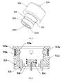
FIG. 5 is a perspective view of the first connector ofFIG. 1 . -
FIG. 6 is a cross-sectional view of the second connector of the electronic cigarette ofFIG. 1 . -
FIG. 7 is a cross-sectional view of another second connector according to a second embodiment. - It will be appreciated that for simplicity and clarity of illustration, where appropriate, reference numerals have been repeated among the different figures to indicate corresponding or analogous elements. In addition, numerous specific details are set forth in order to provide a thorough understanding of the embodiments described herein. However, it will be understood by those of ordinary skill in the art that the embodiments described herein can be practiced without these specific details. In other instances, methods, procedures and components have not been described in detail so as not to obscure the related relevant feature being described. Also, the description is not to be considered as limiting the scope of the embodiments described herein. The drawings are not necessarily to scale and the proportions of certain parts have been exaggerated to better illustrate details and features of the present disclosure.
- The disclosure is illustrated by way of example and not by way of limitation in the figures of the accompanying drawings in which like references indicate similar elements. It should be noted that references to "an" or "one" embodiment in this disclosure are not necessarily to the same embodiment, and such references mean at least one.
- Several definitions that apply throughout this disclosure will now be presented.
- The term "outside" refers to a region that is beyond the outermost confines of a physical object. The term "inside" indicates that at least a portion of a region is partially contained within a boundary formed by the object. The term "substantially" is defined to be essentially conforming to the particular dimension, shape or other word that substantially modifies, such that the component need not be exact. For example, substantially cylindrical means that the object resembles a cylinder, but can have one or more deviations from a true cylinder. The term "comprising," when utilized, means "including, but not necessarily limited to"; it specifically indicates open-ended inclusion or membership in the so-described combination, group, series and the like.
- Referring to
FIGS. 1-2 , anelectronic cigarette 100 includes anatomizer 200 and apower supply 300. Theatomizer 200 is configured (i.e., structured and arranged) for heating tobacco liquid to form aerosol. Thepower supply 300 is configured for providing theatomizer 200 power. Theatomizer 200 includes afirst connector 210, and thepower supply 300 includes asecond connector 310. Thefirst connector 210 is adapted for inserting into thesecond connector 310, and is thus coupled to thesecond connector 310. It is to be understood that in other embodiments, thefirst connector 210 may be arranged in thepower supply 300, and correspondingly, thesecond connector 310 may be provided in theatomizer 200. - Referring to
FIGS. 3-4 , thefirst connector 210 includes acylindrical plug 211. Theplug 211 has arecessed portion 212 in a side surface thereof. Thesecond connector 310 includes aholder 311, a movable component, and a force exerting component. Theholder 311 is configured for receiving theplug 211. The movable component is movably received in asidewall 3111 of theholder 311. The force exerting component is configured for exerting elastic force on the movable component. In the present embodiment, the movable component includes a plurality ofsteel balls 312a. Thesteel balls 312a are capable of ejecting from thesidewall 3111 and retracting relative to thesidewall 3111. When thesteel balls 312a retract to avoid theplug 211, theplug 211 can be inserted into theholder 311 smoothly; when thesteel balls 312a eject to insert into therecessed portion 212, theatomizer 200 is engaged with thepower supply 300. - Referring to
FIG. 5 , thefirst connector 210 further includes anouter electrode 213, and aninner electrode 214. Theinner electrode 214 is arranged in the outer electrode, and is insulated from theouter electrode 213. Theatomizer 200 includes aheating element 220 inside. One end of theheating element 220 is connected to theouter electrode 213, and an opposite end of theheating element 220 is connected to theinner electrode 214. - Also referring to
FIG. 1 andFIG. 6 , thepower supply 300 includes abattery 320 inside. Theholder 311 includes afirst terminal 313 and asecond terminal 314, both of which are connected to thebattery 320 respectively. When thesteel balls 312a are engaged in therecessed portion 212, thefirst terminal 313 is electrically connected with theouter electrode 213, and thesecond terminal 314 is electrically connected with theinner electrode 214. In this way, theatomizer 200 and thepower supply 300 are mechanically and electrically connected via the first and thesecond connectors - Further, the
atomizer 200 defines anair passage 230. Theinner electrode 214 defines acentral hole 2141 communicating with theair passage 230. Air can enter theair passage 230 through thecentral hole 2141. - The
inner electrode 214 includes a flange 2142 (as shown inFIG. 5 ) at one end. An end surface of theflange 2142 is coplanar with an end surface of theplug 211. Accordingly, theinner electrode 214 is in reliable and stable contact with thesecond terminal 314, when theatomizer 200 is coupled to thepower supply 300. - Referring to
FIG. 6 , thefirst terminal 313 is designed as elastic structure. Thefirst terminal 313 is in elastic contact with theouter electrode 213. Accordingly, a connection problem between thefirst terminal 313 and theouter electrode 213, which may be caused by size error, is overcome. Likewise, thesecond terminal 314 is in elastic contact with theinner electrode 214. In the present embodiment, thefirst terminal 313 includes a first pin capable of stretching and shrinking, and thesecond terminal 314 includes a spring. - Further, the first and the
second terminals plate 315. Theplate 315 is engaged with theholder 311 by interference fit. Theplate 315 defines a plurality of air holes 316. Air enters thepower supply 300 from an end of thepower supply 300, passes through the air holes 316 and thecentral hole 2141, and then reaches theatomizer 200. - Further, in the
second connector 310, the force exerting component includes anelastic ring 317a, and thesidewall 3111 of theholder 311 defines anannular groove 318a. Theelastic ring 317a is engaged in theannular groove 318a. Thesidewall 3111 further defines a plurality of mountingholes 319a. The mountingholes 319a extend through thesidewall 3111, and communicate with theannular groove 318a. Thesteel balls 312a are engaged in corresponding mountingholes 319a. Theelastic ring 317a is configured for exerting an elastic force on thesteel balls 312a, so that thesteel balls 312a are tightly engaged in the mountingholes 319a, and part of eachsteel balls 312a protrudes from thesidewall 3111. It is to be understood that a diameter of the mountinghole 319a should be less than that of thesteel ball 312a, thus preventing thesteel ball 312a from falling. - In use, the
atomizer 200 is inserted into thepower supply 300 in such a manner that thefirst connector 210 is engaged with thesecond connector 310. Therefore, it is very convenient to assemble theelectronic cigarette 100. - Referring to
FIG. 7 , asecond connector 310 according to a second embodiment is shown. In the present embodiment, the force exerting component of thesecond connector 310 includes a fixedring 317b and a plurality ofsprings 317c. The fixedring 317b and thesprings 317c replace the aboveelastic ring 317a of the first embodiment. The movable component includes a plurality ofsecond pins 312b. Eachsecond pin 312b includes a front end and a base. The front end is capable of protruding from thesidewall 3111, while the base cannot protrude from thesidewall 3111. Thesidewall 3111 defines anannular groove 318b and a plurality of mountingholes 319b. The mountingholes 319b extend through thesidewall 3111, and communicate with theannular groove 318b. The fixedring 317b is engaged in theannular groove 318b. Thesecond pins 312b are engaged in corresponding mountingholes 319b. Eachspring 317c is arranged between the fixedring 317b and a respectivesecond pin 312b. Thesprings 317c are configured for exerting an elastic force on a correspondingsecond pin 312b, so that thesecond pins 312b are tightly engaged in the mountingholes 319b. It is to be understood that a diameter of the mountinghole 319a should be larger than that of the front end of thesecond pin 312b, and the diameter of the mountinghole 319a should be less than that of the base of thesecond pin 312b, thus preventing thesecond pin 312b from falling out of the mountinghole 319a. - The recessed
portion 212 is arc-shaped in cross-section, and the front end of eachsecond pin 312b is also arc-shaped in cross-section. In this way, the front end of eachsecond pin 312b and the recessedportion 212 are in surface contact. Accordingly, the connection between theatomizer 200 and thepower supply 300 is more stable. - It is understood that the above-described embodiments are intended to illustrate rather than limit the disclosure. Variations may be made to the embodiments and methods without departing from the spirit of the disclosure. Accordingly, it is appropriate that the appended claims be construed broadly and in a manner consistent with the scope of the disclosure.
Claims (16)
- An electronic cigarette comprising:an atomizer comprising one of a first connector and a second connector; anda power supply comprising the other of a first connector and a second connector;wherein the first connector comprises a cylindrical plug, the plug having a recessed portion in a side surface thereof;the second connector comprises a holder, a movable component, and a force exerting component; the holder is configured for receiving the plug, the movable component is movable arranged on a sidewall of the holder, the force exerting component is configured for exerting an elastic force on the movable component; the movable component is configured for ejecting from the sidewall to engage in the recessed portion when the movable component ejecting from the sidewall, and for retracting relative to the sidewall when the plug is inserted into the holder.
- An electronic cigarette of claim 1, wherein the first connector further comprises an outer electrode and an inner electrode, the inner electrode is arranged in the outer electrode, and is insulated from the outer electrode; the atomizer comprises a heating element, one end of the heating element is connected to the outer electrode, and an opposite end of the heating element is connected to the inner electrode.
- An electronic cigarette of claim 2, wherein an atomizer comprises the first connector, a power supply comprises the second connector; the power supply comprises a battery, the holder comprises a first terminal and a second terminal, both of the first terminal and the second terminal are connected to the battery respectively, when the movable component is engaged in the recessed portion, the first terminal is electrically connected to the outer electrode, and the second terminal is electrically connected to the inner electrode.
- An electronic cigarette of claim 3, wherein the atomizer defines an air passage therethrough, and the inner electrode defines a central hole communicating the air passage.
- An electronic cigarette of claim 3, wherein the first terminal is in elastic contact with the outer electrode, and/or the second terminal is in elastic contact with the inner electrode.
- An electronic cigarette of claim 4, wherein the inner electrode includes a flange at one end, and an end surface of the flange is coplanar with an end surface of the plug.
- An electronic cigarette of claim 4, wherein the holder further comprises a plate, the first and the second terminals are both fixed on the plate, and the plate defines a plurality of air holes.
- An electronic cigarette of claim 1, wherein the force exerting component comprises an elastic ring, and the sidewall of the holder defines an annular groove, the movable component comprises a plurality of steel balls, the sidewall further defines a plurality of mounting holes, the mounting holes extend through the sidewall, and communicate with the annular groove. The steel balls are engaged in corresponding mounting holes, the elastic ring is engaged in the annular groove, the elastic ring is configured for exerting an elastic force on the steel balls, so that the steel balls are tightly engaged in the mounting holes, and part of each steel balls protrudes from the sidewall.
- An electronic cigarette of claim 1, wherein the force exerting component comprises a fixed ring and a plurality of springs, the sidewall defines an annular groove and a plurality of mounting holes, the movable component has a plurality of second pins, the mounting holes extend through the sidewall, and communicate with the annular groove, the fixed ring is engaged in the annular groove, the second pins are engaged in corresponding mounting holes. Each spring is arranged between the fixed ring and a respective second pin, the springs are configured for exerting an elastic force on a corresponding second pin, so that the second pins are tightly engaged in the mounting holes, and ends of the second pins protrude from each mounting hole.
- An electronic cigarette of claim 1, wherein the recessed portion is arc-shaped in cross-section.
- An atomizer comprising:one of a first connector and a second connector, wherein the first connector comprises a cylindrical plug, the plug has a recessed portion in a side surface thereof;the second connector comprises a holder, a movable component, and a force exerting component; the holder is configured for receiving the plug, the movable component is movable arranged on a sidewall of the holder, the force exerting component is configured for exerting an elastic force on the movable component; the movable component is configured for ejecting from the sidewall to engage in the recessed portion when the movable component ejecting from the sidewall, and for retracting relative to the sidewall when the plug is inserted into the holder.
- An atomizer of claim 11, wherein the force exerting component comprises an elastic ring, and the sidewall of the holder defines an annular groove, the movable component comprises a plurality of steel balls, the sidewall further defines a plurality of mounting holes, the mounting holes extend through the sidewall, and communicate with the annular groove. The steel balls are engaged in corresponding mounting holes, the elastic ring is engaged in the annular groove, the elastic ring is configured for exerting an elastic force on the steel balls, so that the steel balls are tightly engaged in the mounting holes, and part of each steel balls protrudes from the sidewall.
- An atomizer of claim 11, wherein the force exerting component comprises a fixed ring and a plurality of springs, the sidewall defines an annular groove and a plurality of mounting holes, the movable component has a plurality of second pins, the mounting holes extend through the sidewall, and communicate with the annular groove, the fixed ring is engaged in the annular groove, the second pins are engaged in corresponding mounting holes. Each spring is arranged between the fixed ring and a respective second pin, the springs are configured for exerting an elastic force on a corresponding second pin, so that the second pins are tightly engaged in the mounting holes, and ends of the second pins protrude from each mounting hole.
- A power supply comprising:one of a first connector and a second connector, wherein the first connector comprises a cylindrical plug, the plug has a recessed portion in a side surface thereof;the second connector comprises a holder, a movable component, and a force exerting component; the holder is configured for receiving the plug, the movable component is movable arranged on a sidewall of the holder; the force exerting component is configured for exerting an elastic force on the movable component, and the movable component is configured for ejecting from the sidewall to engage in the recessed portion when the movable component ejecting from the sidewall, and for retracting relative to the sidewall when the plug is inserted into the holder.
- A power supply of claim 14, wherein the force exerting component comprises an elastic ring, and the sidewall of the holder defines an annular groove, the movable component comprises a plurality of steel balls, the sidewall further defines a plurality of mounting holes, the mounting holes extend through the sidewall, and communicate with the annular groove. The steel balls are engaged in corresponding mounting holes, the elastic ring is engaged in the annular groove, the elastic ring is configured for exerting an elastic force on the steel balls, so that the steel balls are tightly engaged in the mounting holes, and part of each steel balls protrudes from the sidewall.
- A power supply of claim 14, wherein the force exerting component comprises a fixed ring and a plurality of springs, the sidewall defines an annular groove and a plurality of mounting holes, the movable component has a plurality of second pins, the mounting holes extend through the sidewall, and communicate with the annular groove, the fixed ring is engaged in the annular groove, the second pins are engaged in corresponding mounting holes. Each spring is arranged between the fixed ring and a respective second pin, the springs are configured for exerting an elastic force on a corresponding second pin, so that the second pins are tightly engaged in the mounting holes, and ends of the second pins protrude from each mounting hole.
Applications Claiming Priority (1)
| Application Number | Priority Date | Filing Date | Title |
|---|---|---|---|
| CN201420247995.7U CN203913391U (en) | 2014-05-15 | 2014-05-15 | Electronic cigarette and electric supply installation |
Publications (2)
| Publication Number | Publication Date |
|---|---|
| EP2944207A1 true EP2944207A1 (en) | 2015-11-18 |
| EP2944207B1 EP2944207B1 (en) | 2023-12-13 |
Family
ID=51809294
Family Applications (1)
| Application Number | Title | Priority Date | Filing Date |
|---|---|---|---|
| EP15167786.1A Active EP2944207B1 (en) | 2014-05-15 | 2015-05-15 | Atomizer, power supply, and electronic cigarette having same |
Country Status (3)
| Country | Link |
|---|---|
| US (1) | US10045563B2 (en) |
| EP (1) | EP2944207B1 (en) |
| CN (1) | CN203913391U (en) |
Cited By (10)
| Publication number | Priority date | Publication date | Assignee | Title |
|---|---|---|---|---|
| EP3419443A4 (en) * | 2016-02-11 | 2019-11-20 | Juul Labs, Inc. | CARTRIDGES SECURELY FIXED FOR VAPORIZATION DEVICES |
| EP3711556A1 (en) * | 2019-03-22 | 2020-09-23 | Nerudia Limited | Smoking substitute system |
| US10865001B2 (en) | 2016-02-11 | 2020-12-15 | Juul Labs, Inc. | Fillable vaporizer cartridge and method of filling |
| US10912331B2 (en) | 2013-12-23 | 2021-02-09 | Juul Labs, Inc. | Vaporization device systems and methods |
| US10912333B2 (en) | 2016-02-25 | 2021-02-09 | Juul Labs, Inc. | Vaporization device control systems and methods |
| US11019685B2 (en) | 2014-02-06 | 2021-05-25 | Juul Labs, Inc. | Vaporization device systems and methods |
| US11337457B2 (en) | 2016-11-30 | 2022-05-24 | Philip Morris Products S.A. | Aerosol-generating system having an outer housing |
| US11752283B2 (en) | 2013-12-23 | 2023-09-12 | Juul Labs, Inc. | Vaporization device systems and methods |
| US11911557B2 (en) | 2018-10-15 | 2024-02-27 | Juul Labs, Inc. | Heating element |
| US12279646B2 (en) | 2014-02-06 | 2025-04-22 | Juul Labs, Inc. | Cartridge of vaporization device systems having unequal transverse cartridge dimensions |
Families Citing this family (35)
| Publication number | Priority date | Publication date | Assignee | Title |
|---|---|---|---|---|
| US10244793B2 (en) | 2005-07-19 | 2019-04-02 | Juul Labs, Inc. | Devices for vaporization of a substance |
| US10279934B2 (en) | 2013-03-15 | 2019-05-07 | Juul Labs, Inc. | Fillable vaporizer cartridge and method of filling |
| US10039321B2 (en) | 2013-11-12 | 2018-08-07 | Vmr Products Llc | Vaporizer |
| US10076139B2 (en) | 2013-12-23 | 2018-09-18 | Juul Labs, Inc. | Vaporizer apparatus |
| US20160366947A1 (en) | 2013-12-23 | 2016-12-22 | James Monsees | Vaporizer apparatus |
| USD842536S1 (en) | 2016-07-28 | 2019-03-05 | Juul Labs, Inc. | Vaporizer cartridge |
| US10159282B2 (en) | 2013-12-23 | 2018-12-25 | Juul Labs, Inc. | Cartridge for use with a vaporizer device |
| USD825102S1 (en) | 2016-07-28 | 2018-08-07 | Juul Labs, Inc. | Vaporizer device with cartridge |
| CN203762295U (en) * | 2014-01-14 | 2014-08-13 | 深圳市合元科技有限公司 | Battery pack used for electronic cigarette and electronic cigarette |
| TWI656848B (en) * | 2014-11-10 | 2019-04-21 | 日商日本煙草產業股份有限公司 | Non-burning flavor inhaler and package |
| KR20250012730A (en) | 2014-12-05 | 2025-01-24 | 쥴 랩스, 인크. | Calibrated dose control |
| CN105982356B (en) * | 2015-02-12 | 2019-06-14 | 深圳市新宜康科技股份有限公司 | Electronic cigarette conductive contact column and elastic conductive contact body |
| CN204540836U (en) * | 2015-04-01 | 2015-08-12 | 深圳市联君烟博士电子技术有限责任公司 | Electronic smoke atomizer and battery rod marble syndeton |
| WO2016210090A1 (en) | 2015-06-25 | 2016-12-29 | Altria Client Services Llc | E-vapor device including at least one of a bayonet connector and a connector with a knurled pattern for forming a welded junction |
| US10405582B2 (en) | 2016-03-10 | 2019-09-10 | Pax Labs, Inc. | Vaporization device with lip sensing |
| USD849996S1 (en) | 2016-06-16 | 2019-05-28 | Pax Labs, Inc. | Vaporizer cartridge |
| USD851830S1 (en) | 2016-06-23 | 2019-06-18 | Pax Labs, Inc. | Combined vaporizer tamp and pick tool |
| USD836541S1 (en) | 2016-06-23 | 2018-12-25 | Pax Labs, Inc. | Charging device |
| US10448667B2 (en) * | 2016-09-29 | 2019-10-22 | Schmidt Innovations GmbH | Closure system for a hookah |
| US10426198B2 (en) * | 2016-10-31 | 2019-10-01 | Altria Client Services Llc | Electrical connector for an electronic vaping device |
| USD887632S1 (en) | 2017-09-14 | 2020-06-16 | Pax Labs, Inc. | Vaporizer cartridge |
| US10729175B2 (en) * | 2018-03-02 | 2020-08-04 | Esquire Properties Trading Inc. | Vaporizer electrical system having a moving electrode with a combined electrical and airflow regulation function |
| JP6569972B1 (en) * | 2018-10-26 | 2019-09-04 | 日本たばこ産業株式会社 | Non-combustion suction device power unit, atomization unit and non-combustion suction device |
| CN111096485A (en) * | 2018-10-26 | 2020-05-05 | 日本烟草产业株式会社 | Power supply unit of non-combustion type suction device, atomization unit and non-combustion type suction device |
| CN111096478A (en) * | 2018-10-26 | 2020-05-05 | 日本烟草产业株式会社 | Atomizing unit and non-combustion aspirator |
| CN109660003B (en) * | 2019-01-15 | 2024-08-20 | 北京史河科技有限公司 | Self-service charging structure and self-service charging system |
| JP2022120203A (en) * | 2019-04-19 | 2022-08-18 | 株式会社村田製作所 | Battery pack, non-combustion type sucking device, electronic apparatus and electric tool |
| CN110297115A (en) * | 2019-06-24 | 2019-10-01 | 广东电网有限责任公司 | A kind of extended pattern electric current split-core type meter |
| KR102718033B1 (en) * | 2019-08-28 | 2024-10-17 | 필립모리스 프로덕츠 에스.에이. | Flare-type susceptor heating array for aerosol generating devices |
| CN211672447U (en) | 2019-12-18 | 2020-10-16 | 深圳市珍烟实业有限公司 | Electronic cigarette atomizer and electronic cigarette |
| EP4099856B1 (en) | 2020-02-04 | 2025-02-26 | Juul Labs, Inc. | Aerosol dispensing device with disposable container |
| CN111955803A (en) * | 2020-08-07 | 2020-11-20 | 深圳麦克韦尔科技有限公司 | Heating element and electronic atomization device adopting same |
| CN115474711B (en) * | 2021-06-16 | 2025-10-10 | 深圳市斯科尔科技股份有限公司 | Atomization device and atomization equipment |
| WO2023225950A1 (en) * | 2022-05-26 | 2023-11-30 | 深圳市华诚达精密工业有限公司 | Electronic atomizer that is convenient to connect |
| USD1024420S1 (en) * | 2022-11-04 | 2024-04-23 | Shenzhen Eigate Technology Co., Ltd. | Electronic cigarette power supply device |
Citations (5)
| Publication number | Priority date | Publication date | Assignee | Title |
|---|---|---|---|---|
| CN202566290U (en) * | 2012-05-10 | 2012-12-05 | 卓尔悦(常州)电子科技有限公司 | Power supply device and electronic cigarette |
| CN203416812U (en) * | 2013-09-09 | 2014-02-05 | 林光榕 | Ball-clamping-type electronic cigarette, connecting component and atomizing component |
| CN203492785U (en) * | 2013-08-06 | 2014-03-26 | 刘秋明 | Electronic cigarette |
| WO2014047826A1 (en) * | 2012-09-27 | 2014-04-03 | Liu Qiuming | Magnetic connection electronic cigarette |
| CN204120231U (en) * | 2014-08-04 | 2015-01-28 | 黄金珍 | Electronic cigarette |
Family Cites Families (14)
| Publication number | Priority date | Publication date | Assignee | Title |
|---|---|---|---|---|
| CN100381083C (en) * | 2003-04-29 | 2008-04-16 | 韩力 | Non-combustible electronic spray cigarette |
| CN201379072Y (en) * | 2009-02-11 | 2010-01-13 | 韩力 | An improved atomized electronic cigarette |
| EP2319334A1 (en) * | 2009-10-27 | 2011-05-11 | Philip Morris Products S.A. | A smoking system having a liquid storage portion |
| US9259035B2 (en) * | 2010-05-15 | 2016-02-16 | R. J. Reynolds Tobacco Company | Solderless personal vaporizing inhaler |
| CN201830900U (en) * | 2010-06-09 | 2011-05-18 | 李永海 | Tobacco juice atomization device for electronic cigarette |
| US8528569B1 (en) * | 2011-06-28 | 2013-09-10 | Kyle D. Newton | Electronic cigarette with liquid reservoir |
| US9854839B2 (en) * | 2012-01-31 | 2018-01-02 | Altria Client Services Llc | Electronic vaping device and method |
| CN202618275U (en) * | 2012-04-01 | 2012-12-26 | 惠州市吉瑞科技有限公司 | Electronic cigarette and suction nozzle thereof |
| WO2014101114A1 (en) * | 2012-12-28 | 2014-07-03 | Liu Qiuming | Electronic cigarette and soft suction rod thereof |
| US20140182612A1 (en) * | 2012-12-28 | 2014-07-03 | Shenzhen Smoore Technology Limited | Electronic atomizing inhalation device |
| CN111642812A (en) * | 2013-06-14 | 2020-09-11 | 尤尔实验室有限公司 | Multiple heating elements with individual vaporizable materials in electronic vaporization devices |
| CN203523808U (en) * | 2013-07-15 | 2014-04-09 | 刘秋明 | Electronic cigarette and electrode assembly |
| CN203446531U (en) * | 2013-07-24 | 2014-02-26 | 刘秋明 | Electronic cigarette |
| CN203482897U (en) * | 2013-08-22 | 2014-03-19 | 刘秋明 | Electronic cigarette |
-
2014
- 2014-05-15 CN CN201420247995.7U patent/CN203913391U/en not_active Expired - Fee Related
-
2015
- 2015-05-15 US US14/714,213 patent/US10045563B2/en active Active
- 2015-05-15 EP EP15167786.1A patent/EP2944207B1/en active Active
Patent Citations (5)
| Publication number | Priority date | Publication date | Assignee | Title |
|---|---|---|---|---|
| CN202566290U (en) * | 2012-05-10 | 2012-12-05 | 卓尔悦(常州)电子科技有限公司 | Power supply device and electronic cigarette |
| WO2014047826A1 (en) * | 2012-09-27 | 2014-04-03 | Liu Qiuming | Magnetic connection electronic cigarette |
| CN203492785U (en) * | 2013-08-06 | 2014-03-26 | 刘秋明 | Electronic cigarette |
| CN203416812U (en) * | 2013-09-09 | 2014-02-05 | 林光榕 | Ball-clamping-type electronic cigarette, connecting component and atomizing component |
| CN204120231U (en) * | 2014-08-04 | 2015-01-28 | 黄金珍 | Electronic cigarette |
Cited By (17)
| Publication number | Priority date | Publication date | Assignee | Title |
|---|---|---|---|---|
| US10993471B2 (en) | 2013-12-23 | 2021-05-04 | Juul Labs, Inc. | Vaporization device systems and methods |
| US10912331B2 (en) | 2013-12-23 | 2021-02-09 | Juul Labs, Inc. | Vaporization device systems and methods |
| US10986867B2 (en) | 2013-12-23 | 2021-04-27 | Juul Labs, Inc. | Vaporization device systems and methods |
| US11992044B2 (en) | 2013-12-23 | 2024-05-28 | Juul Labs, Inc. | Vaporization device systems and methods |
| US11752283B2 (en) | 2013-12-23 | 2023-09-12 | Juul Labs, Inc. | Vaporization device systems and methods |
| US12279646B2 (en) | 2014-02-06 | 2025-04-22 | Juul Labs, Inc. | Cartridge of vaporization device systems having unequal transverse cartridge dimensions |
| US11019685B2 (en) | 2014-02-06 | 2021-05-25 | Juul Labs, Inc. | Vaporization device systems and methods |
| US11452177B2 (en) | 2014-02-06 | 2022-09-20 | Juul Labs, Inc. | Vaporization device systems and methods |
| US10865001B2 (en) | 2016-02-11 | 2020-12-15 | Juul Labs, Inc. | Fillable vaporizer cartridge and method of filling |
| EP3419443A4 (en) * | 2016-02-11 | 2019-11-20 | Juul Labs, Inc. | CARTRIDGES SECURELY FIXED FOR VAPORIZATION DEVICES |
| US11751605B2 (en) | 2016-02-11 | 2023-09-12 | Juul Labs, Inc. | Securely attaching cartridges for vaporizer devices |
| US10912333B2 (en) | 2016-02-25 | 2021-02-09 | Juul Labs, Inc. | Vaporization device control systems and methods |
| US12063973B2 (en) | 2016-02-25 | 2024-08-20 | Juul Labs, Inc. | Vaporization device control systems and methods |
| US11337457B2 (en) | 2016-11-30 | 2022-05-24 | Philip Morris Products S.A. | Aerosol-generating system having an outer housing |
| US11911557B2 (en) | 2018-10-15 | 2024-02-27 | Juul Labs, Inc. | Heating element |
| US12420035B2 (en) | 2018-10-15 | 2025-09-23 | Juul Labs, Inc. | Atomizer assembly for a vaporizer device |
| EP3711556A1 (en) * | 2019-03-22 | 2020-09-23 | Nerudia Limited | Smoking substitute system |
Also Published As
| Publication number | Publication date |
|---|---|
| CN203913391U (en) | 2014-11-05 |
| EP2944207B1 (en) | 2023-12-13 |
| US20150327597A1 (en) | 2015-11-19 |
| US10045563B2 (en) | 2018-08-14 |
Similar Documents
| Publication | Publication Date | Title |
|---|---|---|
| EP2944207B1 (en) | Atomizer, power supply, and electronic cigarette having same | |
| EP3011850B1 (en) | Atomizer and aerosol inhaling device having same | |
| EP3326473B1 (en) | Charger for electronic cigarette with multiple charging ports | |
| US9236682B2 (en) | Cylindrical electric connector with biased contact | |
| EP3179828A1 (en) | Cigarette heating device | |
| EP3174367B1 (en) | Heating assembly and cigarette heating device having same | |
| US7641489B1 (en) | Safety plug socket | |
| EP3216358A1 (en) | Connector, power supply, atomizer and electronic cigarette having same | |
| US8382533B2 (en) | Electrically conducting terminal | |
| US8529274B2 (en) | Electrical coupler | |
| US9490655B2 (en) | Wireless charging device for vehicles | |
| CN103618168A (en) | Plug and socket of double-way unlocking circular connector | |
| CN113363751A (en) | Power connector with crown spring | |
| CN202495602U (en) | Cleft slot structure on electric connector jack | |
| CN108173092B (en) | POGO PIN coaxial connector for radio frequency | |
| JP6130484B2 (en) | System for current transmission | |
| CN105119103B (en) | A kind of socket, the plug of connector used for electric vehicle | |
| CN207269069U (en) | A kind of high current terminal structure | |
| CN108879161A (en) | A kind of high current terminal structure | |
| CN211907837U (en) | Electric connector and Bluetooth headset | |
| CN203984633U (en) | A kind of universal rotary shaft Earphone joint | |
| US8905796B2 (en) | Power supply plug structure | |
| NL2012812B1 (en) | High-speed data connector. | |
| CN102025064B (en) | Transition jack and filter electrical connector using the transition jack | |
| CN103367964A (en) | Insulated Terminal Blocks for Connectors |
Legal Events
| Date | Code | Title | Description |
|---|---|---|---|
| PUAI | Public reference made under article 153(3) epc to a published international application that has entered the european phase |
Free format text: ORIGINAL CODE: 0009012 |
|
| 17P | Request for examination filed |
Effective date: 20150516 |
|
| AK | Designated contracting states |
Kind code of ref document: A1 Designated state(s): AL AT BE BG CH CY CZ DE DK EE ES FI FR GB GR HR HU IE IS IT LI LT LU LV MC MK MT NL NO PL PT RO RS SE SI SK SM TR |
|
| AX | Request for extension of the european patent |
Extension state: BA ME |
|
| STAA | Information on the status of an ep patent application or granted ep patent |
Free format text: STATUS: EXAMINATION IS IN PROGRESS |
|
| 17Q | First examination report despatched |
Effective date: 20181217 |
|
| GRAP | Despatch of communication of intention to grant a patent |
Free format text: ORIGINAL CODE: EPIDOSNIGR1 |
|
| STAA | Information on the status of an ep patent application or granted ep patent |
Free format text: STATUS: GRANT OF PATENT IS INTENDED |
|
| INTG | Intention to grant announced |
Effective date: 20230703 |
|
| GRAS | Grant fee paid |
Free format text: ORIGINAL CODE: EPIDOSNIGR3 |
|
| GRAA | (expected) grant |
Free format text: ORIGINAL CODE: 0009210 |
|
| STAA | Information on the status of an ep patent application or granted ep patent |
Free format text: STATUS: THE PATENT HAS BEEN GRANTED |
|
| AK | Designated contracting states |
Kind code of ref document: B1 Designated state(s): AL AT BE BG CH CY CZ DE DK EE ES FI FR GB GR HR HU IE IS IT LI LT LU LV MC MK MT NL NO PL PT RO RS SE SI SK SM TR |
|
| REG | Reference to a national code |
Ref country code: GB Ref legal event code: FG4D |
|
| REG | Reference to a national code |
Ref country code: CH Ref legal event code: EP |
|
| REG | Reference to a national code |
Ref country code: DE Ref legal event code: R096 Ref document number: 602015086906 Country of ref document: DE |
|
| REG | Reference to a national code |
Ref country code: IE Ref legal event code: FG4D |
|
| PG25 | Lapsed in a contracting state [announced via postgrant information from national office to epo] |
Ref country code: GR Free format text: LAPSE BECAUSE OF FAILURE TO SUBMIT A TRANSLATION OF THE DESCRIPTION OR TO PAY THE FEE WITHIN THE PRESCRIBED TIME-LIMIT Effective date: 20240314 |
|
| REG | Reference to a national code |
Ref country code: LT Ref legal event code: MG9D |
|
| PG25 | Lapsed in a contracting state [announced via postgrant information from national office to epo] |
Ref country code: LT Free format text: LAPSE BECAUSE OF FAILURE TO SUBMIT A TRANSLATION OF THE DESCRIPTION OR TO PAY THE FEE WITHIN THE PRESCRIBED TIME-LIMIT Effective date: 20231213 |
|
| REG | Reference to a national code |
Ref country code: NL Ref legal event code: MP Effective date: 20231213 |
|
| PG25 | Lapsed in a contracting state [announced via postgrant information from national office to epo] |
Ref country code: ES Free format text: LAPSE BECAUSE OF FAILURE TO SUBMIT A TRANSLATION OF THE DESCRIPTION OR TO PAY THE FEE WITHIN THE PRESCRIBED TIME-LIMIT Effective date: 20231213 |
|
| PG25 | Lapsed in a contracting state [announced via postgrant information from national office to epo] |
Ref country code: LT Free format text: LAPSE BECAUSE OF FAILURE TO SUBMIT A TRANSLATION OF THE DESCRIPTION OR TO PAY THE FEE WITHIN THE PRESCRIBED TIME-LIMIT Effective date: 20231213 Ref country code: GR Free format text: LAPSE BECAUSE OF FAILURE TO SUBMIT A TRANSLATION OF THE DESCRIPTION OR TO PAY THE FEE WITHIN THE PRESCRIBED TIME-LIMIT Effective date: 20240314 Ref country code: ES Free format text: LAPSE BECAUSE OF FAILURE TO SUBMIT A TRANSLATION OF THE DESCRIPTION OR TO PAY THE FEE WITHIN THE PRESCRIBED TIME-LIMIT Effective date: 20231213 Ref country code: BG Free format text: LAPSE BECAUSE OF FAILURE TO SUBMIT A TRANSLATION OF THE DESCRIPTION OR TO PAY THE FEE WITHIN THE PRESCRIBED TIME-LIMIT Effective date: 20240313 |
|
| REG | Reference to a national code |
Ref country code: AT Ref legal event code: MK05 Ref document number: 1639668 Country of ref document: AT Kind code of ref document: T Effective date: 20231213 |
|
| PG25 | Lapsed in a contracting state [announced via postgrant information from national office to epo] |
Ref country code: NL Free format text: LAPSE BECAUSE OF FAILURE TO SUBMIT A TRANSLATION OF THE DESCRIPTION OR TO PAY THE FEE WITHIN THE PRESCRIBED TIME-LIMIT Effective date: 20231213 |
|
| PG25 | Lapsed in a contracting state [announced via postgrant information from national office to epo] |
Ref country code: SE Free format text: LAPSE BECAUSE OF FAILURE TO SUBMIT A TRANSLATION OF THE DESCRIPTION OR TO PAY THE FEE WITHIN THE PRESCRIBED TIME-LIMIT Effective date: 20231213 Ref country code: RS Free format text: LAPSE BECAUSE OF FAILURE TO SUBMIT A TRANSLATION OF THE DESCRIPTION OR TO PAY THE FEE WITHIN THE PRESCRIBED TIME-LIMIT Effective date: 20231213 Ref country code: NO Free format text: LAPSE BECAUSE OF FAILURE TO SUBMIT A TRANSLATION OF THE DESCRIPTION OR TO PAY THE FEE WITHIN THE PRESCRIBED TIME-LIMIT Effective date: 20240313 Ref country code: NL Free format text: LAPSE BECAUSE OF FAILURE TO SUBMIT A TRANSLATION OF THE DESCRIPTION OR TO PAY THE FEE WITHIN THE PRESCRIBED TIME-LIMIT Effective date: 20231213 Ref country code: LV Free format text: LAPSE BECAUSE OF FAILURE TO SUBMIT A TRANSLATION OF THE DESCRIPTION OR TO PAY THE FEE WITHIN THE PRESCRIBED TIME-LIMIT Effective date: 20231213 Ref country code: HR Free format text: LAPSE BECAUSE OF FAILURE TO SUBMIT A TRANSLATION OF THE DESCRIPTION OR TO PAY THE FEE WITHIN THE PRESCRIBED TIME-LIMIT Effective date: 20231213 |
|
| PG25 | Lapsed in a contracting state [announced via postgrant information from national office to epo] |
Ref country code: IS Free format text: LAPSE BECAUSE OF FAILURE TO SUBMIT A TRANSLATION OF THE DESCRIPTION OR TO PAY THE FEE WITHIN THE PRESCRIBED TIME-LIMIT Effective date: 20240413 |
|
| PG25 | Lapsed in a contracting state [announced via postgrant information from national office to epo] |
Ref country code: AT Free format text: LAPSE BECAUSE OF FAILURE TO SUBMIT A TRANSLATION OF THE DESCRIPTION OR TO PAY THE FEE WITHIN THE PRESCRIBED TIME-LIMIT Effective date: 20231213 Ref country code: CZ Free format text: LAPSE BECAUSE OF FAILURE TO SUBMIT A TRANSLATION OF THE DESCRIPTION OR TO PAY THE FEE WITHIN THE PRESCRIBED TIME-LIMIT Effective date: 20231213 |
|
| PG25 | Lapsed in a contracting state [announced via postgrant information from national office to epo] |
Ref country code: SK Free format text: LAPSE BECAUSE OF FAILURE TO SUBMIT A TRANSLATION OF THE DESCRIPTION OR TO PAY THE FEE WITHIN THE PRESCRIBED TIME-LIMIT Effective date: 20231213 |
|
| PG25 | Lapsed in a contracting state [announced via postgrant information from national office to epo] |
Ref country code: SM Free format text: LAPSE BECAUSE OF FAILURE TO SUBMIT A TRANSLATION OF THE DESCRIPTION OR TO PAY THE FEE WITHIN THE PRESCRIBED TIME-LIMIT Effective date: 20231213 Ref country code: SK Free format text: LAPSE BECAUSE OF FAILURE TO SUBMIT A TRANSLATION OF THE DESCRIPTION OR TO PAY THE FEE WITHIN THE PRESCRIBED TIME-LIMIT Effective date: 20231213 Ref country code: RO Free format text: LAPSE BECAUSE OF FAILURE TO SUBMIT A TRANSLATION OF THE DESCRIPTION OR TO PAY THE FEE WITHIN THE PRESCRIBED TIME-LIMIT Effective date: 20231213 Ref country code: IT Free format text: LAPSE BECAUSE OF FAILURE TO SUBMIT A TRANSLATION OF THE DESCRIPTION OR TO PAY THE FEE WITHIN THE PRESCRIBED TIME-LIMIT Effective date: 20231213 Ref country code: IS Free format text: LAPSE BECAUSE OF FAILURE TO SUBMIT A TRANSLATION OF THE DESCRIPTION OR TO PAY THE FEE WITHIN THE PRESCRIBED TIME-LIMIT Effective date: 20240413 Ref country code: EE Free format text: LAPSE BECAUSE OF FAILURE TO SUBMIT A TRANSLATION OF THE DESCRIPTION OR TO PAY THE FEE WITHIN THE PRESCRIBED TIME-LIMIT Effective date: 20231213 Ref country code: CZ Free format text: LAPSE BECAUSE OF FAILURE TO SUBMIT A TRANSLATION OF THE DESCRIPTION OR TO PAY THE FEE WITHIN THE PRESCRIBED TIME-LIMIT Effective date: 20231213 Ref country code: AT Free format text: LAPSE BECAUSE OF FAILURE TO SUBMIT A TRANSLATION OF THE DESCRIPTION OR TO PAY THE FEE WITHIN THE PRESCRIBED TIME-LIMIT Effective date: 20231213 |
|
| PG25 | Lapsed in a contracting state [announced via postgrant information from national office to epo] |
Ref country code: PT Free format text: LAPSE BECAUSE OF FAILURE TO SUBMIT A TRANSLATION OF THE DESCRIPTION OR TO PAY THE FEE WITHIN THE PRESCRIBED TIME-LIMIT Effective date: 20240415 Ref country code: PL Free format text: LAPSE BECAUSE OF FAILURE TO SUBMIT A TRANSLATION OF THE DESCRIPTION OR TO PAY THE FEE WITHIN THE PRESCRIBED TIME-LIMIT Effective date: 20231213 |
|
| PG25 | Lapsed in a contracting state [announced via postgrant information from national office to epo] |
Ref country code: PT Free format text: LAPSE BECAUSE OF FAILURE TO SUBMIT A TRANSLATION OF THE DESCRIPTION OR TO PAY THE FEE WITHIN THE PRESCRIBED TIME-LIMIT Effective date: 20240415 Ref country code: PL Free format text: LAPSE BECAUSE OF FAILURE TO SUBMIT A TRANSLATION OF THE DESCRIPTION OR TO PAY THE FEE WITHIN THE PRESCRIBED TIME-LIMIT Effective date: 20231213 |
|
| REG | Reference to a national code |
Ref country code: DE Ref legal event code: R097 Ref document number: 602015086906 Country of ref document: DE |
|
| PG25 | Lapsed in a contracting state [announced via postgrant information from national office to epo] |
Ref country code: DK Free format text: LAPSE BECAUSE OF FAILURE TO SUBMIT A TRANSLATION OF THE DESCRIPTION OR TO PAY THE FEE WITHIN THE PRESCRIBED TIME-LIMIT Effective date: 20231213 |
|
| PLBE | No opposition filed within time limit |
Free format text: ORIGINAL CODE: 0009261 |
|
| STAA | Information on the status of an ep patent application or granted ep patent |
Free format text: STATUS: NO OPPOSITION FILED WITHIN TIME LIMIT |
|
| PG25 | Lapsed in a contracting state [announced via postgrant information from national office to epo] |
Ref country code: SI Free format text: LAPSE BECAUSE OF FAILURE TO SUBMIT A TRANSLATION OF THE DESCRIPTION OR TO PAY THE FEE WITHIN THE PRESCRIBED TIME-LIMIT Effective date: 20231213 |
|
| PG25 | Lapsed in a contracting state [announced via postgrant information from national office to epo] |
Ref country code: SI Free format text: LAPSE BECAUSE OF FAILURE TO SUBMIT A TRANSLATION OF THE DESCRIPTION OR TO PAY THE FEE WITHIN THE PRESCRIBED TIME-LIMIT Effective date: 20231213 Ref country code: DK Free format text: LAPSE BECAUSE OF FAILURE TO SUBMIT A TRANSLATION OF THE DESCRIPTION OR TO PAY THE FEE WITHIN THE PRESCRIBED TIME-LIMIT Effective date: 20231213 |
|
| 26N | No opposition filed |
Effective date: 20240916 |
|
| REG | Reference to a national code |
Ref country code: CH Ref legal event code: PL |
|
| PG25 | Lapsed in a contracting state [announced via postgrant information from national office to epo] |
Ref country code: MC Free format text: LAPSE BECAUSE OF FAILURE TO SUBMIT A TRANSLATION OF THE DESCRIPTION OR TO PAY THE FEE WITHIN THE PRESCRIBED TIME-LIMIT Effective date: 20231213 |
|
| PG25 | Lapsed in a contracting state [announced via postgrant information from national office to epo] |
Ref country code: LU Free format text: LAPSE BECAUSE OF NON-PAYMENT OF DUE FEES Effective date: 20240515 |
|
| PG25 | Lapsed in a contracting state [announced via postgrant information from national office to epo] |
Ref country code: MC Free format text: LAPSE BECAUSE OF FAILURE TO SUBMIT A TRANSLATION OF THE DESCRIPTION OR TO PAY THE FEE WITHIN THE PRESCRIBED TIME-LIMIT Effective date: 20231213 Ref country code: LU Free format text: LAPSE BECAUSE OF NON-PAYMENT OF DUE FEES Effective date: 20240515 Ref country code: CH Free format text: LAPSE BECAUSE OF NON-PAYMENT OF DUE FEES Effective date: 20240531 |
|
| REG | Reference to a national code |
Ref country code: BE Ref legal event code: MM Effective date: 20240531 |
|
| P01 | Opt-out of the competence of the unified patent court (upc) registered |
Free format text: CASE NUMBER: APP_5160/2025 Effective date: 20250130 |
|
| PG25 | Lapsed in a contracting state [announced via postgrant information from national office to epo] |
Ref country code: IE Free format text: LAPSE BECAUSE OF NON-PAYMENT OF DUE FEES Effective date: 20240515 |
|
| PG25 | Lapsed in a contracting state [announced via postgrant information from national office to epo] |
Ref country code: BE Free format text: LAPSE BECAUSE OF NON-PAYMENT OF DUE FEES Effective date: 20240531 |
|
| PGFP | Annual fee paid to national office [announced via postgrant information from national office to epo] |
Ref country code: DE Payment date: 20250513 Year of fee payment: 11 |
|
| PGFP | Annual fee paid to national office [announced via postgrant information from national office to epo] |
Ref country code: GB Payment date: 20250521 Year of fee payment: 11 |
|
| PGFP | Annual fee paid to national office [announced via postgrant information from national office to epo] |
Ref country code: FR Payment date: 20250530 Year of fee payment: 11 |
|
| PG25 | Lapsed in a contracting state [announced via postgrant information from national office to epo] |
Ref country code: CY Free format text: LAPSE BECAUSE OF FAILURE TO SUBMIT A TRANSLATION OF THE DESCRIPTION OR TO PAY THE FEE WITHIN THE PRESCRIBED TIME-LIMIT; INVALID AB INITIO Effective date: 20150515 |
|
| PG25 | Lapsed in a contracting state [announced via postgrant information from national office to epo] |
Ref country code: HU Free format text: LAPSE BECAUSE OF FAILURE TO SUBMIT A TRANSLATION OF THE DESCRIPTION OR TO PAY THE FEE WITHIN THE PRESCRIBED TIME-LIMIT; INVALID AB INITIO Effective date: 20150515 |
|
| PG25 | Lapsed in a contracting state [announced via postgrant information from national office to epo] |
Ref country code: FI Free format text: LAPSE BECAUSE OF FAILURE TO SUBMIT A TRANSLATION OF THE DESCRIPTION OR TO PAY THE FEE WITHIN THE PRESCRIBED TIME-LIMIT Effective date: 20231213 |