EP2943996B1 - Method for air-to-ground data link antenna self calibration - Google Patents
Method for air-to-ground data link antenna self calibration Download PDFInfo
- Publication number
- EP2943996B1 EP2943996B1 EP14702147.1A EP14702147A EP2943996B1 EP 2943996 B1 EP2943996 B1 EP 2943996B1 EP 14702147 A EP14702147 A EP 14702147A EP 2943996 B1 EP2943996 B1 EP 2943996B1
- Authority
- EP
- European Patent Office
- Prior art keywords
- aircraft
- antenna
- base station
- bts
- amplitude
- Prior art date
- Legal status (The legal status is an assumption and is not a legal conclusion. Google has not performed a legal analysis and makes no representation as to the accuracy of the status listed.)
- Active
Links
- 238000000034 method Methods 0.000 title claims description 37
- 238000005259 measurement Methods 0.000 claims description 41
- 238000007670 refining Methods 0.000 claims description 15
- 238000004590 computer program Methods 0.000 claims description 8
- 230000000694 effects Effects 0.000 claims description 7
- 238000004891 communication Methods 0.000 description 59
- 230000001413 cellular effect Effects 0.000 description 13
- 230000005540 biological transmission Effects 0.000 description 12
- 230000006870 function Effects 0.000 description 11
- 238000013461 design Methods 0.000 description 4
- 238000012545 processing Methods 0.000 description 4
- 230000001154 acute effect Effects 0.000 description 3
- 230000015556 catabolic process Effects 0.000 description 3
- 238000006731 degradation reaction Methods 0.000 description 3
- 238000010586 diagram Methods 0.000 description 3
- 238000012937 correction Methods 0.000 description 2
- 229920001690 polydopamine Polymers 0.000 description 2
- 238000001228 spectrum Methods 0.000 description 2
- 238000012546 transfer Methods 0.000 description 2
- 208000004350 Strabismus Diseases 0.000 description 1
- 238000013459 approach Methods 0.000 description 1
- 238000003491 array Methods 0.000 description 1
- 230000015572 biosynthetic process Effects 0.000 description 1
- 230000008859 change Effects 0.000 description 1
- 238000010276 construction Methods 0.000 description 1
- 230000005574 cross-species transmission Effects 0.000 description 1
- 230000007423 decrease Effects 0.000 description 1
- 230000000593 degrading effect Effects 0.000 description 1
- 230000001419 dependent effect Effects 0.000 description 1
- 230000009977 dual effect Effects 0.000 description 1
- 230000003993 interaction Effects 0.000 description 1
- 230000002452 interceptive effect Effects 0.000 description 1
- 238000002044 microwave spectrum Methods 0.000 description 1
- 238000012986 modification Methods 0.000 description 1
- 230000004048 modification Effects 0.000 description 1
- 230000003287 optical effect Effects 0.000 description 1
- 238000005457 optimization Methods 0.000 description 1
- 230000008520 organization Effects 0.000 description 1
- 230000001151 other effect Effects 0.000 description 1
- 239000005022 packaging material Substances 0.000 description 1
- 230000008569 process Effects 0.000 description 1
- 230000001105 regulatory effect Effects 0.000 description 1
- 230000003362 replicative effect Effects 0.000 description 1
- 238000005070 sampling Methods 0.000 description 1
- 230000002194 synthesizing effect Effects 0.000 description 1
Images


Classifications
-
- H—ELECTRICITY
- H01—ELECTRIC ELEMENTS
- H01Q—ANTENNAS, i.e. RADIO AERIALS
- H01Q3/00—Arrangements for changing or varying the orientation or the shape of the directional pattern of the waves radiated from an antenna or antenna system
- H01Q3/26—Arrangements for changing or varying the orientation or the shape of the directional pattern of the waves radiated from an antenna or antenna system varying the relative phase or relative amplitude of energisation between two or more active radiating elements; varying the distribution of energy across a radiating aperture
- H01Q3/2605—Array of radiating elements provided with a feedback control over the element weights, e.g. adaptive arrays
-
- H—ELECTRICITY
- H04—ELECTRIC COMMUNICATION TECHNIQUE
- H04B—TRANSMISSION
- H04B7/00—Radio transmission systems, i.e. using radiation field
- H04B7/02—Diversity systems; Multi-antenna system, i.e. transmission or reception using multiple antennas
- H04B7/04—Diversity systems; Multi-antenna system, i.e. transmission or reception using multiple antennas using two or more spaced independent antennas
- H04B7/06—Diversity systems; Multi-antenna system, i.e. transmission or reception using multiple antennas using two or more spaced independent antennas at the transmitting station
- H04B7/0613—Diversity systems; Multi-antenna system, i.e. transmission or reception using multiple antennas using two or more spaced independent antennas at the transmitting station using simultaneous transmission
- H04B7/0615—Diversity systems; Multi-antenna system, i.e. transmission or reception using multiple antennas using two or more spaced independent antennas at the transmitting station using simultaneous transmission of weighted versions of same signal
- H04B7/0617—Diversity systems; Multi-antenna system, i.e. transmission or reception using multiple antennas using two or more spaced independent antennas at the transmitting station using simultaneous transmission of weighted versions of same signal for beam forming
-
- H—ELECTRICITY
- H04—ELECTRIC COMMUNICATION TECHNIQUE
- H04B—TRANSMISSION
- H04B7/00—Radio transmission systems, i.e. using radiation field
- H04B7/14—Relay systems
- H04B7/15—Active relay systems
- H04B7/185—Space-based or airborne stations; Stations for satellite systems
- H04B7/18502—Airborne stations
- H04B7/18506—Communications with or from aircraft, i.e. aeronautical mobile service
-
- H—ELECTRICITY
- H04—ELECTRIC COMMUNICATION TECHNIQUE
- H04W—WIRELESS COMMUNICATION NETWORKS
- H04W36/00—Hand-off or reselection arrangements
- H04W36/08—Reselecting an access point
- H04W36/085—Reselecting an access point involving beams of access points
-
- H—ELECTRICITY
- H04—ELECTRIC COMMUNICATION TECHNIQUE
- H04W—WIRELESS COMMUNICATION NETWORKS
- H04W36/00—Hand-off or reselection arrangements
- H04W36/16—Performing reselection for specific purposes
- H04W36/18—Performing reselection for specific purposes for allowing seamless reselection, e.g. soft reselection
-
- H—ELECTRICITY
- H04—ELECTRIC COMMUNICATION TECHNIQUE
- H04W—WIRELESS COMMUNICATION NETWORKS
- H04W36/00—Hand-off or reselection arrangements
- H04W36/24—Reselection being triggered by specific parameters
- H04W36/32—Reselection being triggered by specific parameters by location or mobility data, e.g. speed data
- H04W36/328—Reselection being triggered by specific parameters by location or mobility data, e.g. speed data by altitude
-
- H—ELECTRICITY
- H04—ELECTRIC COMMUNICATION TECHNIQUE
- H04W—WIRELESS COMMUNICATION NETWORKS
- H04W36/00—Hand-off or reselection arrangements
- H04W36/0005—Control or signalling for completing the hand-off
- H04W36/0055—Transmission or use of information for re-establishing the radio link
- H04W36/0058—Transmission of hand-off measurement information, e.g. measurement reports
Definitions
- aspects of the present disclosure relate to air-to-ground communication systems, and more particularly to an air-to-ground communications system adapted for use with an airborne mobile platform that accomplishes soft hand offs between terrestrial base transceiver stations in a cellular network while the mobile platform is in flight.
- Wireless communication networks are widely deployed to provide various communication services such as telephony, video, data, messaging, broadcasts, and so on.
- Such networks which are usually multiple access networks, support communications for multiple users by sharing the available network resources.
- Such networks are terrestrial-based networks, however, in recent years, publicly accessible networks are being made available for passengers on commercial air transportation, e.g., airplanes and other aircraft.
- Such services are typically known as air-to-ground (ATG) communication services, and may provide such services as broadband data, voice communication, and entertainment such as streaming movies or music.
- ATG services and networks are similar to currently deployed terrestrial cellular and other wireless networks, there are aspects of ATG networks that differ from these networks.
- each aircraft is serviced by a particular base transceiver station (BTS) until signal quality, signal strength, or available bandwidth from that BTS is insufficient, at which time service is transferred to another BTS.
- BTS base transceiver station
- Such a transfer is typically called a "handoff,” similar to handoffs that occur in terrestrial cellular networks for cellular devices (handsets, PDAs, etc.) when such devices are mobile.
- Aircraft typically use a single transceiver having an antenna mounted on the undercarriage of the aircraft to communicate with the BTS.
- BTS antenna patterns are usually designed to service terrestrial customers, and the beam patterns at a given BTS are usually not arranged to service ATG communications traffic.
- typical cellular and mobile devices use antenna patterns that transmit power in all directions, and if such antennas had high enough gain patterns to communicate directly with a terrestrial BTS, such transmissions would cause interference into all BTS sites within a line of sight of transmission of the cellular device.
- the line-of-sight transmission for a device increases when the transmitter/antenna pattern is at altitude, thus further complicating the interference problem.
- Increased interference also reduces data bandwidth, which creates lower data throughput in an ATG system that can use cellular telephones and other mobile devices directly.
- the antennas used in ATG systems are typically "directional" antennas, where the antenna on the aircraft directs the outgoing transmission in certain directions, and the BTS antenna also directs the transmission power in the direction of aircraft in the BTS service area.
- the aircraft antenna receives the omnidirectional transmissions from the cellular telephones on board, and the aircraft antenna directs these transmissions toward a specific BTS antenna, which reduces interference and increases data throughput.
- the aircraft service is handed off to another BTS in order to maintain communication with the devices on board that aircraft.
- Such a handoff should occur before communication is lost with the serving BTS to ensure continuous communication channels for the devices on board.
- Such communication channels are difficult to maintain without interaction between the aircraft antenna and the BTS antennas, because signal strengths and signal quality are typically not known.
- An embodiment method comprises synthesizing a plurality of virtual antennas from a single physical antenna, wherein a total number of virtual antennas is less than a total number of antenna elements in the physical antenna, transmitting pilot signals on the plurality of virtual antennas, receiving, from a user equipment, a pre-coding control indicator based on the transmitted pilot signals, determining a multiple-input multiple output pre-coding vector based on the pre-coding control indicator, and transmitting user data modulated by the pre-coding vector to the user equipment via the plurality of virtual antennas.
- Such an antenna array includes higher-gain antenna and lower-gain antenna.
- the beamforming antenna both higher-gain and lower-gain, are designed to be able to transmit to and receive from another transceiver.
- the higher-gain antenna may be designed to form a more directional beam substantially closer to the horizon; whereas the lower-gain antenna is capable of forming a less directional beam at a distance further from the horizon, In both cases, the antenna may form their respective beams anywhere in the 360 degrees horizontally around the antenna array.
- the higher-gain antenna may include a coverage area from the horizon to a substantially acute angle from the horizon in the vertical direction.; In contrast, the lower-gain antenna may have coverage from the substantially acute angle from the horizon to substantially vertical. The substantially acute angle may be approximately 10 degrees in some cases. In some cases the lower-gain antenna may include four elements. Likewise, in some embodiments, the higher-gain antenna may include four elements as well.
- Document US 2003/197637 A1 refers to a cross-link antenna system including a plurality of spacecraft in a constellation is provided.
- Each of the spacecraft includes an antenna.
- One or more of the antennas has a number of antenna elements that can be controllably energized. Determined or selected phases and amplitudes can be individually applied through phase shifters and amplifiers to the antenna elements.
- location information is obtained for the transmit spacecraft and each of the beam receiving spacecraft.
- attitude information for each receive spacecraft is found and location information associated with each of the antenna elements for each receive antenna is obtained. Based on such information, during each time interval in which one of the spacecraft in the constellation is sending a transmit beam, each of the other spacecraft in the constellation controls its receive beam in the direction of the transmit beam.
- Document US 2010/123625 A1 refers to systems and methods for operating a communications system.
- the methods involve computing one or more complex weights to be applied to transmit signals and receive signals by beamformers.
- the complex weights are based at least on configuration data for the communications system.
- the methods also involve applying a first plurality of weight corrections to the complex weights based on phasing errors occurring in a communication path inclusive of a control system and antenna elements.
- the methods further involve applying a second plurality of weight corrections to the complex weights based on phase differences at the antenna elements relative to a reference location for the receive signals.
- Document US 2009/100476 A1 refers to an aircraft in-flight entertainment (IFE) system for an aircraft includes a radome to be carried by the aircraft, and a dual-beam satellite antenna and at least one positioner coupled thereto to be carried by the aircraft and protected by the radome.
- the dual-beam satellite antenna is to generate dual antenna beams for television programming and Internet data from respective spaced apart satellites.
- the dual-beam satellite antenna includes a first aperture for receiving the television programming, and a second aperture adjacent the first aperture for receiving the Internet data.
- a television programming distribution system is to be carried by the aircraft and coupled to the dual-beam satellite antenna to provide television programming within the aircraft.
- At least one access point is to be carried by the aircraft and coupled to the dual-beam 0satellite antenna to provide a wireless local area network (WLAN) within the aircraft for the Internet data.
- WLAN wireless local area network
- the present disclosure describes methods, apparatuses, and computer program products for refining beam patterns of antennas.
- a method of refining a beam pattern of a base station antenna configured to communicate with multiple aircraft in which interference to adjacent beams from the base station is reduced receives reports of measurements of pilot signals from each of the aircraft, the received measurements of pilot signals having been transmitted by the base station.
- the method further includes adjusting an amplitude and a phase of a signal driving at least one antenna transmit element to refine the beam pattern. The adjustment is based at least in part on the received reports of measurements of pilot signals from each of the aircraft.
- a method refines a beam pattern of an antenna beam of a base station antenna configured to communicate with multiple aircraft with beams to reduce interference to adjacent beams from the base station.
- the method receives position locations from each of the aircraft and receives an attitude of each of the aircraft.
- the method measures pilot signals transmitted from each of the aircraft, and adjusts an amplitude and a phase of a signal driving at least one antenna receive element to refine the beam pattern.
- the adjustment is based at least in part on the received measurements of pilot signals, the received position locations, and/or the attitude of each of the aircraft.
- An apparatus in accordance with another aspect of the present disclosure refines a beam pattern of a base station antenna configured to communicate with multiple aircraft with multiple beams.
- the apparatus includes means for receiving position locations from each of the aircraft and means for receiving an attitude of each of the aircraft.
- the apparatus further has means for receiving measurements of pilot signals from each of the aircraft, where the received measurements of pilot signals were transmitted by a base station.
- the apparatus also has means for adjusting an amplitude and a phase of a signal driving at least one antenna transmit element to refine the beam pattern. The adjustment is based at least in part on the received measurements of the pilot signals, the received position locations, and/or the attitude of each of the aircraft.
- an apparatus refines a beam pattern of a base station antenna communicating with multiple aircraft with multiple beams.
- the apparatus has a transmitter configured to transmit pilot signals to each of the aircraft, and a receiver configured to receive position locations from each of the aircraft, as well as an attitude of each of the aircraft and measurements of pilot signals from each of the aircraft.
- the apparatus also has a controller, coupled to the transmitter and receiver, configured to adjust an amplitude and a phase of a signal driving at least one antenna transmit element to refine the beam pattern. The adjustment is based at least in part on the pilot measurements.-The adjustment may be further based on position locations, and/or attitude of each of the aircraft.
- a computer program product configured for refining a beam pattern of a base station antenna configured to communicate with multiple aircraft with multiple beams.
- the computer program product includes a non-transitory computer-readable medium having non-transitory program code recorded thereon.
- the non-transitory program code has program code to transmit pilot signals to aircraft, program code to receive position locations from each of the aircraft, and an attitude of each of the aircraft and measurements of the transmitted pilot signals from each of the aircraft.
- the non-transitory program code also has program code to adjust an amplitude and a phase of a signal driving at least one antenna transmit element to refine a beam pattern. The adjustment is based at least in part on the received measurements of pilot signals, the position locations, and/or the attitude of each of the plurality of aircraft.
- a method refines a beam pattern of receiving communication signals containing pilot signals at a first aircraft from the base station.
- the pilot signals are measured at the first aircraft, and the pilot measurement reports are transmitted from the first aircraft to the base station.
- Further communication signals with reduced interference are received at an aircraft, resulting from the base station adjusting an amplitude and a phase of a signal driving at least one antenna transmit element. The adjustment is based at least in part on the reports of measurements of pilot signals transmitted from the first aircraft.
- An apparatus for refining a beam pattern of a base station antenna configured to communicate between a base station and multiple aircraft using multiple beams has an aircraft receiver configured to receive communication signals containing pilot signals from a base station transmitter at a first aircraft.
- the apparatus also has a processor, coupled to the receiver, configured to measure the pilot signals at the first aircraft, and an aircraft transmitter, coupled to the processor, configured to transmit the pilot signal measurement reports from the first aircraft to the base station.
- the apparatus further includes a controller, coupled to the base station transmitter, for adjusting an amplitude and a phase of a signal driving at least one antenna transmit element in the base station transmitter to refine the beam pattern. The adjustment is based at least in part on the reports of the pilot signal measurement reports transmitted from the first aircraft.
- An apparatus for refining a beam pattern of a base station antenna configured to communicate between a base station and multiple aircraft using multiple beams includes means for receiving configured to receive communication signals containing pilot signals from a base station transmitter at a first aircraft.
- the apparatus also has means, coupled to the receiving means, for measuring the pilot signals at the first aircraft.
- the apparatus also includes means, coupled to the processing means, for transmitting the pilot signal measurement reports from the first aircraft to the base station and means, coupled to the base station transmitter, for adjusting an amplitude and a phase of a signal driving at least one antenna transmit element in the base station transmitter to refine the beam pattern. The adjustment is based at least in part on the reports of the pilot signal measurement reports transmitted from the first aircraft.
- a computer program product configured for refining a beam pattern of a base station antenna configured to communicate with multiple aircraft with multiple beams in accordance with another aspect of the present disclosure includes a non-transitory computer-readable medium having non-transitory program code recorded thereon.
- the non-transitory program code has program code to receive communication signals containing pilot signals at a first aircraft from the base station, program code to measure the pilot signals at the first aircraft, program code to transmit the pilot measurement reports from the first aircraft to the base station, and program code to adjust an amplitude and a phase of a signal driving at least one antenna transmit element to refine the beam pattern. The adjustment is based at least in part on the reports of measurements of pilot signals transmitted from the first aircraft.
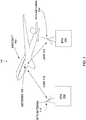
- FIGURE 1 illustrates a diagram of an example of an air-to-ground telecommunications system.
- a system 100 includes an aircraft 102 and multiple base transmission stations (BTS) 104-106. Although only the aircraft 102, the BTS 104 and the BTS 106 are shown for clarity, any number of aircraft and BTSs can be implemented within the scope of the present disclosure.
- BTS base transmission stations
- the aircraft 102 has an antenna 108 that is used for communication with one or more of the BTS 104 and the BTS 106 via a communication link 110 and/or a communication link 112 via a BTS antenna 114 and/or a BTS antenna 116.
- the aircraft 102 will enter and leave the service area for BTS 104 and/or BTS 106, as well as any other BTSs that are in a geographically proximate area.
- terrestrial cellular systems adapted for ATG service use a wide beam width (e.g., the BTS antenna 114 and/or the BTS antenna 116) to service the aircraft 102 via the antenna 108.
- the wide beam width in used in an attempt to provide voice and low-speed data services to cellular telephones or other mobile devices (not shown) that are on board of the aircraft 102.
- Such an approach typically does not have sufficient bandwidth or power to properly maintain the communication link 110 or the communication link 112 to service the aircraft 102 or other aircraft that are in the geographic service area for the BTS 104 and/or the BTS 106.
- aspects of the present disclosure provide support for the communication link 110 and the communication link 112 by higher frequencies to increase the bandwidth provided to the aircraft 102 from the BTS 104 and/or the BTS 106.
- the higher frequencies enable a higher data rate service to the aircraft 102, as well as other aircraft in the geographic service areas of the BTS 104 and/or the BTS 106.
- FIGURE 2 illustrates a base station transmitting antenna in accordance with one or more aspects of the present disclosure.
- An antenna 200 (illustrated as the BTS antenna 114 and/or the BTS antenna 116 in FIGURE 1 ) can be a steerable beam antenna, implemented as a phased array antenna having multiple antenna elements 202-208.
- Other steerable beam antennas, such as tracking antennas, are envisioned as within the scope of the present disclosure.
- the system 100 of the present disclosure may use microwave spectrum currently used by very small aperture terminal (VSAT) uplinks, which is typically in the Ku-band of frequencies at approximately 12-14 GHz, although can also be in other frequency ranges and bands without departing from the scope of the present disclosure.
- VSAT very small aperture terminal
- aspects of the present disclosure control the antenna patterns of the BTS antenna 114 and the BTS antenna 116, as well as the antenna pattern of the antenna 108, to reduce interference between the system 100 and VSAT systems.
- the BTS antenna 114 and/or the BTS antenna 116 use very narrow transmission beams, sometimes called “pencil" beams.
- Pencil beams may have main power lobes of the beam pattern that are on the order of 1 degree by 2 degrees for supporting spatial multiplexing gain where the VSAT spectrum is reused for multiple aircraft from each BTS 104-106.
- This spatial multiplexing utilizes these very well defined beams by reducing interference, also referred to as "bleed over,” from one beam to any other beam within the system 100.
- the BTS uses these beams to transmit communication signals to aircraft and to receive communication signals from aircraft.
- each of the aircraft 102 is illuminated with a narrow pencil beam formed by the antenna elements 202-208. These beams are used to establish the communication link 110 (or the communication link 112), and these links are maintained by an antenna controller 210.
- the antenna controller 210 controls the phase and amplitude coefficients of signals that drive each of the antenna elements 202-208 to form and manipulate the beams used for the communication link 110.
- the processor 212 is coupled to antenna controller 210, the transmitter 222, and the receiver 220 at the BTS 104-106.
- the processor 212 may direct the formation of many beams over the communication link 110 depending on the amplitude and phase coefficients for a given signal to be transmitted or a given signal being received at the BTS 104 and/or the BTS 106.
- the signals contained in those beams include reference signals, which are known by both the transmitter and the receiver.
- the reference signals are intended to enable measurement of the signal. These reference signals are also known as pilots or pilot signals.
- the aircraft 102 operates similarly, in that the communication link signals are sensed at the antenna 108 and received at the aircraft receiver 216. These signals are processed by the processor 212, which may be a similar or different processor than the processor 212 at the BTS 104 and/or the BTS 106, and then transmitted in the aircraft 102 by the transmitter 213.
- the internal antenna 214 transmits these signals to a user equipment 218 (UE), such as cellular telephones and PDA devices, which then transmit back to the internal antenna 214.
- UE user equipment 218
- These signals are then received by the transmitter 213 and processed by the processor 212, and then retransmitted by the transmitter 213 through the antenna 108 back to the BTS 104 and/or the BTS 106.
- the antenna 200 creates pencil beams through the use of the antenna 200 (e.g., a phased array) made up of multiple antenna elements 202-208 that are energized in particular phase and amplitude configurations to follow the aircraft 102 as it moves.
- Mechanical stress, thermal and local scattering effects affect the communication link 110 and the communication link 112. These effects also distort the beam pattern of the antenna 200 which reduces the performance of the system 100 by increasing the power in the side lobes of the antenna beam created by the antenna 200. Because the beam from the antenna 200 is only fully formed and measurable at a considerable distance from the antenna 200, typically several meters from the antenna 200 itself because of the high gain of the antenna 200 beam, sampling the beam close to the antenna (e.g., in the near field) is problematic.
- atmospheric conditions between the BTS 104-106 and the antenna 108 of the aircraft 102 may affect the beam, causing it to distort or diverge from the determined path, which affects the performance of the communication link 110.
- the distortion or divergence effects may include beam squint, beam size distortion, or other effects, any of which reduces the bandwidth available for data/voice transmission between the BTS 104-106 and the antenna 108.
- the antenna 200 can compensate for these effects by adjusting the phase and amplitude of the drive to each of the antenna elements 202-208, but only when there is some ability to determine the shape of the beam formed by antenna 200 at an appropriate distance from the antenna.
- an apparatus of the present disclosure includes a means for receiving position locations from each of the plurality of aircraft.
- the apparatus further includes a means for receiving an attitude of each of the plurality of aircraft, and a means for receiving measurements of pilot signals from each of the plurality of aircraft.
- the apparatus also includes a means for adjusting an amplitude and a phase of a signal driving at least one antenna transmit element to refine the beam pattern.
- the means for receiving an attitude of each of the plurality of aircraft and the means for receiving measurements may be the receiver 220, configured to perform the functions recited by each of the receiving means.
- the means for adjusting may be the antenna controller 210, configured to perform the functions of the adjusting means.
- the aforementioned means may be a device or other apparatus configured to perform the functions recited by the aforementioned means.
- an apparatus of the present disclosure includes means for receiving communication signals containing pilot signals from a base station transmitter.
- the apparatus further includes means for measuring the pilot signals at the first aircraft, and means for transmitting pilot signal measurement reports to the base station.
- the apparatus further includes means for adjusting an amplitude and a phase of a signal driving at least one antenna transmit element in the base station transmitter.
- the means for receiving communications signals may be the receiver 216, configured to perform the functions recited by the receiving means.
- the means for measuring may be the processor 212, configured to perform the functions of the measuring means.
- the means for transmitting may be the transmitter 213, configured to perform the functions of the transmitting means.
- the means for adjusting may be the antenna controller 210, configured to perform the functions of the adjusting means.
- the aforementioned means may be a device or other apparatus configured to perform the functions recited by the aforementioned means.
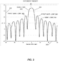
- FIGURE 3 illustrates an azimuth antenna pattern that may be deployed in an air-to-ground broadband communications system in accordance with aspects of the present disclosure.
- the precise adjustment of the amplitude and phase coefficients is not critical if the system only employs one beam.
- the adjustment of the coefficients becomes more important. This precise adjustment of coefficients is known as calibration of the phased array.
- the horizontal axis 300 indicates the angle in the horizontal plane
- the vertical axis 302 indicates the signal amplitude 304 in that direction.
- the intended target e.g., aircraft 102 or, alternatively, the BTS 104 and/or the BTS 106
- the intended target is in the center of the chart with the angle of 0 degrees, which is also referred to as the antenna bore sight.
- the phased array coefficients for the antenna are calibrated to the proper values.
- the signal amplitude peak gain is 35 dB at bore sight.
- the antenna provides 35 dB of gain to the signal entering the antenna 200.
- the first side lobes 308 of the antenna 200 appear at approximately plus and minus 15 degrees away from the main beam and have a gain of 22 dB. This means the signal transmitted from this antenna will be 13 dB weaker at the angle of the first side lobes 308 than at the angle of the bore sight. That is, areas that are ten degrees away from the intended target (e.g., other aircraft and/or other BTS) receive a signal that is 13 dB lower in power than the intended target receives if the antenna 200 is pointed correctly. Additional side lobes 310 are spaced at intervals of angles farther off the bore sight.
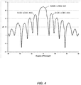
- FIGURE 4 illustrates an azimuth antenna pattern that may be deployed in an air-to-ground broadband communications system.
- FIGURE 4 illustrates the antenna 200 configured as a phased array with random errors of plus and minus 10 degrees in phase and plus and minus 15 percent in amplitude. At the frequency of interest these are fairly small errors that cannot be minimized without frequent adjustment as the temperature varies and mechanical stresses on the antenna structure change, such as from strong winds.
- the main lobe 400 has only very minor degradation with respect to the main lobe 306 of FIGURE 3 , with the peak gain of the main lobe 400 dropping about 1 dB.
- the side lobes 402 and 404 have increased dramatically from 13 dB below the peak gain to only 9 dB below. This shows that the power being transmitted to locations other than the intended target has increased by over 50%, which decreases the power used for data transmission and increases the power that bleeds over creating interference with other beams and other targets.
- FIGURE 5 illustrates a comparison between the antenna patterns of FIGURES 3 and 4 .
- a pattern 500 (solid line) is shown from FIGURE 3
- pattern 502 (dashed line) is shown from FIGURE 4 .
- FIGURE 6 illustrates example antenna patterns where multiple antennas are simultaneously communicating with an antenna.
- the beam patterns 600-604 illustrate the antenna patterns of three closely spaced targets (e.g., the aircraft 102) that can be simultaneously communicating with the BTS 104 and/or the BTS 106.
- the beam patterns 600-604 indicate that three separate beams are used to provide spatial multiplexing, such that the main lobes of each of the beam patterns 600-604 are pointed in different directions, allowing each target (e.g., the aircraft 102) to discriminate between the patterns.
- Such spatial discrimination allows for frequency channel reuse from a given one of the BTS 104 and/or the BTS 106.
- three beam patterns 600-604 are shown, a larger or smaller number of the beam patterns 600-604 can be used within the scope of the present disclosure.
- the side lobes of each of the beam patterns 600-604 allow signal to spill over into the adjacent beams. As interference between the side lobes and main lobe for each of the beam patterns 600-604 increases, the difference in power between the side lobes and the main lobe of each of the beam patterns 600-604 becomes more important.
- FIGURE 6 there is a 13 dB difference between the main lobe peak power and the side lobe power. As more beams are used, additional side lobes spill signals into adjacent beams. As a result, the additional beams further reduce the signal-to-interference ratio of the system. As the beam patterns 600-604 are limited in terms of the difference between main lobe and side lobe power ratios, any degradation of the inherent power levels severely impacts performance of the system 100.
- FIGURE 7 illustrates an example beam configuration of FIGURE 6 with coefficient and phase errors introduced.
- FIGURE 7 illustrates the beam patterns 700-704, where random errors of plus and minus 10 degrees in phase and plus and minus 15 percent in amplitude are introduced into the coefficients used to form the antenna beams.
- the peak gain to interfering side lobes ratio is reduced from 13 dB to 8 dB, more than a doubling of adjacent beam interference. Such degradation introduces errors in data transfer, reduces data throughput, and increases the possibility of lost communications channels in the system 100.
- the aircraft 102 that are in communication with the BTS 104 and/or the BTS 106 via the communication link 110 and/or the communication link 112 are typically in well-known positions and move across the geographic regions serviced by the BTS 104 and/or the BTS 106.
- the aircraft receiver 216 either via processor 212 or other measurement device at the aircraft 102, can measure the signal that is transmitted by the BTS antenna 114 and the BTS antenna 116 (e.g., the antenna 200), and send these measurements back to the BTS 104 and the BTS 106 via the communication link 110.
- the aircraft 102 can send precise aircraft position and attitude information 224, which may include the time of the signal strength measurements and/or the time of the position/attitude measurements, via the communication link 110.
- the BTS 104 and the BTS 106 can then use the signal and the aircraft position and attitude information 224 from any one, any plurality, or all available aircraft to calculate the transmit beam patterns for the antenna 200 and make any amplitude and phase adjustments via the antenna controller 210 or other system for correcting the uplink beams.
- the BTS 104 and/or the BTS 106 can also use the downlink signal of the communication link 110 (e.g., the transmission from the transmitter 213 and antenna 108) and the aircraft position and attitude information 224 to help calibrate the BTS 104 and the BTS 106 receiver antenna arrays.
- the base station transmit and receive antennas may be the same physical array of the antenna elements 202-208, the phase and amplitude parameters used to form the transmit beam may be different than the phase and amplitude parameters used to form the receive beam of the communication link 110.
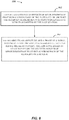
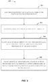
- FIGURE 10 illustrates a method 1000 of refining a beam pattern of an antenna beam of a base station antenna in accordance with another aspect of the disclosure.
- Block 1002 illustrates receiving communication signals containing pilots at a first aircraft in the plurality of aircraft from the base station.
- Block 1004 illustrates measuring the pilots at the first aircraft.
- Block 1006 illustrates transmitting the pilot measurement reports from the first aircraft to the base station.
- Block 1008 illustrates receiving further communication signals with reduced interference at the at least one aircraft in the plurality of aircraft resulting from the base station adjusting an amplitude and a phase of a signal driving at least one antenna transmit element to refine the beam pattern, the adjusting based at least in part on the reports of measurements of pilot signals transmitted from the first aircraft.
- the processor 212 may be coupled to or include computer-readable medium 250.
- the processor 212 is responsible for general processing, including the execution of software stored on the computer-readable medium 250.
- the software when executed by the processor 212, causes various functions to be performed as described for any particular apparatus.
- the computer-readable medium 250 may also be used for storing data that is manipulated by the processor 212 when executing software.
- processor 212 having been described in connection with various apparatuses and methods, may be implemented using electronic hardware, computer software, or any combination thereof. Whether such processors are implemented as hardware or software will depend upon the particular application and overall design constraints imposed on the system.
- a processor, any portion of a processor, or any combination of processors presented in this disclosure may be implemented with a microprocessor, microcontroller, digital signal processor (DSP), a field-programmable gate array (FPGA), a programmable logic device (PLD), a state machine, gated logic, discrete hardware circuits, and other suitable processing components configured to perform the various functions described throughout this disclosure.
- DSP digital signal processor
- FPGA field-programmable gate array
- PLD programmable logic device
- state machine gated logic, discrete hardware circuits, and other suitable processing components configured to perform the various functions described throughout this disclosure.
- the functionality of a processor, any portion of a processor, or any combination of processors presented in this disclosure may be implemented with software being executed by a microprocessor, microcontrol
- Software shall be construed broadly to mean instructions, instruction sets, code, code segments, program code, programs, subprograms, software modules, applications, software applications, software packages, routines, subroutines, objects, executables, threads of execution, procedures, functions, etc., whether referred to as software, firmware, middleware, microcode, hardware description language, or otherwise.
- the software may reside on a computer-readable medium.
- a computer-readable medium may include, by way of example, memory such as a magnetic storage device (e.g., hard disk, floppy disk, magnetic strip), an optical disk (e.g., compact disc (CD), digital versatile disc (DVD)), a smart card, a flash memory device (e.g., card, stick, key drive), random access memory (RAM), read only memory (ROM), programmable ROM (PROM), erasable PROM (EPROM), electrically erasable PROM (EEPROM), a register, or a removable disk.
- memory is shown separate from the processors in the various aspects presented throughout this disclosure, the memory may be internal to the processors (e.g., cache or register).
- the computer-readable medium 250 may be embodied in a computer-program product.
- a computer-program product may include a computer-readable medium in packaging materials.
Landscapes
- Engineering & Computer Science (AREA)
- Computer Networks & Wireless Communication (AREA)
- Signal Processing (AREA)
- Physics & Mathematics (AREA)
- Astronomy & Astrophysics (AREA)
- Aviation & Aerospace Engineering (AREA)
- General Physics & Mathematics (AREA)
- Radio Transmission System (AREA)
- Mobile Radio Communication Systems (AREA)
- Variable-Direction Aerials And Aerial Arrays (AREA)
- Details Of Aerials (AREA)
Applications Claiming Priority (2)
| Application Number | Priority Date | Filing Date | Title |
|---|---|---|---|
| US13/740,248 US10470095B2 (en) | 2013-01-13 | 2013-01-13 | Method for air-to-ground data link antenna self calibration |
| PCT/US2014/011121 WO2014110427A1 (en) | 2013-01-13 | 2014-01-10 | Method for air-to-ground data link antenna self calibration |
Publications (2)
| Publication Number | Publication Date |
|---|---|
| EP2943996A1 EP2943996A1 (en) | 2015-11-18 |
| EP2943996B1 true EP2943996B1 (en) | 2019-11-27 |
Family
ID=50030525
Family Applications (1)
| Application Number | Title | Priority Date | Filing Date |
|---|---|---|---|
| EP14702147.1A Active EP2943996B1 (en) | 2013-01-13 | 2014-01-10 | Method for air-to-ground data link antenna self calibration |
Country Status (5)
| Country | Link |
|---|---|
| US (1) | US10470095B2 (enExample) |
| EP (1) | EP2943996B1 (enExample) |
| JP (3) | JP2016522997A (enExample) |
| CN (1) | CN104919651B (enExample) |
| WO (1) | WO2014110427A1 (enExample) |
Families Citing this family (27)
| Publication number | Priority date | Publication date | Assignee | Title |
|---|---|---|---|---|
| DE102014210204A1 (de) * | 2014-05-28 | 2015-12-03 | Lufthansa Systems Gmbh & Co. Kg | Vorrichtung und Verfahren zur Luft-Boden-Kommunikation von Luftfahrzeugen |
| US9735862B2 (en) * | 2014-09-15 | 2017-08-15 | Verizon Patent And Licensing Inc. | System and method for providing cellular signals to mobile device users travelling by air |
| US9491635B2 (en) | 2015-01-13 | 2016-11-08 | Smartsky Networks LLC | Architecture for simultaneous spectrum usage by air-to-ground and terrestrial networks |
| US10219166B2 (en) * | 2015-04-30 | 2019-02-26 | Mist Systems, Inc. | Methods and apparatus for generating, transmitting and/or using beacons |
| US9363784B1 (en) | 2015-04-30 | 2016-06-07 | Mist Systems Inc. | Methods and apparatus relating to the use of real and/or virtual beacons |
| WO2016206007A1 (zh) * | 2015-06-24 | 2016-12-29 | 华为技术有限公司 | 一种波束调整方法及装置 |
| US9954598B2 (en) | 2015-11-03 | 2018-04-24 | Telefonaktiebolaget Lm Ericsson (Publ) | High capacity cellular communications system coverage of airborne mobile communications equipment |
| US9813969B2 (en) | 2015-11-03 | 2017-11-07 | Telefonaktiebolaget Lm Ericsson (Publ) | In-flight cellular communications system coverage of mobile communications equipment located in aircraft |
| US10111152B2 (en) | 2015-12-09 | 2018-10-23 | Telefonaktiebolaget Lm Ericsson (Publ) | Cell selection for airborne mobile cellular communications equipment |
| US10034181B1 (en) | 2016-06-29 | 2018-07-24 | Sprint Communications Company L.P. | Dynamic mitigation of tropospheric ducting and refraction based interference events with dynamic antenna tilt |
| US9954600B2 (en) * | 2016-07-05 | 2018-04-24 | Gogo Llc | Servicing cell selection in air to ground communication systems |
| WO2018078004A1 (en) | 2016-10-28 | 2018-05-03 | Telefonaktiebolaget Lm Ericsson (Publ) | Wireless communication links between airborne and ground-based communications equipment |
| US10277269B2 (en) | 2016-12-09 | 2019-04-30 | The Boeing Company | Phased array beam tracking using beam gain coding |
| CN108271118B (zh) | 2016-12-30 | 2020-09-25 | 华为技术有限公司 | 高空通信系统、方法及装置 |
| SE1751148A1 (en) * | 2017-09-18 | 2019-03-19 | Icomera Ab | Wireless communication system for aircrafts |
| CN111133688B (zh) * | 2017-09-21 | 2022-05-03 | 智慧天空网络有限公司 | 被动收集空对地网络参数用于网络规划和控制 |
| CN116095734A (zh) | 2017-09-21 | 2023-05-09 | 空五股份有限公司 | 用于通信的方法、装置和计算机可读存储介质 |
| EP3576472B1 (en) * | 2017-09-27 | 2021-06-16 | CloudMinds (Shanghai) Robotics Co., Ltd. | Resource allocation method and apparatus, network device, and storage medium |
| AU2018388483B2 (en) * | 2017-12-19 | 2023-03-09 | Smartsky Networks LLC | Interference mitigation based on antenna system phase distribution |
| CN111869123B (zh) * | 2018-04-05 | 2022-08-09 | 华为技术有限公司 | 用于高效波束管理的通信设备 |
| US11757183B2 (en) | 2018-08-31 | 2023-09-12 | Telefonaktiebolaget Lm Ericsson (Publ) | Efficient antenna calibration for large antenna arrays |
| US10630395B1 (en) * | 2018-12-28 | 2020-04-21 | Sprint Communications Company L.P. | Automated mitigation of atmospheric-based interference events |
| WO2020244783A1 (en) | 2019-06-07 | 2020-12-10 | Telefonaktiebolaget Lm Ericsson (Publ) | Calibration for antenna elements of a multi-antenna structure |
| CN110515038B (zh) * | 2019-08-09 | 2023-03-28 | 达洛科技(广州)有限公司 | 一种基于无人机-阵列的自适应无源定位装置及实现方法 |
| JP2023552381A (ja) * | 2020-12-02 | 2023-12-15 | テクトロニクス・インコーポレイテッド | フェーズド・アレイ無線試験 |
| WO2023123042A1 (en) * | 2021-12-29 | 2023-07-06 | Telefonaktiebolaget Lm Ericsson (Publ) | Method and apparatus for performing a beamformed test signaling |
| US20250087875A1 (en) * | 2023-09-11 | 2025-03-13 | L3Harris Technologies, Inc. | Window mountable direction-finding antenna arrays |
Family Cites Families (27)
| Publication number | Priority date | Publication date | Assignee | Title |
|---|---|---|---|---|
| US5557282A (en) * | 1988-10-11 | 1996-09-17 | Itt Corporation | Height finding antenna apparatus and method of operation |
| US5027124A (en) | 1989-03-17 | 1991-06-25 | The Boeing Company | System for maintaining polarization and signal-to-noise levels in received frequency reuse communications |
| US8145208B2 (en) | 2006-10-31 | 2012-03-27 | Gogo Llc | Air-to-ground cellular communication network terrestrial base station having multi-dimensional sectors with alternating radio frequency polarizations |
| US8914022B2 (en) | 1992-03-06 | 2014-12-16 | Gogo Llc | System for providing high speed communications service in an airborne wireless cellular network |
| US6018659A (en) | 1996-10-17 | 2000-01-25 | The Boeing Company | Airborne broadband communication network |
| US5781845A (en) * | 1996-12-03 | 1998-07-14 | The Aerospace Corporation | Adaptive transmitting antenna |
| US6100843A (en) | 1998-09-21 | 2000-08-08 | Tantivy Communications Inc. | Adaptive antenna for use in same frequency networks |
| EP1232661B1 (en) | 1999-09-13 | 2010-09-29 | Torsal Technology Group Ltd. LLC | Communications system load control methods and apparatus |
| GB2362073B (en) * | 2000-05-03 | 2003-12-17 | Siemens Ag | Equaliser and method of state reduction therefor |
| AU2001290536A1 (en) | 2000-08-18 | 2002-03-04 | Phasenet Wireless Communications Corporation | Airborne cellular communications system |
| KR20040008233A (ko) | 2001-06-29 | 2004-01-28 | 모토로라 인코포레이티드 | 항공 셀룰러 시스템을 위한 지원자 핸드오프 목록 |
| US6759978B2 (en) * | 2002-03-21 | 2004-07-06 | Ball Aerospace & Technologies Corp. | Cross-link antenna system |
| US8213994B2 (en) * | 2002-08-07 | 2012-07-03 | Interdigital Technology Corporation | Mobile communications system and method for providing common channel coverage using beamforming antennas |
| US7813440B2 (en) * | 2003-01-31 | 2010-10-12 | Ntt Docomo, Inc. | Multiple-output multiple-input (MIMO) communication system, MIMO receiver and MIMO receiving method |
| US7113779B1 (en) | 2004-01-08 | 2006-09-26 | Iwao Fujisaki | Carrier |
| US20060229076A1 (en) | 2005-04-08 | 2006-10-12 | Monk Anthony D | Soft handoff method and apparatus for mobile vehicles using directional antennas |
| US7920860B2 (en) | 2006-10-31 | 2011-04-05 | Aircell Llc | System for managing the multiple air-to-ground communications links originating from each aircraft in an air-to-ground cellular communication network |
| US8671432B2 (en) * | 2007-10-16 | 2014-03-11 | Livetv, Llc | Aircraft in-flight entertainment system having a dual-beam antenna and associated methods |
| EP1983787B1 (en) * | 2007-04-19 | 2012-11-28 | Nokia Siemens Networks Oy | Transmission and distribution of position- and/or network-related information from access networks |
| JP2009081696A (ja) | 2007-09-26 | 2009-04-16 | Toshiba Corp | 航空機通信システムとそのアンテナ指向制御方法 |
| CN101884175B (zh) * | 2007-12-05 | 2013-04-17 | 富士通株式会社 | 发送装置、发送控制方法以及通信装置 |
| US8508409B2 (en) * | 2008-11-04 | 2013-08-13 | Nec Corporation | Control method of wireless communication system, wireless communication system, adjustment method of array weight vector, and wireless communication device |
| US7969358B2 (en) * | 2008-11-19 | 2011-06-28 | Harris Corporation | Compensation of beamforming errors in a communications system having widely spaced antenna elements |
| WO2010143353A1 (ja) * | 2009-06-08 | 2010-12-16 | 日本電気株式会社 | 無線通信システムの制御方法、無線通信システム、無線通信装置、及びアレイ重みベクトルの調整方法 |
| US8614643B2 (en) | 2009-08-06 | 2013-12-24 | Truepath Holdings Llc | System and methods for antenna optimization for wireless broadband communication |
| US8891647B2 (en) | 2009-10-30 | 2014-11-18 | Futurewei Technologies, Inc. | System and method for user specific antenna down tilt in wireless cellular networks |
| US8676192B2 (en) * | 2011-02-09 | 2014-03-18 | Qualcomm Incorporated | High data rate aircraft to ground communication antenna system |
-
2013
- 2013-01-13 US US13/740,248 patent/US10470095B2/en active Active
-
2014
- 2014-01-10 CN CN201480004553.2A patent/CN104919651B/zh active Active
- 2014-01-10 EP EP14702147.1A patent/EP2943996B1/en active Active
- 2014-01-10 JP JP2015552827A patent/JP2016522997A/ja active Pending
- 2014-01-10 WO PCT/US2014/011121 patent/WO2014110427A1/en not_active Ceased
-
2018
- 2018-12-21 JP JP2018239910A patent/JP7187295B2/ja active Active
-
2021
- 2021-11-22 JP JP2021189421A patent/JP2022043046A/ja active Pending
Non-Patent Citations (1)
| Title |
|---|
| None * |
Also Published As
| Publication number | Publication date |
|---|---|
| US10470095B2 (en) | 2019-11-05 |
| JP2019075804A (ja) | 2019-05-16 |
| EP2943996A1 (en) | 2015-11-18 |
| CN104919651B (zh) | 2018-02-16 |
| WO2014110427A1 (en) | 2014-07-17 |
| CN104919651A (zh) | 2015-09-16 |
| JP2022043046A (ja) | 2022-03-15 |
| JP2016522997A (ja) | 2016-08-04 |
| US20160212669A1 (en) | 2016-07-21 |
| JP7187295B2 (ja) | 2022-12-12 |
Similar Documents
| Publication | Publication Date | Title |
|---|---|---|
| EP2943996B1 (en) | Method for air-to-ground data link antenna self calibration | |
| JP2016522997A5 (enExample) | ||
| US10103428B2 (en) | Low cost high performance aircraft antenna for advanced ground to air internet system | |
| KR102360451B1 (ko) | 가속화된 위성 획득 구조 | |
| US10547373B2 (en) | Wireless communication links between airborne and ground-based communications equipment | |
| KR101717617B1 (ko) | 공대지 시스템들에 대한 간섭 완화 기법들 | |
| KR101825122B1 (ko) | 하이 데이터 레이트 항공기 대 지상 통신 안테나 시스템 | |
| US9293820B2 (en) | Compensating for a non-ideal surface of a reflector in a satellite communication system | |
| GB2536017A (en) | Generation and use of similar multiple beams | |
| GB2536018A (en) | Increasing data transfer rates | |
| EP2434577A1 (en) | Antenna arrangement for direct air-to-ground communication | |
| KR102415222B1 (ko) | 저궤도 위성을 이용한 위성신호 송수신 시스템 및 그 위성신호 송수신 방법 | |
| US9941600B2 (en) | Ultra low profile conformal antenna system | |
| US11223416B2 (en) | Communication system for aircrafts with altitude based antenna type selection | |
| US20250132814A1 (en) | Terminal with interference avoidance between satellite systems using common spectrum |
Legal Events
| Date | Code | Title | Description |
|---|---|---|---|
| PUAI | Public reference made under article 153(3) epc to a published international application that has entered the european phase |
Free format text: ORIGINAL CODE: 0009012 |
|
| 17P | Request for examination filed |
Effective date: 20150730 |
|
| AK | Designated contracting states |
Kind code of ref document: A1 Designated state(s): AL AT BE BG CH CY CZ DE DK EE ES FI FR GB GR HR HU IE IS IT LI LT LU LV MC MK MT NL NO PL PT RO RS SE SI SK SM TR |
|
| AX | Request for extension of the european patent |
Extension state: BA ME |
|
| DAX | Request for extension of the european patent (deleted) | ||
| STAA | Information on the status of an ep patent application or granted ep patent |
Free format text: STATUS: EXAMINATION IS IN PROGRESS |
|
| 17Q | First examination report despatched |
Effective date: 20180621 |
|
| GRAP | Despatch of communication of intention to grant a patent |
Free format text: ORIGINAL CODE: EPIDOSNIGR1 |
|
| STAA | Information on the status of an ep patent application or granted ep patent |
Free format text: STATUS: GRANT OF PATENT IS INTENDED |
|
| INTG | Intention to grant announced |
Effective date: 20190628 |
|
| GRAS | Grant fee paid |
Free format text: ORIGINAL CODE: EPIDOSNIGR3 |
|
| GRAA | (expected) grant |
Free format text: ORIGINAL CODE: 0009210 |
|
| STAA | Information on the status of an ep patent application or granted ep patent |
Free format text: STATUS: THE PATENT HAS BEEN GRANTED |
|
| AK | Designated contracting states |
Kind code of ref document: B1 Designated state(s): AL AT BE BG CH CY CZ DE DK EE ES FI FR GB GR HR HU IE IS IT LI LT LU LV MC MK MT NL NO PL PT RO RS SE SI SK SM TR |
|
| REG | Reference to a national code |
Ref country code: GB Ref legal event code: FG4D |
|
| REG | Reference to a national code |
Ref country code: CH Ref legal event code: EP |
|
| REG | Reference to a national code |
Ref country code: AT Ref legal event code: REF Ref document number: 1207760 Country of ref document: AT Kind code of ref document: T Effective date: 20191215 |
|
| REG | Reference to a national code |
Ref country code: DE Ref legal event code: R096 Ref document number: 602014057421 Country of ref document: DE |
|
| REG | Reference to a national code |
Ref country code: IE Ref legal event code: FG4D |
|
| REG | Reference to a national code |
Ref country code: NL Ref legal event code: MP Effective date: 20191127 |
|
| REG | Reference to a national code |
Ref country code: LT Ref legal event code: MG4D |
|
| PG25 | Lapsed in a contracting state [announced via postgrant information from national office to epo] |
Ref country code: NO Free format text: LAPSE BECAUSE OF FAILURE TO SUBMIT A TRANSLATION OF THE DESCRIPTION OR TO PAY THE FEE WITHIN THE PRESCRIBED TIME-LIMIT Effective date: 20200227 Ref country code: LT Free format text: LAPSE BECAUSE OF FAILURE TO SUBMIT A TRANSLATION OF THE DESCRIPTION OR TO PAY THE FEE WITHIN THE PRESCRIBED TIME-LIMIT Effective date: 20191127 Ref country code: FI Free format text: LAPSE BECAUSE OF FAILURE TO SUBMIT A TRANSLATION OF THE DESCRIPTION OR TO PAY THE FEE WITHIN THE PRESCRIBED TIME-LIMIT Effective date: 20191127 Ref country code: BG Free format text: LAPSE BECAUSE OF FAILURE TO SUBMIT A TRANSLATION OF THE DESCRIPTION OR TO PAY THE FEE WITHIN THE PRESCRIBED TIME-LIMIT Effective date: 20200227 Ref country code: NL Free format text: LAPSE BECAUSE OF FAILURE TO SUBMIT A TRANSLATION OF THE DESCRIPTION OR TO PAY THE FEE WITHIN THE PRESCRIBED TIME-LIMIT Effective date: 20191127 Ref country code: SE Free format text: LAPSE BECAUSE OF FAILURE TO SUBMIT A TRANSLATION OF THE DESCRIPTION OR TO PAY THE FEE WITHIN THE PRESCRIBED TIME-LIMIT Effective date: 20191127 Ref country code: LV Free format text: LAPSE BECAUSE OF FAILURE TO SUBMIT A TRANSLATION OF THE DESCRIPTION OR TO PAY THE FEE WITHIN THE PRESCRIBED TIME-LIMIT Effective date: 20191127 Ref country code: GR Free format text: LAPSE BECAUSE OF FAILURE TO SUBMIT A TRANSLATION OF THE DESCRIPTION OR TO PAY THE FEE WITHIN THE PRESCRIBED TIME-LIMIT Effective date: 20200228 |
|
| PG25 | Lapsed in a contracting state [announced via postgrant information from national office to epo] |
Ref country code: HR Free format text: LAPSE BECAUSE OF FAILURE TO SUBMIT A TRANSLATION OF THE DESCRIPTION OR TO PAY THE FEE WITHIN THE PRESCRIBED TIME-LIMIT Effective date: 20191127 Ref country code: IS Free format text: LAPSE BECAUSE OF FAILURE TO SUBMIT A TRANSLATION OF THE DESCRIPTION OR TO PAY THE FEE WITHIN THE PRESCRIBED TIME-LIMIT Effective date: 20200327 Ref country code: RS Free format text: LAPSE BECAUSE OF FAILURE TO SUBMIT A TRANSLATION OF THE DESCRIPTION OR TO PAY THE FEE WITHIN THE PRESCRIBED TIME-LIMIT Effective date: 20191127 |
|
| PG25 | Lapsed in a contracting state [announced via postgrant information from national office to epo] |
Ref country code: AL Free format text: LAPSE BECAUSE OF FAILURE TO SUBMIT A TRANSLATION OF THE DESCRIPTION OR TO PAY THE FEE WITHIN THE PRESCRIBED TIME-LIMIT Effective date: 20191127 |
|
| PG25 | Lapsed in a contracting state [announced via postgrant information from national office to epo] |
Ref country code: CZ Free format text: LAPSE BECAUSE OF FAILURE TO SUBMIT A TRANSLATION OF THE DESCRIPTION OR TO PAY THE FEE WITHIN THE PRESCRIBED TIME-LIMIT Effective date: 20191127 Ref country code: RO Free format text: LAPSE BECAUSE OF FAILURE TO SUBMIT A TRANSLATION OF THE DESCRIPTION OR TO PAY THE FEE WITHIN THE PRESCRIBED TIME-LIMIT Effective date: 20191127 Ref country code: ES Free format text: LAPSE BECAUSE OF FAILURE TO SUBMIT A TRANSLATION OF THE DESCRIPTION OR TO PAY THE FEE WITHIN THE PRESCRIBED TIME-LIMIT Effective date: 20191127 Ref country code: EE Free format text: LAPSE BECAUSE OF FAILURE TO SUBMIT A TRANSLATION OF THE DESCRIPTION OR TO PAY THE FEE WITHIN THE PRESCRIBED TIME-LIMIT Effective date: 20191127 Ref country code: PT Free format text: LAPSE BECAUSE OF FAILURE TO SUBMIT A TRANSLATION OF THE DESCRIPTION OR TO PAY THE FEE WITHIN THE PRESCRIBED TIME-LIMIT Effective date: 20200419 Ref country code: DK Free format text: LAPSE BECAUSE OF FAILURE TO SUBMIT A TRANSLATION OF THE DESCRIPTION OR TO PAY THE FEE WITHIN THE PRESCRIBED TIME-LIMIT Effective date: 20191127 |
|
| REG | Reference to a national code |
Ref country code: DE Ref legal event code: R097 Ref document number: 602014057421 Country of ref document: DE |
|
| PG25 | Lapsed in a contracting state [announced via postgrant information from national office to epo] |
Ref country code: MC Free format text: LAPSE BECAUSE OF FAILURE TO SUBMIT A TRANSLATION OF THE DESCRIPTION OR TO PAY THE FEE WITHIN THE PRESCRIBED TIME-LIMIT Effective date: 20191127 Ref country code: SM Free format text: LAPSE BECAUSE OF FAILURE TO SUBMIT A TRANSLATION OF THE DESCRIPTION OR TO PAY THE FEE WITHIN THE PRESCRIBED TIME-LIMIT Effective date: 20191127 Ref country code: SK Free format text: LAPSE BECAUSE OF FAILURE TO SUBMIT A TRANSLATION OF THE DESCRIPTION OR TO PAY THE FEE WITHIN THE PRESCRIBED TIME-LIMIT Effective date: 20191127 |
|
| REG | Reference to a national code |
Ref country code: CH Ref legal event code: PL |
|
| REG | Reference to a national code |
Ref country code: AT Ref legal event code: MK05 Ref document number: 1207760 Country of ref document: AT Kind code of ref document: T Effective date: 20191127 |
|
| PLBE | No opposition filed within time limit |
Free format text: ORIGINAL CODE: 0009261 |
|
| STAA | Information on the status of an ep patent application or granted ep patent |
Free format text: STATUS: NO OPPOSITION FILED WITHIN TIME LIMIT |
|
| REG | Reference to a national code |
Ref country code: BE Ref legal event code: MM Effective date: 20200131 |
|
| PG25 | Lapsed in a contracting state [announced via postgrant information from national office to epo] |
Ref country code: LU Free format text: LAPSE BECAUSE OF NON-PAYMENT OF DUE FEES Effective date: 20200110 |
|
| 26N | No opposition filed |
Effective date: 20200828 |
|
| PG25 | Lapsed in a contracting state [announced via postgrant information from national office to epo] |
Ref country code: AT Free format text: LAPSE BECAUSE OF FAILURE TO SUBMIT A TRANSLATION OF THE DESCRIPTION OR TO PAY THE FEE WITHIN THE PRESCRIBED TIME-LIMIT Effective date: 20191127 Ref country code: PL Free format text: LAPSE BECAUSE OF FAILURE TO SUBMIT A TRANSLATION OF THE DESCRIPTION OR TO PAY THE FEE WITHIN THE PRESCRIBED TIME-LIMIT Effective date: 20191127 Ref country code: LI Free format text: LAPSE BECAUSE OF NON-PAYMENT OF DUE FEES Effective date: 20200131 Ref country code: CH Free format text: LAPSE BECAUSE OF NON-PAYMENT OF DUE FEES Effective date: 20200131 Ref country code: BE Free format text: LAPSE BECAUSE OF NON-PAYMENT OF DUE FEES Effective date: 20200131 Ref country code: SI Free format text: LAPSE BECAUSE OF FAILURE TO SUBMIT A TRANSLATION OF THE DESCRIPTION OR TO PAY THE FEE WITHIN THE PRESCRIBED TIME-LIMIT Effective date: 20191127 |
|
| PG25 | Lapsed in a contracting state [announced via postgrant information from national office to epo] |
Ref country code: IT Free format text: LAPSE BECAUSE OF FAILURE TO SUBMIT A TRANSLATION OF THE DESCRIPTION OR TO PAY THE FEE WITHIN THE PRESCRIBED TIME-LIMIT Effective date: 20191127 Ref country code: IE Free format text: LAPSE BECAUSE OF NON-PAYMENT OF DUE FEES Effective date: 20200110 |
|
| PG25 | Lapsed in a contracting state [announced via postgrant information from national office to epo] |
Ref country code: TR Free format text: LAPSE BECAUSE OF FAILURE TO SUBMIT A TRANSLATION OF THE DESCRIPTION OR TO PAY THE FEE WITHIN THE PRESCRIBED TIME-LIMIT Effective date: 20191127 Ref country code: MT Free format text: LAPSE BECAUSE OF FAILURE TO SUBMIT A TRANSLATION OF THE DESCRIPTION OR TO PAY THE FEE WITHIN THE PRESCRIBED TIME-LIMIT Effective date: 20191127 Ref country code: CY Free format text: LAPSE BECAUSE OF FAILURE TO SUBMIT A TRANSLATION OF THE DESCRIPTION OR TO PAY THE FEE WITHIN THE PRESCRIBED TIME-LIMIT Effective date: 20191127 |
|
| PG25 | Lapsed in a contracting state [announced via postgrant information from national office to epo] |
Ref country code: MK Free format text: LAPSE BECAUSE OF FAILURE TO SUBMIT A TRANSLATION OF THE DESCRIPTION OR TO PAY THE FEE WITHIN THE PRESCRIBED TIME-LIMIT Effective date: 20191127 |
|
| PGFP | Annual fee paid to national office [announced via postgrant information from national office to epo] |
Ref country code: GB Payment date: 20241212 Year of fee payment: 12 |
|
| PGFP | Annual fee paid to national office [announced via postgrant information from national office to epo] |
Ref country code: FR Payment date: 20241216 Year of fee payment: 12 |
|
| PGFP | Annual fee paid to national office [announced via postgrant information from national office to epo] |
Ref country code: DE Payment date: 20241217 Year of fee payment: 12 |