EP2943641B1 - Bohrlochinterventionskabel-verbiegungsbeschränkung für ein starres, aber elastisches stangenförmiges interventionskabel - Google Patents
Bohrlochinterventionskabel-verbiegungsbeschränkung für ein starres, aber elastisches stangenförmiges interventionskabel Download PDFInfo
- Publication number
- EP2943641B1 EP2943641B1 EP13706079.4A EP13706079A EP2943641B1 EP 2943641 B1 EP2943641 B1 EP 2943641B1 EP 13706079 A EP13706079 A EP 13706079A EP 2943641 B1 EP2943641 B1 EP 2943641B1
- Authority
- EP
- European Patent Office
- Prior art keywords
- sleeve
- intervention cable
- spherical
- guide
- sector
- Prior art date
- Legal status (The legal status is an assumption and is not a legal conclusion. Google has not performed a legal analysis and makes no representation as to the accuracy of the status listed.)
- Active
Links
Images




Classifications
-
- E—FIXED CONSTRUCTIONS
- E21—EARTH OR ROCK DRILLING; MINING
- E21B—EARTH OR ROCK DRILLING; OBTAINING OIL, GAS, WATER, SOLUBLE OR MELTABLE MATERIALS OR A SLURRY OF MINERALS FROM WELLS
- E21B19/00—Handling rods, casings, tubes or the like outside the borehole, e.g. in the derrick; Apparatus for feeding the rods or cables
- E21B19/22—Handling reeled pipe or rod units, e.g. flexible drilling pipes
-
- E—FIXED CONSTRUCTIONS
- E21—EARTH OR ROCK DRILLING; MINING
- E21B—EARTH OR ROCK DRILLING; OBTAINING OIL, GAS, WATER, SOLUBLE OR MELTABLE MATERIALS OR A SLURRY OF MINERALS FROM WELLS
- E21B19/00—Handling rods, casings, tubes or the like outside the borehole, e.g. in the derrick; Apparatus for feeding the rods or cables
- E21B19/08—Apparatus for feeding the rods or cables; Apparatus for increasing or decreasing the pressure on the drilling tool; Apparatus for counterbalancing the weight of the rods
- E21B19/084—Apparatus for feeding the rods or cables; Apparatus for increasing or decreasing the pressure on the drilling tool; Apparatus for counterbalancing the weight of the rods with flexible drawing means, e.g. cables
-
- E—FIXED CONSTRUCTIONS
- E21—EARTH OR ROCK DRILLING; MINING
- E21B—EARTH OR ROCK DRILLING; OBTAINING OIL, GAS, WATER, SOLUBLE OR MELTABLE MATERIALS OR A SLURRY OF MINERALS FROM WELLS
- E21B17/00—Drilling rods or pipes; Flexible drill strings; Kellies; Drill collars; Sucker rods; Cables; Casings; Tubings
- E21B17/20—Flexible or articulated drilling pipes, e.g. flexible or articulated rods, pipes or cables
Definitions
- the invention relates to a so-called bending restrictor, i.e. a bending limiter, for a rigid but resiliently pliable intervention cable. More specifically, the invention comprises articulation sleeves which separately are monoaxially articulating and which combined with straight pipe portions form a bending restrictor for such a rigid resilient pliable intervention cable.
- intervention cables for working in a well.
- wireline operation in a well one may use a smooth, thn cable with ⁇ about 3 mm with central electrical conductors and a smooth steel mantle.
- Other wireline cables may have central electrical conductors and a braided or twisted wire mantle.
- Wireline cables may also have a fibre core in order to increase the ultimate strength.
- Rigid intervention cables of composite material for use in petroleum wells have such a high flexural rigidity that they may be fed into a well by rodding and is thus often called a rod.
- such intervention cables often have a diametre of about 10 mm and are resiliently pliable about a smallest allowable bending radius of about 2 - 4 m without being plastically deformed.
- the diameter of such rigid intervention cables may for practical applications be embodied in 8 mm, 10 mm, 12 mm, and up to 15 mm, with progressively increasing smallest allowable bending radius.
- the resilient intervention cable usually comprises one or more electrical and/or optical conductors in a central cable portion of diameter about 2 - 6 mm, and a composite fibre mantle outside on the core, filling in to the diametre of 10 mm.
- the composite fibre mantle may, in some embodiments have longitudinally directed carbon fibres as main component and a matrix of thermoplastics or cured plastics
- a free air span between the well injector and the drum also limits the options for utilizing the intermediate deck area for other activities. It is thus desirable to let the rigid intervention cable run through a fixed path between the injectors and the drum, through at least so-called "bending restrictor" at either ends of a possible rigid pipe path between those.
- a bending restrictor may in practice be an articulated pipe body which may be bent but wherein each articulation may only be bent so as for said intervention cable to be locally plied to a bending radius which is larger than or equal to the smallest allowable bending radius for the righd intevention cable.
- intervention cable bending restrictor which comprises a series of links, is non - compressible along its path, ant athat it also may not extended to any mentionable degree, and that it offers a particular resistance against being further bent than said smallest allowable bending radius for a given intervention cable.
- a bending restrictor WO2011/096820 to Helvik
- said bending restrictor comprises short pipe sections with a spherical sector at either end, wherein two and two pipe sections are joined using a split sleeve with spherical sector shaped seats at either and, and whereupon is arranged a locking ring at either ends of said split sleeve.
- Either pipe section's end comprises a ring-shaped collar which forms a limit of each spherical sector towards the pipe section's straight portion.
- the ring shaped collar forms a shoulder which forms a limitation to how far the closed collar's end may be pivoted about the spherical sector.
- a series of such pipe sections and closed collars form a bending restrictor which assembled form a tubular body. This tubular body is not much compressible in its longitudinal direction and little extendable, and for that matter works as a bending restrictor.
- a problem related to the above mentioned bending restrictor of the background art of WO2011/096820 is, that upon bending until the collar meets the end of the sleeve in one peripheral point, and thus prevents further bending about the spherical articulation, large mutual point forces arise between those and deformation is initiated, either in the collar or in the split sleeve's end, which is just split and does not very well withstand hoop forces
- the bending restrictor according to WO2011/096820 thus, due to the point contact against the collar, a not well defined end point and thus a somewhat undefined smallest allowable bending radius. Further, it comprises many components, and because each link is rather short, several manipulations are required to assemble a desired length of bending restrictor.
- the spherical sectors with the ring collar against the pipe sections' ends and the resulting mutual point contact between the pipe sections end and the ring collar incurs large bending moments which are taken up between the pipe sections' spherical sector shaped end and the spherical sector seat, a bending moment which has a short arm, and may deform the split spherical sector seat to an undesired degree.
- the intervention bending restrictor comprises a chain of pipe sections (2) linked by articulation sleeves (1) and arranged for allowing a rigid, resilient rod-shaped intervention cable pass through.
- the articulation sleeves (1) are provided with guide sheaves (5) for the intervention cable, and the pipe sections may be pivoted to a limited angle in the plane of the guide sheaves (5).
- the articulation sleeve (1) is arranged splittable in this plane and makes it practical and simple to assemble the bending restrictor.
- the invention expressed as a splittable articulation sleeve
- the invention may be considered as a bending restrictor for a rigid, resilient rod-shaped intervention cable (0) comprising an articulation sleeve (1), wherein the articulation sleeve (1) which may also be named an articulation sleeve house, i.e. a sleeve-shaped house arranged for forming a bending articulation, is splittable into two half sleeves (1 h),
- the invention expressed with a complete articulation sleeve which may be split.
- a bending restrictor for a rigid but resilient rod-shaped intervention cable (0) comprising a series of pipe sections (2) and articulation sleeves (1)
- the central axial passage (13) has its mouths at either end in a spherical-sector seat (12).
- the articulation sleeve (1) is a house which may be split about the axial plane (15) so as for at least the spherical- sector (21) and the pivot funnels (4) are split along their largest diameter for receiving the straight pipe portions (20) and and their spherical sectors (21) at each end.
- Such splittable articulation sleeves (1) comprising two equal articulation sleeve half sleeves (1 h, 1 h) are shown in Figs. 5 , 6 , and 7 .
- the invention expressed as two sleeve halves (1h, 1h) of an articulation sleeve (1)
- the invention is, in an alternative definition, a bending restrictor for a rigid, resilient rod-shaped intervention cable, comprising pipe sections (2) and axial plane splittable articulation sleeves (1) comprising two assembled sleeve halves (1 h, 1 h),
- the invention is a bending restrictor for a rigid but resilient rod-shaped intervention cable (0).
- the intervention cable bending restrictor comprises a series of pipe sections (2) and articulation sleeves (1), please see Fig. 8 for its application for forming a channel which extends as a hose which envelope the rod-shaped intervention cable between the drum unit and the injector.
- Each pipe section (2) comprises a straight pipe piece (20) with a spherical sector (21) in either end.
- the spherical sector (21) has a larger diameter than the straight pipe piece's (20) diameter.
- Each articulation sleeve (1) comprises two axially oppositely directed spherical-sector seats (12) for holding about each its pipe's (2) spherical sector (21), please see Figs. 1 and 2 .
- the two spherical sector seats (12) are arranged at either end of a central axial passage (13) for the intervention cable (0), please see Figs. 1, 2 , and 7 .
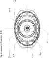
- Two guide sheaves (5) each with its sheave groove (56) lies in an axial plane (15) which is a main plane in the articulation sleeve (1).
- the guide sheaves are in an embodiment provided with roller or ball bearings for reducing the friction.
- the guide sheaves are laterally displaced, each to its side, of the axial passage's (13) middle so as its sheave groove (56) to envelope the axial passage (13) for the intervention cable (0). This is illustrated in Figs. 1, 2 , and 3 .
- the rigid, resilient intervention cable is already thread between the guide sheaves (5, 5), it is enveloped by the two sheave grooves (56, 56), please see Fig. 3 , and may not escape by slipping out laterally.
- a threaded, rigid, resilient intervention cable (0) mainly rest on the sheaves and will not touch any other part of the articulation sleeve's internally when it is in an operative state, regardless of how the bending restrictor is assembled from an alternating series of articulation sleeves and pipe sections (1, 2, 1, 2, ..) is laid, becaus the distance between pairs of guide sheaves (5, 5) is so short, in an embodiment 663 mm, please see below, and because the intervention cable (0) has such a high and homogenuous flexural rigidity that it will have even curvature. Longitudinally directed strong compression may of course incur the intervention cable to drag along a peripheral wall of the pipe section's (2) inner wall.
- the articulation sleeve (1) is provided with two opposite axially directed and flattened pivot funnels (4), wherein each pivot funnel (4) is arranged with its narrower end in towards each its spherical-sector seat (12).
- the two flattened pivot funnels are flattened in towards the same plane.
- the pivot funnel (4) In the axial plane (15) which is a main split plane through the articulation sleeve (1), the pivot funnel (4) has a funnel shape which allows the pipe section's (2) straight pipe piece (20) to pivot about the spherical-sector seat (12) in the axial plane (15) while tis oval wall forms a widening to a desired angle relative to the centreline of the central passage (13).
- the pivot funnel's (4) funnel shape is flattened in a second axial plane (15T) orthogonally to the first axial plane (15) so as for forcing the pipe sections (2) to rotate about the ball sector seat (12) only in the first axial plane (15).
- the articulation sleeve (1) will work as a swivel about each pipe section's (20) long axis.
- a bending restrictor comprising the assembled series of an alternating series of articulation sleeves and pipe sections (1, 2, 1, 2, 7) be able to form any path comprising curves and possibly straigt portions, only limited by the maximally allowed bending radius given by the geometry of the articulation sleeves' (1) and pipe sections' (2) geometry provides.
- a part of a curve may convert from lying along the ground, with vertical curve axis, to take off from the ground to a vertical direction with horizontal curve axis, to bend downwards again over a gooseneck, also with a horizontal curve axis, such as shown in Fig. 8 .
- the bending restrictor may be attached to the deck, to another structure, and to the gooseneck along its desired path when this is determined, before or after threading of the rigid, resilient intervention cable (0).
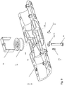
- the bending restrictor's articulation sleeve (1) is assembled to comprise two opposite adjacent generally symmetrical sleeve halves (1 h, 1 h) which may be split about a common axial plane (15). This considerably reduces the cost of the production tool for the articulation sleeve (1).
- Each sleeve half (1 h) comprises, in an embodiment, the following parts:
- the sleeve house (1) is, in consideration of the threading of the intervention cable, provided with oppositely directed guide funnels (41) which extend from a wider end adjacent to each its spherical-sector seat (12) and with each its narrower end in towards the guide sheaves (5, 5) which are arranged enveloping the middle portion of the central axial passage (13) for the intervention cable.
- guide funnel (41) here is shown embodied by its lower guide funnel shell half (41 h).
- the two opposite adjacent guide funnels (41) thus constitute a considerable portion of the central axial passage (13) between the two opposite spherical-sector seats (12), except from an open portion between the narrower parts of the guide funnels, between the two guide sheaves (5, 5).
- a lock element (3) comprises an axially directed locking sleeve (30) arranged for being thread in onto an end portion (133) of the two assembled sleeve halves (1 h, 1 h) in order to mutually lock them together such as shown in the assembled embodiment in Fig 5 , and in expanded view in Figs. 6 and 7 .
- the locking sleeve (30) may comprise an axial-parallel lock arm (31) arranged to extend into a corresponding axial parallel lock arm recess (32) in at least one of the two assembled shell halves (1 h), and mutually provided with a lock (311), preferably a snap lock mechanism
- a lock mechanism is simple and safe to operate for a rig worker and does not require heavy tools.
- Each guide sheave (5) is in an embodiment mounted in a U-shaped guide sheave bracket (52), please see Fig 9 in particular, but also Figs. 2 , Fig. 3 , and Fig. 6 , mounted longitudinally, parallel with the articulation sleeve's (1) main axis in a bracket slot (521) in said sleeve half (1 h) and which is held by a through shaft (51) in a guide sheave axle sleeve (54) in the chassis of a sleeve half (1 h).
- the guide sheave (5) is in an embodiment mounted in a laterally open guide sheave recess (55) centered about the axial plane (15). in this way one may replace a guide sheave (5) if required, by only unscrewing its axle bolt (51) and withdraw the guide sheave out through its guide sheave recess (55), and put in a replacement guide sheave (5) and reassemble the axle bolt (51).
- This allows a guide sheave to be replaced without the bending restrictor according to the invention having to be opened in its locking elements (3) and is a considerable operative advantage.
- the bending restrictor is, according to an embodiment of the invention, provided with external longitudinal and athwart reinforcement ribs (16, 17) over an end portion (133) externally on each half house (1 h) in the range on the outside of the pivot funnel (4) and the spherical-sector seat (12).
- Those reinforcement ribs (16, 17) for a solid and extensive backing for forces exerted by the pipe section (20) and its spherical sector (21) against the inner surface of the spherical sector seat (12, 12h) and the pivot funnel (4).
- These external reinforcement ribs (16, 17) have their back portions along an even, curved surface which is arranged for being covered totally by the lock sleeve (30). In this way axially extending rigid portions of the articulation sleeve (1) are formed and thus have high bending stiffness against bending moments which are exerted from within by the pipe section (2) and its spherical sector (21).
- Each half sleeve's (1 h) chassis is, in the guide funnel's (41) and the central axial passage's (13) range thus constituted by an outward shield wherein the reinforcement ribs (18, 19) extend inwards and supports or reinforces the guide funnel (41) and wherein other portions of the inward reinforcement ribs form the guide sheave recess (55) for the guide sheave's guide sheave bracket (52).
- the inward reinforcement ribs (18, 19 are thus connected in an external generally smooth, continuous shell which form the mid portion's outward surface, please see Fig. 5 .
- the invention expressed comprising an initially integral articulation sleeve
- the invention may be seen as if its two sleeve halves initially are assembled to an integral articulation sleeve, which may also be called an articulation sleeve house, ie. a sleeve-shaped house arranged for forming a double ball- and seat articulation between to adjacent pipe sections.
- a spherical seat (12) is arranged axially oppositely directed in each end of the articulation sleeve (1) and arranged for receiving oppositely directed pipe sections (2) wherein each pipe section (2) comprises a straight pipe piece (20) with a spherical sector (21) in either end.
- the spherical sector (21) has larger diameter than the straight pipe piece (20).
- each spherical sector seat (12) is arranged outward widening flattened funnels (4) in the same plane which allow each pipe section (2) to pivot about the ball seat (12) in this plane, and wherein the articulation sleeve (1) is splittable along this plane into two symmetrical sleeve halves (1 h).
- the spherical sector seat (12) extends at least to the angle V to either sides past the spherical sector's (21) larger diameter out from the pipe's (2) center in the direction towards the guide sheaves (5) and the central passage (13), and an equally large angle (V) away from the guide funnel's (4) inner portion, so as for the pipe end's spherical sector (21) to pivot with the angle V to either sides without touching bottom against the spherical sector seat's end portion.
- the spherical-sector seat (12) will, in addition to working as a pivot bearing for the spherical sector (21) also keep the spherical sector (21) in place, so as for [preventing] the pipe section (2) from move axially inwards or outwards.
- the bending restrictor of the invention becomes incompressible to a degree determined by the material strength and the manufacturing tolerances.
- the pipe sections are formed in aluminium, steel, or a plastic material such as polyamide.
- the articulation sleeve is formed in plastics, such as cured plastics, or aluminium, steel, bronze or other suitable material or alloy.
- the guide sheave (5) may be made in aluminium, steel, bronze, or plastics, e.g. nylon, and is mounted on an axle of steel with ball bearing of desired type.
- the lock sleeve (30) may advantageously be formed as an integral, smooth steel sleeve which is formed from 0.5 - 2 mm thickness plate, or in the form of a moulded plastic sleeve.
- the ball sector seat (12) is not tighter about the ball sector (21) than providing a swivel function in addition to the ball sector (21) may pivot in the ball sector seat (12).
- the intervention cable bending restrictor shown in Fig. 8 adapt to the path it is given along the deck and up along inclinations, only limited by the bending restrictor's smallelst allowed bending radius which is determined by the angular aperture of the guide [pivot] funnel (4), the length (Lss) between the spherical seats (12) and the length (Lpss) of the pipe sections (2).
- the inner diameter ⁇ 50 mm, wall thickness 4 mm and the external diameter of the pipe sections is in an embodiment 58 mm.
- the distance between the spherical seats is about 150 mm, in an embodiment 186 mm center-to-center of the spherical seats (4) [(12)].
- the aperture angle (2V) of the pivot funnel is about 10 to 30 degrees, in an embodiment 18 degrees, i.e. the largest angle the articulation sleeve (1) articulates between two adjacent pipe sections (2)
- Ten sections of an articulation sleeve (1) and a subsequent pipe section (2) thus provides a bending restrictor which describes a half circle of 10 x 18 degrees, i.e. 180 degrees arch.
- the intervention cable bending restrictor's length as measured along the chordal segments in a fully spanned half circle becomes in the given embodiment 10 x 663 mm, i.e. 6330 mm, which results in a smallest allowed bending radius of somewhat more than 2 m.
- the sheave (5) diameter is in an embodiment 56 mm, and provided with a round groove (56) with diameter 15 mm, thus with a diameter of about 50 mm at the bottom of the groove (56).
- the articulation sleeve (1) is provided with two axially oppositely directed guide funnels (41) running from their wider ends out adjacent to each its spherical sector seat (12) and inwardly with each their narrower end directed towards a central axial passage (13) for the intervention cable (0).
- the intervention cable's (0) end will run without encountering internally projecting edges through a pipe section (2), and emerge from the pipe section's spherical ball sector (21) aperture.
- the intervention cable's end will encounter at sharp angle against the guide funnel's (41) wall before the intervention cable's end (0) encounters the one or the other sheave's (5) sheave groove (56) and enter this sheave groove. Thereby it will run from the sheave's (5) sheave groove (56) into the narrower end of the opposite guide funnel (41) and avoids encountering the wall of this, and enters the aperture of the opposite adjacent pipe section's (2) spherical sector (21).
- the intervention cable's (0) end is thread past the actual articulation sleeve (1)
- the rodding of the intervention cable (0) may then continue through the entire bending restrictor.
- the intervention cable (0) may potentially touch only the guide sheave (5) in the articulation sleeve (1), and the inner wall of the pipe section (5) when thread.
- the rigid, resilient intervention cable (0) is so rigid that if the bending restrictor of the invention is straight, i.e. not bent, the intervention cable will rest on the guide sheaves (5) and will not touch the inner wall of the pipe section 2. The same is valid also when the bending restrictor is bent, in little tensile- or pressure loaded state the intervention cable will run only over the guide sheaves (5).
- the bending restrictor's path runs over from one arch in one plane, e.g. an arch attached to the deck, to a second arch in another plane, e.g. an arch from horizontally along the deck to vertically upwards to a gooseneck, the articulation sleeve (1) being at the transition will position itself in an intermediate position and the guide grooves (56) of the guide sheaves (5) will keep the intervention cable (0) in its correct place in the central axial passage (13).
- the sleeve housing (1) and each sleeve half (1 h) is designed so as for the entirety to have several non-obvious advantages.
Landscapes
- Engineering & Computer Science (AREA)
- Life Sciences & Earth Sciences (AREA)
- Geology (AREA)
- Mining & Mineral Resources (AREA)
- Mechanical Engineering (AREA)
- Physics & Mathematics (AREA)
- Environmental & Geological Engineering (AREA)
- Fluid Mechanics (AREA)
- General Life Sciences & Earth Sciences (AREA)
- Geochemistry & Mineralogy (AREA)
- Flexible Shafts (AREA)
Claims (14)
- Interventionskabel-Verbiegungsbegrenzer für ein starres, aber elastisches stangeförmiges Interventionskabel (0), wobei der Interventionskabel-Verbiegungsbegrenzer eine Folge von Rohrabschnitten (2) und Gelenkhülsen (1) aufweist,- wobei jeder Rohrabschnitt (2) ein gerades Rohrstück (20) mit je einem sphärischen Abschnitt (21) an jedem Ende umfasst.- Wobei jede Gelenkhülse (1) zwei axial entgegengesetzt ausgerichtete sphärische Aufnahmeabschnitte (12) zum Halten jeweils eines sphärischen Abschnitt (21) des jeweiligen Rohres (2) umfasst, wobei die sphärische Aufnahmeabschnitte (12) zu beiden Seiten eines zentralen axialen Durchgangs (13) für das Interventionskabel (0) angeordnet sind,gekennzeichnet durch- zwei Umlenkrollen (5), deren jeweiligen Rille (56) in der Achsebene (15) der Gelenkhülse (1) liegen und die seitlich derart entfernt von der Mitte axialen Durchgangs (13) angeordnet sind, dass sie den axiale Durchgang (13) für das Interventionskabel (0) umhüllen,- wobei die Gelenkhülse (1) mit zwei axial entgegengesetzt ausgerichtete und abgeflachten Schwenktrichtern (4) versehen ist, wobei jeder Schwenktrichter (4) mit seinem schmaleren Ende nach innen zu seinem jeweiligen sphärischen Aufnahmeabschnitt (12) gerichtet ist,- wobei der Schwenktrichter (4) in der Achsebene (15) eine Trichterform aufweist, die es dem Rohrabschnitt (20) erlaubt, sich um den sphärischen Aufnahmeabschnitt (12) in der axialen Ebene (15) zu verschwenken, und wobei die Trichterform des Schwenktrichters (4) in einer zweiten axialen Ebene (15T) senkrecht zur ersten Achsebene (15) so abgeflacht ist, dass die Rohrabschnitte (2) gezwungen sind, um ihren sphärischen Abschnitt (21) nur in der ersten Achsebene (15) zu schwenken.
- Interventionskabel-Verbiegungsbegrenzer nach Anspruch 1, wobei die Gelenkhülse (1) zwei axial entgegengesetzt ausgerichtete Führungstrichter (41) aufweist, deren breitere Enden jeweils nach außen in Richtung der sphärischen Aufnahmeabschnitte (12) und deren engeres Ende nach innen in Richtung des zentralen axialen Durchgangs (13) für das Interventionskabel (0) läuft.
- Interventionskabel-Verbiegungsbegrenzer nach Anspruch 1 oder 2, wobei die quer-gerichtete Achse jeder Umlenkrolle um den Radius der Rille (56) der Umlenkrolle (5) gegenüber dem zentralen axialen Durchgangs (13) versetzt ist, dass die jeweils gegenüberliegenden benachbarten Rillen (56) der Umlenkrollen (5, 5) dem zentralen axialen Durchgang (13) für das Interventionskabel (0) umschließen.
- Interventionskabel-Verbiegungsbegrenzer nach einem der Ansprüche 1, 2 oder 3, wobei die Gelenkhülse (1) zwei entgegengesetzte, im Wesentlichen symmetrische Hülsenhälften (1h, 1h) umfasst, die an einer gemeinsamen Achsebene (15) getrennt werden können.
- Interventionskabel-Verbiegungsbegrenzer nach Anspruch 4, wobei jede Hüllenhälfte (1h) umfasst:- eine sphärische Aufnahmeabschnittshälfte (12h), die zusammen mit einer gegenüberliegenden Aufnahmeabschnittshälfte (12h) den sphärischen Aufnahmeabschnitt (12) für einen sphärischen Abschnitt (21) bildet,- zwei entgegengesetzt entlang dem zentralen axialen Durchgang (13) ausgerichtete Aufnahmeabschnittshälfte (12h),- wobei der Achsbolzen (51) der Umlenkrolle (5) an einer Hüllenhälfte (1h) derart quer zum zentralen axialen Durchgang (13) befestigt ist, dass für zwei entgegengesetzte Hüllenhälften (1h) die Rillen (56) der Umlenkrollen (5, 5) den zentralen axialen Durchgang (13) für das Interventionskabel umschließen,- zwei axial entgegengesetzt ausgerichtete Schwenktrichterhälften (4h), jede mit ihrem schmaleren Ende zu ihrer jeweils benachbarten sphärischen Aufnahmeabschnittshälfte (12h) angeordnet, die jeweils zusammen mit einer Schwenktrichterhälfte (4h) einer entgegengesetzten Hüllenhälfte (1h) einen entgegengesetzten Schwenktrichter (4) bilden,- Verriegelungselemente (3), um entgegengesetzt zusammengebaute Hüllenhälfte (1h, 1h) zusammen, miteinander verriegelt und um zwei sphärische Abschnitte (21) zweier Rohrabschnitte (2) zu halten.
- Interventionskabel-Verbiegungsbegrenzer nach Anspruch 5, wobei jede Hüllenhälfte (1h) mit entgegengesetzt ausgerichtete Führungstrichterschalenhälften (41h) versehen ist, die sich von ihrem breiteren Enden jeweils benachbart zu ihren benachbarten sphärischen Aufnahmeabschnittshälften (12h) zum jeweiligen engeres Ende nach innen benachbart zum zentralen axialen Durchgangs (13) für das Interventionskabel erstrecken.
- Interventionskabel-Verbiegungsbegrenzer nach Anspruch 5, wobei jedes Verriegelungselement (3) eine axial ausgerichtete Verriegelungshülse (30) aufweist, die über einen Endabschnitt (133) der beiden zusammengesetzten Hülsenhälften (1h, 1h) schiebbar ist, um diese miteinander zu verriegeln.
- Interventionskabel-Verbiegungsbegrenzer nach Anspruch 7, wobei die Verriegelungshülse (30) einen parallel zur Achse hervorstehenden Verriegelungsarm (31) umfasst, der zum Hineinragen in eine reziproke Verriegelungsarmvertiefung (32) in wenigsten einer der beiden zusammengesetzten Hülsenhälften (1h) ausgebildet ist und gemeinsam mit einem Schloss (311), vorzugsweise einem Schnappverschluss, versehen sind.
- Interventionskabel-Verbiegungsbegrenzer nach Ansprüche 1, 2, 3 oder 4, wobei jede Führungsrolle in einem U-förmigen Führungsrollenbügel (52) befestigt ist, der in Längsrichtung parallel zur Hauptachse der Gelenkhülse (1) in einer Bügelnut (521) in einer Hüllenhälfte (1h) montiert und durch eine durchgehende Welle (51) in einer Führungsrollenachshülse (54) gehalten ist.
- Interventionskabel-Verbiegungsbegrenzer nach einem der vorhergehenden Ansprüche, wobei die Führungsrolle (5) in einer seitlich offenen Führungsrollenvertiefung (55) angeordnet ist, die um die Achsebene (15) zentriert ist.
- Interventionskabel-Verbiegungsbegrenzer nach einem der vorhergehenden Ansprüche, wobei außenliegende, sich längs-und quererstreckende Verstärkungsrippen (16, 17) auf einem Endabschnitt (133) auf jeder Hüllenhälfte (1h) im Bereich des Schwenktrichters (4, 4a) und der sphärische Aufnahmeabschnitte (12, 12h) vorgesehen sind.
- Interventionskabel-Verbiegungsbegrenzer nach einem der vorhergehenden Ansprüche, wobei innenliegende, sich längs-und quererstreckende Verstärkungsrippen (18, 19) in einem Mittelteil (134) zwischen den Endabschnitten (133) jeder Hüllenhälfte (1h) vorgesehen sind.
- Interventionskabel-Verbiegungsbegrenzer nach Ansprüchen 9, 10 und 12, wobei jede Hüllenhälfte (1h) im Bereich des Führungstrichters (41) und des zentralen axialen Durchgangs (13) eine äußere Abschirmung aufweist, wobei sich die innenliegenden Verstärkungsrippen (18, 19) nach innen erstrecken, den Führungstrichter (41) stützen und die Führungsrollenvertiefung (55) für den Führungsrollenbügel (52) bilden.
- Interventionskabel-Verbiegungsbegrenzer nach Ansprüchen 11, 12 und 13, wobei jede Hülsenhälfte (1h) mit ihren Verstärkungsrippen (16, 17, 18, 19) mit einer Projektion senkrecht zu der geteilten Ebene (15) geformt ist, um eine Formung ohne Hinterschneidung zu ermöglichen, d.h. sie können ohne störende Vorsprünge senkrecht zur der Trennebene der Form aus dieser herausgezogen werden.
Applications Claiming Priority (1)
| Application Number | Priority Date | Filing Date | Title |
|---|---|---|---|
| PCT/NO2013/050005 WO2014109642A1 (en) | 2013-01-09 | 2013-01-09 | A well intervention cable bending restriction for a rigid resilient rod-shaped intervention cable |
Publications (2)
| Publication Number | Publication Date |
|---|---|
| EP2943641A1 EP2943641A1 (de) | 2015-11-18 |
| EP2943641B1 true EP2943641B1 (de) | 2017-03-22 |
Family
ID=47750004
Family Applications (1)
| Application Number | Title | Priority Date | Filing Date |
|---|---|---|---|
| EP13706079.4A Active EP2943641B1 (de) | 2013-01-09 | 2013-01-09 | Bohrlochinterventionskabel-verbiegungsbeschränkung für ein starres, aber elastisches stangenförmiges interventionskabel |
Country Status (5)
| Country | Link |
|---|---|
| US (1) | US9932782B2 (de) |
| EP (1) | EP2943641B1 (de) |
| CA (1) | CA2897611C (de) |
| DK (1) | DK2943641T3 (de) |
| WO (1) | WO2014109642A1 (de) |
Families Citing this family (3)
| Publication number | Priority date | Publication date | Assignee | Title |
|---|---|---|---|---|
| WO2017086943A1 (en) | 2015-11-18 | 2017-05-26 | Halliburton Energy Services, Inc. | Segmented bend-limiter for slickline rope sockets and cable-heads |
| CN118257513A (zh) * | 2022-12-28 | 2024-06-28 | 中国石油天然气集团有限公司 | 一种连续管滚筒装置、连续管作业系统及其使用方法 |
| CN118067542B (zh) * | 2024-04-24 | 2024-07-05 | 山东亿群线缆股份有限公司 | 一种铜导体生产用的韧性检测装置及方法 |
Family Cites Families (9)
| Publication number | Priority date | Publication date | Assignee | Title |
|---|---|---|---|---|
| US1886820A (en) * | 1930-04-05 | 1932-11-08 | Lee Robert Edward | Drilling tool for lateral and angular drilling |
| US3627356A (en) * | 1969-11-19 | 1971-12-14 | Edwin A Anderson | Directional drilling apparatus with retrievable limiting device |
| US4091867A (en) * | 1977-01-14 | 1978-05-30 | Otis Engineering Corporation | Flexible conduit injection system |
| US4484641A (en) * | 1981-05-21 | 1984-11-27 | Dismukes Newton B | Tubulars for curved bore holes |
| US4842059A (en) * | 1988-09-16 | 1989-06-27 | Halliburton Logging Services, Inc. | Flex joint incorporating enclosed conductors |
| US5538092A (en) * | 1994-10-27 | 1996-07-23 | Ingersoll-Rand Company | Flexible drill pipe |
| FR2888825B1 (fr) * | 2005-07-22 | 2007-10-19 | Neos Entpr Unipersonnelle A Re | Gaine pour le guidage d'un fil |
| US7810556B2 (en) | 2005-10-03 | 2010-10-12 | Havinga Richard D | Lubricator for use with coiled tubing apparatus and universal rig having coiled tubing and top drive capability |
| NO20100174A1 (no) | 2010-02-03 | 2011-08-04 | C6 Technologies As | Boyingsbegrenser |
-
2013
- 2013-01-09 WO PCT/NO2013/050005 patent/WO2014109642A1/en not_active Ceased
- 2013-01-09 DK DK13706079.4T patent/DK2943641T3/en active
- 2013-01-09 US US14/759,563 patent/US9932782B2/en not_active Expired - Fee Related
- 2013-01-09 CA CA2897611A patent/CA2897611C/en active Active
- 2013-01-09 EP EP13706079.4A patent/EP2943641B1/de active Active
Non-Patent Citations (1)
| Title |
|---|
| None * |
Also Published As
| Publication number | Publication date |
|---|---|
| CA2897611A1 (en) | 2014-07-17 |
| WO2014109642A1 (en) | 2014-07-17 |
| EP2943641A1 (de) | 2015-11-18 |
| DK2943641T3 (en) | 2017-07-03 |
| CA2897611C (en) | 2018-10-30 |
| US9932782B2 (en) | 2018-04-03 |
| US20150345235A1 (en) | 2015-12-03 |
Similar Documents
| Publication | Publication Date | Title |
|---|---|---|
| KR102744741B1 (ko) | 특히 드릴링 리그를 위한 서비스 루프로서 거는 용도를 위한 라인 가이딩 장치 | |
| US10975629B2 (en) | Offshore installation | |
| CA2897611C (en) | A well intervention cable bending restriction for a rigid resilient rod-shaped intervention cable | |
| US20160333647A1 (en) | Conveyor apparatus | |
| US9739104B2 (en) | Conveyor apparatus | |
| US2730134A (en) | Casing for push-pull cable assembly | |
| EP3099888B1 (de) | Fördervorrichtung | |
| WO2011096820A2 (en) | A bend restrictor | |
| JP2023541513A (ja) | 懸吊アプリケーション、特に掘削リグ、掘削装置などのためのラインガイド装置 | |
| US10077619B2 (en) | Conveyor apparatus | |
| CN103154566B (zh) | 用于系泊缆绳的自对准索节 | |
| US11502487B2 (en) | Flexible clad protection system | |
| EP2795041B1 (de) | Flexible routingvorrichtung für bohrlochoperationen | |
| EP2154328B1 (de) | Durch Verbundstoff verbessertes metallisches Bohrsteigleitungssystem | |
| GB2496582A (en) | A ball and socket joint | |
| US20200095727A1 (en) | Armored Rigging System | |
| EP3762323B1 (de) | Erweiterbare schwere ausrüstung und längliches zugelement | |
| CN121519849A (zh) | 直连式可伸缩钻井工具 |
Legal Events
| Date | Code | Title | Description |
|---|---|---|---|
| PUAI | Public reference made under article 153(3) epc to a published international application that has entered the european phase |
Free format text: ORIGINAL CODE: 0009012 |
|
| 17P | Request for examination filed |
Effective date: 20150810 |
|
| AK | Designated contracting states |
Kind code of ref document: A1 Designated state(s): AL AT BE BG CH CY CZ DE DK EE ES FI FR GB GR HR HU IE IS IT LI LT LU LV MC MK MT NL NO PL PT RO RS SE SI SK SM TR |
|
| AX | Request for extension of the european patent |
Extension state: BA ME |
|
| RAP1 | Party data changed (applicant data changed or rights of an application transferred) |
Owner name: C6 TECHNOLOGIES AS |
|
| DAX | Request for extension of the european patent (deleted) | ||
| GRAP | Despatch of communication of intention to grant a patent |
Free format text: ORIGINAL CODE: EPIDOSNIGR1 |
|
| INTG | Intention to grant announced |
Effective date: 20161010 |
|
| GRAJ | Information related to disapproval of communication of intention to grant by the applicant or resumption of examination proceedings by the epo deleted |
Free format text: ORIGINAL CODE: EPIDOSDIGR1 |
|
| INTC | Intention to grant announced (deleted) | ||
| GRAP | Despatch of communication of intention to grant a patent |
Free format text: ORIGINAL CODE: EPIDOSNIGR1 |
|
| GRAS | Grant fee paid |
Free format text: ORIGINAL CODE: EPIDOSNIGR3 |
|
| GRAA | (expected) grant |
Free format text: ORIGINAL CODE: 0009210 |
|
| INTG | Intention to grant announced |
Effective date: 20170203 |
|
| AK | Designated contracting states |
Kind code of ref document: B1 Designated state(s): AL AT BE BG CH CY CZ DE DK EE ES FI FR GB GR HR HU IE IS IT LI LT LU LV MC MK MT NL NO PL PT RO RS SE SI SK SM TR |
|
| RAP1 | Party data changed (applicant data changed or rights of an application transferred) |
Owner name: C6 TECHNOLOGIES AS |
|
| REG | Reference to a national code |
Ref country code: GB Ref legal event code: FG4D |
|
| REG | Reference to a national code |
Ref country code: CH Ref legal event code: EP |
|
| REG | Reference to a national code |
Ref country code: AT Ref legal event code: REF Ref document number: 877998 Country of ref document: AT Kind code of ref document: T Effective date: 20170415 |
|
| REG | Reference to a national code |
Ref country code: IE Ref legal event code: FG4D |
|
| REG | Reference to a national code |
Ref country code: DE Ref legal event code: R096 Ref document number: 602013018852 Country of ref document: DE |
|
| REG | Reference to a national code |
Ref country code: DK Ref legal event code: T3 Effective date: 20170629 |
|
| REG | Reference to a national code |
Ref country code: NL Ref legal event code: MP Effective date: 20170322 |
|
| PG25 | Lapsed in a contracting state [announced via postgrant information from national office to epo] |
Ref country code: LT Free format text: LAPSE BECAUSE OF FAILURE TO SUBMIT A TRANSLATION OF THE DESCRIPTION OR TO PAY THE FEE WITHIN THE PRESCRIBED TIME-LIMIT Effective date: 20170322 Ref country code: FI Free format text: LAPSE BECAUSE OF FAILURE TO SUBMIT A TRANSLATION OF THE DESCRIPTION OR TO PAY THE FEE WITHIN THE PRESCRIBED TIME-LIMIT Effective date: 20170322 Ref country code: GR Free format text: LAPSE BECAUSE OF FAILURE TO SUBMIT A TRANSLATION OF THE DESCRIPTION OR TO PAY THE FEE WITHIN THE PRESCRIBED TIME-LIMIT Effective date: 20170623 Ref country code: HR Free format text: LAPSE BECAUSE OF FAILURE TO SUBMIT A TRANSLATION OF THE DESCRIPTION OR TO PAY THE FEE WITHIN THE PRESCRIBED TIME-LIMIT Effective date: 20170322 |
|
| REG | Reference to a national code |
Ref country code: LT Ref legal event code: MG4D |
|
| REG | Reference to a national code |
Ref country code: AT Ref legal event code: MK05 Ref document number: 877998 Country of ref document: AT Kind code of ref document: T Effective date: 20170322 |
|
| REG | Reference to a national code |
Ref country code: NO Ref legal event code: T2 Effective date: 20170322 |
|
| PG25 | Lapsed in a contracting state [announced via postgrant information from national office to epo] |
Ref country code: BG Free format text: LAPSE BECAUSE OF FAILURE TO SUBMIT A TRANSLATION OF THE DESCRIPTION OR TO PAY THE FEE WITHIN THE PRESCRIBED TIME-LIMIT Effective date: 20170622 Ref country code: SE Free format text: LAPSE BECAUSE OF FAILURE TO SUBMIT A TRANSLATION OF THE DESCRIPTION OR TO PAY THE FEE WITHIN THE PRESCRIBED TIME-LIMIT Effective date: 20170322 Ref country code: RS Free format text: LAPSE BECAUSE OF FAILURE TO SUBMIT A TRANSLATION OF THE DESCRIPTION OR TO PAY THE FEE WITHIN THE PRESCRIBED TIME-LIMIT Effective date: 20170322 Ref country code: LV Free format text: LAPSE BECAUSE OF FAILURE TO SUBMIT A TRANSLATION OF THE DESCRIPTION OR TO PAY THE FEE WITHIN THE PRESCRIBED TIME-LIMIT Effective date: 20170322 |
|
| PG25 | Lapsed in a contracting state [announced via postgrant information from national office to epo] |
Ref country code: NL Free format text: LAPSE BECAUSE OF FAILURE TO SUBMIT A TRANSLATION OF THE DESCRIPTION OR TO PAY THE FEE WITHIN THE PRESCRIBED TIME-LIMIT Effective date: 20170322 |
|
| PG25 | Lapsed in a contracting state [announced via postgrant information from national office to epo] |
Ref country code: CZ Free format text: LAPSE BECAUSE OF FAILURE TO SUBMIT A TRANSLATION OF THE DESCRIPTION OR TO PAY THE FEE WITHIN THE PRESCRIBED TIME-LIMIT Effective date: 20170322 Ref country code: ES Free format text: LAPSE BECAUSE OF FAILURE TO SUBMIT A TRANSLATION OF THE DESCRIPTION OR TO PAY THE FEE WITHIN THE PRESCRIBED TIME-LIMIT Effective date: 20170322 Ref country code: SK Free format text: LAPSE BECAUSE OF FAILURE TO SUBMIT A TRANSLATION OF THE DESCRIPTION OR TO PAY THE FEE WITHIN THE PRESCRIBED TIME-LIMIT Effective date: 20170322 Ref country code: AT Free format text: LAPSE BECAUSE OF FAILURE TO SUBMIT A TRANSLATION OF THE DESCRIPTION OR TO PAY THE FEE WITHIN THE PRESCRIBED TIME-LIMIT Effective date: 20170322 Ref country code: RO Free format text: LAPSE BECAUSE OF FAILURE TO SUBMIT A TRANSLATION OF THE DESCRIPTION OR TO PAY THE FEE WITHIN THE PRESCRIBED TIME-LIMIT Effective date: 20170322 Ref country code: EE Free format text: LAPSE BECAUSE OF FAILURE TO SUBMIT A TRANSLATION OF THE DESCRIPTION OR TO PAY THE FEE WITHIN THE PRESCRIBED TIME-LIMIT Effective date: 20170322 |
|
| PG25 | Lapsed in a contracting state [announced via postgrant information from national office to epo] |
Ref country code: PT Free format text: LAPSE BECAUSE OF FAILURE TO SUBMIT A TRANSLATION OF THE DESCRIPTION OR TO PAY THE FEE WITHIN THE PRESCRIBED TIME-LIMIT Effective date: 20170724 Ref country code: PL Free format text: LAPSE BECAUSE OF FAILURE TO SUBMIT A TRANSLATION OF THE DESCRIPTION OR TO PAY THE FEE WITHIN THE PRESCRIBED TIME-LIMIT Effective date: 20170322 Ref country code: SM Free format text: LAPSE BECAUSE OF FAILURE TO SUBMIT A TRANSLATION OF THE DESCRIPTION OR TO PAY THE FEE WITHIN THE PRESCRIBED TIME-LIMIT Effective date: 20170322 Ref country code: IS Free format text: LAPSE BECAUSE OF FAILURE TO SUBMIT A TRANSLATION OF THE DESCRIPTION OR TO PAY THE FEE WITHIN THE PRESCRIBED TIME-LIMIT Effective date: 20170722 |
|
| REG | Reference to a national code |
Ref country code: DE Ref legal event code: R097 Ref document number: 602013018852 Country of ref document: DE |
|
| REG | Reference to a national code |
Ref country code: FR Ref legal event code: PLFP Year of fee payment: 6 |
|
| PLBE | No opposition filed within time limit |
Free format text: ORIGINAL CODE: 0009261 |
|
| STAA | Information on the status of an ep patent application or granted ep patent |
Free format text: STATUS: NO OPPOSITION FILED WITHIN TIME LIMIT |
|
| 26N | No opposition filed |
Effective date: 20180102 |
|
| PG25 | Lapsed in a contracting state [announced via postgrant information from national office to epo] |
Ref country code: SI Free format text: LAPSE BECAUSE OF FAILURE TO SUBMIT A TRANSLATION OF THE DESCRIPTION OR TO PAY THE FEE WITHIN THE PRESCRIBED TIME-LIMIT Effective date: 20170322 Ref country code: IT Free format text: LAPSE BECAUSE OF FAILURE TO SUBMIT A TRANSLATION OF THE DESCRIPTION OR TO PAY THE FEE WITHIN THE PRESCRIBED TIME-LIMIT Effective date: 20170322 |
|
| REG | Reference to a national code |
Ref country code: DE Ref legal event code: R119 Ref document number: 602013018852 Country of ref document: DE |
|
| REG | Reference to a national code |
Ref country code: CH Ref legal event code: PL |
|
| PG25 | Lapsed in a contracting state [announced via postgrant information from national office to epo] |
Ref country code: DE Free format text: LAPSE BECAUSE OF NON-PAYMENT OF DUE FEES Effective date: 20180801 Ref country code: LU Free format text: LAPSE BECAUSE OF NON-PAYMENT OF DUE FEES Effective date: 20180109 |
|
| REG | Reference to a national code |
Ref country code: IE Ref legal event code: MM4A |
|
| REG | Reference to a national code |
Ref country code: BE Ref legal event code: MM Effective date: 20180131 |
|
| PG25 | Lapsed in a contracting state [announced via postgrant information from national office to epo] |
Ref country code: LI Free format text: LAPSE BECAUSE OF NON-PAYMENT OF DUE FEES Effective date: 20180131 Ref country code: CH Free format text: LAPSE BECAUSE OF NON-PAYMENT OF DUE FEES Effective date: 20180131 Ref country code: BE Free format text: LAPSE BECAUSE OF NON-PAYMENT OF DUE FEES Effective date: 20180131 |
|
| REG | Reference to a national code |
Ref country code: NO Ref legal event code: CREP Representative=s name: ZACCO NORWAY AS, POSTBOKS 2003 VIKA, 0125 OSLO |
|
| PG25 | Lapsed in a contracting state [announced via postgrant information from national office to epo] |
Ref country code: IE Free format text: LAPSE BECAUSE OF NON-PAYMENT OF DUE FEES Effective date: 20180109 |
|
| PG25 | Lapsed in a contracting state [announced via postgrant information from national office to epo] |
Ref country code: MC Free format text: LAPSE BECAUSE OF FAILURE TO SUBMIT A TRANSLATION OF THE DESCRIPTION OR TO PAY THE FEE WITHIN THE PRESCRIBED TIME-LIMIT Effective date: 20170322 |
|
| PG25 | Lapsed in a contracting state [announced via postgrant information from national office to epo] |
Ref country code: MT Free format text: LAPSE BECAUSE OF NON-PAYMENT OF DUE FEES Effective date: 20180109 |
|
| PG25 | Lapsed in a contracting state [announced via postgrant information from national office to epo] |
Ref country code: TR Free format text: LAPSE BECAUSE OF FAILURE TO SUBMIT A TRANSLATION OF THE DESCRIPTION OR TO PAY THE FEE WITHIN THE PRESCRIBED TIME-LIMIT Effective date: 20170322 |
|
| PG25 | Lapsed in a contracting state [announced via postgrant information from national office to epo] |
Ref country code: MK Free format text: LAPSE BECAUSE OF NON-PAYMENT OF DUE FEES Effective date: 20170322 Ref country code: HU Free format text: LAPSE BECAUSE OF FAILURE TO SUBMIT A TRANSLATION OF THE DESCRIPTION OR TO PAY THE FEE WITHIN THE PRESCRIBED TIME-LIMIT; INVALID AB INITIO Effective date: 20130109 Ref country code: CY Free format text: LAPSE BECAUSE OF FAILURE TO SUBMIT A TRANSLATION OF THE DESCRIPTION OR TO PAY THE FEE WITHIN THE PRESCRIBED TIME-LIMIT Effective date: 20170322 |
|
| PG25 | Lapsed in a contracting state [announced via postgrant information from national office to epo] |
Ref country code: AL Free format text: LAPSE BECAUSE OF FAILURE TO SUBMIT A TRANSLATION OF THE DESCRIPTION OR TO PAY THE FEE WITHIN THE PRESCRIBED TIME-LIMIT Effective date: 20170322 |
|
| REG | Reference to a national code |
Ref country code: NO Ref legal event code: CHAD Owner name: C6 TECHNOLOGIES AS, NO Ref country code: NO Ref legal event code: CHAD Owner name: COMTRAC AS, NO |
|
| REG | Reference to a national code |
Ref country code: GB Ref legal event code: 732E Free format text: REGISTERED BETWEEN 20210415 AND 20210421 |
|
| P01 | Opt-out of the competence of the unified patent court (upc) registered |
Effective date: 20230524 |
|
| PGFP | Annual fee paid to national office [announced via postgrant information from national office to epo] |
Ref country code: GB Payment date: 20251117 Year of fee payment: 14 |
|
| PGFP | Annual fee paid to national office [announced via postgrant information from national office to epo] |
Ref country code: NO Payment date: 20251218 Year of fee payment: 14 |
|
| PGFP | Annual fee paid to national office [announced via postgrant information from national office to epo] |
Ref country code: DK Payment date: 20251118 Year of fee payment: 14 |
|
| PGFP | Annual fee paid to national office [announced via postgrant information from national office to epo] |
Ref country code: FR Payment date: 20251120 Year of fee payment: 14 |