EP2943561B1 - Photobioreactor - Google Patents
Photobioreactor Download PDFInfo
- Publication number
- EP2943561B1 EP2943561B1 EP13805484.6A EP13805484A EP2943561B1 EP 2943561 B1 EP2943561 B1 EP 2943561B1 EP 13805484 A EP13805484 A EP 13805484A EP 2943561 B1 EP2943561 B1 EP 2943561B1
- Authority
- EP
- European Patent Office
- Prior art keywords
- chamber
- photobioreactor
- biomass
- outlet
- culture
- Prior art date
- Legal status (The legal status is an assumption and is not a legal conclusion. Google has not performed a legal analysis and makes no representation as to the accuracy of the status listed.)
- Active
Links
- 239000002028 Biomass Substances 0.000 claims description 83
- 239000002351 wastewater Substances 0.000 claims description 46
- XLYOFNOQVPJJNP-UHFFFAOYSA-N water Substances O XLYOFNOQVPJJNP-UHFFFAOYSA-N 0.000 claims description 39
- 239000012528 membrane Substances 0.000 claims description 36
- 241000195493 Cryptophyta Species 0.000 claims description 33
- 238000000034 method Methods 0.000 claims description 32
- 230000029087 digestion Effects 0.000 claims description 14
- 230000029553 photosynthesis Effects 0.000 claims description 5
- 238000010672 photosynthesis Methods 0.000 claims description 5
- 241000620196 Arthrospira maxima Species 0.000 claims description 2
- 241000894006 Bacteria Species 0.000 claims description 2
- 241000195649 Chlorella <Chlorellales> Species 0.000 claims description 2
- 240000009108 Chlorella vulgaris Species 0.000 claims description 2
- 235000007089 Chlorella vulgaris Nutrition 0.000 claims description 2
- 239000000356 contaminant Substances 0.000 claims description 2
- 239000000203 mixture Substances 0.000 claims description 2
- 241000195597 Chlamydomonas reinhardtii Species 0.000 claims 1
- 239000002184 metal Substances 0.000 description 16
- 229910052751 metal Inorganic materials 0.000 description 16
- CURLTUGMZLYLDI-UHFFFAOYSA-N Carbon dioxide Chemical compound O=C=O CURLTUGMZLYLDI-UHFFFAOYSA-N 0.000 description 14
- VNWKTOKETHGBQD-UHFFFAOYSA-N methane Chemical compound C VNWKTOKETHGBQD-UHFFFAOYSA-N 0.000 description 14
- 238000006243 chemical reaction Methods 0.000 description 13
- 150000002739 metals Chemical class 0.000 description 11
- 239000002105 nanoparticle Substances 0.000 description 9
- 230000008569 process Effects 0.000 description 8
- 238000004065 wastewater treatment Methods 0.000 description 8
- 229910019142 PO4 Inorganic materials 0.000 description 7
- 229910002092 carbon dioxide Inorganic materials 0.000 description 7
- 239000001569 carbon dioxide Substances 0.000 description 7
- 210000004027 cell Anatomy 0.000 description 7
- 235000021317 phosphate Nutrition 0.000 description 7
- 230000001580 bacterial effect Effects 0.000 description 5
- 230000001419 dependent effect Effects 0.000 description 5
- 239000007788 liquid Substances 0.000 description 5
- 238000004519 manufacturing process Methods 0.000 description 5
- NBIIXXVUZAFLBC-UHFFFAOYSA-K phosphate Chemical compound [O-]P([O-])([O-])=O NBIIXXVUZAFLBC-UHFFFAOYSA-K 0.000 description 5
- 239000010452 phosphate Substances 0.000 description 5
- 239000007787 solid Substances 0.000 description 5
- 230000014759 maintenance of location Effects 0.000 description 4
- 229930002875 chlorophyll Natural products 0.000 description 3
- 235000019804 chlorophyll Nutrition 0.000 description 3
- ATNHDLDRLWWWCB-AENOIHSZSA-M chlorophyll a Chemical compound C1([C@@H](C(=O)OC)C(=O)C2=C3C)=C2N2C3=CC(C(CC)=C3C)=[N+]4C3=CC3=C(C=C)C(C)=C5N3[Mg-2]42[N+]2=C1[C@@H](CCC(=O)OC\C=C(/C)CCC[C@H](C)CCC[C@H](C)CCCC(C)C)[C@H](C)C2=C5 ATNHDLDRLWWWCB-AENOIHSZSA-M 0.000 description 3
- 230000005611 electricity Effects 0.000 description 3
- 238000003306 harvesting Methods 0.000 description 3
- 230000000243 photosynthetic effect Effects 0.000 description 3
- 230000008901 benefit Effects 0.000 description 2
- 238000004061 bleaching Methods 0.000 description 2
- 150000001875 compounds Chemical class 0.000 description 2
- 238000012258 culturing Methods 0.000 description 2
- 238000010790 dilution Methods 0.000 description 2
- 239000012895 dilution Substances 0.000 description 2
- 230000007613 environmental effect Effects 0.000 description 2
- PCHJSUWPFVWCPO-UHFFFAOYSA-N gold Chemical compound [Au] PCHJSUWPFVWCPO-UHFFFAOYSA-N 0.000 description 2
- 229910052737 gold Inorganic materials 0.000 description 2
- 239000010931 gold Substances 0.000 description 2
- 238000005286 illumination Methods 0.000 description 2
- 230000036512 infertility Effects 0.000 description 2
- 238000012986 modification Methods 0.000 description 2
- 230000004048 modification Effects 0.000 description 2
- 150000003013 phosphoric acid derivatives Chemical class 0.000 description 2
- 239000011148 porous material Substances 0.000 description 2
- 238000005201 scrubbing Methods 0.000 description 2
- 239000002002 slurry Substances 0.000 description 2
- 239000010891 toxic waste Substances 0.000 description 2
- OKTJSMMVPCPJKN-UHFFFAOYSA-N Carbon Chemical compound [C] OKTJSMMVPCPJKN-UHFFFAOYSA-N 0.000 description 1
- RYGMFSIKBFXOCR-UHFFFAOYSA-N Copper Chemical compound [Cu] RYGMFSIKBFXOCR-UHFFFAOYSA-N 0.000 description 1
- QAOWNCQODCNURD-UHFFFAOYSA-L Sulfate Chemical compound [O-]S([O-])(=O)=O QAOWNCQODCNURD-UHFFFAOYSA-L 0.000 description 1
- 239000000654 additive Substances 0.000 description 1
- 230000033228 biological regulation Effects 0.000 description 1
- 229910052799 carbon Inorganic materials 0.000 description 1
- 210000002421 cell wall Anatomy 0.000 description 1
- 230000001413 cellular effect Effects 0.000 description 1
- 238000012993 chemical processing Methods 0.000 description 1
- 238000011109 contamination Methods 0.000 description 1
- 238000007796 conventional method Methods 0.000 description 1
- 229910052802 copper Inorganic materials 0.000 description 1
- 239000010949 copper Substances 0.000 description 1
- 230000003247 decreasing effect Effects 0.000 description 1
- 238000007865 diluting Methods 0.000 description 1
- 239000003337 fertilizer Substances 0.000 description 1
- 239000008394 flocculating agent Substances 0.000 description 1
- 239000012634 fragment Substances 0.000 description 1
- 230000005389 magnetism Effects 0.000 description 1
- 239000000463 material Substances 0.000 description 1
- 230000007246 mechanism Effects 0.000 description 1
- 235000015097 nutrients Nutrition 0.000 description 1
- 230000035515 penetration Effects 0.000 description 1
- 238000005498 polishing Methods 0.000 description 1
- 239000002244 precipitate Substances 0.000 description 1
- 230000004044 response Effects 0.000 description 1
- 230000000717 retained effect Effects 0.000 description 1
- 229920006395 saturated elastomer Polymers 0.000 description 1
- 238000000926 separation method Methods 0.000 description 1
- 239000000126 substance Substances 0.000 description 1
- 229910021653 sulphate ion Inorganic materials 0.000 description 1
- 239000002699 waste material Substances 0.000 description 1
Images

Classifications
-
- C—CHEMISTRY; METALLURGY
- C02—TREATMENT OF WATER, WASTE WATER, SEWAGE, OR SLUDGE
- C02F—TREATMENT OF WATER, WASTE WATER, SEWAGE, OR SLUDGE
- C02F3/00—Biological treatment of water, waste water, or sewage
- C02F3/32—Biological treatment of water, waste water, or sewage characterised by the animals or plants used, e.g. algae
- C02F3/322—Biological treatment of water, waste water, or sewage characterised by the animals or plants used, e.g. algae use of algae
-
- C—CHEMISTRY; METALLURGY
- C02—TREATMENT OF WATER, WASTE WATER, SEWAGE, OR SLUDGE
- C02F—TREATMENT OF WATER, WASTE WATER, SEWAGE, OR SLUDGE
- C02F3/00—Biological treatment of water, waste water, or sewage
- C02F3/28—Anaerobic digestion processes
-
- C—CHEMISTRY; METALLURGY
- C02—TREATMENT OF WATER, WASTE WATER, SEWAGE, OR SLUDGE
- C02F—TREATMENT OF WATER, WASTE WATER, SEWAGE, OR SLUDGE
- C02F3/00—Biological treatment of water, waste water, or sewage
- C02F3/32—Biological treatment of water, waste water, or sewage characterised by the animals or plants used, e.g. algae
-
- C—CHEMISTRY; METALLURGY
- C12—BIOCHEMISTRY; BEER; SPIRITS; WINE; VINEGAR; MICROBIOLOGY; ENZYMOLOGY; MUTATION OR GENETIC ENGINEERING
- C12M—APPARATUS FOR ENZYMOLOGY OR MICROBIOLOGY; APPARATUS FOR CULTURING MICROORGANISMS FOR PRODUCING BIOMASS, FOR GROWING CELLS OR FOR OBTAINING FERMENTATION OR METABOLIC PRODUCTS, i.e. BIOREACTORS OR FERMENTERS
- C12M21/00—Bioreactors or fermenters specially adapted for specific uses
- C12M21/02—Photobioreactors
-
- C—CHEMISTRY; METALLURGY
- C12—BIOCHEMISTRY; BEER; SPIRITS; WINE; VINEGAR; MICROBIOLOGY; ENZYMOLOGY; MUTATION OR GENETIC ENGINEERING
- C12M—APPARATUS FOR ENZYMOLOGY OR MICROBIOLOGY; APPARATUS FOR CULTURING MICROORGANISMS FOR PRODUCING BIOMASS, FOR GROWING CELLS OR FOR OBTAINING FERMENTATION OR METABOLIC PRODUCTS, i.e. BIOREACTORS OR FERMENTERS
- C12M21/00—Bioreactors or fermenters specially adapted for specific uses
- C12M21/04—Bioreactors or fermenters specially adapted for specific uses for producing gas, e.g. biogas
-
- C—CHEMISTRY; METALLURGY
- C12—BIOCHEMISTRY; BEER; SPIRITS; WINE; VINEGAR; MICROBIOLOGY; ENZYMOLOGY; MUTATION OR GENETIC ENGINEERING
- C12M—APPARATUS FOR ENZYMOLOGY OR MICROBIOLOGY; APPARATUS FOR CULTURING MICROORGANISMS FOR PRODUCING BIOMASS, FOR GROWING CELLS OR FOR OBTAINING FERMENTATION OR METABOLIC PRODUCTS, i.e. BIOREACTORS OR FERMENTERS
- C12M29/00—Means for introduction, extraction or recirculation of materials, e.g. pumps
- C12M29/18—External loop; Means for reintroduction of fermented biomass or liquid percolate
-
- C—CHEMISTRY; METALLURGY
- C12—BIOCHEMISTRY; BEER; SPIRITS; WINE; VINEGAR; MICROBIOLOGY; ENZYMOLOGY; MUTATION OR GENETIC ENGINEERING
- C12M—APPARATUS FOR ENZYMOLOGY OR MICROBIOLOGY; APPARATUS FOR CULTURING MICROORGANISMS FOR PRODUCING BIOMASS, FOR GROWING CELLS OR FOR OBTAINING FERMENTATION OR METABOLIC PRODUCTS, i.e. BIOREACTORS OR FERMENTERS
- C12M31/00—Means for providing, directing, scattering or concentrating light
- C12M31/10—Means for providing, directing, scattering or concentrating light by light emitting elements located inside the reactor, e.g. LED or OLED
-
- C—CHEMISTRY; METALLURGY
- C12—BIOCHEMISTRY; BEER; SPIRITS; WINE; VINEGAR; MICROBIOLOGY; ENZYMOLOGY; MUTATION OR GENETIC ENGINEERING
- C12M—APPARATUS FOR ENZYMOLOGY OR MICROBIOLOGY; APPARATUS FOR CULTURING MICROORGANISMS FOR PRODUCING BIOMASS, FOR GROWING CELLS OR FOR OBTAINING FERMENTATION OR METABOLIC PRODUCTS, i.e. BIOREACTORS OR FERMENTERS
- C12M43/00—Combinations of bioreactors or fermenters with other apparatus
-
- C—CHEMISTRY; METALLURGY
- C02—TREATMENT OF WATER, WASTE WATER, SEWAGE, OR SLUDGE
- C02F—TREATMENT OF WATER, WASTE WATER, SEWAGE, OR SLUDGE
- C02F11/00—Treatment of sludge; Devices therefor
- C02F11/02—Biological treatment
- C02F11/04—Anaerobic treatment; Production of methane by such processes
-
- C—CHEMISTRY; METALLURGY
- C02—TREATMENT OF WATER, WASTE WATER, SEWAGE, OR SLUDGE
- C02F—TREATMENT OF WATER, WASTE WATER, SEWAGE, OR SLUDGE
- C02F2101/00—Nature of the contaminant
- C02F2101/10—Inorganic compounds
- C02F2101/105—Phosphorus compounds
-
- C—CHEMISTRY; METALLURGY
- C02—TREATMENT OF WATER, WASTE WATER, SEWAGE, OR SLUDGE
- C02F—TREATMENT OF WATER, WASTE WATER, SEWAGE, OR SLUDGE
- C02F2201/00—Apparatus for treatment of water, waste water or sewage
- C02F2201/32—Details relating to UV-irradiation devices
- C02F2201/322—Lamp arrangement
- C02F2201/3222—Units using UV-light emitting diodes [LED]
-
- C—CHEMISTRY; METALLURGY
- C02—TREATMENT OF WATER, WASTE WATER, SEWAGE, OR SLUDGE
- C02F—TREATMENT OF WATER, WASTE WATER, SEWAGE, OR SLUDGE
- C02F2203/00—Apparatus and plants for the biological treatment of water, waste water or sewage
-
- C—CHEMISTRY; METALLURGY
- C02—TREATMENT OF WATER, WASTE WATER, SEWAGE, OR SLUDGE
- C02F—TREATMENT OF WATER, WASTE WATER, SEWAGE, OR SLUDGE
- C02F3/00—Biological treatment of water, waste water, or sewage
- C02F3/02—Aerobic processes
- C02F3/12—Activated sludge processes
- C02F3/1236—Particular type of activated sludge installations
- C02F3/1268—Membrane bioreactor systems
-
- Y—GENERAL TAGGING OF NEW TECHNOLOGICAL DEVELOPMENTS; GENERAL TAGGING OF CROSS-SECTIONAL TECHNOLOGIES SPANNING OVER SEVERAL SECTIONS OF THE IPC; TECHNICAL SUBJECTS COVERED BY FORMER USPC CROSS-REFERENCE ART COLLECTIONS [XRACs] AND DIGESTS
- Y02—TECHNOLOGIES OR APPLICATIONS FOR MITIGATION OR ADAPTATION AGAINST CLIMATE CHANGE
- Y02E—REDUCTION OF GREENHOUSE GAS [GHG] EMISSIONS, RELATED TO ENERGY GENERATION, TRANSMISSION OR DISTRIBUTION
- Y02E50/00—Technologies for the production of fuel of non-fossil origin
- Y02E50/30—Fuel from waste, e.g. synthetic alcohol or diesel
-
- Y—GENERAL TAGGING OF NEW TECHNOLOGICAL DEVELOPMENTS; GENERAL TAGGING OF CROSS-SECTIONAL TECHNOLOGIES SPANNING OVER SEVERAL SECTIONS OF THE IPC; TECHNICAL SUBJECTS COVERED BY FORMER USPC CROSS-REFERENCE ART COLLECTIONS [XRACs] AND DIGESTS
- Y02—TECHNOLOGIES OR APPLICATIONS FOR MITIGATION OR ADAPTATION AGAINST CLIMATE CHANGE
- Y02W—CLIMATE CHANGE MITIGATION TECHNOLOGIES RELATED TO WASTEWATER TREATMENT OR WASTE MANAGEMENT
- Y02W10/00—Technologies for wastewater treatment
- Y02W10/10—Biological treatment of water, waste water, or sewage
-
- Y—GENERAL TAGGING OF NEW TECHNOLOGICAL DEVELOPMENTS; GENERAL TAGGING OF CROSS-SECTIONAL TECHNOLOGIES SPANNING OVER SEVERAL SECTIONS OF THE IPC; TECHNICAL SUBJECTS COVERED BY FORMER USPC CROSS-REFERENCE ART COLLECTIONS [XRACs] AND DIGESTS
- Y02—TECHNOLOGIES OR APPLICATIONS FOR MITIGATION OR ADAPTATION AGAINST CLIMATE CHANGE
- Y02W—CLIMATE CHANGE MITIGATION TECHNOLOGIES RELATED TO WASTEWATER TREATMENT OR WASTE MANAGEMENT
- Y02W10/00—Technologies for wastewater treatment
- Y02W10/30—Wastewater or sewage treatment systems using renewable energies
- Y02W10/37—Wastewater or sewage treatment systems using renewable energies using solar energy
Definitions
- the present invention relates to a photobioreactor, a system and a method for algal based waste water treatment.
- algae can be used to significantly reduce the phosphate content in waste water.
- the algae is generally exposed to the waste water within a photobioreactor.
- Conventional methods and systems for using algae to treat waste water have a number of drawbacks including requiring a large amount of space, contamination problems, energy requirement, vulnerability to the weather, and unsuitability for industrial scale use.
- the conventional systems typically make use of sunlight and outdoor culturing. These systems are therefore limited to regions with optimal conditions and as a result have reduced efficiency and limit the scope for using these systems to treat waste water with algae on an industrial scale.
- US 2011/107664 describes a culturing system for algae, the algae being output from the system to an open wastewater treatment pond.
- US 2011/247977 describes an open tank system for treatment of wastewater, in which overhead lighting and a separation membrane is used to separate treated water from the microalgae of the tank.
- US 2011/266215 describes a system in which wasterwater is pretreated with nutrients and trace metals, and mixed with returning activated algae, before being introduced into a generic photobioreactor.
- the present invention provides a photobioreactor for the treatment of waste water that includes contaminants, the photobioreactor comprising:
- the present invention provides a method of treating waste water comprising contacting a culture of algae with a waste water input in a photobioreactor or system as described herein to produce an algal biomass and a treated waste water output.
- Embodiments of the present invention therefore, advantageously, provide an efficient, highly productive, all climate, internally lit, continuous or substantially continuous photobioreactor and the use thereof to treat waste water.
- the photobioreactor is preferably fully isolated from contaminating environments.
- continuous or substantially continuous culture is used herein to refer to a culture which is present within the chamber of the photobioreactor throughout the treatment process while simultaneously allowing the harvesting of a proportion of biomass when the biomass within the chamber reaches a predetermined maximum level. No additional culture is required to be added to the chamber.
- the continuous or substantially continuous culture is present within the chamber at a concentration of at least a predetermined minimum level.
- the removal of the biomass causes dilution of the culture within the chamber during the treatment process.
- the dilution of the culture is controlled so that the concentration of the continuous or substantially continuous culture within the chamber does not fall below the predetermined minimum value.
- the photobioreactor may be arranged such that the retention time of the biomass within the chamber is independent from the retention time of the water within the chamber. By separating the hydraulic retention time from the biomass retention time, treated water can be continuously flowed through the photobioreactor from the inlet to the outlet allowing constant fresh addition of waste water and advantageously boosting the maximum biomass capacity.
- the photobioreactor therefore enables a significant increase of waste water to be treated by a given volume of culture of algae.
- the biomass may be harvested when the biomass reaches a predetermined maximum limit.
- the chamber may have any suitable shape, for example the chamber may be substantially cylindrical in shape.
- the outlet may comprise a first outlet arranged in use for allowing the continuous flow of treated water from the chamber and a second outlet arranged in use to selectively remove a proportion of the biomass.
- the biomass may be removed with the treated waste water.
- the arrangement of the first and second outlets may be such that the distance between the first outlet and the base of the chamber may be greater than the distance between the second outlet and the base of the chamber.
- the first and second outlets may be aligned along a direction extending substantially parallel to the longitudinal axis of the chamber.
- the photobioreactor could be installed towards the end of existing waste water treatment systems.
- the photobioreactor may be used as a final polishing stage at the end of existing waste water treatment systems.
- the photobioreactor of the present invention may offer the potential to save space compared to conventional systems.
- the photobioreactor and method of the invention may provide a high rate of throughput of water treatment while still providing the harvesting of biomass.
- the biomass may be harvested at a rate comparable to growing and harvesting a single batch in a non-continuous conventional system.
- the harvested biomass may then be introduced into an anaerobic digester, for example for gas production.
- the method may further comprise determining the biomass increase/growth rate and comparing to a predetermined biomass/cell count, for example an ideal biomass/cell count, and regularly diluting the culture accordingly
- the culture may be diluted every 24 hours in order to maintain the biomass at this predetermined level.
- the culture may be diluted by for example 20% every 24 hours.
- the at least one light source may be calibrated to emit light predominantly at wavelengths which enhance photosynthesis.
- the at least one light source may therefore be calibrated to enable more efficient growth rate of the culture. Chlorophyll is most efficient at absorbing red light. Light from other wavelengths is only partially absorbed.
- the at least one light source is preferably calibrated to provide light having predominantly a wavelength in the region of 620 to 645 nm, for example to provide red light.
- the light source may emit light having a greater proportion of red light than blue light.
- the at least one light source may comprise at least one light emitting diode (LED). LEDs have the vast potential for power savings making artificial illumination of photobioreactors cost effective.
- LEDs have the vast potential for power savings making artificial illumination of photobioreactors cost effective.
- the photobioreactor may comprise at least one light source in the form of an elongate column.
- the at least one LED may be in the form of an elongate column.
- the elongate column may be arranged to extend within the chamber in a direction extending substantially parallel to the longitudinal axis of the chamber.
- the elongate column may be arranged to extend in a direction extending substantially perpendicular to the base of the chamber.
- the at least one elongate columns may be spaced apart from each other so as to provide uniform light coverage, for example uniform light intensity within the chamber.
- the light source(s) may be programmable.
- the LED(s) may be high frequency flashing light(s) (FLE).
- the high frequency flashing light(s) may be adjusted to control the amount of light that impinges the culture.
- the photosynthetic reaction taking place in chlorophyll in the culture proceeds at a maximum energetic efficiency.
- the reaction can be split in to two sections; the light and dark dependent reaction centres. Initially the light dependent reaction in chlorophyll captures the energy from incoming light in the light receiving centre. Through a number of chemical reactions the initial energy is passed to a dark reaction centre for use in further photosynthetic reactions.
- the light dependent reaction centre can only absorb a set amount of energy per second before the reaction centre becomes saturated. If excess light is rendered into the light reaction centre e.g. by continuous lighting, this energy is wasted. This wasted energy has the potential to lead to photo bleaching which may reduce the efficiency of the photosynthesis. Photo bleaching may also cause permanent damage to the cell.
- high frequency flashing lights advantageously allows the emission of light to be controlled such that the light energy is only provided when the light dependent reaction of photosynthesis is receptive to the energy. Accordingly, the use of high frequency flashing lights helps to prevent over saturation of the light reaction centre and as such helps to increase the productivity of the cells photosynthesis reactions.
- the photobioreactor and method of embodiments of the present invention can be used to treat waste water with improved efficiency compared to conventional systems.
- the flashing rate of the high frequency flashing lights is preferably arranged in use to flash so that the ratio of the period of time in which light is emitted to the period of time in which light is not emitted is approximately 1:2.
- the high frequency flashing lights may be arranged in use to flash at a rate to emit 10 microseconds of light for every 20 microseconds of dark.
- the use of high frequency flashing lights also has the further advantage of providing a significant energy saving compared to a non-flashing light source.
- cells of the culture can be damaged by the use of light having an intensity greater than a threshold intensity.
- the photobioreactor can use high frequency flashing lights to emit light with an intensity above the threshold intensity without causing damage to the culture. The applicant has found that when using high frequency flashing lights this increased light intensity of the light pulse is not provided long enough to damage the photosynthetic mechanisms within the cells.
- the photobioreactor may therefore enable light from the light source to penetrate to a greater extent, for example to a greater depth within the culture than conventional systems due to the provision of a flashing light source emitting light pulses having increased intensity, for example an intensity greater than the threshold intensity.
- the increased penetration distance within the culture increases the photoactive layer of the culture.
- the depth of the photoactive layer is one of the major limitations of conventional photobioreactors.
- Conventional bioreactors, having continuous illumination, are designed with small capacities in order to reduce light energy waste resulting from the photoactive layer being short.
- the light source may be a variable intensity light source. Accordingly, in use the light intensity of the light source may be variable.
- the method may further comprise adjusting the light intensity of the light source during the wastewater treatment process.
- the light intensity may be varied in response to the increasing density of the culture. For example, as the treatment process progresses and the culture density increases within the photobioreactor, the light intensity may be increased.
- the light intensity of the light source may be directly dependent on the density of the culture.
- the light intensity of the light source may be increased as a function of time as the treatment process continues. The light intensity may be increased over a predetermined period of time.
- the light intensity of the light source may be controlled or varied so as to provide the required level of lighting to the culture for each stage of the process.
- the photobioreactor may further comprise an insulating layer.
- the insulating layer may be arranged in use to regulate/control the heat within the chamber.
- the waste water inlet and/or outlet(s) may each comprise a valve.
- the photobioreactor comprises at least one membrane.
- the photobioreactor may comprise a membrane arranged in use to ensure the sterility of the culture is maintained.
- the first membrane may be positioned adjacent to or at the waste water inlet into the treatment chamber.
- the photobioreactor comprises a membrane arranged in use to retain the culture within the treatment chamber while allowing the treated waste water to pass through the outlet.
- the pore size of the membrane is preferably selected to retain the biomass within said chamber.
- a membrane may be located adjacent to or at the treated water and biomass outlet. The membrane may be moveable between an open position allowing the biomass/treated water to flow through said outlet and a closed position in which the biomass is retained within the chamber and treated water flows through the outlet.
- the membrane may be arranged in use to be moved to the open position when the biomass within the chamber reaches the predetermined maximum level.
- the chamber comprises a first outlet for removal of treated waste water and a second outlet arranged in use for selectively removing a proportion of biomass.
- a membrane is arranged within the chamber so as to be located between said first and second outlet. The membrane is arranged in use to retain the biomass within the chamber while allowing treated waste water to be removed by the first outlet.
- the membrane may be arranged within the treatment chamber to extend at an angle, for example substantially perpendicular, to the longitudinal axis of the chamber at a predetermined height above the base of the chamber. The entire periphery of the membrane is in contact with the chamber walls.
- the membrane is preferably located within the chamber below the first outlet, for example closer to the base of the chamber than the first outlet.
- the second outlet is preferably arranged closer to the base of the chamber than the membrane. In this arrangement, the membrane prevents the biomass from being removed from the chamber by the first outlet.
- the pore size of the membrane is preferably selected to retain the biomass within said chamber.
- the chamber further comprises a gas diffuser.
- the gas diffuser is arranged to extend across the full base of the chamber.
- the gas diffuser is preferably arranged to prevent dead zones and to provide scrubbing to the sides of the chamber and/or the internal light source.
- the air within the chamber flows upwardly from said base of the chamber.
- the chamber may further comprise a carbon dioxide nanodiffuser.
- the method of the present invention results in an algal biomass being formed during the treatment of waste water.
- the energy bound within the whole cellular material of the algal biomass may economically be recovered by anaerobic digestion using bacteria.
- the method may therefore further comprise contacting said biomass with at least one bacterial strain for anaerobic digestion of said biomass.
- the biomass is preferably contacted with at least one bacterial strain for anaerobic digestion within at least one anaerobic digester.
- the anaerobic digestion may be performed downstream of said photobioreactor.
- the present invention provides a waste water system comprising at least one photobioreactor as described herein and at least one anaerobic digester for receiving the biomass from the photobioreactor(s) and at least one bacterial strain adapted for digestion of algae.
- the anaerobic digester is preferably adapted for digestion of algae.
- the at least one anaerobic digester is preferably located downstream of the photobioreactor(s).
- the system may comprise the photobioreactor and the digester as an integral unit.
- the whole of the biomass may be utilised for gas production, such as for example methane gas for power and carbon dioxide.
- the carbon dioxide may be separated and used, for example recycled as a feed for the algae within the chamber.
- the liquid and solid fractions leftover are not contaminated by chemical additives.
- the liquid and solid fractions may be used as liquid or solid fertiliser and/or conditioner.
- the remaining fractions may include sequestered carbon and clean water. No further chemical processing is required and digestion of the algal biomass advantageously does not produce any toxic waste.
- the algal strain for use with the photobioreactor, the method and the system of the invention may be selected from Chlorella vulgaris, Spirulina maxima, Chlorella, Scenesmus, and Chlamydomas reinhardtii, or a mixture thereof.
- the photobioreactor may further comprise a further inlet for supplying metals, such as for example gold and rare earths, to the treatment chamber.
- the metals may be provided in the form of a slurry.
- the method may therefore further comprise the step of introducing metals to the treatment chamber of the photobioreactor.
- the culture ingests the metal and precipitates nanoparticles of the metal within the cell. Nanoparticles of metals are important in modern science and electronics manufacturing. Once the treated waste water and biomass (containing the ingested nanoparticles of metal) pass into the digester, digestion of the algae results in the break up of the biomass and as such provides an easy method for liberating nanoparticles.
- the method may further comprise the step of recovering the nanoparticles of metals during anaerobic digestion of the biomass, for example in the digester.
- the metals may be magnetic.
- the method may comprise use of magnetism to recover nanoparticles of ingested magnetic metals.
- Embodiments of the photobioreatcor and method of the invention may be used to treat waste water and to produce nanoparticles of metals simultaneously.
- the system may comprise an anaerobic digester for receiving biomass from a plurality of photobioreactor(s).
- the system may further comprise a separator arranged in use to separate the treated water from the treated water and biomass obtained from the outlet of the photobioreactor, for example the separator is preferably located between the photobioreactor and the digester.
- the photobioreactor and method of the invention eliminate the limitation of most renewable power, i.e. the variable supply of wind, sun or other environmental parameter
- the biogas produced by the anaerobic digestion of the biomass within the anaerobic digester(s) may be collected.
- the biogas is preferably methane.
- the anaerobic digester(s) may be arranged in use to produce methane at a rate of at least 0.25 L CH 4 g VS -1 , preferably at least 0.5 L CH 4 g VS -1 .
- the photobioreactor, system and method of the invention may be used to generate power, for example electricity.
- a method for generating electricity comprising using the biogas generated by the method as herein described and converting said biogas to electricity using a power generator.
- the photobioreactor 10 comprises a cylindrical treatment chamber 12 comprising a waste water inlet 14, six internal LEDs 16 and a treated water outlet 18.
- the chamber 12 is substantially cylindrical in shape.
- the LEDs 16 are elongate columns.
- the LEDs 16 extend substantially parallel to the longitudinal axis of the chamber 12.
- the LEDs 16 are spaced apart from each other within the chamber to provide uniform light intensity within the chamber 12.
- the waste water inlet 14 further comprises a valve 19 and a first membrane 20 arranged in use to maintain the sterility.
- the treated water outlet 18 comprises a first outlet 21 for maintaining a continuous flow through of treated water.
- the chamber 12 also comprises a second membrane 22 extending substantially perpendicular to the longitudinal axis of the chamber 12. The second membrane 22 is located closer to the base of the chamber 12 than the first outlet 20. The second membrane 22 is located at a height between the inlet 14 and the first outlet 20. The entire periphery of the second membrane 22 is in contact with the walls of the chamber 12. The second membrane 22 is selected so as to prevent biomass from flowing through the first outlet 20.
- the chamber comprises a second outlet 24 arranged in use to selectively remove a proportion of the biomass produced within said chamber 12 when said biomass reaches a predetermined maximum level so as to maintain a continuous or substantially continuous culture of algae within said chamber 12.
- the first outlet 20 is located at a predetermined distance above the second outlet 24.
- the second outlet 24 is located closer to the base of the chamber 12 than the second membrane 22.
- the chamber 12 further comprises a gas diffuser 26 at the base 28 of the chamber 12.
- the diffuser 26 is arranged to extend across the full base 28 of the chamber 12.
- the diffuser 26 is arranged to prevent deadzones within the chamber 12 and to provide scrubbing to the sides of the chamber 12 and/or the internal light source.
- the air 30 within the chamber 12 flows upwardly from said base 28.
- the chamber 12 further comprises two carbon dioxide nanodiffusers 34 locating on opposing surfaces of the chamber 12.
- a culture of algae (not shown) is placed within the chamber 12.
- the culture (not shown) is placed towards the base of the chamber 12 and at a location below the height of the second membrane 22.
- Waste water enters the chamber 12 through the inlet 14. Air is introduced through the base 28.
- the waste water is contacted with the culture.
- the LEDs provide light to the culture.
- the LEDs are arranged to provide a ratio of red: blue light of 3:1.
- the LEDs are also arranged to be high frequency flashing lights and the light intensity of the LEDs is arranged in use to increase as the biomass within the chamber 12 increases.
- the treated water continually flows through first outlet 20.
- the culture reduces the phosphate level within the water.
- the second membrane 22 prevents biomass from being removed through the first outlet 20.
- the growth rate of the algae is determined, and the second outlet 24 is selectively used to remove a proportion of the biomass produced within the chamber 12 when said biomass reaches a predetermined maximum level so as to maintain a continuous or substantially continuous culture of algae within said chamber 12.
- the second outlet 24 is in a closed position.
- the second outlet 24 moves to an open position allowing biomass/treated water to flow from the chamber 12.
- the outlet 24 When the level of biomass within the chamber 12 is suitably decreased the outlet 24 will be closed. For example, 20% of the biomass may be allowed to leave the chamber.
- the removed biomass and treated water removed through the second outlet 24 then flows to a separator (not shown) which separates or filters the biomass from the treated waste water.
- the biomass is then introduced into an anaerobic digester.
- the anaerobic digester comprises at least one bacterial strain for digesting the biomass.
- the biomass is converted within the anaerobic digester (not shown) to methane gas and carbon dioxide.
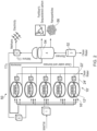
- a waste water treatment system 50 may typically comprise multiple photobioreactors. As shown in Figure 2 , the waste water treatment system 50 may comprise five photobioreactors 10' as shown in Figure 1 .
- the photobioreactors 10' may each further comprise an inlet (not shown) for supplying metals, such as for example gold and copper to the treatment chamber 12'.
- the waste water is introduced to the treatment chambers 12'.
- a slurry of metal is also introduced to the treatment chambers 12'.
- the LEDs 16' provide a light source to the culture of algae.
- the culture removes phosphates from the waste water and also ingests the metals to form nanoparticles.
- the first waste water outlets 22' of the photobioreactors 10' are connected to supply a stream of clean treated water.
- the second waste water outlets 24' of the photobioreactors 10' are connected to supply a stream of treated water and biomass.
- the stream provided by the second waste water outlets 24' is supplied to a separator 52.
- the separator filters the stream so as to supply biomass to the anaerobic digester 54 and clean treated water.
- the biomass is digested by a bacterial strain. The digestion causes the cell walls to break down and release the nanoparticles of metal 56 for collection.
- the biomass is converted to methane and carbon dioxide.
- the methane gas is collected for energy production.
- the carbon dioxide is recycled into the supply for the photobioreactor. Remaining liquid and solid fragments within the photobioreactor can then be used as liquid and solid fertilisers.
Landscapes
- Life Sciences & Earth Sciences (AREA)
- Engineering & Computer Science (AREA)
- Health & Medical Sciences (AREA)
- Chemical & Material Sciences (AREA)
- Organic Chemistry (AREA)
- Zoology (AREA)
- Bioinformatics & Cheminformatics (AREA)
- Wood Science & Technology (AREA)
- Biotechnology (AREA)
- Microbiology (AREA)
- Genetics & Genomics (AREA)
- General Engineering & Computer Science (AREA)
- Sustainable Development (AREA)
- Biochemistry (AREA)
- Biomedical Technology (AREA)
- General Health & Medical Sciences (AREA)
- Molecular Biology (AREA)
- Environmental & Geological Engineering (AREA)
- Biodiversity & Conservation Biology (AREA)
- Hydrology & Water Resources (AREA)
- Water Supply & Treatment (AREA)
- Botany (AREA)
- General Chemical & Material Sciences (AREA)
- Oil, Petroleum & Natural Gas (AREA)
- Apparatus Associated With Microorganisms And Enzymes (AREA)
- Photoreceptors In Electrophotography (AREA)
- Glass Compositions (AREA)
- Micro-Organisms Or Cultivation Processes Thereof (AREA)
- Purification Treatments By Anaerobic Or Anaerobic And Aerobic Bacteria Or Animals (AREA)
Priority Applications (3)
| Application Number | Priority Date | Filing Date | Title |
|---|---|---|---|
| RS20230464A RS64292B1 (sr) | 2013-01-09 | 2013-12-05 | Fotobioreaktor |
| HRP20230583TT HRP20230583T1 (hr) | 2013-01-09 | 2013-12-05 | Fotobioreaktor |
| SI201332051T SI2943561T1 (sl) | 2013-01-09 | 2013-12-05 | Fotobioreaktor |
Applications Claiming Priority (2)
| Application Number | Priority Date | Filing Date | Title |
|---|---|---|---|
| GB1300323.1A GB2509710B (en) | 2013-01-09 | 2013-01-09 | Photobioreactor and its use in waste water treatment |
| PCT/GB2013/053216 WO2014108665A1 (en) | 2013-01-09 | 2013-12-05 | Photobioreactor |
Publications (2)
| Publication Number | Publication Date |
|---|---|
| EP2943561A1 EP2943561A1 (en) | 2015-11-18 |
| EP2943561B1 true EP2943561B1 (en) | 2023-04-12 |
Family
ID=47748136
Family Applications (1)
| Application Number | Title | Priority Date | Filing Date |
|---|---|---|---|
| EP13805484.6A Active EP2943561B1 (en) | 2013-01-09 | 2013-12-05 | Photobioreactor |
Country Status (16)
| Country | Link |
|---|---|
| US (1) | US10829398B2 (sr) |
| EP (1) | EP2943561B1 (sr) |
| CN (1) | CN105008512B (sr) |
| CY (1) | CY1126126T1 (sr) |
| DK (1) | DK2943561T3 (sr) |
| ES (1) | ES2948913T3 (sr) |
| FI (1) | FI2943561T3 (sr) |
| GB (1) | GB2509710B (sr) |
| HR (1) | HRP20230583T1 (sr) |
| HU (1) | HUE063222T2 (sr) |
| LT (1) | LT2943561T (sr) |
| PL (1) | PL2943561T3 (sr) |
| PT (1) | PT2943561T (sr) |
| RS (1) | RS64292B1 (sr) |
| SI (1) | SI2943561T1 (sr) |
| WO (1) | WO2014108665A1 (sr) |
Families Citing this family (10)
| Publication number | Priority date | Publication date | Assignee | Title |
|---|---|---|---|---|
| CN105347500A (zh) * | 2015-12-01 | 2016-02-24 | 东华大学 | 一种全天候运行净化农村生活污水的控温高效藻类塘系统 |
| CN106281984A (zh) * | 2016-08-14 | 2017-01-04 | 江苏翔康海洋生物科技有限公司 | 新型高效家用微藻培养装置 |
| US9938174B2 (en) | 2016-08-15 | 2018-04-10 | Jason Bowman | Algae turf plate scrubber |
| CN109879443A (zh) * | 2019-04-16 | 2019-06-14 | 西北农林科技大学 | 一种兼性微藻光生物反应器污水净化系统及方法 |
| CN110330104B (zh) * | 2019-06-21 | 2022-04-29 | 临沂大学 | 一种用微生物去除水体中对氨基苯甲酸的方法 |
| CN110563269A (zh) * | 2019-09-17 | 2019-12-13 | 上海济旦水科技有限公司 | 一种污水处理装置以及利用微藻处理污水兼利用污水生产微藻的方法 |
| CN110835601B (zh) * | 2019-10-08 | 2022-10-18 | 嘉兴职业技术学院 | 一种净水效果良好菌藻种类筛选的筛选装置 |
| US11214767B2 (en) | 2020-05-22 | 2022-01-04 | Brightwave Partners, LLC | Internally illuminated bioreactor |
| CN112499775A (zh) * | 2021-01-29 | 2021-03-16 | 潍坊利金机械设备有限公司 | 一种光合细菌污水处理设备 |
| CN112919640A (zh) * | 2021-02-05 | 2021-06-08 | 南昌航空大学 | 一种絮凝微藻对稀土尾水高效处理与快速收获的一体化光生物反应器 |
Family Cites Families (14)
| Publication number | Priority date | Publication date | Assignee | Title |
|---|---|---|---|---|
| WO2003094598A1 (en) * | 2002-05-13 | 2003-11-20 | Greenfuel Technologies Corporation | Photobioreactor and process for biomass production and mitigation of pollutants in flue gases |
| US7387733B2 (en) | 2003-12-11 | 2008-06-17 | Baswood, Llc | System and method for processing organic waste material |
| US8110395B2 (en) * | 2006-07-10 | 2012-02-07 | Algae Systems, LLC | Photobioreactor systems and methods for treating CO2-enriched gas and producing biomass |
| US7824905B2 (en) * | 2009-03-04 | 2010-11-02 | Oleg Shvabsky | Biological reactor |
| US8852924B2 (en) * | 2009-04-02 | 2014-10-07 | Chingoo Research Partnership | Algae photobioreactor |
| FR2944291B1 (fr) * | 2009-04-10 | 2013-09-27 | Acta Alga | Photobioreacteur en milieu ferme pour la culture de micro-organismes photosynthetiques |
| US20110107664A1 (en) * | 2009-11-10 | 2011-05-12 | Biovantage Resources, Inc. | Nutrient System and Methods |
| KR101197244B1 (ko) * | 2010-04-07 | 2012-11-05 | 한국과학기술연구원 | 하폐수의 질소 및 인을 처리하는 장치 및 방법 |
| WO2011162811A2 (en) * | 2010-06-23 | 2011-12-29 | AlgEvolve, LLC | Advanced biologic water treatment using algae |
| GB2484530A (en) * | 2010-10-15 | 2012-04-18 | Carbogen Ltd | Waste treatment and electricity generation |
| US9416036B2 (en) * | 2011-01-05 | 2016-08-16 | Pacific Advanced Civil Engineering, Inc. | Method for treating contaminated water |
| US20120208254A1 (en) * | 2011-01-19 | 2012-08-16 | Algae Aqua-Culture Technology, Inc. | Biorefinery system, components therefor, methods of use, and products derived therefrom |
| FI126965B (fi) * | 2011-05-18 | 2017-08-31 | Fortum Oyj | Menetelmä ja laitteisto energian tuottamiseksi aineita kierrättämällä polttoaineen palamisprosessin aikana |
| TW201350071A (zh) | 2012-01-06 | 2013-12-16 | Gojo Ind Inc | 液體分配器泵 |
-
2013
- 2013-01-09 GB GB1300323.1A patent/GB2509710B/en active Active
- 2013-12-05 HU HUE13805484A patent/HUE063222T2/hu unknown
- 2013-12-05 WO PCT/GB2013/053216 patent/WO2014108665A1/en active Application Filing
- 2013-12-05 SI SI201332051T patent/SI2943561T1/sl unknown
- 2013-12-05 HR HRP20230583TT patent/HRP20230583T1/hr unknown
- 2013-12-05 CN CN201380069874.6A patent/CN105008512B/zh active Active
- 2013-12-05 US US14/655,187 patent/US10829398B2/en active Active
- 2013-12-05 DK DK13805484.6T patent/DK2943561T3/da active
- 2013-12-05 FI FIEP13805484.6T patent/FI2943561T3/fi active
- 2013-12-05 LT LTEPPCT/GB2013/053216T patent/LT2943561T/lt unknown
- 2013-12-05 EP EP13805484.6A patent/EP2943561B1/en active Active
- 2013-12-05 PT PT138054846T patent/PT2943561T/pt unknown
- 2013-12-05 PL PL13805484.6T patent/PL2943561T3/pl unknown
- 2013-12-05 ES ES13805484T patent/ES2948913T3/es active Active
- 2013-12-05 RS RS20230464A patent/RS64292B1/sr unknown
-
2023
- 2023-06-29 CY CY20231100304T patent/CY1126126T1/el unknown
Also Published As
| Publication number | Publication date |
|---|---|
| ES2948913T3 (es) | 2023-09-21 |
| EP2943561A1 (en) | 2015-11-18 |
| US10829398B2 (en) | 2020-11-10 |
| HUE063222T2 (hu) | 2024-01-28 |
| GB2509710A (en) | 2014-07-16 |
| US20150329395A1 (en) | 2015-11-19 |
| PT2943561T (pt) | 2023-07-04 |
| WO2014108665A1 (en) | 2014-07-17 |
| LT2943561T (lt) | 2023-07-25 |
| RS64292B1 (sr) | 2023-07-31 |
| CY1126126T1 (el) | 2023-11-15 |
| FI2943561T3 (fi) | 2023-06-27 |
| HRP20230583T1 (hr) | 2023-09-15 |
| GB201300323D0 (en) | 2013-02-20 |
| GB2509710B (en) | 2017-06-14 |
| DK2943561T3 (da) | 2023-07-03 |
| PL2943561T3 (pl) | 2023-08-14 |
| SI2943561T1 (sl) | 2023-09-29 |
| CN105008512A (zh) | 2015-10-28 |
| CN105008512B (zh) | 2018-01-23 |
Similar Documents
| Publication | Publication Date | Title |
|---|---|---|
| EP2943561B1 (en) | Photobioreactor | |
| Chuka-ogwude et al. | A review on microalgal culture to treat anaerobic digestate food waste effluent | |
| Gao et al. | Removal of nutrients, organic matter, and metal from domestic secondary effluent through microalgae cultivation in a membrane photobioreactor | |
| CN106219871B (zh) | 一种畜禽养殖废水处理方法 | |
| CN101767893B (zh) | 利用微藻深度处理污水耦合生产生物油的装置及方法 | |
| JP2022107657A (ja) | 微細藻類の高密度培養のための滅菌培地、および空気圧縮、空気冷却、二酸化炭素自動供給、密封式垂直型フォトバイオリアクター、収集、乾燥用の装置、ならびにこれらを使用した、二酸化炭素のバイオマス変換固定を提供することを特徴とする空気および水の浄化方法 | |
| CN105417877B (zh) | 一种畜禽废水处理工艺 | |
| CN103910434B (zh) | 用于处理沼液超标氮磷的膜式光生物反应器及其处理方法 | |
| KR101423285B1 (ko) | 하폐수를 이용한 미세조류 배양시스템 및 그 배양방법 | |
| CN105621783B (zh) | 利用序批式微藻反应器去除污水中氮磷的方法 | |
| Ouyang et al. | Effect of light intensity on the capability of different microalgae species for simultaneous biogas upgrading and biogas slurry nutrient reduction | |
| CN102382769B (zh) | 通过三氯化铁絮凝作用采收微藻及培养水体的再循环利用 | |
| CN103789195A (zh) | 一种实现原位固液分离的膜微藻光生物反应器及其培养方法 | |
| CN101066807A (zh) | 利用微藻处理污水的装置及其处理方法 | |
| CN106396112A (zh) | 一种藻菌共生结合生态浮床技术净化高氨氮养猪沼液的复合系统 | |
| CN109160683A (zh) | 一种具有碳氮磷资源化回用特性的污水处理系统及方法 | |
| CN102676391A (zh) | 一种利用化工厂副产co2、nh3及废水生产微藻的方法及装置 | |
| CN108546648A (zh) | 一种环保型微藻培养方法 | |
| KR101256773B1 (ko) | 파장 선택적 led 광 조사를 이용한 미세조류에 의한 하폐수 고도처리 및 미세조류 바이오매스 생산성 증대 | |
| Kilbane | Shining a light on wastewater treatment with microalgae | |
| CN106745769B (zh) | 太阳能恒温培养微藻处理生活污水系统 | |
| KR20140027793A (ko) | 혐기소화조 및 mbr조를 이용한 미세조류 배양장치 및 방법 | |
| Fallahi et al. | Effects of simultaneous CO2 addition and biomass recycling on growth characteristics of microalgal mixed culture | |
| KR20120073432A (ko) | 폐수를 이용한 미세조류 생산장치 | |
| Sofiyah et al. | Domestic wastewater treatment using various microalgae for lipid production |
Legal Events
| Date | Code | Title | Description |
|---|---|---|---|
| REG | Reference to a national code |
Ref country code: HR Ref legal event code: TUEP Ref document number: P20230583T Country of ref document: HR |
|
| PUAI | Public reference made under article 153(3) epc to a published international application that has entered the european phase |
Free format text: ORIGINAL CODE: 0009012 |
|
| 17P | Request for examination filed |
Effective date: 20150810 |
|
| AK | Designated contracting states |
Kind code of ref document: A1 Designated state(s): AL AT BE BG CH CY CZ DE DK EE ES FI FR GB GR HR HU IE IS IT LI LT LU LV MC MK MT NL NO PL PT RO RS SE SI SK SM TR |
|
| AX | Request for extension of the european patent |
Extension state: BA ME |
|
| DAX | Request for extension of the european patent (deleted) | ||
| 17Q | First examination report despatched |
Effective date: 20160527 |
|
| STAA | Information on the status of an ep patent application or granted ep patent |
Free format text: STATUS: EXAMINATION IS IN PROGRESS |
|
| STAA | Information on the status of an ep patent application or granted ep patent |
Free format text: STATUS: EXAMINATION IS IN PROGRESS |
|
| GRAP | Despatch of communication of intention to grant a patent |
Free format text: ORIGINAL CODE: EPIDOSNIGR1 |
|
| STAA | Information on the status of an ep patent application or granted ep patent |
Free format text: STATUS: GRANT OF PATENT IS INTENDED |
|
| INTG | Intention to grant announced |
Effective date: 20221104 |
|
| GRAS | Grant fee paid |
Free format text: ORIGINAL CODE: EPIDOSNIGR3 |
|
| GRAA | (expected) grant |
Free format text: ORIGINAL CODE: 0009210 |
|
| STAA | Information on the status of an ep patent application or granted ep patent |
Free format text: STATUS: THE PATENT HAS BEEN GRANTED |
|
| AK | Designated contracting states |
Kind code of ref document: B1 Designated state(s): AL AT BE BG CH CY CZ DE DK EE ES FI FR GB GR HR HU IE IS IT LI LT LU LV MC MK MT NL NO PL PT RO RS SE SI SK SM TR |
|
| REG | Reference to a national code |
Ref country code: GB Ref legal event code: FG4D |
|
| REG | Reference to a national code |
Ref country code: CH Ref legal event code: EP |
|
| REG | Reference to a national code |
Ref country code: DE Ref legal event code: R096 Ref document number: 602013083605 Country of ref document: DE |
|
| REG | Reference to a national code |
Ref country code: IE Ref legal event code: FG4D |
|
| REG | Reference to a national code |
Ref country code: AT Ref legal event code: REF Ref document number: 1559799 Country of ref document: AT Kind code of ref document: T Effective date: 20230515 |
|
| REG | Reference to a national code |
Ref country code: DK Ref legal event code: T3 Effective date: 20230629 |
|
| REG | Reference to a national code |
Ref country code: PT Ref legal event code: SC4A Ref document number: 2943561 Country of ref document: PT Date of ref document: 20230704 Kind code of ref document: T Free format text: AVAILABILITY OF NATIONAL TRANSLATION Effective date: 20230628 |
|
| REG | Reference to a national code |
Ref country code: NO Ref legal event code: T2 Effective date: 20230412 |
|
| REG | Reference to a national code |
Ref country code: NL Ref legal event code: FP |
|
| REG | Reference to a national code |
Ref country code: SE Ref legal event code: TRGR |
|
| REG | Reference to a national code |
Ref country code: EE Ref legal event code: FG4A Ref document number: E023396 Country of ref document: EE Effective date: 20230629 |
|
| REG | Reference to a national code |
Ref country code: SK Ref legal event code: T3 Ref document number: E 41775 Country of ref document: SK |
|
| P01 | Opt-out of the competence of the unified patent court (upc) registered |
Effective date: 20230721 |
|
| REG | Reference to a national code |
Ref country code: GR Ref legal event code: EP Ref document number: 20230401003 Country of ref document: GR Effective date: 20230808 |
|
| REG | Reference to a national code |
Ref country code: HR Ref legal event code: T1PR Ref document number: P20230583 Country of ref document: HR |
|
| REG | Reference to a national code |
Ref country code: ES Ref legal event code: FG2A Ref document number: 2948913 Country of ref document: ES Kind code of ref document: T3 Effective date: 20230921 |
|
| REG | Reference to a national code |
Ref country code: HR Ref legal event code: ODRP Ref document number: P20230583 Country of ref document: HR Payment date: 20231220 Year of fee payment: 11 |
|
| REG | Reference to a national code |
Ref country code: DE Ref legal event code: R097 Ref document number: 602013083605 Country of ref document: DE Ref country code: AT Ref legal event code: UEP Ref document number: 1559799 Country of ref document: AT Kind code of ref document: T Effective date: 20230412 |
|
| PGFP | Annual fee paid to national office [announced via postgrant information from national office to epo] |
Ref country code: SK Payment date: 20231219 Year of fee payment: 11 |
|
| PGFP | Annual fee paid to national office [announced via postgrant information from national office to epo] |
Ref country code: GR Payment date: 20231219 Year of fee payment: 11 |
|
| PGFP | Annual fee paid to national office [announced via postgrant information from national office to epo] |
Ref country code: IS Payment date: 20231215 Year of fee payment: 11 |
|
| REG | Reference to a national code |
Ref country code: HU Ref legal event code: AG4A Ref document number: E063222 Country of ref document: HU |
|
| PG25 | Lapsed in a contracting state [announced via postgrant information from national office to epo] |
Ref country code: SM Free format text: LAPSE BECAUSE OF FAILURE TO SUBMIT A TRANSLATION OF THE DESCRIPTION OR TO PAY THE FEE WITHIN THE PRESCRIBED TIME-LIMIT Effective date: 20230412 |
|
| PGFP | Annual fee paid to national office [announced via postgrant information from national office to epo] |
Ref country code: SI Payment date: 20231219 Year of fee payment: 11 Ref country code: SE Payment date: 20231215 Year of fee payment: 11 Ref country code: RS Payment date: 20231220 Year of fee payment: 11 Ref country code: RO Payment date: 20231220 Year of fee payment: 11 Ref country code: NO Payment date: 20231219 Year of fee payment: 11 Ref country code: NL Payment date: 20231222 Year of fee payment: 11 Ref country code: LV Payment date: 20231215 Year of fee payment: 11 Ref country code: LT Payment date: 20231215 Year of fee payment: 11 Ref country code: IT Payment date: 20231218 Year of fee payment: 11 Ref country code: IE Payment date: 20231215 Year of fee payment: 11 Ref country code: HR Payment date: 20231220 Year of fee payment: 11 Ref country code: FR Payment date: 20231215 Year of fee payment: 11 Ref country code: FI Payment date: 20231215 Year of fee payment: 11 Ref country code: EE Payment date: 20231215 Year of fee payment: 11 Ref country code: DK Payment date: 20231215 Year of fee payment: 11 Ref country code: DE Payment date: 20231220 Year of fee payment: 11 Ref country code: CZ Payment date: 20231219 Year of fee payment: 11 Ref country code: BG Payment date: 20231215 Year of fee payment: 11 Ref country code: AT Payment date: 20231219 Year of fee payment: 11 |
|
| PLBE | No opposition filed within time limit |
Free format text: ORIGINAL CODE: 0009261 |
|
| STAA | Information on the status of an ep patent application or granted ep patent |
Free format text: STATUS: NO OPPOSITION FILED WITHIN TIME LIMIT |
|
| PG25 | Lapsed in a contracting state [announced via postgrant information from national office to epo] |
Ref country code: AL Free format text: LAPSE BECAUSE OF FAILURE TO SUBMIT A TRANSLATION OF THE DESCRIPTION OR TO PAY THE FEE WITHIN THE PRESCRIBED TIME-LIMIT Effective date: 20230412 |
|
| PGFP | Annual fee paid to national office [announced via postgrant information from national office to epo] |
Ref country code: PL Payment date: 20231215 Year of fee payment: 11 Ref country code: BE Payment date: 20231215 Year of fee payment: 11 |
|
| 26N | No opposition filed |
Effective date: 20240115 |
|
| PGFP | Annual fee paid to national office [announced via postgrant information from national office to epo] |
Ref country code: MK Payment date: 20231219 Year of fee payment: 11 |
|
| PGFP | Annual fee paid to national office [announced via postgrant information from national office to epo] |
Ref country code: ES Payment date: 20240109 Year of fee payment: 11 |
|
| PGFP | Annual fee paid to national office [announced via postgrant information from national office to epo] |
Ref country code: HU Payment date: 20231219 Year of fee payment: 11 Ref country code: CY Payment date: 20231228 Year of fee payment: 11 Ref country code: GB Payment date: 20240327 Year of fee payment: 11 Ref country code: CH Payment date: 20240101 Year of fee payment: 11 Ref country code: PT Payment date: 20240105 Year of fee payment: 11 |