EP2943018B1 - System and method for power saving by coordinated wake-up in a wireless multi-band network - Google Patents
System and method for power saving by coordinated wake-up in a wireless multi-band network Download PDFInfo
- Publication number
- EP2943018B1 EP2943018B1 EP15152195.2A EP15152195A EP2943018B1 EP 2943018 B1 EP2943018 B1 EP 2943018B1 EP 15152195 A EP15152195 A EP 15152195A EP 2943018 B1 EP2943018 B1 EP 2943018B1
- Authority
- EP
- European Patent Office
- Prior art keywords
- band
- station
- rate
- access point
- wake
- Prior art date
- Legal status (The legal status is an assumption and is not a legal conclusion. Google has not performed a legal analysis and makes no representation as to the accuracy of the status listed.)
- Active
Links
- 238000000034 method Methods 0.000 title claims description 50
- 238000004891 communication Methods 0.000 claims description 54
- 230000007958 sleep Effects 0.000 claims description 31
- 230000001360 synchronised effect Effects 0.000 claims description 4
- 230000005540 biological transmission Effects 0.000 description 27
- 238000010586 diagram Methods 0.000 description 7
- 238000012546 transfer Methods 0.000 description 5
- 238000013461 design Methods 0.000 description 4
- 230000006870 function Effects 0.000 description 3
- 230000015654 memory Effects 0.000 description 3
- 238000007781 pre-processing Methods 0.000 description 3
- 239000002699 waste material Substances 0.000 description 3
- 230000004044 response Effects 0.000 description 2
- 230000002411 adverse Effects 0.000 description 1
- 230000003466 anti-cipated effect Effects 0.000 description 1
- 230000002457 bidirectional effect Effects 0.000 description 1
- 230000015572 biosynthetic process Effects 0.000 description 1
- 230000002093 peripheral effect Effects 0.000 description 1
- 238000003672 processing method Methods 0.000 description 1
- 238000000926 separation method Methods 0.000 description 1
- 230000008054 signal transmission Effects 0.000 description 1
- 239000007787 solid Substances 0.000 description 1
- 238000000638 solvent extraction Methods 0.000 description 1
- 238000006467 substitution reaction Methods 0.000 description 1
- 238000012360 testing method Methods 0.000 description 1
- 230000001960 triggered effect Effects 0.000 description 1
- 210000000707 wrist Anatomy 0.000 description 1
Images


Classifications
-
- H—ELECTRICITY
- H04—ELECTRIC COMMUNICATION TECHNIQUE
- H04W—WIRELESS COMMUNICATION NETWORKS
- H04W52/00—Power management, e.g. TPC [Transmission Power Control], power saving or power classes
- H04W52/02—Power saving arrangements
-
- H—ELECTRICITY
- H04—ELECTRIC COMMUNICATION TECHNIQUE
- H04W—WIRELESS COMMUNICATION NETWORKS
- H04W52/00—Power management, e.g. TPC [Transmission Power Control], power saving or power classes
- H04W52/02—Power saving arrangements
- H04W52/0203—Power saving arrangements in the radio access network or backbone network of wireless communication networks
- H04W52/0206—Power saving arrangements in the radio access network or backbone network of wireless communication networks in access points, e.g. base stations
-
- H—ELECTRICITY
- H04—ELECTRIC COMMUNICATION TECHNIQUE
- H04W—WIRELESS COMMUNICATION NETWORKS
- H04W52/00—Power management, e.g. TPC [Transmission Power Control], power saving or power classes
- H04W52/02—Power saving arrangements
- H04W52/0209—Power saving arrangements in terminal devices
- H04W52/0212—Power saving arrangements in terminal devices managed by the network, e.g. network or access point is master and terminal is slave
- H04W52/0216—Power saving arrangements in terminal devices managed by the network, e.g. network or access point is master and terminal is slave using a pre-established activity schedule, e.g. traffic indication frame
-
- H—ELECTRICITY
- H04—ELECTRIC COMMUNICATION TECHNIQUE
- H04W—WIRELESS COMMUNICATION NETWORKS
- H04W88/00—Devices specially adapted for wireless communication networks, e.g. terminals, base stations or access point devices
- H04W88/02—Terminal devices
- H04W88/06—Terminal devices adapted for operation in multiple networks or having at least two operational modes, e.g. multi-mode terminals
-
- H—ELECTRICITY
- H04—ELECTRIC COMMUNICATION TECHNIQUE
- H04W—WIRELESS COMMUNICATION NETWORKS
- H04W52/00—Power management, e.g. TPC [Transmission Power Control], power saving or power classes
- H04W52/02—Power saving arrangements
- H04W52/0209—Power saving arrangements in terminal devices
- H04W52/0225—Power saving arrangements in terminal devices using monitoring of external events, e.g. the presence of a signal
- H04W52/0229—Power saving arrangements in terminal devices using monitoring of external events, e.g. the presence of a signal where the received signal is a wanted signal
-
- Y—GENERAL TAGGING OF NEW TECHNOLOGICAL DEVELOPMENTS; GENERAL TAGGING OF CROSS-SECTIONAL TECHNOLOGIES SPANNING OVER SEVERAL SECTIONS OF THE IPC; TECHNICAL SUBJECTS COVERED BY FORMER USPC CROSS-REFERENCE ART COLLECTIONS [XRACs] AND DIGESTS
- Y02—TECHNOLOGIES OR APPLICATIONS FOR MITIGATION OR ADAPTATION AGAINST CLIMATE CHANGE
- Y02D—CLIMATE CHANGE MITIGATION TECHNOLOGIES IN INFORMATION AND COMMUNICATION TECHNOLOGIES [ICT], I.E. INFORMATION AND COMMUNICATION TECHNOLOGIES AIMING AT THE REDUCTION OF THEIR OWN ENERGY USE
- Y02D30/00—Reducing energy consumption in communication networks
- Y02D30/70—Reducing energy consumption in communication networks in wireless communication networks
Definitions
- the present invention relates to a wireless network, and in particular, to a wireless network having multi-rate channels.
- Wireless networks typically include a plurality of wireless stations. Such wireless stations can communicate with each other on a wireless channel having a selected frequency.
- Certain wireless stations can use multiple channels for transmission and/or reception of signals.
- a wireless station can use a high-rate channel (for example, 60 GHz channel) and a low-rate channel (2.4/5 GHz channel).
- a wireless station can use either or both of the channels, depending on the needs.
- US 2007/0253391 A1 is background art and discloses a method and system for channel time allocation and access control in wireless networks.
- a device for wireless communication comprises: a first antenna system configured to use a first frequency band for wireless communication; and a second antenna system configured to use a second frequency band for wireless communication.
- the second frequency band is different from the first frequency band.
- the device further comprises a memory configured to store information comprising one or more wake-up schedules on the second frequency band of the device and/or other wireless devices; and a medium access control (MAC) layer configured to transmit and/or receive a signal via a pre-established wireless link on the first frequency band, wherein the signal contains at least part of the one or more wake-up schedules.
- MAC medium access control
- a wireless communication system comprising: a first multi-band wireless station that is capable of using a first frequency band and a second frequency band for wireless communication.
- the second frequency band is different from the first frequency band.
- the system also comprises a second multi-band wireless station that is capable of using the first frequency band and the second frequency band for wireless communication.
- One or more of the first and second stations is configured to maintain therein one or more wake-up schedules on the second frequency band of one or more of the first station, the second station, and an access point.
- the first and second stations are configured to share the one or more wake-up schedules with each other via the first frequency band.
- a method of wireless communication comprises: establishing, by a first multi-band wireless station capable of using first and second frequency bands for wireless communication, a wireless link on the first frequency band with a second multi-band wireless station capable of using the first and second frequency bands for wireless communication.
- the second frequency band is different from the first frequency band.
- the method also comprises transmitting, by the first station, one or more wake-up schedules on the second frequency band to the second station via the first frequency band.
- the one or more wake-up schedules comprise a wake-up schedule of the first station and/or an access point.
- the access point is associated with the first station on the second frequency band.
- a method of wireless communication comprises: establishing, by a first multi-band wireless station capable of using first and second frequency bands for wireless communication, a wireless link on the first frequency band with a second multi-band wireless station capable of using the first and second frequency bands for wireless communication.
- the second frequency band is different from the first frequency band.
- the method also comprises receiving, by the first station, one or more wake-up schedules on the second frequency band from the second station via the first frequency band.
- the one or more wake-up schedules comprise a wake-up schedule of the second station and/or an access point.
- the access point is associated with the second station on the second frequency band.
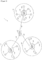
- the wireless network 1 includes a plurality of sub-networks 10, 20, 30 and a network backbone 40.
- the illustrated portion of the network 1 includes three sub-networks, but a skilled technologist will appreciate that the network can include more or less sub-networks.
- Each of the sub-networks 10, 20, 30 includes an access point 110, 120, 130 and one or more wireless stations or devices 111-114, 121-126, 131-134.
- Each of the access points 110-130 is capable of performing wireless communication with the one or more wireless stations within the sub-network according to a wireless communication protocol.
- the access points 110-130 are also connected to the network backbone 40 via wired or wireless channels 50.
- Each of the access points 110-130 may provide communication between stations within its respective sub-network 10-30 or between a station in its sub-network and another station in another sub-network.
- the term "access point" can also be referred to as a "coordinator" in this document.
- a network including such an access point can be referred to as an infrastructure network.
- an access point and non-access point stations in communication with the access point can be collectively referred to as a basic service set.
- the one or more wireless stations 111-114, 121-126, 131-134 are located within a coverage region within which the access point can communicate wirelessly.
- the one or more stations 111-114, 121-126, 131-134 can be electronic devices that can wirelessly connect to one or more of the access points 110, 120, 130.
- Examples of such electronic devices include, but are not limited to, a mobile phone, a smart phone, a telephone, a television, a set-top box, a computer monitor, a computer, a hand-held computer, an electronic book device, a personal digital assistant (PDA), a microwave, a refrigerator, a stereo system, a cassette recorder or player, a DVD player or recorder, a CD player or recorder, a VCR, a digital video recorder (DVR), an MP3 player, a radio, a camcorder, a camera, a digital camera, a portable memory chip, a washer, a dryer, a washer/dryer, a copier, a facsimile machine, a scanner, a multi functional peripheral device, a wrist watch, a clock, a game device, etc.
- one or more stations can belong to two or more sub-networks.
- at least one of the access points 110, 120, 130 may be part of such an electronic device.
- the network backbone 40 serves to interconnect the sub-networks 10, 20, 30 to one another, providing a path for the exchange of information between them.
- the network backbone 40 can be connected to another backbone for communication with another network.
- the sub-networks 110-130 may be in compliance with the same communication protocol. In other embodiments, one of the sub-networks 110-130 may comply with a communication protocol different from the protocols of the other sub-networks. In some embodiments, the sub-networks 110-130 can use different frequency bands from one another. In certain arrangements, the access points and the stations may be in compliance with the IEEE 802.11 standard. In one embodiment, the network 1 can form a wide area network (WAN), and each of the sub-networks 10-30 can form a local area network (LAN). In another embodiment, the network 1 can form a local area network (LAN). In certain embodiments, at least one of the sub-networks 110-130 may form an ad-hoc network without an access point.
- WAN wide area network
- LAN local area network
- at least one of the sub-networks 110-130 may form an ad-hoc network without an access point.
- a wireless station or device can use multiple channels for transmission and/or reception of data or control signals.
- a wireless station or device can be referred to as a multi-band station or device in the context of this document.
- the term "channel" can be interchangeably used with "band,” "frequency band,” or “frequency.”
- the multiple channels can include two or more channels, including, but not limited to, 2.4/5 GHz (for example, in current WiFi), 60 GHz, Bluetooth band (2.4 GHz), and Terahertz.
- a wireless station can use two channels: a high-rate channel (HRC) and a low-rate channel (LRC) for transmission and/or reception.
- HRC high-rate channel
- LRC low-rate channel
- high-rate channel can be interchangeably used with “high frequency channel,” “high frequency band,” “high-rate band,” or “high band” in this document.
- low-rate channel can be interchangeably used with “low frequency channel,” “low frequency band,” “low-rate band,” or “low band” in this document.
- the high-rate channel has a shorter range than the low-rate channel.
- the high-rate channel may be directional whereas the low-rate channel may be directional or omni-directional.
- the low rate channel may be omni-directional as a default, and optionally directional.
- the channels can be established to be directional or omni-directional by using different antenna systems.
- the terms "directional channel” and “omni-directional channel” can be interchangeably used with “directional transmission/reception capability” and “omni-directional transmission/reception capability,” respectively.
- the high-rate channel may have a frequency from about 6 GHz to about 300 GHz. Such a frequency may include an extremely high frequency (EHF).
- the high-rate channel may be a 60 GHz channel that is supported by 60 GHz millimeter-wave radio.
- the communication range of a 60GHz channel for an indoor environment may be of the order of 10 meters.
- the high-rate channel can use a terahertz frequency ranging between 300 GHz and 3 THz.
- the low-rate channel may be a channel having a frequency below 6 GHz.
- the low-rate channel can be a 2.4 GHz or 5 GHz channel that can support Wireless Local Area Network (WLAN).
- the interface for the low-rate channel may be in compliance with IEEE 802.11.
- the low-rate channel for an indoor environment that has a frequency lower than 6 GHz can have a range of about 20 meters to about 100 meters.
- a multi-band station can be part of multiple infrastructure networks that use channels of different frequencies. Referring to Figure 2 , one embodiment of such multiple infrastructure networks will be described below.
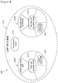
- the illustrated wireless system 200 includes a low-rate (LR) infrastructure network 210, a first high-rate (HR) infrastructure network 220a, and a second high-rate (HR) infrastructure network 220b.
- LR low-rate
- HR high-rate
- HR high-rate
- the LR network 210 overlaps with the first HR network 220a and the second HR network 220b. Because the LR network 210 uses a lower rate channel than the HR networks 220a, 220b in data or control signal transmissions, the LR network 210 has a greater coverage than the HR networks 220a, 220b. The first and second HR networks 220a, 220b do not overlap with each other due to a distance between them.
- the LR network 210 can include a low-rate (LR) access point 215.
- the first and second HR networks 220a, 220b can include first and second high-rate (HR) access points, respectively.
- the first HR access point 225a may also be referred to as a first personal basic service set (PBSS) control point (PCP) in the context of this document.
- the second HR access point 225b may also be referred to as a second personal basic service set (PBSS) control point (PCP) in the context of this document.
- PBSS personal basic service set
- the system 200 can also include a first multi-band station 230 and a second multi-band station 240.
- the first multi-band station 230 is associated with the low-rate access point 215, and thus is part of the LR network 210 when using a low-rate channel.
- the first multi-band station 230 is also associated with the first high-rate access point 225a, and thus is part of the first HR network 220a when using a high-rate channel.
- the second multi-band station 240 is also associated with the low-rate access point 215, and thus is part of the LR network 210 when using the low-rate channel.
- the second multi-band station 240 is also associated with the second high-rate access point 225b, and thus is part of the second HR network 220b when using the high-rate channel.
- the LR network 210 that includes devices using the low-rate channel (for example, the LR access point 215, the first station 230, and the second station 240) can be referred to as a low-rate basic service set (LRBSS).
- the first HR network 220a that includes devices using the high-rate channel (for example, the first HR access point 225a and the first station 230) can be referred to as a first high-rate basic service set (HRBSS1).
- the second HR network 220b that includes devices using the same high-rate channel as the first high-rate network 220a (for example, the second HR access point 225b and the second station 240) can be referred to as a second high-rate basic service set (HRBSS2).
- HRBSS2 second high-rate basic service set
- the LR access point 215 can communicate with either or both of the first and second stations 230, 240 via the low-rate channel.
- the first and second stations 230, 240 can start communication with the LR access point 215 by performing an association process.
- the low-rate access point 215 can transmit low-rate beacon signals periodically to inform a transmission schedule that can be used by devices within the network 210.
- association can refer to a process to establish a link between an access point and a non-access point station or between non-access point stations.
- the association process allows a non-access point station to join in a network.
- the association process can include exchange of an association request and an association response between an access point and a non-access point station.
- the association process can also include authentication of devices involved in the process.
- an association process for the high-rate channel can include beamforming for directional transmission.
- the association process can refer to a process for establishing a link between two non-access point stations, which can involve exchange of control frames, beamforming, and/or authentication.
- the first and second stations 230, 240 can communicate with each other on the low-rate channel via the LR access point 215. In another embodiment, the first and second stations 230, 240 can communicate directly with each other on the low-rate channel via a direct link or a peer-to-peer link, without using the LR access point 215.
- the first HR access point 225a can transmit first beacon signals periodically to inform a transmission schedule that can be used by devices within its network 220a.
- the first beacon signals are transmitted over the high-rate channel, and can be directional.
- the first beacon signals can also be used by devices to determine whether the devices are within the coverage of the first HR network 220a. If it is determined that the devices are within the coverage of the first HR network 220a, such devices can start communication with the first HR access point 225a by performing an association process. Devices that have been associated with the first HR access point 225a can communicate with each other on the high-rate channel, either via the first HR access point 225a or directly.
- the second HR access point 225b can transmit second beacon signals periodically to inform a transmission schedule that can be used by devices within its network 220b.
- the second beacon signals are transmitted over the high-rate channel, and can be directional.
- the second beacon signals can include different information from the first beacon signals, and can be used by devices to determine whether the devices are within the coverage of the second HR network 220b. If it is determined that the devices are within the coverage of the second HR network 220b, such devices can start communication with the second HR access point 225b by performing an association process. Devices that have been associated with the second HR access point 225b can communicate with each other on the high-rate channel, either via the second HR access point 225b or directly.
- the first station 230 is within the coverage of the first HR basic service set 220a, and is associated with the first HR access point 225a.
- the second station 240 is within the coverage of the second HR basic service set 220b, and is associated with the second HR access point 225b.
- the multi-band stations 230, 240 may operate in a distributed mode without being associated with the first or second HR access points 225a, 225b.
- the first and second stations 230, 240 can communicate with each other over the low-rate channel, but not over the high-rate channel due to a distance between them. However, when either or both of the first and second stations 230, 240 are relocated close enough to each other to allow communication over the high-rate channel, they can also communicate over the high-rate channel.
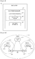
- the illustrated wireless station 300 may serve as a transmitter.
- the wireless station 300 can include an application layer 310, a medium access control (MAC) layer 320, and a physical (PHY) layer 330, and a first antenna system 342, and a second antenna system 344.
- MAC medium access control
- PHY physical
- the application layer 310 may include a data pre-processing module 312 and a data control module 314.
- the data pre-processing module 312 can perform pre-processing of data, such as partitioning of data.
- the data control module 314 provides a standard way to exchange data handling information such as capability information. For example, before a connection begins, the data control module 314 negotiates the data formats to be used, and when the need for the connection is completed, data control commands are used to stop the connection.
- the MAC layer 320 may include a control plane 322, a management plane 324, a high-rate data plane 326, and a low-rate data plane 328.
- the control plane 322 serves to control how the station 300 gains access to data and permission to transmit it over the network.
- at least one of the control plane 322 can include a high-rate control plane and a low-rate control plane to provide access control over the high-rate channel and the low-rate channel, respectively.
- the management plane 324 can include a high-rate management plane and a low-rate management plane to provide channel management over the high-rate channel and the low-rate channel, respectively.
- the high-rate data plane 326 serves to process data from the application layer 310 to form packets suitable for high-rate transmission over a high-rate channel 352.
- the low-rate data plane 328 serves to process data from the application layer 310 to form packets suitable for low-rate transmission over a low-rate channel 354.
- both the high rate data plane 326 and the low rate data plane 328 may use the control plane 322 and the management plane 324 when transmitting data.
- each of the high rate data plane 326 and the low rate data plane 328 can include dedicated control and management planes.
- the PHY layer 330 serves to further process the data and/or control packets from the MAC layer 320, and send them over wireless channels.
- the illustrated PHY layer 330 includes a high-rate (HR) PHY module 332 and a low-rate (LR) PHY module 334.
- the high-rate PHY module 332 adds PHY headers to data packets, and sends the packets over the high-rate channel 352 via the first antenna system 342.
- the first antenna system 342 may be capable of directional transmission and/or reception.
- the low-rate PHY module 332 adds PHY headers to control or data packets from the MAC layer 320, and sends the packets over the low-rate channel 354 via the second antenna system 344.
- the second antenna system may be capable of omni-directional and/or directional transmission and/or reception.
- the second antenna system 344 is configured to perform omni-directional transmission/reception as a default and to optionally provide directional transmission/reception.
- the illustrated wireless station 300 may serve as a receiver.
- the application layer 310, the MAC layer 320, and the PHY layer 330 of the station 300 can perform an inverse processing method of the layers 310-330 to regenerate data from data packets transmitted from another station over the wireless channels.
- a skilled technologist will appreciate that the configuration of the station can vary widely, depending on the design of the station as long as the station can send data and control information via a high rate channel and a low-rate channel, as described above.
- the illustrated MAC layer 320 can also include a multi-band manager 400 in addition to one or more of the components 322, 324, 326, 328 of the MAC layer 320 of Figure 3 .
- the multi-band manager 400 serves to manage use of multiple bands, based at least partly on multi-band information 430.
- the multi-band information 430 can be stored in a storage device (for example, a memory, a solid state disk, and/or a hard disk) of the multi-band station itself. At least part of the multi-band information 430 can be provided and updated by the multi-band station. In addition, at least part of the multi-band information 430 can be provided and updated by another wireless station or an access point.
- access points and/or non-access point wireless stations can periodically switch between an active mode and an inactive mode for saving power.
- active mode can also be referred to as an "awake mode” or “normal mode.”
- inactive mode can also be referred to as a “sleep mode,” “doze mode,” or “power saving mode.”
- Each of such access points and non-access point stations can have a wake-up cycle or schedule.
- the multi-band information 430 can also include information on the wake-up cycle or schedule of one or more of the access points and non-access point stations.
- the multi-band manager 400 can include a fast session transfer module 410 and a wake-up cycle monitor module 420.
- the wake-up cycle monitor module 420 can monitor the wake-up cycle or schedule of its own and one or more of the access points and other non-access point stations on one or more of the multiple bands, based at least partly on the multi-band information 430.
- Other details of the operation of the multi-band station including the wake-up cycle monitor module 420 will be described below in connection with Figures 5A-9 .
- the fast session transfer module 410 can switch transmission between the multiple bands, based at least partly on the availability of the bands and the wake-up cycle or schedule of an access point and/or another wireless station. For example, while the first station 230 ( Figure 2 ) is using the low-rate band in communication with the second station 240 ( Figure 2 ), the first station 230 can switch to the high-rate band if the high-rate band is available for communication with the second station 240 and the second station 240 is awake.
- the modules 410, 420 can be implemented using various software and/or hardware components, not limited to those shown in Figure 4 .
- the LR access point 215 of Figure 2 can include an application layer, a MAC layer, and a PHY layer which are configured to process, send, and receive signals over the low-rate channel.
- Each of the HR access points 225a, 225b of Figure 2 can include an application layer, a MAC layer, and a PHY layer which are configured to process, send, and receive signals over the high-rate channel.
- a skilled technologist will appreciate that various configurations of access points can be adapted for use as the LR access point 215 and the HR access points 225a, 225b.
- a multi-band wireless system can include multi-band wireless stations, each of which can use multiple bands for wireless communication with another station. Because the multiple bands may have different characteristics (for example, coverage and signal strength) from one another, the multi-band wireless stations may be in a situation to be able to use some of the multiple bands, but not other bands, for wireless communication at a given time.
- the stations can be associated with each other via one of available bands, and use the band for communication between the stations.
- the stations can be associated with each other over a low frequency band.
- a band which multi-band stations are currently using for communication between them can be referred to as an "associated band.”
- a band which multi-band stations are not currently using for communication between them can be referred to as an "unassociated band.”
- an unassociated band for example, a higher frequency band
- two or more multi-band wireless stations can form a link or connection for communication by associating with each other on a first (associated) band of multiple bands.
- the multi-band wireless stations can exchange information of a second (unassociated) band on which no link is currently established between the stations. The exchange of the information can be performed on the first (associated) band. Based on the exchanged information, the stations can determine whether the second (unassociated) band is now available for data transmission between them, and can switch to the second band if the second band is available.
- access points and/or non-access point wireless stations can periodically switch between awake mode and sleep mode on one or more wake-up schedules for saving power.
- access points and/or non-access point stations in a multi-band wireless system can use such a power saving scheme with wake-up schedules different from one another.
- each of the access point and the stations can have independent wake-up schedules on the multiple bands that it can use.
- either or both of the two devices may be in sleep mode on a second (unassociated) band.
- two multi-band stations which have formed a link therebetween on a low-frequency band, can be active on the low-frequency band while either or both of the stations are in sleep mode on a highfrequency band.
- an attempt by a station to associate with an access point in sleep mode or to establish a link with another station in sleep mode on the unassociated band would be unsuccessful.
- the station without having information on the wake-up schedules of the access point and/or the other station, the station needs to make multiple attempts until it can successfully communicate with the access point or the other station in awake mode. This would not only take long time, but also waste power, thereby adversely affecting the performance of the station.
- non-access point wireless stations in a multi-band wireless system share information on the wake-up schedules on an unassociated band of an access point and/or the non-access point stations in the system, using an associated band.
- the access point on the unassociated band may also share such information with the non-access point stations.
- the non-access point wireless stations can share information on the awake windows on an unassociated band of the non-access point stations in the system, using an associated band. The non-access point stations can share such information with one another.
- the access point on an unassociated band can adjust its wake-up duty cycle on the unassociated band for facilitating association with one or more stations. Some of the wireless stations can also adjust their wake-up duty cycles on an unassociated band for facilitating setting up a link between the stations. Further, some of the wireless stations can adjust their awake windows on an unassociated band for facilitating setting up a link between the stations. These schemes allow the stations in the multi-band wireless system to effectively and quickly associate with an access point and to establish a link therebetween, thereby saving power.
- a method of wireless communication between multi-band stations in multi-band networks will be described below.
- a first multi-band station 230 and a second multi-band station 240 are within the range of a low-rate network 210.
- Both of the first and second stations 230 have performed an association process with a low-rate (LR) access point 215, and are now connected to the LR access point 215 on a low-rate band (or channel).
- LRBSS low-rate basic service set
- the first station 230 is within the range of a first high-rate network 220a, and the second station 240 is within the range of a second high-rate network 220b.
- the first station 230 has performed an association process with a first high-rate (HR) access point 225a, and is now connected to the first HR access point 225a on a high-rate band (or channel).
- HR high-rate
- a network may also be referred to as a first high-rate basic service set (HRBSS1).
- the second station 240 has performed an association process with a second high-rate (HR) access point 225b, and is now connected to the second HR access point 225b on the same high-rate band (or channel) as that of the first high-rate basic service set (HRBSS1).
- HRBSS1 high-rate basic service set
- HRBSS2 second high-rate basic service set
- Other details of the access points 215, 225a, 225b, and the stations 230, 240 can be as described above in connection with Figure 2 .
- the first and second stations 230, 240 cannot communicate with each other over the high-rate band. However, both the first and second stations 230, 240 are associated with the LR access point 215 on the low-rate band, and thus the first and second stations 230, 240 can establish a link on the low-rate band.
- the link may be, for example, a peer-to-peer (P2P) link or a direct link specified under IEEE 802.11 standard.
- P2P peer-to-peer
- direct link refers to a bidirectional link from one non-access point (non-AP) quality of service (QoS) station to another non-AP QoS station operating in the same infrastructure QoS basic service set (BSS) that does not pass through a QoS access point.
- QoS quality of service
- BSS infrastructure QoS basic service set
- a band which multi-band stations are currently using for communication between them can be referred to as an "associated band.”
- the low-rate band in Figure 5A can be an associated band.
- a band which multi-band stations are not currently using for communication between them can be referred to as an "unassociated band.”
- the high-rate band in Figure 5A can be an unassociated band.
- a band may not be used for communication between multi-band stations for various reasons, including, but not limited to: an inferior link quality (for example, Bit Error Rate (BER), Signal to Interference and Noise Ratio (SINR), Received Signal Strength Indication (RSSI), and the like), a lower data rate, a lower effective available time due to a higher channel load, a different awake schedule, and distance separation.
- an inferior link quality for example, Bit Error Rate (BER), Signal to Interference and Noise Ratio (SINR), Received Signal Strength Indication (RSSI), and the like
- BER Bit Error Rate
- SINR Signal to Interference and Noise Ratio
- RSSI Received Signal Strength Indication
- each of the first and second high-rate access points 225a, 225b, the first station 230, and the second station 240 can periodically switch between awake mode and sleep mode on a wake-up schedule.
- One or more of the first and second high-rate access points 225a, 225b, the first station 230, and the second station 240 can have a different wake-up schedule on the high-rate band from the others.
- the first and second stations 230, 240 can exchange information on the status of the unassociated (high-rate) band over the associated (low-rate) band.
- the information can include information on the wake-up schedules on the unassociated (high-rate) band of the high-rate access points 225a, 225b, the first station 230, and the second station 240. Details of the information will be described below in connection with Figures 6 , 7A and 7B .
- the information on the wake-up schedules can be periodically generated and transmitted on the low-rate (used) band between the stations 230, 240.
- the information can be generated and transmitted by one of the stations 230, 240 upon a request by the other of the stations 230, 240.
- the information can be transmitted between the stations 230, 240 when there is a change in the information.
- the information can be transmitted between the stations 230, 240 only when there is a change in the information. In such embodiments, less power is consumed by the stations than when the status is periodically transmitted.
- the first station 230 has moved closer to the second HR access point 225b such that the first station 230 is within the range of the second HR network 220b and is no longer within the range of the first HR network 220a.
- the first station 230 can now successfully associate with the second high-rate access point 225b during an awake period of the second HR access point 225b, based at least partly on the information on the wake-up schedule of the second HR access point 225b.
- the first station 230 can avoid attempting to associate with the second HR access point 225b while the access point 225b is inactive, thereby preventing waste of power.
- the first station 230 can send the second station 240 a request to establish a link on the unassociated (high-rate) band with the second station during an awake period of the second station 230, based at least partly on the information on the wake-up schedule of the second station 240.
- the first station 230 can avoid attempting to establish a link with the second station 240 while the second station 240 is inactive, thereby preventing waste of power.
- the link between the first and second stations 230, 240 can be a direct link.
- the link between the first and second stations 230, 240 can be established via the low-rate access point 215.
- either or both of the stations 230, 240 can determine if a session transfer from the low-rate band to the high-rate band can be triggered. The determination can be based at least partly on, for instance, whether it may be more efficient to change the transmission channel. Efficiency of the transmission can be determined by the multi-band manager, based on various factors (for example, the beacon quality from the new unassociated BSS meets the acceptable SNR limit). In one embodiment, this process can be performed at least partly by the multi-band manager of the station 230, 240, as shown in Figure 4 . After the session transfer is completed, the first and second stations 230, 240 can use the link for data communication between them, as shown in Figure 5D .
- awake beacons and non-awake beacons are alternately transmitted at a selected interval from an access point on one of multiple bands that the multi-band device can use.
- the awake beacons are transmitted at, for example, t2, t4, and t6 in Figure 6 .
- the non-awake Target Beacon Transmission Time (TBTT) occurs at, for example, t3 and t5 in Figure 6 .
- the non-awake TBTTs may not have beacons present when the access point is in sleep mode as well.
- the multi-band station can switch between awake mode and sleep mode.
- the multi-band station when it has a 50% awake period duty cycle (more details on the awake period duty cycle will be described later), can be in awake mode between an awake beacon and an immediately following non-awake beacon, and in sleep mode between a non-awake beacon and an immediately following awake beacon.
- the multi-band wireless device can transmit a wake-up schedule information element 601 on an associated band to an access point and/or other stations on the associated band.
- the wake-up schedule information element 601 can be transmitted during a time period between t0 and t1.
- the wake-up schedule information element 601 can include information on the wake-up schedules of the unassociated band of the multi-band station itself or an access point with which the multi-band station is associated.
- the second station 240 can transmit a wake-up schedule information element on the low-rate band.
- the information element can include the wake-up schedules of the second station 240 itself and/or the second high-rate access point 225b.
- the wake-up schedule information element 601 can include information on the start time of a wake-up schedule on an unassociated band.
- the start time can be t2.
- the wake-up schedule information element 601 can also include information on a sleep interval, which represents a time difference between the starting points in time of two successive awake windows or a duration of one cycle of awake mode and sleep mode.
- the sleep interval can be a time difference between t2 and t4.
- the wake-up schedule information element 601 can further include information on an awake window on the unassociated band.
- the awake window can be between t2 and t23.
- other stations can perform contention-based communication with the multi-band station on the unassociated band.
- a time period between t2 and t3 can be referred to as an awake period.
- an awake window (t2 to t23) is shown to be shorter than the awake period (t2 to t3).
- the length of the awake period and awake window can be substantially the same as each other, i.e., the awake period and awake window substantially fully overlap with each other.
- Other details of the wake-up schedule information element 601 will be described below in connection with Figures 7A and 7B .
- the wake-up schedule information element can be part of any suitable control frame exchanged between multi-band wireless devices.
- the wake-up schedule information element can include information on wake-up schedules and/or awake window, as described above in connection with Figure 6 .
- an information element can include information on the awake window of the multi-band station.
- the illustrated information element 700A includes an element ID field 710a, a length field 720a, and an awake window field 730a.
- the element ID field 710a includes information indicative of the identifier of the information element 700A, and is one octet long.
- the length field 720a indicates the length of the information element 700A, and is one octet long.
- the awake window field 730a includes the length of the awake window measured in microsecond, and is two octets long.
- an information element can include information on the wake-up schedules of a multi-band station.
- the illustrated information element 700B includes an element ID field 710b, a length field 720b, a start time field 740b, and a sleep interval field 750b.
- the element ID field 710b includes information indicative of the identifier of the information element 700B, and is one octet long.
- the length field 720b indicates the length of the information element 700B, and is one octet long.
- the start time field 740b can be 4 octets long.
- the start time field 740b can indicate anticipated start time, expressed in microseconds, from the end of transmission of the information element to a first awake beacon.
- the start time field 740b can include a value that represents the lower order 4 octets of a timing synchronization function (TSF) timer value at the start of the first awake beacon.
- TSF timing synchronization function
- Timing synchronization function refers to a function that keeps the timers for all stations in the same basic service set synchronized.
- An example of the TSF timer is specified in IEEE 802.11 standard.
- the start time field 740b can indicate start time, expressed in microseconds, of a first non-awake beacon interval.
- the start time field 740b can include a value that represents the lower order 4 octets of a TSF timer value at the start of the first non-awake beacon interval.
- the sleep interval field 750b can be 2 octets long.
- the sleep interval field 750b indicates time, expressed in number of target beacon transmission times (TBTTs), between two successive awake beacons.
- the sleep interval field 750b indicates the length of the access point sleep interval, expressed in number of TBTTs.
- an information element can include information on both the awake window of the multi-band station and the wake-up schedules of the station and its access point on the unassociated band.
- the information element can include an element ID field, a length field, an awake window field, a start time field, and a sleep interval field. Details of these fields can be as described above in connection with Figures 7A and 7B .
- Figure 8 is a timing diagram illustrating one example of wake-up cycles on an unassociated (high-rate) band of the second high-rate access point 225b, the first station 230, and the second station 240 of Figures 5A-5D .
- the second station 240 is associated with the second high-rate access point 225b.
- the first station 230 is associated with the first high-rate (HR) access point 225a at first, as shown in Figure 5A .
- the first station 230 can move close to the second HR access point 225b, as shown in Figure 5B .
- each of the first and second stations 230, 240 can share and monitor the wake-up cycle or schedule of its own and one or more of the access points and other non-access point stations, as described above in connection with Figures 4 and 5A .
- the second high-rate access point 225b transmits awake beacons AB1-AB5 and non-awake beacons NB1-NB5 at a selected interval.
- the second high-rate access point 225b can alternately transmit the beacons AB1-AB5 and NB1-NB5 at t0, t1, t2, ..., t9.
- the second high-rate access point 225 is awake during awake periods 801, for example, between t0 and t1, between t2 and t3, between t4 and t5, between t6 and t7, and between t8 and t9.
- t1, t3, t5, t7, and t9 are at a midpoint between t0 and t2, between t2 and t4, between t4 and t6, between t6 and t8 and between t8 and t10 (not shown), respectively.
- the second high-rate access point 225b has an awake period duty cycle of 50%.
- the term "awake period duty cycle” refers to a ratio of an awake period duration to a sleep interval.
- the sleep interval is a period between the starting points in time of two immediately succeeding awake periods. With respect to the second high-rate access point in Figure 6 , it can be calculated from, for example, "(t1-t0)/(t2-t0) ⁇ 100.”
- the second station 240 is awake during awake periods 811, for example, between t0 and t1, between t4 and t5, and between t8 and t9.
- the second station 240 has an awake period duty cycle of 25%, which can be calculated from, for example, ⁇ t 1 ⁇ t 0 / t 4 ⁇ t 0 ⁇ 100. ′′
- the second station 240 has an awake window during each of its awake period.
- the awake window starts at the starting point in time of the awake period, and ends before the ending point in time of the awake period.
- a first awake window 821 starts at t0 and ends at t01 which is between t0 and t1.
- a second awake window 822 starts at t4 and ends at t45 which is between t4 and t5.
- a third awake window 823 starts at t8 and ends at t89 which is between t8 and t9.
- the first station 230 can have its own wake-up schedule that is not synchronized with the wake-up schedules of the second station 240 and/or the second high-rate access point 225b. For example, the first station 230 can have awake periods 831a, based on its wake-up schedule. However, the first station 230 can also have information on the wake-up schedules of the second station 240 and/or the second high-rate access point 225b by receiving wake-up schedule information elements.
- the first station 230 can adjust its wake-up schedule, based at least partly on the wake-up schedule of the second high-rate access point 225b. For example, the first station 230 can have adjusted awake periods 831b that are at least partially synchronized with the awake periods 801, 811 of the second station 240 and/or the second high-rate access point 225b.
- the first station 230 can attempt to associate with the second high-rate access point 225b during an awake period 801 of the second high-rate access point 225b. For example, the first station 230 can initiate an association process with the second high-rate access point 225b between t4 and t5.
- the first station 230 can also attempt to establish a link with the second station 240 during an awake window of the second station 240. For example, the first station 230 can attempt to set up a link with the second station 240 during a next available awake window of the second station 240, for example, the third awake window 823. When setting up such a link, the first station 230 can transmit a control frame to request for setting up, for example, a direct link. In one embodiment, the control frame can be an ad-hoc traffic indication message (ATIM). In another embodiment, the first station 230 can establish a link with the second station 240 via the second high-rate access point 225b. In other embodiments, the first station 230 can establish a link with the second station 240 without first associating with the high-rate access point 225b.
- ATIM ad-hoc traffic indication message
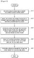
- the illustrated process can be performed by a station (for example, the first station 230 of Figures 5A-5D ) moving close to a new access point (for example, the second high-rate access point 225b of Figures 5A-5D ) on an unassociated band (for example, a high-rate band).
- the access point can be associated with another wireless station (for example, the second station 240 of Figures 5A-5D ) on the unassociated band.
- the other station can have a pre-established link with the station on an associated band (for example, a low-rate band).
- the first station 230 can receive a wake-up schedule information element including information on the associated band.
- the information can include the wake-up schedules of the second high-rate access point 225b and the second station 240 and the awake window of the second station 240.
- the first station 230 can wake up immediately before or during an awake period on the unassociated band of the second high-rate access point 225b, based at least partly on the wake-up schedule of the second high-rate access point 225b.
- the first station 230 can receive a beacon signal on the unassociated band from the second high-rate access point 225b, and perform an association process with the second high-rate access point 225b during the awake period on the unassociated band. Then, the first station 230 can optionally go into an inactive or sleep mode.
- the first station 230 can wake up immediately before or during an awake period on the unassociated band of the second station 240, based at least partly on information on the awake window of the second station 240.
- the first station 230 can establish a link with the second station 240 by performing an association process during the awake window on the unassociated band.
- the first station 230 and the second station 240 can perform a session transfer from the associated band to the newly associated band. Then, the first and second stations 230, 240 can communicate data with each other on the newly associated band.
- an access point and/or non-access point stations can adjust their wake-up schedules after exchanging wake-up schedule information elements with one another for facilitating association and link formation. For example, after receiving the wake-up schedules of the second high-rate access point 225b and the second station 240 at block 910, the first station 230 can suggest an alternative wake-up schedule on the unassociated band to the second high-rate access point 225b and the second station 240. In response, the second high-rate access point 225b and the second station 240 can adjust their wake-up schedules and/or awake window on the unassociated band. In other embodiments, an access point and/or non-access point stations can adjust their wake-up duty cycles on an unassociated band after exchanging wake-up schedule information elements with one another.
- one or more blocks may be omitted, depending on the design of the system.
- two or more of the blocks may be combined together.
- the methods may include additional blocks, depending on the design of the system.
- the methods of the embodiments described above allow a multi-band station to test the availability of an access point and/or another station without performing unnecessary scanning during their sleep periods.
- the multi-band station can effectively and promptly associate with an access point or the other station on an unassociated band. This also saves power, which is an important resource in most wireless devices, especially mobile devices.
- the embodiments described above may be used for data (e.g., video data and audio data) streaming over a wireless network.
- the embodiments may be adapted for transmission of uncompressed video in a wireless local area network (WLAN) under the IEEE 802.11 standard (for example, IEEE 802.11ad).
- the embodiments can also be adapted for a wireless system having a very high throughput (VHT) of about 0.5 Gbps to about 4 Gbps.
- VHT very high throughput
- the embodiments can be adapted for a standard such as the WiGig standard.
- the embodiments can be adapted for a wireless system having a bandwidth of 60 GHz, while supporting the IEEE 802.11 standard.
Landscapes
- Engineering & Computer Science (AREA)
- Computer Networks & Wireless Communication (AREA)
- Signal Processing (AREA)
- Mobile Radio Communication Systems (AREA)
Description
- The present invention relates to a wireless network, and in particular, to a wireless network having multi-rate channels.
- Wireless networks typically include a plurality of wireless stations. Such wireless stations can communicate with each other on a wireless channel having a selected frequency.
- Certain wireless stations can use multiple channels for transmission and/or reception of signals. For example, a wireless station can use a high-rate channel (for example, 60 GHz channel) and a low-rate channel (2.4/5 GHz channel). Such a wireless station can use either or both of the channels, depending on the needs.
- It is often desirable to use a higher frequency channel among the multiple channels to have a higher transmission rate. However, such a higher frequency channel may not be always available for transmission between two wireless stations at a given time. Thus, there is a need for managing the use of the multiple channels to optimize wireless transmissions between the wireless stations.
-
US 2007/0253391 A1 is background art and discloses a method and system for channel time allocation and access control in wireless networks. - In one embodiment, there is a device for power-saving communication and a method of power-saving communication as set out in the accompanying claims.
-
-
Figure 1 is a block diagram illustrating an example wireless network including a plurality of sub-networks. -
Figure 2 is a block diagram of a wireless network including a low-rate basic service set and high-rate basic service sets according to one embodiment. -
Figure 3 is a block diagram illustrating a multi-band wireless device having high-rate and low-rate communication capabilities according to one embodiment. -
Figure 4 is a block diagram illustrating the MAC layer of the wireless device ofFigure 3 , including a multi-band manager according to one embodiment. -
Figures 5A-5D illustrate a method of wireless communication by multi-band wireless devices according to one embodiment. -
Figure 6 is a timing diagram illustrating a method of wireless communication by a multi-band wireless device transmitting a wake-up information element for wake-up schedules according to one embodiment. -
Figure 7A is a frame format of an information element including information on an awake window according to one embodiment. -
Figure 7B is a frame format of an information element including information on a wake-up schedule according to one embodiment. -
Figure 8 is a timing diagram illustrating a method of wireless communication by multi-band wireless devices operating on wake-up schedules according to one embodiment. -
Figure 9 is a flowchart illustrating a method of wireless communication using a wake-up schedule according to one embodiment. - In one embodiment, there is a device for wireless communication. The device comprises: a first antenna system configured to use a first frequency band for wireless communication; and a second antenna system configured to use a second frequency band for wireless communication. The second frequency band is different from the first frequency band. The device further comprises a memory configured to store information comprising one or more wake-up schedules on the second frequency band of the device and/or other wireless devices; and a medium access control (MAC) layer configured to transmit and/or receive a signal via a pre-established wireless link on the first frequency band, wherein the signal contains at least part of the one or more wake-up schedules.
- In another embodiment, there is a wireless communication system. The system comprises: a first multi-band wireless station that is capable of using a first frequency band and a second frequency band for wireless communication. The second frequency band is different from the first frequency band. The system also comprises a second multi-band wireless station that is capable of using the first frequency band and the second frequency band for wireless communication. One or more of the first and second stations is configured to maintain therein one or more wake-up schedules on the second frequency band of one or more of the first station, the second station, and an access point. The first and second stations are configured to share the one or more wake-up schedules with each other via the first frequency band.
- In yet another embodiment, there is a method of wireless communication. The method comprises: establishing, by a first multi-band wireless station capable of using first and second frequency bands for wireless communication, a wireless link on the first frequency band with a second multi-band wireless station capable of using the first and second frequency bands for wireless communication. The second frequency band is different from the first frequency band. The method also comprises transmitting, by the first station, one or more wake-up schedules on the second frequency band to the second station via the first frequency band. The one or more wake-up schedules comprise a wake-up schedule of the first station and/or an access point. The access point is associated with the first station on the second frequency band.
- In yet another embodiment, there is a method of wireless communication. The method comprises: establishing, by a first multi-band wireless station capable of using first and second frequency bands for wireless communication, a wireless link on the first frequency band with a second multi-band wireless station capable of using the first and second frequency bands for wireless communication. The second frequency band is different from the first frequency band. The method also comprises receiving, by the first station, one or more wake-up schedules on the second frequency band from the second station via the first frequency band. The one or more wake-up schedules comprise a wake-up schedule of the second station and/or an access point. The access point is associated with the second station on the second frequency band.
- The following detailed description of certain embodiments presents various descriptions of specific embodiments of the invention. However, the invention can be embodied in a multitude of different ways as defined and covered by the claims. In this description, reference is made to the drawings where like reference numerals indicate identical or functionally similar elements.
- The terminology used in the description presented herein is not intended to be interpreted in any limited or restrictive manner, simply because it is being utilized in conjunction with a detailed description of certain specific embodiments of the invention. Furthermore, embodiments of the invention may include several novel features, no single one of which is solely responsible for its desirable attributes or which is essential to practicing the inventions herein described. Various processors, memories, computer readable media and programs can be used to implement the invention.
- Referring to
Figure 1 , an example wireless network will be described below. Thewireless network 1 includes a plurality ofsub-networks network backbone 40. The illustrated portion of thenetwork 1 includes three sub-networks, but a skilled technologist will appreciate that the network can include more or less sub-networks. - Each of the
sub-networks access point network backbone 40 via wired orwireless channels 50. Each of the access points 110-130 may provide communication between stations within its respective sub-network 10-30 or between a station in its sub-network and another station in another sub-network. The term "access point" can also be referred to as a "coordinator" in this document. A network including such an access point can be referred to as an infrastructure network. In the context of this document, an access point and non-access point stations in communication with the access point can be collectively referred to as a basic service set. - The one or more wireless stations 111-114, 121-126, 131-134 are located within a coverage region within which the access point can communicate wirelessly. The one or more stations 111-114, 121-126, 131-134 can be electronic devices that can wirelessly connect to one or more of the
access points access points - The
network backbone 40 serves to interconnect thesub-networks network backbone 40 can be connected to another backbone for communication with another network. - In one embodiment, the sub-networks 110-130 may be in compliance with the same communication protocol. In other embodiments, one of the sub-networks 110-130 may comply with a communication protocol different from the protocols of the other sub-networks. In some embodiments, the sub-networks 110-130 can use different frequency bands from one another. In certain arrangements, the access points and the stations may be in compliance with the IEEE 802.11 standard. In one embodiment, the
network 1 can form a wide area network (WAN), and each of the sub-networks 10-30 can form a local area network (LAN). In another embodiment, thenetwork 1 can form a local area network (LAN). In certain embodiments, at least one of the sub-networks 110-130 may form an ad-hoc network without an access point. - In some embodiments, a wireless station or device can use multiple channels for transmission and/or reception of data or control signals. Such a wireless station or device can be referred to as a multi-band station or device in the context of this document. In this document, the term "channel" can be interchangeably used with "band," "frequency band," or "frequency." For example, the multiple channels can include two or more channels, including, but not limited to, 2.4/5 GHz (for example, in current WiFi), 60 GHz, Bluetooth band (2.4 GHz), and Terahertz.
- In one embodiment, a wireless station can use two channels: a high-rate channel (HRC) and a low-rate channel (LRC) for transmission and/or reception. The term "high-rate channel" can be interchangeably used with "high frequency channel," "high frequency band," "high-rate band," or "high band" in this document. The term "low-rate channel" can be interchangeably used with "low frequency channel," "low frequency band," "low-rate band," or "low band" in this document.
- The high-rate channel has a shorter range than the low-rate channel. The high-rate channel may be directional whereas the low-rate channel may be directional or omni-directional. In certain embodiments, the low rate channel may be omni-directional as a default, and optionally directional. The channels can be established to be directional or omni-directional by using different antenna systems. In the context of this document, the terms "directional channel" and "omni-directional channel" can be interchangeably used with "directional transmission/reception capability" and "omni-directional transmission/reception capability," respectively.
- In one embodiment, the high-rate channel may have a frequency from about 6 GHz to about 300 GHz. Such a frequency may include an extremely high frequency (EHF). The high-rate channel may be a 60 GHz channel that is supported by 60 GHz millimeter-wave radio. In one embodiment, the communication range of a 60GHz channel for an indoor environment may be of the order of 10 meters. In other embodiments, the high-rate channel can use a terahertz frequency ranging between 300 GHz and 3 THz.
- The low-rate channel may be a channel having a frequency below 6 GHz. In one embodiment, the low-rate channel can be a 2.4 GHz or 5 GHz channel that can support Wireless Local Area Network (WLAN). The interface for the low-rate channel may be in compliance with IEEE 802.11. In one embodiment, the low-rate channel for an indoor environment that has a frequency lower than 6 GHz can have a range of about 20 meters to about 100 meters.
- In some embodiments, a multi-band station can be part of multiple infrastructure networks that use channels of different frequencies. Referring to
Figure 2 , one embodiment of such multiple infrastructure networks will be described below. The illustratedwireless system 200 includes a low-rate (LR)infrastructure network 210, a first high-rate (HR)infrastructure network 220a, and a second high-rate (HR)infrastructure network 220b. - The
LR network 210 overlaps with thefirst HR network 220a and thesecond HR network 220b. Because theLR network 210 uses a lower rate channel than theHR networks LR network 210 has a greater coverage than theHR networks second HR networks LR network 210 can include a low-rate (LR)access point 215. The first andsecond HR networks HR access point 225a may also be referred to as a first personal basic service set (PBSS) control point (PCP) in the context of this document. The secondHR access point 225b may also be referred to as a second personal basic service set (PBSS) control point (PCP) in the context of this document. - The
system 200 can also include a firstmulti-band station 230 and a secondmulti-band station 240. In the illustrated instance, the firstmulti-band station 230 is associated with the low-rate access point 215, and thus is part of theLR network 210 when using a low-rate channel. The firstmulti-band station 230 is also associated with the first high-rate access point 225a, and thus is part of thefirst HR network 220a when using a high-rate channel. The secondmulti-band station 240 is also associated with the low-rate access point 215, and thus is part of theLR network 210 when using the low-rate channel. The secondmulti-band station 240 is also associated with the second high-rate access point 225b, and thus is part of thesecond HR network 220b when using the high-rate channel. - In the embodiment shown in
Figure 2 , theLR network 210 that includes devices using the low-rate channel (for example, theLR access point 215, thefirst station 230, and the second station 240) can be referred to as a low-rate basic service set (LRBSS). Thefirst HR network 220a that includes devices using the high-rate channel (for example, the firstHR access point 225a and the first station 230) can be referred to as a first high-rate basic service set (HRBSS1). Thesecond HR network 220b that includes devices using the same high-rate channel as the first high-rate network 220a (for example, the secondHR access point 225b and the second station 240) can be referred to as a second high-rate basic service set (HRBSS2). - During operation, the
LR access point 215 can communicate with either or both of the first andsecond stations second stations LR access point 215 by performing an association process. In certain embodiments, the low-rate access point 215 can transmit low-rate beacon signals periodically to inform a transmission schedule that can be used by devices within thenetwork 210. - In the context of this document, the term "association" can refer to a process to establish a link between an access point and a non-access point station or between non-access point stations. In one embodiment, the association process allows a non-access point station to join in a network. The association process can include exchange of an association request and an association response between an access point and a non-access point station. The association process can also include authentication of devices involved in the process. In certain embodiments, an association process for the high-rate channel can include beamforming for directional transmission. In other embodiments, the association process can refer to a process for establishing a link between two non-access point stations, which can involve exchange of control frames, beamforming, and/or authentication.
- The first and
second stations LR access point 215. In another embodiment, the first andsecond stations LR access point 215. - In some embodiments, the first
HR access point 225a can transmit first beacon signals periodically to inform a transmission schedule that can be used by devices within itsnetwork 220a. The first beacon signals are transmitted over the high-rate channel, and can be directional. The first beacon signals can also be used by devices to determine whether the devices are within the coverage of thefirst HR network 220a. If it is determined that the devices are within the coverage of thefirst HR network 220a, such devices can start communication with the firstHR access point 225a by performing an association process. Devices that have been associated with the firstHR access point 225a can communicate with each other on the high-rate channel, either via the firstHR access point 225a or directly. - Similarly, the second
HR access point 225b can transmit second beacon signals periodically to inform a transmission schedule that can be used by devices within itsnetwork 220b. The second beacon signals are transmitted over the high-rate channel, and can be directional. The second beacon signals can include different information from the first beacon signals, and can be used by devices to determine whether the devices are within the coverage of thesecond HR network 220b. If it is determined that the devices are within the coverage of thesecond HR network 220b, such devices can start communication with the secondHR access point 225b by performing an association process. Devices that have been associated with the secondHR access point 225b can communicate with each other on the high-rate channel, either via the secondHR access point 225b or directly. - In the illustrated example, the
first station 230 is within the coverage of the first HRbasic service set 220a, and is associated with the firstHR access point 225a. Thesecond station 240 is within the coverage of the second HRbasic service set 220b, and is associated with the secondHR access point 225b. In certain embodiments, themulti-band stations HR access points - In the illustrated example, the first and
second stations second stations - Referring to
Figure 3 , a multi-band wireless station that can communicate with one or more stations or access points via a high-rate channel and a low-rate channel according to one embodiment will be described below. The illustratedwireless station 300 may serve as a transmitter. Thewireless station 300 can include anapplication layer 310, a medium access control (MAC)layer 320, and a physical (PHY)layer 330, and afirst antenna system 342, and asecond antenna system 344. - The
application layer 310 may include adata pre-processing module 312 and adata control module 314. Thedata pre-processing module 312 can perform pre-processing of data, such as partitioning of data. Thedata control module 314 provides a standard way to exchange data handling information such as capability information. For example, before a connection begins, thedata control module 314 negotiates the data formats to be used, and when the need for the connection is completed, data control commands are used to stop the connection. - The
MAC layer 320 may include acontrol plane 322, amanagement plane 324, a high-rate data plane 326, and a low-rate data plane 328. Thecontrol plane 322 serves to control how thestation 300 gains access to data and permission to transmit it over the network. In one embodiment, at least one of thecontrol plane 322 can include a high-rate control plane and a low-rate control plane to provide access control over the high-rate channel and the low-rate channel, respectively. Further, themanagement plane 324 can include a high-rate management plane and a low-rate management plane to provide channel management over the high-rate channel and the low-rate channel, respectively. - The high-
rate data plane 326 serves to process data from theapplication layer 310 to form packets suitable for high-rate transmission over a high-rate channel 352. The low-rate data plane 328 serves to process data from theapplication layer 310 to form packets suitable for low-rate transmission over a low-rate channel 354. In one embodiment, both the highrate data plane 326 and the lowrate data plane 328 may use thecontrol plane 322 and themanagement plane 324 when transmitting data. In other embodiments, each of the highrate data plane 326 and the lowrate data plane 328 can include dedicated control and management planes. - The
PHY layer 330 serves to further process the data and/or control packets from theMAC layer 320, and send them over wireless channels. The illustratedPHY layer 330 includes a high-rate (HR)PHY module 332 and a low-rate (LR)PHY module 334. The high-rate PHY module 332 adds PHY headers to data packets, and sends the packets over the high-rate channel 352 via thefirst antenna system 342. Thefirst antenna system 342 may be capable of directional transmission and/or reception. The low-rate PHY module 332 adds PHY headers to control or data packets from theMAC layer 320, and sends the packets over the low-rate channel 354 via thesecond antenna system 344. The second antenna system may be capable of omni-directional and/or directional transmission and/or reception. In certain embodiments, thesecond antenna system 344 is configured to perform omni-directional transmission/reception as a default and to optionally provide directional transmission/reception. - Alternatively, the illustrated
wireless station 300 may serve as a receiver. When serving as a receiver, theapplication layer 310, theMAC layer 320, and thePHY layer 330 of thestation 300 can perform an inverse processing method of the layers 310-330 to regenerate data from data packets transmitted from another station over the wireless channels. A skilled technologist will appreciate that the configuration of the station can vary widely, depending on the design of the station as long as the station can send data and control information via a high rate channel and a low-rate channel, as described above. - Referring to
Figure 4 , the MAC layer of a multi-band wireless station (for example, the first andsecond stations Figure 2 ) according to one embodiment will be described below. The illustratedMAC layer 320 can also include amulti-band manager 400 in addition to one or more of thecomponents MAC layer 320 ofFigure 3 . - The
multi-band manager 400 serves to manage use of multiple bands, based at least partly onmulti-band information 430. Themulti-band information 430 can be stored in a storage device (for example, a memory, a solid state disk, and/or a hard disk) of the multi-band station itself. At least part of themulti-band information 430 can be provided and updated by the multi-band station. In addition, at least part of themulti-band information 430 can be provided and updated by another wireless station or an access point. - In some embodiments, access points and/or non-access point wireless stations can periodically switch between an active mode and an inactive mode for saving power. The term "active mode" can also be referred to as an "awake mode" or "normal mode." The term "inactive mode" can also be referred to as a "sleep mode," "doze mode," or "power saving mode." Each of such access points and non-access point stations can have a wake-up cycle or schedule. In such embodiments, the
multi-band information 430 can also include information on the wake-up cycle or schedule of one or more of the access points and non-access point stations. - In the illustrated embodiment, the
multi-band manager 400 can include a fastsession transfer module 410 and a wake-upcycle monitor module 420. The wake-upcycle monitor module 420 can monitor the wake-up cycle or schedule of its own and one or more of the access points and other non-access point stations on one or more of the multiple bands, based at least partly on themulti-band information 430. Other details of the operation of the multi-band station including the wake-upcycle monitor module 420 will be described below in connection withFigures 5A-9 . - The fast
session transfer module 410 can switch transmission between the multiple bands, based at least partly on the availability of the bands and the wake-up cycle or schedule of an access point and/or another wireless station. For example, while the first station 230 (Figure 2 ) is using the low-rate band in communication with the second station 240 (Figure 2 ), thefirst station 230 can switch to the high-rate band if the high-rate band is available for communication with thesecond station 240 and thesecond station 240 is awake. A skilled technologist will appreciate that themodules Figure 4 . - In one embodiment, the
LR access point 215 ofFigure 2 can include an application layer, a MAC layer, and a PHY layer which are configured to process, send, and receive signals over the low-rate channel. Each of theHR access points Figure 2 can include an application layer, a MAC layer, and a PHY layer which are configured to process, send, and receive signals over the high-rate channel. A skilled technologist will appreciate that various configurations of access points can be adapted for use as theLR access point 215 and theHR access points - A multi-band wireless system can include multi-band wireless stations, each of which can use multiple bands for wireless communication with another station. Because the multiple bands may have different characteristics (for example, coverage and signal strength) from one another, the multi-band wireless stations may be in a situation to be able to use some of the multiple bands, but not other bands, for wireless communication at a given time.
- In such an instance, the stations can be associated with each other via one of available bands, and use the band for communication between the stations. For example, the stations can be associated with each other over a low frequency band. In the context of this document, a band which multi-band stations are currently using for communication between them can be referred to as an "associated band." On the other hand, a band which multi-band stations are not currently using for communication between them can be referred to as an "unassociated band." However, it may be desirable to use an unassociated band (for example, a higher frequency band) for faster data transmission when the unassociated band becomes available. Thus, there is a need for keeping track of the status and/or availability of the multiple bands.
- In one embodiment, two or more multi-band wireless stations can form a link or connection for communication by associating with each other on a first (associated) band of multiple bands. The multi-band wireless stations can exchange information of a second (unassociated) band on which no link is currently established between the stations. The exchange of the information can be performed on the first (associated) band. Based on the exchanged information, the stations can determine whether the second (unassociated) band is now available for data transmission between them, and can switch to the second band if the second band is available.
- In some embodiments, access points and/or non-access point wireless stations can periodically switch between awake mode and sleep mode on one or more wake-up schedules for saving power. In certain embodiments, access points and/or non-access point stations in a multi-band wireless system (for example, the
system 200 ofFigure 2 ) can use such a power saving scheme with wake-up schedules different from one another. In addition, each of the access point and the stations can have independent wake-up schedules on the multiple bands that it can use. - In such embodiments, after any two of the access point and the stations establish a link on a first (associated) band, either or both of the two devices may be in sleep mode on a second (unassociated) band. For example, two multi-band stations, which have formed a link therebetween on a low-frequency band, can be active on the low-frequency band while either or both of the stations are in sleep mode on a highfrequency band. In such an instance, an attempt by a station to associate with an access point in sleep mode or to establish a link with another station in sleep mode on the unassociated band would be unsuccessful. In addition, without having information on the wake-up schedules of the access point and/or the other station, the station needs to make multiple attempts until it can successfully communicate with the access point or the other station in awake mode. This would not only take long time, but also waste power, thereby adversely affecting the performance of the station. Thus, there is a need for exchanging information on the wake-up schedules in advance between the stations in a multi-band wireless system.
- In one embodiment, non-access point wireless stations in a multi-band wireless system share information on the wake-up schedules on an unassociated band of an access point and/or the non-access point stations in the system, using an associated band. In addition, the access point on the unassociated band may also share such information with the non-access point stations. In another embodiment, the non-access point wireless stations can share information on the awake windows on an unassociated band of the non-access point stations in the system, using an associated band. The non-access point stations can share such information with one another.
- In some embodiments, the access point on an unassociated band can adjust its wake-up duty cycle on the unassociated band for facilitating association with one or more stations. Some of the wireless stations can also adjust their wake-up duty cycles on an unassociated band for facilitating setting up a link between the stations. Further, some of the wireless stations can adjust their awake windows on an unassociated band for facilitating setting up a link between the stations. These schemes allow the stations in the multi-band wireless system to effectively and quickly associate with an access point and to establish a link therebetween, thereby saving power.
- Referring to
Figures 5A-5D , a method of wireless communication between multi-band stations in multi-band networks according to one embodiment will be described below. As shown inFigure 5A , a firstmulti-band station 230 and a secondmulti-band station 240 are within the range of a low-rate network 210. Both of the first andsecond stations 230 have performed an association process with a low-rate (LR)access point 215, and are now connected to theLR access point 215 on a low-rate band (or channel). In the context of this document, such a network may also be referred to as a low-rate basic service set (LRBSS). - At the same time, the
first station 230 is within the range of a first high-rate network 220a, and thesecond station 240 is within the range of a second high-rate network 220b. Thefirst station 230 has performed an association process with a first high-rate (HR)access point 225a, and is now connected to the firstHR access point 225a on a high-rate band (or channel). In the context of this document, such a network may also be referred to as a first high-rate basic service set (HRBSS1). - The
second station 240 has performed an association process with a second high-rate (HR)access point 225b, and is now connected to the secondHR access point 225b on the same high-rate band (or channel) as that of the first high-rate basic service set (HRBSS1). In the context of this document, such a network may also be referred to as a second high-rate basic service set (HRBSS2). Other details of theaccess points stations Figure 2 . - Because there is no overlap between the first and second high-
rate networks second stations second stations LR access point 215 on the low-rate band, and thus the first andsecond stations - In the context of this document, a band which multi-band stations are currently using for communication between them can be referred to as an "associated band." For example, the low-rate band in
Figure 5A can be an associated band. On the other hand, a band which multi-band stations are not currently using for communication between them (because no association between them has been yet established) can be referred to as an "unassociated band." For example, the high-rate band inFigure 5A can be an unassociated band. A band may not be used for communication between multi-band stations for various reasons, including, but not limited to: an inferior link quality (for example, Bit Error Rate (BER), Signal to Interference and Noise Ratio (SINR), Received Signal Strength Indication (RSSI), and the like), a lower data rate, a lower effective available time due to a higher channel load, a different awake schedule, and distance separation. - In the illustrated embodiment, each of the first and second high-
rate access points first station 230, and thesecond station 240 can periodically switch between awake mode and sleep mode on a wake-up schedule. One or more of the first and second high-rate access points first station 230, and thesecond station 240 can have a different wake-up schedule on the high-rate band from the others. - In such an embodiment, the first and
second stations rate access points first station 230, and thesecond station 240. Details of the information will be described below in connection withFigures 6 ,7A and 7B . - In one embodiment, the information on the wake-up schedules can be periodically generated and transmitted on the low-rate (used) band between the
stations stations stations stations stations - Referring to
Figure 5B , thefirst station 230 has moved closer to the secondHR access point 225b such that thefirst station 230 is within the range of thesecond HR network 220b and is no longer within the range of thefirst HR network 220a. Thefirst station 230 can now successfully associate with the second high-rate access point 225b during an awake period of the secondHR access point 225b, based at least partly on the information on the wake-up schedule of the secondHR access point 225b. Thus, thefirst station 230 can avoid attempting to associate with the secondHR access point 225b while theaccess point 225b is inactive, thereby preventing waste of power. - Referring to
Figure 5C , thefirst station 230 can send the second station 240 a request to establish a link on the unassociated (high-rate) band with the second station during an awake period of thesecond station 230, based at least partly on the information on the wake-up schedule of thesecond station 240. Thus, thefirst station 230 can avoid attempting to establish a link with thesecond station 240 while thesecond station 240 is inactive, thereby preventing waste of power. In one embodiment, the link between the first andsecond stations second stations rate access point 215. - Once a link is established on the high-rate band between the first and
second stations stations station Figure 4 . After the session transfer is completed, the first andsecond stations Figure 5D . - Referring to
Figure 6 , one embodiment of wireless communication by a multi-band wireless device operating on a wake-up schedule will be described below. In the illustrated embodiment, awake beacons and non-awake beacons are alternately transmitted at a selected interval from an access point on one of multiple bands that the multi-band device can use. The awake beacons are transmitted at, for example, t2, t4, and t6 inFigure 6 . The non-awake Target Beacon Transmission Time (TBTT) occurs at, for example, t3 and t5 inFigure 6 . In one embodiment, the non-awake TBTTs may not have beacons present when the access point is in sleep mode as well. - The multi-band station can switch between awake mode and sleep mode. For example, the multi-band station, when it has a 50% awake period duty cycle (more details on the awake period duty cycle will be described later), can be in awake mode between an awake beacon and an immediately following non-awake beacon, and in sleep mode between a non-awake beacon and an immediately following awake beacon.
- In the illustrated embodiment, the multi-band wireless device can transmit a wake-up
schedule information element 601 on an associated band to an access point and/or other stations on the associated band. The wake-upschedule information element 601 can be transmitted during a time period between t0 and t1. - The wake-up
schedule information element 601 can include information on the wake-up schedules of the unassociated band of the multi-band station itself or an access point with which the multi-band station is associated. For example, in the embodiment ofFigures 5A-5D , thesecond station 240 can transmit a wake-up schedule information element on the low-rate band. The information element can include the wake-up schedules of thesecond station 240 itself and/or the second high-rate access point 225b. - In one embodiment, the wake-up
schedule information element 601 can include information on the start time of a wake-up schedule on an unassociated band. InFigure 6 , the start time can be t2. - The wake-up
schedule information element 601 can also include information on a sleep interval, which represents a time difference between the starting points in time of two successive awake windows or a duration of one cycle of awake mode and sleep mode. InFigure 6 , the sleep interval can be a time difference between t2 and t4. - The wake-up
schedule information element 601 can further include information on an awake window on the unassociated band. InFigure 6 , the awake window can be between t2 and t23. During the awake window of the multi-band station, other stations can perform contention-based communication with the multi-band station on the unassociated band. While the multi-band station is in awake mode, but is out of the awake window, other stations can perform pre-scheduled communication with the multi-band station. A time period between t2 and t3 can be referred to as an awake period. InFigure 6 , an awake window (t2 to t23) is shown to be shorter than the awake period (t2 to t3). However, in another embodiment, the length of the awake period and awake window can be substantially the same as each other, i.e., the awake period and awake window substantially fully overlap with each other. Other details of the wake-upschedule information element 601 will be described below in connection withFigures 7A and 7B . - Referring to
Figures 7A and 7B , one embodiment of a frame format for a wake-up schedule information element will be described below. The wake-up schedule information element can be part of any suitable control frame exchanged between multi-band wireless devices. The wake-up schedule information element can include information on wake-up schedules and/or awake window, as described above in connection withFigure 6 . - Referring to
Figure 7A , an information element according to one embodiment can include information on the awake window of the multi-band station. The illustratedinformation element 700A includes anelement ID field 710a, a length field 720a, and anawake window field 730a. - In the illustrated embodiment, the
element ID field 710a includes information indicative of the identifier of theinformation element 700A, and is one octet long. The length field 720a indicates the length of theinformation element 700A, and is one octet long. Theawake window field 730a includes the length of the awake window measured in microsecond, and is two octets long. - Referring to
Figure 7B , an information element according to another embodiment can include information on the wake-up schedules of a multi-band station. The illustratedinformation element 700B includes anelement ID field 710b, alength field 720b, a start time field 740b, and asleep interval field 750b. - In the illustrated embodiment, the
element ID field 710b includes information indicative of the identifier of theinformation element 700B, and is one octet long. Thelength field 720b indicates the length of theinformation element 700B, and is one octet long. - The start time field 740b can be 4 octets long. For non-access point station management, the start time field 740b can indicate anticipated start time, expressed in microseconds, from the end of transmission of the information element to a first awake beacon. The start time field 740b can include a value that represents the
lower order 4 octets of a timing synchronization function (TSF) timer value at the start of the first awake beacon. The term "timing synchronization function" refers to a function that keeps the timers for all stations in the same basic service set synchronized. An example of the TSF timer is specified in IEEE 802.11 standard. For access point power management, the start time field 740b can indicate start time, expressed in microseconds, of a first non-awake beacon interval. The start time field 740b can include a value that represents thelower order 4 octets of a TSF timer value at the start of the first non-awake beacon interval. - The
sleep interval field 750b can be 2 octets long. For non-access point station management, thesleep interval field 750b indicates time, expressed in number of target beacon transmission times (TBTTs), between two successive awake beacons. For access point power management, thesleep interval field 750b indicates the length of the access point sleep interval, expressed in number of TBTTs. A skilled technologist will appreciate that the configuration and order of each of the fields of the information elements ofFigures 7A and 7B can vary widely depending on the design of the wireless system. - In certain embodiments, an information element can include information on both the awake window of the multi-band station and the wake-up schedules of the station and its access point on the unassociated band. In such embodiments, the information element can include an element ID field, a length field, an awake window field, a start time field, and a sleep interval field. Details of these fields can be as described above in connection with
Figures 7A and 7B . - Referring to
Figure 8 , a method of wireless communication between multi-band wireless stations operating on a wake-up cycle or schedule according to one embodiment will be described below.Figure 8 is a timing diagram illustrating one example of wake-up cycles on an unassociated (high-rate) band of the second high-rate access point 225b, thefirst station 230, and thesecond station 240 ofFigures 5A-5D . - In the illustrated embodiment, the
second station 240 is associated with the second high-rate access point 225b. Thefirst station 230 is associated with the first high-rate (HR)access point 225a at first, as shown inFigure 5A . Thefirst station 230 can move close to the secondHR access point 225b, as shown inFigure 5B . In the illustrated embodiment, each of the first andsecond stations Figures 4 and 5A . - In the illustrated embodiment, the second high-
rate access point 225b transmits awake beacons AB1-AB5 and non-awake beacons NB1-NB5 at a selected interval. For example, the second high-rate access point 225b can alternately transmit the beacons AB1-AB5 and NB1-NB5 at t0, t1, t2, ..., t9. The second high-rate access point 225 is awake duringawake periods 801, for example, between t0 and t1, between t2 and t3, between t4 and t5, between t6 and t7, and between t8 and t9. In the illustrated embodiment, t1, t3, t5, t7, and t9 are at a midpoint between t0 and t2, between t2 and t4, between t4 and t6, between t6 and t8 and between t8 and t10 (not shown), respectively. - The second high-
rate access point 225b has an awake period duty cycle of 50%. The term "awake period duty cycle" refers to a ratio of an awake period duration to a sleep interval. As described above, the sleep interval is a period between the starting points in time of two immediately succeeding awake periods. With respect to the second high-rate access point inFigure 6 , it can be calculated from, for example, "(t1-t0)/(t2-t0)×100." - The
second station 240 is awake duringawake periods 811, for example, between t0 and t1, between t4 and t5, and between t8 and t9. Thesecond station 240 has an awake period duty cycle of 25%, which can be calculated from, for example,
- The
second station 240 has an awake window during each of its awake period. The awake window starts at the starting point in time of the awake period, and ends before the ending point in time of the awake period. InFigure 6 , for example, a firstawake window 821 starts at t0 and ends at t01 which is between t0 and t1. A secondawake window 822 starts at t4 and ends at t45 which is between t4 and t5. A thirdawake window 823 starts at t8 and ends at t89 which is between t8 and t9. - The
first station 230 can have its own wake-up schedule that is not synchronized with the wake-up schedules of thesecond station 240 and/or the second high-rate access point 225b. For example, thefirst station 230 can haveawake periods 831a, based on its wake-up schedule. However, thefirst station 230 can also have information on the wake-up schedules of thesecond station 240 and/or the second high-rate access point 225b by receiving wake-up schedule information elements. - When the
first station 230 has moved close to the second high-rate access point 225b, thefirst station 230 can adjust its wake-up schedule, based at least partly on the wake-up schedule of the second high-rate access point 225b. For example, thefirst station 230 can have adjustedawake periods 831b that are at least partially synchronized with theawake periods second station 240 and/or the second high-rate access point 225b. - Then, the
first station 230 can attempt to associate with the second high-rate access point 225b during anawake period 801 of the second high-rate access point 225b. For example, thefirst station 230 can initiate an association process with the second high-rate access point 225b between t4 and t5. - Once the association process is successfully completed, the
first station 230 can also attempt to establish a link with thesecond station 240 during an awake window of thesecond station 240. For example, thefirst station 230 can attempt to set up a link with thesecond station 240 during a next available awake window of thesecond station 240, for example, the thirdawake window 823. When setting up such a link, thefirst station 230 can transmit a control frame to request for setting up, for example, a direct link. In one embodiment, the control frame can be an ad-hoc traffic indication message (ATIM). In another embodiment, thefirst station 230 can establish a link with thesecond station 240 via the second high-rate access point 225b. In other embodiments, thefirst station 230 can establish a link with thesecond station 240 without first associating with the high-rate access point 225b. - Referring to
Figure 9 , a process of wireless communication using a multi-band wireless station operating on one or more wake-up schedules according to one embodiment will be described below. The illustrated process can be performed by a station (for example, thefirst station 230 ofFigures 5A-5D ) moving close to a new access point (for example, the second high-rate access point 225b ofFigures 5A-5D ) on an unassociated band (for example, a high-rate band). The access point can be associated with another wireless station (for example, thesecond station 240 ofFigures 5A-5D ) on the unassociated band. The other station can have a pre-established link with the station on an associated band (for example, a low-rate band). - At
block 910, thefirst station 230 can receive a wake-up schedule information element including information on the associated band. The information can include the wake-up schedules of the second high-rate access point 225b and thesecond station 240 and the awake window of thesecond station 240. - At
block 920, thefirst station 230 can wake up immediately before or during an awake period on the unassociated band of the second high-rate access point 225b, based at least partly on the wake-up schedule of the second high-rate access point 225b. Atblock 930, thefirst station 230 can receive a beacon signal on the unassociated band from the second high-rate access point 225b, and perform an association process with the second high-rate access point 225b during the awake period on the unassociated band. Then, thefirst station 230 can optionally go into an inactive or sleep mode. - At
block 940, thefirst station 230 can wake up immediately before or during an awake period on the unassociated band of thesecond station 240, based at least partly on information on the awake window of thesecond station 240. Thefirst station 230 can establish a link with thesecond station 240 by performing an association process during the awake window on the unassociated band. - At
block 950, thefirst station 230 and thesecond station 240 can perform a session transfer from the associated band to the newly associated band. Then, the first andsecond stations - In certain embodiments, an access point and/or non-access point stations can adjust their wake-up schedules after exchanging wake-up schedule information elements with one another for facilitating association and link formation. For example, after receiving the wake-up schedules of the second high-
rate access point 225b and thesecond station 240 atblock 910, thefirst station 230 can suggest an alternative wake-up schedule on the unassociated band to the second high-rate access point 225b and thesecond station 240. In response, the second high-rate access point 225b and thesecond station 240 can adjust their wake-up schedules and/or awake window on the unassociated band. In other embodiments, an access point and/or non-access point stations can adjust their wake-up duty cycles on an unassociated band after exchanging wake-up schedule information elements with one another. - In the methods of the embodiments described above, one or more blocks may be omitted, depending on the design of the system. In addition, two or more of the blocks may be combined together. A skilled technologist will also appreciate that the methods may include additional blocks, depending on the design of the system.
- The methods of the embodiments described above allow a multi-band station to test the availability of an access point and/or another station without performing unnecessary scanning during their sleep periods. Thus, the multi-band station can effectively and promptly associate with an access point or the other station on an unassociated band. This also saves power, which is an important resource in most wireless devices, especially mobile devices.
- The embodiments described above may be used for data (e.g., video data and audio data) streaming over a wireless network. For example, the embodiments may be adapted for transmission of uncompressed video in a wireless local area network (WLAN) under the IEEE 802.11 standard (for example, IEEE 802.11ad). The embodiments can also be adapted for a wireless system having a very high throughput (VHT) of about 0.5 Gbps to about 4 Gbps. For example, the embodiments can be adapted for a standard such as the WiGig standard. In other arrangements, the embodiments can be adapted for a wireless system having a bandwidth of 60 GHz, while supporting the IEEE 802.11 standard.
- While the above detailed description has shown, described, and pointed out the fundamental novel features of the invention as applied to various embodiments, it will be understood that various omissions and substitutions and changes in the form and details of the system illustrated may be made by those skilled in the art, without departing from the scope of the invention.
Claims (10)
- A device for power-saving communication, the device comprising:a medium access control (MAC) layer (320) configured to receive signal comprising a wake-up schedule from a second device and to adjust the wake-up schedule of the device based on the received signal,wherein the signal comprises an information element (700B) containing one or more of an element ID (710b), a length of the information element (720b), a start time (740b) and a sleep interval (750b), andwherein the device maintains a waking-up period synchronized with a waking-up of the second device based on the adjusted wake-up schedule such that the device is awake during awake periods of the second device.
- The device of claim 1, wherein the sleep interval of the device equals one beacon interval.
- The device of claim 1, wherein the device sleeps every other beacon interval based on the information element (700B) contained in the signal.
- The device of claim 1, further comprising:a first antenna system (342) configured to use a first frequency band for wireless communication, anda second antenna system (344) configured to use a second frequency band for wireless communication.
- The device of claim 1, wherein the device sleeps more than one beacon interval based on the adjusted wake-up schedule.
- A method of power-saving communication, the method comprising:receiving a signal comprising a wake-up schedule from a second wireless station (240); andadjusting the wake-up schedule of a first wireless station (230) based on the received signal such that the first wireless station (230) is awake during awake periods of the second wireless station (240),wherein the signal comprises an information element (700B) containing one or more of an element ID (710b), a length of the information element (720b), a start time (740b) and a sleep interval (750b).
- The method of claim 6, wherein the sleep interval equals one beacon interval.
- The method of claim 6, wherein the first wireless station (230) sleeps every other beacon interval based on the information element (700B) contained in the signal.
- The method of claim 6, further comprising:
establishing, by the first wireless station (230), a wireless link with the second wireless station (240) capable for wireless communication. - The method of claim 6, wherein the first wireless station (230) sleeps more than one beacon interval based on the adjusted wake-up schedule.
Applications Claiming Priority (4)
| Application Number | Priority Date | Filing Date | Title |
|---|---|---|---|
| US24434309P | 2009-09-21 | 2009-09-21 | |
| US12/721,340 US8400955B2 (en) | 2009-09-21 | 2010-03-10 | System and method for power saving by coordinated wake-up in a wireless multi-band network |
| EP10817474.9A EP2468051B1 (en) | 2009-09-21 | 2010-09-20 | System and method for power saving by coordinated wake-up in a wireless multi-band network |
| PCT/KR2010/006497 WO2011034405A2 (en) | 2009-09-21 | 2010-09-20 | System and method for power saving by coordinated wake-up in a wireless multi-band network |
Related Parent Applications (2)
| Application Number | Title | Priority Date | Filing Date |
|---|---|---|---|
| EP10817474.9A Division EP2468051B1 (en) | 2009-09-21 | 2010-09-20 | System and method for power saving by coordinated wake-up in a wireless multi-band network |
| EP10817474.9A Division-Into EP2468051B1 (en) | 2009-09-21 | 2010-09-20 | System and method for power saving by coordinated wake-up in a wireless multi-band network |
Publications (3)
| Publication Number | Publication Date |
|---|---|
| EP2943018A2 EP2943018A2 (en) | 2015-11-11 |
| EP2943018A3 EP2943018A3 (en) | 2016-03-09 |
| EP2943018B1 true EP2943018B1 (en) | 2019-04-24 |
Family
ID=43756551
Family Applications (2)
| Application Number | Title | Priority Date | Filing Date |
|---|---|---|---|
| EP10817474.9A Not-in-force EP2468051B1 (en) | 2009-09-21 | 2010-09-20 | System and method for power saving by coordinated wake-up in a wireless multi-band network |
| EP15152195.2A Active EP2943018B1 (en) | 2009-09-21 | 2010-09-20 | System and method for power saving by coordinated wake-up in a wireless multi-band network |
Family Applications Before (1)
| Application Number | Title | Priority Date | Filing Date |
|---|---|---|---|
| EP10817474.9A Not-in-force EP2468051B1 (en) | 2009-09-21 | 2010-09-20 | System and method for power saving by coordinated wake-up in a wireless multi-band network |
Country Status (11)
| Country | Link |
|---|---|
| US (1) | US8400955B2 (en) |
| EP (2) | EP2468051B1 (en) |
| JP (1) | JP5739430B2 (en) |
| KR (1) | KR101735618B1 (en) |
| CN (1) | CN102640542B (en) |
| AU (1) | AU2010296116B2 (en) |
| BR (1) | BR112012006327A2 (en) |
| CA (1) | CA2774873C (en) |
| MX (1) | MX2012003384A (en) |
| RU (1) | RU2498534C1 (en) |
| WO (1) | WO2011034405A2 (en) |
Families Citing this family (48)
| Publication number | Priority date | Publication date | Assignee | Title |
|---|---|---|---|---|
| US8255714B2 (en) * | 2008-07-17 | 2012-08-28 | Samsung Electronics Co., Ltd. | System and method for establishing a direct link on the high throughput channel of a multi-rate channel wireless communications network |
| US9125179B2 (en) * | 2009-06-10 | 2015-09-01 | Lg Electronics Inc. | Method and apparatus for transmitting frame in wireless local area network (WLAN) system |
| US9007968B2 (en) * | 2009-06-16 | 2015-04-14 | Samsung Electronics Co., Ltd. | System and method for wireless multi-band networks association and maintenance |
| KR101723411B1 (en) | 2009-08-21 | 2017-04-05 | 엘지전자 주식회사 | Method and apparatus of sleep mode operation in multi_carrier system |
| US20110075603A1 (en) * | 2009-09-30 | 2011-03-31 | Alaa Muqattash | Medium allocation in a distributed network |
| US8374100B2 (en) * | 2009-12-24 | 2013-02-12 | Intel Corporation | Method and system for multiband rate scaling |
| WO2011124853A1 (en) * | 2010-04-08 | 2011-10-13 | France Telecom | Method of control of an access point of a domestic gateway of a domestic network |
| KR101094033B1 (en) * | 2010-04-12 | 2011-12-19 | 중앙대학교 산학협력단 | Apparatus and method for registering node and searching floating ip using distributed network |
| US8488558B2 (en) * | 2010-05-06 | 2013-07-16 | Stmicroelectronics, Inc. | PCP/STA capability handover in a wireless network |
| US20110286375A1 (en) * | 2010-05-22 | 2011-11-24 | Stmicroelectronics, Inc. | Wga sta power saving |
| US8897168B2 (en) * | 2010-07-29 | 2014-11-25 | Qualcomm Incorporated | Systems and methods of communication using tunneled direct link setup (TDLS) |
| US8634302B2 (en) | 2010-07-30 | 2014-01-21 | Alcatel Lucent | Apparatus for multi-cell support in a network |
| US20120057536A1 (en) * | 2010-09-02 | 2012-03-08 | Samsung Electronics Co., Ltd. | Method and apparatus for supporting multi-band wifi |
| US8737417B2 (en) | 2010-11-12 | 2014-05-27 | Alcatel Lucent | Lock-less and zero copy messaging scheme for telecommunication network applications |
| US8730790B2 (en) | 2010-11-19 | 2014-05-20 | Alcatel Lucent | Method and system for cell recovery in telecommunication networks |
| US8861434B2 (en) * | 2010-11-29 | 2014-10-14 | Alcatel Lucent | Method and system for improved multi-cell support on a single modem board |
| US9232472B2 (en) | 2010-12-23 | 2016-01-05 | Stmicroelectronics, Inc. | Multiple MAC addresses in a device |
| US9357482B2 (en) | 2011-07-13 | 2016-05-31 | Alcatel Lucent | Method and system for dynamic power control for base stations |
| US10123273B2 (en) | 2011-12-02 | 2018-11-06 | Nokia Technologies Oy | Facilitating power conservation for local area transmissions |
| WO2013089747A1 (en) * | 2011-12-15 | 2013-06-20 | Intel Corporation | System and method for enabling low power devices |
| CN104272830B (en) * | 2012-05-02 | 2018-10-02 | 马维尔国际贸易有限公司 | Distribute the method and communication equipment of wireless medium resource or operation and the client station of the shared channel width of other client stations |
| KR20130134193A (en) * | 2012-05-30 | 2013-12-10 | 삼성전자주식회사 | Electronic device for providing a service and a method thereof |
| US9717046B2 (en) | 2012-06-29 | 2017-07-25 | Thomson Licensing | Low power consumption mode for WLAN access point |
| US9055530B2 (en) * | 2012-09-06 | 2015-06-09 | Qualcomm Incorporated | Dynamic selection of early-RX duration during network sleep operation |
| US9288754B2 (en) | 2012-09-07 | 2016-03-15 | Qualcomm Incorporated | Apparatus and methods of power save for wireless access points and multi-hop relays |
| CN102843775B (en) * | 2012-09-11 | 2015-04-22 | 福建星网锐捷网络有限公司 | Dispatching method, dispatching device and network equipment |
| US9560587B2 (en) | 2012-11-05 | 2017-01-31 | Qualcomm Incorporated | Power saving in soft access point devices |
| EP2974354A4 (en) | 2013-03-15 | 2016-11-02 | Keyssa Inc | Physical layer and virtualized physical layer adapted for ehf contactless communication |
| CN103479416B (en) * | 2013-10-16 | 2015-08-26 | 张韦 | Bionic unilateral external fixation bracket for human body |
| US9876857B2 (en) * | 2014-08-27 | 2018-01-23 | Hyundai Motor Company | Operation method of communication node in network |
| US20160105850A1 (en) * | 2014-10-14 | 2016-04-14 | Qualcomm Incorporated | Direct link wireless devices with power savings |
| CN107251644B (en) * | 2015-02-20 | 2022-06-03 | 富士通株式会社 | Wireless communication system, base station, and mobile station |
| US10021660B2 (en) * | 2015-04-10 | 2018-07-10 | Qualcomm Incorporated | IoE device awake scheduling and discovery |
| US10952139B2 (en) * | 2016-03-28 | 2021-03-16 | Qualcomm Incorporated | Wireless communication involving a wake time period for a station |
| US10244532B2 (en) | 2016-10-27 | 2019-03-26 | Itron, Inc. | Channel structure for communication in wireless networks |
| US10554369B2 (en) | 2016-12-30 | 2020-02-04 | Itron, Inc. | Group acknowledgement message efficiency |
| CN109565749B (en) * | 2017-03-21 | 2020-10-09 | 华为技术有限公司 | Determination method, device and equipment of dormancy mechanism |
| US11147017B2 (en) | 2017-03-27 | 2021-10-12 | Lg Electronics Inc. | Method and device for transmitting wake-up packet in wireless LAN system |
| US20180352397A1 (en) * | 2017-06-05 | 2018-12-06 | Intel IP Corporation | Synchronizing connectivity in wireless communication networks |
| CN110800341B (en) * | 2017-06-26 | 2023-02-17 | 瑞典爱立信有限公司 | Method and apparatus for wake-up signal management |
| US11115924B2 (en) * | 2017-10-19 | 2021-09-07 | Qualcomm Incorporated | Methods and apparatus for transmission and detection of multi-band wake-up |
| CN109699062B (en) * | 2017-10-20 | 2021-01-29 | 华为技术有限公司 | Communication method and device |
| US11026175B2 (en) * | 2017-12-04 | 2021-06-01 | Cypress Semiconductor Corporation | Implementation of traffic coexistence for collocated transceivers including Bluetooth transceivers |
| US11729649B2 (en) * | 2018-06-15 | 2023-08-15 | Intel Corporation | Periodic unsolicited wireless link measurement report |
| WO2020159030A1 (en) * | 2019-02-01 | 2020-08-06 | 엘지전자 주식회사 | Method and apparatus for performing power saving in wireless lan system |
| SG11202112512VA (en) | 2019-05-10 | 2021-12-30 | Nokia Technologies Oy | Wake-up signal monitoring indication |
| US11445502B2 (en) | 2019-06-28 | 2022-09-13 | Electronics And Telecommunications Research Institute | Method and apparatus for receiving tone signal in synchronous wireless distributed communication system |
| WO2023245519A1 (en) * | 2022-06-22 | 2023-12-28 | 北京小米移动软件有限公司 | Speech device networking method and apparatus, and storage medium |
Family Cites Families (32)
| Publication number | Priority date | Publication date | Assignee | Title |
|---|---|---|---|---|
| KR100429540B1 (en) * | 1998-08-26 | 2004-08-09 | 삼성전자주식회사 | Packet data communication apparatus and method of mobile communication system |
| US6640087B2 (en) | 2001-12-12 | 2003-10-28 | Motorola, Inc. | Method and apparatus for increasing service efficacy in an ad-hoc mesh network |
| JP3644503B2 (en) * | 2002-10-01 | 2005-04-27 | 日本電気株式会社 | Wireless terminal and end-to-end delay control method and program |
| US7307972B2 (en) | 2003-02-24 | 2007-12-11 | Autocell Laboratories, Inc. | Apparatus for selecting an optimum access point in a wireless network on a common channel |
| US7701858B2 (en) | 2003-07-17 | 2010-04-20 | Sensicast Systems | Method and apparatus for wireless communication in a mesh network |
| US7366089B2 (en) | 2003-10-08 | 2008-04-29 | Atheros Communications, Inc. | Apparatus and method of multiple antenna receiver combining of high data rate wideband packetized wireless communication signals |
| US7433648B2 (en) | 2003-12-31 | 2008-10-07 | Symbol Technologies, Inc. | System and a node used in the system for wireless communication and sensory monitoring |
| KR20060047692A (en) * | 2004-05-07 | 2006-05-18 | 엘지전자 주식회사 | Method for performing and controlling sleep mode in broadband wireless access system |
| KR20060073419A (en) * | 2004-06-14 | 2006-06-28 | 삼성전자주식회사 | Power saving system in distributed wireless personal area network and method thereof |
| GB2415573B (en) | 2004-06-21 | 2007-01-31 | Texas Instruments Inc | Optimal power saving scheduler for schedule information vector |
| US20060268760A1 (en) | 2005-05-17 | 2006-11-30 | University Of Florida Research Foundation, Inc. | Medium access control in wireless local area networks with multi-beam access point |
| US7508834B2 (en) | 2005-06-21 | 2009-03-24 | Current Technologies, Llc | Wireless link for power line communications system |
| US7720036B2 (en) | 2005-10-26 | 2010-05-18 | Intel Corporation | Communication within a wireless network using multiple frequency bands |
| US8077683B2 (en) | 2005-11-03 | 2011-12-13 | Interdigital Technology Corporation | Method and system for performing peer-to-peer communication between stations within a basic service set |
| CN104768209B (en) | 2006-03-24 | 2019-05-28 | 交互数字技术公司 | Method, WTRU and the node B executed by WTRU |
| US8325686B2 (en) * | 2006-04-20 | 2012-12-04 | Samsung Electronics Co., Ltd. | Method and system for channel time allocation and access control in wireless network for high-definition video transmission |
| US7801168B2 (en) * | 2006-06-21 | 2010-09-21 | Intel Corporation | Systems and methods for multi-slotted power saving multiple polling in wireless communications |
| US20080096560A1 (en) | 2006-10-24 | 2008-04-24 | Nortel Networks Limited | System and method for ensuring handoffs across heterogeneous networks |
| WO2008068711A1 (en) | 2006-12-04 | 2008-06-12 | Koninklijke Philips Electronics N.V. | Inter-channel communication methods in multi-channel wireless networks |
| US8619652B2 (en) * | 2006-12-04 | 2013-12-31 | Samsung Electronics Co., Ltd. | System and method for adaptive sleep of wirelessly networked devices |
| US20080139212A1 (en) | 2006-12-07 | 2008-06-12 | Motorola, Inc. | Apparatus and method for interoperation of various radio links with a piconet link in a wireless device |
| US8326372B2 (en) * | 2007-11-09 | 2012-12-04 | Qualcomm Incorporated | Direct link set-up power save delivery |
| JP5098586B2 (en) * | 2007-11-15 | 2012-12-12 | 日本電気株式会社 | Wireless communication apparatus and method |
| KR101449402B1 (en) | 2008-01-09 | 2014-10-15 | 코닌클리케 필립스 엔.브이. | Method and system of wireless device discovery in a wireless network employing directional antennas |
| US8130737B2 (en) * | 2008-03-12 | 2012-03-06 | Samsung Electronics Co., Ltd. | System and method for a multiple hop wireless network |
| US8255714B2 (en) | 2008-07-17 | 2012-08-28 | Samsung Electronics Co., Ltd. | System and method for establishing a direct link on the high throughput channel of a multi-rate channel wireless communications network |
| US8804588B2 (en) * | 2008-07-29 | 2014-08-12 | Lg Electronics Inc. | Method for saving power in a multi-carrier wireless access system |
| US8503377B2 (en) * | 2008-09-25 | 2013-08-06 | Intel Corporation | Methods for multi-band wireless communication and bandwidth management |
| US7831738B2 (en) | 2008-09-29 | 2010-11-09 | Broadcom Corporation | Multiband communication device with graphical connection interface and methods for use therewith |
| EP2351281B1 (en) * | 2008-10-17 | 2019-05-29 | Telefonaktiebolaget LM Ericsson (publ) | Method for improving battery life and harq retransmissions in wireless communications systems |
| US9007968B2 (en) | 2009-06-16 | 2015-04-14 | Samsung Electronics Co., Ltd. | System and method for wireless multi-band networks association and maintenance |
| US20110038290A1 (en) * | 2009-08-11 | 2011-02-17 | Michelle Xiaohong Gong | Device, system and method of power management in a wireless area network |
-
2010
- 2010-03-10 US US12/721,340 patent/US8400955B2/en active Active
- 2010-09-20 JP JP2012530782A patent/JP5739430B2/en not_active Expired - Fee Related
- 2010-09-20 MX MX2012003384A patent/MX2012003384A/en active IP Right Grant
- 2010-09-20 CN CN201080052659.1A patent/CN102640542B/en not_active Expired - Fee Related
- 2010-09-20 AU AU2010296116A patent/AU2010296116B2/en not_active Ceased
- 2010-09-20 BR BR112012006327A patent/BR112012006327A2/en not_active IP Right Cessation
- 2010-09-20 RU RU2012116129/07A patent/RU2498534C1/en active
- 2010-09-20 CA CA2774873A patent/CA2774873C/en not_active Expired - Fee Related
- 2010-09-20 KR KR1020117012926A patent/KR101735618B1/en active IP Right Grant
- 2010-09-20 WO PCT/KR2010/006497 patent/WO2011034405A2/en active Application Filing
- 2010-09-20 EP EP10817474.9A patent/EP2468051B1/en not_active Not-in-force
- 2010-09-20 EP EP15152195.2A patent/EP2943018B1/en active Active
Non-Patent Citations (1)
| Title |
|---|
| None * |
Also Published As
| Publication number | Publication date |
|---|---|
| EP2943018A2 (en) | 2015-11-11 |
| BR112012006327A2 (en) | 2019-09-24 |
| EP2468051B1 (en) | 2015-03-04 |
| MX2012003384A (en) | 2012-05-22 |
| US20110069650A1 (en) | 2011-03-24 |
| AU2010296116B2 (en) | 2014-02-13 |
| JP5739430B2 (en) | 2015-06-24 |
| RU2012116129A (en) | 2013-10-27 |
| KR20120082343A (en) | 2012-07-23 |
| EP2943018A3 (en) | 2016-03-09 |
| CN102640542B (en) | 2015-05-27 |
| WO2011034405A2 (en) | 2011-03-24 |
| EP2468051A2 (en) | 2012-06-27 |
| CA2774873C (en) | 2016-10-04 |
| RU2498534C1 (en) | 2013-11-10 |
| KR101735618B1 (en) | 2017-05-15 |
| AU2010296116A1 (en) | 2012-04-19 |
| JP2013505662A (en) | 2013-02-14 |
| US8400955B2 (en) | 2013-03-19 |
| EP2468051A4 (en) | 2012-08-01 |
| CA2774873A1 (en) | 2011-03-24 |
| WO2011034405A3 (en) | 2011-07-14 |
| CN102640542A (en) | 2012-08-15 |
Similar Documents
| Publication | Publication Date | Title |
|---|---|---|
| EP2943018B1 (en) | System and method for power saving by coordinated wake-up in a wireless multi-band network | |
| US9007968B2 (en) | System and method for wireless multi-band networks association and maintenance | |
| US20220132423A1 (en) | Power saving mechanisms for multi-link communications | |
| US10779233B2 (en) | Wireless communication method and apparatus using wakeup radio | |
| TWI555427B (en) | Wireless router or residential gateway capable of distinguishing power-sensitive wireless sensors and providing separate treatment thereto | |
| US10904829B2 (en) | Device-availability-based wake-up time schedule | |
| EP2304845B1 (en) | Systems and methods for reducing power consumption in wireless devices | |
| US8503968B2 (en) | Method and system for power saving in wireless communications | |
| US8255714B2 (en) | System and method for establishing a direct link on the high throughput channel of a multi-rate channel wireless communications network | |
| US8867512B2 (en) | Autonomous discovery for enhanced wifi devices | |
| WO2011005062A2 (en) | Power management method for station in wireless lan system and station that supports same | |
| EP2089993B1 (en) | Apparatus and method for wireless communication of uncompressed video having power saving capability | |
| CN109479182B (en) | Event clustering for BLE-MESH devices | |
| JP2022504776A (en) | Communication equipment and communication method for multi-band transmission | |
| JP2004350168A (en) | Radio communication device, radio communication method, and computer program | |
| US11218961B2 (en) | Power saving for wireless device | |
| CN110651505B (en) | Communication apparatus and communication method | |
| JP2017514371A (en) | Discontinuous reception (DRX) recognition carrier transmission adaptive transmission (CSAT) in shared spectrum | |
| KR20240073883A (en) | WI-FI aware power saving |
Legal Events
| Date | Code | Title | Description |
|---|---|---|---|
| PUAI | Public reference made under article 153(3) epc to a published international application that has entered the european phase |
Free format text: ORIGINAL CODE: 0009012 |
|
| AC | Divisional application: reference to earlier application |
Ref document number: 2468051 Country of ref document: EP Kind code of ref document: P |
|
| AK | Designated contracting states |
Kind code of ref document: A2 Designated state(s): AL AT BE BG CH CY CZ DE DK EE ES FI FR GB GR HR HU IE IS IT LI LT LU LV MC MK MT NL NO PL PT RO SE SI SK SM TR |
|
| PUAL | Search report despatched |
Free format text: ORIGINAL CODE: 0009013 |
|
| AK | Designated contracting states |
Kind code of ref document: A3 Designated state(s): AL AT BE BG CH CY CZ DE DK EE ES FI FR GB GR HR HU IE IS IT LI LT LU LV MC MK MT NL NO PL PT RO SE SI SK SM TR |
|
| RIC1 | Information provided on ipc code assigned before grant |
Ipc: H04W 56/00 20090101ALN20160204BHEP Ipc: H04W 52/02 20090101AFI20160204BHEP Ipc: H04W 88/06 20090101ALI20160204BHEP Ipc: H04W 88/08 20090101ALI20160204BHEP |
|
| 17P | Request for examination filed |
Effective date: 20160908 |
|
| RBV | Designated contracting states (corrected) |
Designated state(s): AL AT BE BG CH CY CZ DE DK EE ES FI FR GB GR HR HU IE IS IT LI LT LU LV MC MK MT NL NO PL PT RO SE SI SK SM TR |
|
| STAA | Information on the status of an ep patent application or granted ep patent |
Free format text: STATUS: EXAMINATION IS IN PROGRESS |
|
| 17Q | First examination report despatched |
Effective date: 20170508 |
|
| GRAP | Despatch of communication of intention to grant a patent |
Free format text: ORIGINAL CODE: EPIDOSNIGR1 |
|
| STAA | Information on the status of an ep patent application or granted ep patent |
Free format text: STATUS: GRANT OF PATENT IS INTENDED |
|
| INTG | Intention to grant announced |
Effective date: 20181221 |
|
| RIC1 | Information provided on ipc code assigned before grant |
Ipc: H04W 88/08 20090101ALI20181212BHEP Ipc: H04W 56/00 20090101ALN20181212BHEP Ipc: H04W 52/02 20090101AFI20181212BHEP Ipc: H04W 88/06 20090101ALI20181212BHEP |
|
| GRAS | Grant fee paid |
Free format text: ORIGINAL CODE: EPIDOSNIGR3 |
|
| GRAA | (expected) grant |
Free format text: ORIGINAL CODE: 0009210 |
|
| STAA | Information on the status of an ep patent application or granted ep patent |
Free format text: STATUS: THE PATENT HAS BEEN GRANTED |
|
| AC | Divisional application: reference to earlier application |
Ref document number: 2468051 Country of ref document: EP Kind code of ref document: P |
|
| AK | Designated contracting states |
Kind code of ref document: B1 Designated state(s): AL AT BE BG CH CY CZ DE DK EE ES FI FR GB GR HR HU IE IS IT LI LT LU LV MC MK MT NL NO PL PT RO SE SI SK SM TR |
|
| REG | Reference to a national code |
Ref country code: GB Ref legal event code: FG4D |
|
| REG | Reference to a national code |
Ref country code: CH Ref legal event code: EP |
|
| REG | Reference to a national code |
Ref country code: AT Ref legal event code: REF Ref document number: 1125604 Country of ref document: AT Kind code of ref document: T Effective date: 20190515 Ref country code: IE Ref legal event code: FG4D |
|
| REG | Reference to a national code |
Ref country code: DE Ref legal event code: R096 Ref document number: 602010058507 Country of ref document: DE |
|
| REG | Reference to a national code |
Ref country code: NL Ref legal event code: MP Effective date: 20190424 |
|
| REG | Reference to a national code |
Ref country code: LT Ref legal event code: MG4D |
|
| PG25 | Lapsed in a contracting state [announced via postgrant information from national office to epo] |
Ref country code: NL Free format text: LAPSE BECAUSE OF FAILURE TO SUBMIT A TRANSLATION OF THE DESCRIPTION OR TO PAY THE FEE WITHIN THE PRESCRIBED TIME-LIMIT Effective date: 20190424 |
|
| PG25 | Lapsed in a contracting state [announced via postgrant information from national office to epo] |
Ref country code: LT Free format text: LAPSE BECAUSE OF FAILURE TO SUBMIT A TRANSLATION OF THE DESCRIPTION OR TO PAY THE FEE WITHIN THE PRESCRIBED TIME-LIMIT Effective date: 20190424 Ref country code: SE Free format text: LAPSE BECAUSE OF FAILURE TO SUBMIT A TRANSLATION OF THE DESCRIPTION OR TO PAY THE FEE WITHIN THE PRESCRIBED TIME-LIMIT Effective date: 20190424 Ref country code: ES Free format text: LAPSE BECAUSE OF FAILURE TO SUBMIT A TRANSLATION OF THE DESCRIPTION OR TO PAY THE FEE WITHIN THE PRESCRIBED TIME-LIMIT Effective date: 20190424 Ref country code: HR Free format text: LAPSE BECAUSE OF FAILURE TO SUBMIT A TRANSLATION OF THE DESCRIPTION OR TO PAY THE FEE WITHIN THE PRESCRIBED TIME-LIMIT Effective date: 20190424 Ref country code: FI Free format text: LAPSE BECAUSE OF FAILURE TO SUBMIT A TRANSLATION OF THE DESCRIPTION OR TO PAY THE FEE WITHIN THE PRESCRIBED TIME-LIMIT Effective date: 20190424 Ref country code: PT Free format text: LAPSE BECAUSE OF FAILURE TO SUBMIT A TRANSLATION OF THE DESCRIPTION OR TO PAY THE FEE WITHIN THE PRESCRIBED TIME-LIMIT Effective date: 20190824 Ref country code: NO Free format text: LAPSE BECAUSE OF FAILURE TO SUBMIT A TRANSLATION OF THE DESCRIPTION OR TO PAY THE FEE WITHIN THE PRESCRIBED TIME-LIMIT Effective date: 20190724 Ref country code: AL Free format text: LAPSE BECAUSE OF FAILURE TO SUBMIT A TRANSLATION OF THE DESCRIPTION OR TO PAY THE FEE WITHIN THE PRESCRIBED TIME-LIMIT Effective date: 20190424 |
|
| PG25 | Lapsed in a contracting state [announced via postgrant information from national office to epo] |
Ref country code: LV Free format text: LAPSE BECAUSE OF FAILURE TO SUBMIT A TRANSLATION OF THE DESCRIPTION OR TO PAY THE FEE WITHIN THE PRESCRIBED TIME-LIMIT Effective date: 20190424 Ref country code: PL Free format text: LAPSE BECAUSE OF FAILURE TO SUBMIT A TRANSLATION OF THE DESCRIPTION OR TO PAY THE FEE WITHIN THE PRESCRIBED TIME-LIMIT Effective date: 20190424 Ref country code: GR Free format text: LAPSE BECAUSE OF FAILURE TO SUBMIT A TRANSLATION OF THE DESCRIPTION OR TO PAY THE FEE WITHIN THE PRESCRIBED TIME-LIMIT Effective date: 20190725 Ref country code: BG Free format text: LAPSE BECAUSE OF FAILURE TO SUBMIT A TRANSLATION OF THE DESCRIPTION OR TO PAY THE FEE WITHIN THE PRESCRIBED TIME-LIMIT Effective date: 20190724 |
|
| REG | Reference to a national code |
Ref country code: AT Ref legal event code: MK05 Ref document number: 1125604 Country of ref document: AT Kind code of ref document: T Effective date: 20190424 |
|
| PG25 | Lapsed in a contracting state [announced via postgrant information from national office to epo] |
Ref country code: IS Free format text: LAPSE BECAUSE OF FAILURE TO SUBMIT A TRANSLATION OF THE DESCRIPTION OR TO PAY THE FEE WITHIN THE PRESCRIBED TIME-LIMIT Effective date: 20190824 |
|
| REG | Reference to a national code |
Ref country code: DE Ref legal event code: R097 Ref document number: 602010058507 Country of ref document: DE |
|
| PG25 | Lapsed in a contracting state [announced via postgrant information from national office to epo] |
Ref country code: CZ Free format text: LAPSE BECAUSE OF FAILURE TO SUBMIT A TRANSLATION OF THE DESCRIPTION OR TO PAY THE FEE WITHIN THE PRESCRIBED TIME-LIMIT Effective date: 20190424 Ref country code: SK Free format text: LAPSE BECAUSE OF FAILURE TO SUBMIT A TRANSLATION OF THE DESCRIPTION OR TO PAY THE FEE WITHIN THE PRESCRIBED TIME-LIMIT Effective date: 20190424 Ref country code: RO Free format text: LAPSE BECAUSE OF FAILURE TO SUBMIT A TRANSLATION OF THE DESCRIPTION OR TO PAY THE FEE WITHIN THE PRESCRIBED TIME-LIMIT Effective date: 20190424 Ref country code: DK Free format text: LAPSE BECAUSE OF FAILURE TO SUBMIT A TRANSLATION OF THE DESCRIPTION OR TO PAY THE FEE WITHIN THE PRESCRIBED TIME-LIMIT Effective date: 20190424 Ref country code: AT Free format text: LAPSE BECAUSE OF FAILURE TO SUBMIT A TRANSLATION OF THE DESCRIPTION OR TO PAY THE FEE WITHIN THE PRESCRIBED TIME-LIMIT Effective date: 20190424 Ref country code: EE Free format text: LAPSE BECAUSE OF FAILURE TO SUBMIT A TRANSLATION OF THE DESCRIPTION OR TO PAY THE FEE WITHIN THE PRESCRIBED TIME-LIMIT Effective date: 20190424 |
|
| PG25 | Lapsed in a contracting state [announced via postgrant information from national office to epo] |
Ref country code: SM Free format text: LAPSE BECAUSE OF FAILURE TO SUBMIT A TRANSLATION OF THE DESCRIPTION OR TO PAY THE FEE WITHIN THE PRESCRIBED TIME-LIMIT Effective date: 20190424 |
|
| PLBE | No opposition filed within time limit |
Free format text: ORIGINAL CODE: 0009261 |
|
| STAA | Information on the status of an ep patent application or granted ep patent |
Free format text: STATUS: NO OPPOSITION FILED WITHIN TIME LIMIT |
|
| PG25 | Lapsed in a contracting state [announced via postgrant information from national office to epo] |
Ref country code: TR Free format text: LAPSE BECAUSE OF FAILURE TO SUBMIT A TRANSLATION OF THE DESCRIPTION OR TO PAY THE FEE WITHIN THE PRESCRIBED TIME-LIMIT Effective date: 20190424 |
|
| 26N | No opposition filed |
Effective date: 20200127 |
|
| PG25 | Lapsed in a contracting state [announced via postgrant information from national office to epo] |
Ref country code: SI Free format text: LAPSE BECAUSE OF FAILURE TO SUBMIT A TRANSLATION OF THE DESCRIPTION OR TO PAY THE FEE WITHIN THE PRESCRIBED TIME-LIMIT Effective date: 20190424 Ref country code: MC Free format text: LAPSE BECAUSE OF FAILURE TO SUBMIT A TRANSLATION OF THE DESCRIPTION OR TO PAY THE FEE WITHIN THE PRESCRIBED TIME-LIMIT Effective date: 20190424 |
|
| REG | Reference to a national code |
Ref country code: CH Ref legal event code: PL |
|
| PG25 | Lapsed in a contracting state [announced via postgrant information from national office to epo] |
Ref country code: LI Free format text: LAPSE BECAUSE OF NON-PAYMENT OF DUE FEES Effective date: 20190930 Ref country code: CH Free format text: LAPSE BECAUSE OF NON-PAYMENT OF DUE FEES Effective date: 20190930 Ref country code: IE Free format text: LAPSE BECAUSE OF NON-PAYMENT OF DUE FEES Effective date: 20190920 Ref country code: LU Free format text: LAPSE BECAUSE OF NON-PAYMENT OF DUE FEES Effective date: 20190920 |
|
| REG | Reference to a national code |
Ref country code: BE Ref legal event code: MM Effective date: 20190930 |
|
| PG25 | Lapsed in a contracting state [announced via postgrant information from national office to epo] |
Ref country code: BE Free format text: LAPSE BECAUSE OF NON-PAYMENT OF DUE FEES Effective date: 20190930 |
|
| PG25 | Lapsed in a contracting state [announced via postgrant information from national office to epo] |
Ref country code: FR Free format text: LAPSE BECAUSE OF NON-PAYMENT OF DUE FEES Effective date: 20190930 |
|
| PG25 | Lapsed in a contracting state [announced via postgrant information from national office to epo] |
Ref country code: CY Free format text: LAPSE BECAUSE OF FAILURE TO SUBMIT A TRANSLATION OF THE DESCRIPTION OR TO PAY THE FEE WITHIN THE PRESCRIBED TIME-LIMIT Effective date: 20190424 |
|
| PG25 | Lapsed in a contracting state [announced via postgrant information from national office to epo] |
Ref country code: HU Free format text: LAPSE BECAUSE OF FAILURE TO SUBMIT A TRANSLATION OF THE DESCRIPTION OR TO PAY THE FEE WITHIN THE PRESCRIBED TIME-LIMIT; INVALID AB INITIO Effective date: 20100920 Ref country code: MT Free format text: LAPSE BECAUSE OF FAILURE TO SUBMIT A TRANSLATION OF THE DESCRIPTION OR TO PAY THE FEE WITHIN THE PRESCRIBED TIME-LIMIT Effective date: 20190424 |
|
| PG25 | Lapsed in a contracting state [announced via postgrant information from national office to epo] |
Ref country code: MK Free format text: LAPSE BECAUSE OF FAILURE TO SUBMIT A TRANSLATION OF THE DESCRIPTION OR TO PAY THE FEE WITHIN THE PRESCRIBED TIME-LIMIT Effective date: 20190424 |
|
| PGFP | Annual fee paid to national office [announced via postgrant information from national office to epo] |
Ref country code: IT Payment date: 20220823 Year of fee payment: 13 Ref country code: GB Payment date: 20220822 Year of fee payment: 13 Ref country code: DE Payment date: 20220621 Year of fee payment: 13 |
|
| REG | Reference to a national code |
Ref country code: DE Ref legal event code: R119 Ref document number: 602010058507 Country of ref document: DE |
|
| GBPC | Gb: european patent ceased through non-payment of renewal fee |
Effective date: 20230920 |
|
| PG25 | Lapsed in a contracting state [announced via postgrant information from national office to epo] |
Ref country code: GB Free format text: LAPSE BECAUSE OF NON-PAYMENT OF DUE FEES Effective date: 20230920 |
|
| PG25 | Lapsed in a contracting state [announced via postgrant information from national office to epo] |
Ref country code: GB Free format text: LAPSE BECAUSE OF NON-PAYMENT OF DUE FEES Effective date: 20230920 Ref country code: DE Free format text: LAPSE BECAUSE OF NON-PAYMENT OF DUE FEES Effective date: 20240403 |