EP2942906B1 - Automatic wiring switching apparatus and system, and automatic wiring switching method - Google Patents
Automatic wiring switching apparatus and system, and automatic wiring switching method Download PDFInfo
- Publication number
- EP2942906B1 EP2942906B1 EP13900051.7A EP13900051A EP2942906B1 EP 2942906 B1 EP2942906 B1 EP 2942906B1 EP 13900051 A EP13900051 A EP 13900051A EP 2942906 B1 EP2942906 B1 EP 2942906B1
- Authority
- EP
- European Patent Office
- Prior art keywords
- access network
- terminal
- network device
- switch
- relay
- Prior art date
- Legal status (The legal status is an assumption and is not a legal conclusion. Google has not performed a legal analysis and makes no representation as to the accuracy of the status listed.)
- Active
Links
Images


Classifications
-
- H—ELECTRICITY
- H04—ELECTRIC COMMUNICATION TECHNIQUE
- H04B—TRANSMISSION
- H04B10/00—Transmission systems employing electromagnetic waves other than radio-waves, e.g. infrared, visible or ultraviolet light, or employing corpuscular radiation, e.g. quantum communication
- H04B10/29—Repeaters
- H04B10/291—Repeaters in which processing or amplification is carried out without conversion of the main signal from optical form
- H04B10/293—Signal power control
- H04B10/294—Signal power control in a multiwavelength system, e.g. gain equalisation
- H04B10/2942—Signal power control in a multiwavelength system, e.g. gain equalisation using automatic gain control [AGC]
-
- H—ELECTRICITY
- H04—ELECTRIC COMMUNICATION TECHNIQUE
- H04B—TRANSMISSION
- H04B3/00—Line transmission systems
- H04B3/54—Systems for transmission via power distribution lines
- H04B3/58—Repeater circuits
-
- H—ELECTRICITY
- H04—ELECTRIC COMMUNICATION TECHNIQUE
- H04B—TRANSMISSION
- H04B1/00—Details of transmission systems, not covered by a single one of groups H04B3/00 - H04B13/00; Details of transmission systems not characterised by the medium used for transmission
- H04B1/0003—Software-defined radio [SDR] systems, i.e. systems wherein components typically implemented in hardware, e.g. filters or modulators/demodulators, are implented using software, e.g. by involving an AD or DA conversion stage such that at least part of the signal processing is performed in the digital domain
- H04B1/0007—Software-defined radio [SDR] systems, i.e. systems wherein components typically implemented in hardware, e.g. filters or modulators/demodulators, are implented using software, e.g. by involving an AD or DA conversion stage such that at least part of the signal processing is performed in the digital domain wherein the AD/DA conversion occurs at radiofrequency or intermediate frequency stage
-
- H—ELECTRICITY
- H04—ELECTRIC COMMUNICATION TECHNIQUE
- H04B—TRANSMISSION
- H04B10/00—Transmission systems employing electromagnetic waves other than radio-waves, e.g. infrared, visible or ultraviolet light, or employing corpuscular radiation, e.g. quantum communication
- H04B10/27—Arrangements for networking
-
- H—ELECTRICITY
- H04—ELECTRIC COMMUNICATION TECHNIQUE
- H04L—TRANSMISSION OF DIGITAL INFORMATION, e.g. TELEGRAPHIC COMMUNICATION
- H04L12/00—Data switching networks
- H04L12/28—Data switching networks characterised by path configuration, e.g. LAN [Local Area Networks] or WAN [Wide Area Networks]
- H04L12/2854—Wide area networks, e.g. public data networks
- H04L12/2856—Access arrangements, e.g. Internet access
-
- H—ELECTRICITY
- H04—ELECTRIC COMMUNICATION TECHNIQUE
- H04Q—SELECTING
- H04Q11/00—Selecting arrangements for multiplex systems
- H04Q11/0001—Selecting arrangements for multiplex systems using optical switching
- H04Q11/0003—Details
Definitions
- the present invention relates to the field of communications technologies, and in particular, to an automatic cable distribution switch apparatus and system, and an automatic cable distribution switch method.
- a PON (Passive Optical Network, passive optical network) system is more widely applied in a broadband access field due to advantages such as large bandwidth, good expansibility, less use of feeder fibers, free of maintenance and power consumption of an active device, and wide coverage.
- the PON system is shown in FIG. 1 .
- the PON system provides many application types, such as FTTP (Fiber To The Premise, fiber to the home), FTTH (Fiber To The Home, fiber to the home), FTTC (Fiber To The Curb, fiber to the curb), and FTTB (Fiber To The Building, fiber to the building).
- FTTP Fiber To The Premise, fiber to the home
- FTTH Fiber To The Home, fiber to the home
- FTTC Fiber To The Curb, fiber to the curb
- FTTB Fiber To The Building
- a terminal applying for high bandwidth needs to switch, according to a demand, from a connection to a DSLAM (Digital Subscriber Line Access Multiplexer, digital subscriber line access multiplexer) (an access network device) to a connection to an OLT (Optical Line Terminate, optical line terminal) (an access network device).
- the terminal may also switch from the connection to the OLT (an access network device) back to the connection to the DSLAM (an access network device).
- the foregoing describes a switch, of a terminal, between access network devices of different access networks.
- a terminal may also switch between different devices of a same access network.
- the switch, of the terminal, between access network devices of different access networks or the switch, of the terminal, between different devices of a same access network may be implemented manually.
- this method usually requires that a person performs an on-site operation. Therefore, although a switch, of a terminal, between access network devices of different access networks or a switch, of a terminal, between different devices of a same access network can be implemented through the foregoing process, the foregoing process has defects of being time-consuming and low efficiency.
- an automatic cable distribution switch method which is mainly that: a terminal interacts with an automatic cable distribution switch apparatus through a high layer, and the terminal sends switch signaling to the automatic cable distribution switch apparatus through the high layer, to instruct the automatic cable distribution switch apparatus to implement a switch, of the terminal, between access network devices of different access networks or implement a switch, of the terminal, between different devices of a same access network.
- the current automatic cable distribution switch method requires that a terminal can gain local power. When a terminal cannot gain local power, the terminal cannot interact with a high layer, and the high layer cannot learn information indicating that a switch needs to be performed on the terminal. Therefore, the high layer cannot send switch signaling to an automatic cable distribution switch apparatus, and the terminal cannot switch between access network devices of different access networks or switch between different devices of a same access network.
- EP 1988664 A1 discusses a hybrid communications network, in which a customer may be connected to a copper access network or an optical fibre access network by a network node. By providing power from a network terminal, a customer causes the node to be connected to the optical fibre access network; if power is lost or the network terminal disconnected then the node will connect to the copper access network.
- GB 2319701 A discusses a copper wire pair linking network terminating equipment in a home with a relatively localised multiplexer e.g. in a street cabinet carries high data rate e.g. VDSL signals comprising e.g. ATM and ISDN combined at the multiplexer. It is necessary for the multiplexer to be provided with a power supply but, in the event of failure of the power supply, VDSL signals could not be generated in the multiplexer. To provide some fall-back in such a case, a metal link from the local exchange to the network terminating equipment is formed e.g. using relays, permitting ISDN signals to be received in the home even though the higher data rate ATM has now failed.
- VDSL signals comprising e.g. ATM and ISDN combined at the multiplexer.
- Embodiments of the present invention provide an automatic cable distribution switch apparatus and system, and an automatic cable distribution switch method, so as to solve a problem in the prior art that automatic cable distribution switch cannot be performed when a terminal cannot gain local power.
- a first aspect provides an automatic cable distribution switch apparatus, where the automatic cable distribution switch apparatus is connected to at least two access network devices, and includes at least one relay, a reverse power detection module connected to the at least one relay, and a relay control module that is connected to the reverse power detection module and the at least one relay, where each relay is configured to control a terminal, connected to the relay, to be connected to any access network device of the at least two access network devices within a different time period; the reverse power detection module is configured to receive an access network device switch instruction sent by the terminal; and
- the relay is a single-throw double-pole switch.
- the reverse power detection module is specifically configured to:
- the reverse power detection module is specifically configured to:
- a second aspect provides an automatic cable distribution switch system, including a terminal and an automatic cable distribution switch apparatus connected to at least two access network devices, where the terminal is configured to send an access network device switch instruction to the automatic cable distribution switch apparatus;
- the terminal is specifically configured to:
- the terminal is specifically configured to:
- a third aspect provides an automatic cable distribution switch method, where an automatic cable distribution switch apparatus using the method is connected to at least two access network devices, and the method includes:
- the receiving an access network device switch instruction sent by a terminal specifically includes:
- the receiving an access network device switch instruction sent by a terminal specifically includes:
- An embodiment of the present invention provides an automatic cable distribution switch apparatus.
- the automatic cable distribution switch apparatus is connected to at least two access network devices, and includes at least one relay, a reverse power detection module connected to the at least one relay, and a relay control module that is connected to the reverse power detection module and the at least one relay, where each relay is configured to control a terminal, connected to the relay, to be connected to any access network device of the at least two access network devices within a different time period; the reverse power detection module is configured to receive an access network device switch instruction sent by the terminal; and the relay control module is configured to adjust a relay connected to the terminal sending the access network device switch instruction, so that the relay controls the connected terminal to switch from any access network device, currently connected to the terminal, of the at least two access network devices to another access network device of the at least two access network devices.
- the reverse power detection module can still receive the access network device switch instruction sent by the terminal, thereby implementing interaction between the terminal and the automatic cable distribution switch apparatus.
- the relay control module of the automatic cable distribution switch apparatus adjusts the relay 3 connected to the terminal sending the access network device switch instruction, so that the relay controls the connected terminal to switch from any access network device, currently connected to the terminal, of the at least two access network devices to another access network device of the at least two access network devices, thereby achieving an effect that automatic cable distribution switch can be performed when the terminal cannot gain local power.
- the terminal 200 includes:
- the automatic cable distribution switch apparatus 300 is connected to a first device of an access network and a second device of the access network at the same time, and the terminal 200 is currently connected to the first device of the access network; when the terminal 200 needs to switch from the first device of the access network to the second device of the access network, the information determining module 1 of the terminal 200 determines that the terminal 200 needs to switch from the first device of the access network to the second device of the access network, and the signal sending module 2 of the terminal 200 sends an access network device switch instruction to the automatic cable distribution switch apparatus 300. Then, after receiving the access network device switch instruction, the automatic cable distribution switch apparatus 300 switches the terminal 200 from the first device of the access network to the second device of the access network.
- the terminal 200 may send an access network device switch instruction to an automatic cable distribution switch apparatus 300.
- the automatic cable distribution switch apparatus 300 may switch the terminal 200 from an access network device currently connected to the terminal 200 to another access network device connected to the automatic cable distribution switch apparatus 300, thereby achieving an effect that automatic cable distribution switch can be performed when the terminal 200 cannot gain local power.
- this embodiment of the present invention provides an automatic cable distribution switch apparatus 300.
- the automatic cable distribution switch apparatus 300 is connected to at least two access network devices.
- the automatic cable distribution switch apparatus 300 includes at least one relay 3, a reverse power detection module 4 connected to the at least one relay 3, and a relay control module 5 that is connected to the reverse power detection module 4 and the at least one relay 3, where
- the at least two access network devices connected to the automatic cable distribution switch apparatus 300 may be different devices of a same access network, or may be devices of different access networks.
- the relay 3 there are multiple forms of the relay 3, for example, a single-throw double-pole switch.
- the relay 3 may also be in another form, and the relay 3 in a different form may be selected according to a different scenario, which is not described in detail herein again.
- the reverse power detection module 4 may be configured to receive an electrical signal sent by the terminal 200.
- the reverse power detection module 4 may also be specifically configured to receive a switch signal that is delivered by the terminal by using an RNC (Radio Network Controller, radio network controller); and
- the relay control module 5 when the relay control module 5 adjusts the relay 3 connected to the terminal 200 sending the electrical signal, so that the relay 3 controls the connected terminal 200 to switch from any access network device, currently connected to the terminal 200, of the at least two access network devices to another access network device of the at least two access network devices, it may be that: only when a performance attribute information value of the electrical signal detected by the reverse power detection module 4 reaches a preset threshold, the relay control module 5 adjusts the relay 3 connected to the terminal 200 sending the electrical signal, so that the relay 3 controls the connected terminal 200 to switch from any access network device, currently connected to the terminal 200, of the at least two access network devices to another access network device of the at least two access network devices.
- the performance attribute information value obtained through detection by the reverse power detection module 4 may include information values of multiple types, for example, one of or any combination of a voltage value, a current value, and a power value, and certainly, in an actual application, may further include another performance attribute information value, which are not described in detail herein again.
- routing selection that is, a process in which an idle signal input line that is used to transmit a signal sent by a terminal is determined in a DSP of an optical network unit, is implemented in a manner of a relay group or motors; however, cross arrays are used for both the relay group and the motors, resulting in relatively large power consumption.
- this embodiment of the present invention provides the automatic cable distribution switch apparatus 300.
- the apparatus further includes at least one analog-to-digital conversion module 6, and an electronic switch module 7 that is connected to the relay control module 5 and the at least one analog-to-digital conversion module 6, where each analog-to-digital conversion module 6 is connected to one terminal 200 by using one relay 3, as shown in FIG. 3B (this figure uses an example in which the automatic cable distribution switch apparatus 300 is connected to only two access network devices), where
- the terminal 200 may send an access network device switch instruction to a reverse power detection module 4.
- an automatic cable distribution switch apparatus 300 may switch the terminal 200 from the current access network device to another access network device, thereby achieving an effect that automatic cable distribution switch can be performed when the terminal 200 cannot gain local power.
- routing selection is implemented by using an electronic switch module 7, that is, the electronic switch module 7 determines, in a DSP of an optical network unit, an idle signal input line that is used to transmit a digital signal input by any analog-to-digital conversion module 6.
- a process in which the electronic switch module 7 performs routing selection consumes less power than a process in which a relay performs routing selection; therefore, power consumption is reduced.
- this embodiment of the present invention further provides an automatic cable cable distribution switch apparatus 300 shown in FIG. 3A or FIG. 3B , where
- the terminal 200 is configured to send an electrical signal to the automatic cable distribution switch apparatus 300;
- the terminal 200 is configured to deliver a switch signal by using an RNC;
- the terminal 200 is further configured to send an analog signal
- the terminal 200 may send an access network device switch instruction to a reverse power detection module 4.
- an automatic cable distribution switch apparatus 300 may switch the terminal 200 from the current access network device to another access network device, thereby achieving an effect that automatic cable distribution switch can be performed when the terminal 200 cannot gain local power.
- the automatic cable distribution switch apparatus 300 implements routing selection by using an electronic switch module 7, that is, controls the electronic switch module 7 to determine, in a DSP of an optical network unit, an idle signal input line that is used to transmit a digital signal input by any analog-to-digital conversion module 6.
- a process in which the electronic switch module 7 performs routing selection consumes less power than a process in which a relay performs routing selection; therefore, power consumption is reduced.
- this embodiment of the present invention provides an automatic cable distribution switch method, where an automatic cable distribution switch apparatus using the method is connected to at least two access network devices.
- a process of the method is as follows: Step 500: Receive an access network device switch instruction sent by a terminal 200.
- Step 510 Switch the terminal 200 from any access network device, currently connected to the terminal 200, of the at least two access network devices to another access network device of the at least two access network devices according to the access network device switch instruction.
- the method further includes the following operations:
- the terminal 200 may send an access network device switch instruction to an automatic cable distribution switch apparatus 300.
- the automatic cable distribution switch apparatus 300 may switch the terminal 200 from the current access network device to another access network device, thereby achieving an effect that automatic cable distribution switch can be performed when the terminal 200 cannot gain local power.
- the embodiments of the present invention provide an automatic cable distribution switch apparatus.
- the automatic cable distribution switch apparatus is connected to at least two access network devices, and includes at least one relay, a reverse power detection module connected to the at least one relay, and a relay control module that is connected to the reverse power detection module and the at least one relay, where each relay is configured to control a terminal, connected to the relay, to be connected to any access network device of the at least two access network devices within a different time period; the reverse power detection module is configured to receive an access network device switch instruction sent by the terminal; and the relay control module is configured to adjust a relay 3 connected to the terminal sending the access network device switch configured to adjust a relay 3 connected to the terminal sending the access network device switch instruction, wherein the relay controls the connected terminal to switch from an access network device, currently connected to the terminal, of the at least two access network devices to another access network device of the at least two access network devices.
- the reverse power detection module can still receive the access network device switch instruction sent by the terminal, thereby implementing interaction between the terminal and the automatic cable distribution switch apparatus.
- the relay control module of the automatic cable distribution switch apparatus adjusts the relay 3 connected to the terminal sending the access network device switch instruction, wherein the relay controls the connected terminal to switch from an access network device, currently connected to the terminal, of the at least two access network devices to another access network device of the at least two access network devices, thereby achieving an effect that automatic cable distribution switch can be performed when the terminal cannot gain local power.
- the automatic cable distribution switch apparatus 300 further includes an electronic switch module 7, and implements routing selection by using the electronic switch module 7, that is, the electronic switch module 7 is controlled to determine, in a DSP of an optical network unit, an idle signal input line that is used to transmit a digital signal input by any analog-to-digital conversion module 6.
- a process in which the electronic switch module 7 performs routing selection consumes less power than a process in which a relay performs routing selection; therefore, power consumption is reduced.
- These computer program instructions may be provided for a general-purpose computer, a dedicated computer, an embedded processor, or a processor of any other programmable data processing device to generate a machine, so that the instructions executed by a computer or a processor of any other programmable data processing device generate an apparatus for implementing a function in one or more processes in the flowcharts and/or in one or more blocks in the block diagrams.
- These computer program instructions may also be stored in a computer readable memory that can instruct the computer or any other programmable data processing device to work in a specific manner, so that the instructions stored in the computer readable memory generate an artifact that includes an instruction apparatus.
- the instruction apparatus implements a function in one or more
- These computer program instructions may also be loaded onto a computer or another programmable data processing device, so that a series of operations and steps are performed on the computer or the another programmable device, thereby generating computer-implemented processing. Therefore, the instructions executed on the computer or the another programmable device provide steps for implementing a function in one or more processes in the flowcharts and/or in one or more blocks in the block diagrams.
Landscapes
- Engineering & Computer Science (AREA)
- Computer Networks & Wireless Communication (AREA)
- Signal Processing (AREA)
- Physics & Mathematics (AREA)
- Electromagnetism (AREA)
- Power Engineering (AREA)
- Computing Systems (AREA)
- Small-Scale Networks (AREA)
- Data Exchanges In Wide-Area Networks (AREA)
- Mobile Radio Communication Systems (AREA)
Description
- The present invention relates to the field of communications technologies, and in particular, to an automatic cable distribution switch apparatus and system, and an automatic cable distribution switch method.
- The development of communications technologies leads to a growing demand of users for access bandwidth. Because a copper-wire access network cannot satisfy the growing demand for bandwidth, "copper back into the light" has become a necessity for an access network. A PON (Passive Optical Network, passive optical network) system is more widely applied in a broadband access field due to advantages such as large bandwidth, good expansibility, less use of feeder fibers, free of maintenance and power consumption of an active device, and wide coverage. The PON system is shown in
FIG. 1 . - The PON system provides many application types, such as FTTP (Fiber To The Premise, fiber to the home), FTTH (Fiber To The Home, fiber to the home), FTTC (Fiber To The Curb, fiber to the curb), and FTTB (Fiber To The Building, fiber to the building). For the FTTC, FTTB, and FTTH, an optical network unit is connected to a distribution point at a level, so as to provide higher bandwidth for access for a terminal served by the distribution point. However, not each terminal served by the distribution point applies for higher bandwidth, and terminals having a demand for higher bandwidth may not apply at the same time. Therefore, a terminal applying for high bandwidth needs to switch, according to a demand, from a connection to a DSLAM (Digital Subscriber Line Access Multiplexer, digital subscriber line access multiplexer) (an access network device) to a connection to an OLT (Optical Line Terminate, optical line terminal) (an access network device). Certainly, the terminal may also switch from the connection to the OLT (an access network device) back to the connection to the DSLAM (an access network device). The foregoing describes a switch, of a terminal, between access network devices of different access networks. Certainly, in an actual an actual application, a terminal may also switch between different devices of a same access network.
- At present, whether a terminal switches between access network devices of different access networks or switches between different devices of a same access network, the switch, of the terminal, between access network devices of different access networks or the switch, of the terminal, between different devices of a same access network may be implemented manually. However, this method usually requires that a person performs an on-site operation. Therefore, although a switch, of a terminal, between access network devices of different access networks or a switch, of a terminal, between different devices of a same access network can be implemented through the foregoing process, the foregoing process has defects of being time-consuming and low efficiency. In order to solve the foregoing problem, an automatic cable distribution switch method is provided, which is mainly that: a terminal interacts with an automatic cable distribution switch apparatus through a high layer, and the terminal sends switch signaling to the automatic cable distribution switch apparatus through the high layer, to instruct the automatic cable distribution switch apparatus to implement a switch, of the terminal, between access network devices of different access networks or implement a switch, of the terminal, between different devices of a same access network. However, the current automatic cable distribution switch method requires that a terminal can gain local power. When a terminal cannot gain local power, the terminal cannot interact with a high layer, and the high layer cannot learn information indicating that a switch needs to be performed on the terminal. Therefore, the high layer cannot send switch signaling to an automatic cable distribution switch apparatus, and the terminal cannot switch between access network devices of different access networks or switch between different devices of a same access network.
- Therefore, at present, a method for automatic cable distribution switch when a terminal cannot gain local power does not already exist.
-
EP 1988664 A1 discusses a hybrid communications network, in which a customer may be connected to a copper access network or an optical fibre access network by a network node. By providing power from a network terminal, a customer causes the node to be connected to the optical fibre access network; if power is lost or the network terminal disconnected then the node will connect to the copper access network. -
GB 2319701 A - Embodiments of the present invention provide an automatic cable distribution switch apparatus and system, and an automatic cable distribution switch method, so as to solve a problem in the prior art that automatic cable distribution switch cannot be performed when a terminal cannot gain local power.
- Specific technical solutions provided by the embodiments of the present invention are as follows: A first aspect provides an automatic cable distribution switch apparatus, where the automatic cable distribution switch apparatus is connected to at least two access network devices, and includes at least one relay, a reverse power detection module connected to the at least one relay, and a relay control module that is connected to the reverse power detection module and the at least one relay, where
each relay is configured to control a terminal, connected to the relay, to be connected to any access network device of the at least two access network devices within a different time period;
the reverse power detection module is configured to receive an access network device switch instruction sent by the terminal; and - the relay control module is configured to adjust a relay connected to the terminal sending the access network device switch instruction, wherein the relay controls the connected terminal to switch from an access network device, currently connected to the terminal, of the at least two access network devices to another access network device of the at least two access network devices wherein
- the apparatus further comprises at least one analog-to-digital conversion module and an electronic switch module connected to both the relay control module and the at least one analog-to-digital conversion module, wherein each analog-to-digital conversion module is connected to one terminal by using one relay and wherein each analog-to-digital conversion module is connected to signal input lines of an optical network unit of an access network device by using the electronic switch module, wherein each analog-to-digital conversion module is configured to convert an analog signal sent by a terminal connected to the analog-to-digital conversion module into a digital signal, and input the digital signal obtained through conversion to the electronic switch module; the relay control module is further configured to: after determining that the electronic switch module receives the digital signal, control the electronic switch module to determine, in a digital signal processor DSP of the optical network unit, an idle signal input line that is used to transmit a digital signal input by any analog-to-digital conversion module; and to input, to the switched access network device by using a corresponding idle signal input line in the DSP of the optical network unit, the digital signal that is input by any analog-to-digital conversion module; and the electronic switch module is configured to: under the control of the relay control module, determine, in the DSP of the optical network unit, the idle signal input line that is used to transmit the digital signal input by the any analog-to-digital conversion module; and input, to the switched access network device by using the corresponding idle signal input line in the DSP of the optical network unit, the digital signal that is input by the any analog-to-digital conversion module.
- With reference to the first aspect, in a first possible implementation manner, the relay is a single-throw double-pole switch.
- With reference to the first aspect and the first possible implementation manner of the first aspect, in a second possible implementation manner, the reverse power detection module is specifically configured to:
- receive an electrical signal sent by the terminal; and
- adjust a relay connected to the terminal sending the electrical signal, wherein the relay controls the connected terminal to switch from an access network device, currently connected to the terminal, of the at least two access network devices to another access network device of the at least two access network devices.
- With reference to the first aspect and the first possible implementation manner of the first aspect, in a third possible implementation manner, the reverse power detection module is specifically configured to:
- receive a switch signal that is delivered by the terminal by using a radio network controller RNC; and
- adjust a relay connected to the terminal sending the switch signal, wherein the relay controls the connected terminal to switch from an access network device, currently connected to the terminal, of the at least two access network devices to another access network device of the at least two access network devices.
- A second aspect provides an automatic cable distribution switch system, including a terminal and an automatic cable distribution switch apparatus connected to at least two access network devices, where
the terminal is configured to send an access network device switch instruction to the automatic cable distribution switch apparatus; and - the automatic cable distribution switch apparatus is configured to: after receiving the access network device switch instruction sent by the terminal, adjust a relay connected to the terminal sending the access network device switch instruction, wherein the relay controls the connected terminal to switch from an access network device, currently connected to the terminal, of the at least two access network devices to another access network device of the at least two access network devices wherein
- the terminal is further configured to send an analog signal; and the automatic cable distribution switch apparatus is further configured to: when switching to signal input lines of an optical network unit of an access network device, to convert the analog signal sent by the terminal into a digital signal; determine, in a digital signal processor DSP of the optical network unit, an idle signal input line that is used to transmit the digital signal; and input the digital signal to the switched access network device by using a corresponding idle signal input line in the DSP of the optical network unit.
- With reference to the second aspect, in a first possible implementation manner, the terminal is specifically configured to:
- send an electrical signal to the automatic cable distribution switch apparatus; and
- adjust a relay connected to the terminal sending the electrical signal, wherein the relay controls the connected terminal to switch from an access network device, currently connected to the terminal, of the at least two access network devices to another access network device of the at least two access network devices.
- With reference to the second aspect, in a second possible implementation manner, the terminal is specifically configured to:
- deliver a switch signal by using a radio network controller RNC; and
- adjust a relay connected to the terminal sending the switch signal, wherein the relay controls the connected terminal to switch from an access network device, currently connected to the terminal, of the at least two access network devices to another access network device of the at least two access network devices.
- A third aspect provides an automatic cable distribution switch method, where an automatic cable distribution switch apparatus using the method is connected to at least two access network devices, and the method includes:
- receiving an access network device switch instruction sent by a terminal; and
- switching the terminal from any access network device, currently connected to the terminal, of the at least two access network devices to another access network device of the at least two access network devices according to the access network device switch instruction; wherein
- the method further comprises after switching to signal input lines of an optical network unit of an access network device: converting a received analog signal sent by the terminal (200) into a digital signal; determining, in a digital signal processor DSP of the optical network unit, an idle signal input line that is used to transmit the digital signal; and inputting the digital signal to the switched access network device by using a corresponding idle signal input line in the DSP of the optical network unit.
- With reference to the third aspect, in a first possible implementation manner, the receiving an access network device switch instruction sent by a terminal specifically includes:
- receiving an electrical signal sent by the terminal; and
- switching the terminal from any access network device, currently connected to the terminal, of the at least two access network devices to another access network device of the at least two access network devices according to the electrical signal.
- With reference to the third aspect, in a second possible implementation manner, the receiving an access network device switch instruction sent by a terminal specifically includes:
- receiving a switch signal that is delivered by the terminal by using a radio network controller RNC; and
- switching the terminal from any access network device, currently connected to the terminal, of the at least two access network devices to another access network device of the at least two access network devices according to the switch signal.
- Beneficial effects of the present invention are as follows:
- In the prior art, a current automatic cable distribution switch method requires that a terminal can gain local power; when a terminal cannot gain local power, the terminal cannot interact with a high layer, and the high layer cannot learn information indicating that a switch needs to be performed on the terminal; therefore, the high layer cannot send switch signaling to an automatic cable distribution switch apparatus, and the terminal cannot perform a switch between access network devices of different access networks or implement a switch, of the terminal, between different automatic cable distribution switch apparatus, where the automatic cable distribution switch apparatus is connected to at least two access network devices, and includes a reverse power detection module configured to receive an access network device switch instruction sent by a terminal. When a terminal cannot gain local power, the reverse power detection module can still receive the access network device switch instruction sent by the terminal, thereby implementing interaction between the terminal and the automatic cable distribution switch apparatus. In this case, a relay control module of the automatic cable distribution switch apparatus adjusts a relay connected to the terminal sending the access network device switch instruction, so that the relay controls the connected terminal to switch from any access network device, currently connected to the terminal, of the at least two access network devices to another access network device of the at least two access network devices, thereby achieving an effect that automatic cable distribution switch can be performed when the terminal cannot gain local power.
-
-
FIG. 1 is a schematic structural diagram of a PON system in the prior art; -
FIG. 2 is a schematic structural diagram of a terminal according to an embodiment of the present invention; -
FIG. 3A is a schematic structural diagram of an automatic cable distribution switch apparatus according to an embodiment of the present invention; -
FIG. 3B is another schematic structural diagram of an automatic cable distribution switch apparatus according to an embodiment of the present invention; -
FIG. 4 is a schematic structural diagram of an automatic cable distribution switch system according to an embodiment of the present invention; and -
FIG. 5 is a flowchart of an automatic cable distribution switch method according to an embodiment of the present invention. - To make the objectives, technical solutions, and advantages of the embodiments of the present invention clearer, the following clearly and completely describes the technical solutions in the embodiments of the present invention with reference to the accompanying drawings in the embodiments of the present invention. Apparently, the described embodiments are some but not all of the embodiments of the present invention. All other embodiments obtained by persons of ordinary skill in the art based on the embodiments of the present invention without creative efforts shall fall within the protection scope of the present invention.
- The term "and/or" in this specification describes only an association relationship for describing associated objects and represents that three relationships may exist. For example, A and/or B may represent the following three cases: Only A exists, both A and B exist, and only B exists. In addition, the character "/" in this specification generally indicates an "or" relationship between the associated objects.
- An embodiment of the present invention provides an automatic cable distribution switch apparatus. The automatic cable distribution switch apparatus is connected to at least two access network devices, and includes at least one relay, a reverse power detection module connected to the at least one relay, and a relay control module that is connected to the reverse power detection module and the at least one relay, where each relay is configured to control a terminal, connected to the relay, to be connected to any access network device of the at least two access network devices within a different time period; the reverse power detection module is configured to receive an access network device switch instruction sent by the terminal; and the relay control module is configured to adjust a relay connected to the terminal sending the access network device switch instruction, so that the relay controls the connected terminal to switch from any access network device, currently connected to the terminal, of the at least two access network devices to another access network device of the at least two access network devices. In this solution, when the terminal cannot gain local power, the reverse power detection module can still receive the access network device switch instruction sent by the terminal, thereby implementing interaction between the terminal and the automatic cable distribution switch apparatus. In this case, the relay control module of the automatic cable distribution switch apparatus adjusts the
relay 3 connected to the terminal sending the access network device switch instruction, so that the relay controls the connected terminal to switch from any access network device, currently connected to the terminal, of the at least two access network devices to another access network device of the at least two access network devices, thereby achieving an effect that automatic cable distribution switch can be performed when the terminal cannot gain local power. - The following describes in detail exemplary implementation manners of the present invention with reference to the accompanying drawings.
- Referring to
FIG. 2 , this embodiment of the present invention provides a terminal 200. The terminal 200 includes: - an
information determining module 1, configured to determine that the terminal 200 needs to switch from an access network device currently connected to the terminal 200 to another access network device; and - a
signal sending module 2, configured to: after theinformation determining module 1 determines that the terminal 200 needs to switch from an access network device currently connected to the terminal 200 to another access network device, send an access network device switch instruction to an automatic cable distribution switch apparatus 300, so that the automatic cable distribution switch apparatus 300 switches the terminal 200 from any access network device, currently connected to the terminal 200, of at least two access network devices connected to the automatic cable distribution switch apparatus 300 to another access network device of the at least two access network devices. - For example, the automatic cable distribution switch apparatus 300 is connected to a first device of an access network and a second device of the access network at the same time, and the terminal 200 is currently connected to the first device of the access network; when the terminal 200 needs to switch from the first device of the access network to the second device of the access network, the
information determining module 1 of the terminal 200 determines that the terminal 200 needs to switch from the first device of the access network to the second device of the access network, and thesignal sending module 2 of the terminal 200 sends an access network device switch instruction to the automatic cable distribution switch apparatus 300. Then, after receiving the access network device switch instruction, the automatic cable distribution switch apparatus 300 switches the terminal 200 from the first device of the access network to the second device of the access network. In this solution, even though a terminal 200 cannot gain local power, when needing to switch from an access network device currently connected to the terminal 200 to another access network device, the terminal 200 may send an access network device switch instruction to an automatic cable distribution switch apparatus 300. In this case, when receiving the access network device switch instruction, the automatic cable distribution switch apparatus 300 may switch the terminal 200 from an access network device currently connected to the terminal 200 to another access network device connected to the automatic cable distribution switch apparatus 300, thereby achieving an effect that automatic cable distribution switch can be performed when the terminal 200 cannot gain local power. - Referring to
FIG. 3A (this figure uses an example in which an automatic cable distribution switch apparatus 300 is connected to only two access network devices), this embodiment of the present invention provides an automatic cable distribution switch apparatus 300. The automatic cable distribution switch apparatus 300 is connected to at least two access network devices. The automatic cable distribution switch apparatus 300 includes at least onerelay 3, a reversepower detection module 4 connected to the at least onerelay 3, and arelay control module 5 that is connected to the reversepower detection module 4 and the at least onerelay 3, where - each
relay 3 is configured to control a terminal 200, connected to therelay 3, to be connected to any access network device of the at least two access network devices within a different time period; - the reverse
power detection module 4 is configured to receive an access network device switch instruction sent by the terminal 200; and - the
relay control module 5 is configured to adjust arelay 3 connected to the terminal 200 sending the access network device switch instruction, so that therelay 3 controls theconnected terminal 200 to switch from any access network device, currently connected to the terminal, of the at least two access network devices to another access network device of the at least two access network devices. - In this embodiment of the present invention, the at least two access network devices connected to the automatic cable distribution switch apparatus 300 may be different devices of a same access network, or may be devices of different access networks.
- In this embodiment of the present invention, there are multiple forms of the
relay 3, for example, a single-throw double-pole switch. In an actual application, therelay 3 may also be in another form, and therelay 3 in a different form may be selected according to a different scenario, which is not described in detail herein again. - In this embodiment of the present invention, the reverse
power detection module 4 may be configured to receive an electrical signal sent by the terminal 200; and - in this case, the
relay control module 5 may be configured to:- adjust a relay connected to the terminal 200 sending the electrical signal, so that the
relay 3 controls theconnected terminal 200 to switch from any access network device, currently connected to the terminal 200, of the at least two access network devices to another access network device of the at least two access network devices.
- adjust a relay connected to the terminal 200 sending the electrical signal, so that the
- Certainly, in this embodiment of the present invention, the reverse
power detection module 4 may also be specifically configured to receive a switch signal that is delivered by the terminal by using an RNC (Radio Network Controller, radio network controller); and - in this case, the
relay control module 5 may also be configured to:- adjust a
relay 3 connected to the terminal 200 sending the switch signal, so that the relay adjust arelay 3 connected to the terminal 200 sending the switch signal, so that therelay 3 controls theconnected terminal 200 to switch from any access network device, currently connected to the terminal 200, of the at least two access network devices to another access network device of the at least two access network devices.
- adjust a
- In this embodiment of the present invention, when the
relay control module 5 adjusts therelay 3 connected to the terminal 200 sending the electrical signal, so that therelay 3 controls theconnected terminal 200 to switch from any access network device, currently connected to the terminal 200, of the at least two access network devices to another access network device of the at least two access network devices, it may be that: only when a performance attribute information value of the electrical signal detected by the reversepower detection module 4 reaches a preset threshold, therelay control module 5 adjusts therelay 3 connected to the terminal 200 sending the electrical signal, so that therelay 3 controls theconnected terminal 200 to switch from any access network device, currently connected to the terminal 200, of the at least two access network devices to another access network device of the at least two access network devices. - The foregoing descriptions are merely an implementation manner, and there are many other implementation manners in an actual application, which are not described in detail herein again.
- In this embodiment of the present invention, the performance attribute information value obtained through detection by the reverse
power detection module 4 may include information values of multiple types, for example, one of or any combination of a voltage value, a current value, and a power value, and certainly, in an actual application, may further include another performance attribute information value, which are not described in detail herein again. - In an actual application, after the terminal 200 is connected to an access network device, an analog signal sent by the terminal 200 needs to be processed before being input to the access network device by using a DSP of an optical network unit. In the prior art, routing selection, that is, a process in which an idle signal input line that is used to transmit a signal sent by a terminal is determined in a DSP of an optical network unit, is implemented in a manner of a relay group or motors; however, cross arrays are used for both the relay group and the motors, resulting in relatively large power consumption.
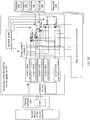
- In order to reduce power consumption, this embodiment of the present invention provides the automatic cable distribution switch apparatus 300. The apparatus further includes at least one analog-to-
digital conversion module 6, and anelectronic switch module 7 that is connected to therelay control module 5 and the at least one analog-to-digital conversion module 6, where each analog-to-digital conversion module 6 is connected to oneterminal 200 by using onerelay 3, as shown inFIG. 3B (this figure uses an example in which the automatic cable distribution switch apparatus 300 is connected to only two access network devices), where - each analog-to-
digital conversion module 6 is configured to convert an analog signal sent by a terminal 200 connected to the analog-to-digital conversion module 6 into a digital signal, and input the digital signal obtained through conversion to theelectronic switch module 7; - the
relay control module 5 is further configured to: after determining that theelectronic switch module 7 receives the digital signal, control theelectronic switch module 7 to determine, in a DSP of an optical network unit, an idle signal input line that is used to transmit a digital signal input by any analog-to-digital conversion module 6; and to input, to the switched access network device by using a corresponding idle signal input line in the DSP of the optical network unit, the digital signal that is input by any analog-to-digital conversion module 6; and - the
electronic switch module 7 is configured to: under the control of therelay control module 5, determine, in the DSP of the optical network unit, the idle signal input line that is used to transmit the digital signal input by the any analog-to-digital conversion module 6; and input, to the switched access network device by using the corresponding idle signal input line in the DSP of the optical network unit, the digital signal that is input by the any analog-to-digital conversion module 6. - In this solution, even though a terminal 200 cannot gain local power, when needing to switch from an access network device currently connected to the terminal 200 to another access network device, the terminal 200 may send an access network device switch instruction to a reverse
power detection module 4. In this case, when receiving the access network device switch instruction, an automatic cable distribution switch apparatus 300 may switch the terminal 200 from the current access network device to another access network device, thereby achieving an effect that automatic cable distribution switch can be performed when the terminal 200 cannot gain local power. - Besides, in this embodiment, routing selection is implemented by using an
electronic switch module 7, that is, theelectronic switch module 7 determines, in a DSP of an optical network unit, an idle signal input line that is used to transmit a digital signal input by any analog-to-digital conversion module 6. A process in which theelectronic switch module 7 performs routing selection consumes less power than a process in which a relay performs routing selection; therefore, power consumption is reduced. - Referring to
FIG. 4 , this embodiment of the present invention further provides an automatic cable cable distribution switch apparatus 300 shown inFIG. 3A orFIG. 3B , where - the terminal 200 is configured to send an access network device switch instruction to the automatic cable distribution switch apparatus 300; and
- the automatic cable distribution switch apparatus 300 is configured to: after receiving the access network device switch instruction sent by the terminal 200, adjust a
relay 3 connected to the terminal 200 sending the access network device switch instruction, so that therelay 3 controls theconnected terminal 200 to switch from any access network device, currently connected to the terminal 200, of at least two access network devices to another access network device of the at least two access network devices. - In this embodiment of the present invention, optionally, the terminal 200 is configured to send an electrical signal to the automatic cable distribution switch apparatus 300; and
- in this case, optionally, the automatic cable distribution switch apparatus 300 is configured to:
- adjust a
relay 3 connected to the terminal 200 sending the electrical signal, so that therelay 3 controls theconnected terminal 200 to switch from any access network device, currently connected to the terminal 200, of the at least two access network devices to another access network device of the at least two access network devices. - In this embodiment of the present invention, optionally, the terminal 200 is configured to deliver a switch signal by using an RNC; and
- in this case, optionally, the automatic cable distribution switch apparatus 300 is configured to:
- adjust a
relay 3 connected to the terminal 200 sending the switch signal, so that therelay 3 controls theconnected terminal 200 to switch from any access network device, currently connected to the terminal 200, of the at least two access network devices to another access network device of the at least two access network devices.
- adjust a
- Further, after the terminal 200 is connected to the access network device, the terminal 200 is further configured to send an analog signal; and
- the automatic cable distribution switch apparatus 300 is further configured to: convert the analog signal sent by the terminal 200 into a digital signal;
- determine, in a DSP of an optical network unit, an idle signal input line that is used to transmit the digital signal; and
- input the digital signal to the switched access network device by using a corresponding idle signal input line in the DSP of the optical network unit.
- In this solution, even though a terminal 200 cannot gain local power, when needing to switch from In this solution, even though a terminal 200 cannot gain local power, when needing to switch from an access network device currently connected to the terminal 200 to another access network device, the terminal 200 may send an access network device switch instruction to a reverse
power detection module 4. In this case, when receiving the access network device switch instruction, an automatic cable distribution switch apparatus 300 may switch the terminal 200 from the current access network device to another access network device, thereby achieving an effect that automatic cable distribution switch can be performed when the terminal 200 cannot gain local power. - Besides, in this system, in this embodiment, the automatic cable distribution switch apparatus 300 implements routing selection by using an
electronic switch module 7, that is, controls theelectronic switch module 7 to determine, in a DSP of an optical network unit, an idle signal input line that is used to transmit a digital signal input by any analog-to-digital conversion module 6. A process in which theelectronic switch module 7 performs routing selection consumes less power than a process in which a relay performs routing selection; therefore, power consumption is reduced. - As shown in
FIG. 5 , this embodiment of the present invention provides an automatic cable distribution switch method, where an automatic cable distribution switch apparatus using the method is connected to at least two access network devices. A process of the method is as follows: Step 500: Receive an access network device switch instruction sent by aterminal 200. - Step 510: Switch the terminal 200 from any access network device, currently connected to the terminal 200, of the at least two access network devices to another access network device of the at least two access network devices according to the access network device switch instruction.
- In this embodiment of the present invention, there are multiple manners of receiving the access network device switch instruction sent by the terminal 200, which, for example, may be receiving an electrical signal sent by the terminal, or may be receiving a switch signal delivered by the terminal 200 by using an RNC. The foregoing descriptions are merely several implementation manners, and there are other manners in an actual application, which are not described in detail herein again.
- Similarly, in this embodiment of the present invention, there also are multiple manners of switching the terminal 200 from any access network device, currently connected to the terminal 200, of the at least two access network devices to another access network device of the at least two access network devices according to the access network device switch instruction. For example:
- the terminal 200 is switched from any access network device, currently connected to the terminal 200, of the at least two access network devices to another
access network terminal 200 is switched from any access network device, currently connected to the terminal 200, of the at least two access network devices to another access network device of the at least two access network devices according to a switch signal. The foregoing descriptions are merely several manners, and there are other manners in an actual application, which are not described in detail herein again. - In an actual application, when the terminal 200 is connected to an access network device, an analog signal sent by the terminal 200 needs to be processed before being input to the access network device by using a DSP of an optical network unit. Therefore, after the switching the terminal 200 from any access network device, currently connected to the terminal 200, of the at least two access network devices to another access network device of the at least two access network devices according to the access network device switch instruction, the method further includes the following operations:
- converting the received analog signal sent by the terminal 200 into a digital signal;
- determining, in a DSP of an optical network unit, an idle signal input line that is used to transmit the digital signal; and
- inputting the digital signal to the switched access network device by using a corresponding idle signal input line in the DSP of the optical network unit.
- In this solution, even though a terminal 200 cannot gain local power, when needing to switch from an access network device currently connected to the terminal 200 to another access network device, the terminal 200 may send an access network device switch instruction to an automatic cable distribution switch apparatus 300. In this case, when receiving the access network device switch instruction, the automatic cable distribution switch apparatus 300 may switch the terminal 200 from the current access network device to another access network device, thereby achieving an effect that automatic cable distribution switch can be performed when the terminal 200 cannot gain local power.
- In conclusion, the embodiments of the present invention provide an automatic cable distribution switch apparatus. The automatic cable distribution switch apparatus is connected to at least two access network devices, and includes at least one relay, a reverse power detection module connected to the at least one relay, and a relay control module that is connected to the reverse power detection module and the at least one relay, where each relay is configured to control a terminal, connected to the relay, to be connected to any access network device of the at least two access network devices within a different time period; the reverse power detection module is configured to receive an access network device switch instruction sent by the terminal; and the relay control module is configured to adjust a
relay 3 connected to the terminal sending the access network device switch configured to adjust arelay 3 connected to the terminal sending the access network device switch instruction, wherein the relay controls the connected terminal to switch from an access network device, currently connected to the terminal, of the at least two access network devices to another access network device of the at least two access network devices. In this solution, when the terminal cannot gain local power, the reverse power detection module can still receive the access network device switch instruction sent by the terminal, thereby implementing interaction between the terminal and the automatic cable distribution switch apparatus. In this case, the relay control module of the automatic cable distribution switch apparatus adjusts therelay 3 connected to the terminal sending the access network device switch instruction, wherein the relay controls the connected terminal to switch from an access network device, currently connected to the terminal, of the at least two access network devices to another access network device of the at least two access network devices, thereby achieving an effect that automatic cable distribution switch can be performed when the terminal cannot gain local power. - Besides, in this system, in this embodiment, the automatic cable distribution switch apparatus 300 further includes an
electronic switch module 7, and implements routing selection by using theelectronic switch module 7, that is, theelectronic switch module 7 is controlled to determine, in a DSP of an optical network unit, an idle signal input line that is used to transmit a digital signal input by any analog-to-digital conversion module 6. A process in which theelectronic switch module 7 performs routing selection consumes less power than a process in which a relay performs routing selection; therefore, power consumption is reduced. - The present invention is described with reference to the flowcharts and/or block diagrams of the method, the device (system), and the computer program product according to the embodiments of the present invention. It should be understood that computer program instructions may be used to implement each process and/or each block in the flowcharts and/or the block diagrams and a combination of a process and/or a block in the flowcharts and/or the block diagrams. These computer program instructions may be provided for a general-purpose computer, a dedicated computer, an embedded processor, or a processor of any other programmable data processing device to generate a machine, so that the instructions executed by a computer or a processor of any other programmable data processing device generate an apparatus for implementing a function in one or more processes in the flowcharts and/or in one or more blocks in the block diagrams.
- These computer program instructions may also be stored in a computer readable memory that can instruct the computer or any other programmable data processing device to work in a specific manner, so that the instructions stored in the computer readable memory generate an artifact that includes an instruction apparatus. The instruction apparatus implements a function in one or more These computer program instructions may also be loaded onto a computer or another programmable data processing device, so that a series of operations and steps are performed on the computer or the another programmable device, thereby generating computer-implemented processing. Therefore, the instructions executed on the computer or the another programmable device provide steps for implementing a function in one or more processes in the flowcharts and/or in one or more blocks in the block diagrams.
- Although the foregoing embodiments of the present invention have been described, persons skilled in the art can make changes and modifications to these embodiments once they learn the basic inventive concept. Therefore, the following claims are intended to be construed as to cover the foregoing embodiments and all changes and modifications falling within the scope of the present invention.
- Obviously, persons skilled in the art can make various modifications and variations to the embodiments of the present invention. The present invention is intended to cover these modifications and variations provided that they fall within the scope of protection defined by the following claims and their equivalent technologies.
Claims (10)
- An automatic cable distribution switch apparatus (300), wherein the automatic cable distribution switch apparatus (300) is connected to at least two access network devices, and comprises at least one relay (3), a reverse power detection module (4) connected to the at least one relay (3), and a relay control module (5) that is connected to the reverse power detection module (4) and the at least one relay (3), wherein
each relay (3) is configured to control a terminal (200), connected to the relay (3), to be connected to any access network device of the at least two access network devices within a different time period;
the reverse power detection module (4) is configured to receive an access network device switch instruction sent by the terminal (200); and
the relay control module (5) is configured to adjust a relay (3) connected to the terminal (200) sending the access network device switch instruction, wherein the relay (3) controls the connected terminal (200) to switch from an access network device, currently connected to the terminal (200), to another access network device of the at least two access network devices;
characterized in that
the apparatus (300) further comprises at least one analog-to-digital conversion module (6) and an electronic switch module (7) connected to both the relay control module (5) and the at least one analog-to-digital conversion module (6), wherein each analog-to-digital conversion module (6) is connected to one terminal (200) by using one relay (3) and wherein each analog-to-digital conversion module (6) is connected to signal input lines of an optical network unit of an access network device by using the electronic switch module (7), wherein
each analog-to-digital conversion module (6) is configured to convert an analog signal sent by a terminal (200) connected to the analog-to-digital conversion module (6) into a digital signal, and input the digital signal obtained through conversion to the electronic switch module (7);
the relay control module (5) is further configured to: after determining that the electronic switch module (7) receives the digital signal, control the electronic switch module (7) to determine, in a digital signal processor DSP of the optical network unit, an idle signal input line that is used to transmit a digital signal input by any analog-to-digital conversion module (6); and to input, to the switched access network device by using a corresponding idle signal input line in the DSP of the optical network unit, the digital signal that is input by any analog-to-digital conversion module (6); and
the electronic switch module (7) is configured to: under the control of the relay control module (5), determine, in the DSP of the optical network unit, the idle signal input line that is used to transmit the digital signal input by the any analog-to-digital conversion module (6); and input, to the switched access network device by using the corresponding idle signal input line in the DSP of the optical network unit, the digital signal that is input by the any analog-to-digital conversion module (6). - The apparatus (300) according to claim 1, wherein the relay (3) is a single-throw double-pole switch.
- The apparatus (300) according to claim 1 or 2, wherein the reverse power detection module (4) is specifically configured to:receive an electrical signal sent by the terminal (200); andthe relay control module (5) is specifically configured to:adjust a relay (3) connected to the terminal (200) sending the electrical signal, wherein the relay (3) controls the connected terminal (200) to switch from an access network device, currently connected to the terminal (200), to another access network device of the at least two access network devices.
- The apparatus (300) according to claim 1 or 2, wherein the reverse power detection module (4) is specifically configured to:receive a switch signal that is delivered by the terminal (200) by using a radio network controller RNC; andthe relay control module (4) is specifically configured to:adjust a relay (3) connected to the terminal (200) sending the switch signal, wherein the relay (3) controls the connected terminal (200) to switch from an access network device, currently connected to the terminal (200), to another access network device of the at least two access network devices.
- An automatic cable distribution switch system, comprising a terminal (200) and an automatic cable distribution switch apparatus (300) connected to at least two access network devices, wherein
the terminal (200) is configured to send an access network device switch instruction to the automatic cable distribution switch apparatus (300); and
the automatic cable distribution switch apparatus (300) is configured to: after receiving the access network device switch instruction sent by the terminal (200), adjust a relay (3) connected to the terminal (200) sending the access network device switch instruction, wherein the relay (3) controls the connected terminal (200) to switch from an access network device, currently connected to the terminal (200), to another access network device of the at least two access network devices;
characterized in that
the terminal (200) is further configured to send an analog signal; and
the automatic cable distribution switch apparatus (300) is further configured to:when switching to signal input lines of an optical network unit of an access network device, to convert the analog signal sent by the terminal (200) into a digital signal;determine, in a digital signal processor DSP of the optical network unit, an idle signal input line that is used to transmit the digital signal; andinput the digital signal to the switched access network device by using a corresponding idle signal input line in the DSP of the optical network unit. - The system according to claim 5, wherein the terminal (200) is specifically configured to:send an electrical signal to the automatic cable distribution switch apparatus (300); andthe automatic cable distribution switch apparatus (300) is specifically configured to:adjust a relay (3) connected to the terminal (200) sending the electrical signal, wherein the relay (3) controls the connected terminal (200) to switch from an access network device, currently connected to the terminal (200), to another access network device of the at least two access network devices.
- The system according to claim 5, wherein the terminal (200) is specifically configured to:deliver a switch signal by using a radio network controller RNC; andthe automatic cable distribution switch apparatus (300) is specifically configured to:adjust a relay (3) connected to the terminal (200) sending the switch signal, wherein the relay (3) controls the connected terminal (200) to switch from an access network device, currently connected to the terminal (200), to another access network device of the at least two access network devices.
- An automatic cable distribution switch method, wherein an automatic cable distribution switch apparatus (300) using the method is connected to at least two access network devices, and the method comprises:receiving (500) an access network device switch instruction sent by a terminal (200); andswitching (510) the terminal (200) from any access network device, currently connected to the terminal (200), to another access network device of the at least two access network devices according to the access network device switch instruction;characterized in that
the method further comprises after switching to signal input lines of an optical network unit of an access network device:converting a received analog signal sent by the terminal (200) into a digital signal;determining, in a digital signal processor DSP of the optical network unit, an idle signal input line that is used to transmit the digital signal; andinputting the digital signal to the switched access network device by using a corresponding idle signal input line in the DSP of the optical network unit. - The method according to claim 8, wherein the receiving (500) an access network device switch instruction sent by a terminal (200) specifically comprises:receiving an electrical signal sent by the terminal (200); andthe switching (510) the terminal (200) from any access network device, currently connected to the terminal (200), to another access network device of the at least two access network devices according to the access network device switch instruction specifically comprises:switching the terminal (200) from any access network device, currently connected to the terminal (200), to another access network device of the at least two access network devices according to the electrical signal.
- The method according to claim 8, wherein the receiving (500) an access network device switch instruction sent by a terminal (200) specifically comprises:receiving a switch signal that is delivered by the terminal (200) by using a radio network controller RNC; andthe switching (510) the terminal (200) from any access network device, currently connected to the terminal (200), to another access network device of the at least two access network devices according to the access network device switch instruction specifically comprises:switching the terminal (200) from any access network device, currently connected to the terminal, to another access network device of the at least two access network devices according to the switch signal.
Applications Claiming Priority (1)
| Application Number | Priority Date | Filing Date | Title |
|---|---|---|---|
| PCT/CN2013/090362 WO2015096044A1 (en) | 2013-12-24 | 2013-12-24 | Automatic wiring switching apparatus and system, and automatic wiring switching method |
Publications (3)
| Publication Number | Publication Date |
|---|---|
| EP2942906A1 EP2942906A1 (en) | 2015-11-11 |
| EP2942906A4 EP2942906A4 (en) | 2016-03-16 |
| EP2942906B1 true EP2942906B1 (en) | 2017-02-22 |
Family
ID=50671634
Family Applications (1)
| Application Number | Title | Priority Date | Filing Date |
|---|---|---|---|
| EP13900051.7A Active EP2942906B1 (en) | 2013-12-24 | 2013-12-24 | Automatic wiring switching apparatus and system, and automatic wiring switching method |
Country Status (4)
| Country | Link |
|---|---|
| US (1) | US9941968B2 (en) |
| EP (1) | EP2942906B1 (en) |
| CN (1) | CN103797814B (en) |
| WO (1) | WO2015096044A1 (en) |
Families Citing this family (5)
| Publication number | Priority date | Publication date | Assignee | Title |
|---|---|---|---|---|
| CN104883632B (en) * | 2015-06-12 | 2018-12-18 | 烽火通信科技股份有限公司 | Realize that VDSL flows the device and method of reverse feeding in PON far end system |
| CN111615019B (en) * | 2019-02-22 | 2022-11-15 | 上海诺基亚贝尔股份有限公司 | Method, apparatus and computer readable storage medium implemented in an optical network |
| CN112003373B (en) * | 2020-08-20 | 2022-08-30 | 广东电网有限责任公司 | Distributed feeder system and power distribution system |
| CN114285010B (en) * | 2021-12-22 | 2024-02-20 | 苏州电力设计研究院有限公司 | Circuit protection adjusting system of self-adaptive grounding mode |
| CN115942406A (en) * | 2022-09-30 | 2023-04-07 | 联想(北京)有限公司 | Electronic equipment and mode switching method |
Family Cites Families (8)
| Publication number | Priority date | Publication date | Assignee | Title |
|---|---|---|---|---|
| GB9624180D0 (en) * | 1996-11-21 | 1997-01-08 | Plessey Telecomm | Telecommunication equipment |
| EP1093255B1 (en) * | 1999-10-14 | 2009-12-16 | Alcatel Lucent | Method for connecting a first user-terminal to a second user-terminal, related devices and related software modules |
| CN1642297A (en) * | 2004-01-18 | 2005-07-20 | 华为技术有限公司 | General distributing frame and intermediate automatic distributing unit |
| CA2595077C (en) * | 2005-01-19 | 2015-08-25 | Telefonaktiebolaget Lm Ericsson (Publ) | A method and apparatus for handling emergency calls |
| EP1988664A1 (en) * | 2007-04-30 | 2008-11-05 | British Telecommunications Public Limited Company | Communications network |
| US20110103348A1 (en) * | 2008-07-07 | 2011-05-05 | Panasonic Corporation | Handover processing method, and mobile terminal and communication management device used in said method |
| CN101790108B (en) * | 2009-01-22 | 2012-12-05 | 汪渝滨 | Automatic wiring device, management system and method |
| CN101854562A (en) * | 2010-05-06 | 2010-10-06 | 华为技术有限公司 | Method for realizing main distributing frame and main distributing frame |
-
2013
- 2013-12-24 EP EP13900051.7A patent/EP2942906B1/en active Active
- 2013-12-24 WO PCT/CN2013/090362 patent/WO2015096044A1/en not_active Ceased
- 2013-12-24 CN CN201380002852.8A patent/CN103797814B/en active Active
-
2016
- 2016-05-05 US US15/147,220 patent/US9941968B2/en active Active
Non-Patent Citations (1)
| Title |
|---|
| None * |
Also Published As
| Publication number | Publication date |
|---|---|
| WO2015096044A1 (en) | 2015-07-02 |
| EP2942906A1 (en) | 2015-11-11 |
| US9941968B2 (en) | 2018-04-10 |
| CN103797814B (en) | 2017-11-17 |
| US20160248512A1 (en) | 2016-08-25 |
| EP2942906A4 (en) | 2016-03-16 |
| CN103797814A (en) | 2014-05-14 |
Similar Documents
| Publication | Publication Date | Title |
|---|---|---|
| EP2942906B1 (en) | Automatic wiring switching apparatus and system, and automatic wiring switching method | |
| EP2201788B1 (en) | Communications network | |
| CN102369737B (en) | Data communication method of optical network system, optical network units and system | |
| EP2897309B1 (en) | Protection switching method, system and apparatus for passive optical network | |
| JP2014011792A (en) | Power supply system in end-user side active multi-service routing of fttx optical network unit | |
| CN104639468A (en) | Optical port adaptive Ethernet switch and adaptive method thereof | |
| WO2020109867A3 (en) | Multi-mode communication device, method and system | |
| KR20140072200A (en) | Apparatus and method for providing protection in a passive optical network | |
| CN102104418A (en) | Transmission control system, subscriber-side communication device, and office-side communication device | |
| CN104954065B (en) | A kind of passive optical network and communication means | |
| WO2016026688A1 (en) | Reverse power feed system | |
| CN115442679A (en) | Method and device for bandwidth adjustment | |
| EP3163794B1 (en) | Power supply method, apparatus, and system | |
| EP3495913B1 (en) | Power supply control for a communication network | |
| WO2015074275A1 (en) | Optical line terminal, distribution point unit, system and data stream scheduling method | |
| CN110166858A (en) | The ONU adaptive method for switching of PON network | |
| CN102082611A (en) | Device and method for distributing light in passive optical network (PON) | |
| CN114609961A (en) | Ultra-remote control system for port loading and unloading equipment | |
| CN111343520A (en) | PON uplink data transmission method, system and device and PON system | |
| CN115412162B (en) | PON optical link protection method and system | |
| CN104579700A (en) | Intelligent optical network terminal and optical network system | |
| EP4160942A1 (en) | Optical line terminal (olt) device and optical path processing method | |
| CN109660022A (en) | A real-time control interaction system and method for master-partner cooperative real-time control | |
| CN106162385B (en) | Method and device for controlling running state of channel terminal | |
| WO2023273943A1 (en) | Onu transmission rate control method, onu, olt, electronic device, and storage medium |
Legal Events
| Date | Code | Title | Description |
|---|---|---|---|
| PUAI | Public reference made under article 153(3) epc to a published international application that has entered the european phase |
Free format text: ORIGINAL CODE: 0009012 |
|
| 17P | Request for examination filed |
Effective date: 20150804 |
|
| AK | Designated contracting states |
Kind code of ref document: A1 Designated state(s): AL AT BE BG CH CY CZ DE DK EE ES FI FR GB GR HR HU IE IS IT LI LT LU LV MC MK MT NL NO PL PT RO RS SE SI SK SM TR |
|
| AX | Request for extension of the european patent |
Extension state: BA ME |
|
| A4 | Supplementary search report drawn up and despatched |
Effective date: 20160215 |
|
| RIC1 | Information provided on ipc code assigned before grant |
Ipc: H04L 12/54 20060101ALI20160209BHEP Ipc: H04L 12/24 20060101AFI20160209BHEP |
|
| GRAP | Despatch of communication of intention to grant a patent |
Free format text: ORIGINAL CODE: EPIDOSNIGR1 |
|
| DAX | Request for extension of the european patent (deleted) | ||
| INTG | Intention to grant announced |
Effective date: 20160915 |
|
| GRAS | Grant fee paid |
Free format text: ORIGINAL CODE: EPIDOSNIGR3 |
|
| GRAA | (expected) grant |
Free format text: ORIGINAL CODE: 0009210 |
|
| AK | Designated contracting states |
Kind code of ref document: B1 Designated state(s): AL AT BE BG CH CY CZ DE DK EE ES FI FR GB GR HR HU IE IS IT LI LT LU LV MC MK MT NL NO PL PT RO RS SE SI SK SM TR |
|
| REG | Reference to a national code |
Ref country code: GB Ref legal event code: FG4D |
|
| REG | Reference to a national code |
Ref country code: CH Ref legal event code: EP |
|
| REG | Reference to a national code |
Ref country code: AT Ref legal event code: REF Ref document number: 870037 Country of ref document: AT Kind code of ref document: T Effective date: 20170315 |
|
| REG | Reference to a national code |
Ref country code: IE Ref legal event code: FG4D |
|
| REG | Reference to a national code |
Ref country code: DE Ref legal event code: R096 Ref document number: 602013017834 Country of ref document: DE |
|
| REG | Reference to a national code |
Ref country code: LT Ref legal event code: MG4D |
|
| REG | Reference to a national code |
Ref country code: NL Ref legal event code: MP Effective date: 20170222 |
|
| REG | Reference to a national code |
Ref country code: AT Ref legal event code: MK05 Ref document number: 870037 Country of ref document: AT Kind code of ref document: T Effective date: 20170222 |
|
| PG25 | Lapsed in a contracting state [announced via postgrant information from national office to epo] |
Ref country code: FI Free format text: LAPSE BECAUSE OF FAILURE TO SUBMIT A TRANSLATION OF THE DESCRIPTION OR TO PAY THE FEE WITHIN THE PRESCRIBED TIME-LIMIT Effective date: 20170222 Ref country code: GR Free format text: LAPSE BECAUSE OF FAILURE TO SUBMIT A TRANSLATION OF THE DESCRIPTION OR TO PAY THE FEE WITHIN THE PRESCRIBED TIME-LIMIT Effective date: 20170523 Ref country code: HR Free format text: LAPSE BECAUSE OF FAILURE TO SUBMIT A TRANSLATION OF THE DESCRIPTION OR TO PAY THE FEE WITHIN THE PRESCRIBED TIME-LIMIT Effective date: 20170222 Ref country code: NO Free format text: LAPSE BECAUSE OF FAILURE TO SUBMIT A TRANSLATION OF THE DESCRIPTION OR TO PAY THE FEE WITHIN THE PRESCRIBED TIME-LIMIT Effective date: 20170522 Ref country code: LT Free format text: LAPSE BECAUSE OF FAILURE TO SUBMIT A TRANSLATION OF THE DESCRIPTION OR TO PAY THE FEE WITHIN THE PRESCRIBED TIME-LIMIT Effective date: 20170222 |
|
| PG25 | Lapsed in a contracting state [announced via postgrant information from national office to epo] |
Ref country code: LV Free format text: LAPSE BECAUSE OF FAILURE TO SUBMIT A TRANSLATION OF THE DESCRIPTION OR TO PAY THE FEE WITHIN THE PRESCRIBED TIME-LIMIT Effective date: 20170222 Ref country code: SE Free format text: LAPSE BECAUSE OF FAILURE TO SUBMIT A TRANSLATION OF THE DESCRIPTION OR TO PAY THE FEE WITHIN THE PRESCRIBED TIME-LIMIT Effective date: 20170222 Ref country code: PT Free format text: LAPSE BECAUSE OF FAILURE TO SUBMIT A TRANSLATION OF THE DESCRIPTION OR TO PAY THE FEE WITHIN THE PRESCRIBED TIME-LIMIT Effective date: 20170622 Ref country code: ES Free format text: LAPSE BECAUSE OF FAILURE TO SUBMIT A TRANSLATION OF THE DESCRIPTION OR TO PAY THE FEE WITHIN THE PRESCRIBED TIME-LIMIT Effective date: 20170222 Ref country code: AT Free format text: LAPSE BECAUSE OF FAILURE TO SUBMIT A TRANSLATION OF THE DESCRIPTION OR TO PAY THE FEE WITHIN THE PRESCRIBED TIME-LIMIT Effective date: 20170222 Ref country code: RS Free format text: LAPSE BECAUSE OF FAILURE TO SUBMIT A TRANSLATION OF THE DESCRIPTION OR TO PAY THE FEE WITHIN THE PRESCRIBED TIME-LIMIT Effective date: 20170222 Ref country code: BG Free format text: LAPSE BECAUSE OF FAILURE TO SUBMIT A TRANSLATION OF THE DESCRIPTION OR TO PAY THE FEE WITHIN THE PRESCRIBED TIME-LIMIT Effective date: 20170522 Ref country code: NL Free format text: LAPSE BECAUSE OF NON-PAYMENT OF DUE FEES Effective date: 20170222 |
|
| PG25 | Lapsed in a contracting state [announced via postgrant information from national office to epo] |
Ref country code: RO Free format text: LAPSE BECAUSE OF FAILURE TO SUBMIT A TRANSLATION OF THE DESCRIPTION OR TO PAY THE FEE WITHIN THE PRESCRIBED TIME-LIMIT Effective date: 20170222 Ref country code: CZ Free format text: LAPSE BECAUSE OF FAILURE TO SUBMIT A TRANSLATION OF THE DESCRIPTION OR TO PAY THE FEE WITHIN THE PRESCRIBED TIME-LIMIT Effective date: 20170222 Ref country code: SK Free format text: LAPSE BECAUSE OF FAILURE TO SUBMIT A TRANSLATION OF THE DESCRIPTION OR TO PAY THE FEE WITHIN THE PRESCRIBED TIME-LIMIT Effective date: 20170222 Ref country code: EE Free format text: LAPSE BECAUSE OF FAILURE TO SUBMIT A TRANSLATION OF THE DESCRIPTION OR TO PAY THE FEE WITHIN THE PRESCRIBED TIME-LIMIT Effective date: 20170222 |
|
| REG | Reference to a national code |
Ref country code: FR Ref legal event code: PLFP Year of fee payment: 5 |
|
| REG | Reference to a national code |
Ref country code: DE Ref legal event code: R097 Ref document number: 602013017834 Country of ref document: DE |
|
| PG25 | Lapsed in a contracting state [announced via postgrant information from national office to epo] |
Ref country code: PL Free format text: LAPSE BECAUSE OF FAILURE TO SUBMIT A TRANSLATION OF THE DESCRIPTION OR TO PAY THE FEE WITHIN THE PRESCRIBED TIME-LIMIT Effective date: 20170222 Ref country code: DK Free format text: LAPSE BECAUSE OF FAILURE TO SUBMIT A TRANSLATION OF THE DESCRIPTION OR TO PAY THE FEE WITHIN THE PRESCRIBED TIME-LIMIT Effective date: 20170222 Ref country code: SM Free format text: LAPSE BECAUSE OF FAILURE TO SUBMIT A TRANSLATION OF THE DESCRIPTION OR TO PAY THE FEE WITHIN THE PRESCRIBED TIME-LIMIT Effective date: 20170222 |
|
| PLBE | No opposition filed within time limit |
Free format text: ORIGINAL CODE: 0009261 |
|
| STAA | Information on the status of an ep patent application or granted ep patent |
Free format text: STATUS: NO OPPOSITION FILED WITHIN TIME LIMIT |
|
| 26N | No opposition filed |
Effective date: 20171123 |
|
| PG25 | Lapsed in a contracting state [announced via postgrant information from national office to epo] |
Ref country code: SI Free format text: LAPSE BECAUSE OF FAILURE TO SUBMIT A TRANSLATION OF THE DESCRIPTION OR TO PAY THE FEE WITHIN THE PRESCRIBED TIME-LIMIT Effective date: 20170222 |
|
| REG | Reference to a national code |
Ref country code: DE Ref legal event code: R119 Ref document number: 602013017834 Country of ref document: DE |
|
| REG | Reference to a national code |
Ref country code: IE Ref legal event code: MM4A |
|
| PG25 | Lapsed in a contracting state [announced via postgrant information from national office to epo] |
Ref country code: MT Free format text: LAPSE BECAUSE OF NON-PAYMENT OF DUE FEES Effective date: 20171224 Ref country code: LU Free format text: LAPSE BECAUSE OF NON-PAYMENT OF DUE FEES Effective date: 20171224 |
|
| REG | Reference to a national code |
Ref country code: BE Ref legal event code: MM Effective date: 20171231 |
|
| PG25 | Lapsed in a contracting state [announced via postgrant information from national office to epo] |
Ref country code: DE Free format text: LAPSE BECAUSE OF NON-PAYMENT OF DUE FEES Effective date: 20180703 Ref country code: IE Free format text: LAPSE BECAUSE OF NON-PAYMENT OF DUE FEES Effective date: 20171224 |
|
| PG25 | Lapsed in a contracting state [announced via postgrant information from national office to epo] |
Ref country code: BE Free format text: LAPSE BECAUSE OF NON-PAYMENT OF DUE FEES Effective date: 20171231 |
|
| PG25 | Lapsed in a contracting state [announced via postgrant information from national office to epo] |
Ref country code: HU Free format text: LAPSE BECAUSE OF FAILURE TO SUBMIT A TRANSLATION OF THE DESCRIPTION OR TO PAY THE FEE WITHIN THE PRESCRIBED TIME-LIMIT; INVALID AB INITIO Effective date: 20131224 Ref country code: MC Free format text: LAPSE BECAUSE OF FAILURE TO SUBMIT A TRANSLATION OF THE DESCRIPTION OR TO PAY THE FEE WITHIN THE PRESCRIBED TIME-LIMIT Effective date: 20170222 |
|
| PG25 | Lapsed in a contracting state [announced via postgrant information from national office to epo] |
Ref country code: CY Free format text: LAPSE BECAUSE OF FAILURE TO SUBMIT A TRANSLATION OF THE DESCRIPTION OR TO PAY THE FEE WITHIN THE PRESCRIBED TIME-LIMIT Effective date: 20170222 |
|
| PG25 | Lapsed in a contracting state [announced via postgrant information from national office to epo] |
Ref country code: MK Free format text: LAPSE BECAUSE OF FAILURE TO SUBMIT A TRANSLATION OF THE DESCRIPTION OR TO PAY THE FEE WITHIN THE PRESCRIBED TIME-LIMIT Effective date: 20170222 |
|
| PG25 | Lapsed in a contracting state [announced via postgrant information from national office to epo] |
Ref country code: TR Free format text: LAPSE BECAUSE OF FAILURE TO SUBMIT A TRANSLATION OF THE DESCRIPTION OR TO PAY THE FEE WITHIN THE PRESCRIBED TIME-LIMIT Effective date: 20170222 |
|
| PG25 | Lapsed in a contracting state [announced via postgrant information from national office to epo] |
Ref country code: AL Free format text: LAPSE BECAUSE OF FAILURE TO SUBMIT A TRANSLATION OF THE DESCRIPTION OR TO PAY THE FEE WITHIN THE PRESCRIBED TIME-LIMIT Effective date: 20170222 Ref country code: IS Free format text: LAPSE BECAUSE OF FAILURE TO SUBMIT A TRANSLATION OF THE DESCRIPTION OR TO PAY THE FEE WITHIN THE PRESCRIBED TIME-LIMIT Effective date: 20170622 |
|
| PGFP | Annual fee paid to national office [announced via postgrant information from national office to epo] |
Ref country code: IT Payment date: 20241112 Year of fee payment: 12 |
|
| PGFP | Annual fee paid to national office [announced via postgrant information from national office to epo] |
Ref country code: CH Payment date: 20250101 Year of fee payment: 12 |
|
| PGFP | Annual fee paid to national office [announced via postgrant information from national office to epo] |
Ref country code: GB Payment date: 20251030 Year of fee payment: 13 |
|
| PGFP | Annual fee paid to national office [announced via postgrant information from national office to epo] |
Ref country code: FR Payment date: 20251110 Year of fee payment: 13 |