EP2942867A2 - Induction motor speed estimation - Google Patents
Induction motor speed estimation Download PDFInfo
- Publication number
- EP2942867A2 EP2942867A2 EP15164509.0A EP15164509A EP2942867A2 EP 2942867 A2 EP2942867 A2 EP 2942867A2 EP 15164509 A EP15164509 A EP 15164509A EP 2942867 A2 EP2942867 A2 EP 2942867A2
- Authority
- EP
- European Patent Office
- Prior art keywords
- induction motor
- current
- frequency
- slip
- fft
- Prior art date
- Legal status (The legal status is an assumption and is not a legal conclusion. Google has not performed a legal analysis and makes no representation as to the accuracy of the status listed.)
- Granted
Links
- 230000006698 induction Effects 0.000 title claims abstract description 110
- 238000000034 method Methods 0.000 claims abstract description 21
- 238000004364 calculation method Methods 0.000 claims description 29
- 238000005259 measurement Methods 0.000 claims description 7
- 238000012544 monitoring process Methods 0.000 description 5
- 238000001228 spectrum Methods 0.000 description 5
- 238000001514 detection method Methods 0.000 description 3
- 230000036541 health Effects 0.000 description 3
- 238000012423 maintenance Methods 0.000 description 3
- 230000008439 repair process Effects 0.000 description 3
- 230000001360 synchronised effect Effects 0.000 description 3
- 230000008878 coupling Effects 0.000 description 2
- 238000010168 coupling process Methods 0.000 description 2
- 238000005859 coupling reaction Methods 0.000 description 2
- MGIUUAHJVPPFEV-ABXDCCGRSA-N magainin ii Chemical compound C([C@H](NC(=O)[C@H](CCCCN)NC(=O)CNC(=O)[C@@H](NC(=O)CN)[C@@H](C)CC)C(=O)N[C@@H](CC(C)C)C(=O)N[C@@H](CC=1NC=NC=1)C(=O)N[C@@H](CO)C(=O)N[C@@H](C)C(=O)N[C@@H](CCCCN)C(=O)N[C@@H](CCCCN)C(=O)N[C@@H](CC=1C=CC=CC=1)C(=O)NCC(=O)N[C@@H](CCCCN)C(=O)N[C@@H](C)C(=O)N[C@@H](CC=1C=CC=CC=1)C(=O)N[C@@H](C(C)C)C(=O)NCC(=O)N[C@@H](CCC(O)=O)C(=O)N[C@@H]([C@@H](C)CC)C(=O)N[C@@H](CCSC)C(=O)N[C@@H](CC(N)=O)C(=O)N[C@@H](CO)C(O)=O)C1=CC=CC=C1 MGIUUAHJVPPFEV-ABXDCCGRSA-N 0.000 description 2
- 238000012986 modification Methods 0.000 description 2
- 230000004048 modification Effects 0.000 description 2
- 230000002159 abnormal effect Effects 0.000 description 1
- 238000003491 array Methods 0.000 description 1
- 230000002950 deficient Effects 0.000 description 1
- 230000001419 dependent effect Effects 0.000 description 1
- 230000003993 interaction Effects 0.000 description 1
- 238000004519 manufacturing process Methods 0.000 description 1
- 230000003287 optical effect Effects 0.000 description 1
- 239000010979 ruby Substances 0.000 description 1
- 229910001750 ruby Inorganic materials 0.000 description 1
- 230000001131 transforming effect Effects 0.000 description 1
Images


Classifications
-
- H—ELECTRICITY
- H02—GENERATION; CONVERSION OR DISTRIBUTION OF ELECTRIC POWER
- H02P—CONTROL OR REGULATION OF ELECTRIC MOTORS, ELECTRIC GENERATORS OR DYNAMO-ELECTRIC CONVERTERS; CONTROLLING TRANSFORMERS, REACTORS OR CHOKE COILS
- H02P23/00—Arrangements or methods for the control of AC motors characterised by a control method other than vector control
- H02P23/08—Controlling based on slip frequency, e.g. adding slip frequency and speed proportional frequency
-
- H—ELECTRICITY
- H02—GENERATION; CONVERSION OR DISTRIBUTION OF ELECTRIC POWER
- H02P—CONTROL OR REGULATION OF ELECTRIC MOTORS, ELECTRIC GENERATORS OR DYNAMO-ELECTRIC CONVERTERS; CONTROLLING TRANSFORMERS, REACTORS OR CHOKE COILS
- H02P23/00—Arrangements or methods for the control of AC motors characterised by a control method other than vector control
- H02P23/14—Estimation or adaptation of motor parameters, e.g. rotor time constant, flux, speed, current or voltage
-
- H—ELECTRICITY
- H02—GENERATION; CONVERSION OR DISTRIBUTION OF ELECTRIC POWER
- H02P—CONTROL OR REGULATION OF ELECTRIC MOTORS, ELECTRIC GENERATORS OR DYNAMO-ELECTRIC CONVERTERS; CONTROLLING TRANSFORMERS, REACTORS OR CHOKE COILS
- H02P29/00—Arrangements for regulating or controlling electric motors, appropriate for both AC and DC motors
- H02P29/02—Providing protection against overload without automatic interruption of supply
- H02P29/024—Detecting a fault condition, e.g. short circuit, locked rotor, open circuit or loss of load
- H02P29/0241—Detecting a fault condition, e.g. short circuit, locked rotor, open circuit or loss of load the fault being an overvoltage
-
- H—ELECTRICITY
- H02—GENERATION; CONVERSION OR DISTRIBUTION OF ELECTRIC POWER
- H02P—CONTROL OR REGULATION OF ELECTRIC MOTORS, ELECTRIC GENERATORS OR DYNAMO-ELECTRIC CONVERTERS; CONTROLLING TRANSFORMERS, REACTORS OR CHOKE COILS
- H02P21/00—Arrangements or methods for the control of electric machines by vector control, e.g. by control of field orientation
- H02P21/14—Estimation or adaptation of machine parameters, e.g. flux, current or voltage
- H02P21/18—Estimation of position or speed
-
- H—ELECTRICITY
- H02—GENERATION; CONVERSION OR DISTRIBUTION OF ELECTRIC POWER
- H02P—CONTROL OR REGULATION OF ELECTRIC MOTORS, ELECTRIC GENERATORS OR DYNAMO-ELECTRIC CONVERTERS; CONTROLLING TRANSFORMERS, REACTORS OR CHOKE COILS
- H02P23/00—Arrangements or methods for the control of AC motors characterised by a control method other than vector control
- H02P23/16—Controlling the angular speed of one shaft
-
- H—ELECTRICITY
- H02—GENERATION; CONVERSION OR DISTRIBUTION OF ELECTRIC POWER
- H02P—CONTROL OR REGULATION OF ELECTRIC MOTORS, ELECTRIC GENERATORS OR DYNAMO-ELECTRIC CONVERTERS; CONTROLLING TRANSFORMERS, REACTORS OR CHOKE COILS
- H02P27/00—Arrangements or methods for the control of AC motors characterised by the kind of supply voltage
- H02P27/02—Arrangements or methods for the control of AC motors characterised by the kind of supply voltage using supply voltage with constant frequency and variable amplitude
- H02P27/026—Arrangements or methods for the control of AC motors characterised by the kind of supply voltage using supply voltage with constant frequency and variable amplitude whereby the speed is regulated by measuring the motor speed and comparing it with a given physical value
Definitions
- Determining the current FFT can include transforming a time domain current signal into a frequency domain current signal.
- Determining the current FFT can include utilizing a Prime-factor FFT algorithm, a Brunn's FFT algorithm or a Cooley-Tukey FFT algorithm.
- I k and V k are motor current and motor voltage at k th frequency respectively.
- Equations (3) and (4) can further provide magnitude and phase of k th harmonic and thus, magnitude and phase spectrums can be obtained.
- a magnitude of the motor current for k th harmonic can be given as A k 2 + B k 2 and a phase of the motor current for the k th harmonic can be given as tan -1 ( B k / A k ).
- motor slip calculation module 44 determines a motor slip of the motor for a given condition based on the motor current FFT as given by equation (3) or the respective magnitude spectrum discussed above. In an alternative embodiment, motor slip calculation module 44 determines the motor slip based on electric power P consumed by the motor for the given condition. The electric power P may further be calculated based on the motor current FFT and the motor voltage FFT given by equations (3) and (4) above. Details of both embodiments of slip calculation module 44 mentioned above will be discussed with respect to figures 2 and 3 respectively.
- step 66 includes determining the actual misalignment frequency f mis based on a first magnitude mag 1 of the first current harmonic, a second magnitude mag 2 of a second current harmonic having the first frequency and the values of the first frequency f mis-approx and the second frequency f 2 .
Landscapes
- Engineering & Computer Science (AREA)
- Power Engineering (AREA)
- Control Of Ac Motors In General (AREA)
Abstract
Description
- Embodiments of invention relate to inductor motors and more specifically to speed estimation of inductor motors.
- Industrial motors are critical components of industrial applications. Failure of industrial motors not only leads to repair of the motors themselves, but also causes production loss, which usually is more costly than the motor itself. The cost associated with the repair or maintenance of motors can be minimized by closely monitoring the motor's health condition and schedule maintenance in a proactive manner. Therefore, monitoring the health condition of motors during operation is highly desired by the customer to minimize outage and the associate cost with motor maintenance and repair.
- Induction motors are one of the most commonly used motors in industrial applications. The most typical failure mode of large induction motors include stator inter-turn fault, broken rotor bar, defective bearing, rotor eccentricity, shaft misalignment, foundation looseness etc. Reliable detection of these failures at incipient stage is critical for the condition monitoring of these motors. In addition to the motor anomaly detection, performance estimation, including the motor's output torque, efficiency, energy usage, etc., is another critical set of parameters to monitor for induction motors. Any trending of these performance related parameters may indicate abnormal condition of the motor's operation.
- A rotor speed measurement of induction motor is required by many monitoring and diagnostics modules, such as torque estimation, efficiency estimation, broken rotor bar detection, etc. Furthermore, for closed loop control of induction motors, speed determination is necessary.
- Therefore, there exists a need for a system and a method for determining speed of induction motors.
- In accordance with an embodiment of the present technique, a method for estimating a speed of an induction motor is provided. The method includes applying a voltage to the induction motor, measuring a current of the induction motor and determining a current fast fourier transform (FFT) of the current. The method further includes determining a slip of the induction motor based on the current FFT and estimating the speed of the induction motor based on the slip of the induction motor.
- Determining the current FFT can include transforming a time domain current signal into a frequency domain current signal.
- Determining the current FFT can include utilizing a Prime-factor FFT algorithm, a Brunn's FFT algorithm or a Cooley-Tukey FFT algorithm.
- The current FFT can include a plurality of magnitudes and phases of current harmonics.
- The slip of the induction motor can be determined based on a misalignment frequency calculated from the current harmonic, a rated frequency and a number of poles. Determining the slip of the induction motor can further comprise determining a first frequency of the induction motor based on a relationship between the rated frequency and the number of poles of the induction motor. The method can further comprise determining a first current harmonic from a motor current FFT, wherein the first current harmonic has a second frequency which is adjacent to the first frequency and has a higher magnitude compared to other current harmonics which have frequencies adjacent to the first frequency. The method can comprise determining the misalignment frequency of the induction motor based on a relationship between a first magnitude of the first current harmonic, a second magnitude of a second current harmonic having the first frequency, the first frequency and the second frequency.
- The method can further comprise determining a voltage fast fourier transform (FFT) of the voltage. Determining the slip of the induction motor can comprise determining a relationship between a rated power and a rated slip of the induction motor and an input power of the induction motor. The input power of the induction motor can be determined based on the voltage FFT and the current FFT.
- In accordance with another embodiment of the present technique, a system including a power supply to provide a voltage to an induction motor and a measurement unit to measure a current of the induction motor is provided. The system also includes a processor to estimate a speed of the induction motor. The processor includes a fast fourier transform (FFT) module to determine a current FFT of the current, a slip calculation module to determine a slip of the induction motor based on the current FFT and a speed calculation module to estimate a speed of the induction motor based on the slip of the induction motor.
- The power supply can comprise a direct current (DC) to alternating current (AC) converter.
- The slip calculation module can determine the slip of the induction motor based on a misalignment frequency calculated from the current harmonic, a rated frequency and a number of poles. The slip calculation module can be configured to determine a first frequency of the induction motor based on a relationship between the rated frequency and the number of poles of the induction motor. The processor can be further configured to determine a first current harmonic from a motor current FFT, wherein the first current harmonic has a second frequency which is adjacent to the first frequency and has a higher magnitude compared to other current harmonics which have frequencies adjacent to the first frequency. The processor can be further configured to determine the misalignment frequency of the induction motor based on a relationship between a first magnitude of the first current harmonic, a second magnitude of a second current harmonic having the first frequency, the first frequency and the second frequency.
- The FFT module can be further configured to determine a voltage fast fourier transform (FFT) of the voltage. The slip calculation module can be further configured to determine the slip based on a relationship between a rated power and a rated slip of the induction motor and an input power of the induction motor. The processor can be further configured to determine the input power of the induction motor based on the voltage FFT and the current FFT.
- These and other features, aspects, and advantages of the present invention will become better understood when the following detailed description is read with reference to the accompanying drawings in which like characters represent like parts throughout the drawings, wherein:
-
FIG. 1 is a diagrammatical representation of a system for an induction motor control; -
FIG. 2 is a diagrammatical representation of an exemplary embodiment of a speed estimation module for use in the system ofFIG. 1 , according to aspects of the present disclosure; -
FIG. 3 is a diagrammatical representation of an exemplary embodiment of a motor slip calculation method used inFIG. 2 , according to aspects of the present disclosure; -
FIG. 4 is a diagrammatical representation of another embodiment of a motor slip calculation method used inFIG. 2 , according to aspects of the present disclosure; and -
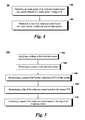
FIG. 5 is a flow chart representation of a method of estimating speed of an induction motor, according to aspects of the present disclosure. - Unless defined otherwise, technical and scientific terms used herein have the same meaning as is commonly understood by one of ordinary skill in the art to which this disclosure belongs. The terms "first", "second", and the like, as used herein do not denote any order, quantity, or importance, but rather are used to distinguish one element from another. Also, the terms "a" and "an" do not denote a limitation of quantity, but rather denote the presence of at least one of the referenced items. The term "or" is meant to be inclusive and mean one, some, or all of the listed items. The use of "including," "comprising" or "having" and variations thereof herein are meant to encompass the items listed thereafter and equivalents thereof as well as additional items. The terms "connected" and "coupled" are not restricted to physical or mechanical connections or couplings, and can include electrical connections or couplings, whether direct or indirect. Furthermore, the terms "circuit" and "circuitry" and "controller" may include either a single component or a plurality of components, which are either active and/or passive and are connected or otherwise coupled together to provide the described function.
- Turning now to the drawings, by way of example in
FIG. 1 , asystem 10 for induction motor speed estimation is depicted. In one embodiment, thesystem 10 for induction motor speed estimation may include apower supply 12, aninduction motor 14, ameasurement unit 17, aload 15 and aprocessor 16. In one embodiment, thepower supply 12 may include an alternating current source such as a generator or a power grid. In another embodiment, thepower supply 12 may include a power converter such as a direct current (DC) to alternating current (AC) converter. In addition, theinduction motor 14 may be a three phase motor and sopower supply 12 may also be a three phase power supply. Also, theload 15 may include a mechanical load such as an overhead crane, a compressor, an industrial drive, an electric vehicle, and the like.. - In general,
induction motor 14 includes a stator (not shown) and a rotor (not shown). Thepower supply 12 applies a voltage across the stator and theload 15 is connected to the rotor via a mechanical shaft. When the voltage is applied across the stator of theinduction motor 14, it produces a rotating magnetic field which induces currents in the rotor of the induction motor. The rotor in turn produces another magnetic field and the interaction between the rotating magnetic field and the rotor magnetic field causes the rotor to rotate and in turn theload 15 rotates.Measurement unit 17 measures a current and the voltage of the induction motor and provides it toprocessor 16. It should be noted thatsystem 10 may further include analog to digital converters, digital to analog converters, filters and other elements which may be needed for overall operation but are not shown inFig. 1 . -
Processor 16 includes aspeed estimation module 18 which estimates a speed of the induction motor based on various measurements. In one embodiment,processor 16 may also control various motor parameters of the induction motor including speed, torque etc.Processor 16 may provide control signals topower supply 12 which in turn controls applied voltage/frequency across the induction motor to control the motor parameters. -
Processor 16 may include a computer, a digital signal processor (DSP) or a Field Programmable Gate Arrays (FPGA). Also, the functions of theprocessor 16 may be implemented in a variety of programming languages, including but not limited to Ruby, Hypertext Pre-processor (PHP), Perl, Delphi, Python, C, C++, or Java. Such code may be stored or adapted for storage on one or more tangible, machine-readable media, such as on data repository chips, local or remote hard disks, optical disks (that is, CDs or DVDs), solid-state drives, or other media, which may be accessed by the processor-based system to execute the stored code. Further, in certain embodiments, thesystem 10 may include a display unit (not shown). In some embodiments, the display unit may form part of theprocessor 16 or thespeed estimation module 18. - Referring now to
FIG. 2 , a diagrammatical representation of an exemplary embodiment of aspeed estimation module 40 for use in the system ofFIG. 1 according to aspects of the present disclosure is depicted. In one embodiment,speed estimation module 40 includes a Fast Fourier Transform (FFT)module 42, a motorslip calculation module 44, a motorspeed calculation module 46 and adisplay unit 48. -
FFT module 42 may receive inputs such as a motor voltage vm and a motor current im. It should be noted that motor voltage vm and motor current im may be three phase quantities.FFT module 42 transforms time domain motor voltage vm and motor current im signals into frequency domain signals. In otherwords FFT module 42 generates a frequency spectrum of motor voltage vm and motor current im. Generating the frequency spectrum includes determining magnitudes and phases of various component frequencies (i.e., harmonics) of signals vm and im. Various FFT algorithms may be utilized byFFT module 42 to generate the frequency spectrum. Examples of FFT algorithms include Prime-factor FFT algorithm, Brunn's FFT algorithm, Cooley-Tukey FFT algorithm etc. In one embodiment, a formula used to transform time domain motor current im and motor voltage vm into frequency domain may be given as :

where k is a harmonic number varying from 0 to N-1, n is a sample number varying from 0 to N-1, and Ik and Vk are motor current and motor voltage at k th frequency respectively. As can be seen from above equations both Ik and Vk have a real component and an imaginary components and can further be represented as:

where A and B are real and imaginary components of the motor current and C and D are real and imaginary components of the motor voltage respectively. Equations (3) and (4) can further provide magnitude and phase of k th harmonic and thus, magnitude and phase spectrums can be obtained. For example, a magnitude of the motor current for k th harmonic can be given as
- Referring back to
Fig. 2 , in an embodiment, motorslip calculation module 44 determines a motor slip of the motor for a given condition based on the motor current FFT as given by equation (3) or the respective magnitude spectrum discussed above. In an alternative embodiment, motorslip calculation module 44 determines the motor slip based on electric power P consumed by the motor for the given condition. The electric power P may further be calculated based on the motor current FFT and the motor voltage FFT given by equations (3) and (4) above. Details of both embodiments ofslip calculation module 44 mentioned above will be discussed with respect tofigures 2 and3 respectively. - Once the motor slip is calculated by motor
slip calculation module 44, the motorspeed calculation module 46 estimates the speed of the induction motor based on the motor slip and may display it on thedisplay unit 48. In one embodiment, motorspeed calculation module 46 estimates the speed of the induction motor based on the following equation:
where ωr is the speed of the induction motor in revolutions/minute, ωs is a synchronous speed of the induction motor in revolutions/minute and s is the motor slip. The synchronous speed of the induction motor may be calculated by following equation:
where f is a rated frequency of the induction motor and p is a number of poles of the induction motor. - Referring now to
FIG. 3 ,diagrammatical representation 60 of an exemplary embodiment of a slip calculation method used inmotor calculation module 44 ofFIG. 2 is depicted. Theslip calculation method 60 includes determining a first frequency instep 62. The first frequency may also be referred to as an approximate mis-alignment frequency fmis-approx and is determined based on a relationship between the number of poles p and the rated frequency f of the induction motor. In one embodiment, an actual mis-alignment frequency fmis may be given by equation:
where s is the motor slip, k is an harmonic dependent integer. In one embodiment, k is equal to 1. It should be noted that the mis-alignment frequency is a harmonic signal which is a result of the shaft misalignment of the induction motor and which can be used to evaluate the speed of the induction motor. Since motor slip s which is generally very small is not known at this step, it is approximated or substituted to be zero i.e., s=0. Thus, the approximate misalignment frequency fmis-approx is then given as
-
Slip calculation method 60 further includes determining a first current harmonic instep 64. The first current harmonic is determined from the motor current FFT and has a second frequency f2 which is adjacent to the first frequency fmis-approx. The first motor current harmonic also has a higher magnitude compared to other current harmonics having frequencies adjacent to the first frequency. For example, assume the first frequency is 48 Hz and there are two current harmonics with frequencies 47.9 Hz and 48.1 Hz which are adjacent to the first frequency. If the two current harmonics (47.1 Hz and 48.1 Hz) have magnitudes 0.9 per unit (pu) and 0.94 pu respectively, then the second frequency selected would be the frequency 48.1 Hz. This is so because the current harmonic of frequency 48.1 Hz has relatively higher magnitude compared to other current harmonics having adjacent frequencies to the first frequency. - Once the first current harmonic is determined,
step 66 includes determining the actual misalignment frequency fmis based on a first magnitude mag1 of the first current harmonic, a second magnitude mag2 of a second current harmonic having the first frequency and the values of the first frequency fmis-approx and the second frequency f2. In one embodiment, the misalignment frequency fmis may be given as
where b=(2a-1)/(a+1) and a=mag2 /mag1 . -
Slip calculation method 60 further includes determining the motor slip based on the misalignment frequency fmis instep 68. The motor slip s may be calculated as
where again f is the rated frequency of the induction motor, p is the number of poles of the induction motor and k is an integer. This motor slip may then be utilized to determine the motor speed as per equation (5). - Referring now to
FIG. 4 ,diagrammatical representation 80 of another exemplary embodiment of a slip calculation method used inmotor calculation module 44 ofFIG. 2 is depicted. Theslip calculation method 80 includes determining an input power Pinput of the induction motor instep 82. The input power of the induction motor is determined based on a relationship between the motor current FFT and the motor voltage FFT. In one embodiment, the input power Pinput may be given by equation:
where Ak, Ck are real components of the phase current Ik and phase voltage Vk respectively and Bk, Dk are imaginary components of the phase current Ik and phase voltage Vk respectively. Furthermore, k is the harmonic number varying from 0 to N/2-1 where N is the number of samples of time domain phase current Ik and/or phase voltage Vk. In another embodiment, where the induction motor may be unbalanced, the input power Pinput may be determined by determining input power for each phase separately and then adding them together. - The
slip calculation method 80 further includes determining the motor slip s instep 84. In this embodiment, the motor slip s is determined based on a relationship between a rated power Prated, a rated slip srated and the input power Pinput of the induction motor, i.e.,

where ωr_rated is the rated speed of the induction motor and and ωs is the synchronous speed of the induction motor determined as per equation (6). Both rated power Prated and rated speed ωr_rated may be determined from the induction motor name plate. This motor slip may then be utilized to determine the motor speed as per equation (5). - Referring now to
FIG. 5 , aflow chart representation 100 of a method for estimating a speed of an induction motor is depicted. Instep 102, themethod 100 includes applying a motor voltage to the induction motor. The motor voltage may be a three phase voltage and may be applied via a DC to AC converter. Instep 104, a motor current of the induction motor is measured and instep 106, a current fast fourier transform of the motor current is determined. Various FFT algorithms may be utilized determine the motor current FFT. Examples of FFT algorithms include Prime-factor FFT algorithm, Brunn's FFT algorithm, Cooley-Tukey FFT algorithm etc. Instep 108, a motor slip of the induction motor is determined based on the motor current FFT and finally instep 110, the speed of the induction motor is estimated based on the motor slip. - Advantages of the present technique include sensorless speed measurement which enables online motor health monitoring. Furthermore, the technique is a low cost solution and has high accuracy and low dependence on data quality.
- While only certain features of the invention have been illustrated and described herein, many modifications and changes will occur to those skilled in the art. It is, therefore, to be understood that the appended claims are intended to cover all such modifications and changes as fall within the true spirit of the invention.
Claims (13)
- A method (100) for estimating a speed of an induction motor, comprising
applying (102) a voltage to the induction motor;
measuring (104) a current of the induction motor;
determining (106) a current fast fourier transform (FFT) of the current;
determining (108) a slip of the induction motor based on the current FFT; and
estimating (110) the speed of the induction motor based on the slip of the induction motor. - A method according to claim 1, wherein the slip of the induction motor is determined based on a misalignment frequency of the induction motor.
- A method according to claim 2, wherein determining the slip of the induction motor further comprises:determining a first frequency of the induction motor based on a relationship between the rated frequency and the number of poles of the induction motor, determining a first current harmonic from the current FFT, wherein the first current harmonic has a second frequency which is adjacent to the first frequency and has a higher magnitude compared to other current harmonics which have frequencies adjacent to the first frequency, anddetermining the misalignment frequency of the induction motor based on a relationship between a first magnitude of the first current harmonic, a second magnitude of a second current harmonic having the first frequency, the first frequency and the second frequency.
- A method according to claim 1, further comprising determining a voltage fast fourier transform (FFT) of the voltage.
- A method according to claim 4, wherein determining the slip of the induction motor comprises determining a relationship between a rated power and a rated slip of the induction motor and an input power of the induction motor.
- A method according to claim 5, wherein the input power of the induction motor is determined based on the voltage FFT and the current FFT.
- A system (10), comprising:a power supply (12) to provide a voltage to an induction motor (14);a measurement unit (17) to measure a current of the induction motor;a processor (16) to estimate a speed of the induction motor, the processor comprising:a fast fourier transform (FFT) module (42) to determine a current FFT of the current;a slip calculation module (44) to determine a slip of the induction motor based on the current FFT; anda speed calculation module (18) to estimate a speed of the induction motor based on the slip of the induction motor.
- A system according to claim 7, wherein the power supply comprises a direct current (DC) to alternating current (AC) converter.
- A system according to claim 7 or claim 8, wherein the slip calculation module (44) is adapted to determine the slip of the induction motor (14) based on a misalignment frequency of the induction motor (14).
- A system according to claim 9, wherein the slip calculation module (44) is adapted to determine the slip of the induction motor (14) by:determining a first frequency of the induction motor (14) based on a relationship between the rated frequency and the number of poles of the induction motor (14), determining a first current harmonic from the current FFT, wherein the first current harmonic has a second frequency which is adjacent to the first frequency and has a higher magnitude compared to other current harmonics which have frequencies adjacent to the first frequency, anddetermining the misalignment frequency of the induction motor (14) based on a relationship between a first magnitude of the first current harmonic, a second magnitude of a second current harmonic having the first frequency, the first frequency and the second frequency.
- A system according to claim 7 or claim 8, wherein the FFT module (42) determines a voltage fast fourier transform (FFT) of the voltage.
- A system according to claim 11, wherein the slip calculation module (44) is adapted to determine the slip of the induction motor (14) by determining a relationship between a rated power and a rated slip of the induction motor (14) and an input power of the induction motor (14).
- A system according to claim 12, wherein the input power of the induction motor (13) is determined based on the voltage FFT and the current FFT.
Applications Claiming Priority (1)
| Application Number | Priority Date | Filing Date | Title |
|---|---|---|---|
| US14/264,332 US9431949B2 (en) | 2014-04-29 | 2014-04-29 | Induction motor speed estimation |
Publications (3)
| Publication Number | Publication Date |
|---|---|
| EP2942867A2 true EP2942867A2 (en) | 2015-11-11 |
| EP2942867A3 EP2942867A3 (en) | 2016-02-24 |
| EP2942867B1 EP2942867B1 (en) | 2017-11-01 |
Family
ID=52997333
Family Applications (1)
| Application Number | Title | Priority Date | Filing Date |
|---|---|---|---|
| EP15164509.0A Not-in-force EP2942867B1 (en) | 2014-04-29 | 2015-04-21 | Induction motor speed estimation |
Country Status (5)
| Country | Link |
|---|---|
| US (1) | US9431949B2 (en) |
| EP (1) | EP2942867B1 (en) |
| CN (1) | CN105048924B (en) |
| BR (1) | BR102015009404A8 (en) |
| CA (1) | CA2887833A1 (en) |
Cited By (2)
| Publication number | Priority date | Publication date | Assignee | Title |
|---|---|---|---|---|
| EP3798361A1 (en) * | 2019-09-24 | 2021-03-31 | Wirtgen GmbH | Monitoring device for a slip-form paver for monitoring the compression of concrete and method for monitoring the compression of concrete during operation of a slip-form paver |
| EP4350976A1 (en) * | 2022-10-07 | 2024-04-10 | Abb Schweiz Ag | Computer implemented method for estimating a power output of an electric motor |
Families Citing this family (10)
| Publication number | Priority date | Publication date | Assignee | Title |
|---|---|---|---|---|
| US10063124B2 (en) | 2015-12-10 | 2018-08-28 | Schweitzer Engineering Laboratories, Inc. | Shaft mounted monitor for rotating machinery |
| US10298168B2 (en) | 2016-07-07 | 2019-05-21 | Schweitzer Engineering Laboratories, Inc. | Slip-dependent motor model |
| EP3322088A1 (en) * | 2016-11-10 | 2018-05-16 | Siemens Aktiengesellschaft | Method for monitoring the operation of rotary electric machine |
| US11588432B2 (en) | 2017-11-17 | 2023-02-21 | Schweitzer Engineering Laboratories, Inc. | Motor monitoring and protection using residual voltage |
| EP3729116B1 (en) * | 2017-12-19 | 2024-05-22 | ABB Schweiz AG | Condition monitoring device for monitoring operations of motor |
| FR3075389B1 (en) * | 2017-12-19 | 2019-12-27 | Electricite De France | MEASURING METHOD, PROGRAM AND DEVICE FOR MEASURING POWER OR ENERGY OF ELECTRIC MOTOR |
| CN110504890B (en) * | 2019-08-22 | 2024-08-16 | 国网山东省电力公司德州供电公司 | Safety critical voltage calculation method based on motor nameplate parameters |
| US11218103B2 (en) | 2019-10-12 | 2022-01-04 | Schweitzer Engineering Laboratories, Inc. | Induction motor slip calculation |
| CN115955161B (en) * | 2023-03-15 | 2023-06-27 | 清华大学无锡应用技术研究院 | Slip estimation method, device, equipment and medium for self-adaptive asynchronous induction motor |
| CN116961496B (en) * | 2023-07-25 | 2024-12-17 | 郑州恺德尔科技发展有限公司 | Measuring method for slip ratio of three-phase asynchronous motor |
Family Cites Families (24)
| Publication number | Priority date | Publication date | Assignee | Title |
|---|---|---|---|---|
| JPS6041554B2 (en) | 1982-11-15 | 1985-09-17 | 東芝機械株式会社 | Induction motor drive control device |
| US4751814A (en) * | 1985-06-21 | 1988-06-21 | General Electric Company | Air cycle thermodynamic conversion system |
| US4785634A (en) * | 1987-05-28 | 1988-11-22 | General Electic Company | Air turbine cycle |
| US4785621A (en) * | 1987-05-28 | 1988-11-22 | General Electric Company | Air bottoming cycle for coal gasification plant |
| US4761703A (en) * | 1987-08-31 | 1988-08-02 | Electric Power Research Institute, Inc. | Rotor fault detector for induction motors |
| US5442904A (en) * | 1994-03-21 | 1995-08-22 | Shnaid; Isaac | Gas turbine with bottoming air turbine cycle |
| NO300341B1 (en) * | 1995-07-17 | 1997-05-12 | Kvaerner Energy As | Thermodynamic transformation system |
| US5754026A (en) | 1997-04-04 | 1998-05-19 | Ford Global Technologies, Inc. | Induction motor control method |
| US6050082A (en) * | 1998-01-20 | 2000-04-18 | General Electric Company | Intercooled gas turbine engine with integral air bottoming cycle |
| US6137258A (en) | 1998-10-26 | 2000-10-24 | General Electric Company | System for speed-sensorless control of an induction machine |
| US6828751B2 (en) | 2001-06-13 | 2004-12-07 | Emerson Electric Co. | Induction motor control system |
| US6713978B2 (en) * | 2001-07-18 | 2004-03-30 | Texas A&M University System | Method and system for determining induction motor speed |
| DE50108781D1 (en) * | 2001-08-16 | 2006-04-13 | Siemens Ag | Gas and air turbine plant |
| US6683428B2 (en) | 2002-01-30 | 2004-01-27 | Ford Global Technologies, Llc | Method for controlling torque in a rotational sensorless induction motor control system with speed and rotor flux estimation |
| JP4650022B2 (en) | 2005-02-22 | 2011-03-16 | 株式会社デンソー | Rotation speed detector |
| US7911170B2 (en) * | 2005-06-09 | 2011-03-22 | Koninklijke Philips Electronics N.V. | Sensorless measurement of the rotation frequency of a rotor of an asynchronous machine |
| US7193387B1 (en) | 2006-03-14 | 2007-03-20 | Rockwell Automation Technologies, Inc. | System and method for motor speed estimation using hybrid model reference adaptive system |
| US7227326B1 (en) | 2006-04-24 | 2007-06-05 | Rockwell Automation Technologies, Inc. | System and method for transient-based motor speed estimation with transient excitation |
| CN101688897B (en) * | 2007-06-04 | 2014-04-30 | 伊顿公司 | System and method to determine electric motor efficiency nonintrusively |
| US8035322B2 (en) | 2008-05-16 | 2011-10-11 | Turner Larry A | Methods and apparatuses for estimating transient slip |
| US8102140B2 (en) | 2008-05-16 | 2012-01-24 | Schneider Electric USA, Inc. | Method and apparatus for estimating induction motor electrical parameters |
| US8566056B2 (en) * | 2010-06-16 | 2013-10-22 | Eaton Corporation | System and method of speed detection in an AC induction machine |
| JP5444142B2 (en) * | 2010-07-06 | 2014-03-19 | 株式会社日立製作所 | Power converter and motor drive device using the same |
| CN103475301B (en) * | 2013-08-13 | 2017-02-08 | 常熟开关制造有限公司(原常熟开关厂) | AC motor rotating speed measuring method, AC motor rotating speed control method, and AC motor rotating speed control system |
-
2014
- 2014-04-29 US US14/264,332 patent/US9431949B2/en not_active Expired - Fee Related
-
2015
- 2015-04-16 CA CA2887833A patent/CA2887833A1/en not_active Abandoned
- 2015-04-21 EP EP15164509.0A patent/EP2942867B1/en not_active Not-in-force
- 2015-04-27 BR BR102015009404A patent/BR102015009404A8/en not_active Application Discontinuation
- 2015-04-29 CN CN201510210940.8A patent/CN105048924B/en not_active Expired - Fee Related
Non-Patent Citations (1)
| Title |
|---|
| None |
Cited By (3)
| Publication number | Priority date | Publication date | Assignee | Title |
|---|---|---|---|---|
| EP3798361A1 (en) * | 2019-09-24 | 2021-03-31 | Wirtgen GmbH | Monitoring device for a slip-form paver for monitoring the compression of concrete and method for monitoring the compression of concrete during operation of a slip-form paver |
| US11525224B2 (en) | 2019-09-24 | 2022-12-13 | Wirtgen Gmbh | Monitoring device for a slipform paver for monitoring the compaction of concrete and a method for monitoring the compaction of concrete during operation of a slipform paver |
| EP4350976A1 (en) * | 2022-10-07 | 2024-04-10 | Abb Schweiz Ag | Computer implemented method for estimating a power output of an electric motor |
Also Published As
| Publication number | Publication date |
|---|---|
| US20150311849A1 (en) | 2015-10-29 |
| CN105048924A (en) | 2015-11-11 |
| US9431949B2 (en) | 2016-08-30 |
| BR102015009404A8 (en) | 2018-09-25 |
| BR102015009404A2 (en) | 2018-03-06 |
| CN105048924B (en) | 2019-06-14 |
| CA2887833A1 (en) | 2015-10-29 |
| EP2942867A3 (en) | 2016-02-24 |
| EP2942867B1 (en) | 2017-11-01 |
Similar Documents
| Publication | Publication Date | Title |
|---|---|---|
| EP2942867B1 (en) | Induction motor speed estimation | |
| EP3797304B1 (en) | System and method for monitoring an operating condition of an electrical device when in operation | |
| Georgakopoulos et al. | Detection of induction motor faults in inverter drives using inverter input current analysis | |
| US8405339B2 (en) | System and method for detecting fault in an AC machine | |
| EP2790028B1 (en) | Broken rotor bar detection based on current signature analysis of an electric machine | |
| de Jesus Romero-Troncoso | Multirate signal processing to improve FFT-based analysis for detecting faults in induction motors | |
| Faiz et al. | Comprehensive review on inter‐turn fault indexes in permanent magnet motors | |
| EP2469703B1 (en) | System and method for synchronous machine health monitoring | |
| US10267860B2 (en) | Fault detection in induction machines | |
| Puche-Panadero et al. | Diagnosis of rotor asymmetries faults in induction machines using the rectified stator current | |
| EP2728367B1 (en) | A method for detecting a fault condition in an electrical machine | |
| US20200341063A1 (en) | Systems and methods for analyzing operation of motors | |
| US20160216334A1 (en) | Fault detection and diagnosis | |
| EP3480610B1 (en) | Diagnosing a winding set of a stator | |
| Khelfi et al. | Stator current demodulation using Hilbert transform for inverter-fed induction motor at low load conditions | |
| Toscani et al. | Effects of the speed loop on the diagnosis of rotor faults in induction machines | |
| Martinez-Roman et al. | Low-cost diagnosis of rotor asymmetries of induction machines at very low slip with the Goertzel algorithm applied to the rectified current | |
| Khelfi et al. | Dynamic eccentricity faut diagnosis for inverter-fed induction motor using stator current temporal envelope estimation | |
| Lane et al. | Investigation of reductions in motor efficiency and power factor caused by stator faults when operated from an inverter drive under open loop and sensorless vector modes | |
| EP2112753B1 (en) | Method and device for determining the rotor rotation speed of an electric induction motor | |
| Shaeboub et al. | Modulation signal bispectrum analysis of electric signals for the detection and diagnosis of compound faults in induction motors with sensorless drives | |
| Blodt et al. | Fault indicators for stator current based detection of torque oscillations in induction motors at variable speed using time-frequency analysis | |
| RU2532762C1 (en) | Method to diagnose and assess residual resource of ac electric drives | |
| Taherzadeh et al. | State of the art of torque observers for condition monitoring of AC drives | |
| WO2021262833A1 (en) | Systems and methods for analyzing operation of motors |
Legal Events
| Date | Code | Title | Description |
|---|---|---|---|
| PUAI | Public reference made under article 153(3) epc to a published international application that has entered the european phase |
Free format text: ORIGINAL CODE: 0009012 |
|
| AK | Designated contracting states |
Kind code of ref document: A2 Designated state(s): AL AT BE BG CH CY CZ DE DK EE ES FI FR GB GR HR HU IE IS IT LI LT LU LV MC MK MT NL NO PL PT RO RS SE SI SK SM TR |
|
| AX | Request for extension of the european patent |
Extension state: BA ME |
|
| PUAL | Search report despatched |
Free format text: ORIGINAL CODE: 0009013 |
|
| AK | Designated contracting states |
Kind code of ref document: A3 Designated state(s): AL AT BE BG CH CY CZ DE DK EE ES FI FR GB GR HR HU IE IS IT LI LT LU LV MC MK MT NL NO PL PT RO RS SE SI SK SM TR |
|
| AX | Request for extension of the european patent |
Extension state: BA ME |
|
| RIC1 | Information provided on ipc code assigned before grant |
Ipc: H02P 29/02 20060101AFI20160119BHEP Ipc: H02P 23/14 20060101ALI20160119BHEP |
|
| 17P | Request for examination filed |
Effective date: 20160810 |
|
| RBV | Designated contracting states (corrected) |
Designated state(s): AL AT BE BG CH CY CZ DE DK EE ES FI FR GB GR HR HU IE IS IT LI LT LU LV MC MK MT NL NO PL PT RO RS SE SI SK SM TR |
|
| GRAP | Despatch of communication of intention to grant a patent |
Free format text: ORIGINAL CODE: EPIDOSNIGR1 |
|
| INTG | Intention to grant announced |
Effective date: 20170613 |
|
| GRAS | Grant fee paid |
Free format text: ORIGINAL CODE: EPIDOSNIGR3 |
|
| GRAA | (expected) grant |
Free format text: ORIGINAL CODE: 0009210 |
|
| AK | Designated contracting states |
Kind code of ref document: B1 Designated state(s): AL AT BE BG CH CY CZ DE DK EE ES FI FR GB GR HR HU IE IS IT LI LT LU LV MC MK MT NL NO PL PT RO RS SE SI SK SM TR |
|
| REG | Reference to a national code |
Ref country code: GB Ref legal event code: FG4D |
|
| REG | Reference to a national code |
Ref country code: CH Ref legal event code: EP Ref country code: AT Ref legal event code: REF Ref document number: 942982 Country of ref document: AT Kind code of ref document: T Effective date: 20171115 |
|
| REG | Reference to a national code |
Ref country code: IE Ref legal event code: FG4D |
|
| REG | Reference to a national code |
Ref country code: DE Ref legal event code: R096 Ref document number: 602015005661 Country of ref document: DE |
|
| REG | Reference to a national code |
Ref country code: NL Ref legal event code: MP Effective date: 20171101 |
|
| REG | Reference to a national code |
Ref country code: LT Ref legal event code: MG4D |
|
| REG | Reference to a national code |
Ref country code: AT Ref legal event code: MK05 Ref document number: 942982 Country of ref document: AT Kind code of ref document: T Effective date: 20171101 |
|
| REG | Reference to a national code |
Ref country code: FR Ref legal event code: PLFP Year of fee payment: 4 |
|
| PG25 | Lapsed in a contracting state [announced via postgrant information from national office to epo] |
Ref country code: NO Free format text: LAPSE BECAUSE OF FAILURE TO SUBMIT A TRANSLATION OF THE DESCRIPTION OR TO PAY THE FEE WITHIN THE PRESCRIBED TIME-LIMIT Effective date: 20180201 Ref country code: ES Free format text: LAPSE BECAUSE OF FAILURE TO SUBMIT A TRANSLATION OF THE DESCRIPTION OR TO PAY THE FEE WITHIN THE PRESCRIBED TIME-LIMIT Effective date: 20171101 Ref country code: LT Free format text: LAPSE BECAUSE OF FAILURE TO SUBMIT A TRANSLATION OF THE DESCRIPTION OR TO PAY THE FEE WITHIN THE PRESCRIBED TIME-LIMIT Effective date: 20171101 Ref country code: SE Free format text: LAPSE BECAUSE OF FAILURE TO SUBMIT A TRANSLATION OF THE DESCRIPTION OR TO PAY THE FEE WITHIN THE PRESCRIBED TIME-LIMIT Effective date: 20171101 Ref country code: NL Free format text: LAPSE BECAUSE OF FAILURE TO SUBMIT A TRANSLATION OF THE DESCRIPTION OR TO PAY THE FEE WITHIN THE PRESCRIBED TIME-LIMIT Effective date: 20171101 Ref country code: FI Free format text: LAPSE BECAUSE OF FAILURE TO SUBMIT A TRANSLATION OF THE DESCRIPTION OR TO PAY THE FEE WITHIN THE PRESCRIBED TIME-LIMIT Effective date: 20171101 |
|
| PG25 | Lapsed in a contracting state [announced via postgrant information from national office to epo] |
Ref country code: GR Free format text: LAPSE BECAUSE OF FAILURE TO SUBMIT A TRANSLATION OF THE DESCRIPTION OR TO PAY THE FEE WITHIN THE PRESCRIBED TIME-LIMIT Effective date: 20180202 Ref country code: RS Free format text: LAPSE BECAUSE OF FAILURE TO SUBMIT A TRANSLATION OF THE DESCRIPTION OR TO PAY THE FEE WITHIN THE PRESCRIBED TIME-LIMIT Effective date: 20171101 Ref country code: BG Free format text: LAPSE BECAUSE OF FAILURE TO SUBMIT A TRANSLATION OF THE DESCRIPTION OR TO PAY THE FEE WITHIN THE PRESCRIBED TIME-LIMIT Effective date: 20180201 Ref country code: LV Free format text: LAPSE BECAUSE OF FAILURE TO SUBMIT A TRANSLATION OF THE DESCRIPTION OR TO PAY THE FEE WITHIN THE PRESCRIBED TIME-LIMIT Effective date: 20171101 Ref country code: IS Free format text: LAPSE BECAUSE OF FAILURE TO SUBMIT A TRANSLATION OF THE DESCRIPTION OR TO PAY THE FEE WITHIN THE PRESCRIBED TIME-LIMIT Effective date: 20180301 Ref country code: AT Free format text: LAPSE BECAUSE OF FAILURE TO SUBMIT A TRANSLATION OF THE DESCRIPTION OR TO PAY THE FEE WITHIN THE PRESCRIBED TIME-LIMIT Effective date: 20171101 Ref country code: HR Free format text: LAPSE BECAUSE OF FAILURE TO SUBMIT A TRANSLATION OF THE DESCRIPTION OR TO PAY THE FEE WITHIN THE PRESCRIBED TIME-LIMIT Effective date: 20171101 |
|
| PG25 | Lapsed in a contracting state [announced via postgrant information from national office to epo] |
Ref country code: SK Free format text: LAPSE BECAUSE OF FAILURE TO SUBMIT A TRANSLATION OF THE DESCRIPTION OR TO PAY THE FEE WITHIN THE PRESCRIBED TIME-LIMIT Effective date: 20171101 Ref country code: DK Free format text: LAPSE BECAUSE OF FAILURE TO SUBMIT A TRANSLATION OF THE DESCRIPTION OR TO PAY THE FEE WITHIN THE PRESCRIBED TIME-LIMIT Effective date: 20171101 Ref country code: CZ Free format text: LAPSE BECAUSE OF FAILURE TO SUBMIT A TRANSLATION OF THE DESCRIPTION OR TO PAY THE FEE WITHIN THE PRESCRIBED TIME-LIMIT Effective date: 20171101 Ref country code: CY Free format text: LAPSE BECAUSE OF FAILURE TO SUBMIT A TRANSLATION OF THE DESCRIPTION OR TO PAY THE FEE WITHIN THE PRESCRIBED TIME-LIMIT Effective date: 20171101 Ref country code: EE Free format text: LAPSE BECAUSE OF FAILURE TO SUBMIT A TRANSLATION OF THE DESCRIPTION OR TO PAY THE FEE WITHIN THE PRESCRIBED TIME-LIMIT Effective date: 20171101 |
|
| REG | Reference to a national code |
Ref country code: DE Ref legal event code: R097 Ref document number: 602015005661 Country of ref document: DE |
|
| PG25 | Lapsed in a contracting state [announced via postgrant information from national office to epo] |
Ref country code: PL Free format text: LAPSE BECAUSE OF FAILURE TO SUBMIT A TRANSLATION OF THE DESCRIPTION OR TO PAY THE FEE WITHIN THE PRESCRIBED TIME-LIMIT Effective date: 20171101 Ref country code: SM Free format text: LAPSE BECAUSE OF FAILURE TO SUBMIT A TRANSLATION OF THE DESCRIPTION OR TO PAY THE FEE WITHIN THE PRESCRIBED TIME-LIMIT Effective date: 20171101 Ref country code: RO Free format text: LAPSE BECAUSE OF FAILURE TO SUBMIT A TRANSLATION OF THE DESCRIPTION OR TO PAY THE FEE WITHIN THE PRESCRIBED TIME-LIMIT Effective date: 20171101 Ref country code: IT Free format text: LAPSE BECAUSE OF FAILURE TO SUBMIT A TRANSLATION OF THE DESCRIPTION OR TO PAY THE FEE WITHIN THE PRESCRIBED TIME-LIMIT Effective date: 20171101 |
|
| PLBE | No opposition filed within time limit |
Free format text: ORIGINAL CODE: 0009261 |
|
| STAA | Information on the status of an ep patent application or granted ep patent |
Free format text: STATUS: NO OPPOSITION FILED WITHIN TIME LIMIT |
|
| 26N | No opposition filed |
Effective date: 20180802 |
|
| PG25 | Lapsed in a contracting state [announced via postgrant information from national office to epo] |
Ref country code: MC Free format text: LAPSE BECAUSE OF FAILURE TO SUBMIT A TRANSLATION OF THE DESCRIPTION OR TO PAY THE FEE WITHIN THE PRESCRIBED TIME-LIMIT Effective date: 20171101 Ref country code: SI Free format text: LAPSE BECAUSE OF FAILURE TO SUBMIT A TRANSLATION OF THE DESCRIPTION OR TO PAY THE FEE WITHIN THE PRESCRIBED TIME-LIMIT Effective date: 20171101 |
|
| REG | Reference to a national code |
Ref country code: CH Ref legal event code: PL |
|
| REG | Reference to a national code |
Ref country code: BE Ref legal event code: MM Effective date: 20180430 |
|
| REG | Reference to a national code |
Ref country code: IE Ref legal event code: MM4A |
|
| PG25 | Lapsed in a contracting state [announced via postgrant information from national office to epo] |
Ref country code: LU Free format text: LAPSE BECAUSE OF NON-PAYMENT OF DUE FEES Effective date: 20180421 |
|
| PG25 | Lapsed in a contracting state [announced via postgrant information from national office to epo] |
Ref country code: LI Free format text: LAPSE BECAUSE OF NON-PAYMENT OF DUE FEES Effective date: 20180430 Ref country code: CH Free format text: LAPSE BECAUSE OF NON-PAYMENT OF DUE FEES Effective date: 20180430 Ref country code: BE Free format text: LAPSE BECAUSE OF NON-PAYMENT OF DUE FEES Effective date: 20180430 |
|
| PG25 | Lapsed in a contracting state [announced via postgrant information from national office to epo] |
Ref country code: IE Free format text: LAPSE BECAUSE OF NON-PAYMENT OF DUE FEES Effective date: 20180421 |
|
| PGFP | Annual fee paid to national office [announced via postgrant information from national office to epo] |
Ref country code: FR Payment date: 20190325 Year of fee payment: 5 Ref country code: GB Payment date: 20190325 Year of fee payment: 5 |
|
| PGFP | Annual fee paid to national office [announced via postgrant information from national office to epo] |
Ref country code: DE Payment date: 20190220 Year of fee payment: 5 |
|
| PG25 | Lapsed in a contracting state [announced via postgrant information from national office to epo] |
Ref country code: MT Free format text: LAPSE BECAUSE OF NON-PAYMENT OF DUE FEES Effective date: 20180421 |
|
| PG25 | Lapsed in a contracting state [announced via postgrant information from national office to epo] |
Ref country code: TR Free format text: LAPSE BECAUSE OF FAILURE TO SUBMIT A TRANSLATION OF THE DESCRIPTION OR TO PAY THE FEE WITHIN THE PRESCRIBED TIME-LIMIT Effective date: 20171101 |
|
| PG25 | Lapsed in a contracting state [announced via postgrant information from national office to epo] |
Ref country code: PT Free format text: LAPSE BECAUSE OF FAILURE TO SUBMIT A TRANSLATION OF THE DESCRIPTION OR TO PAY THE FEE WITHIN THE PRESCRIBED TIME-LIMIT Effective date: 20171101 |
|
| PG25 | Lapsed in a contracting state [announced via postgrant information from national office to epo] |
Ref country code: MK Free format text: LAPSE BECAUSE OF NON-PAYMENT OF DUE FEES Effective date: 20171101 Ref country code: HU Free format text: LAPSE BECAUSE OF FAILURE TO SUBMIT A TRANSLATION OF THE DESCRIPTION OR TO PAY THE FEE WITHIN THE PRESCRIBED TIME-LIMIT; INVALID AB INITIO Effective date: 20150421 |
|
| PG25 | Lapsed in a contracting state [announced via postgrant information from national office to epo] |
Ref country code: AL Free format text: LAPSE BECAUSE OF FAILURE TO SUBMIT A TRANSLATION OF THE DESCRIPTION OR TO PAY THE FEE WITHIN THE PRESCRIBED TIME-LIMIT Effective date: 20171101 |
|
| REG | Reference to a national code |
Ref country code: DE Ref legal event code: R119 Ref document number: 602015005661 Country of ref document: DE |
|
| PG25 | Lapsed in a contracting state [announced via postgrant information from national office to epo] |
Ref country code: FR Free format text: LAPSE BECAUSE OF NON-PAYMENT OF DUE FEES Effective date: 20200430 Ref country code: DE Free format text: LAPSE BECAUSE OF NON-PAYMENT OF DUE FEES Effective date: 20201103 |
|
| GBPC | Gb: european patent ceased through non-payment of renewal fee |
Effective date: 20200421 |
|
| PG25 | Lapsed in a contracting state [announced via postgrant information from national office to epo] |
Ref country code: GB Free format text: LAPSE BECAUSE OF NON-PAYMENT OF DUE FEES Effective date: 20200421 |