EP2942859A1 - Elektrische maschine - Google Patents
Elektrische maschine Download PDFInfo
- Publication number
- EP2942859A1 EP2942859A1 EP15163289.0A EP15163289A EP2942859A1 EP 2942859 A1 EP2942859 A1 EP 2942859A1 EP 15163289 A EP15163289 A EP 15163289A EP 2942859 A1 EP2942859 A1 EP 2942859A1
- Authority
- EP
- European Patent Office
- Prior art keywords
- rotor
- electric machine
- cylinder
- axis
- rotation
- Prior art date
- Legal status (The legal status is an assumption and is not a legal conclusion. Google has not performed a legal analysis and makes no representation as to the accuracy of the status listed.)
- Granted
Links
- 239000000463 material Substances 0.000 claims abstract description 25
- 238000001816 cooling Methods 0.000 claims description 24
- 230000005291 magnetic effect Effects 0.000 claims description 19
- XAGFODPZIPBFFR-UHFFFAOYSA-N aluminium Chemical compound [Al] XAGFODPZIPBFFR-UHFFFAOYSA-N 0.000 claims description 8
- 239000004411 aluminium Substances 0.000 claims description 8
- 229910052782 aluminium Inorganic materials 0.000 claims description 8
- 230000004907 flux Effects 0.000 claims description 8
- 229910000838 Al alloy Inorganic materials 0.000 claims description 6
- RYGMFSIKBFXOCR-UHFFFAOYSA-N Copper Chemical compound [Cu] RYGMFSIKBFXOCR-UHFFFAOYSA-N 0.000 claims description 5
- 239000010949 copper Substances 0.000 claims description 5
- 229910052802 copper Inorganic materials 0.000 claims description 5
- 239000010935 stainless steel Substances 0.000 claims description 5
- 229910001220 stainless steel Inorganic materials 0.000 claims description 5
- 239000002861 polymer material Substances 0.000 claims description 3
- 230000000670 limiting effect Effects 0.000 description 4
- 239000002322 conducting polymer Substances 0.000 description 3
- 229920001940 conductive polymer Polymers 0.000 description 3
- 230000003071 parasitic effect Effects 0.000 description 3
- 230000002238 attenuated effect Effects 0.000 description 2
- 239000004020 conductor Substances 0.000 description 2
- 239000003302 ferromagnetic material Substances 0.000 description 2
- 238000003475 lamination Methods 0.000 description 2
- 230000001681 protective effect Effects 0.000 description 2
- 230000002829 reductive effect Effects 0.000 description 2
- 238000004804 winding Methods 0.000 description 2
- CWYNVVGOOAEACU-UHFFFAOYSA-N Fe2+ Chemical compound [Fe+2] CWYNVVGOOAEACU-UHFFFAOYSA-N 0.000 description 1
- 230000000694 effects Effects 0.000 description 1
- 230000005672 electromagnetic field Effects 0.000 description 1
- 238000010438 heat treatment Methods 0.000 description 1
- 230000002452 interceptive effect Effects 0.000 description 1
- 238000013021 overheating Methods 0.000 description 1
- 229920000642 polymer Polymers 0.000 description 1
Images


Classifications
-
- H—ELECTRICITY
- H02—GENERATION; CONVERSION OR DISTRIBUTION OF ELECTRIC POWER
- H02K—DYNAMO-ELECTRIC MACHINES
- H02K1/00—Details of the magnetic circuit
- H02K1/06—Details of the magnetic circuit characterised by the shape, form or construction
- H02K1/22—Rotating parts of the magnetic circuit
- H02K1/27—Rotor cores with permanent magnets
- H02K1/2706—Inner rotors
- H02K1/272—Inner rotors the magnetisation axis of the magnets being perpendicular to the rotor axis
- H02K1/274—Inner rotors the magnetisation axis of the magnets being perpendicular to the rotor axis the rotor consisting of two or more circumferentially positioned magnets
- H02K1/2753—Inner rotors the magnetisation axis of the magnets being perpendicular to the rotor axis the rotor consisting of two or more circumferentially positioned magnets the rotor consisting of magnets or groups of magnets arranged with alternating polarity
- H02K1/276—Magnets embedded in the magnetic core, e.g. interior permanent magnets [IPM]
- H02K1/2766—Magnets embedded in the magnetic core, e.g. interior permanent magnets [IPM] having a flux concentration effect
- H02K1/2773—Magnets embedded in the magnetic core, e.g. interior permanent magnets [IPM] having a flux concentration effect consisting of tangentially magnetized radial magnets
-
- H—ELECTRICITY
- H02—GENERATION; CONVERSION OR DISTRIBUTION OF ELECTRIC POWER
- H02K—DYNAMO-ELECTRIC MACHINES
- H02K1/00—Details of the magnetic circuit
- H02K1/06—Details of the magnetic circuit characterised by the shape, form or construction
- H02K1/22—Rotating parts of the magnetic circuit
- H02K1/27—Rotor cores with permanent magnets
-
- F—MECHANICAL ENGINEERING; LIGHTING; HEATING; WEAPONS; BLASTING
- F03—MACHINES OR ENGINES FOR LIQUIDS; WIND, SPRING, OR WEIGHT MOTORS; PRODUCING MECHANICAL POWER OR A REACTIVE PROPULSIVE THRUST, NOT OTHERWISE PROVIDED FOR
- F03D—WIND MOTORS
- F03D1/00—Wind motors with rotation axis substantially parallel to the air flow entering the rotor
- F03D1/04—Wind motors with rotation axis substantially parallel to the air flow entering the rotor having stationary wind-guiding means, e.g. with shrouds or channels
-
- F—MECHANICAL ENGINEERING; LIGHTING; HEATING; WEAPONS; BLASTING
- F03—MACHINES OR ENGINES FOR LIQUIDS; WIND, SPRING, OR WEIGHT MOTORS; PRODUCING MECHANICAL POWER OR A REACTIVE PROPULSIVE THRUST, NOT OTHERWISE PROVIDED FOR
- F03D—WIND MOTORS
- F03D9/00—Adaptations of wind motors for special use; Combinations of wind motors with apparatus driven thereby; Wind motors specially adapted for installation in particular locations
- F03D9/20—Wind motors characterised by the driven apparatus
- F03D9/25—Wind motors characterised by the driven apparatus the apparatus being an electrical generator
-
- H—ELECTRICITY
- H02—GENERATION; CONVERSION OR DISTRIBUTION OF ELECTRIC POWER
- H02K—DYNAMO-ELECTRIC MACHINES
- H02K1/00—Details of the magnetic circuit
- H02K1/06—Details of the magnetic circuit characterised by the shape, form or construction
- H02K1/22—Rotating parts of the magnetic circuit
- H02K1/27—Rotor cores with permanent magnets
- H02K1/2706—Inner rotors
- H02K1/272—Inner rotors the magnetisation axis of the magnets being perpendicular to the rotor axis
- H02K1/274—Inner rotors the magnetisation axis of the magnets being perpendicular to the rotor axis the rotor consisting of two or more circumferentially positioned magnets
-
- H—ELECTRICITY
- H02—GENERATION; CONVERSION OR DISTRIBUTION OF ELECTRIC POWER
- H02K—DYNAMO-ELECTRIC MACHINES
- H02K1/00—Details of the magnetic circuit
- H02K1/06—Details of the magnetic circuit characterised by the shape, form or construction
- H02K1/22—Rotating parts of the magnetic circuit
- H02K1/27—Rotor cores with permanent magnets
- H02K1/2786—Outer rotors
- H02K1/2787—Outer rotors the magnetisation axis of the magnets being perpendicular to the rotor axis
- H02K1/2789—Outer rotors the magnetisation axis of the magnets being perpendicular to the rotor axis the rotor consisting of two or more circumferentially positioned magnets
- H02K1/2791—Surface mounted magnets; Inset magnets
-
- H—ELECTRICITY
- H02—GENERATION; CONVERSION OR DISTRIBUTION OF ELECTRIC POWER
- H02K—DYNAMO-ELECTRIC MACHINES
- H02K1/00—Details of the magnetic circuit
- H02K1/06—Details of the magnetic circuit characterised by the shape, form or construction
- H02K1/22—Rotating parts of the magnetic circuit
- H02K1/28—Means for mounting or fastening rotating magnetic parts on to, or to, the rotor structures
- H02K1/30—Means for mounting or fastening rotating magnetic parts on to, or to, the rotor structures using intermediate parts, e.g. spiders
-
- H—ELECTRICITY
- H02—GENERATION; CONVERSION OR DISTRIBUTION OF ELECTRIC POWER
- H02K—DYNAMO-ELECTRIC MACHINES
- H02K5/00—Casings; Enclosures; Supports
- H02K5/04—Casings or enclosures characterised by the shape, form or construction thereof
- H02K5/18—Casings or enclosures characterised by the shape, form or construction thereof with ribs or fins for improving heat transfer
-
- F—MECHANICAL ENGINEERING; LIGHTING; HEATING; WEAPONS; BLASTING
- F03—MACHINES OR ENGINES FOR LIQUIDS; WIND, SPRING, OR WEIGHT MOTORS; PRODUCING MECHANICAL POWER OR A REACTIVE PROPULSIVE THRUST, NOT OTHERWISE PROVIDED FOR
- F03D—WIND MOTORS
- F03D15/00—Transmission of mechanical power
- F03D15/20—Gearless transmission, i.e. direct-drive
-
- F—MECHANICAL ENGINEERING; LIGHTING; HEATING; WEAPONS; BLASTING
- F05—INDEXING SCHEMES RELATING TO ENGINES OR PUMPS IN VARIOUS SUBCLASSES OF CLASSES F01-F04
- F05B—INDEXING SCHEME RELATING TO WIND, SPRING, WEIGHT, INERTIA OR LIKE MOTORS, TO MACHINES OR ENGINES FOR LIQUIDS COVERED BY SUBCLASSES F03B, F03D AND F03G
- F05B2220/00—Application
- F05B2220/70—Application in combination with
- F05B2220/706—Application in combination with an electrical generator
- F05B2220/7066—Application in combination with an electrical generator via a direct connection, i.e. a gearless transmission
-
- H—ELECTRICITY
- H02—GENERATION; CONVERSION OR DISTRIBUTION OF ELECTRIC POWER
- H02K—DYNAMO-ELECTRIC MACHINES
- H02K7/00—Arrangements for handling mechanical energy structurally associated with dynamo-electric machines, e.g. structural association with mechanical driving motors or auxiliary dynamo-electric machines
- H02K7/18—Structural association of electric generators with mechanical driving motors, e.g. with turbines
- H02K7/1807—Rotary generators
- H02K7/1823—Rotary generators structurally associated with turbines or similar engines
- H02K7/183—Rotary generators structurally associated with turbines or similar engines wherein the turbine is a wind turbine
- H02K7/1838—Generators mounted in a nacelle or similar structure of a horizontal axis wind turbine
-
- Y—GENERAL TAGGING OF NEW TECHNOLOGICAL DEVELOPMENTS; GENERAL TAGGING OF CROSS-SECTIONAL TECHNOLOGIES SPANNING OVER SEVERAL SECTIONS OF THE IPC; TECHNICAL SUBJECTS COVERED BY FORMER USPC CROSS-REFERENCE ART COLLECTIONS [XRACs] AND DIGESTS
- Y02—TECHNOLOGIES OR APPLICATIONS FOR MITIGATION OR ADAPTATION AGAINST CLIMATE CHANGE
- Y02E—REDUCTION OF GREENHOUSE GAS [GHG] EMISSIONS, RELATED TO ENERGY GENERATION, TRANSMISSION OR DISTRIBUTION
- Y02E10/00—Energy generation through renewable energy sources
- Y02E10/70—Wind energy
- Y02E10/72—Wind turbines with rotation axis in wind direction
Definitions
- the present invention relates to an electric machine.
- the present invention relates to an electric machine having a stator, and a rotor which rotates with respect to the stator about an axis of rotation.
- the stator comprises a stator cylinder, and stator segments arranged about the axis of rotation along the stator cylinder.
- the rotor comprises a rotor cylinder, and rotor segments arranged about the axis of rotation along the rotor cylinder.
- Each rotor segment comprises a support extending parallel to the axis of rotation; and magnetized modules arranged inside the support, parallel to the axis of rotation.
- the rotor segments are fitted to the rotor cylinder, and the stator segments to the stator cylinder.
- the rotor cylinder is fitted to the stator cylinder by means of at least one bearing.
- Electromagnetic losses are caused by electromagnetic fields interacting between the stator and rotor, thus resulting in power dissipation and a reduction in the efficiency of the electric machine.
- One particular type of electromagnetic loss originating in the rotor is caused by the magnetic flux which closes on the rotor, is produced by the harmonics of the magnetomotive force of the stator, and induces parasitic currents in the rotor without producing any drive torque.
- Another problem of the known art lies in power dissipation overheating the component parts of the rotor.
- an electric machine comprising a stator, and a rotor which rotates about an axis of rotation with respect to the stator; the rotor comprising a plurality of magnetized modules, and a rotor cylinder which extends circumferentially, rotates about an axis of rotation, and is designed to support the plurality of magnetized modules; and wherein the rotor cylinder is made of nonmagnetic material.
- the magnetic flux produced by the harmonics of the magnetomotive force of the stator, and which closes through the nonmagnetic rotor cylinder, is greatly attenuated with respect to the known art, in which the rotor cylinder is made of ferromagnetic material. Consequently, the parasitic currents circulating in the rotor, and power dissipation are also reduced, thus reducing heating of the rotor.
- the nonmagnetic material is aluminium, aluminium alloy, stainless steel, copper, or polymer material.
- An aluminium rotor cylinder is a good heat conductor and extremely lightweight; and an aluminium rotor can be extruded to form the rotor cylinder, cooling fins and supports simultaneously, provided the fins and supports are parallel to the rotor axis.
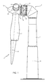
- Number 1 in Figure 1 indicates as a whole a wind turbine for producing electric power.
- wind turbine 1 is a direct-drive, variable-angular-speed type, and comprises a supporting structure 2, a nacelle 3, a hub 4, three blades 5 (only two shown in Figure 1 ), and an electric machine 6.
- Blades 5 are fitted to hub 4, in turn fitted to nacelle 3, in turn fitted to supporting structure 2.
- Supporting structure 2 is a structural member supporting nacelle 3.
- supporting structure 2 is a pylon, preferably made of ferrous material.
- nacelle 3 is mounted to rotate about an axis A1 with respect to supporting structure 2, to position blades 5 into the wind; hub 4 is mounted to rotate about an axis of rotation A2 with respect to nacelle 3; and each blade 5 is fitted to hub 4 to rotate about an axis A3 with respect to hub 4.
- Electric machine 6 comprises a stator 10, and a rotor 11 which rotates with respect to stator 10 about axis of rotation A2.
- hub 4, blades 5, and rotor 11 define a rotary assembly 12, which rotates with respect to nacelle 3 about axis of rotation A2.
- stator 10 comprises a stator cylinder 15; cooling fins 16 fixed to the outer face of stator cylinder 15; and a whole number of stator segments 18 arranged about axis of rotation A2 and fixed to the inner face of stator cylinder 15 by fastening devices not shown.
- Cooling fins 16 cool stator cylinder 15 and therefore the whole of stator 10. More specifically, cooling fins 16 and stator cylinder 15 are made of heat-conducting material, so the heat produced by Joule effect and otherwise inside stator 10 is transferred to stator cylinder 15 and from this to cooling fins 16 designed to dissipate it.
- Each stator segment 18 comprises windings, and packs of stator laminations 19 wound with a winding associated with only one stator segment 18, so that said stator segment 18 can be removed from stator 10 without interfering with the other stator segments 18.
- Stator cylinder 15 covers, protects, and supports stator segments 18.
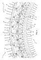
- Rotor 11 comprises a rotor cylinder 20; rotor segments 21 arranged about axis of rotation A2; and cooling fins 22 fixed to the inner face of rotor cylinder 20.
- Rotor cylinder 20 is made of nonmagnetic material and, in one embodiment of the invention, is made of aluminium or aluminium alloy.
- rotor cylinder 20 is made of nonmagnetic material, in particular stainless steel.
- rotor cylinder 20 is made of nonmagnetic material, in particular copper.
- rotor cylinder 20 is made of nonmagnetic material, in particular polymer, and preferably heat-conducting polymer material.
- Cooling fins 22 cool rotor cylinder 20 and therefore the whole of rotor 11. More specifically, cooling fins 22 and rotor cylinder 20 are made of heat-conducting nonmagnetic material, so the heat produced in rotor 11 is transferred to rotor cylinder 20 and from this to cooling fins 22 designed to dissipate it.
- each rotor segment 21 comprises a gripper 23, magnetic guides 24, magnetized modules 25, and bolts 26.
- Gripper 23 extends parallel to and radially with respect to axis of rotation A2, is fixed to rotor cylinder 20 of rotor 11 by bolts 26, is made of nonmagnetic material, and, in a preferred non-limiting embodiment of the invention, is made of aluminium or aluminium alloy.
- gripper 23 is made of nonmagnetic material, in particular stainless steel.
- gripper 23 is made of nonmagnetic material, in particular copper.
- gripper 23 is made of nonmagnetic, preferably heat-conducting polymer material.
- magnetized modules 25 are aligned radially with respect to axis of rotation A2 ( Figure 2 ) to form groups of modules 25, which in turn are arranged successively, parallel to axis of rotation A2 ( Figure 2 ), along the whole of rotor segment 21.
- each group of modules 25 comprises two modules 25 aligned radially with respect to axis of rotation A2; and, by way of a non-limiting example, each rotor segment 21 comprises eleven groups of modules 25 (not shown in the drawings) arranged successively, parallel to axis of rotation A2.
- each group of modules 25 is located between a respective pair of magnetic guides 24, each defined by respective packs of laminations made of ferromagnetic material, to guide the magnetic flux of magnetized modules 25.
- Each rotor segment 21 therefore comprises eleven pairs of magnetic guides 24.
- Each pair of magnetic guides 24 is located inside gripper 23, which is fixed to rotor cylinder 20 by bolts 26 and defines a support for the respective pair of magnetic guides 24 and the respective group of modules 25.
- Each pair of magnetic guides 24 has two faces 27, is traversed in use by the magnetic flux of magnetized modules 25, and defines the field lines.
- Group of modules 25 is protected at the top end by two insulating members 28 between magnetic guides 24, and is protected at the bottom end by an insulating member 28a between magnetic guides 24.
- the magnetic flux defined by the main frequency component of the magnetomotive force of stator 10 assists in defining the torque of electric machine 6 and converting kinetic to electric energy and vice versa, whereas the magnetic flux defined by the harmonics of the magnetomotive force of stator 10 plays no part in defining the torque of electric machine 6 and merely dissipates energy in heat.
- rotor cylinder 20, fins 22 and grippers 23 are eliminated, and rotor 11 comprises a rotor cylinder 40, arms 41, and cooling fins 42, all made of nonmagnetic material and formed integrally in one piece.
- Rotor cylinder 40 extends longitudinally, parallel to axis of rotation A2. Arms 41 extend radially, with respect to axis of rotation A2, towards stator 10, and are designed to engage magnetic guides 24, and more specifically to support magnetic guides 24 and magnetized modules 25. Arm 41 define supports for magnetized modules 25.
- Cooling fins 42 extend radially, with respect to axis of rotation A2, in the opposite direction to arms 41 and towards the centre of rotor 11, and are designed to dissipate heat from rotor cylinder 40.
- the nonmagnetic material from which rotor cylinder 40, arms 41 and cooling fins 42 are made is aluminium or aluminium alloy.
- the nonmagnetic material from which rotor cylinder 40, arms 41 and cooling fins 42 are made is a nonmagnetic, preferably heat-conducting polymer material.
- rotor 11 of aluminium, aluminium alloy or polymer material may be extruded to form rotor cylinder 40, cooling fins 42 and arms 41 simultaneously.
- the nonmagnetic material from which rotor cylinder 40, arms 41 and cooling fins 42 are made is stainless steel.
- the nonmagnetic material from which rotor cylinder 40, arms 41 and cooling fins 42 are made is copper-based.
- electric machine 6 described is a radial-flux, buried permanent magnet type
- the protective scope of the invention extends to any other type of permanent magnet electric machine, such as radial-flux surface-magnet, or axial-flux, or cross-flux electric machines.
- the wind turbine is a direct-drive type, i.e. in which the hub and electric machine rotor are connected directly.
Landscapes
- Engineering & Computer Science (AREA)
- Power Engineering (AREA)
- Combustion & Propulsion (AREA)
- Sustainable Development (AREA)
- Sustainable Energy (AREA)
- Chemical & Material Sciences (AREA)
- Life Sciences & Earth Sciences (AREA)
- Mechanical Engineering (AREA)
- General Engineering & Computer Science (AREA)
- Physics & Mathematics (AREA)
- Thermal Sciences (AREA)
- Wind Motors (AREA)
- Motor Or Generator Cooling System (AREA)
- Connection Of Motors, Electrical Generators, Mechanical Devices, And The Like (AREA)
Applications Claiming Priority (3)
| Application Number | Priority Date | Filing Date | Title |
|---|---|---|---|
| IT000374A ITMI20110374A1 (it) | 2011-03-10 | 2011-03-10 | Turbina eolica |
| EP12724386.3A EP2684278B1 (de) | 2011-03-10 | 2012-03-10 | Windturbine |
| PCT/IB2012/051133 WO2012120484A2 (en) | 2011-03-10 | 2012-03-10 | Wind turbine |
Related Parent Applications (1)
| Application Number | Title | Priority Date | Filing Date |
|---|---|---|---|
| EP12724386.3A Division EP2684278B1 (de) | 2011-03-10 | 2012-03-10 | Windturbine |
Publications (2)
| Publication Number | Publication Date |
|---|---|
| EP2942859A1 true EP2942859A1 (de) | 2015-11-11 |
| EP2942859B1 EP2942859B1 (de) | 2020-04-01 |
Family
ID=43977044
Family Applications (2)
| Application Number | Title | Priority Date | Filing Date |
|---|---|---|---|
| EP15163289.0A Active EP2942859B1 (de) | 2011-03-10 | 2012-03-10 | Elektrische maschine |
| EP12724386.3A Active EP2684278B1 (de) | 2011-03-10 | 2012-03-10 | Windturbine |
Family Applications After (1)
| Application Number | Title | Priority Date | Filing Date |
|---|---|---|---|
| EP12724386.3A Active EP2684278B1 (de) | 2011-03-10 | 2012-03-10 | Windturbine |
Country Status (6)
| Country | Link |
|---|---|
| US (1) | US20140062231A1 (de) |
| EP (2) | EP2942859B1 (de) |
| DK (1) | DK2684278T3 (de) |
| IT (1) | ITMI20110374A1 (de) |
| PL (1) | PL2684278T3 (de) |
| WO (1) | WO2012120484A2 (de) |
Families Citing this family (5)
| Publication number | Priority date | Publication date | Assignee | Title |
|---|---|---|---|---|
| ITMI20110375A1 (it) * | 2011-03-10 | 2012-09-11 | Wilic Sarl | Turbina eolica |
| ITMI20110377A1 (it) * | 2011-03-10 | 2012-09-11 | Wilic Sarl | Macchina elettrica rotante per aerogeneratore |
| ITMI20120257A1 (it) * | 2012-02-21 | 2013-08-22 | Wilic Sarl | Macchina elettrica rotante per aerogeneratore |
| DE102012208547A1 (de) * | 2012-05-22 | 2013-11-28 | Wobben Properties Gmbh | Synchrongenerator einer getriebelosen Windenergieanlage |
| DE102013106386A1 (de) | 2013-06-19 | 2014-12-24 | Dierken Engineering GmbH | Einrichtung zur Kühlung |
Citations (9)
| Publication number | Priority date | Publication date | Assignee | Title |
|---|---|---|---|---|
| GB2080707A (en) * | 1980-07-22 | 1982-02-10 | Piaggio & C Spa | Manufacture of a flywheel magneto |
| US4445062A (en) * | 1978-12-26 | 1984-04-24 | The Garrett Corporation | Rotor assembly having anchors with undulating sides |
| EP1100175A2 (de) * | 1999-11-10 | 2001-05-16 | Isuzu Motors Limited | Rotor einer rotierenden Maschine |
| WO2006017377A2 (en) * | 2004-08-06 | 2006-02-16 | Northern Power Systems, Inc. | Permanent magnet rotor for a direct drive generator or a low speed motor |
| US20060255679A1 (en) * | 2005-05-13 | 2006-11-16 | Dine Pieter V | Apparatus for pole pieces |
| WO2007063370A1 (en) * | 2005-11-29 | 2007-06-07 | High Technology Investments, B.V. | Magnet holder for permanent magnet rotors of rotating machines |
| WO2009091248A2 (en) * | 2008-01-16 | 2009-07-23 | Lagerwey Wind Bv | Generator for direct drive wind turbine |
| DE102009025929A1 (de) * | 2009-06-05 | 2010-12-09 | Ulrich Spevacek | Läuferaufbau für eine permanentmagneterregte, rotierende elektrische Maschine |
| EP2282397A1 (de) * | 2009-08-07 | 2011-02-09 | Wilic S.Àr.L. | Verfahren und Vorrichtung zur Aktivierung einer elektrischen Maschine und elektrische Maschine |
Family Cites Families (1)
| Publication number | Priority date | Publication date | Assignee | Title |
|---|---|---|---|---|
| JP3955865B2 (ja) * | 2004-11-12 | 2007-08-08 | 三菱電機株式会社 | 磁石発電機 |
-
2011
- 2011-03-10 IT IT000374A patent/ITMI20110374A1/it unknown
-
2012
- 2012-03-10 EP EP15163289.0A patent/EP2942859B1/de active Active
- 2012-03-10 PL PL12724386T patent/PL2684278T3/pl unknown
- 2012-03-10 EP EP12724386.3A patent/EP2684278B1/de active Active
- 2012-03-10 US US14/003,739 patent/US20140062231A1/en not_active Abandoned
- 2012-03-10 WO PCT/IB2012/051133 patent/WO2012120484A2/en active Application Filing
- 2012-03-10 DK DK12724386.3T patent/DK2684278T3/en active
Patent Citations (9)
| Publication number | Priority date | Publication date | Assignee | Title |
|---|---|---|---|---|
| US4445062A (en) * | 1978-12-26 | 1984-04-24 | The Garrett Corporation | Rotor assembly having anchors with undulating sides |
| GB2080707A (en) * | 1980-07-22 | 1982-02-10 | Piaggio & C Spa | Manufacture of a flywheel magneto |
| EP1100175A2 (de) * | 1999-11-10 | 2001-05-16 | Isuzu Motors Limited | Rotor einer rotierenden Maschine |
| WO2006017377A2 (en) * | 2004-08-06 | 2006-02-16 | Northern Power Systems, Inc. | Permanent magnet rotor for a direct drive generator or a low speed motor |
| US20060255679A1 (en) * | 2005-05-13 | 2006-11-16 | Dine Pieter V | Apparatus for pole pieces |
| WO2007063370A1 (en) * | 2005-11-29 | 2007-06-07 | High Technology Investments, B.V. | Magnet holder for permanent magnet rotors of rotating machines |
| WO2009091248A2 (en) * | 2008-01-16 | 2009-07-23 | Lagerwey Wind Bv | Generator for direct drive wind turbine |
| DE102009025929A1 (de) * | 2009-06-05 | 2010-12-09 | Ulrich Spevacek | Läuferaufbau für eine permanentmagneterregte, rotierende elektrische Maschine |
| EP2282397A1 (de) * | 2009-08-07 | 2011-02-09 | Wilic S.Àr.L. | Verfahren und Vorrichtung zur Aktivierung einer elektrischen Maschine und elektrische Maschine |
Also Published As
| Publication number | Publication date |
|---|---|
| EP2684278B1 (de) | 2015-05-06 |
| EP2684278A2 (de) | 2014-01-15 |
| WO2012120484A3 (en) | 2012-11-15 |
| EP2942859B1 (de) | 2020-04-01 |
| DK2684278T3 (en) | 2015-07-27 |
| US20140062231A1 (en) | 2014-03-06 |
| PL2684278T3 (pl) | 2015-10-30 |
| WO2012120484A2 (en) | 2012-09-13 |
| ITMI20110374A1 (it) | 2012-09-11 |
Similar Documents
| Publication | Publication Date | Title |
|---|---|---|
| US9006918B2 (en) | Wind turbine | |
| EP1641101B1 (de) | Elektrische Maschine mit doppelseitigem Stator | |
| US7692357B2 (en) | Electrical machines and assemblies including a yokeless stator with modular lamination stacks | |
| EP1641102B1 (de) | Elektrische Maschine mit doppelseitigem Blechpaket | |
| US7619332B2 (en) | Permanent magnet type electric rotating machine and wind turbine electric power generation system | |
| EP2942859B1 (de) | Elektrische maschine | |
| CA2769128C (en) | Electrical machine, in particular an electrical generator | |
| CN102315741A (zh) | 一种采用模块化非晶合金定子的轴向永磁电机 | |
| CN103283126A (zh) | 飞行器 | |
| CN101557150A (zh) | 无铁芯永磁同步直驱风力发电机 | |
| EP3021458A1 (de) | Rotor einer Windturbine | |
| EP2713480B1 (de) | Rotor eines Permanentmagnetgenerators | |
| EP2445087B1 (de) | Generator, insbesondere für eine Windturbine | |
| EP2939328B1 (de) | Elektrische maschine | |
| EP2761173B1 (de) | Luftkühlung eines windturbinengenerators | |
| CN102299599A (zh) | 一种定子永磁体高速电机 | |
| EP3352336A1 (de) | Elektrische drehmaschine und windkrafterzeugungssystem | |
| US20240154510A1 (en) | Magnetic geared rotating machine and power generation system | |
| Qu et al. | Electrical machines and assemblies including a yokeless stator with modular lamination stacks | |
| CN201038962Y (zh) | 一种永磁风力发电机 |
Legal Events
| Date | Code | Title | Description |
|---|---|---|---|
| PUAI | Public reference made under article 153(3) epc to a published international application that has entered the european phase |
Free format text: ORIGINAL CODE: 0009012 |
|
| AC | Divisional application: reference to earlier application |
Ref document number: 2684278 Country of ref document: EP Kind code of ref document: P |
|
| AK | Designated contracting states |
Kind code of ref document: A1 Designated state(s): AL AT BE BG CH CY CZ DE DK EE ES FI FR GB GR HR HU IE IS IT LI LT LU LV MC MK MT NL NO PL PT RO RS SE SI SK SM TR |
|
| 17P | Request for examination filed |
Effective date: 20160511 |
|
| RBV | Designated contracting states (corrected) |
Designated state(s): AL AT BE BG CH CY CZ DE DK EE ES FI FR GB GR HR HU IE IS IT LI LT LU LV MC MK MT NL NO PL PT RO RS SE SI SK SM TR |
|
| STAA | Information on the status of an ep patent application or granted ep patent |
Free format text: STATUS: EXAMINATION IS IN PROGRESS |
|
| 17Q | First examination report despatched |
Effective date: 20170201 |
|
| GRAP | Despatch of communication of intention to grant a patent |
Free format text: ORIGINAL CODE: EPIDOSNIGR1 |
|
| STAA | Information on the status of an ep patent application or granted ep patent |
Free format text: STATUS: GRANT OF PATENT IS INTENDED |
|
| RIC1 | Information provided on ipc code assigned before grant |
Ipc: H02K 1/27 20060101AFI20190930BHEP Ipc: H02K 1/30 20060101ALI20190930BHEP Ipc: H02K 7/18 20060101ALN20190930BHEP Ipc: H02K 5/18 20060101ALI20190930BHEP Ipc: F03D 9/00 20160101ALN20190930BHEP |
|
| INTG | Intention to grant announced |
Effective date: 20191021 |
|
| GRAS | Grant fee paid |
Free format text: ORIGINAL CODE: EPIDOSNIGR3 |
|
| GRAA | (expected) grant |
Free format text: ORIGINAL CODE: 0009210 |
|
| STAA | Information on the status of an ep patent application or granted ep patent |
Free format text: STATUS: THE PATENT HAS BEEN GRANTED |
|
| AC | Divisional application: reference to earlier application |
Ref document number: 2684278 Country of ref document: EP Kind code of ref document: P |
|
| AK | Designated contracting states |
Kind code of ref document: B1 Designated state(s): AL AT BE BG CH CY CZ DE DK EE ES FI FR GB GR HR HU IE IS IT LI LT LU LV MC MK MT NL NO PL PT RO RS SE SI SK SM TR |
|
| REG | Reference to a national code |
Ref country code: GB Ref legal event code: FG4D |
|
| REG | Reference to a national code |
Ref country code: CH Ref legal event code: EP Ref country code: AT Ref legal event code: REF Ref document number: 1252630 Country of ref document: AT Kind code of ref document: T Effective date: 20200415 |
|
| REG | Reference to a national code |
Ref country code: DE Ref legal event code: R096 Ref document number: 602012069013 Country of ref document: DE |
|
| REG | Reference to a national code |
Ref country code: IE Ref legal event code: FG4D |
|
| PG25 | Lapsed in a contracting state [announced via postgrant information from national office to epo] |
Ref country code: BG Free format text: LAPSE BECAUSE OF FAILURE TO SUBMIT A TRANSLATION OF THE DESCRIPTION OR TO PAY THE FEE WITHIN THE PRESCRIBED TIME-LIMIT Effective date: 20200701 |
|
| REG | Reference to a national code |
Ref country code: NL Ref legal event code: MP Effective date: 20200401 |
|
| REG | Reference to a national code |
Ref country code: LT Ref legal event code: MG4D |
|
| PG25 | Lapsed in a contracting state [announced via postgrant information from national office to epo] |
Ref country code: CZ Free format text: LAPSE BECAUSE OF FAILURE TO SUBMIT A TRANSLATION OF THE DESCRIPTION OR TO PAY THE FEE WITHIN THE PRESCRIBED TIME-LIMIT Effective date: 20200401 Ref country code: NL Free format text: LAPSE BECAUSE OF FAILURE TO SUBMIT A TRANSLATION OF THE DESCRIPTION OR TO PAY THE FEE WITHIN THE PRESCRIBED TIME-LIMIT Effective date: 20200401 Ref country code: LT Free format text: LAPSE BECAUSE OF FAILURE TO SUBMIT A TRANSLATION OF THE DESCRIPTION OR TO PAY THE FEE WITHIN THE PRESCRIBED TIME-LIMIT Effective date: 20200401 Ref country code: PT Free format text: LAPSE BECAUSE OF FAILURE TO SUBMIT A TRANSLATION OF THE DESCRIPTION OR TO PAY THE FEE WITHIN THE PRESCRIBED TIME-LIMIT Effective date: 20200817 Ref country code: GR Free format text: LAPSE BECAUSE OF FAILURE TO SUBMIT A TRANSLATION OF THE DESCRIPTION OR TO PAY THE FEE WITHIN THE PRESCRIBED TIME-LIMIT Effective date: 20200702 Ref country code: NO Free format text: LAPSE BECAUSE OF FAILURE TO SUBMIT A TRANSLATION OF THE DESCRIPTION OR TO PAY THE FEE WITHIN THE PRESCRIBED TIME-LIMIT Effective date: 20200701 Ref country code: SE Free format text: LAPSE BECAUSE OF FAILURE TO SUBMIT A TRANSLATION OF THE DESCRIPTION OR TO PAY THE FEE WITHIN THE PRESCRIBED TIME-LIMIT Effective date: 20200401 Ref country code: IS Free format text: LAPSE BECAUSE OF FAILURE TO SUBMIT A TRANSLATION OF THE DESCRIPTION OR TO PAY THE FEE WITHIN THE PRESCRIBED TIME-LIMIT Effective date: 20200801 Ref country code: FI Free format text: LAPSE BECAUSE OF FAILURE TO SUBMIT A TRANSLATION OF THE DESCRIPTION OR TO PAY THE FEE WITHIN THE PRESCRIBED TIME-LIMIT Effective date: 20200401 |
|
| REG | Reference to a national code |
Ref country code: AT Ref legal event code: MK05 Ref document number: 1252630 Country of ref document: AT Kind code of ref document: T Effective date: 20200401 |
|
| PG25 | Lapsed in a contracting state [announced via postgrant information from national office to epo] |
Ref country code: HR Free format text: LAPSE BECAUSE OF FAILURE TO SUBMIT A TRANSLATION OF THE DESCRIPTION OR TO PAY THE FEE WITHIN THE PRESCRIBED TIME-LIMIT Effective date: 20200401 Ref country code: LV Free format text: LAPSE BECAUSE OF FAILURE TO SUBMIT A TRANSLATION OF THE DESCRIPTION OR TO PAY THE FEE WITHIN THE PRESCRIBED TIME-LIMIT Effective date: 20200401 Ref country code: RS Free format text: LAPSE BECAUSE OF FAILURE TO SUBMIT A TRANSLATION OF THE DESCRIPTION OR TO PAY THE FEE WITHIN THE PRESCRIBED TIME-LIMIT Effective date: 20200401 |
|
| PG25 | Lapsed in a contracting state [announced via postgrant information from national office to epo] |
Ref country code: AL Free format text: LAPSE BECAUSE OF FAILURE TO SUBMIT A TRANSLATION OF THE DESCRIPTION OR TO PAY THE FEE WITHIN THE PRESCRIBED TIME-LIMIT Effective date: 20200401 |
|
| REG | Reference to a national code |
Ref country code: DE Ref legal event code: R097 Ref document number: 602012069013 Country of ref document: DE |
|
| PG25 | Lapsed in a contracting state [announced via postgrant information from national office to epo] |
Ref country code: SM Free format text: LAPSE BECAUSE OF FAILURE TO SUBMIT A TRANSLATION OF THE DESCRIPTION OR TO PAY THE FEE WITHIN THE PRESCRIBED TIME-LIMIT Effective date: 20200401 Ref country code: EE Free format text: LAPSE BECAUSE OF FAILURE TO SUBMIT A TRANSLATION OF THE DESCRIPTION OR TO PAY THE FEE WITHIN THE PRESCRIBED TIME-LIMIT Effective date: 20200401 Ref country code: RO Free format text: LAPSE BECAUSE OF FAILURE TO SUBMIT A TRANSLATION OF THE DESCRIPTION OR TO PAY THE FEE WITHIN THE PRESCRIBED TIME-LIMIT Effective date: 20200401 Ref country code: ES Free format text: LAPSE BECAUSE OF FAILURE TO SUBMIT A TRANSLATION OF THE DESCRIPTION OR TO PAY THE FEE WITHIN THE PRESCRIBED TIME-LIMIT Effective date: 20200401 Ref country code: AT Free format text: LAPSE BECAUSE OF FAILURE TO SUBMIT A TRANSLATION OF THE DESCRIPTION OR TO PAY THE FEE WITHIN THE PRESCRIBED TIME-LIMIT Effective date: 20200401 Ref country code: DK Free format text: LAPSE BECAUSE OF FAILURE TO SUBMIT A TRANSLATION OF THE DESCRIPTION OR TO PAY THE FEE WITHIN THE PRESCRIBED TIME-LIMIT Effective date: 20200401 |
|
| PLBE | No opposition filed within time limit |
Free format text: ORIGINAL CODE: 0009261 |
|
| STAA | Information on the status of an ep patent application or granted ep patent |
Free format text: STATUS: NO OPPOSITION FILED WITHIN TIME LIMIT |
|
| PG25 | Lapsed in a contracting state [announced via postgrant information from national office to epo] |
Ref country code: PL Free format text: LAPSE BECAUSE OF FAILURE TO SUBMIT A TRANSLATION OF THE DESCRIPTION OR TO PAY THE FEE WITHIN THE PRESCRIBED TIME-LIMIT Effective date: 20200401 Ref country code: SK Free format text: LAPSE BECAUSE OF FAILURE TO SUBMIT A TRANSLATION OF THE DESCRIPTION OR TO PAY THE FEE WITHIN THE PRESCRIBED TIME-LIMIT Effective date: 20200401 |
|
| 26N | No opposition filed |
Effective date: 20210112 |
|
| PG25 | Lapsed in a contracting state [announced via postgrant information from national office to epo] |
Ref country code: SI Free format text: LAPSE BECAUSE OF FAILURE TO SUBMIT A TRANSLATION OF THE DESCRIPTION OR TO PAY THE FEE WITHIN THE PRESCRIBED TIME-LIMIT Effective date: 20200401 |
|
| PG25 | Lapsed in a contracting state [announced via postgrant information from national office to epo] |
Ref country code: MC Free format text: LAPSE BECAUSE OF FAILURE TO SUBMIT A TRANSLATION OF THE DESCRIPTION OR TO PAY THE FEE WITHIN THE PRESCRIBED TIME-LIMIT Effective date: 20200401 |
|
| REG | Reference to a national code |
Ref country code: CH Ref legal event code: PL |
|
| GBPC | Gb: european patent ceased through non-payment of renewal fee |
Effective date: 20210310 |
|
| REG | Reference to a national code |
Ref country code: BE Ref legal event code: MM Effective date: 20210331 |
|
| PG25 | Lapsed in a contracting state [announced via postgrant information from national office to epo] |
Ref country code: GB Free format text: LAPSE BECAUSE OF NON-PAYMENT OF DUE FEES Effective date: 20210310 Ref country code: IE Free format text: LAPSE BECAUSE OF NON-PAYMENT OF DUE FEES Effective date: 20210310 Ref country code: LI Free format text: LAPSE BECAUSE OF NON-PAYMENT OF DUE FEES Effective date: 20210331 Ref country code: LU Free format text: LAPSE BECAUSE OF NON-PAYMENT OF DUE FEES Effective date: 20210310 Ref country code: CH Free format text: LAPSE BECAUSE OF NON-PAYMENT OF DUE FEES Effective date: 20210331 |
|
| PG25 | Lapsed in a contracting state [announced via postgrant information from national office to epo] |
Ref country code: BE Free format text: LAPSE BECAUSE OF NON-PAYMENT OF DUE FEES Effective date: 20210331 |
|
| REG | Reference to a national code |
Ref country code: FR Ref legal event code: PLFP Year of fee payment: 12 |
|
| PGFP | Annual fee paid to national office [announced via postgrant information from national office to epo] |
Ref country code: FR Payment date: 20230323 Year of fee payment: 12 |
|
| PG25 | Lapsed in a contracting state [announced via postgrant information from national office to epo] |
Ref country code: HU Free format text: LAPSE BECAUSE OF FAILURE TO SUBMIT A TRANSLATION OF THE DESCRIPTION OR TO PAY THE FEE WITHIN THE PRESCRIBED TIME-LIMIT; INVALID AB INITIO Effective date: 20120310 Ref country code: CY Free format text: LAPSE BECAUSE OF FAILURE TO SUBMIT A TRANSLATION OF THE DESCRIPTION OR TO PAY THE FEE WITHIN THE PRESCRIBED TIME-LIMIT Effective date: 20200401 |
|
| PGFP | Annual fee paid to national office [announced via postgrant information from national office to epo] |
Ref country code: TR Payment date: 20230217 Year of fee payment: 12 Ref country code: IT Payment date: 20230313 Year of fee payment: 12 |
|
| P01 | Opt-out of the competence of the unified patent court (upc) registered |
Effective date: 20230518 |
|
| PG25 | Lapsed in a contracting state [announced via postgrant information from national office to epo] |
Ref country code: MK Free format text: LAPSE BECAUSE OF FAILURE TO SUBMIT A TRANSLATION OF THE DESCRIPTION OR TO PAY THE FEE WITHIN THE PRESCRIBED TIME-LIMIT Effective date: 20200401 |
|
| PGFP | Annual fee paid to national office [announced via postgrant information from national office to epo] |
Ref country code: DE Payment date: 20240328 Year of fee payment: 13 |