EP2942595A1 - Heat exchanging apparatus and air conditioning apparatus - Google Patents
Heat exchanging apparatus and air conditioning apparatus Download PDFInfo
- Publication number
- EP2942595A1 EP2942595A1 EP15160937.7A EP15160937A EP2942595A1 EP 2942595 A1 EP2942595 A1 EP 2942595A1 EP 15160937 A EP15160937 A EP 15160937A EP 2942595 A1 EP2942595 A1 EP 2942595A1
- Authority
- EP
- European Patent Office
- Prior art keywords
- groove
- grooves
- fin
- heat exchanging
- width
- Prior art date
- Legal status (The legal status is an assumption and is not a legal conclusion. Google has not performed a legal analysis and makes no representation as to the accuracy of the status listed.)
- Granted
Links
Images










Classifications
-
- F—MECHANICAL ENGINEERING; LIGHTING; HEATING; WEAPONS; BLASTING
- F28—HEAT EXCHANGE IN GENERAL
- F28F—DETAILS OF HEAT-EXCHANGE AND HEAT-TRANSFER APPARATUS, OF GENERAL APPLICATION
- F28F13/00—Arrangements for modifying heat-transfer, e.g. increasing, decreasing
- F28F13/18—Arrangements for modifying heat-transfer, e.g. increasing, decreasing by applying coatings, e.g. radiation-absorbing, radiation-reflecting; by surface treatment, e.g. polishing
- F28F13/185—Heat-exchange surfaces provided with microstructures or with porous coatings
- F28F13/187—Heat-exchange surfaces provided with microstructures or with porous coatings especially adapted for evaporator surfaces or condenser surfaces, e.g. with nucleation sites
-
- F—MECHANICAL ENGINEERING; LIGHTING; HEATING; WEAPONS; BLASTING
- F28—HEAT EXCHANGE IN GENERAL
- F28F—DETAILS OF HEAT-EXCHANGE AND HEAT-TRANSFER APPARATUS, OF GENERAL APPLICATION
- F28F1/00—Tubular elements; Assemblies of tubular elements
- F28F1/10—Tubular elements and assemblies thereof with means for increasing heat-transfer area, e.g. with fins, with projections, with recesses
- F28F1/12—Tubular elements and assemblies thereof with means for increasing heat-transfer area, e.g. with fins, with projections, with recesses the means being only outside the tubular element
- F28F1/24—Tubular elements and assemblies thereof with means for increasing heat-transfer area, e.g. with fins, with projections, with recesses the means being only outside the tubular element and extending transversely
- F28F1/32—Tubular elements and assemblies thereof with means for increasing heat-transfer area, e.g. with fins, with projections, with recesses the means being only outside the tubular element and extending transversely the means having portions engaging further tubular elements
-
- F—MECHANICAL ENGINEERING; LIGHTING; HEATING; WEAPONS; BLASTING
- F28—HEAT EXCHANGE IN GENERAL
- F28F—DETAILS OF HEAT-EXCHANGE AND HEAT-TRANSFER APPARATUS, OF GENERAL APPLICATION
- F28F17/00—Removing ice or water from heat-exchange apparatus
- F28F17/005—Means for draining condensates from heat exchangers, e.g. from evaporators
-
- F—MECHANICAL ENGINEERING; LIGHTING; HEATING; WEAPONS; BLASTING
- F28—HEAT EXCHANGE IN GENERAL
- F28D—HEAT-EXCHANGE APPARATUS, NOT PROVIDED FOR IN ANOTHER SUBCLASS, IN WHICH THE HEAT-EXCHANGE MEDIA DO NOT COME INTO DIRECT CONTACT
- F28D1/00—Heat-exchange apparatus having stationary conduit assemblies for one heat-exchange medium only, the media being in contact with different sides of the conduit wall, in which the other heat-exchange medium is a large body of fluid, e.g. domestic or motor car radiators
- F28D1/02—Heat-exchange apparatus having stationary conduit assemblies for one heat-exchange medium only, the media being in contact with different sides of the conduit wall, in which the other heat-exchange medium is a large body of fluid, e.g. domestic or motor car radiators with heat-exchange conduits immersed in the body of fluid
- F28D1/04—Heat-exchange apparatus having stationary conduit assemblies for one heat-exchange medium only, the media being in contact with different sides of the conduit wall, in which the other heat-exchange medium is a large body of fluid, e.g. domestic or motor car radiators with heat-exchange conduits immersed in the body of fluid with tubular conduits
- F28D1/047—Heat-exchange apparatus having stationary conduit assemblies for one heat-exchange medium only, the media being in contact with different sides of the conduit wall, in which the other heat-exchange medium is a large body of fluid, e.g. domestic or motor car radiators with heat-exchange conduits immersed in the body of fluid with tubular conduits the conduits being bent, e.g. in a serpentine or zig-zag
-
- F—MECHANICAL ENGINEERING; LIGHTING; HEATING; WEAPONS; BLASTING
- F28—HEAT EXCHANGE IN GENERAL
- F28F—DETAILS OF HEAT-EXCHANGE AND HEAT-TRANSFER APPARATUS, OF GENERAL APPLICATION
- F28F2245/00—Coatings; Surface treatments
- F28F2245/04—Coatings; Surface treatments hydrophobic
-
- F—MECHANICAL ENGINEERING; LIGHTING; HEATING; WEAPONS; BLASTING
- F28—HEAT EXCHANGE IN GENERAL
- F28F—DETAILS OF HEAT-EXCHANGE AND HEAT-TRANSFER APPARATUS, OF GENERAL APPLICATION
- F28F2255/00—Heat exchanger elements made of materials having special features or resulting from particular manufacturing processes
- F28F2255/20—Heat exchanger elements made of materials having special features or resulting from particular manufacturing processes with nanostructures
Definitions
- the present invention relates to a heat exchanging apparatus and an air conditioning apparatus.
- a heat exchanging apparatus configuring an air conditioning apparatus includes a tube inside which a refrigerant flows and a fin thermally coupled to the tube, and performs heat exchange between the refrigerant inside the tube and air passing through between the fins.
- a coating is performed on a surface of the fin for giving hydrophilicity or water repellency to the fin, in order to prevent decrease of efficiency with increase of ventilation resistance between the fins due to dew condensation and frost formation on the fin of the heat exchanging apparatus, or to prevent water splashes from the fin to an air conditioner space.
- the fin is typically made of aluminum, and a surface of an aluminum material shows slight hydrophilicity, but it is desirable that the fin has higher hydrophilicity or sufficient water repellency.
- water repellency or hydrophilicity depends on chemical properties and surface roughness of a material. It has been known that as surface roughness increases by forming small unevenness on the surface, the surface of the material shows higher hydrophilicity or water repellency (Wenzel's equation).
- Patent Literature 1 an uneven structure is formed on a surface of an aluminum member (fin) by soaking the fin in acid, and then a water repellency coating is performed thereon using a fluorine-based resin material, so that the fin has higher water repellency than that of the fin on which the water repellency coating is only performed.
- a coating of a fin of a heat exchanging apparatus is performed by soaking in a coating liquid a sheet material forming the fin, or an assembly in which the fin and a tube are fit together. Therefore, in order to perform the coating, a liquid tank fit for a size of the fin for storing the coating liquid and the coating liquid that fills the liquid tank are necessary, which increases cost corresponding to the coating liquid and the liquid tank.
- the coating step is necessary. Before the coating, acid cleaning, water washing, a conversion coating of a base and the like are necessary, and after the coating, burning is performed, which increase steps and also take time. In particular, when the coating is performed on a fin of a heat exchanger disposed outdoors, it is difficult to secure durability of the coating which can withstand long-term use.
- the present invention has been made in view of the above problems, and an object thereof is to provide a heat exchanging apparatus that suppresses the problem of increasing ventilation resistance due to dew condensation and frost formation on the fin by giving the sufficient water repellency to the surface of the fin without performing the coating, and an air conditioning apparatus including the heat exchanging apparatus.
- the present invention adopts the following solutions.
- a heat exchanging apparatus includes: a plurality of fins each having a plate shape and extending in a vertical direction, the plurality of fins being arranged successively in a horizontal direction in a state that surfaces of the adjacent pair of fins are parallel to each other; and a heat transfer tube inside which a refrigerant flows, the heat transfer tube being inserted into a tube hole provided on each of the plurality of fins while adhering.
- a plurality of grooves each extending from a upper part to a lower part is formed on the surface of each of the fins at intervals in an arrangement direction orthogonal to the extending direction of each of the grooves, and a width of each of the grooves is 5 ⁇ m or more to 200 ⁇ m or less and a distance between edges of the adjacent grooves in the arrangement direction is 5 ⁇ m or more to twice or less the width of each of the grooves.
- the width of each of the grooves formed on the surface of each of the plate shape fins at intervals in the arrangement direction is 5 ⁇ m or more to 200 ⁇ m or less.
- a size of a waterdrop formed on the surface of the fin is 1 mm or more to 3 mm or less, the width of the groove is sufficiently narrower than the size of the waterdrop. Therefore, a phenomenon (bridge phenomenon) occurs, the bridge phenomenon being the phenomenon in which the waterdrop formed on an upper part of the groove does not reach a bottom of the groove and is disposed to extend over the groove from one edge to the other edge.
- the water repellency of the surface of the fin becomes higher because the bridge phenomenon occurs.
- the distance between the edges of the adjacent grooves is 5 ⁇ m or more to twice or less the width of each of the grooves.
- the size of the waterdrop formed on the surface of the fin is 1 mm or more to 3 mm or less in diameter, the distance between the edges of the grooves is sufficiently smaller than the size of the waterdrop. Therefore, the surface of the fin between the edges of the grooves shows the sufficient water repellency.
- the present invention can provide the heat exchanging apparatus that suppresses a problem of increasing ventilation resistance due to dew condensation and frost formation on the fin by giving the sufficient water repellency to the surface of the fin without performing a coating.
- a contact angle formed between the surface of each of the fins and the waterdrop is ⁇ e
- the water repellency is sufficiently shown.
- the ratio of the depth of the groove to the width of the groove corresponds to 1/tan ⁇ e
- the water repellency is sufficiently shown.
- a ratio of a depth of each of the grooves to the width of each of the grooves is 1/tan ⁇ e or more.
- the sufficient water repellency can be given to the surface of the fin.
- the sufficient water repellency can certainly be given to the surface of the fin.
- a cross section shape of each of the grooves may be rectangular in a plane orthogonal to the extending direction.
- the sufficient water repellency can be given to the surface of the fin on which the plurality of grooves each having the rectangular cross section is formed.
- each of the plurality of grooves extends from the upper part to the lower part along a vertical direction.
- the waterdrop formed on the surface of the fin to which the water repellency is given can certainly be dripped toward the lower part of the fin by its own weight along the groove formed from the upper part to the lower part in the vertical direction.
- each of the plurality of grooves extends from the upper part to the lower part along a direction inclined from a vertical direction.
- the waterdrop formed on the surface of the fin to which the water repellency is given can certainly be dripped toward the lower part of the fin by its own weight along the groove formed from the upper part to the lower part in the direction inclined from the vertical direction.
- An air conditioning apparatus of the present invention includes the heat exchanging apparatus according to any one of the first to fifth aspects; and a fan introducing air toward the heat exchanging apparatus.
- each of the plurality of grooves extends from the upper part to the lower part along a direction inclined from a vertical direction, and extends in a direction descending from an upstream side to a downstream side of a flowing direction of the air introduced with the fan.
- the waterdrop formed on the surface of the fin to which the water repellency is given can be dripped by its own weight along the groove formed from the upper part to the lower part in the direction inclined from the vertical direction. Further, the waterdrop formed on the surface of the fin can be dripped along the groove by the air introduced with the fan.
- the waterdrop formed on the surface of the fin can be certainly dripped by action of its own weight and the air introduced with the fan.
- the present invention can provide a heat exchanging apparatus that suppresses a problem of increasing ventilation resistance due to dew condensation and frost formation on a fin by giving sufficient water repellency to a surface of the fin without performing a coating.
- the air conditioning apparatus 100 of the first embodiment includes an indoor unit 20 and an outdoor unit 30.
- a refrigerant flows from the indoor unit 20 into the outdoor unit 30, or from the outdoor unit 30 into the indoor unit 20 through a pair of refrigerant piping 40.
- the indoor unit 20 and the outdoor unit 30 are electrically connected to each other with electrical wiring (not illustrated).
- the indoor unit 20 includes a rear surface base (not illustrated) and a front surface panel 21 which are integrally configured.
- An indoor heat exchanging apparatus 22 of a plate fin tube type, an indoor fan 23 having a substantially cylindrical shape, and a control part 24 controlling operation of the indoor unit 20 are fitted to the base.
- the outdoor unit 30 includes a casing 31.
- An outdoor heat exchanging apparatus 32 heat exchanging apparatus
- a propeller fan 33 fan
- a compressor 34 compressor
- an outdoor unit electrical equipment box 50 are provided inside the casing 31.
- the outdoor unit 30 is provided with a baffle plate 35 on a substantially center position, the baffle plate 35 separating the inside of the outdoor unit 30 into two spaces.
- the propeller fan 33 is disposed on the left space and the compressor 34 is disposed on the right space when the outdoor unit 30 is viewed from the front.
- the propeller fan 33 rotates counterclockwise when the outdoor unit 30 is viewed from the front, and generates airflow inside the casing 31 in a direction from the rear surface to the front surface (direction indicated by an arrow in Fig. 2 ).
- the propeller fan 33 is a device that introduces outside air (air) toward the outdoor heat exchanging apparatus 32 in this manner.
- a fin guard (not illustrated) and a fan guard 36 are provided on the rear surface of the casing 31 from which the outdoor heat exchanging apparatus 32 faces the outside, and on the front surface of the casing 31 from which the propeller fan 33 faces the outside, respectively.
- the fin guard is provided for preventing the fins 10 being damaged by unexpected impact from the outside.
- the fan guard 36 is provided for protecting the propeller fan 33 from impact from the outside and also preventing dust included in outside air from coming into the inside of the casing 31.
- the compressor 34 changes a gas refrigerant having a low temperature and pressure into a gas refrigerant having a high temperature and pressure and then discharges it.
- a refrigerant circuit includes the compressor 34, the indoor heat exchanging apparatus 22, the outdoor heat exchanging apparatus 32, the refrigerant piping 40, an expansion valve (not illustrated), a four-way valve controlling the flowing direction of the refrigerant (not illustrated) and the like.
- the refrigerant circuit is a circuit circulating the refrigerant between the indoor unit 20 and the outdoor unit 30 through the pair of refrigerant piping 40.
- the gas refrigerant having the high temperature and pressure in the compressor 34 is pressure-fed to the indoor heat exchanging apparatus 22 of the indoor unit 20 through the refrigerant piping 40 illustrated in Fig. 1 .
- the refrigerant having the high temperature and pressure and flowing through the indoor heat exchanging apparatus 22 gives heat to indoor air taken with the indoor fan 23.
- hot air that is air to which the heat is given, is blown from an air outlet 21c.
- the gas refrigerant having the high temperature and pressure is condensed to be liquefied by the heat exchange in the indoor heat exchanging apparatus 22, and becomes a liquid refrigerant having a high temperature and pressure.
- the liquid refrigerant having the high temperature and pressure is decompressed with the expansion valve while being fed to the outdoor heat exchanging apparatus 32 of the outdoor unit 30, and has a low temperature and pressure.
- the liquid refrigerant having the low temperature and pressure and flowing through the outdoor heat exchanging apparatus 32 takes heat from air newly taken from the outside into the inside of the casing 31 with the propeller fan 33.
- the liquid refrigerant having the low temperature and pressure is evaporated to be gasified, and becomes a gas refrigerant having a low temperature and pressure.
- the gas refrigerant having the low temperature and pressure is fed to the compressor 34 to have a high temperature and pressure.
- the air conditioning apparatus 100 performs the heating operation by repeating the above steps.
- the refrigerant flows in the refrigerant circuit in a direction opposite to the direction during the heating operation. That is, the gas refrigerant having the high temperature and pressure in the compressor 34 is pressure-fed to the outdoor heat exchanging apparatus 32 through the refrigerant piping 40.
- outdoor air takes heat from the gas refrigerant, so that the gas refrigerant is condensed to be liquefied.
- the gas refrigerant having the high temperature and pressure becomes a liquid refrigerant having a high temperature and pressure.
- the liquid refrigerant having the high temperature and pressure is decompressed with the expansion valve to have a low temperature and pressure, and is fed to the indoor heat exchanging apparatus 22 through the refrigerant piping 40 again.
- the liquid refrigerant having the low temperature and pressure takes heat from indoor air, and then cool air is blown from the air outlet 21c and the refrigerant itself is evaporated to be gasified.
- the liquid refrigerant having the low temperature and pressure becomes a gas refrigerant having a low temperature and pressure.
- the gas refrigerant is fed to the compressor 34 again to have a high temperature and pressure.
- the air conditioning apparatus 100 performs the cooling operation by repeating the above steps.
- the outdoor heat exchanging apparatus 32 of this embodiment is a fin and tube type heat exchanging apparatus.
- the outdoor heat exchanging apparatus 32 is provided with a plurality of fins 10 each having a plate shape extending along an axis X extending in a vertical direction.
- the plurality of fins 10 is arranged successively in a horizontal direction in a state that surfaces of the adjacent pair of fins 10 are parallel to each other.
- reference numeral 10 is given to the only two fins, and is not given to the other fins to omit the description thereof.
- the plurality of fins 10 is arranged such that it does not disturb the flowing of the air introduced with the propeller fan 33 and can transfer heat efficiently to the introduced air.
- each of the fins 10 is provided with tube holes 10B, and a heat transfer tube 40A is inserted into each of the tube holes 10B.
- the heat transfer tube 40A is a part of the refrigerant piping 40, and is a component through which the refrigerant flows in the outdoor heat exchanging apparatus 32.
- the heat transfer tube 40A is inserted into the tube hole 10B while adhering, and the refrigerant (liquid) flows thereinside.
- the fin 10 is made of a metallic material having high heat transfer ability. Therefore, the fin 10 can transfer the heat having transferred from the refrigerant to air around the fin 10 efficiently.
- the metallic material forming the fin 10 for example, an aluminum material, an aluminum material on which a conversion coating is performed, or a stainless steel material can be used.
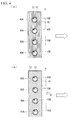
- arrows in Figs. 4(a) and (b) each indicate a flowing direction of the air introduced with the propeller fan 33.
- reference numeral 12 is given to the only two grooves, and is not given to the other grooves to omit the description thereof.
- the surface of the fin 10 is formed with the plurality of grooves 12 each extending from an upper part to a lower part along an axis X extending in a vertical direction.
- the plurality of grooves 12 is formed at fixed intervals in an arrangement direction orthogonal to the extending direction of the groove 12 (axis x direction).
- the grooves 12 are provided in order to prevent waterdrops attached to the surface of the fin 10 forming a large lump to cause dew condensation and frost formation. More specifically, the grooves 12 are provided for making the surface of the fin 10 show sufficient water repellency and making the waterdrops attached to the fin 10 drip toward the lower part of the fin 10.
- Fig. 4(b) illustrates a modified example of the fin 10.
- the surface of the fin 10 in the modified example is formed with the grooves 12 each extending from an upper part to a lower part along a direction inclined from the vertical direction.
- the plurality of grooves 12 is formed at fixed intervals in an arrangement direction orthogonal to the extending direction of the groove 12 (direction inclined from the axis x direction).
- an angle formed between an axis Y1 indicating the extending direction of the groove 12 and the axis x along the vertical direction is an angle Z1 in a plane where the surface of the fin 10 is disposed.
- the reason why the axis Y1 is inclined from the axis X by the angle Z1 in this manner is to utilize power of the air introduced with the propeller fan 33 for making the waterdrops formed on the surface of the fin 10 drip toward the lower part of the fin 10.
- the groove 12 extends in a direction descending from an upstream side to a downstream side of the air flowing direction indicated by the arrow. Therefore, the waterdrops formed on the surface of the fin 10 can be dripped along the grooves 12 by the air introduced with the propeller fan 33.
- the angle Z1 described above is set to any value larger than 0° and smaller than 90° depending on various conditions, such as the number of rotations, or air volume of the propeller fan 33.
- the angle Z1 becomes closer to 0°, the power of the air introduced with the propeller fan 33 becomes difficult to be utilized, and as the angle Z1 becomes closer to 90°, waterdrop's own weight becomes difficult to be utilized. Therefore, in order to utilize both the power of the air introduced with the propeller fan 33 and the waterdrop's own weight, it is desirable that the angle Z1 is set to about 40° (for example, 20° or more to 60° or less).
- a relationship between a width 12W of the groove 12 formed on the surface of the fin 10 and a pitch 12P indicating a distance in the arrangement direction between edges of the adjacent grooves 12 satisfy conditions of the following equations (1) and (2). 5 ⁇ m ⁇ width 12 ⁇ W ⁇ 200 ⁇ m 5 ⁇ m ⁇ pitch 12 ⁇ P ⁇ width 12 ⁇ W ⁇ 2
- the surface small structure 10A includes a surface 11 of a material on which a coating for giving water repellency or hydrophilicity is not performed, and the plurality of grooves 12 formed on the surface 11.
- Each of the plurality of grooves 12 has a cross section (cross section in a plane orthogonal to the extending direction of the groove 12) of a rectangular shape, and extends linearly.
- the plurality of grooves 12 is arranged in parallel to each other at predetermined intervals in the arrangement direction orthogonal to the extending direction of the groove 12.
- a dimension in the arrangement direction orthogonal to the length direction of the extending groove 12A (width 12W) is sufficiently smaller than a diameter of the waterdrop.
- the diameter of the waterdrop is about 1 mm to 3 mm.
- the grooves 12 are arranged alternately on a surface side 101 and a back side 102 of the fin 10. That is, the groove 12 on the back side 102 is located between the adjacent grooves 12 on the surface side 101, and the groove 12 on the surface side 101 is located between the adjacent grooves 12 on the back side 102.
- the material itself has hydrophilicity of a contact angle about 45° to 84°, but a ratio of a depth 12D to the width 12W of the groove 12 is determined on the basis of predetermined basic criteria Cr1 (see Fig. 6 ), so that water repellency can be obtained.
- the basic criteria Cr1 depth 12D/width 12W of the groove 12
- the basic criteria Cr1 is 1/tan ⁇ e assuming that a contact angle formed between the smooth surface (surface 11) of the material of the fin 10 and the waterdrop is ⁇ e.
- a shape of the groove 12 is determined such that the ratio of the depth 12D to the width 12W of the groove 12 becomes larger than the basic criteria Cr1.
- the depth 12D/width 12W of the groove 12 is one of factors influencing the contact angle ⁇ e of the surface small structure 10A, and the basic criteria Cr1 prescribing the depth 12D/width 12W of the groove 12 determines a threshold between the water repellency and the hydrophilicity of the surface small structure 10A on which the groove 12 is formed.
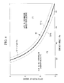
- Fig. 6 illustrates a relationship between the contact angle ⁇ e formed between the smooth surface of the material and the waterdrop, and the depth 12D/width 12W of the groove 12.
- the contact angle ⁇ e is formed between the smooth surface on which the groove 12 is not formed and the waterdrop, and is constant without depending on the size of the waterdrop, or posture of the material disposed.
- a basic criteria zone B1 including the basic criteria Cr1 and near values of its upper and lower sides is set.
- the depth 12D/width 12W of the groove 12 is determined such that it becomes larger than the basic criteria zone B1.
- the upper side means an area where the value of the depth 12D/width 12W of the groove 12 is larger than the basic criteria Cr1.
- the lower side means an area where the value of the depth 12D/width 12W of the groove 12 is smaller than the basic criteria Cr1.
- the basic criteria zone B1 is within a range of basic criteria Cr1 1 where the contact angle ⁇ e is smaller than a measured value by 10% (in the case of 0.9 ⁇ e) to basic criteria Cr1 2 where the contact angle ⁇ e is larger than the measured value by 10% (in the case of 1.1 ⁇ e). Even if the contact angle ⁇ e includes a measurement error, the surface small structure 10A becomes water repellent in the area F1 where the depth 12D/width 12W of the groove 12 is larger than the basic criteria zone B1.
- the surface small structure 10A becomes hydrophilic.
- the surface small structure 10A can be water repellent because a bridge phenomenon to be described later occurs, so that the depth 12D/width 12W of the groove 12 may be set within the range.
- the measured value of the contact angle ⁇ e is about 45° to 90° in the case where the material is aluminum.
- the contact angle ⁇ e is about 50° to 70°.
- the contact angle ⁇ e is about 80° to 90°.
- the inventor focused on entanglement of air between the material and the waterdrop as one of factors influencing the contact angle ⁇ e.
- sensitivity evaluation of shape factors to the contact angle ⁇ e was performed using Taguchi methods (quality engineering).
- the shape factors used for the evaluation are the width 12W, the depth 12D, and the pitch 12P of the groove 12, cross section shapes of the groove 12 (rectangle, U-shape (including an arc shape), V-shape), and patterns formed by the plurality of grooves 12 (latticed pattern, striped pattern, spotted pattern).
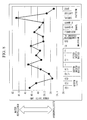
- Results illustrated in Fig.8 were obtained by the sensitivity evaluation.
- a vertical axis in Fig. 8 indicates an influence degree (sensitivity) of each factors on the contact angle ⁇ e, the water repellency becomes higher as the vertical axis approaches to the upper side of Fig. 8 , and the hydrophilicity becomes higher as the vertical axis approaches to the lower side of Fig. 8 .
- the sensitivity of the width 12W, and the depth 12D of the groove 12, and the pattern to the contact angle ⁇ e are larger than that of the other factors.
- the water repellency becomes higher.
- the width 12W of the groove 12 becomes wider, or as the depth 12D of the groove 12 becomes shallower, the hydrophilicity becomes higher.
- Condition 1 the uneven structure of the surface small structure 10A (width 12W, the depth 12D, the pitch 12P of the groove 12 and the like) is sufficiently smaller than the diameter of the waterdrop.
- Condition 3 the waterdrop behaves such that a surface area thereof becomes smaller (minimization of surface energy).
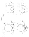
- the waterdrop 14 is spherical before coming in contact with the surface small structure 10A ( Fig. 9(a) ), and then part of the spherical surface of the waterdrop 14 comes in contact with the surface 11 of the surface small structure 10A ( Fig. 9(b) ).
- the waterdrop 14 also comes in contact with next surfaces 11B and 11C while extending over both side grooves 12, 12 from the contact portion (surface 11A) ( Fig. 9(c) ). While repeating the behaviors the number of times depending on a volume of the waterdrop 14, the waterdrop 14 spreads to be stable ( Fig. 9(d) ). A contact angle ⁇ actually formed between the surface small structure 10A and the waterdrop 14 is measured in the state of Fig. 9(d) .
- the waterdrop 14 comes in contact with the surface 11A of the surface small structure 10A. Since the uneven structure of the surface small structure 10A is sufficiently smaller than the diameter of the waterdrop 14 (condition 1), the waterdrop 14 comes in contact with the surface 11A, which is a top surface of a projection portion between the grooves 12, 12, and spreads to one edge 121 of an opening of the groove 12.
- the waterdrop 14 tends to enter toward a deeper position of the groove 12, but does not reach a bottom 124 of the groove 12 and reaches the other edge 122 (opposite side) of the groove 12.
- a cross section shape of the waterdrop 14 inside the groove 12 at the time of reaching the opposite surface 11B after the waterdrop 14 extending over the groove 12 can be approximated by a straight line as illustrated in Fig. 10(c) from the condition 3.
- the waterdrop 14 partitions the groove 12 into the inner side and the outer side, and thus the air 15 is entangled between the waterdrop 14 and the material.
- the waterdrop 14 further spreads on the surface 11B as illustrated in Fig. 10(d) .
- the waterdrop 14 behaves such that the surface area thereof becomes smaller (condition 3)
- the waterdrop 14 does not swell downward inside the groove 12 and keeps a straight line shape.
- the waterdrop 14 repeats the behaviors in Figs. 10(a) to (d) to be stable (see Fig. 9(d) ).
- Figs. 10(a) to (d) only the right side of the waterdrop 14 is illustrated, but the left side of the waterdrop 14 also spreads like the right side. Further, the waterdrop 14 also spreads in the length direction of the groove 12 (direction orthogonal to the paper surface) to be stable in a state that its own weight and surface tension are balanced.
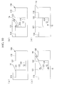
- the waterdrop 14 comes in contact with the surface 11A of the surface small structure 10A. Since the uneven structure of the surface small structure 10A is sufficiently smaller than the diameter of the waterdrop 14 (condition 1), the waterdrop 14 comes in contact with the surface 11A, which is the top surface of the projection portion between the grooves 12, 12, and spreads to one edge 121 of the opening of the groove 12.
- the waterdrop 14 flows out from the other edge 122 (opposite side) of the groove 12 into the surface 11B. That is, when the groove 12 is shallow, the air 15 is not entangled between the waterdrop 14 and the material. Thereafter, the waterdrop 14 repeats the behaviors in Figs. 11(a) to (d) to be stable.
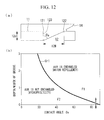
- a diagram of a model of the groove 12 configuring the surface small structure 10A was drawn ( Fig. 12(a) ). Based on this model, a geometric relationship of the width 12W and the depth 12D of the groove 12 is obtained.
- the cross section of the groove 12 can be illustrated by a two-dimensional shape and the shape of the waterdrop entered into the inside of the groove 12 can be illustrated by a straight line for simplicity.
- a value of the depth 12D can be expressed as A/tan ⁇ e.
- the value of the depth 12D/width 12W of the groove 12 is 1/tan ⁇ e.
- this 1/tan ⁇ e basic criteria Cr1
- the basic criteria Cr1 depth 12D/width 12W
- the basic criteria Cr1 is also determined depending on the contact angle ⁇ e.
- the smooth surface of the aluminum alloy material of the fin 10 has the contact angle ⁇ e of about 84°, if the ratio of the depth 12D to the width 12W of the groove 12 exceeds 0.1, which is the basic criteria Cr1, the water repellency becomes higher (see an upward arrow), and if the ratio is less than 0.1, the hydrophilicity becomes higher (see a downward arrow).
- the value of the depth 12D/width 12W of the groove 12 is set larger than 0.1.
- the water repellency becomes higher with distance from the basic criteria Cr1 within the area F1 where the value of the depth 12D/width 12W of the groove 12 is larger than the basic criteria Cr1, and thus the necessary water repellency can be obtained by adjusting the size of the depth 12D/width 12W of the groove 12.
- the basic criteria Cr1 as described above is set to the groove 12 having the inner wall 123 perpendicular to the surface 11 and the rectangular cross section shape ( Fig. 12(a) ).
- Fig. 13(a) illustrates a case where the inclination angle ⁇ w is small
- Fig. 13(b) illustrates a case where the inclination angle ⁇ w is large.
- the inclination criteria Cr2 (depth/width) is expressed by the following equation (3).
- Cr ⁇ 2 cos ⁇ e - ⁇ w / tan ⁇ w • cos ⁇ e - ⁇ w + sin ⁇ e - ⁇ w
- Fig. 14 illustrates the inclination criteria Cr2 in the case where the contact angle ⁇ e is 84° (aluminum material).
- the contact angle ⁇ e is 84° (aluminum material).
- the depth 12D of the groove 12 required to form the bridge increases.
- the inclination angle ⁇ w increases to the predetermined angle or more (herein, about 45° or more), the bridge phenomenon does not occur.
- an inclination criteria zone B2 including the inclination criteria Cr2 and near values of its upper and lower sides is set.
- the inclination criteria zone B2 is within a range of inclination criteria Cr2 1 where the inclination angle ⁇ w is smaller by 10% than the measured value to inclination criteria Cr2 2 where the inclination angle ⁇ w is larger by 10% than the measured value.
- the upper side means an area where the value of the depth 12D/width 12W of the groove 12 is larger than the inclination criteria Cr2.
- the lower side means an area where the value of the depth 12D/width 12W of the groove 12 is smaller than the inclination criteria Cr2.
- the water repellency can certainly be obtained in an area where the value of the depth 12D/width 12W of the groove 12 is larger than the inclination criteria zone B2.
- the water repellency can be obtained because the bridge phenomenon occurs, so that the depth/width of the groove 12 may be set within the range.
- a hydrophilicity area F B separated from water repellency area F A by the inclination criteria Cr2 when the ratio of the depth 12D to the width 12W of the groove 12 is increased, the hydrophilicity is enhanced (right portion in Fig. 14 ). This is because the groove 12 is deep and thus a specific surface area is increased (increase of surface roughness).
- the cross section shape of the groove 12 of the surface small structure 10A is not limited to the rectangle ( Fig. 12(a) ) or trapezoid ( Fig. 13(a) ), but it may be the U-shape or V-shape.
- the depth 12D/width 12W of the groove 12 can be determined using the inclination criteria Cr2 by setting the inclination angle ⁇ w along the inner wall 123.
- the width 12W of the groove 12 can be set to about one fourth or less of the diameter of the waterdrop in order to form the bridge, and, for example, it can be set to 5 ⁇ m or more to 200 ⁇ m or less. It is preferably 30 ⁇ m or more to 100 ⁇ m or less. A condition that the width 12W is set to 5 ⁇ m or more to 200 ⁇ m or less is prescribed in the above described equation (1).
- the pitch between the grooves 12 can be set to any value larger than 0.
- the pitch 12P between the grooves 12 distance in the arrangement direction orthogonal to the extending direction of the groove 12
- a condition that the pitch 12P between the grooves 12 is set to 5 ⁇ m or more to twice or less the width 12W of the groove 12 is prescribed in the above described equation (2).
- the plurality of grooves 12 is formed at the fixed intervals in the arrangement direction orthogonal to the extending direction of the groove 12 (direction inclined from the axis x direction), but it is not necessarily be formed at the fixed intervals. Further, the pitches 12P between the grooves 12 are described as constant, but they are not necessarily be constant.
- the intervals of the grooves 12 in the arrangement direction are any intervals which are not constant, and the pitches 12P between the grooves 12 have any lengths which are not constant, the condition of the above described equation (2) is satisfied.
- the intervals of the grooves 12 in the arrangement direction may be any intervals which are not constant, and the pitches 12P between the grooves 12 may have any lengths which are not constant.
- a curved (shape extending linearly while meandering like waves) pattern can be adopted in addition to the straight line pattern.
- the latticed pattern can be adopted.
- the waterdrop moves diagonally at a portion where a straight line intersects with a straight line from one straight line to the other straight line. Therefore, in the portion where the straight lines intersect with each other, the width of the groove 12 becomes relatively larger than the depth of the groove 12 (diagonal intersecting with the vertical line and the horizontal line).
- the widths of the grooves 12 are made to be constant on the whole pattern, so that the intersecting portion where the width of the groove 12 becomes relatively larger than the other portions does not exist. Therefore, it is assumed that the bridge is easily formed on the whole pattern and thus the effect of the water repellency is excellent in the straight line or curved grooves 12 as compared with the latticed grooves 12.
- Fig. 14 Each indicate data of the sample manufactured at the time of the sensitivity evaluation of the shape factors described with reference to Fig. 7 .
- Each of the samples has the striped pattern grooves 12 formed by cutting.
- the samples corresponding to the plots 1 to 3 (P1 to P3) each have the inclination angle ⁇ w of 0°.
- the sample corresponding to the plot 4 (P4) has the inclination angle ⁇ w of 26°.
- the width of the groove 12 is 200 ⁇ m, the depth of the groove 12 is 200 ⁇ m, and the depth/width is 1.
- the pitch between the grooves 12 is 200 ⁇ m.
- the width of the groove 12 is 100 ⁇ m, the depth of the groove 12 is 10 ⁇ m, and the depth/width is 0.1.
- the pitch between the grooves 12 is 50 ⁇ m.
- the width of the groove 12 is 100 ⁇ m, the depth of the groove 12 is 25 ⁇ m, and the depth/width is 0.25.
- the pitch between the grooves 12 is 200 ⁇ m.
- the width of the groove 12 is 100 ⁇ m, the depth of the groove 12 is 100 ⁇ m, and the depth/width is 1.
- the pitch between the grooves 12 is 100 ⁇ m.
- each of the plots P1 to P4 belongs to the area of the inclination criteria Cr2 or more.
- the contact angle of the sample corresponding to the plot 1 is 147°.
- the contact angle of the sample corresponding to the plot 2 is 128°.
- the contact angle of the sample corresponding to the plot 3 is 116°.
- the contact angle of the sample corresponding to the plot 4 is 123°. From the above plot data, when the ratio of the depth/width of the groove 12 is determined to be the inclination criteria Cr2 or more, the wettability decreases and the water repellency is expressed.
- the outdoor heat exchanging apparatus 32 of this embodiment is formed with the plurality of grooves 12 formed at intervals in the arrangement direction orthogonal to the extending direction of the groove 12 on the surface of each of the plurality of plate shape fins 10.
- the width 12W of each of the plurality of grooves 12 is preferably set to 5 ⁇ m or more to 200 ⁇ m or less.
- the width 12W of the groove is sufficiently narrower than the size of the waterdrop. Therefore, the phenomenon (bridge phenomenon) occurs, the bridge phenomenon being the phenomenon in which the waterdrop formed on the upper part of the groove 12 does not reach the bottom 124 of the groove and is disposed to extend over the groove 12 from one edge to the other edge.
- the water repellency of the fin 10 becomes higher because the bridge phenomenon occurs.
- the ratio of the depth 12D of the groove 12 to the width 12W of the groove 12 is set to 1/tan ⁇ or more when the contact angle formed between the surface of the fin 10 and the waterdrop is ⁇ e.
- ⁇ 1.1 ⁇ e
- 1/tan ⁇ is the basic criteria Cr1 1 , which is the lower limit of the basic criteria zone B1.
- the ratio of the depth 12D of the groove 12 to the width 12W of the groove 12 to the basic criteria Cr1 or more, the basic criteria Cr1 being larger than the basic criteria Cr1 1 which is the lower limit of the basic criteria zone B1, that is by setting the ratio to 1/tan ⁇ e or more, the more sufficient water repellency can be given to the surface of the fin 10.
- the outdoor unit 30 of this embodiment includes the outdoor heat exchanging apparatus 32, and the propeller fan 33 introducing the air toward the outdoor heat exchanging apparatus 32. It is preferable that the plurality of grooves 12 each extend along the direction inclined from the vertical direction from the upper part to the lower part and extend in the direction descending from the upstream side to the downstream side of the flowing direction of the air introduced with the propeller fan 33.
- the waterdrop formed on the surface of the fin 10 to which the water repellency is given can be dripped by its own weight along the groove 12 formed from the upper part to the lower part in the direction inclined from the vertical direction. Further, the waterdrop formed on the surface of the fin 10 can be dripped along the groove 12 by the air introduced with the propeller fan 33.
- the waterdrop formed on the surface of the fin 10 can be certainly dripped by action of its own weight and the air introduced with the propeller fan 33.
- the second embodiment is a modified example of the first embodiment, and the second embodiment is the same as the first embodiment unless description is specifically given hereinafter, and thus description thereof is omitted.
- the outdoor heat exchanging apparatus 32 of the first embodiment is the fin and tube type heat exchanging apparatus including the heat transfer tube 40A having a circular cross section.
- an outdoor heat exchanging apparatus 32' of the second embodiment is a fin and tube type heat exchanging apparatus including a heat transfer tube 40'A having a flat cross section.
- the outdoor heat exchanging apparatus 32' of this embodiment includes a plurality of heat transfer tubes 40'A and a header 40'B connected to the plurality of heat transfer tubes 40'A.
- tube holes 10'B provided on a fin 10' of this embodiment each has a shape in which an upstream side in an air flowing direction indicated by an arrow opens.
- the heat transfer tube 40'A of this embodiment has the flat cross section, and is formed with a plurality of refrigerant passages thereinside.
- the outdoor heat exchanging apparatus 32' of this embodiment is the flat heat transfer tube 40'A, the fin 10' and the heat transfer tubes 40'A are typically joined by furnace brazing.
- the outdoor heat exchanging apparatus 32' in an assembled state by the furnace brazing has to be soaked in the coating liquid.
- the outdoor heat exchanging apparatus 32' in the assembled state is large, and thus large equipment is necessary for soaking it in the coating liquid, which increases workload.
- the outdoor heat exchanging apparatus 32' of this embodiment makes the fin 10' have the water repellency by forming grooves 12' to be described later on the surface of the fin 10', the above described problem of the soaking in the coating liquid does not occur.
- arrows in Figs. 17(a) and (b) each indicate a flowing direction of the air introduced with the propeller fan 33.
- reference numeral 12' is given to the only two grooves, and is not given to the other grooves 12' to omit the description thereof.
- the surface of the fin 10' is formed with the plurality of grooves 12' each extending from an upper part to a lower part along an axis X extending in a vertical direction.
- the plurality of grooves 12' is formed at fixed intervals in an arrangement direction orthogonal to the extending direction of the groove 12' (axis x direction).
- Fig. 17(b) illustrates a modified example of the fin 10'.
- the surface of the fin 10' in the modified example is formed with the grooves 12' each extending from an upper part to a lower part along a direction inclined from the vertical direction.
- the plurality of grooves 12' is formed at fixed intervals in an arrangement direction orthogonal to the extending direction of the groove 12' (direction inclined from the axis x direction).
- an angle formed between an axis Y2 indicating the extending direction of the groove 12' and the axis x along the vertical direction is an angle Z2 in a plane where the surface of the fin 10' is disposed.
- the reason why the axis Y2 is inclined from the axis X by the angle Z2 in this manner is to utilize power of the air introduced with the propeller fan 33 for making the waterdrops formed on the surface of the fin 10' drip toward the lower part of the fin 10'.
- the groove 12' extends in a direction descending from an upstream side to a downstream side of the air flowing direction indicated by the arrow. Therefore, the waterdrop formed on the surface of the fin 10' can be dripped along the groove 12' by the air introduced with the propeller fan 33.
- the angle Z2 described above is set to any value larger than 0° and smaller than 90° depending on various conditions, such as the number of rotations, or air volume of the propeller fan 33. From the same reason as the first embodiment, it is desirable that the angle Z2 is set to about 40° (for example, 20° or more to 60°or less).
- the outdoor heat exchanging apparatus 32' which is the fin and tube type heat exchanging apparatus including the flat heat transfer tube 40'A, it is possible to give the water repellency to the fin 10' by forming the plurality of grooves 12' on the fin 10'.
- the fin 10' and the heat transfer tubes 40'A are typically joined by furnace brazing. Therefore, in order to make the fin 10' have the water repellency by soaking it in the coating liquid, the large equipment is necessary for soaking it in the coating liquid, which increases workload.
- the fin 10' has the water repellency without being soaked in the coating liquid, and thus the problem of the soaking in the coating liquid can be suppressed.
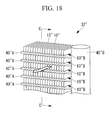
- the third embodiment is a modified example of the second embodiment, and the third embodiment is the same as the first embodiment and the second embodiment unless description is specifically given hereinafter, and thus description thereof is omitted.
- the outdoor heat exchanging apparatus 32' which is the fin and tube type heat exchanging apparatus including the flat heat transfer tube 40'A, adopts the tube hole 10'B having the shape in which the upstream side in the air flowing direction opens.
- an outdoor heat exchanging apparatus 32" which is a fin and tube type heat exchanging apparatus including a flat heat transfer tube 40" A, adopts a tube hole 10" B having a shape in which a downstream side in an air flowing direction opens.
- the outdoor heat exchanging apparatus 32" of this embodiment includes the plurality of heat transfer tubes 40" A and a header 40" B connected to the plurality of heat transfer tubes 40" A.
- tube holes 10" B provided on a fin 10" of this embodiment each has the shape in which the downstream side in the air flowing direction indicated by an arrow opens.
- the heat transfer tube 40" A of this embodiment has the flat cross section, and is formed with a plurality of refrigerant passages thereinside.
- the outdoor heat exchanging apparatus 32" of this embodiment has the water repellency by forming grooves 12" to be described later on the surface of the fin 10", it is advantageous that the above described problem of the soaking in the coating liquid does not occur.
- arrows in Figs. 19(a) and (b) each indicate a flowing direction of the air introduced with the propeller fan 33.
- reference numeral 12" is given to the only two grooves, and is not given to the other grooves 12" to omit the description thereof.
- the surface of the fin 10" is formed with the plurality of grooves 12" each extending from an upper part to a lower part along an axis X extending in a vertical direction.
- the plurality of grooves 12" is formed at fixed intervals in an arrangement direction orthogonal to the extending direction of the groove 12" (axis x direction).
- Fig. 19(b) illustrates a modified example of the fin 10''.
- the surface of the fin 10 in the modified example is formed with the grooves 12" each extending from an upper part to a lower part along a direction inclined from the vertical direction.
- the plurality of grooves 12" is formed at fixed intervals in an arrangement direction orthogonal to the extending direction of the groove 12" (direction inclined from the axis x direction).
- an angle formed between an axis Y3 indicating the extending direction of the groove 12" and the axis x along the vertical direction is an angle Z3 in a plane where the surface of the fin 10" is disposed.
- the reason why the axis Y3 is inclined from the axis X by the angle Z3 in this manner is to utilize power of the air introduced with the propeller fan 33 for making the waterdrops formed on the surface of the fin 10" drip toward the lower part of the fin 10".
- the groove 12" extends in a direction descending from an upstream side to a downstream side of the air flowing direction indicated by the arrow. Therefore, the waterdrops formed on the surface of the fin 10" can be dripped along the groove 12" by the air introduced with the propeller fan 33.
- the angle Z3 described above may be set to any value larger than 0° and smaller than 90° depending on various conditions, such as the number of rotations, or air volume of the propeller fan 33. From the same reason as the first embodiment, it is desirable that the angle Z3 is set to about 40° (for example, 20° or more to 60°or less).
- the outdoor heat exchanging apparatus 32" which is the fin and tube type heat exchanging apparatus including the flat heat transfer tube 40" A, it is possible to give the water repellency to the fin 10" by forming the plurality of grooves 12" on the fin 10.
- the fin 10" and the heat transfer tubes 40" A are typically joined by furnace brazing. Therefore, in order to make the fin 10" have the water repellency by soaking it in the coating liquid, the large equipment is necessary for soaking it in the coating liquid, which increases workload.
- the fin 10" has the water repellency without being soaked in the coating liquid, and thus the problem of the soaking in the coating liquid can be suppressed.
- the surface small structure 10A (10'A, 10" A) may be provided on only one surface of the fin 10 (fin 10', fin 10").
- the shape of the fin 10 (fin 10', fin 10") is not limited to the shapes described in the above embodiments, and may be a corrugated shape.
- the surface small structure 10A (10'A, 10" A) may be provided on the surface of the heat transfer tube 40A (40'A, 40" A) which may come in contact with water, or ice.
Landscapes
- Engineering & Computer Science (AREA)
- Physics & Mathematics (AREA)
- Thermal Sciences (AREA)
- Mechanical Engineering (AREA)
- General Engineering & Computer Science (AREA)
- Geometry (AREA)
- Chemical & Material Sciences (AREA)
- Crystallography & Structural Chemistry (AREA)
- Heat-Exchange Devices With Radiators And Conduit Assemblies (AREA)
Abstract
Description
- The present invention relates to a heat exchanging apparatus and an air conditioning apparatus.
- A heat exchanging apparatus configuring an air conditioning apparatus includes a tube inside which a refrigerant flows and a fin thermally coupled to the tube, and performs heat exchange between the refrigerant inside the tube and air passing through between the fins. A coating is performed on a surface of the fin for giving hydrophilicity or water repellency to the fin, in order to prevent decrease of efficiency with increase of ventilation resistance between the fins due to dew condensation and frost formation on the fin of the heat exchanging apparatus, or to prevent water splashes from the fin to an air conditioner space. The fin is typically made of aluminum, and a surface of an aluminum material shows slight hydrophilicity, but it is desirable that the fin has higher hydrophilicity or sufficient water repellency.
- When the surface of the fin has sufficient hydrophilicity, water spreads along the surface of the fin. Thus, ventilation resistance between the fins can be suppressed even when dew condensation and frost formation occur. Further, the surface of the fin retains water because of the sufficient hydrophilicity, thereby suppressing water splashes. On the other hand, when the surface of the fin has sufficient water repellency, moisture is difficult to attach to the surface of the fin. Thus, water or frost does not form a large lump, thereby suppressing the ventilation resistance between the fins.
- Therefore, there have been performed on a surface of a material a water repellency coating using a water repellency material typified by a fluorine-based resin, or a hydrophilicity coating using a hydrophilicity material such as a silicone-based resin, in order to obtain necessary water repellency or hydrophilicity. Further, water repellency or hydrophilicity depends on chemical properties and surface roughness of a material. It has been known that as surface roughness increases by forming small unevenness on the surface, the surface of the material shows higher hydrophilicity or water repellency (Wenzel's equation).
- In
Patent Literature 1, an uneven structure is formed on a surface of an aluminum member (fin) by soaking the fin in acid, and then a water repellency coating is performed thereon using a fluorine-based resin material, so that the fin has higher water repellency than that of the fin on which the water repellency coating is only performed. - {PTL 1}
Japanese Unexamined Patent Application, Publication No.2010-174269 - A coating of a fin of a heat exchanging apparatus is performed by soaking in a coating liquid a sheet material forming the fin, or an assembly in which the fin and a tube are fit together. Therefore, in order to perform the coating, a liquid tank fit for a size of the fin for storing the coating liquid and the coating liquid that fills the liquid tank are necessary, which increases cost corresponding to the coating liquid and the liquid tank.
- Further, in addition to forming the fin and fitting the fin and the tube together, the coating step is necessary. Before the coating, acid cleaning, water washing, a conversion coating of a base and the like are necessary, and after the coating, burning is performed, which increase steps and also take time. In particular, when the coating is performed on a fin of a heat exchanger disposed outdoors, it is difficult to secure durability of the coating which can withstand long-term use.
- The present invention has been made in view of the above problems, and an object thereof is to provide a heat exchanging apparatus that suppresses the problem of increasing ventilation resistance due to dew condensation and frost formation on the fin by giving the sufficient water repellency to the surface of the fin without performing the coating, and an air conditioning apparatus including the heat exchanging apparatus.
- In order to achieve the above object, the present invention adopts the following solutions.
- A heat exchanging apparatus according to the present invention includes: a plurality of fins each having a plate shape and extending in a vertical direction, the plurality of fins being arranged successively in a horizontal direction in a state that surfaces of the adjacent pair of fins are parallel to each other; and a heat transfer tube inside which a refrigerant flows, the heat transfer tube being inserted into a tube hole provided on each of the plurality of fins while adhering. In the heat exchanging apparatus, a plurality of grooves each extending from a upper part to a lower part is formed on the surface of each of the fins at intervals in an arrangement direction orthogonal to the extending direction of each of the grooves, and a width of each of the grooves is 5 µm or more to 200 µm or less and a distance between edges of the adjacent grooves in the arrangement direction is 5 µm or more to twice or less the width of each of the grooves.
- In the heat exchanging apparatus according to the present invention, the width of each of the grooves formed on the surface of each of the plate shape fins at intervals in the arrangement direction is 5 µm or more to 200 µm or less. When a size of a waterdrop formed on the surface of the fin is 1 mm or more to 3 mm or less, the width of the groove is sufficiently narrower than the size of the waterdrop. Therefore, a phenomenon (bridge phenomenon) occurs, the bridge phenomenon being the phenomenon in which the waterdrop formed on an upper part of the groove does not reach a bottom of the groove and is disposed to extend over the groove from one edge to the other edge. The water repellency of the surface of the fin becomes higher because the bridge phenomenon occurs.
- In the heat exchanging apparatus according to the present invention, the distance between the edges of the adjacent grooves is 5 µm or more to twice or less the width of each of the grooves. When the size of the waterdrop formed on the surface of the fin is 1 mm or more to 3 mm or less in diameter, the distance between the edges of the grooves is sufficiently smaller than the size of the waterdrop. Therefore, the surface of the fin between the edges of the grooves shows the sufficient water repellency.
- In this manner, the present invention can provide the heat exchanging apparatus that suppresses a problem of increasing ventilation resistance due to dew condensation and frost formation on the fin by giving the sufficient water repellency to the surface of the fin without performing a coating.
- In the heat exchanging apparatus of a first aspect of the present invention, when a contact angle formed between the surface of each of the fins and the waterdrop is θe, a ratio of a depth of each of the grooves to the width of each of the grooves is 1/tan α or more, where α = 1.1θe.
- In the case where the waterdrop reaches the bottom of the groove on one edge side of the groove and at the same time the phenomenon (bridge phenomenon) in which the waterdrop is disposed to extend over the groove to the other edge occurs, assuming that the width of the groove is W1 and the depth of the groove is D1, a relationship of D1/W1 = 1/tan θe is established. Further, as the width of the groove becomes narrower and the depth of the groove becomes deeper, the water repellency becomes higher, and as the width of the groove becomes wider and as the depth of the groove becomes shallower, the hydrophilicity becomes higher.
- When the ratio of the depth of the groove to the width of the groove corresponds to 1/tan θe, the water repellency is sufficiently shown. Thus, even when the ratio of the depth of the groove to the width of the groove is lower than 1/tan θe, if it is near 1/tan θe, the water repellency is sufficiently shown. Accordingly, by setting the ratio of the depth of the groove to the width of the groove to 1/tan α (α = 1.1θe) or more, which is smaller than 1/tan θe, the sufficient water repellency can be given to the surface of the fin.
- In the heat exchanging apparatus of a second aspect of the present invention, a ratio of a depth of each of the grooves to the width of each of the grooves is 1/tan θe or more.
- By setting the ratio of the depth of the groove to the width of the groove to 1/tan θe or more, in which the water repellency is sufficiently shown, the sufficient water repellency can be given to the surface of the fin.
- In the heat exchanging apparatus of a third aspect of the present invention, a ratio of a depth of each of the grooves to the width of each of the grooves is 1/tan β or more, where β = 0.9θe.
- By setting the ratio of the depth of the groove to the width of the groove to 1/tan β (β = 0.9θe) or more, which is larger than 1/tan θe, in which the water repellency is sufficiently shown, the sufficient water repellency can certainly be given to the surface of the fin.
- In the heat exchanging apparatus of the first aspect to the third aspect described above, a cross section shape of each of the grooves may be rectangular in a plane orthogonal to the extending direction.
- Thereby, the sufficient water repellency can be given to the surface of the fin on which the plurality of grooves each having the rectangular cross section is formed.
- In the heat exchanging apparatus of a fourth aspect of the present invention, each of the plurality of grooves extends from the upper part to the lower part along a vertical direction.
- Thereby, the waterdrop formed on the surface of the fin to which the water repellency is given, can certainly be dripped toward the lower part of the fin by its own weight along the groove formed from the upper part to the lower part in the vertical direction.
- In the heat exchanging apparatus of a fifth aspect of the present invention, each of the plurality of grooves extends from the upper part to the lower part along a direction inclined from a vertical direction.
- Thereby, the waterdrop formed on the surface of the fin to which the water repellency is given, can certainly be dripped toward the lower part of the fin by its own weight along the groove formed from the upper part to the lower part in the direction inclined from the vertical direction.
- An air conditioning apparatus of the present invention includes the heat exchanging apparatus according to any one of the first to fifth aspects; and a fan introducing air toward the heat exchanging apparatus.
- Thereby, it is possible to provide the air conditioning apparatus that suppresses a problem of increasing ventilation resistance due to dew condensation and frost formation on the fin by giving the sufficient water repellency to the surface of the fin without performing a coating.
- In the air conditioning apparatus of another aspect of the present invention, each of the plurality of grooves extends from the upper part to the lower part along a direction inclined from a vertical direction, and extends in a direction descending from an upstream side to a downstream side of a flowing direction of the air introduced with the fan.
- Thereby, the waterdrop formed on the surface of the fin to which the water repellency is given, can be dripped by its own weight along the groove formed from the upper part to the lower part in the direction inclined from the vertical direction. Further, the waterdrop formed on the surface of the fin can be dripped along the groove by the air introduced with the fan.
- Accordingly, in this aspect, the waterdrop formed on the surface of the fin can be certainly dripped by action of its own weight and the air introduced with the fan.
- The present invention can provide a heat exchanging apparatus that suppresses a problem of increasing ventilation resistance due to dew condensation and frost formation on a fin by giving sufficient water repellency to a surface of the fin without performing a coating.
-
- {
Fig. 1 }
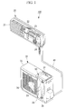
Fig. 1 is a perspective view illustrating an air conditioning apparatus of a first embodiment. - {
Fig. 2 }
Fig. 2 is a perspective view illustrating an outdoor unit of the first embodiment. - {
Fig. 3 }
Fig. 3 is a perspective view illustrating a heat exchanging apparatus illustrated inFig. 2 . - {
Figs. 4(a) and (b) }
Figs. 4(a) and (b) each are an arrow view along A-A line of fins illustrated inFig. 3 .Fig. 4(a) illustrates the fin on which grooves each extending along a vertical direction are formed, andFig. 4(b) illustrates the fin on which grooves each extending along a direction inclined from the vertical direction are formed. - {
Fig. 5 }
Fig. 5 is perspective view schematically illustrating the enlarged fin illustrated inFig. 3 . - {
Fig. 6 }
Fig. 6 is a diagram illustrating basic criteria prescribing a threshold between water repellency and hydrophilicity in a depth/width of the groove in a surface small structure formed on the fin. - {
Fig. 7 }
Fig. 7 is a diagram illustrating shape factors used for evaluating sensitivity to a contact angle. - {
Fig. 8 }
Fig. 8 is a diagram illustrating results of the sensitivity evaluation. - {
Figs. 9(a) to (d) }
Figs. 9(a) to (d) are views illustrating a state that a waterdrop comes in contact with the surface small structure to spread. - {
Figs. 10(a) to (d) }
Figs. 10(a) to (d) are views for illustrating that air is entangled when the groove is deep. - {
Figs. 11(a) to (d) }
Figs. 11(a) to (d) are views for illustrating that air is not entangled when the groove is shallow. - {
Figs. 12(a) and (b) }
Fig. 12(a) is a view illustrating a model of the groove in the surface small structure used for settling on the basic criteria, andFig. 12(b) is a diagram identical toFig. 6 . - {
Figs. 13(a) and (b) }
Figs. 13(a) and (b) each are a view for illustrating a case that inner walls of the groove are inclined toward a surface of the groove. - {
Fig. 14 }
Fig. 14 is a diagram illustrating inclination criteria prescribing a threshold between water repellency and hydrophilicity when the inner walls of the groove are inclined as illustrated inFigs. 13(a) and (b) . - {
Figs. 15(a) to (b) }
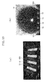
Fig. 15(a) is a digital microscope photograph of the surface small structure, andFig. 15(b) is a photograph illustrating a state that air is entangled to be water repellent in the surface small structure. - {
Fig. 16 }
Fig. 16 is a perspective view illustrating a heat exchanging apparatus of a second embodiment. - {
Figs. 17 (a) and (b) }
Figs. 17(a) and (b) each are an arrow view along B-B line of fins illustrated inFig. 16 .Fig. 17(a) illustrates the fin on which grooves each extending along a vertical direction are formed, andFig. 17(b) illustrates the fin on which grooves each extending along a direction inclined from the vertical direction are formed. - {
Fig. 18 }
Fig. 18 is a perspective view illustrating a heat exchanging apparatus of a third embodiment. - {
Figs. 19 (a) and (b) }
Figs. 19(a) and (b) each are an arrow view along C-C line of fins illustrated inFig. 18 .Fig. 19(a) illustrates the fin on which grooves each extending along a vertical direction are formed, andFig. 19(b) illustrates the fin on which grooves each extending along a direction inclined from the vertical direction are formed. - With reference to the drawings, hereinafter, description will be given of an
air conditioning apparatus 100 of a first embodiment of the present invention. - As illustrated in
Fig. 1 , theair conditioning apparatus 100 of the first embodiment includes anindoor unit 20 and anoutdoor unit 30. In theindoor unit 20 and theoutdoor unit 30, a refrigerant flows from theindoor unit 20 into theoutdoor unit 30, or from theoutdoor unit 30 into theindoor unit 20 through a pair ofrefrigerant piping 40. Further, theindoor unit 20 and theoutdoor unit 30 are electrically connected to each other with electrical wiring (not illustrated). - The
indoor unit 20 includes a rear surface base (not illustrated) and afront surface panel 21 which are integrally configured. An indoorheat exchanging apparatus 22 of a plate fin tube type, anindoor fan 23 having a substantially cylindrical shape, and acontrol part 24 controlling operation of theindoor unit 20 are fitted to the base. - As illustrated in
Figs. 1 and2 , theoutdoor unit 30 includes acasing 31. An outdoor heat exchanging apparatus 32 (heat exchanging apparatus), a propeller fan 33 (fan), acompressor 34, and an outdoor unitelectrical equipment box 50 are provided inside thecasing 31. Theoutdoor unit 30 is provided with abaffle plate 35 on a substantially center position, thebaffle plate 35 separating the inside of theoutdoor unit 30 into two spaces. - The
propeller fan 33 is disposed on the left space and thecompressor 34 is disposed on the right space when theoutdoor unit 30 is viewed from the front. Thepropeller fan 33 rotates counterclockwise when theoutdoor unit 30 is viewed from the front, and generates airflow inside thecasing 31 in a direction from the rear surface to the front surface (direction indicated by an arrow inFig. 2 ). Thepropeller fan 33 is a device that introduces outside air (air) toward the outdoorheat exchanging apparatus 32 in this manner. - A fin guard (not illustrated) and a
fan guard 36 are provided on the rear surface of thecasing 31 from which the outdoorheat exchanging apparatus 32 faces the outside, and on the front surface of thecasing 31 from which thepropeller fan 33 faces the outside, respectively. The fin guard is provided for preventing thefins 10 being damaged by unexpected impact from the outside. Similarly, thefan guard 36 is provided for protecting thepropeller fan 33 from impact from the outside and also preventing dust included in outside air from coming into the inside of thecasing 31. - The
compressor 34 changes a gas refrigerant having a low temperature and pressure into a gas refrigerant having a high temperature and pressure and then discharges it. Herein, a refrigerant circuit includes thecompressor 34, the indoorheat exchanging apparatus 22, the outdoorheat exchanging apparatus 32, therefrigerant piping 40, an expansion valve (not illustrated), a four-way valve controlling the flowing direction of the refrigerant (not illustrated) and the like. The refrigerant circuit is a circuit circulating the refrigerant between theindoor unit 20 and theoutdoor unit 30 through the pair ofrefrigerant piping 40. - Herein, description will be given of operation of the
air conditioning apparatus 100 in each case of heating operation and cooling operation. - During the heating operation, the gas refrigerant having the high temperature and pressure in the
compressor 34 is pressure-fed to the indoorheat exchanging apparatus 22 of theindoor unit 20 through therefrigerant piping 40 illustrated inFig. 1 . Inside theindoor unit 20, the refrigerant having the high temperature and pressure and flowing through the indoorheat exchanging apparatus 22 gives heat to indoor air taken with theindoor fan 23. By this heat exchange, hot air, that is air to which the heat is given, is blown from an air outlet 21c. The gas refrigerant having the high temperature and pressure is condensed to be liquefied by the heat exchange in the indoorheat exchanging apparatus 22, and becomes a liquid refrigerant having a high temperature and pressure. - The liquid refrigerant having the high temperature and pressure is decompressed with the expansion valve while being fed to the outdoor
heat exchanging apparatus 32 of theoutdoor unit 30, and has a low temperature and pressure. In theoutdoor unit 30, the liquid refrigerant having the low temperature and pressure and flowing through the outdoorheat exchanging apparatus 32 takes heat from air newly taken from the outside into the inside of thecasing 31 with thepropeller fan 33. By this heat exchange, the liquid refrigerant having the low temperature and pressure is evaporated to be gasified, and becomes a gas refrigerant having a low temperature and pressure. The gas refrigerant having the low temperature and pressure is fed to thecompressor 34 to have a high temperature and pressure. Theair conditioning apparatus 100 performs the heating operation by repeating the above steps. - Meanwhile, during the cooling operation, the refrigerant flows in the refrigerant circuit in a direction opposite to the direction during the heating operation. That is, the gas refrigerant having the high temperature and pressure in the
compressor 34 is pressure-fed to the outdoorheat exchanging apparatus 32 through therefrigerant piping 40. In the outdoorheat exchanging apparatus 32, outdoor air takes heat from the gas refrigerant, so that the gas refrigerant is condensed to be liquefied. Thereby, the gas refrigerant having the high temperature and pressure becomes a liquid refrigerant having a high temperature and pressure. The liquid refrigerant having the high temperature and pressure is decompressed with the expansion valve to have a low temperature and pressure, and is fed to the indoorheat exchanging apparatus 22 through therefrigerant piping 40 again. In the indoorheat exchanging apparatus 22, the liquid refrigerant having the low temperature and pressure takes heat from indoor air, and then cool air is blown from the air outlet 21c and the refrigerant itself is evaporated to be gasified. Thereby, the liquid refrigerant having the low temperature and pressure becomes a gas refrigerant having a low temperature and pressure. The gas refrigerant is fed to thecompressor 34 again to have a high temperature and pressure. Theair conditioning apparatus 100 performs the cooling operation by repeating the above steps. - Next, detailed description will be given of the outdoor
heat exchanging apparatus 32 of this embodiment. The outdoorheat exchanging apparatus 32 of this embodiment is a fin and tube type heat exchanging apparatus. - As illustrated in
Fig. 3 , the outdoorheat exchanging apparatus 32 is provided with a plurality offins 10 each having a plate shape extending along an axis X extending in a vertical direction. The plurality offins 10 is arranged successively in a horizontal direction in a state that surfaces of the adjacent pair offins 10 are parallel to each other. InFig. 3 ,reference numeral 10 is given to the only two fins, and is not given to the other fins to omit the description thereof. - When a line is drawn in a horizontal direction on the surface of the
fin 10, an extending direction of the line corresponds to an extending direction of a rotation axis of thepropeller fan 33. Therefore, air introduced with thepropeller fan 33 flows along a passage formed between the adjacent pair offins 10. The air introduced into the passage between the adjacent pair offins 10 flows out along an arrow direction illustrated inFig. 3 . - In this manner, the plurality of
fins 10 is arranged such that it does not disturb the flowing of the air introduced with thepropeller fan 33 and can transfer heat efficiently to the introduced air. - In the outdoor
heat exchanging apparatus 32 illustrated inFig. 3 , each of thefins 10 is provided withtube holes 10B, and aheat transfer tube 40A is inserted into each of the tube holes 10B. Theheat transfer tube 40A is a part of therefrigerant piping 40, and is a component through which the refrigerant flows in the outdoorheat exchanging apparatus 32. Theheat transfer tube 40A is inserted into thetube hole 10B while adhering, and the refrigerant (liquid) flows thereinside. - Heat of the refrigerant flowing inside the
heat transfer tube 40A is transferred to thefin 10 via theheat transfer tube 40A. Thefin 10 is made of a metallic material having high heat transfer ability. Therefore, thefin 10 can transfer the heat having transferred from the refrigerant to air around thefin 10 efficiently. - As the metallic material forming the
fin 10, for example, an aluminum material, an aluminum material on which a conversion coating is performed, or a stainless steel material can be used. - With reference to
Figs. 4(a) and (b) , hereinafter, description will be given ofgrooves 12 formed on the surface of thefin 10. - Note that one of the pair of surfaces of the
fin 10 is illustrated in each ofFigs. 4(a) and (b) , but the other surface is also formed with thesame grooves 12, and thus description thereof is omitted. - Further, arrows in
Figs. 4(a) and (b) each indicate a flowing direction of the air introduced with thepropeller fan 33. InFigs. 4(a) and (b) ,reference numeral 12 is given to the only two grooves, and is not given to the other grooves to omit the description thereof. - As illustrated in
Fig. 4(a) , the surface of thefin 10 is formed with the plurality ofgrooves 12 each extending from an upper part to a lower part along an axis X extending in a vertical direction. The plurality ofgrooves 12 is formed at fixed intervals in an arrangement direction orthogonal to the extending direction of the groove 12 (axis x direction). - The
grooves 12 are provided in order to prevent waterdrops attached to the surface of thefin 10 forming a large lump to cause dew condensation and frost formation. More specifically, thegrooves 12 are provided for making the surface of thefin 10 show sufficient water repellency and making the waterdrops attached to thefin 10 drip toward the lower part of thefin 10. -
Fig. 4(b) illustrates a modified example of thefin 10. The surface of thefin 10 in the modified example is formed with thegrooves 12 each extending from an upper part to a lower part along a direction inclined from the vertical direction. The plurality ofgrooves 12 is formed at fixed intervals in an arrangement direction orthogonal to the extending direction of the groove 12 (direction inclined from the axis x direction). - In
Fig. 4(b) , an angle formed between an axis Y1 indicating the extending direction of thegroove 12 and the axis x along the vertical direction is an angle Z1 in a plane where the surface of thefin 10 is disposed. The reason why the axis Y1 is inclined from the axis X by the angle Z1 in this manner is to utilize power of the air introduced with thepropeller fan 33 for making the waterdrops formed on the surface of thefin 10 drip toward the lower part of thefin 10. - As illustrated in
Fig. 4(b) , thegroove 12 extends in a direction descending from an upstream side to a downstream side of the air flowing direction indicated by the arrow. Therefore, the waterdrops formed on the surface of thefin 10 can be dripped along thegrooves 12 by the air introduced with thepropeller fan 33. - The angle Z1 described above is set to any value larger than 0° and smaller than 90° depending on various conditions, such as the number of rotations, or air volume of the
propeller fan 33. However, as the angle Z1 becomes closer to 0°, the power of the air introduced with thepropeller fan 33 becomes difficult to be utilized, and as the angle Z1 becomes closer to 90°, waterdrop's own weight becomes difficult to be utilized. Therefore, in order to utilize both the power of the air introduced with thepropeller fan 33 and the waterdrop's own weight, it is desirable that the angle Z1 is set to about 40° (for example, 20° or more to 60° or less). - In this embodiment, in order to make the
fin 10 show sufficient water repellency, a relationship between awidth 12W of thegroove 12 formed on the surface of thefin 10 and apitch 12P indicating a distance in the arrangement direction between edges of theadjacent grooves 12 satisfy conditions of the following equations (1) and (2).

- The reason why the
fin 10 shows water repellency by satisfying the above equations (1) and (2) will be described later. - Next, description will be given of a surface
small structure 10A of thefin 10 of this embodiment. - As illustrated in
Fig. 5 , the surfacesmall structure 10A includes asurface 11 of a material on which a coating for giving water repellency or hydrophilicity is not performed, and the plurality ofgrooves 12 formed on thesurface 11. Each of the plurality ofgrooves 12 has a cross section (cross section in a plane orthogonal to the extending direction of the groove 12) of a rectangular shape, and extends linearly. The plurality ofgrooves 12 is arranged in parallel to each other at predetermined intervals in the arrangement direction orthogonal to the extending direction of thegroove 12. A dimension in the arrangement direction orthogonal to the length direction of the extending groove 12A (width 12W) is sufficiently smaller than a diameter of the waterdrop. Herein, it is assumed that the diameter of the waterdrop is about 1 mm to 3 mm. - The
grooves 12 are arranged alternately on asurface side 101 and aback side 102 of thefin 10. That is, thegroove 12 on theback side 102 is located between theadjacent grooves 12 on thesurface side 101, and thegroove 12 on thesurface side 101 is located between theadjacent grooves 12 on theback side 102. - In the surface
small structure 10A, the material itself has hydrophilicity of a contact angle about 45° to 84°, but a ratio of adepth 12D to thewidth 12W of thegroove 12 is determined on the basis of predetermined basic criteria Cr1 (seeFig. 6 ), so that water repellency can be obtained. - The basic criteria Cr1 (
depth 12D/width 12W of the groove 12) is 1/tan θe assuming that a contact angle formed between the smooth surface (surface 11) of the material of thefin 10 and the waterdrop is θe. A shape of thegroove 12 is determined such that the ratio of thedepth 12D to thewidth 12W of thegroove 12 becomes larger than the basic criteria Cr1. - That is, the
depth 12D/width 12W of thegroove 12 is one of factors influencing the contact angle θe of the surfacesmall structure 10A, and the basic criteria Cr1 prescribing thedepth 12D/width 12W of thegroove 12 determines a threshold between the water repellency and the hydrophilicity of the surfacesmall structure 10A on which thegroove 12 is formed. -
Fig. 6 illustrates a relationship between the contact angle θe formed between the smooth surface of the material and the waterdrop, and thedepth 12D/width 12W of thegroove 12. The contact angle θe is formed between the smooth surface on which thegroove 12 is not formed and the waterdrop, and is constant without depending on the size of the waterdrop, or posture of the material disposed. - In this embodiment, in order to deal with an error of the basic criteria Cr1, a basic criteria zone B1 including the basic criteria Cr1 and near values of its upper and lower sides is set. The
depth 12D/width 12W of thegroove 12 is determined such that it becomes larger than the basic criteria zone B1. The upper side means an area where the value of thedepth 12D/width 12W of thegroove 12 is larger than the basic criteria Cr1. The lower side means an area where the value of thedepth 12D/width 12W of thegroove 12 is smaller than the basic criteria Cr1. - The basic criteria zone B1 is within a range of basic criteria Cr11 where the contact angle θe is smaller than a measured value by 10% (in the case of 0.9 θe) to basic criteria Cr12 where the contact angle θe is larger than the measured value by 10% (in the case of 1.1 θe). Even if the contact angle θe includes a measurement error, the surface
small structure 10A becomes water repellent in the area F1 where thedepth 12D/width 12W of thegroove 12 is larger than the basic criteria zone B1. - Meanwhile, in an area F2 where the
depth 12D/width 12W of thegroove 12 is smaller than the basic criteria Cr1, the surfacesmall structure 10A becomes hydrophilic. However, even when thedepth 12D/width 12W of thegroove 12 is smaller than the basic criteria Cr1, if it is larger than the basic criteria Cr11 which is a lower limit of the basic criteria zone B1 (range from Cr11 to Cr1), the surfacesmall structure 10A can be water repellent because a bridge phenomenon to be described later occurs, so that thedepth 12D/width 12W of thegroove 12 may be set within the range. - The measured value of the contact angle θe is about 45° to 90° in the case where the material is aluminum. In the case of the aluminum material on which a conversion coating is performed, the contact angle θe is about 50° to 70°. In the case of the stainless steel material, the contact angle θe is about 80° to 90°.
- A process of specifying the above described basic criteria Cr1 will be described hereinafter.
- The inventor focused on entanglement of air between the material and the waterdrop as one of factors influencing the contact angle θe. At the same time, sensitivity evaluation of shape factors to the contact angle θe was performed using Taguchi methods (quality engineering). As illustrated in
Fig. 7 , the shape factors used for the evaluation are thewidth 12W, thedepth 12D, and thepitch 12P of thegroove 12, cross section shapes of the groove 12 (rectangle, U-shape (including an arc shape), V-shape), and patterns formed by the plurality of grooves 12 (latticed pattern, striped pattern, spotted pattern). - For the sensitivity evaluation, 18 specimens were used on the basis of L18 of the Taguchi methods. Each of the width, the depth, and the pitch of the
groove 12 are divided into three levels. Further, the specimens made of an aluminum alloy, a stainless steel (SUS), and an aluminum alloy on which a conversion coating is performed were used though they are not the shape factors. - Results illustrated in
Fig.8 were obtained by the sensitivity evaluation. A vertical axis inFig. 8 indicates an influence degree (sensitivity) of each factors on the contact angle θe, the water repellency becomes higher as the vertical axis approaches to the upper side ofFig. 8 , and the hydrophilicity becomes higher as the vertical axis approaches to the lower side ofFig. 8 . From the results ofFig.8 , the sensitivity of thewidth 12W, and thedepth 12D of thegroove 12, and the pattern to the contact angle θe are larger than that of the other factors. - Herein, as the
width 12W of thegroove 12 becomes narrower, or as thedepth 12D of thegroove 12 becomes deeper, the water repellency becomes higher. On the other hand, as thewidth 12W of thegroove 12 becomes wider, or as thedepth 12D of thegroove 12 becomes shallower, the hydrophilicity becomes higher. In order to examine a mechanism of why the water repellency or the hydrophilicity becomes higher depending on the differences of thewidth 12W and thedepth 12D of thegroove 12, the following conditions are set. - Condition 1: the uneven structure of the surface
small structure 10A (width 12W, thedepth 12D, thepitch 12P of thegroove 12 and the like) is sufficiently smaller than the diameter of the waterdrop. - Condition 2: the contact angle θe formed between the smooth surface of the material and the waterdrop is always constant.
- Condition 3: the waterdrop behaves such that a surface area thereof becomes smaller (minimization of surface energy).
- As illustrated in
Figs. 9(a) to (d) , a state that awaterdrop 14 is placed softly on the surfacesmall structure 10A, and spreads by its own weight while entanglingair 15 with the material is assumed. - The
waterdrop 14 is spherical before coming in contact with the surfacesmall structure 10A (Fig. 9(a) ), and then part of the spherical surface of thewaterdrop 14 comes in contact with thesurface 11 of the surfacesmall structure 10A (Fig. 9(b) ). - Thereafter, the
waterdrop 14 also comes in contact withnext surfaces side grooves surface 11A) (Fig. 9(c) ). While repeating the behaviors the number of times depending on a volume of thewaterdrop 14, thewaterdrop 14 spreads to be stable (Fig. 9(d) ). A contact angle θ actually formed between the surfacesmall structure 10A and thewaterdrop 14 is measured in the state ofFig. 9(d) . - As described above, by understanding the behaviors of the
waterdrop 14 immediately after coming in contact with the surfacesmall structure 10A, a mechanism of why the water repellency or the hydrophilicity becomes higher is examined. - First, description will be given of a case where the
groove 12 has a sufficient depth. - As illustrated in
Fig. 10(a) , thewaterdrop 14 comes in contact with thesurface 11A of the surfacesmall structure 10A. Since the uneven structure of the surfacesmall structure 10A is sufficiently smaller than the diameter of the waterdrop 14 (condition 1), thewaterdrop 14 comes in contact with thesurface 11A, which is a top surface of a projection portion between thegrooves edge 121 of an opening of thegroove 12. - Then, as illustrated in
Fig. 10(b) , part of thewaterdrop 14 enters from theedge 121 along aninner wall 123 of thegroove 12. At this time, an angle formed between the material and thewaterdrop 14 is θe (condition 2). The contact angle θe is also constant on a vertical surface of the material, and does not change throughFigs. 10(a) to (d) (also inFigs. 11(a) to (d) ). - Thereafter, as illustrated in
Fig. 10(c) , thewaterdrop 14 tends to enter toward a deeper position of thegroove 12, but does not reach abottom 124 of thegroove 12 and reaches the other edge 122 (opposite side) of thegroove 12. In this manner, a cross section shape of thewaterdrop 14 inside thegroove 12 at the time of reaching theopposite surface 11B after thewaterdrop 14 extending over thegroove 12 can be approximated by a straight line as illustrated inFig. 10(c) from thecondition 3. - When reaching the
opposite side edge 122, thewaterdrop 14 partitions thegroove 12 into the inner side and the outer side, and thus theair 15 is entangled between thewaterdrop 14 and the material. - The
waterdrop 14 further spreads on thesurface 11B as illustrated inFig. 10(d) . At this time, it is assumed that since thewaterdrop 14 behaves such that the surface area thereof becomes smaller (condition 3), thewaterdrop 14 does not swell downward inside thegroove 12 and keeps a straight line shape. While entangling theair 15 inside thegroove 12, thewaterdrop 14 repeats the behaviors inFigs. 10(a) to (d) to be stable (seeFig. 9(d) ). - Note that in
Figs. 10(a) to (d) , only the right side of thewaterdrop 14 is illustrated, but the left side of thewaterdrop 14 also spreads like the right side. Further, thewaterdrop 14 also spreads in the length direction of the groove 12 (direction orthogonal to the paper surface) to be stable in a state that its own weight and surface tension are balanced. - Next, description will be given of a case where the
groove 12 is shallow. - As illustrated in
Fig. 11(a) , thewaterdrop 14 comes in contact with thesurface 11A of the surfacesmall structure 10A. Since the uneven structure of the surfacesmall structure 10A is sufficiently smaller than the diameter of the waterdrop 14 (condition 1), thewaterdrop 14 comes in contact with thesurface 11A, which is the top surface of the projection portion between thegrooves edge 121 of the opening of thegroove 12. - Then, as illustrated in
Fig. 11(b) , part of thewaterdrop 14 enters from theedge 121 along theinner wall 123 of thegroove 12. At this time, the angle formed between the material and thewaterdrop 14 is θe (condition 2). Note that only the right side of thewaterdrop 14 is illustrated, but the left side of thewaterdrop 14 also spreads like the right side. - These behaviors are the same as the case where the
groove 12 is deep (Figs. 10(a) to (d) ). However, when thegroove 12 is shallow, thewaterdrop 14 reaches the bottom 124 of thegroove 12 and spreads along the bottom 124 as illustrated inFig. 11(c) . At this time, thewaterdrop 14 also spreads in the length direction of thegroove 12. - Then, as illustrated in
Fig. 11(d) , thewaterdrop 14 flows out from the other edge 122 (opposite side) of thegroove 12 into thesurface 11B. That is, when thegroove 12 is shallow, theair 15 is not entangled between thewaterdrop 14 and the material. Thereafter, thewaterdrop 14 repeats the behaviors inFigs. 11(a) to (d) to be stable. - Based on the examination of the case where the
groove 12 is deep (Figs. 10(a) to (d) ) and the case where thegroove 12 is shallow (Figs. 11(a) to (d) ) as described above, it is assumed that why wettability (water repellency and hydrophilicity) differs depending on thewidth 12W and thedepth 12D of thegroove 12 relates to whether the bridge phenomenon occurs (Fig. 10(c) ) or not (Fig. 11(c) ), the bridge phenomenon being a phenomenon in which thewaterdrop 14 bridges thegroove 12 from oneedge 121 to theother edge 122 to extend over thegroove 12. - That is, when the waterdrop 14 bridges the
groove 12 to reach its opposite side without reaching thebottom 124 of thegroove 12 because thegroove 12 is deep (Fig. 10(c) ), theair 15 is entangled between thewaterdrop 14 and the material. In such a case, it is assumed that the water repellency becomes higher. - Meanwhile, when the
groove 12 is so shallow that thewaterdrop 14 reaches the bottom 124 faster than it reaches theother edge 122 on the opposite side of the groove 12 (Fig. 11(c) ), thewaterdrop 14 enters into the inside of thegroove 12 sufficiently and thus it is assumed that the hydrophilicity becomes higher. - Based on the above examination, a diagram of a model of the
groove 12 configuring the surfacesmall structure 10A was drawn (Fig. 12(a) ). Based on this model, a geometric relationship of thewidth 12W and thedepth 12D of thegroove 12 is obtained. Herein, the cross section of thegroove 12 can be illustrated by a two-dimensional shape and the shape of the waterdrop entered into the inside of thegroove 12 can be illustrated by a straight line for simplicity. - Assuming that a value of the
width 12W of thegroove 12 is A, a value of thedepth 12D can be expressed as A/tan θe. Thus, the value of thedepth 12D/width 12W of thegroove 12 is 1/tan θe. In this 1/tan θe (basic criteria Cr1), it is possible to draw a line between the water repellency and the hydrophilicity. - That is, during the entering process of the
waterdrop 14 into thegroove 12, if thewaterdrop 14 reaches the opposite side (edge 122) faster than it reaches the bottom 124 (Fig. 10(c) ), the water repellency becomes higher (area F1 inFig. 6 ), and if thewaterdrop 14 reaches the bottom 124 faster than it reaches the opposite side (Fig. 11(c) ), the hydrophilicity becomes higher (area F2 inFig. 6 ). The verge of reaching the opposite side or bottom can be set to a boundary between the water repellency and the hydrophilicity. - Referring to
Fig. 12(b) (same asFig. 6 ), for example, if the smooth surface of the aluminum alloy material of thefin 10 indicates the contact angle θe of about 84°, the basic criteria Cr1 (depth 12D/width 12W) is about 0.1. In the other materials (for example, the stainless steel material, the aluminum material on which the conversion coating is performed, and copper), the basic criteria Cr1 is also determined depending on the contact angle θe. - From the above, it is possible to control the actual contact angle θ of the
fin 10 using the basic criteria Cr1 set based on the fact that whether the air is entangled or not is determined depending on the shape (relationship between the depth and the width) of thegroove 12. - For example, in the case where the smooth surface of the aluminum alloy material of the
fin 10 has the contact angle θe of about 84°, if the ratio of thedepth 12D to thewidth 12W of thegroove 12 exceeds 0.1, which is the basic criteria Cr1, the water repellency becomes higher (see an upward arrow), and if the ratio is less than 0.1, the hydrophilicity becomes higher (see a downward arrow). - Accordingly, in the case where the
fin 10 is desired to show the water repellency like this embodiment, the value of thedepth 12D/width 12W of thegroove 12 is set larger than 0.1. The water repellency becomes higher with distance from the basic criteria Cr1 within the area F1 where the value of thedepth 12D/width 12W of thegroove 12 is larger than the basic criteria Cr1, and thus the necessary water repellency can be obtained by adjusting the size of thedepth 12D/width 12W of thegroove 12. - As described above, according to this embodiment, it is possible to give the necessary water repellency or hydrophilicity to the surface of the
fin 10 by forming thegroove 12 having the shape led from the basic criteria Cr1 on the surface of thefin 10 without performing the coating for giving the water repellency or the coating for giving the hydrophilicity. - Since the coating is not performed, cost of a coating liquid and a liquid tank are not necessary, and in addition base preparation accompanied with the coating, and burning are not necessary, which decrease the manufacturing cost and achieve the efficient manufacturing. Furthermore, since durability and strength of a basis metal of a metal material are generally higher than those of the resin coating, it is possible to easily secure the durability for withstanding long-term outdoor use and the strength for withstanding impact.
- The basic criteria Cr1 as described above is set to the
groove 12 having theinner wall 123 perpendicular to thesurface 11 and the rectangular cross section shape (Fig. 12(a) ). - Hereinafter, description will be given of a case where the
inner wall 123 is inclined toward a perpendicular line orthogonal to thesurface 11. - The
inner wall 123 illustrated in each ofFigs. 13(a) and (b) is inclined by θw toward the perpendicular line L1 orthogonal to thesurface 11.Fig. 13(a) illustrates a case where the inclination angle θw is small, andFig. 13(b) illustrates a case where the inclination angle θw is large. - When the
inner wall 123 is inclined toward the perpendicular line L1, the extra depth is necessary for the bridge of thewaterdrop 14 as compared with the case where theinner wall 123 is along the perpendicular line L1 (Fig. 13 ( a)). - From a geometric relationship between the contact angle θe and the inclination angle θw, when the inclination angle θw increases to a predetermined angle or more (
Fig. 13(b) ), the bridge of thewaterdrop 14 is not formed as can be seen from a graph inFig. 14 . By obtaining a relationship between the inclination angle θw and thedepth 12D/width 12W of thegroove 12 by geometric calculation using trigonometric function, inclination criteria Cr2 (Fig. 14 ), which divides whether the bridge of thewaterdrop 14 is formed or not, is determined. - The inclination criteria Cr2 (depth/width) is expressed by the following equation (3).

-
Fig. 14 illustrates the inclination criteria Cr2 in the case where the contact angle θe is 84° (aluminum material). As described above, as the inclination angle θw increases from 0°, thedepth 12D of thegroove 12 required to form the bridge increases. When the inclination angle θw increases to the predetermined angle or more (herein, about 45° or more), the bridge phenomenon does not occur. - For example, in the case where the inclination angle θw is 20°, when the value of
depth 12D/width 12W of thegroove 12 exceeds 0.4, which is the inclination criteria Cr2, the water repellency becomes higher (see an upward arrow inFig. 14 ), and when the ratio is less than 0.4, the hydrophilicity becomes higher (see a downward arrow inFig. 14 ). - Herein, like the case of the basic criteria Cr1, it is preferable that an inclination criteria zone B2 including the inclination criteria Cr2 and near values of its upper and lower sides is set.
- The inclination criteria zone B2 is within a range of inclination criteria Cr21 where the inclination angle θw is smaller by 10% than the measured value to inclination criteria Cr22 where the inclination angle θw is larger by 10% than the measured value. The upper side means an area where the value of the
depth 12D/width 12W of thegroove 12 is larger than the inclination criteria Cr2. The lower side means an area where the value of thedepth 12D/width 12W of thegroove 12 is smaller than the inclination criteria Cr2. - Even if the inclination angle θw includes a measurement error, the water repellency can certainly be obtained in an area where the value of the
depth 12D/width 12W of thegroove 12 is larger than the inclination criteria zone B2. - Even when the value of the
depth 12D/width 12W of thegroove 12 is smaller than the inclination criteria Cr2, if the value is larger than the lower limit Cr21 of the inclination criteria zone B2 (range from Cr21 to Cr2), the water repellency can be obtained because the bridge phenomenon occurs, so that the depth/width of thegroove 12 may be set within the range. - In a hydrophilicity area FB separated from water repellency area FA by the inclination criteria Cr2, when the ratio of the
depth 12D to thewidth 12W of thegroove 12 is increased, the hydrophilicity is enhanced (right portion inFig. 14 ). This is because thegroove 12 is deep and thus a specific surface area is increased (increase of surface roughness). - The cross section shape of the
groove 12 of the surfacesmall structure 10A is not limited to the rectangle (Fig. 12(a) ) or trapezoid (Fig. 13(a) ), but it may be the U-shape or V-shape. In the case of the U-shape or V-shape, thedepth 12D/width 12W of thegroove 12 can be determined using the inclination criteria Cr2 by setting the inclination angle θw along theinner wall 123. - According to the cross section shapes of the groove 12 (
Fig. 7 ) used for the sensitivity evaluation of the shape factors illustrated inFig. 8 and the evaluation results inFig. 8 , as the inclination angle θw decreases, the water repellency becomes higher because the bridge of thewaterdrop 14 is easily formed, and as the inclination angle θw increases, the hydrophilicity becomes higher. - The
width 12W of thegroove 12 can be set to about one fourth or less of the diameter of the waterdrop in order to form the bridge, and, for example, it can be set to 5 µm or more to 200 µm or less. It is preferably 30 µm or more to 100 µm or less. A condition that thewidth 12W is set to 5 µm or more to 200 µm or less is prescribed in the above described equation (1). - The pitch between the
grooves 12 can be set to any value larger than 0. By the experiment of changing the pitch between thegrooves 12, there are obtained the results that when the pitch is less than twice the width of thegroove 12, the best water repellency is expressed and when the pitch is twice the width of thegroove 12, the water repellency is obtained. Therefore, for example, thepitch 12P between the grooves 12 (distance in the arrangement direction orthogonal to the extending direction of the groove 12) can be set to 5 µm or more to twice or less thewidth 12W of thegroove 12. A condition that thepitch 12P between thegrooves 12 is set to 5 µm or more to twice or less thewidth 12W of thegroove 12 is prescribed in the above described equation (2). - Note that in the above description, the plurality of
grooves 12 is formed at the fixed intervals in the arrangement direction orthogonal to the extending direction of the groove 12 (direction inclined from the axis x direction), but it is not necessarily be formed at the fixed intervals. Further, thepitches 12P between thegrooves 12 are described as constant, but they are not necessarily be constant. - However, even in the case where the intervals of the
grooves 12 in the arrangement direction are any intervals which are not constant, and thepitches 12P between thegrooves 12 have any lengths which are not constant, the condition of the above described equation (2) is satisfied. Similarly, in the second embodiment and the third embodiment to be described later, the intervals of thegrooves 12 in the arrangement direction may be any intervals which are not constant, and thepitches 12P between thegrooves 12 may have any lengths which are not constant. - As the pattern of the
grooves 12, a curved (shape extending linearly while meandering like waves) pattern can be adopted in addition to the straight line pattern. Further, the latticed pattern can be adopted. In the case of the latticed pattern, the waterdrop moves diagonally at a portion where a straight line intersects with a straight line from one straight line to the other straight line. Therefore, in the portion where the straight lines intersect with each other, the width of thegroove 12 becomes relatively larger than the depth of the groove 12 (diagonal intersecting with the vertical line and the horizontal line). - On the other hand, in the case of the straight line or curved pattern, the widths of the
grooves 12 are made to be constant on the whole pattern, so that the intersecting portion where the width of thegroove 12 becomes relatively larger than the other portions does not exist. Therefore, it is assumed that the bridge is easily formed on the whole pattern and thus the effect of the water repellency is excellent in the straight line orcurved grooves 12 as compared with thelatticed grooves 12. - When the waterdrop having a volume of 1 µl is placed softly on the surface
small structure 10A provided with thegrooves 12 formed by the above condition (Fig. 15(a) ), theair 15 is entangled between thewaterdrop 14 and the material as illustrated inFig. 15(b) , so that the water repellency is shown. The contact angle θ at this time is 133°. - Four plots as illustrated in
Fig. 14 each indicate data of the sample manufactured at the time of the sensitivity evaluation of the shape factors described with reference toFig. 7 . Each of the samples has thestriped pattern grooves 12 formed by cutting. The samples corresponding to theplots 1 to 3 (P1 to P3) each have the inclination angle θw of 0°. The sample corresponding to the plot 4 (P4) has the inclination angle θw of 26°. - In the sample corresponding to the
plot 1, the width of thegroove 12 is 200 µm, the depth of thegroove 12 is 200 µm, and the depth/width is 1. The pitch between thegrooves 12 is 200 µm. In the sample corresponding to theplot 2, the width of thegroove 12 is 100 µm, the depth of thegroove 12 is 10 µm, and the depth/width is 0.1. The pitch between thegrooves 12 is 50 µm. In the sample corresponding to theplot 3, the width of thegroove 12 is 100 µm, the depth of thegroove 12 is 25 µm, and the depth/width is 0.25. The pitch between thegrooves 12 is 200 µm. In the sample corresponding to the plot 4, the width of thegroove 12 is 100 µm, the depth of thegroove 12 is 100 µm, and the depth/width is 1. The pitch between thegrooves 12 is 100 µm. - Referring to
Fig. 14 , each of the plots P1 to P4 belongs to the area of the inclination criteria Cr2 or more. The contact angle of the sample corresponding to theplot 1 is 147°. The contact angle of the sample corresponding to theplot 2 is 128°. The contact angle of the sample corresponding to theplot 3 is 116°. The contact angle of the sample corresponding to the plot 4 is 123°. From the above plot data, when the ratio of the depth/width of thegroove 12 is determined to be the inclination criteria Cr2 or more, the wettability decreases and the water repellency is expressed. - Description will be given of an effect shown with the outdoor
heat exchanging apparatus 32 included in theoutdoor unit 30 of this embodiment as described above. - The outdoor
heat exchanging apparatus 32 of this embodiment is formed with the plurality ofgrooves 12 formed at intervals in the arrangement direction orthogonal to the extending direction of thegroove 12 on the surface of each of the plurality ofplate shape fins 10. Thewidth 12W of each of the plurality ofgrooves 12 is preferably set to 5 µm or more to 200 µm or less. - When the size of the waterdrop formed on the surface of the
fin 10 is 1 mm or more to 3 mm or less, thewidth 12W of the groove is sufficiently narrower than the size of the waterdrop. Therefore, the phenomenon (bridge phenomenon) occurs, the bridge phenomenon being the phenomenon in which the waterdrop formed on the upper part of thegroove 12 does not reach thebottom 124 of the groove and is disposed to extend over thegroove 12 from one edge to the other edge. The water repellency of thefin 10 becomes higher because the bridge phenomenon occurs. - It is preferable that in the outdoor
heat exchanging apparatus 32 of this embodiment, the ratio of thedepth 12D of thegroove 12 to thewidth 12W of thegroove 12 is set to 1/tan α or more when the contact angle formed between the surface of thefin 10 and the waterdrop is θe. Herein, α = 1.1 θe, and 1/tan α is the basic criteria Cr11, which is the lower limit of the basic criteria zone B1. - In the case where the waterdrop reaches the bottom 124 of the
groove 12 on one edge side of thegroove 12 and at the same time the phenomenon (bridge phenomenon) in which the waterdrop is disposed to extend over thegroove 12 to the other edge occurs, assuming that the value of thewidth 12W of thegroove 12 is W1 and the value of thedepth 12D of thegroove 12 is D1, a relationship of D1/W1 = 1/tan θe is established. Further, as the width of the groove becomes narrower and the depth of the groove becomes deeper, the water repellency becomes higher, and as the width of the groove becomes wider and as the depth of the groove becomes shallower, the hydrophilicity becomes higher. - When the ratio of the
depth 12D of thegroove 12 to thewidth 12W of thegroove 12 corresponds to 1/tan θe, the water repellency is sufficiently shown. Thus, even when the ratio of thedepth 12D of thegroove 12 to thewidth 12W of thegroove 12 is lower than 1/tan θe, if it is near 1/tan θe, the water repellency is sufficiently shown. Accordingly, by setting the ratio of thedepth 12D of thegroove 12 to thewidth 12W of thegroove 12 to 1/tan α (α = 1.1 θe) or more, which is smaller than 1/tan θe, that is by setting the ratio to the basic criteria Cr11 or more, which is the lower limit, the sufficient water repellency can be given to the surface of thefin 10. - Further, by setting the ratio of the
depth 12D of thegroove 12 to thewidth 12W of thegroove 12 to the basic criteria Cr1 or more, the basic criteria Cr1 being larger than the basic criteria Cr11 which is the lower limit of the basic criteria zone B1, that is by setting the ratio to 1/tan θe or more, the more sufficient water repellency can be given to the surface of thefin 10. - Further, by setting the ratio of the
depth 12D of thegroove 12 to thewidth 12W of thegroove 12 to 1/tan β (β = 0.9θe), which is larger than the basic criteria Cr1, that is, by setting the ratio to the basic criteria Cr12 or more, which is the upper limit, the even more sufficient water repellency can be given to the surface of thefin 10. - The
outdoor unit 30 of this embodiment includes the outdoorheat exchanging apparatus 32, and thepropeller fan 33 introducing the air toward the outdoorheat exchanging apparatus 32. It is preferable that the plurality ofgrooves 12 each extend along the direction inclined from the vertical direction from the upper part to the lower part and extend in the direction descending from the upstream side to the downstream side of the flowing direction of the air introduced with thepropeller fan 33. - In this manner, the waterdrop formed on the surface of the
fin 10 to which the water repellency is given, can be dripped by its own weight along thegroove 12 formed from the upper part to the lower part in the direction inclined from the vertical direction. Further, the waterdrop formed on the surface of thefin 10 can be dripped along thegroove 12 by the air introduced with thepropeller fan 33. - Thus, according to the present embodiment, the waterdrop formed on the surface of the
fin 10 can be certainly dripped by action of its own weight and the air introduced with thepropeller fan 33. - Next, with reference to
Figs. 16 and17(a), (b) , description will be given of a second embodiment of the present invention. - The second embodiment is a modified example of the first embodiment, and the second embodiment is the same as the first embodiment unless description is specifically given hereinafter, and thus description thereof is omitted.
- The outdoor
heat exchanging apparatus 32 of the first embodiment is the fin and tube type heat exchanging apparatus including theheat transfer tube 40A having a circular cross section. On the other hand, an outdoor heat exchanging apparatus 32' of the second embodiment is a fin and tube type heat exchanging apparatus including a heat transfer tube 40'A having a flat cross section. - As illustrated in
Fig. 16 , the outdoor heat exchanging apparatus 32' of this embodiment includes a plurality of heat transfer tubes 40'A and a header 40'B connected to the plurality of heat transfer tubes 40'A. - As illustrated in
Figs. 17(a) and (b) , tube holes 10'B provided on a fin 10' of this embodiment each has a shape in which an upstream side in an air flowing direction indicated by an arrow opens. - As illustrated in
Fig. 17(a) and (b) , the heat transfer tube 40'A of this embodiment has the flat cross section, and is formed with a plurality of refrigerant passages thereinside. - Since the outdoor heat exchanging apparatus 32' of this embodiment is the flat heat transfer tube 40'A, the fin 10' and the heat transfer tubes 40'A are typically joined by furnace brazing.
- Therefore, in order to make the fin have the water repellency by soaking it in a coating liquid, the outdoor heat exchanging apparatus 32' in an assembled state by the furnace brazing has to be soaked in the coating liquid. In this case, the outdoor heat exchanging apparatus 32' in the assembled state is large, and thus large equipment is necessary for soaking it in the coating liquid, which increases workload.
- Since the outdoor heat exchanging apparatus 32' of this embodiment makes the fin 10' have the water repellency by forming grooves 12' to be described later on the surface of the fin 10', the above described problem of the soaking in the coating liquid does not occur.
- Hereinafter, with reference to
Figs. 17(a) and (b) , description will be given of the grooves 12' formed on the surface of the fin 10'. - Note that one of the pair of surfaces (surface side and back side) of the fin 10' is illustrated in
Figs. 17(a) and (b) , but the other surface is also formed with the same grooves 12', and thus description thereof is omitted. - Further, arrows in
Figs. 17(a) and (b) each indicate a flowing direction of the air introduced with thepropeller fan 33. InFigs. 17 (a) and (b) , reference numeral 12' is given to the only two grooves, and is not given to the other grooves 12' to omit the description thereof. - As illustrated in
Fig. 17(a) , the surface of the fin 10' is formed with the plurality of grooves 12' each extending from an upper part to a lower part along an axis X extending in a vertical direction. The plurality of grooves 12' is formed at fixed intervals in an arrangement direction orthogonal to the extending direction of the groove 12' (axis x direction). -
Fig. 17(b) illustrates a modified example of the fin 10'. The surface of the fin 10' in the modified example is formed with the grooves 12' each extending from an upper part to a lower part along a direction inclined from the vertical direction. The plurality of grooves 12' is formed at fixed intervals in an arrangement direction orthogonal to the extending direction of the groove 12' (direction inclined from the axis x direction). - In
Fig. 17(b) , an angle formed between an axis Y2 indicating the extending direction of the groove 12' and the axis x along the vertical direction is an angle Z2 in a plane where the surface of the fin 10' is disposed. The reason why the axis Y2 is inclined from the axis X by the angle Z2 in this manner is to utilize power of the air introduced with thepropeller fan 33 for making the waterdrops formed on the surface of the fin 10' drip toward the lower part of the fin 10'. - As illustrated in
Fig. 17(b) , the groove 12' extends in a direction descending from an upstream side to a downstream side of the air flowing direction indicated by the arrow. Therefore, the waterdrop formed on the surface of the fin 10' can be dripped along the groove 12' by the air introduced with thepropeller fan 33. - The angle Z2 described above is set to any value larger than 0° and smaller than 90° depending on various conditions, such as the number of rotations, or air volume of the
propeller fan 33. From the same reason as the first embodiment, it is desirable that the angle Z2 is set to about 40° (for example, 20° or more to 60°or less). - As described above, according to this embodiment, in the outdoor heat exchanging apparatus 32' which is the fin and tube type heat exchanging apparatus including the flat heat transfer tube 40'A, it is possible to give the water repellency to the fin 10' by forming the plurality of grooves 12' on the fin 10'.
- In the fin and tube type heat exchanging apparatus including the flat heat transfer tube 40'A, the fin 10' and the heat transfer tubes 40'A are typically joined by furnace brazing. Therefore, in order to make the fin 10' have the water repellency by soaking it in the coating liquid, the large equipment is necessary for soaking it in the coating liquid, which increases workload.
- According to this embodiment, the fin 10' has the water repellency without being soaked in the coating liquid, and thus the problem of the soaking in the coating liquid can be suppressed.
- Next, with reference to
Figs. 18 and19(a), (b) , description will be given of a third embodiment of the present invention. - The third embodiment is a modified example of the second embodiment, and the third embodiment is the same as the first embodiment and the second embodiment unless description is specifically given hereinafter, and thus description thereof is omitted.
- In the second embodiment, the outdoor heat exchanging apparatus 32' which is the fin and tube type heat exchanging apparatus including the flat heat transfer tube 40'A, adopts the tube hole 10'B having the shape in which the upstream side in the air flowing direction opens.
- On the other hand, in this embodiment, an outdoor
heat exchanging apparatus 32" which is a fin and tube type heat exchanging apparatus including a flatheat transfer tube 40" A, adopts atube hole 10" B having a shape in which a downstream side in an air flowing direction opens. - As illustrated in
Fig. 18 , the outdoorheat exchanging apparatus 32" of this embodiment includes the plurality ofheat transfer tubes 40" A and aheader 40" B connected to the plurality ofheat transfer tubes 40" A. - As illustrated in
Figs. 19(a) and (b) , tube holes 10" B provided on afin 10" of this embodiment each has the shape in which the downstream side in the air flowing direction indicated by an arrow opens. - As illustrated in
Figs. 19(a) and (b) , theheat transfer tube 40" A of this embodiment has the flat cross section, and is formed with a plurality of refrigerant passages thereinside. - Since the outdoor
heat exchanging apparatus 32" of this embodiment has the water repellency by forminggrooves 12" to be described later on the surface of thefin 10", it is advantageous that the above described problem of the soaking in the coating liquid does not occur. - Hereinafter, with reference to
Figs. 19(a) and (b) , description will be given of thegrooves 12" formed on the surface of the fin 10''. - Note that only one of the pair of surfaces (surface side and back side) of the
fin 10" is illustrated inFigs. 19(a) and (b) , but the other surface is also formed with thesame grooves 12", and thus description thereof is omitted. - Further, arrows in
Figs. 19(a) and (b) each indicate a flowing direction of the air introduced with thepropeller fan 33. InFigs. 19 (a) and (b) ,reference numeral 12" is given to the only two grooves, and is not given to theother grooves 12" to omit the description thereof. - As illustrated in
Fig. 19(a) , the surface of thefin 10" is formed with the plurality ofgrooves 12" each extending from an upper part to a lower part along an axis X extending in a vertical direction. The plurality ofgrooves 12" is formed at fixed intervals in an arrangement direction orthogonal to the extending direction of thegroove 12" (axis x direction). -
Fig. 19(b) illustrates a modified example of the fin 10''. The surface of thefin 10 in the modified example is formed with thegrooves 12" each extending from an upper part to a lower part along a direction inclined from the vertical direction. The plurality ofgrooves 12" is formed at fixed intervals in an arrangement direction orthogonal to the extending direction of thegroove 12" (direction inclined from the axis x direction). - In
Fig. 19(b) , an angle formed between an axis Y3 indicating the extending direction of thegroove 12" and the axis x along the vertical direction is an angle Z3 in a plane where the surface of thefin 10" is disposed. The reason why the axis Y3 is inclined from the axis X by the angle Z3 in this manner is to utilize power of the air introduced with thepropeller fan 33 for making the waterdrops formed on the surface of thefin 10" drip toward the lower part of thefin 10". - As illustrated in
Fig. 19(b) , thegroove 12" extends in a direction descending from an upstream side to a downstream side of the air flowing direction indicated by the arrow. Therefore, the waterdrops formed on the surface of thefin 10" can be dripped along thegroove 12" by the air introduced with thepropeller fan 33. - The angle Z3 described above may be set to any value larger than 0° and smaller than 90° depending on various conditions, such as the number of rotations, or air volume of the
propeller fan 33. From the same reason as the first embodiment, it is desirable that the angle Z3 is set to about 40° (for example, 20° or more to 60°or less). - As described above, according to this embodiment, in the outdoor
heat exchanging apparatus 32" which is the fin and tube type heat exchanging apparatus including the flatheat transfer tube 40" A, it is possible to give the water repellency to thefin 10" by forming the plurality ofgrooves 12" on thefin 10. - In the fin and tube type heat exchanging apparatus including the flat
heat transfer tube 40" A, thefin 10" and theheat transfer tubes 40" A are typically joined by furnace brazing. Therefore, in order to make thefin 10" have the water repellency by soaking it in the coating liquid, the large equipment is necessary for soaking it in the coating liquid, which increases workload. - According to this embodiment, the
fin 10" has the water repellency without being soaked in the coating liquid, and thus the problem of the soaking in the coating liquid can be suppressed. - Other than the above described embodiments, the configurations described in the above embodiments can be selected or can be changed to another configuration as appropriate without departing from the scope of the present invention.
- For example, the surface
small structure 10A (10'A, 10" A) may be provided on only one surface of the fin 10 (fin 10',fin 10"). Further, the shape of the fin 10 (fin 10',fin 10") is not limited to the shapes described in the above embodiments, and may be a corrugated shape. Further, like the fin 10 (fin 10',fin 10"), the surfacesmall structure 10A (10'A, 10" A) may be provided on the surface of theheat transfer tube 40A (40'A, 40" A) which may come in contact with water, or ice.
Claims (9)
- A heat exchanging apparatus (32) comprising:a plurality of fins (10) each having a plate shape and extending in a vertical direction, the plurality of fins (10) being arranged successively in a horizontal direction in a state that surfaces of the adjacent pair of fins (10) are parallel to each other; anda heat transfer tube (40A) configured so that refrigerant can flow inside said heat transfer tube (40A), the heat transfer tube (40A) being inserted while adhering into a tube hole (10B) provided on each of the plurality of fins (10), whereina plurality of grooves (12) each extending from a upper part to a lower part is formed on the surface of each of the fins (10) at intervals in an arrangement direction orthogonal to the extending direction of each of the grooves (12), anda width of each of the grooves (12) is 5 µm or more to 200 µm or less and a distance between edges of the adjacent grooves (12) in the arrangement direction is 5 µm or more to twice or less the width of each of the grooves (12).
- The heat exchanging apparatus (32) according to claim 1, wherein when a contact angle formed between the surface of each of the fins (10) and a waterdrop is θe, a ratio of a depth of each of the grooves (12) to the width of each of the grooves (12) is 1/tan α or more, where α = 1.1θe.
- The heat exchanging apparatus (32) according to claim 1, wherein a ratio of a depth of each of the grooves (12) to the width of each of the grooves (12) is 1/tan θe or more.
- The heat exchanging apparatus (32) according to claim 1, wherein a ratio of a depth of each of the grooves (32) to the width of each of the grooves (32) is 1/tan β or more, where β = 0.9θe.
- The heat exchanging apparatus (32) according to any one of claims 2 to 4, wherein a cross section shape of each of the grooves (12) is rectangular in a plane orthogonal to the extending direction.
- The heat exchanging apparatus (32) according to any one of claims 1 to 5, wherein each of the plurality of grooves (12) extends from the upper part to the lower part along a vertical direction.
- The heat exchanging apparatus (32) according to any one of claims 1 to 5, wherein each of the plurality of grooves (12) extends from the upper part to the lower part along a direction inclined from a vertical direction.
- An air conditioning apparatus (100) comprising:the heat exchanging apparatus (32) according to any one of claims 1 to 5; anda fan (33) configured to introduce air toward the heat exchanging apparatus (32).
- The air conditioning apparatus (100) according to claim 8, wherein each of the plurality of grooves (12) extends from the upper part to the lower part in a direction inclined from a vertical direction, and extends in a direction descending from an upstream side to a downstream side of a flowing direction of the air introduced with the fan (33).
Applications Claiming Priority (1)
| Application Number | Priority Date | Filing Date | Title |
|---|---|---|---|
| JP2014074069A JP6391969B2 (en) | 2014-03-31 | 2014-03-31 | Heat exchanger and air conditioner |
Publications (2)
| Publication Number | Publication Date |
|---|---|
| EP2942595A1 true EP2942595A1 (en) | 2015-11-11 |
| EP2942595B1 EP2942595B1 (en) | 2019-07-10 |
Family
ID=52807613
Family Applications (1)
| Application Number | Title | Priority Date | Filing Date |
|---|---|---|---|
| EP15160937.7A Active EP2942595B1 (en) | 2014-03-31 | 2015-03-26 | Heat exchanging apparatus and air conditioning apparatus |
Country Status (2)
| Country | Link |
|---|---|
| EP (1) | EP2942595B1 (en) |
| JP (1) | JP6391969B2 (en) |
Cited By (3)
| Publication number | Priority date | Publication date | Assignee | Title |
|---|---|---|---|---|
| FR3046755A1 (en) * | 2016-01-20 | 2017-07-21 | Valeo Systemes Thermiques | AIR INTAKE MANAGEMENT SYSTEM FOR FRONT PANEL OF MOTOR VEHICLE |
| CN109442677A (en) * | 2018-09-18 | 2019-03-08 | 平安科技(深圳)有限公司 | Fault control method, the electronic equipment of air-conditioning system |
| WO2022068949A1 (en) * | 2021-03-03 | 2022-04-07 | 郑州海尔空调器有限公司 | Heat exchanger fin and heat exchanger |
Families Citing this family (3)
| Publication number | Priority date | Publication date | Assignee | Title |
|---|---|---|---|---|
| JP2015193922A (en) * | 2014-03-24 | 2015-11-05 | 三菱重工業株式会社 | LIQUID LIQUID SURFACE MICROSTRUCTURE AND METHOD FOR MANUFACTURING THE SAME |
| JP6940270B2 (en) * | 2016-11-22 | 2021-09-22 | 東京電力ホールディングス株式会社 | Heat exchanger |
| JP2019163909A (en) * | 2018-03-20 | 2019-09-26 | 東京電力ホールディングス株式会社 | Fin tube type heat exchanger |
Citations (5)
| Publication number | Priority date | Publication date | Assignee | Title |
|---|---|---|---|---|
| JP2001248951A (en) * | 2000-03-03 | 2001-09-14 | Hitachi Ltd | Refrigerator and method for producing evaporator for refrigerator compartment used therein |
| US20020146540A1 (en) * | 2001-02-07 | 2002-10-10 | 3M Innovative Properties Company | Microstructured surface film assembly for liquid acquisition and transport |
| JP2010174269A (en) | 2009-01-27 | 2010-08-12 | Central Glass Co Ltd | Method of manufacturing aluminum member |
| WO2013051166A1 (en) * | 2011-10-03 | 2013-04-11 | 三菱電機株式会社 | Refrigeration cycle device |
| WO2013084473A1 (en) * | 2011-12-09 | 2013-06-13 | パナソニック株式会社 | Refrigerator |
Family Cites Families (8)
| Publication number | Priority date | Publication date | Assignee | Title |
|---|---|---|---|---|
| JPH02192597A (en) * | 1989-01-20 | 1990-07-30 | Matsushita Refrig Co Ltd | Heat exchanger |
| JPH07174481A (en) * | 1993-12-17 | 1995-07-14 | Matsushita Electric Ind Co Ltd | Heat exchanging device |
| WO2000050232A1 (en) * | 1999-02-25 | 2000-08-31 | Seiko Epson Corporation | Structure member excellent in water-repellency and manufacturing method thereof |
| JP4029628B2 (en) * | 2002-02-20 | 2008-01-09 | 株式会社豊田中央研究所 | Anti-frosting member and heat exchanger |
| JP5989961B2 (en) * | 2010-10-07 | 2016-09-07 | 東京電力ホールディングス株式会社 | Heat exchanger |
| JP2013088004A (en) * | 2011-10-17 | 2013-05-13 | Toshiba Corp | Method for manufacturing heat transfer tube and heat transfer tube |
| JP2015183926A (en) * | 2014-03-24 | 2015-10-22 | 三菱重工業株式会社 | Hydrophilic surface fine structure, manufacturing method thereof, and heat exchanger |
| JP2015193922A (en) * | 2014-03-24 | 2015-11-05 | 三菱重工業株式会社 | LIQUID LIQUID SURFACE MICROSTRUCTURE AND METHOD FOR MANUFACTURING THE SAME |
-
2014
- 2014-03-31 JP JP2014074069A patent/JP6391969B2/en active Active
-
2015
- 2015-03-26 EP EP15160937.7A patent/EP2942595B1/en active Active
Patent Citations (7)
| Publication number | Priority date | Publication date | Assignee | Title |
|---|---|---|---|---|
| JP2001248951A (en) * | 2000-03-03 | 2001-09-14 | Hitachi Ltd | Refrigerator and method for producing evaporator for refrigerator compartment used therein |
| US20020146540A1 (en) * | 2001-02-07 | 2002-10-10 | 3M Innovative Properties Company | Microstructured surface film assembly for liquid acquisition and transport |
| JP2010174269A (en) | 2009-01-27 | 2010-08-12 | Central Glass Co Ltd | Method of manufacturing aluminum member |
| WO2013051166A1 (en) * | 2011-10-03 | 2013-04-11 | 三菱電機株式会社 | Refrigeration cycle device |
| EP2765385A1 (en) * | 2011-10-03 | 2014-08-13 | Mitsubishi Electric Corporation | Refrigeration cycle device |
| WO2013084473A1 (en) * | 2011-12-09 | 2013-06-13 | パナソニック株式会社 | Refrigerator |
| EP2789939A1 (en) * | 2011-12-09 | 2014-10-15 | Panasonic Corporation | Refrigerator |
Cited By (3)
| Publication number | Priority date | Publication date | Assignee | Title |
|---|---|---|---|---|
| FR3046755A1 (en) * | 2016-01-20 | 2017-07-21 | Valeo Systemes Thermiques | AIR INTAKE MANAGEMENT SYSTEM FOR FRONT PANEL OF MOTOR VEHICLE |
| CN109442677A (en) * | 2018-09-18 | 2019-03-08 | 平安科技(深圳)有限公司 | Fault control method, the electronic equipment of air-conditioning system |
| WO2022068949A1 (en) * | 2021-03-03 | 2022-04-07 | 郑州海尔空调器有限公司 | Heat exchanger fin and heat exchanger |
Also Published As
| Publication number | Publication date |
|---|---|
| EP2942595B1 (en) | 2019-07-10 |
| JP6391969B2 (en) | 2018-09-19 |
| JP2015197229A (en) | 2015-11-09 |
Similar Documents
| Publication | Publication Date | Title |
|---|---|---|
| EP2942595B1 (en) | Heat exchanging apparatus and air conditioning apparatus | |
| EP2593741B1 (en) | Evaporative heat exchange apparatus with finned elliptical tube coil assembly | |
| EP2857785B1 (en) | Heat exchanger and air conditioner | |
| EP2985558B1 (en) | Fin-and-tube heat exchanger and refrigeration cycle device | |
| KR20150029728A (en) | Serpentine heat exchanger for an air conditioner | |
| JP5643264B2 (en) | Heat exchanger | |
| EP3415827B1 (en) | Air conditioner | |
| EP2767791B1 (en) | Fin tube heat exchanger | |
| US12253315B2 (en) | Air conditioner | |
| Park et al. | Frost behavior of a louvered fin heat exchanger with vortex-generating fins | |
| Zhou et al. | Assessment of the heat transfer efficiency of perforated louvered fins for improved drainage | |
| KR20190039287A (en) | Improved pin for low Reynolds number air flow | |
| KR102855979B1 (en) | Fluid heat exchanger with curved baffle structure | |
| US7004242B2 (en) | Enhanced heat exchanger apparatus and method | |
| JP2015193922A (en) | LIQUID LIQUID SURFACE MICROSTRUCTURE AND METHOD FOR MANUFACTURING THE SAME | |
| JP2016138726A (en) | Heat exchanger | |
| JPWO2020178977A1 (en) | Heat exchanger, heat exchanger unit, and refrigeration cycle equipment | |
| US20210285725A1 (en) | Heat exchange unit and method of manufacture thereof | |
| CN113124497B (en) | Indoor unit of air conditioner | |
| EP3483544B1 (en) | Heat exchanger | |
| JP2016017695A (en) | Fin tube heat exchanger | |
| JP2010014283A (en) | Heat exchanger | |
| JP2020180752A (en) | Heat exchanger, heat exchanger unit and indoor unit of air conditioner | |
| KR20150127954A (en) | Louver fin for heat exchanger and louver fin type heat exchanger having the same | |
| JP2013221680A (en) | Fin tube heat exchanger |
Legal Events
| Date | Code | Title | Description |
|---|---|---|---|
| PUAI | Public reference made under article 153(3) epc to a published international application that has entered the european phase |
Free format text: ORIGINAL CODE: 0009012 |
|
| AK | Designated contracting states |
Kind code of ref document: A1 Designated state(s): AL AT BE BG CH CY CZ DE DK EE ES FI FR GB GR HR HU IE IS IT LI LT LU LV MC MK MT NL NO PL PT RO RS SE SI SK SM TR |
|
| AX | Request for extension of the european patent |
Extension state: BA ME |
|
| 17P | Request for examination filed |
Effective date: 20160502 |
|
| RBV | Designated contracting states (corrected) |
Designated state(s): AL AT BE BG CH CY CZ DE DK EE ES FI FR GB GR HR HU IE IS IT LI LT LU LV MC MK MT NL NO PL PT RO RS SE SI SK SM TR |
|
| RAP1 | Party data changed (applicant data changed or rights of an application transferred) |
Owner name: MITSUBISHI HEAVY INDUSTRIES THERMAL SYSTEMS, LTD. |
|
| RIC1 | Information provided on ipc code assigned before grant |
Ipc: F28F 17/00 20060101ALI20190124BHEP Ipc: F28F 13/18 20060101AFI20190124BHEP |
|
| GRAP | Despatch of communication of intention to grant a patent |
Free format text: ORIGINAL CODE: EPIDOSNIGR1 |
|
| STAA | Information on the status of an ep patent application or granted ep patent |
Free format text: STATUS: GRANT OF PATENT IS INTENDED |
|
| INTG | Intention to grant announced |
Effective date: 20190308 |
|
| GRAS | Grant fee paid |
Free format text: ORIGINAL CODE: EPIDOSNIGR3 |
|
| GRAA | (expected) grant |
Free format text: ORIGINAL CODE: 0009210 |
|
| STAA | Information on the status of an ep patent application or granted ep patent |
Free format text: STATUS: THE PATENT HAS BEEN GRANTED |
|
| AK | Designated contracting states |
Kind code of ref document: B1 Designated state(s): AL AT BE BG CH CY CZ DE DK EE ES FI FR GB GR HR HU IE IS IT LI LT LU LV MC MK MT NL NO PL PT RO RS SE SI SK SM TR |
|
| REG | Reference to a national code |
Ref country code: GB Ref legal event code: FG4D |
|
| REG | Reference to a national code |
Ref country code: CH Ref legal event code: EP Ref country code: AT Ref legal event code: REF Ref document number: 1154049 Country of ref document: AT Kind code of ref document: T Effective date: 20190715 |
|
| REG | Reference to a national code |
Ref country code: DE Ref legal event code: R096 Ref document number: 602015033386 Country of ref document: DE |
|
| REG | Reference to a national code |
Ref country code: IE Ref legal event code: FG4D |
|
| REG | Reference to a national code |
Ref country code: NL Ref legal event code: MP Effective date: 20190710 |
|
| REG | Reference to a national code |
Ref country code: LT Ref legal event code: MG4D |
|
| REG | Reference to a national code |
Ref country code: AT Ref legal event code: MK05 Ref document number: 1154049 Country of ref document: AT Kind code of ref document: T Effective date: 20190710 |
|
| PG25 | Lapsed in a contracting state [announced via postgrant information from national office to epo] |
Ref country code: FI Free format text: LAPSE BECAUSE OF FAILURE TO SUBMIT A TRANSLATION OF THE DESCRIPTION OR TO PAY THE FEE WITHIN THE PRESCRIBED TIME-LIMIT Effective date: 20190710 Ref country code: HR Free format text: LAPSE BECAUSE OF FAILURE TO SUBMIT A TRANSLATION OF THE DESCRIPTION OR TO PAY THE FEE WITHIN THE PRESCRIBED TIME-LIMIT Effective date: 20190710 Ref country code: SE Free format text: LAPSE BECAUSE OF FAILURE TO SUBMIT A TRANSLATION OF THE DESCRIPTION OR TO PAY THE FEE WITHIN THE PRESCRIBED TIME-LIMIT Effective date: 20190710 Ref country code: NO Free format text: LAPSE BECAUSE OF FAILURE TO SUBMIT A TRANSLATION OF THE DESCRIPTION OR TO PAY THE FEE WITHIN THE PRESCRIBED TIME-LIMIT Effective date: 20191010 Ref country code: PT Free format text: LAPSE BECAUSE OF FAILURE TO SUBMIT A TRANSLATION OF THE DESCRIPTION OR TO PAY THE FEE WITHIN THE PRESCRIBED TIME-LIMIT Effective date: 20191111 Ref country code: LT Free format text: LAPSE BECAUSE OF FAILURE TO SUBMIT A TRANSLATION OF THE DESCRIPTION OR TO PAY THE FEE WITHIN THE PRESCRIBED TIME-LIMIT Effective date: 20190710 Ref country code: AT Free format text: LAPSE BECAUSE OF FAILURE TO SUBMIT A TRANSLATION OF THE DESCRIPTION OR TO PAY THE FEE WITHIN THE PRESCRIBED TIME-LIMIT Effective date: 20190710 Ref country code: BG Free format text: LAPSE BECAUSE OF FAILURE TO SUBMIT A TRANSLATION OF THE DESCRIPTION OR TO PAY THE FEE WITHIN THE PRESCRIBED TIME-LIMIT Effective date: 20191010 Ref country code: NL Free format text: LAPSE BECAUSE OF FAILURE TO SUBMIT A TRANSLATION OF THE DESCRIPTION OR TO PAY THE FEE WITHIN THE PRESCRIBED TIME-LIMIT Effective date: 20190710 |
|
| PG25 | Lapsed in a contracting state [announced via postgrant information from national office to epo] |
Ref country code: ES Free format text: LAPSE BECAUSE OF FAILURE TO SUBMIT A TRANSLATION OF THE DESCRIPTION OR TO PAY THE FEE WITHIN THE PRESCRIBED TIME-LIMIT Effective date: 20190710 Ref country code: GR Free format text: LAPSE BECAUSE OF FAILURE TO SUBMIT A TRANSLATION OF THE DESCRIPTION OR TO PAY THE FEE WITHIN THE PRESCRIBED TIME-LIMIT Effective date: 20191011 Ref country code: LV Free format text: LAPSE BECAUSE OF FAILURE TO SUBMIT A TRANSLATION OF THE DESCRIPTION OR TO PAY THE FEE WITHIN THE PRESCRIBED TIME-LIMIT Effective date: 20190710 Ref country code: AL Free format text: LAPSE BECAUSE OF FAILURE TO SUBMIT A TRANSLATION OF THE DESCRIPTION OR TO PAY THE FEE WITHIN THE PRESCRIBED TIME-LIMIT Effective date: 20190710 Ref country code: RS Free format text: LAPSE BECAUSE OF FAILURE TO SUBMIT A TRANSLATION OF THE DESCRIPTION OR TO PAY THE FEE WITHIN THE PRESCRIBED TIME-LIMIT Effective date: 20190710 Ref country code: IS Free format text: LAPSE BECAUSE OF FAILURE TO SUBMIT A TRANSLATION OF THE DESCRIPTION OR TO PAY THE FEE WITHIN THE PRESCRIBED TIME-LIMIT Effective date: 20191110 |
|
| PG25 | Lapsed in a contracting state [announced via postgrant information from national office to epo] |
Ref country code: TR Free format text: LAPSE BECAUSE OF FAILURE TO SUBMIT A TRANSLATION OF THE DESCRIPTION OR TO PAY THE FEE WITHIN THE PRESCRIBED TIME-LIMIT Effective date: 20190710 |
|
| PG25 | Lapsed in a contracting state [announced via postgrant information from national office to epo] |
Ref country code: PL Free format text: LAPSE BECAUSE OF FAILURE TO SUBMIT A TRANSLATION OF THE DESCRIPTION OR TO PAY THE FEE WITHIN THE PRESCRIBED TIME-LIMIT Effective date: 20190710 Ref country code: EE Free format text: LAPSE BECAUSE OF FAILURE TO SUBMIT A TRANSLATION OF THE DESCRIPTION OR TO PAY THE FEE WITHIN THE PRESCRIBED TIME-LIMIT Effective date: 20190710 Ref country code: RO Free format text: LAPSE BECAUSE OF FAILURE TO SUBMIT A TRANSLATION OF THE DESCRIPTION OR TO PAY THE FEE WITHIN THE PRESCRIBED TIME-LIMIT Effective date: 20190710 Ref country code: IT Free format text: LAPSE BECAUSE OF FAILURE TO SUBMIT A TRANSLATION OF THE DESCRIPTION OR TO PAY THE FEE WITHIN THE PRESCRIBED TIME-LIMIT Effective date: 20190710 Ref country code: DK Free format text: LAPSE BECAUSE OF FAILURE TO SUBMIT A TRANSLATION OF THE DESCRIPTION OR TO PAY THE FEE WITHIN THE PRESCRIBED TIME-LIMIT Effective date: 20190710 |
|
| PG25 | Lapsed in a contracting state [announced via postgrant information from national office to epo] |
Ref country code: SK Free format text: LAPSE BECAUSE OF FAILURE TO SUBMIT A TRANSLATION OF THE DESCRIPTION OR TO PAY THE FEE WITHIN THE PRESCRIBED TIME-LIMIT Effective date: 20190710 Ref country code: CZ Free format text: LAPSE BECAUSE OF FAILURE TO SUBMIT A TRANSLATION OF THE DESCRIPTION OR TO PAY THE FEE WITHIN THE PRESCRIBED TIME-LIMIT Effective date: 20190710 Ref country code: IS Free format text: LAPSE BECAUSE OF FAILURE TO SUBMIT A TRANSLATION OF THE DESCRIPTION OR TO PAY THE FEE WITHIN THE PRESCRIBED TIME-LIMIT Effective date: 20200224 Ref country code: SM Free format text: LAPSE BECAUSE OF FAILURE TO SUBMIT A TRANSLATION OF THE DESCRIPTION OR TO PAY THE FEE WITHIN THE PRESCRIBED TIME-LIMIT Effective date: 20190710 |
|
| REG | Reference to a national code |
Ref country code: DE Ref legal event code: R097 Ref document number: 602015033386 Country of ref document: DE |
|
| PLBE | No opposition filed within time limit |
Free format text: ORIGINAL CODE: 0009261 |
|
| STAA | Information on the status of an ep patent application or granted ep patent |
Free format text: STATUS: NO OPPOSITION FILED WITHIN TIME LIMIT |
|
| PG2D | Information on lapse in contracting state deleted |
Ref country code: IS |
|
| 26N | No opposition filed |
Effective date: 20200603 |
|
| PG25 | Lapsed in a contracting state [announced via postgrant information from national office to epo] |
Ref country code: SI Free format text: LAPSE BECAUSE OF FAILURE TO SUBMIT A TRANSLATION OF THE DESCRIPTION OR TO PAY THE FEE WITHIN THE PRESCRIBED TIME-LIMIT Effective date: 20190710 |
|
| PG25 | Lapsed in a contracting state [announced via postgrant information from national office to epo] |
Ref country code: MC Free format text: LAPSE BECAUSE OF FAILURE TO SUBMIT A TRANSLATION OF THE DESCRIPTION OR TO PAY THE FEE WITHIN THE PRESCRIBED TIME-LIMIT Effective date: 20190710 |
|
| REG | Reference to a national code |
Ref country code: CH Ref legal event code: PL |
|
| REG | Reference to a national code |
Ref country code: BE Ref legal event code: MM Effective date: 20200331 |
|
| PG25 | Lapsed in a contracting state [announced via postgrant information from national office to epo] |
Ref country code: LU Free format text: LAPSE BECAUSE OF NON-PAYMENT OF DUE FEES Effective date: 20200326 |
|
| PG25 | Lapsed in a contracting state [announced via postgrant information from national office to epo] |
Ref country code: LI Free format text: LAPSE BECAUSE OF NON-PAYMENT OF DUE FEES Effective date: 20200331 Ref country code: CH Free format text: LAPSE BECAUSE OF NON-PAYMENT OF DUE FEES Effective date: 20200331 Ref country code: IE Free format text: LAPSE BECAUSE OF NON-PAYMENT OF DUE FEES Effective date: 20200326 |
|
| PG25 | Lapsed in a contracting state [announced via postgrant information from national office to epo] |
Ref country code: BE Free format text: LAPSE BECAUSE OF NON-PAYMENT OF DUE FEES Effective date: 20200331 |
|
| PG25 | Lapsed in a contracting state [announced via postgrant information from national office to epo] |
Ref country code: MT Free format text: LAPSE BECAUSE OF FAILURE TO SUBMIT A TRANSLATION OF THE DESCRIPTION OR TO PAY THE FEE WITHIN THE PRESCRIBED TIME-LIMIT Effective date: 20190710 Ref country code: CY Free format text: LAPSE BECAUSE OF FAILURE TO SUBMIT A TRANSLATION OF THE DESCRIPTION OR TO PAY THE FEE WITHIN THE PRESCRIBED TIME-LIMIT Effective date: 20190710 |
|
| PG25 | Lapsed in a contracting state [announced via postgrant information from national office to epo] |
Ref country code: MK Free format text: LAPSE BECAUSE OF FAILURE TO SUBMIT A TRANSLATION OF THE DESCRIPTION OR TO PAY THE FEE WITHIN THE PRESCRIBED TIME-LIMIT Effective date: 20190710 |
|
| REG | Reference to a national code |
Ref country code: DE Ref legal event code: R082 Ref document number: 602015033386 Country of ref document: DE Representative=s name: CBDL PATENTANWAELTE GBR, DE Ref country code: DE Ref legal event code: R082 Ref document number: 602015033386 Country of ref document: DE Representative=s name: CBDL PATENTANWAELTE EGBR, DE |
|
| PGFP | Annual fee paid to national office [announced via postgrant information from national office to epo] |
Ref country code: GB Payment date: 20260209 Year of fee payment: 12 |
|
| PGFP | Annual fee paid to national office [announced via postgrant information from national office to epo] |
Ref country code: DE Payment date: 20260128 Year of fee payment: 12 |
|
| PGFP | Annual fee paid to national office [announced via postgrant information from national office to epo] |
Ref country code: FR Payment date: 20260209 Year of fee payment: 12 |