EP2942525B1 - Scroll compressor and method for assembling a scroll compressor - Google Patents
Scroll compressor and method for assembling a scroll compressor Download PDFInfo
- Publication number
- EP2942525B1 EP2942525B1 EP15165914.1A EP15165914A EP2942525B1 EP 2942525 B1 EP2942525 B1 EP 2942525B1 EP 15165914 A EP15165914 A EP 15165914A EP 2942525 B1 EP2942525 B1 EP 2942525B1
- Authority
- EP
- European Patent Office
- Prior art keywords
- coupling
- scroll
- guide
- hole
- frame
- Prior art date
- Legal status (The legal status is an assumption and is not a legal conclusion. Google has not performed a legal analysis and makes no representation as to the accuracy of the status listed.)
- Active
Links
- 238000000034 method Methods 0.000 title claims description 30
- 230000008878 coupling Effects 0.000 claims description 205
- 238000010168 coupling process Methods 0.000 claims description 205
- 238000005859 coupling reaction Methods 0.000 claims description 205
- 230000006835 compression Effects 0.000 claims description 21
- 238000007906 compression Methods 0.000 claims description 21
- 239000003507 refrigerant Substances 0.000 description 25
- 230000008569 process Effects 0.000 description 10
- 238000012986 modification Methods 0.000 description 6
- 230000004048 modification Effects 0.000 description 6
- 238000007789 sealing Methods 0.000 description 5
- 230000000694 effects Effects 0.000 description 4
- 239000012530 fluid Substances 0.000 description 3
- 238000005461 lubrication Methods 0.000 description 3
- 238000005299 abrasion Methods 0.000 description 1
- 230000008859 change Effects 0.000 description 1
- 230000002265 prevention Effects 0.000 description 1
- 230000009467 reduction Effects 0.000 description 1
Images


Classifications
-
- F—MECHANICAL ENGINEERING; LIGHTING; HEATING; WEAPONS; BLASTING
- F04—POSITIVE - DISPLACEMENT MACHINES FOR LIQUIDS; PUMPS FOR LIQUIDS OR ELASTIC FLUIDS
- F04C—ROTARY-PISTON, OR OSCILLATING-PISTON, POSITIVE-DISPLACEMENT MACHINES FOR LIQUIDS; ROTARY-PISTON, OR OSCILLATING-PISTON, POSITIVE-DISPLACEMENT PUMPS
- F04C18/00—Rotary-piston pumps specially adapted for elastic fluids
- F04C18/02—Rotary-piston pumps specially adapted for elastic fluids of arcuate-engagement type, i.e. with circular translatory movement of co-operating members, each member having the same number of teeth or tooth-equivalents
- F04C18/0207—Rotary-piston pumps specially adapted for elastic fluids of arcuate-engagement type, i.e. with circular translatory movement of co-operating members, each member having the same number of teeth or tooth-equivalents both members having co-operating elements in spiral form
- F04C18/0215—Rotary-piston pumps specially adapted for elastic fluids of arcuate-engagement type, i.e. with circular translatory movement of co-operating members, each member having the same number of teeth or tooth-equivalents both members having co-operating elements in spiral form where only one member is moving
- F04C18/0223—Rotary-piston pumps specially adapted for elastic fluids of arcuate-engagement type, i.e. with circular translatory movement of co-operating members, each member having the same number of teeth or tooth-equivalents both members having co-operating elements in spiral form where only one member is moving with symmetrical double wraps
-
- F—MECHANICAL ENGINEERING; LIGHTING; HEATING; WEAPONS; BLASTING
- F04—POSITIVE - DISPLACEMENT MACHINES FOR LIQUIDS; PUMPS FOR LIQUIDS OR ELASTIC FLUIDS
- F04C—ROTARY-PISTON, OR OSCILLATING-PISTON, POSITIVE-DISPLACEMENT MACHINES FOR LIQUIDS; ROTARY-PISTON, OR OSCILLATING-PISTON, POSITIVE-DISPLACEMENT PUMPS
- F04C18/00—Rotary-piston pumps specially adapted for elastic fluids
- F04C18/02—Rotary-piston pumps specially adapted for elastic fluids of arcuate-engagement type, i.e. with circular translatory movement of co-operating members, each member having the same number of teeth or tooth-equivalents
- F04C18/0207—Rotary-piston pumps specially adapted for elastic fluids of arcuate-engagement type, i.e. with circular translatory movement of co-operating members, each member having the same number of teeth or tooth-equivalents both members having co-operating elements in spiral form
- F04C18/0215—Rotary-piston pumps specially adapted for elastic fluids of arcuate-engagement type, i.e. with circular translatory movement of co-operating members, each member having the same number of teeth or tooth-equivalents both members having co-operating elements in spiral form where only one member is moving
-
- F—MECHANICAL ENGINEERING; LIGHTING; HEATING; WEAPONS; BLASTING
- F04—POSITIVE - DISPLACEMENT MACHINES FOR LIQUIDS; PUMPS FOR LIQUIDS OR ELASTIC FLUIDS
- F04C—ROTARY-PISTON, OR OSCILLATING-PISTON, POSITIVE-DISPLACEMENT MACHINES FOR LIQUIDS; ROTARY-PISTON, OR OSCILLATING-PISTON, POSITIVE-DISPLACEMENT PUMPS
- F04C23/00—Combinations of two or more pumps, each being of rotary-piston or oscillating-piston type, specially adapted for elastic fluids; Pumping installations specially adapted for elastic fluids; Multi-stage pumps specially adapted for elastic fluids
- F04C23/008—Hermetic pumps
-
- F—MECHANICAL ENGINEERING; LIGHTING; HEATING; WEAPONS; BLASTING
- F04—POSITIVE - DISPLACEMENT MACHINES FOR LIQUIDS; PUMPS FOR LIQUIDS OR ELASTIC FLUIDS
- F04C—ROTARY-PISTON, OR OSCILLATING-PISTON, POSITIVE-DISPLACEMENT MACHINES FOR LIQUIDS; ROTARY-PISTON, OR OSCILLATING-PISTON, POSITIVE-DISPLACEMENT PUMPS
- F04C29/00—Component parts, details or accessories of pumps or pumping installations, not provided for in groups F04C18/00 - F04C28/00
- F04C29/0042—Driving elements, brakes, couplings, transmissions specially adapted for pumps
- F04C29/005—Means for transmitting movement from the prime mover to driven parts of the pump, e.g. clutches, couplings, transmissions
-
- F—MECHANICAL ENGINEERING; LIGHTING; HEATING; WEAPONS; BLASTING
- F04—POSITIVE - DISPLACEMENT MACHINES FOR LIQUIDS; PUMPS FOR LIQUIDS OR ELASTIC FLUIDS
- F04C—ROTARY-PISTON, OR OSCILLATING-PISTON, POSITIVE-DISPLACEMENT MACHINES FOR LIQUIDS; ROTARY-PISTON, OR OSCILLATING-PISTON, POSITIVE-DISPLACEMENT PUMPS
- F04C2240/00—Components
- F04C2240/50—Bearings
- F04C2240/52—Bearings for assemblies with supports on both sides
-
- Y—GENERAL TAGGING OF NEW TECHNOLOGICAL DEVELOPMENTS; GENERAL TAGGING OF CROSS-SECTIONAL TECHNOLOGIES SPANNING OVER SEVERAL SECTIONS OF THE IPC; TECHNICAL SUBJECTS COVERED BY FORMER USPC CROSS-REFERENCE ART COLLECTIONS [XRACs] AND DIGESTS
- Y10—TECHNICAL SUBJECTS COVERED BY FORMER USPC
- Y10T—TECHNICAL SUBJECTS COVERED BY FORMER US CLASSIFICATION
- Y10T29/00—Metal working
- Y10T29/49—Method of mechanical manufacture
- Y10T29/49229—Prime mover or fluid pump making
- Y10T29/49236—Fluid pump or compressor making
- Y10T29/49242—Screw or gear type, e.g., Moineau type
Definitions
- a scroll compressor and a method for assembling a scroll compressor are disclosed herein.
- a scroll compressor is a compressor that includes a fixed scroll having a spiral wrap, and an orbiting scroll that revolves with respect to the fixed scroll, that is, a compressor in which the fixed scroll and the orbiting scroll are engaged with each other.
- the orbiting scroll revolves with respect to the fixed scroll, thereby reducing a volume of a compression chamber, which is formed between the fixed scroll and the orbiting scroll according to an orbiting motion of the orbiting scroll, thus increasing a pressure of a fluid, which is then discharged through a discharge hole formed in a central portion of the fixed scroll.
- Such a scroll compressor has a feature in which suction, compression, and a discharge of a fluid are successively performed while the orbiting scroll revolves. Accordingly, a discharge valve and a suction valve may be unnecessary in principle.
- the scroll compressor may be simplified in structure and rotate at a high speed. Also, as a variation in torque required for compression is less in comparison to other types of compressor, and suction and compression successively occur, a relatively small amount of noise and vibration may occur.
- head plate may be refer to a portion that corresponds to a main body of the fixed scroll or the orbiting scroll. That is, the head plate of the fixed scroll may be closely attached to a wrap of the orbiting scroll (hereinafter, referred to as an "orbiting wrap"), and the head plate of the orbiting scroll may be closely attached to a wrap of the fixed scroll (hereinafter, referred to as a "fixed wrap").
- a back pressure chamber having an intermediate pressure which is defined as a value between a discharge pressure and a suction pressure, may be formed in or at a back surface of the orbiting scroll or the fixed scroll to solve the limitations with respect to sealing and friction reduction. That is, the back pressure chamber, which communicates with a compression chamber having an intermediate pressure of a plurality of compression chambers formed between the orbiting scroll and the fixed scroll, may be formed to allow the orbiting scroll and the fixed scroll to be adequately attached to each other, thereby solving the limitations with respect to leakage and lubrication.
- the back pressure chamber may be formed on a bottom surface of the orbiting scroll or a top surface of the fixed scroll.
- the back pressure chamber formed on the bottom surface of the orbiting scroll and the back pressure chamber formed on the top surface of the fixed scroll may be referred to as a "lower back pressure type scroll compressor” and “an upper back pressure type scroll compressor", respectively.
- the lower back pressure type scroll compressor has advantages in that the lower back pressure type scroll compressor has a simple structure, and a bypass hole is easily formed.
- the back pressure chamber may change in configuration and position according to the orbiting motion. As a result, the orbiting scroll may be tilted, causing vibration and noise.
- the upper back pressure type scroll compressor has a relatively complicated structure. However, as the back pressure chamber is fixed in configuration and position, the fixed scroll may not be tilted, and sealing of the back pressure chamber may be good.
- the fixed scroll may be movably coupled to a main frame.
- the main frame refer to a part fixed to an inner wall of a casing that defines an outer appearance of the compressor.
- the fixed scroll and the orbiting scroll may be closely attached to each other by a force applied from the back pressure chamber.
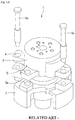
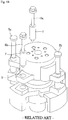
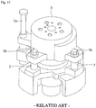
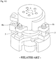
- Figs. 1A to 1G are views illustrating a method of assembling a fixed scroll with a main frame according to a related art.
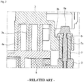
- Fig. 2 is a cross-sectional view of an assembly of the fixed scroll and the main frame which are assembled using the method according to the related art.
- an assembly 1 includes a plurality of coupling members 6a, 6b, and 6c, a main frame 2, and a fixed scroll 3, which are assembled with each other by a guide pin 7.
- the plurality of coupling members 6a, 6b, and 6c include a first coupling member 6a, a second coupling member 6b, and a third coupling member 6c.
- the guide pin 7 may surround a lower portion of each of the coupling members 6a, 6b, and 6c.
- the plurality of reference pins 5a and 5b include a first reference pin 5a and a second reference pin 5b.
- the main frame 2 includes a plurality of frame holes 2a, into which the plurality of reference pins 5a and 5b or the plurality of coupling members 6a, 6b, and 6c are inserted. That is, the plurality frame holes 2a may include holes, into which the plurality of reference pins 5a and 5b are inserted, and holes, into which the plurality of coupling members 6a, 6b, and 6c are inserted.
- the fixed scroll 3 includes a plurality of first holes 4, into which the plurality of reference pins 5a and 5b are inserted, and a plurality of second holes 5, into which the plurality of coupling members 6a, 6b, and 6c and the guide pin 7 are inserted.
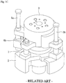
- the fixed scroll 3 is disposed on the main frame 2 so that the plurality of frame holes 2a and the plurality of first and second holes 4 and 5 are aligned with each other. Also, each of the first and second reference pins 5a and 5b passes through the first hole 4 of the fixed scroll 3 and then is inserted downward.
- each of lower portions of the first and second reference pins 5a and 5b may be inserted into the frame hole 2a of the main frame 2.
- the main frame 2 and the fixed scroll 3 may be fixed to or at predetermined positions without moving.
- each of the first and second coupling members 6a and 6b passes through the second hole 5 of the fixed scroll 3 and then is inserted downward.
- Each of the first and second coupling members 6a and 6b is coupled to the frame hole 2a of the main frame 2.
- a screw thread may be formed on each of the first and second coupling members 6a and 6b.
- each of the first and second coupling members 6a and 6b may be screw-coupled to the frame hole 2a of the main frame 2.
- a screw thread may be formed on an inner circumferential surface of the frame hole 2a.
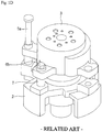
- the second reference pin 5b may be separated.
- a third coupling member 6c may be coupled to a position from which the second reference pin 5b is separated, that is, each of the first hole 4 of the fixed scroll 3 and the frame hole 2a of the main frame 2. That is, the second reference pin 5b may be separated, and then, the third coupling member 6c may be coupled to or at the separated position.
- the third coupling member 6c passes through the second hole 5 of the fixed scroll 3, and then is inserted downward, like the first and second coupling members 6a and 6b. Also, the third coupling member 6c is screw-coupled to the frame hole 2a of the main frame 2. Referring to Fig. 1G , in a state in which the main frame 2 and the fixed scroll 3 are assembled with the plurality of coupling members 6a, 6b, and 6c, the first reference pin 5a may be separated last.
- the frame assembly 1 assembled using the method according to the related art may have the following limitations.
- the main frame 2 or the fixed scroll 3 may be twisted, or the coupled portion may be deformed whenever the plurality of coupling members 6a, 6b, 6c is assembled.
- the main frame 2 and the fixed scroll 3 may be assembled with each other by the first coupling member 6a.
- fixed wrap 3a of the fixed scroll 3 may be closely attached to a head plate of orbiting scroll 8
- orbiting wrap 8a of the orbiting scroll 8 may be closely attached to the head plate of the fixed scroll 3.
- stress may be applied to the fixed scroll 3 in a predetermined direction by a coupling force of the first coupling member 6a. That is, the first coupling member 6a and the guide pin 7 may be closely attached to each other in a predetermined direction (a left direction in Fig. 2 ) within the second hole 5 of the fixed scroll 3.
- a deformed part or portion 3b may be formed in or at an inner circumferential surface of the second hole 5 of the fixed scroll 3 by the stress.
- the inner circumferential surface of the second hole 5, which is disposed in a direction opposite to the closely attached direction may be spaced apart from the guide pin 7. That is, a space 7a may be defined between the inner circumferential surface of the second hole 5 and an outer circumferential surface of the guide pin 7.
- the fixed scroll 3 may not easily move with respect to the main frame 2.
- the closely attached effect (a refrigerant leakage prevention effect) realized by the fixed scroll and the orbiting scroll due to the operation of the back pressure chamber may be reduced.
- EP 0 157 390 A2 relates to a scroll-type hydraulic machine in which a stationary scroll and an orbiting scroll cooperate with each other to compress a volume of fluid.
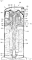
- Fig. 3 is a cross-sectional view of a scroll compressor according to an embodiment.
- Fig. 4 is an exploded, cut-away, cross-sectional view illustrating a portion of the scroll compressor according to an embodiment.
- Fig. 5 is a cross-sectional view illustrating a portion of the scroll compressor according to an embodiment.
- a scroll compressor 100 may include a casing 110 having a suction space S and a discharge space D.
- a cover 105 may be disposed in an inner upper portion of the casing 110.
- An inner space of the casing 110 may be partitioned into the suction space S and the discharge space D by the cover 105.
- An upper side of the cover 105 may correspond to the discharge space D, and a lower side of the cover 105 may correspond to the suction space S.
- a discharge hole 105a, through which a refrigerant compressed at or to a high pressure may be discharged, may be defined in an approximately central portion of the cover 105.
- the scroll compressor 100 may further include a suction port 101 that communicates with the suction space S, and a discharge port 103 that communicates with the discharge space D.
- Each of the suction port 101 and the discharge port 103 may be fixed to the casing 101 to allow the refrigerant to be suctioned into the casing 110 or discharged outside of the casing 110.
- a motor may be disposed at a lower portion of the suction space S.
- the motor may include a stator 112 coupled to an inner wall of the casing 110, a rotor 114 rotatably disposed within the stator 112, and a rotational shaft 116 that passes through a central portion of the stator 114.
- a lower portion of the rotational shaft 116 may be rotatably supported by an auxiliary bearing 117 disposed on or at a lower portion of the casing 110.
- the auxiliary bearing 117 may be coupled to a lower frame 118 to stably support the rotational shaft 116.
- the lower frame 118 may be fixed to the inner wall of the casing 110, and a bottom surface of the casing 110 may be used as an oil storage space. Oil stored in the oil storage space may be transferred upward by an oil supply passage 116a defined in the rotational shaft 116 and uniformly supplied in the casing 110.
- the oil supply passage 116a may be eccentrically disposed toward one side so that the oil introduced into the oil supply passage 116a flows upward by a centrifugal force generated by rotation of the rotational shaft 116.
- An upper portion of the rotational shaft 116 may be rotatably supported by a main frame 120.
- the main frame 120 may be fixed to the inner wall of the casing 110, similar to the lower frame 118.
- a main bearing 126 that protrudes downward may be disposed on a bottom surface of the main frame 120.
- the rotational shaft 116 may be inserted into the main bearing 126.
- An inner wall of the main bearing 126 may function as a bearing surface so that the rotational shaft 116 may smoothly rotate.
- An orbiting scroll 130 may be disposed on a top surface of the main frame 120.
- the orbiting scroll 130 may include an orbiting head plate 133 having an approximately disk shape and disposed on the main frame 120, and an orbiting wrap 134 having a spiral shape and extending from the orbiting head plate 133.
- the orbiting head plate 133 may define a lower portion of the orbiting scroll 130 and function as a main body of the orbiting scroll 130, and the orbiting wrap 134 may extend upward from the orbiting head plate 133 to define an upper portion of the orbiting scroll 130.
- the orbiting wrap 134 together with a fixed wrap 144, which will be described herein below, of a fixed scroll 140 may define a compression chamber.
- the orbiting scroll 130 may be referred to as a "first scroll”
- the fixed scroll 140 may be referred to as a "second scroll".
- the orbiting head plate 133 of the orbiting scroll 130 may revolve in a state in which the orbiting head plate 133 is supported on the top surface of the main frame 120.
- An Oldham ring 136 may be disposed between the orbiting head plate 133 and the main frame 120 to prevent the orbiting scroll 130 from revolving.
- a boss 138, into which an upper portion of the rotational shaft 116 may be inserted, may be disposed on a bottom surface of the orbiting head plate 133 of the orbiting scroll 130 to easily transmit a rotational force of the rotational shaft 116 to the orbiting scroll 130.
- the fixed scroll 140 engaged with the orbiting scroll 130 may be disposed on the orbiting scroll 130.
- the fixed scroll 140 may include a plurality of guides 141 that protrude from an outer circumferential surface of the fixed scroll 140 and each of which may have a guide hole 141 a, a guide pin 149 inserted into the guide hole 141 a and disposed on the top surface of the main frame 120, and a coupling member 146 inserted into the guide pin 149 and coupled to a frame guide hole 121a of the main frame 120.
- the fixed scroll 140 may further include a fixed head plate 143 having a disk shape, and the fixed wrap 144 that extends from the fixed head plate 143 toward the orbiting head plate 133 and which is engaged with the orbiting wrap 134 of the orbiting scroll 130.
- the fixed head plate 143 may define an upper portion of the fixed scroll 140 and function a main body of the fixed scroll 140, and the fixed wrap 144 may extend downward from the fixed head plate 143 to define a lower portion of the fixed scroll 140.
- the orbiting head plate 133 may be referred to as a "first head plate”
- the fixed head plate 143 may be referred to as a "second head plate”.
- the orbiting wrap 134 may be referred to as a "first wrap”
- the fixed wrap 144 may be referred to as a "second wrap”.
- An end of the fixed wrap 144 may be disposed to contact the orbiting head plate 133, and an end of the orbiting wrap 134 may be disposed to contact the fixed head plate 143.
- the fixed wrap 144 may extend in a predetermined spiral shape, and a discharge hole 145, through which the compressed refrigerant may be discharged, may defined in an approximately central portion of the fixed head plate 143.
- a suction hole (see reference numeral 196 of Fig. 8 ), through which the refrigerant within the suction space S maybe suctioned, may be defined in a side surface of the fixed scroll 140. The refrigerant suctioned through the suction hole 196 may be introduced into the compression chamber defined by the orbiting wrap 134 and the fixed wrap 144.
- the fixed wrap 144 and the orbiting wrap 134 may define a plurality of compression chambers.
- Each of the compression chambers may be reduced in volume while revolving and moving to the discharge hole-side to compress the refrigerant.
- the compression chamber adjacent to the suction hole 196 may be minimized in pressure, and the compression chamber that communicates with the discharge hole 145 may be maximized in pressure.
- the compression chamber between the above-described compression chambers may have an intermediate pressure that corresponds between a suction pressure of the suction hole 196 and a discharge pressure of the discharge hole 145.
- the intermediate pressure may be applied to a back pressure chamber BP, which will be described hereinbelow, to press the fixed scroll 140 toward the orbiting scroll 130.
- An intermediate pressure discharge hole 147 to transfer the refrigerant of the compression chamber having the intermediate pressure to the back pressure chamber BP may be defined in the fixed head plate 143 of the fixed scroll 140. That is, the intermediate pressure discharge hole 147 may be defined in a portion of the fixed scroll 130 at which the pressure in the compression chamber that communicates with the intermediate pressure discharge hole 147 is greater than the pressure in the suction space S and less than the pressure in the discharge space D.
- the intermediate pressure discharge hole 147 may pass from a top surface to a bottom surface of the fixed head plate 143.
- a back pressure chamber assembly 150 and 160 to define the back pressure chamber may be disposed on the fixed scroll 140.
- the back pressure chamber assembly 150 and 160 may include a back pressure part or portion 150, and a floating plate 160 separably coupled to the back pressure portion 150 and fixed to the upper portion of the fixed head plate 143 of the fixed scroll 140.
- the back pressure portion 150 may have an approximately annular shape with a hollow and include a support 152 that contacts the fixed head plate 143 of the fixed scroll 140.
- An intermediate pressure suction hole 153 that communicates with the intermediate pressure discharge hole 147 may be defined in the support 152.
- the intermediate pressure suction hole 153 may pass from a top surface to a bottom surface of the support 152.
- a second coupling hole 154 that communicates with a first coupling hole 148 defined in the fixed head plate 143 of the fixed scroll 140 may be defined in the support 152.
- the first coupling hole 148 and the second coupling hole 154 may be coupled to each other by a plate coupling member (see reference numeral 170 of Fig. 6 ).
- the back pressure portion 150 may include a plurality of walls 159 and 159 that extend upward from the support 152 and each of which has an approximately cylindrical shape.
- the plurality of walls 158 and 159 may include a first wall 158 that extends upward from an inner circumferential surface of the support 152, and a second wall 159 that extends upward from an outer circumferential surface of the support 152.
- Each of the first and second walls 158 and 159 may have an approximately cylindrical shape.
- the first and second walls 158 and 159 together with the support 152 may define a space having a predetermined shape.
- the space may define the above-described back pressure chamber BP.
- the first wall 158 may include a top surface 158a defining a top surface of the first wall 158.
- the first wall 158 may include at least one intermediate discharge hole 158b that communicates with the discharge hole 145 of the fixed head plate 143 to discharge the refrigerant discharged from the discharge hole 145 toward the cover 105.
- the at least one intermediate discharge hole 158b may include a plurality of intermediate discharge holes 158b that passes from a bottom surface of the first wall 158 to the top surface 158a.
- An inner space of the first wall 158 having a cylindrical shape may communicate with the discharge hole 145 to define a portion of a discharge passage to transfer the discharged refrigerant to the discharge space D.
- a discharge valve 108 having an approximately circular pillar shape may be disposed inside the first wall 158.
- the discharge valve 108 may be disposed on or in the discharge hole 145 and may have a size sufficient to completely cover the discharge hole 145. Thus, when the discharge valve 108 contacts the fixed head plate 143 of the fixed scroll 140, the discharge valve 108 may close the discharge hole 145.
- the discharge valve 108 may be movable upward or downward according to a variation in pressure applied to the discharge valve 108. Also, the inner circumferential surface of the first wall 158 may define a moving guide 158c to guide movement of the discharge valve 108.
- a discharge pressure apply hole 158d may be defined in the top surface 158a of the first wall 158.
- the discharge pressure apply hole 158d may communicate with the discharge hole 145.
- the discharge pressure apply hole 158d may be defined in an approximately central portion of the top surface 158a, and the plurality of intermediate discharge holes 158b may be disposed to surround the discharge pressure apply hole 158d.
- the pressure applied to the discharge pressure apply hole 158d may be greater than the discharge hole-side pressure. That is, the pressure may be applied downward to a top surface of the discharge valve 108, and thus, the discharge valve 108 may move downward to close the discharge hole 145.
- a discharge hole-side pressure may be greater than the pressure within the discharge space D.
- an upward pressure may be applied to a bottom surface of the discharge valve 108, and thus, the discharge valve 108 may move upward to open the discharge hole 145.
- the discharge hole 145 is opened, the refrigerant discharged from the discharge hole 145 may flow toward the cover 105 via the intermediate discharge hole 158b, and then, may be discharged outside of the compressor 100 through the discharge port 103 via the discharge hole 105a.
- the back pressure portion 150 may include a stepped portion 158e disposed inside a portion at which the first wall 158 and the support 152 are connected to each other.
- the refrigerant discharged from the discharge hole 145 may reach a space defined by the stepped portion 158e, and then, may flow to the intermediate discharge hole 158b.
- the second wall 159 may be spaced a predetermined distance outward from the first wall 158 to surround the first wall 158.
- the back pressure portion 150 may include a space having an approximately U-shaped cross-section formed by the first wall 158, the second wall 159, and the support 152.
- the floating plate 160 may be disposed in the space. A portion of the space covered by the floating plate 160 may define the back pressure chamber BP.
- a space defined by the first and second walls 158 and 159 of the back pressure portion 150, the support 152, and the floating plate 160 may define the back pressure chamber BP.
- the floating plate 160 may have an annular plate shape and include an inner circumferential surface that faces an outer circumferential surface of the first wall 158 and an outer circumferential surface that faces an inner circumferential surface of the second wall 159. That is, the inner circumferential surface of the floating plate 160 may be disposed to contact the outer circumferential surface of the first wall 158, and the outer circumferential surface of the floating plate 160 may be disposed to contact the inner circumferential surface of the second wall 159.
- 0-rings 159a and 161 may be disposed on or at contact portions between the floating plate 160 and the first and second walls 158 and 159, respectively.
- the 0-rings 159a and 161 may include a first O-ring 159a disposed on or at the contact portion between the inner circumferential surface of the second wall 159 and the outer circumferential surface of the floating plate 160, and a second O-ring 161 disposed on or at the contact portion between the outer circumferential surface of the first wall 158 and the inner circumferential surface of the floating plate 160.
- the first O-ring 159a may be disposed on the inner circumferential surface of the second wall 159
- the second O-ring 161 may be disposed on the inner circumferential surface of the floating plate 160. Refrigerant leakage through contact surfaces between the first and second walls 158 and 159 and the floating plate 160, that is, refrigerant leakage from the back pressure chamber BP may be prevented by the O-rings 159a and 161.
- a rib 164 that extends upward may be disposed on a top surface of the floating plate 160.
- the rib 164 may extend upward from the inner circumferential surface of the floating plate 160.
- the rib 164 may be movably disposed to selectively contact a bottom surface of the cover 105.
- the suction space S and the discharge space D may be partitioned.
- the suction space S and the discharge space D may communicate with each other.
- the floating plate 160 may move upward to allow the rib 164 to contact the bottom surface of the cover 105.
- the rib 164 may serve as a sealing member so that the refrigerant discharged from the discharge hole 145 to pass through the intermediate discharge hole 158b does not leak into the suction space S, but rather, is discharged into the discharge space D.
- the floating plate 160 may move downward to allow the rib 164 to be spaced apart from the bottom surface of the cover 105.
- the discharged refrigerant disposed at the discharge cover-side may flow toward the suction space S through the space between the rib 164 and the cover 105.
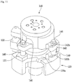
- Fig. 6 is an exploded perspective view illustrating a coupled structure of the fixed scroll and the back pressure portion according to an embodiment.
- Fig. 7 is a plan view of the fixed scroll according to an embodiment.
- the fixed scroll 140 may be coupled to a lower portion of a back pressure portion 150 by the plate coupling member 170.
- the fixed scroll 140 may include at least one first coupling hole 148 defined in the fixed head plate 143 and into which the plate coupling member 170 may be inserted.
- the plate coupling member 170 may pass through the second coupling hole 154 of the back pressure portion 150 to extend downward, and then, may be coupled to the first coupling hole 148.
- the at least one first coupling hole 148 may include a plurality of the first coupling holes 148.
- the plurality of first coupling holes 148 may be disposed to surround the discharge hole 145 defined in the approximately central portion of the fixed head plate 143.
- the fixed scroll 140 may include a plurality of coupling guides 141 and 142 to guiding coupling of the fixed scroll 140 and the main frame 120.
- the plurality of coupling guides 141 and 142 may be disposed to protrude outward from an outer circumferential surface of the fixed head plate 143. Also, the plurality of coupling guides 141 and 142 may be disposed to be spaced apart from each other.
- the plurality of coupling guides 141 and 142 may include a first coupling guide 141, to which the coupling member 146 may be coupled, and a second coupling guide 142 having a reference pin coupling hole 142b, to which each of reference pins 200a and 200b may be coupled.
- a plurality of the first coupling guide 141 may be provided, and the plurality of first coupling guides 141 may be disposed to face each other. Also, a plurality of the second coupling guide 142 may be provided, and the plurality of second coupling guides 142 may be disposed to face each other.
- first coupling guide 141 may be disposed between two second coupling guides 142
- second coupling guide 142 may be disposed between two first coupling guides 141.
- first coupling guides 141 and two second coupling guides 142 are provided in the drawings, the number of first and second coupling guides 141 and 142 may not be limited thereto.
- a first guide hole 141 a into which the coupling member 146 and a guide pin 149 may be inserted, may be defined in the first coupling guide 141.
- the guide pin 149 may be disposed to surround a lower portion of the coupling member 146.
- a second guide hole 142a, into which the coupling member 146 and the guide pin 149 may be inserted, and a reference pin coupling hole 142b, to which the first reference pin 200a may be coupled, may be defined in one of the plurality of second coupling guides 142.
- a reference pin coupling hole 142b, to which the second reference pin 200b may be coupled may be defined in the other one of the plurality of second coupling guides 142.
- the coupling member 146 coupled to the first guide hole 141 a may be referred to as a "first coupling member”
- the coupling member 146 coupled to the second guide hole 142a may be referred to as a "second coupling member”.
- the plurality of second coupling guides 142 having forms different from each other are illustrated in the drawings, embodiments are not limited thereto.
- the plurality of second coupling guides 142 may have a same form. That is, the second guide hole 142a and the reference pin coupling hole 142b may be defined in each of the plurality of second coupling guides 142.
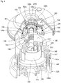
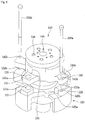
- Figs. 8 to 11 are views illustrating a method for assembling a fixed scroll with a main frame according to an embodiment.
- the main frame 120 may include a plurality of frame guides 121 and 122 that protrude outward from an outer circumferential surface of a main body 120a of the main frame 120.
- the plurality of frame guides 121 and 122 may be disposed to correspond to the first and second coupling guides 141 and 142 of the fixed scroll 140, respectively.
- the plurality of frame guides 121 and 122 may include a plurality of first frame guides 121 disposed to correspond to the plurality of first coupling guides 141, and a plurality of second frame guides 122 disposed to correspond to the plurality of second coupling guides 142.
- a first frame guide hole 121a, to which the coupling member (see the first coupling member 146) may be coupled, may be defined in each of the plurality of first frame guides 121.
- the coupling member 146 may pass through the first guide hole 141 a of the fixed scroll 140, and then, may be screw-coupled to the first frame guide hole 121 a.
- the guide pin 149 may pass through the first guide hole 141 a, and then, may be disposed on an upper portion of the first frame guide 121. That is, the guide pin 149 may have a diameter greater than an inner diameter of the first frame guide hole 121a. Thus, the guide pin 149 may be disposed above the first frame guide hole 121 a.
- a second frame guide hole 122a, into which the coupling member (see the second coupling member 146) may be inserted, and a reference pin coupling hole 122b, to which the first reference pin 200a may be coupled, may be defined in one of the plurality of second frame guides 122.
- a reference pin coupling hole 122b, to which a second reference pin 200b may be coupled, may be defined in the other one of the plurality of second frame guides 122.
- each of the second frame guides 122 may include the second frame guide hole 122a and the reference pin coupling hole 122b.
- the guide hole 142a and the reference pin coupling hole 142b may be defined in each of the plurality of second coupling guides 142.
- the reference pin coupling hole 142b may be referred to as a "first reference pin coupling hole”
- the reference pin coupling hole 122b may be referred to as a "second reference coupling hole”
- the fixed scroll 140 may be disposed above the main frame 120.
- the fixed scroll 140 may be disposed above the main frame 120 so that the plurality of first and second coupling guides 141 and 142 may correspond to the first and second frame guides 121 and 122.
- Each of the first and second reference pins 200a and 200b may pass through the first reference pin coupling hole 142b of the fixed scroll 140, and then may be inserted into the second reference pin coupling hole 122b of the main frame 120.
- each of the first and second reference pin coupling holes 122b and 142b may have a diameter greater than a diameter of each of the first and second reference pins 200a and 200b.
- the main frame 120 and the fixed scroll 140 may be maintained in an aligned state at a predetermined position (a centering position) without moving.
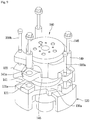
- the plurality of coupling members 146 may be, respectively, inserted into the first and second guide holes 141 a and 142a in astute in which each of the coupling members 146 is inserted into the guide pin 149.
- the guide pin 149 together with the coupling member 146 may be inserted into the first and second guide holes 141 a and 142a.
- the plurality of coupling members 146 may be inserted into the first and second frame guide holes 121 a and 122a, and then, may be coupled to the main frame 120. Also, the guide pin 149 may be seated on an upper portion of each of the first and second frame guides 121 and 122.
- three coupling members 146 may be inserted at a time into the first guide hole 141 a of the first coupling guide 141 and the second guide hole 142a of the second coupling guide 142. Also, the coupling member 146 passing through the first guide hole 141 a may be screw-coupled to the first frame guide hole 121a of the first frame guide 121, and the coupling member 146 passing through the second guide hole 142a may be screw-coupled to the second frame guide hole 122a of the second frame guide 122.
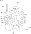
- first and second reference pins 200a and 200b inserted into the first and second reference pin coupling holes 122b and 142b are separated after the plurality of coupling members 146 are coupled, assembly of the main frame 120 and the fixed scroll 140 may be completed, as illustrated in Fig. 11 .
- the plurality of coupling members 146 may be coupled to the main frame 120 and the fixed scroll 140 through one process.
- the assembling process may be simplified. Also, when compared to when the plurality of coupling members are assembled through several processes, deformation or twisting of the coupled portion due to the coupling force of the coupling members may be prevented.
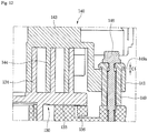
- Figs. 12 and 13 are cross-sectional views illustrating a coupled state of the fixed scroll and the main frame according to an embodiment.
- Fig. 12 illustrates a state in which the fixed scroll moves downward and then is closely attached to the orbiting head plate of the orbiting scroll.
- Fig. 13 illustrates a state in which the fixed scroll moves upward and then is spaced apart from the orbiting scroll.
- the orbiting wrap 134 of the orbiting scroll 130 may extend from the orbiting head plate 133 to the fixed head plate 143 of the fixed scroll 140, and the fixed wrap 144 of the fixed scroll 140 may extend from the fixed head plate 143 to the orbiting plate 133.
- the guide pin 149 may be supported by an upper portion of the main frame 120 in a state in which the guide pin 149 passes through the fixed scroll 140. The coupling member 146 may be inserted into the guide pin 149 and then screw-coupled to the main frame 120.
- the fixed scroll 140 may vertically move while the scroll compressor 100 operates or is stopped. For example, when the scroll compressor 100 initially operates in a state in which the scroll compressor 100 is stopped, the fixed scroll 140 may be lifted upward by the suction pressure of the refrigerant. An end of the orbiting wrap 134 of the orbiting scroll 130 may be spaced a distance C2 from the fixed head plate 143 of the fixed scroll 140. Also, an upper end of the first coupling guide 141 of the fixed scroll 140 may be disposed to contact a stepped portion 149a formed on an upper portion of the guide pin 149 (see Fig. 13 ).
- the back pressure chamber BP may be defined above the fixed scroll 140.
- the refrigerant having the intermediate pressure may be introduced into the back pressure chamber BP.
- the fixed scroll 140 may move downward by the pressure of the back pressure chamber BP, and thus, the fixed scroll 140 may be closely attached to the orbiting scroll 130.
- the stepped portion 149a of the guide pin 149 may be spaced a distance C1 from an upper end of the first coupling guide 141 of the fixed scroll 140.That is, the fixed wrap 144 of the fixed scroll 140 may be closely attached to the orbiting head plate 133 of the orbiting scroll 130, and the orbiting wrap 134 of the orbiting scroll 130 may be closely attached to the fixed head plate 143 of the fixed scroll 140.
- the fixed scroll includes the plurality of holes for respectively coupling the coupling member and the reference pin to the coupling portions that protrude outward from the fixed head plate, and the plurality of coupling portion may be coupled at once in a state in which the reference pin is inserted, assembling process of the frame assembly may be simplified, and productivity improved.
- the assembling process of the frame assembly is simplified so that the plurality of coupling members are coupled at once, automation of the assembling process may be easily realized. Furthermore, as the plurality of coupling members are coupled at once, twisting or deformation of the fixed scroll or the main frame during the assembling process may be prevented.
- Embodiments disclosed herein provide a scroll compressor in which a main frame and a fixed scroll may be easily assembled with each other.
- Embodiments disclosed herein provide a scroll compressor that may include a casing including a rotational shaft; a main frame coupled to an inside of the casing; a first scroll that revolves due to rotation of the rotational shaft, the first scroll being supported by the main frame; and a second scroll disposed on or at a side of the first scroll to define a plurality of compression chambers together with the first scroll.
- the second scroll may include a head plate including a wrap and a coupling guide part or guide that extends from the head plate.
- the coupling guide part may include a first reference pin coupling hole, into which a reference pin may be inserted, and a guide hole, into which a coupling member may be inserted.
- the main frame may include a main body, and a frame guide that extends from the main body.
- the frame guide may include a second reference coupling hole, into which the reference pin may be inserted, and a frame guide hole, into which the coupling member may be inserted.
- a plurality of the coupling guide part may be provided, and the plurality of coupling guide parts may be spaced apart from each other.
- a plurality of the frame guide part may be provided to correspond to the plurality of coupling guide parts.
- the plurality of coupling guide parts may include a first coupling guide part or guide having a first guide hole, into which a first coupling member may be inserted, and a second coupling guide part or guide having a second guide hole, into which a second coupling member may be inserted and the first reference pin coupling hole.
- the plurality of frame guide parts may include a first frame guide part or guide having a first frame guide hole, into which the first coupling member may be inserted, and a second frame guide part or guide having a second frame guide hole into which the second coupling member may be inserted and the second reference pin coupling hole.
- the coupling guide part may protrude outward from the head plate of the fixed scroll.
- the frame guide part may protrude outward from the main body of the main frame.
- the scroll compressor may further include a guide pin that surrounds a lower portion of the coupling member.
- the guide pin may pass through the guide hole of the second scroll and be supported by an upper portion of the main frame.
- Embodiments disclosed herein further provide a method for assembling a scroll compressor that may include disposing a second scroll on a main frame; inserting a reference pin into the main frame and the second scroll; coupling a plurality of coupling members to the main frame and the second scroll; and separating the reference pin from the main frame and the second scroll in a state in which the plurality of coupling members are coupled.
- the disposing of the second scroll on the main frame may include aligning a plurality of frame guide parts or guides formed on the main frame with a plurality of coupling guide parts or guides formed on the second scroll.
- the plurality of frame guide parts may protrude outward from the main frame, and the plurality of coupling guide parts may protrude outward from a second head plate of the second scroll.
- One coupling guide part of the plurality of coupling guide parts may include a first reference pin coupling hole, into which the reference pin may be inserted, and a guide hole, into which the coupling member may be inserted.
- At least one frame guide part of the plurality of frame guide parts may include a second reference pin coupling hole, into which the reference pin may be inserted, and a frame guide hole, into which the coupling member may be inserted.
- the inserting of the reference pin into the main frame and the second scroll may include inserting a plurality of reference pins into the main frame and the second scroll.
- the coupling of the plurality of coupling members to the main frame and the second scroll may include inserting the coupling members into the guide hole in a state in which the reference pin is coupled to the first reference pin coupling hole.
- the coupling of the plurality of coupling members to the main frame and the second scroll may include inserting the coupling members into the frame guide hole in a state in which the reference pin is coupled to the second reference pin coupling hole.
- any reference in this specification to "one embodiment,” “an embodiment,” “example embodiment,” etc. means that a particular feature, structure, or characteristic described in connection with the embodiment is included in at least one embodiment.
- the appearances of such phrases in various places in the specification are not necessarily all referring to the same embodiment.
Landscapes
- Engineering & Computer Science (AREA)
- Mechanical Engineering (AREA)
- General Engineering & Computer Science (AREA)
- Rotary Pumps (AREA)
Description
- A scroll compressor and a method for assembling a scroll compressor are disclosed herein.
- A scroll compressor is a compressor that includes a fixed scroll having a spiral wrap, and an orbiting scroll that revolves with respect to the fixed scroll, that is, a compressor in which the fixed scroll and the orbiting scroll are engaged with each other. The orbiting scroll revolves with respect to the fixed scroll, thereby reducing a volume of a compression chamber, which is formed between the fixed scroll and the orbiting scroll according to an orbiting motion of the orbiting scroll, thus increasing a pressure of a fluid, which is then discharged through a discharge hole formed in a central portion of the fixed scroll. Such a scroll compressor has a feature in which suction, compression, and a discharge of a fluid are successively performed while the orbiting scroll revolves. Accordingly, a discharge valve and a suction valve may be unnecessary in principle. Also, as a number of components of the scroll compressor is less in comparison to other types of compressor, the scroll compressor may be simplified in structure and rotate at a high speed. Also, as a variation in torque required for compression is less in comparison to other types of compressor, and suction and compression successively occur, a relatively small amount of noise and vibration may occur.
- One important issue in scroll compressors is leakage and lubrication between the fixing scroll and the orbiting scroll. That is, to prevent a refrigerant from leaking between the fixed scroll and the orbiting scroll, an end of a wrap has to be closely attached to a surface of a head plate to prevent compressed refrigerant from leaking. The term "head plate" may be refer to a portion that corresponds to a main body of the fixed scroll or the orbiting scroll. That is, the head plate of the fixed scroll may be closely attached to a wrap of the orbiting scroll (hereinafter, referred to as an "orbiting wrap"), and the head plate of the orbiting scroll may be closely attached to a wrap of the fixed scroll (hereinafter, referred to as a "fixed wrap").
- On the other hand, friction resistance has to be minimized so as to allow the orbiting scroll to smoothly revolve with respect to the fixed scroll. However, the leakage may conflict with the lubrication. That is, when the end of the wrap and the surface of the head plate are strongly attached to each other, it may be advantageous with respect to leakage, however, friction may increase, increasing damage due to noise and abrasion. On the other hand, when adhesion strength is low, the friction may be reduced, however, a sealing force may decrease, increasing the leakage.
- Thus, in the related art, a back pressure chamber having an intermediate pressure, which is defined as a value between a discharge pressure and a suction pressure, may be formed in or at a back surface of the orbiting scroll or the fixed scroll to solve the limitations with respect to sealing and friction reduction. That is, the back pressure chamber, which communicates with a compression chamber having an intermediate pressure of a plurality of compression chambers formed between the orbiting scroll and the fixed scroll, may be formed to allow the orbiting scroll and the fixed scroll to be adequately attached to each other, thereby solving the limitations with respect to leakage and lubrication.
- The back pressure chamber may be formed on a bottom surface of the orbiting scroll or a top surface of the fixed scroll. For convenience of description, the back pressure chamber formed on the bottom surface of the orbiting scroll and the back pressure chamber formed on the top surface of the fixed scroll may be referred to as a "lower back pressure type scroll compressor" and "an upper back pressure type scroll compressor", respectively. The lower back pressure type scroll compressor has advantages in that the lower back pressure type scroll compressor has a simple structure, and a bypass hole is easily formed. However, as the back pressure chamber is formed on the bottom surface of the orbiting scroll, which performs the orbiting motion, the back pressure chamber may change in configuration and position according to the orbiting motion. As a result, the orbiting scroll may be tilted, causing vibration and noise. In addition, an O-ring provided to prevent the refrigerant from leaking may be quickly worn out. The upper back pressure type scroll compressor has a relatively complicated structure. However, as the back pressure chamber is fixed in configuration and position, the fixed scroll may not be tilted, and sealing of the back pressure chamber may be good.
- The fixed scroll may be movably coupled to a main frame. The main frame refer to a part fixed to an inner wall of a casing that defines an outer appearance of the compressor. As the fixed scroll is movably coupled to the main frame, the fixed scroll and the orbiting scroll may be closely attached to each other by a force applied from the back pressure chamber.
-
Figs. 1A to 1G are views illustrating a method of assembling a fixed scroll with a main frame according to a related art.Fig. 2 is a cross-sectional view of an assembly of the fixed scroll and the main frame which are assembled using the method according to the related art. - Referring to
Figs. 1A and1B , anassembly 1 according to the related art includes a plurality ofcoupling members main frame 2, and afixed scroll 3, which are assembled with each other by aguide pin 7. The plurality ofcoupling members first coupling member 6a, asecond coupling member 6b, and athird coupling member 6c. Theguide pin 7 may surround a lower portion of each of thecoupling members - When the
main frame 2 and thefixed scroll 3 are assembled with each other, a plurality ofreference pins reference pins first reference pin 5a and asecond reference pin 5b. - In detail, referring to
Fig. 1A , themain frame 2 includes a plurality offrame holes 2a, into which the plurality ofreference pins coupling members plurality frame holes 2a may include holes, into which the plurality ofreference pins coupling members fixed scroll 3 includes a plurality offirst holes 4, into which the plurality ofreference pins second holes 5, into which the plurality ofcoupling members guide pin 7 are inserted. - Hereinafter, a method for assembling the
frame assembly 1 according to the related art will be described. - Referring to
Fig. 1A , thefixed scroll 3 is disposed on themain frame 2 so that the plurality offrame holes 2a and the plurality of first andsecond holes second reference pins first hole 4 of thefixed scroll 3 and then is inserted downward. - When the first and
second reference pins second reference pins frame hole 2a of themain frame 2. As described above, as the first andsecond reference pins fixed scroll 3 and themain frame 2, themain frame 2 and thefixed scroll 3 may be fixed to or at predetermined positions without moving. - Referring to
Figs. 1B and1C , in a state in which the first andsecond reference pins second coupling members second hole 5 of thefixed scroll 3 and then is inserted downward. Each of the first andsecond coupling members frame hole 2a of themain frame 2. - A screw thread may be formed on each of the first and
second coupling members second coupling members frame hole 2a of themain frame 2. Of course, a screw thread may be formed on an inner circumferential surface of theframe hole 2a. When the assembly of the first andsecond coupling members guide pin 7 may be disposed between thefixed scroll 3 and themain frame 2, in a state in which theguide pin 7 surrounds each of the first andsecond coupling members - Referring to
Figs. 1D and1F , in a state in which the assembly of the first andsecond coupling members second reference pin 5b may be separated. Also, athird coupling member 6c may be coupled to a position from which thesecond reference pin 5b is separated, that is, each of thefirst hole 4 of thefixed scroll 3 and theframe hole 2a of themain frame 2. That is, thesecond reference pin 5b may be separated, and then, thethird coupling member 6c may be coupled to or at the separated position. - The
third coupling member 6c passes through thesecond hole 5 of thefixed scroll 3, and then is inserted downward, like the first andsecond coupling members third coupling member 6c is screw-coupled to theframe hole 2a of themain frame 2. Referring toFig. 1G , in a state in which themain frame 2 and the fixedscroll 3 are assembled with the plurality ofcoupling members first reference pin 5a may be separated last. - The
frame assembly 1 assembled using the method according to the related art may have the following limitations. - As the plurality of
coupling members frame assembly 1 several times, themain frame 2 or the fixedscroll 3 may be twisted, or the coupled portion may be deformed whenever the plurality ofcoupling members Fig. 2 , themain frame 2 and the fixedscroll 3 may be assembled with each other by thefirst coupling member 6a. When themain frame 2 is assembled with the fixedscroll 3, fixedwrap 3a of the fixedscroll 3 may be closely attached to a head plate of orbitingscroll 8, and orbiting wrap 8a of theorbiting scroll 8 may be closely attached to the head plate of the fixedscroll 3. - When the
main frame 2 and the fixedscroll 3 are assembled with each other by the above-described method, stress may be applied to the fixedscroll 3 in a predetermined direction by a coupling force of thefirst coupling member 6a. That is, thefirst coupling member 6a and theguide pin 7 may be closely attached to each other in a predetermined direction (a left direction inFig. 2 ) within thesecond hole 5 of the fixedscroll 3. Thus, a deformed part orportion 3b may be formed in or at an inner circumferential surface of thesecond hole 5 of the fixedscroll 3 by the stress. - On the other hand, the inner circumferential surface of the
second hole 5, which is disposed in a direction opposite to the closely attached direction may be spaced apart from theguide pin 7. That is, aspace 7a may be defined between the inner circumferential surface of thesecond hole 5 and an outer circumferential surface of theguide pin 7. - As described above, in the state in which the
main frame 2 and the fixedscroll 3 are assembled with each other, if the stress is applied to form thedeformed portion 3b and thespace 7a in the fixedscroll 3, the fixedscroll 3 may not easily move with respect to themain frame 2. Thus, the closely attached effect (a refrigerant leakage prevention effect) realized by the fixed scroll and the orbiting scroll due to the operation of the back pressure chamber may be reduced. - Also, when the main frame and the fixed scroll are assembled with each other using the method according to the related art, the plurality of coupling members have to be assembled through several processes. Also, as a complicated process for assembling the coupling member after the reference pin is separated has to be performed, productivity of the frame assembly may be deteriorated.
EP 0 157 390 A2 - Embodiments will be described in detail with reference to the following drawings in which like reference numerals refer to like elements, and wherein:
-
Figs. 1A to 1G are views illustrating a method for assembling a fixed scroll with a main frame according to a related art; -
Fig. 2 is cross-sectional view illustrating an assembly of the fixed scroll and the main frame which are assembled with each other using the method according to the related art; -
Fig. 3 is a cross-sectional view of a scroll compressor according to an embodiment; -
Fig. 4 is an exploded, cut-away, cross-sectional view illustrating a portion of the scroll compressor according to an embodiment; -
Fig. 5 is a cross-sectional view illustrating a portion of the scroll compressor according to an embodiment; -
Fig. 6 is an exploded perspective view illustrating a coupled structure of the fixed scroll and a back pressure portion according to an embodiment; -
Fig. 7 is a plan view of the fixed scroll according to an embodiment; -
Figs. 8 to 11 are views illustrating a method for assembling the fixed scroll with a main frame according to an embodiment; and -
Figs. 12 and13 are cross-sectional views illustrating a coupled state of the fixed scroll and the main frame according to an embodiment. -
Fig. 3 is a cross-sectional view of a scroll compressor according to an embodiment.Fig. 4 is an exploded, cut-away, cross-sectional view illustrating a portion of the scroll compressor according to an embodiment.Fig. 5 is a cross-sectional view illustrating a portion of the scroll compressor according to an embodiment. - Referring to
Figs. 3 to 5 , ascroll compressor 100 according to an embodiment may include acasing 110 having a suction space S and a discharge spaceD. A cover 105 may be disposed in an inner upper portion of thecasing 110. An inner space of thecasing 110 may be partitioned into the suction space S and the discharge space D by thecover 105. An upper side of thecover 105 may correspond to the discharge space D, and a lower side of thecover 105 may correspond to the suction space S. Adischarge hole 105a, through which a refrigerant compressed at or to a high pressure may be discharged, may be defined in an approximately central portion of thecover 105. - The
scroll compressor 100 may further include asuction port 101 that communicates with the suction space S, and adischarge port 103 that communicates with the discharge space D. Each of thesuction port 101 and thedischarge port 103 may be fixed to thecasing 101 to allow the refrigerant to be suctioned into thecasing 110 or discharged outside of thecasing 110. - A motor may be disposed at a lower portion of the suction space S. The motor may include a
stator 112 coupled to an inner wall of thecasing 110, arotor 114 rotatably disposed within thestator 112, and arotational shaft 116 that passes through a central portion of thestator 114. - A lower portion of the
rotational shaft 116 may be rotatably supported by anauxiliary bearing 117 disposed on or at a lower portion of thecasing 110. Theauxiliary bearing 117 may be coupled to a lower frame 118 to stably support therotational shaft 116. - The lower frame 118 may be fixed to the inner wall of the
casing 110, and a bottom surface of thecasing 110 may be used as an oil storage space. Oil stored in the oil storage space may be transferred upward by anoil supply passage 116a defined in therotational shaft 116 and uniformly supplied in thecasing 110. Theoil supply passage 116a may be eccentrically disposed toward one side so that the oil introduced into theoil supply passage 116a flows upward by a centrifugal force generated by rotation of therotational shaft 116. - An upper portion of the
rotational shaft 116 may be rotatably supported by amain frame 120. Themain frame 120 may be fixed to the inner wall of thecasing 110, similar to the lower frame 118. Amain bearing 126 that protrudes downward may be disposed on a bottom surface of themain frame 120. Therotational shaft 116 may be inserted into themain bearing 126. An inner wall of themain bearing 126 may function as a bearing surface so that therotational shaft 116 may smoothly rotate. - An
orbiting scroll 130 may be disposed on a top surface of themain frame 120. Theorbiting scroll 130 may include an orbitinghead plate 133 having an approximately disk shape and disposed on themain frame 120, and anorbiting wrap 134 having a spiral shape and extending from the orbitinghead plate 133. The orbitinghead plate 133 may define a lower portion of theorbiting scroll 130 and function as a main body of theorbiting scroll 130, and theorbiting wrap 134 may extend upward from the orbitinghead plate 133 to define an upper portion of theorbiting scroll 130. Theorbiting wrap 134 together with a fixedwrap 144, which will be described herein below, of afixed scroll 140 may define a compression chamber. Theorbiting scroll 130 may be referred to as a "first scroll", and the fixedscroll 140 may be referred to as a "second scroll". - The orbiting
head plate 133 of theorbiting scroll 130 may revolve in a state in which the orbitinghead plate 133 is supported on the top surface of themain frame 120. AnOldham ring 136 may be disposed between the orbitinghead plate 133 and themain frame 120 to prevent the orbiting scroll 130 from revolving. Aboss 138, into which an upper portion of therotational shaft 116 may be inserted, may be disposed on a bottom surface of the orbitinghead plate 133 of theorbiting scroll 130 to easily transmit a rotational force of therotational shaft 116 to theorbiting scroll 130. The fixedscroll 140 engaged with theorbiting scroll 130 may be disposed on theorbiting scroll 130. - The fixed
scroll 140 may include a plurality ofguides 141 that protrude from an outer circumferential surface of the fixedscroll 140 and each of which may have aguide hole 141 a, aguide pin 149 inserted into theguide hole 141 a and disposed on the top surface of themain frame 120, and acoupling member 146 inserted into theguide pin 149 and coupled to aframe guide hole 121a of themain frame 120. The fixedscroll 140 may further include a fixedhead plate 143 having a disk shape, and the fixedwrap 144 that extends from the fixedhead plate 143 toward the orbitinghead plate 133 and which is engaged with the orbiting wrap 134 of theorbiting scroll 130. The fixedhead plate 143 may define an upper portion of the fixedscroll 140 and function a main body of the fixedscroll 140, and the fixedwrap 144 may extend downward from the fixedhead plate 143 to define a lower portion of the fixedscroll 140. For convenience of description, the orbitinghead plate 133 may be referred to as a "first head plate", and the fixedhead plate 143 may be referred to as a "second head plate". Further, theorbiting wrap 134 may be referred to as a "first wrap", and the fixedwrap 144 may be referred to as a "second wrap". - An end of the fixed
wrap 144 may be disposed to contact the orbitinghead plate 133, and an end of theorbiting wrap 134 may be disposed to contact the fixedhead plate 143. The fixedwrap 144 may extend in a predetermined spiral shape, and adischarge hole 145, through which the compressed refrigerant may be discharged, may defined in an approximately central portion of the fixedhead plate 143. A suction hole (seereference numeral 196 ofFig. 8 ), through which the refrigerant within the suction space S maybe suctioned, may be defined in a side surface of the fixedscroll 140. The refrigerant suctioned through thesuction hole 196 may be introduced into the compression chamber defined by theorbiting wrap 134 and the fixedwrap 144. - In detail, the fixed
wrap 144 and theorbiting wrap 134 may define a plurality of compression chambers. Each of the compression chambers may be reduced in volume while revolving and moving to the discharge hole-side to compress the refrigerant. Thus, the compression chamber adjacent to thesuction hole 196 may be minimized in pressure, and the compression chamber that communicates with thedischarge hole 145 may be maximized in pressure. Also, the compression chamber between the above-described compression chambers may have an intermediate pressure that corresponds between a suction pressure of thesuction hole 196 and a discharge pressure of thedischarge hole 145. The intermediate pressure may be applied to a back pressure chamber BP, which will be described hereinbelow, to press the fixedscroll 140 toward theorbiting scroll 130. - An intermediate
pressure discharge hole 147 to transfer the refrigerant of the compression chamber having the intermediate pressure to the back pressure chamber BP may be defined in the fixedhead plate 143 of the fixedscroll 140. That is, the intermediatepressure discharge hole 147 may be defined in a portion of the fixedscroll 130 at which the pressure in the compression chamber that communicates with the intermediatepressure discharge hole 147 is greater than the pressure in the suction space S and less than the pressure in the discharge space D. The intermediatepressure discharge hole 147 may pass from a top surface to a bottom surface of the fixedhead plate 143. - A back
pressure chamber assembly scroll 140. The backpressure chamber assembly portion 150, and a floatingplate 160 separably coupled to theback pressure portion 150 and fixed to the upper portion of the fixedhead plate 143 of the fixedscroll 140. - The
back pressure portion 150 may have an approximately annular shape with a hollow and include asupport 152 that contacts the fixedhead plate 143 of the fixedscroll 140. An intermediatepressure suction hole 153 that communicates with the intermediatepressure discharge hole 147 may be defined in thesupport 152. The intermediatepressure suction hole 153 may pass from a top surface to a bottom surface of thesupport 152. - A
second coupling hole 154 that communicates with afirst coupling hole 148 defined in the fixedhead plate 143 of the fixedscroll 140 may be defined in thesupport 152. Thefirst coupling hole 148 and thesecond coupling hole 154 may be coupled to each other by a plate coupling member (seereference numeral 170 ofFig. 6 ). - The
back pressure portion 150 may include a plurality ofwalls support 152 and each of which has an approximately cylindrical shape. The plurality ofwalls first wall 158 that extends upward from an inner circumferential surface of thesupport 152, and asecond wall 159 that extends upward from an outer circumferential surface of thesupport 152. Each of the first andsecond walls - The first and
second walls support 152 may define a space having a predetermined shape. The space may define the above-described back pressure chamber BP. - The
first wall 158 may include atop surface 158a defining a top surface of thefirst wall 158. Thefirst wall 158 may include at least oneintermediate discharge hole 158b that communicates with thedischarge hole 145 of the fixedhead plate 143 to discharge the refrigerant discharged from thedischarge hole 145 toward thecover 105. The at least oneintermediate discharge hole 158b may include a plurality of intermediate discharge holes 158b that passes from a bottom surface of thefirst wall 158 to thetop surface 158a. - An inner space of the
first wall 158 having a cylindrical shape may communicate with thedischarge hole 145 to define a portion of a discharge passage to transfer the discharged refrigerant to the discharge spaceD.A discharge valve 108 having an approximately circular pillar shape may be disposed inside thefirst wall 158. Thedischarge valve 108 may be disposed on or in thedischarge hole 145 and may have a size sufficient to completely cover thedischarge hole 145. Thus, when thedischarge valve 108 contacts the fixedhead plate 143 of the fixedscroll 140, thedischarge valve 108 may close thedischarge hole 145. - The
discharge valve 108 may be movable upward or downward according to a variation in pressure applied to thedischarge valve 108. Also, the inner circumferential surface of thefirst wall 158 may define a movingguide 158c to guide movement of thedischarge valve 108. - A discharge pressure apply
hole 158d may be defined in thetop surface 158a of thefirst wall 158. The discharge pressure applyhole 158d may communicate with thedischarge hole 145. The discharge pressure applyhole 158d may be defined in an approximately central portion of thetop surface 158a, and the plurality ofintermediate discharge holes 158b may be disposed to surround the discharge pressure applyhole 158d. - For example, when operation of the
scroll compressor 100 stops, if the refrigerant flows backward from the discharge space D toward thedischarge hole 145, the pressure applied to the discharge pressure applyhole 158d may be greater than the discharge hole-side pressure. That is, the pressure may be applied downward to a top surface of thedischarge valve 108, and thus, thedischarge valve 108 may move downward to close thedischarge hole 145. - On the other hand, when the
scroll compressor 100 operates to compress the refrigerant in the compression chamber, a discharge hole-side pressure may be greater than the pressure within the discharge space D. Thus, an upward pressure may be applied to a bottom surface of thedischarge valve 108, and thus, thedischarge valve 108 may move upward to open thedischarge hole 145. When thedischarge hole 145 is opened, the refrigerant discharged from thedischarge hole 145 may flow toward thecover 105 via theintermediate discharge hole 158b, and then, may be discharged outside of thecompressor 100 through thedischarge port 103 via thedischarge hole 105a. - The
back pressure portion 150 may include a steppedportion 158e disposed inside a portion at which thefirst wall 158 and thesupport 152 are connected to each other. The refrigerant discharged from thedischarge hole 145 may reach a space defined by the steppedportion 158e, and then, may flow to theintermediate discharge hole 158b. - The
second wall 159 may be spaced a predetermined distance outward from thefirst wall 158 to surround thefirst wall 158. - The
back pressure portion 150 may include a space having an approximately U-shaped cross-section formed by thefirst wall 158, thesecond wall 159, and thesupport 152. The floatingplate 160 may be disposed in the space. A portion of the space covered by the floatingplate 160 may define the back pressure chamber BP. On the other hand, a space defined by the first andsecond walls back pressure portion 150, thesupport 152, and the floatingplate 160 may define the back pressure chamber BP. - The floating
plate 160 may have an annular plate shape and include an inner circumferential surface that faces an outer circumferential surface of thefirst wall 158 and an outer circumferential surface that faces an inner circumferential surface of thesecond wall 159. That is, the inner circumferential surface of the floatingplate 160 may be disposed to contact the outer circumferential surface of thefirst wall 158, and the outer circumferential surface of the floatingplate 160 may be disposed to contact the inner circumferential surface of thesecond wall 159. - 0-
rings plate 160 and the first andsecond walls rings ring 159a disposed on or at the contact portion between the inner circumferential surface of thesecond wall 159 and the outer circumferential surface of the floatingplate 160, and a second O-ring 161 disposed on or at the contact portion between the outer circumferential surface of thefirst wall 158 and the inner circumferential surface of the floatingplate 160. For example, the first O-ring 159a may be disposed on the inner circumferential surface of thesecond wall 159, and the second O-ring 161 may be disposed on the inner circumferential surface of the floatingplate 160. Refrigerant leakage through contact surfaces between the first andsecond walls plate 160, that is, refrigerant leakage from the back pressure chamber BP may be prevented by the O-rings - A
rib 164 that extends upward may be disposed on a top surface of the floatingplate 160. For example, therib 164 may extend upward from the inner circumferential surface of the floatingplate 160. - The
rib 164 may be movably disposed to selectively contact a bottom surface of thecover 105. When therib 164 contacts thecover 105, the suction space S and the discharge space D may be partitioned. On the other hand, when therib 164 is spaced from the bottom surface of thecover 105, that is, when therib 164 moves in a direction away from thecover 105, the suction space S and the discharge space D may communicate with each other. - In detail, while the
scroll compressor 100 operates, the floatingplate 160 may move upward to allow therib 164 to contact the bottom surface of thecover 105. Thus, therib 164 may serve as a sealing member so that the refrigerant discharged from thedischarge hole 145 to pass through theintermediate discharge hole 158b does not leak into the suction space S, but rather, is discharged into the discharge space D. - On the other hand, when the
scroll compressor 100 stops, the floatingplate 160 may move downward to allow therib 164 to be spaced apart from the bottom surface of thecover 105. Thus, the discharged refrigerant disposed at the discharge cover-side may flow toward the suction space S through the space between therib 164 and thecover 105. -
Fig. 6 is an exploded perspective view illustrating a coupled structure of the fixed scroll and the back pressure portion according to an embodiment.Fig. 7 is a plan view of the fixed scroll according to an embodiment. - Referring to
Figs. 6 and7 , the fixedscroll 140 according to an embodiment may be coupled to a lower portion of aback pressure portion 150 by the plate coupling member 170.In detail, the fixedscroll 140 may include at least onefirst coupling hole 148 defined in the fixedhead plate 143 and into which theplate coupling member 170 may be inserted. Theplate coupling member 170 may pass through thesecond coupling hole 154 of theback pressure portion 150 to extend downward, and then, may be coupled to thefirst coupling hole 148. - The at least one
first coupling hole 148 may include a plurality of the first coupling holes 148. The plurality of first coupling holes 148 may be disposed to surround thedischarge hole 145 defined in the approximately central portion of the fixedhead plate 143. - The fixed
scroll 140 may include a plurality of coupling guides 141 and 142 to guiding coupling of the fixedscroll 140 and themain frame 120. The plurality of coupling guides 141 and 142 may be disposed to protrude outward from an outer circumferential surface of the fixedhead plate 143. Also, the plurality of coupling guides 141 and 142 may be disposed to be spaced apart from each other. - The plurality of coupling guides 141 and 142 may include a
first coupling guide 141, to which thecoupling member 146 may be coupled, and asecond coupling guide 142 having a referencepin coupling hole 142b, to which each ofreference pins - A plurality of the
first coupling guide 141 may be provided, and the plurality of first coupling guides 141 may be disposed to face each other. Also, a plurality of thesecond coupling guide 142 may be provided, and the plurality of second coupling guides 142 may be disposed to face each other. - For example, the
first coupling guide 141 may be disposed between two second coupling guides 142, and thesecond coupling guide 142 may be disposed between two first coupling guides 141. Although two first coupling guides 141 and two second coupling guides 142 are provided in the drawings, the number of first and second coupling guides 141 and 142 may not be limited thereto. - In detail, a
first guide hole 141 a, into which thecoupling member 146 and aguide pin 149 may be inserted, may be defined in thefirst coupling guide 141. Theguide pin 149 may be disposed to surround a lower portion of thecoupling member 146. - A
second guide hole 142a, into which thecoupling member 146 and theguide pin 149 may be inserted, and a referencepin coupling hole 142b, to which thefirst reference pin 200a may be coupled, may be defined in one of the plurality of second coupling guides 142. Also, a referencepin coupling hole 142b, to which thesecond reference pin 200b may be coupled, may be defined in the other one of the plurality of second coupling guides 142. For convenience of description, thecoupling member 146 coupled to thefirst guide hole 141 a may be referred to as a "first coupling member", and thecoupling member 146 coupled to thesecond guide hole 142a may be referred to as a "second coupling member". - As described above, although the plurality of second coupling guides 142 having forms different from each other are illustrated in the drawings, embodiments are not limited thereto. For example, the plurality of second coupling guides 142 may have a same form. That is, the
second guide hole 142a and the referencepin coupling hole 142b may be defined in each of the plurality of second coupling guides 142. - Hereinafter, a method for assembling the fixed
scroll 140 with themain frame 120 according to an embodiment will be described. -
Figs. 8 to 11 are views illustrating a method for assembling a fixed scroll with a main frame according to an embodiment. Referring toFig. 8 , themain frame 120 according to an embodiment may include a plurality of frame guides 121 and 122 that protrude outward from an outer circumferential surface of amain body 120a of themain frame 120. - The plurality of frame guides 121 and 122 may be disposed to correspond to the first and second coupling guides 141 and 142 of the fixed
scroll 140, respectively. In detail, the plurality of frame guides 121 and 122 may include a plurality of first frame guides 121 disposed to correspond to the plurality of first coupling guides 141, and a plurality of second frame guides 122 disposed to correspond to the plurality of second coupling guides 142. - A first
frame guide hole 121a, to which the coupling member (see the first coupling member 146) may be coupled, may be defined in each of the plurality of first frame guides 121. Thecoupling member 146 may pass through thefirst guide hole 141 a of the fixedscroll 140, and then, may be screw-coupled to the firstframe guide hole 121 a. - The
guide pin 149 may pass through thefirst guide hole 141 a, and then, may be disposed on an upper portion of thefirst frame guide 121. That is, theguide pin 149 may have a diameter greater than an inner diameter of the firstframe guide hole 121a. Thus, theguide pin 149 may be disposed above the firstframe guide hole 121 a. - A second
frame guide hole 122a, into which the coupling member (see the second coupling member 146) may be inserted, and a referencepin coupling hole 122b, to which thefirst reference pin 200a may be coupled, may be defined in one of the plurality of second frame guides 122. A referencepin coupling hole 122b, to which asecond reference pin 200b may be coupled, may be defined in the other one of the plurality of second frame guides 122. - As described above, although the plurality of second frame guides 122 having forms different from each other are illustrated in the drawings, embodiments not limited thereto. For example, the plurality of second frame guides 122 may have a same form. That is, each of the second frame guides 122 may include the second
frame guide hole 122a and the referencepin coupling hole 122b. Theguide hole 142a and the referencepin coupling hole 142b may be defined in each of the plurality of second coupling guides 142. For convenience of description, the referencepin coupling hole 142b may be referred to as a "first reference pin coupling hole", and the referencepin coupling hole 122b may be referred to as a "second reference coupling hole" - Hereinafter, an assembling method according to this embodiment will be described.
- Referring to
Fig. 8 , the fixedscroll 140 may be disposed above themain frame 120. The fixedscroll 140 may be disposed above themain frame 120 so that the plurality of first and second coupling guides 141 and 142 may correspond to the first and second frame guides 121 and 122. - Each of the first and
second reference pins pin coupling hole 142b of the fixedscroll 140, and then may be inserted into the second referencepin coupling hole 122b of themain frame 120. Of course, each of the first and second reference pin coupling holes 122b and 142b may have a diameter greater than a diameter of each of the first andsecond reference pins second reference pins main frame 120 and the fixedscroll 140 may be maintained in an aligned state at a predetermined position (a centering position) without moving. - Next, referring to
Figs. 9 and10 , the plurality ofcoupling members 146 may be, respectively, inserted into the first and second guide holes 141 a and 142a in astute in which each of thecoupling members 146 is inserted into theguide pin 149. Theguide pin 149 together with thecoupling member 146 may be inserted into the first and second guide holes 141 a and 142a. - The plurality of
coupling members 146 may be inserted into the first and second frame guide holes 121 a and 122a, and then, may be coupled to themain frame 120. Also, theguide pin 149 may be seated on an upper portion of each of the first and second frame guides 121 and 122. - For example, as illustrated in
Figs. 9 and10 , threecoupling members 146 may be inserted at a time into thefirst guide hole 141 a of thefirst coupling guide 141 and thesecond guide hole 142a of thesecond coupling guide 142. Also, thecoupling member 146 passing through thefirst guide hole 141 a may be screw-coupled to the firstframe guide hole 121a of thefirst frame guide 121, and thecoupling member 146 passing through thesecond guide hole 142a may be screw-coupled to the secondframe guide hole 122a of thesecond frame guide 122. - As described above, when the first and
second reference pins coupling members 146 are coupled, assembly of themain frame 120 and the fixedscroll 140 may be completed, as illustrated inFig. 11 . - According to the above-described assembling process, in a state in which the first and
second reference pins main frame 120 and the fixedscroll 140 to guide the coupling position, the plurality ofcoupling members 146 may be coupled to themain frame 120 and the fixedscroll 140 through one process. Thus, the assembling process may be simplified. Also, when compared to when the plurality of coupling members are assembled through several processes, deformation or twisting of the coupled portion due to the coupling force of the coupling members may be prevented. -
Figs. 12 and13 are cross-sectional views illustrating a coupled state of the fixed scroll and the main frame according to an embodiment.Fig. 12 illustrates a state in which the fixed scroll moves downward and then is closely attached to the orbiting head plate of the orbiting scroll.Fig. 13 illustrates a state in which the fixed scroll moves upward and then is spaced apart from the orbiting scroll. - Referring to
Figs. 12 and13 , in a state in which thecoupling member 146 according to an embodiment is coupled to themain frame 120 and the fixedscroll 140, the orbiting wrap 134 of theorbiting scroll 130 may extend from the orbitinghead plate 133 to the fixedhead plate 143 of the fixedscroll 140, and the fixedwrap 144 of the fixedscroll 140 may extend from the fixedhead plate 143 to the orbitingplate 133. Also, theguide pin 149 may be supported by an upper portion of themain frame 120 in a state in which theguide pin 149 passes through the fixedscroll 140. Thecoupling member 146 may be inserted into theguide pin 149 and then screw-coupled to themain frame 120. - The fixed
scroll 140 may vertically move while thescroll compressor 100 operates or is stopped. For example, when thescroll compressor 100 initially operates in a state in which thescroll compressor 100 is stopped, the fixedscroll 140 may be lifted upward by the suction pressure of the refrigerant. An end of the orbiting wrap 134 of theorbiting scroll 130 may be spaced a distance C2 from the fixedhead plate 143 of the fixedscroll 140. Also, an upper end of thefirst coupling guide 141 of the fixedscroll 140 may be disposed to contact a steppedportion 149a formed on an upper portion of the guide pin 149 (seeFig. 13 ). - The back pressure chamber BP may be defined above the fixed
scroll 140. When the refrigerant is compressed while thescroll compressor 100 operates, the refrigerant having the intermediate pressure may be introduced into the back pressure chamber BP. In this case, the fixedscroll 140 may move downward by the pressure of the back pressure chamber BP, and thus, the fixedscroll 140 may be closely attached to theorbiting scroll 130. - Also, as the
fixed scroll 140 moves, the steppedportion 149a of theguide pin 149 may be spaced a distance C1 from an upper end of thefirst coupling guide 141 of the fixed scroll 140.That is, the fixedwrap 144 of the fixedscroll 140 may be closely attached to the orbitinghead plate 133 of theorbiting scroll 130, and the orbiting wrap 134 of theorbiting scroll 130 may be closely attached to the fixedhead plate 143 of the fixedscroll 140. - Due to the above-described close attachment, a sealing effect of the compression chamber defined by the fixed
scroll 140 and theorbiting scroll 130 may be realized. Also, as described above, as thefixed scroll 140 is vertically movable with respect to themain frame 120, refrigerant leakage of the compression chamber may be prevented. - According to embodiments disclosed herein, as the fixed scroll includes the plurality of holes for respectively coupling the coupling member and the reference pin to the coupling portions that protrude outward from the fixed head plate, and the plurality of coupling portion may be coupled at once in a state in which the reference pin is inserted, assembling process of the frame assembly may be simplified, and productivity improved.
- Further, as the assembling process of the frame assembly is simplified so that the plurality of coupling members are coupled at once, automation of the assembling process may be easily realized. Furthermore, as the plurality of coupling members are coupled at once, twisting or deformation of the fixed scroll or the main frame during the assembling process may be prevented.
- Embodiments disclosed herein provide a scroll compressor in which a main frame and a fixed scroll may be easily assembled with each other.
- Embodiments disclosed herein provide a scroll compressor that may include a casing including a rotational shaft; a main frame coupled to an inside of the casing; a first scroll that revolves due to rotation of the rotational shaft, the first scroll being supported by the main frame; and a second scroll disposed on or at a side of the first scroll to define a plurality of compression chambers together with the first scroll. The second scroll may include a head plate including a wrap and a coupling guide part or guide that extends from the head plate. The coupling guide part may include a first reference pin coupling hole, into which a reference pin may be inserted, and a guide hole, into which a coupling member may be inserted.
- The main frame may include a main body, and a frame guide that extends from the main body. The frame guide may include a second reference coupling hole, into which the reference pin may be inserted, and a frame guide hole, into which the coupling member may be inserted. A plurality of the coupling guide part may be provided, and the plurality of coupling guide parts may be spaced apart from each other. A plurality of the frame guide part may be provided to correspond to the plurality of coupling guide parts.
- The plurality of coupling guide parts may include a first coupling guide part or guide having a first guide hole, into which a first coupling member may be inserted, and a second coupling guide part or guide having a second guide hole, into which a second coupling member may be inserted and the first reference pin coupling hole. The plurality of frame guide parts may include a first frame guide part or guide having a first frame guide hole, into which the first coupling member may be inserted, and a second frame guide part or guide having a second frame guide hole into which the second coupling member may be inserted and the second reference pin coupling hole.
- The coupling guide part may protrude outward from the head plate of the fixed scroll. The frame guide part may protrude outward from the main body of the main frame.
- The scroll compressor may further include a guide pin that surrounds a lower portion of the coupling member. The guide pin may pass through the guide hole of the second scroll and be supported by an upper portion of the main frame.
- Embodiments disclosed herein further provide a method for assembling a scroll compressor that may include disposing a second scroll on a main frame; inserting a reference pin into the main frame and the second scroll; coupling a plurality of coupling members to the main frame and the second scroll; and separating the reference pin from the main frame and the second scroll in a state in which the plurality of coupling members are coupled. The disposing of the second scroll on the main frame may include aligning a plurality of frame guide parts or guides formed on the main frame with a plurality of coupling guide parts or guides formed on the second scroll. The plurality of frame guide parts may protrude outward from the main frame, and the plurality of coupling guide parts may protrude outward from a second head plate of the second scroll.
- One coupling guide part of the plurality of coupling guide parts may include a first reference pin coupling hole, into which the reference pin may be inserted, and a guide hole, into which the coupling member may be inserted. At least one frame guide part of the plurality of frame guide parts may include a second reference pin coupling hole, into which the reference pin may be inserted, and a frame guide hole, into which the coupling member may be inserted.
- The inserting of the reference pin into the main frame and the second scroll may include inserting a plurality of reference pins into the main frame and the second scroll. The coupling of the plurality of coupling members to the main frame and the second scroll may include inserting the coupling members into the guide hole in a state in which the reference pin is coupled to the first reference pin coupling hole. The coupling of the plurality of coupling members to the main frame and the second scroll may include inserting the coupling members into the frame guide hole in a state in which the reference pin is coupled to the second reference pin coupling hole.
- The details of one or more embodiments are set forth in the accompanying drawings and the description. Other features will be apparent from the description and drawings, and from the claims.
- Although embodiments have been described with reference to a number of illustrative embodiments thereof, it should be understood that numerous other modifications and embodiments can be devised by those skilled in the art that will fall within the spirit and scope of the principles of this disclosure. More particularly, various variations and modifications are possible in the component parts and/or arrangements of the subject combination arrangement within the scope of the disclosure, the drawings and the appended claims. In addition to variations and modifications in the component parts and/or arrangements, alternative uses will also be apparent to those skilled in the art.
- Any reference in this specification to "one embodiment," "an embodiment," "example embodiment," etc., means that a particular feature, structure, or characteristic described in connection with the embodiment is included in at least one embodiment. The appearances of such phrases in various places in the specification are not necessarily all referring to the same embodiment. Further, when a particular feature, structure, or characteristic is described in connection with any embodiment, it is submitted that it is within the purview of one skilled in the art to effect such feature, structure, or characteristic in connection with other ones of the embodiments.
- Although embodiments have been described with reference to a number of illustrative embodiments thereof, it should be understood that numerous other modifications and embodiments can be devised by those skilled in the art that will fall within the spirit and scope of the principles of this disclosure. More particularly, various variations and modifications are possible in the component parts and/or arrangements of the subject combination arrangement within the scope of the disclosure, the drawings and the appended claims. In addition to variations and modifications in the component parts and/or arrangements, alternative uses will also be apparent to those skilled in the art.
Claims (14)
- A scroll compressor (100), comprising:a casing (110) comprising a rotational shaft (116);a main frame (120) coupled to an inside of the casing (110);a first scroll (130) that is revolved by rotation of the rotational shaft (116), the first scroll (130) being supported by the main frame (120); anda second scroll (140) disposed on or at a side of the first scroll (130) to define a plurality of compression chambers together with the first scroll (130), wherein the second scroll (140) comprises a head plate (143) including a wrap and at least one coupling guide (141, 142) that extends from the head plate (143), and wherein the at least one coupling guide (141, 142) includes a first reference pin coupling hole (142b), into which a reference pin (200a) is inserted, and a guide hole (141 a), into which a coupling member (146) is inserted,
characterised in that the main frame (120) comprises:a main body (120a); andat least one frame guide (121, 122) that extends from the main body (120a), the at least one frame guide (121, 122) having a second reference coupling hole (122b), into which the reference pin (200a) is inserted, and a frame guide hole (121a, 122a), into which the coupling member (146) is inserted. - The scroll compressor (100) according to claim 1, wherein the at least one coupling guide (141, 142) comprises a plurality of coupling guides (141, 142), and wherein the plurality of coupling guides (141, 142) is spaced apart from each other.
- The scroll compressor (100) according to claim 2, wherein the at least one frame guide (121, 122) comprises a plurality of frames guides (121a, 122a) corresponding to the plurality of coupling guides (141, 142).
- The scroll compressor (100) according to claim 2 or 3, wherein the plurality of coupling guides (141, 142) comprises:a first coupling guide (141) having a first coupling guide hole (141a), into which a first coupling member (146) is inserted; anda second coupling guide (142) having a second coupling guide hole (142), into which a second coupling member (146) is inserted.
- The scroll compressor (100) according to claim 3 or 4, wherein the plurality of frame guides (121, 122) comprises:a first frame guide (121) having a first frame guide hole (121a), into which the first coupling member (146) is inserted; anda second frame guide (122) having a second frame guide hole (122a), into which the second coupling member (146) is inserted.
- The scroll compressor (100) according to claim 5, wherein the first coupling member (146) passes through the first coupling guide hole (141a) and is screw-coupled to the first frame guide hole (121 a), and wherein the second coupling member (146) passes through the second coupling guide hole (142a) and is screw-coupled to the second frame guide hole (122a).
- The scroll compressor (100) according to any of claims 1 to 6, wherein the at least one coupling guide (141, 142) protrudes outward in a radial direction from the head plate (143) of the second scroll (140).
- The scroll compressor (100) according to any of claims 1 to 7, wherein the at least one frame guide (121, 122) protrudes outward in a radial direction from the main body (120a) of the main frame (120).
- The scroll compressor (100) according to any of claims 1 to 8, further comprising a guide pin (149) that surrounds a lower portion of the coupling member (146), wherein the guide pin (149) passes through the guide hole (141a) of the second scroll (140) and is supported by an upper portion of the main frame (120).
- The scroll compressor (100) according to any of claims 1 to 9, wherein the main frame (120) includes a second reference pin coupling hole (142b), into which the first and/or second reference pin (200a, 200b) is inserted, and wherein the first and/or second reference pin (200a, 200b) passes through the first reference pin coupling hole (142b) and is inserted into the second reference pin coupling hole (142b) of the main frame (120).
- A method for assembling a scroll compressor (100), the method comprising
disposing a scroll (130) on a main frame (120);
inserting at least one reference pin (200a, 200b) into the main frame (120) and the scroll (130);
coupling a plurality of coupling members (146) to the main frame (120) and the scroll (130); and
separating the at least one reference pin (200a, 200b) from the main frame (120) and the scroll (130) in a state in which the plurality of coupling members (146) is coupled. - The method according to claim 11, wherein the disposing of the scroll (130) on the main frame (120) comprises aligning a plurality of frame guides (121,122) formed on the main frame (120) with the plurality of coupling guides (141, 142) formed on the scroll (130).
- The method according to claim 12, wherein the plurality of frame guides (121, 122) protrudes outward in a radial direction from a body of the main frame (120), and wherein the plurality of coupling guides (141, 142) protrudes outward in the radial direction from a head plate (143) of the scroll (130).
- The method according to claim 12 or 13, wherein one coupling guide of the plurality of coupling guides (141, 142) comprises:a first reference pin coupling hole (142b), into which the reference pin (200a, 200b) is inserted; anda guide hole (141a), into which the coupling member (146) is inserted.
Applications Claiming Priority (1)
| Application Number | Priority Date | Filing Date | Title |
|---|---|---|---|
| KR1020140053653A KR102178050B1 (en) | 2014-05-02 | 2014-05-02 | A scroll compressor and a method assembling the same |
Publications (2)
| Publication Number | Publication Date |
|---|---|
| EP2942525A1 EP2942525A1 (en) | 2015-11-11 |
| EP2942525B1 true EP2942525B1 (en) | 2017-07-26 |
Family
ID=53015699
Family Applications (1)
| Application Number | Title | Priority Date | Filing Date |
|---|---|---|---|
| EP15165914.1A Active EP2942525B1 (en) | 2014-05-02 | 2015-04-30 | Scroll compressor and method for assembling a scroll compressor |
Country Status (4)
| Country | Link |
|---|---|
| US (1) | US9752578B2 (en) |
| EP (1) | EP2942525B1 (en) |
| KR (1) | KR102178050B1 (en) |
| CN (1) | CN105041656B (en) |
Families Citing this family (4)
| Publication number | Priority date | Publication date | Assignee | Title |
|---|---|---|---|---|
| US10927835B2 (en) | 2017-11-02 | 2021-02-23 | Emerson Climate Technologies, Inc. | Scroll compressor with scroll bolt clamp joint |
| KR102113228B1 (en) * | 2018-11-16 | 2020-05-20 | 엘지전자 주식회사 | Scroll compressor |
| JP6783844B2 (en) * | 2018-12-26 | 2020-11-11 | 本田技研工業株式会社 | Fastening structure of electrical members, fastening method of electrical members, and fastening / unfastening method of electrical members |
| JP7378264B2 (en) * | 2019-10-18 | 2023-11-13 | 三菱電機株式会社 | Scroll compressor, cycle device, and scroll compressor assembly method |
Family Cites Families (14)
| Publication number | Priority date | Publication date | Assignee | Title |
|---|---|---|---|---|
| JPS60206989A (en) | 1984-03-30 | 1985-10-18 | Mitsubishi Electric Corp | Scroll type fluid machine |
| US5102316A (en) * | 1986-08-22 | 1992-04-07 | Copeland Corporation | Non-orbiting scroll mounting arrangements for a scroll machine |
| JPH0626471A (en) | 1992-07-10 | 1994-02-01 | Toshiba Corp | Scroll compressor |
| AU6532094A (en) | 1994-01-26 | 1995-08-15 | Shimao Ni | Scroll-type fluid displacement device having high built-in volume ratio and semi-compliant biasing mechanism |
| TW381147B (en) * | 1994-07-22 | 2000-02-01 | Mitsubishi Electric Corp | Scroll compressor |
| US5496158A (en) * | 1994-12-22 | 1996-03-05 | Carrier Corporation | Drive for scroll compressor |
| JPH08200248A (en) * | 1995-01-30 | 1996-08-06 | Toshiba Corp | Scroll type compressor |
| JPH0932752A (en) * | 1995-07-17 | 1997-02-04 | Toshiba Corp | Scroll type compressor |
| US20050019194A1 (en) * | 2003-07-25 | 2005-01-27 | Rechi Precision Co., Ltd. | Scroll compressor pumping structure |
| US6896497B2 (en) | 2003-07-31 | 2005-05-24 | Rechi Precision Co., Ltd. | Axial compliant means for a scroll machine |
| US6984115B1 (en) | 2004-11-02 | 2006-01-10 | Chyn Tec. International Co., Ltd. | Axial sealing structure of scroll compressor |
| JP2013050079A (en) * | 2011-08-31 | 2013-03-14 | Sanyo Electric Co Ltd | Scroll compression equipment |
| CN202937451U (en) * | 2012-10-26 | 2013-05-15 | 复盛股份有限公司 | Fixing structure of compressor scroll with locating mechanism |
| CN203463290U (en) * | 2013-05-27 | 2014-03-05 | 珠海格力节能环保制冷技术研究中心有限公司 | Scroll compressor guiding and locating device and scroll compressor provided with same |
-
2014
- 2014-05-02 KR KR1020140053653A patent/KR102178050B1/en active IP Right Grant
-
2015
- 2015-04-23 US US14/693,946 patent/US9752578B2/en active Active
- 2015-04-30 EP EP15165914.1A patent/EP2942525B1/en active Active
- 2015-05-04 CN CN201510222217.1A patent/CN105041656B/en active Active
Non-Patent Citations (1)
| Title |
|---|
| None * |
Also Published As
| Publication number | Publication date |
|---|---|
| US9752578B2 (en) | 2017-09-05 |
| CN105041656A (en) | 2015-11-11 |
| KR20150126229A (en) | 2015-11-11 |
| CN105041656B (en) | 2018-03-09 |
| US20150316053A1 (en) | 2015-11-05 |
| KR102178050B1 (en) | 2020-11-12 |
| EP2942525A1 (en) | 2015-11-11 |
Similar Documents
| Publication | Publication Date | Title |
|---|---|---|
| EP2781755B1 (en) | Scroll compressor with back pressure chamber | |
| US9784271B2 (en) | Scroll compressor | |
| US9732752B2 (en) | Scroll compressor having a back pressure chamber assembly disposed on a fixed scroll plate and an elastic member disposed between a floating plate and a discharge cover | |
| US9726175B2 (en) | Scroll compressor having a back pressure plate and a gasket coupled to a fixed scroll plate by at least one coupling member | |
| EP2910785B1 (en) | Scroll compressor | |
| EP2942525B1 (en) | Scroll compressor and method for assembling a scroll compressor | |
| EP2762727B1 (en) | Scroll compressor | |
| WO2015162869A1 (en) | Scroll compressor | |
| JP6555543B2 (en) | Scroll compressor | |
| US9890861B2 (en) | Sealing member, scroll compressor including a sealing member and method for manufacturing a sealing member for a scroll compressor | |
| CN111373151B (en) | Scroll compressor having a discharge port for discharging refrigerant from a discharge chamber | |
| WO2017158665A1 (en) | Scroll compressor | |
| US20150316054A1 (en) | Scroll compressor | |
| US9970438B2 (en) | Scroll compressor | |
| EP3591231B1 (en) | Scroll compressor | |
| US20150316060A1 (en) | Compressor | |
| WO2016056174A1 (en) | Scroll compressor |
Legal Events
| Date | Code | Title | Description |
|---|---|---|---|
| PUAI | Public reference made under article 153(3) epc to a published international application that has entered the european phase |
Free format text: ORIGINAL CODE: 0009012 |
|
| 17P | Request for examination filed |
Effective date: 20150530 |
|
| AK | Designated contracting states |
Kind code of ref document: A1 Designated state(s): AL AT BE BG CH CY CZ DE DK EE ES FI FR GB GR HR HU IE IS IT LI LT LU LV MC MK MT NL NO PL PT RO RS SE SI SK SM TR |
|
| AX | Request for extension of the european patent |
Extension state: BA ME |
|
| RBV | Designated contracting states (corrected) |
Designated state(s): AL AT BE BG CH CY CZ DE DK EE ES FI FR GB GR HR HU IE IS IT LI LT LU LV MC MK MT NL NO PL PT RO RS SE SI SK SM TR |
|
| GRAP | Despatch of communication of intention to grant a patent |
Free format text: ORIGINAL CODE: EPIDOSNIGR1 |
|
| INTG | Intention to grant announced |
Effective date: 20170201 |
|
| GRAS | Grant fee paid |
Free format text: ORIGINAL CODE: EPIDOSNIGR3 |
|
| GRAA | (expected) grant |
Free format text: ORIGINAL CODE: 0009210 |
|
| AK | Designated contracting states |
Kind code of ref document: B1 Designated state(s): AL AT BE BG CH CY CZ DE DK EE ES FI FR GB GR HR HU IE IS IT LI LT LU LV MC MK MT NL NO PL PT RO RS SE SI SK SM TR |
|
| REG | Reference to a national code |
Ref country code: GB Ref legal event code: FG4D |
|
| REG | Reference to a national code |
Ref country code: CH Ref legal event code: EP |
|
| REG | Reference to a national code |
Ref country code: AT Ref legal event code: REF Ref document number: 912642 Country of ref document: AT Kind code of ref document: T Effective date: 20170815 |
|
| REG | Reference to a national code |
Ref country code: IE Ref legal event code: FG4D |
|
| REG | Reference to a national code |
Ref country code: DE Ref legal event code: R096 Ref document number: 602015003714 Country of ref document: DE |
|
| REG | Reference to a national code |
Ref country code: NL Ref legal event code: MP Effective date: 20170726 |
|
| REG | Reference to a national code |
Ref country code: LT Ref legal event code: MG4D |
|
| REG | Reference to a national code |
Ref country code: AT Ref legal event code: MK05 Ref document number: 912642 Country of ref document: AT Kind code of ref document: T Effective date: 20170726 |
|
| PG25 | Lapsed in a contracting state [announced via postgrant information from national office to epo] |
Ref country code: SE Free format text: LAPSE BECAUSE OF FAILURE TO SUBMIT A TRANSLATION OF THE DESCRIPTION OR TO PAY THE FEE WITHIN THE PRESCRIBED TIME-LIMIT Effective date: 20170726 Ref country code: AT Free format text: LAPSE BECAUSE OF FAILURE TO SUBMIT A TRANSLATION OF THE DESCRIPTION OR TO PAY THE FEE WITHIN THE PRESCRIBED TIME-LIMIT Effective date: 20170726 Ref country code: HR Free format text: LAPSE BECAUSE OF FAILURE TO SUBMIT A TRANSLATION OF THE DESCRIPTION OR TO PAY THE FEE WITHIN THE PRESCRIBED TIME-LIMIT Effective date: 20170726 Ref country code: NL Free format text: LAPSE BECAUSE OF FAILURE TO SUBMIT A TRANSLATION OF THE DESCRIPTION OR TO PAY THE FEE WITHIN THE PRESCRIBED TIME-LIMIT Effective date: 20170726 Ref country code: LT Free format text: LAPSE BECAUSE OF FAILURE TO SUBMIT A TRANSLATION OF THE DESCRIPTION OR TO PAY THE FEE WITHIN THE PRESCRIBED TIME-LIMIT Effective date: 20170726 Ref country code: FI Free format text: LAPSE BECAUSE OF FAILURE TO SUBMIT A TRANSLATION OF THE DESCRIPTION OR TO PAY THE FEE WITHIN THE PRESCRIBED TIME-LIMIT Effective date: 20170726 Ref country code: NO Free format text: LAPSE BECAUSE OF FAILURE TO SUBMIT A TRANSLATION OF THE DESCRIPTION OR TO PAY THE FEE WITHIN THE PRESCRIBED TIME-LIMIT Effective date: 20171026 |
|
| PG25 | Lapsed in a contracting state [announced via postgrant information from national office to epo] |
Ref country code: PL Free format text: LAPSE BECAUSE OF FAILURE TO SUBMIT A TRANSLATION OF THE DESCRIPTION OR TO PAY THE FEE WITHIN THE PRESCRIBED TIME-LIMIT Effective date: 20170726 Ref country code: BG Free format text: LAPSE BECAUSE OF FAILURE TO SUBMIT A TRANSLATION OF THE DESCRIPTION OR TO PAY THE FEE WITHIN THE PRESCRIBED TIME-LIMIT Effective date: 20171026 Ref country code: LV Free format text: LAPSE BECAUSE OF FAILURE TO SUBMIT A TRANSLATION OF THE DESCRIPTION OR TO PAY THE FEE WITHIN THE PRESCRIBED TIME-LIMIT Effective date: 20170726 Ref country code: IS Free format text: LAPSE BECAUSE OF FAILURE TO SUBMIT A TRANSLATION OF THE DESCRIPTION OR TO PAY THE FEE WITHIN THE PRESCRIBED TIME-LIMIT Effective date: 20171126 Ref country code: RS Free format text: LAPSE BECAUSE OF FAILURE TO SUBMIT A TRANSLATION OF THE DESCRIPTION OR TO PAY THE FEE WITHIN THE PRESCRIBED TIME-LIMIT Effective date: 20170726 Ref country code: ES Free format text: LAPSE BECAUSE OF FAILURE TO SUBMIT A TRANSLATION OF THE DESCRIPTION OR TO PAY THE FEE WITHIN THE PRESCRIBED TIME-LIMIT Effective date: 20170726 Ref country code: GR Free format text: LAPSE BECAUSE OF FAILURE TO SUBMIT A TRANSLATION OF THE DESCRIPTION OR TO PAY THE FEE WITHIN THE PRESCRIBED TIME-LIMIT Effective date: 20171027 |
|
| PG25 | Lapsed in a contracting state [announced via postgrant information from national office to epo] |
Ref country code: CZ Free format text: LAPSE BECAUSE OF FAILURE TO SUBMIT A TRANSLATION OF THE DESCRIPTION OR TO PAY THE FEE WITHIN THE PRESCRIBED TIME-LIMIT Effective date: 20170726 Ref country code: RO Free format text: LAPSE BECAUSE OF FAILURE TO SUBMIT A TRANSLATION OF THE DESCRIPTION OR TO PAY THE FEE WITHIN THE PRESCRIBED TIME-LIMIT Effective date: 20170726 Ref country code: DK Free format text: LAPSE BECAUSE OF FAILURE TO SUBMIT A TRANSLATION OF THE DESCRIPTION OR TO PAY THE FEE WITHIN THE PRESCRIBED TIME-LIMIT Effective date: 20170726 |
|
| REG | Reference to a national code |
Ref country code: DE Ref legal event code: R097 Ref document number: 602015003714 Country of ref document: DE |
|
| PG25 | Lapsed in a contracting state [announced via postgrant information from national office to epo] |
Ref country code: EE Free format text: LAPSE BECAUSE OF FAILURE TO SUBMIT A TRANSLATION OF THE DESCRIPTION OR TO PAY THE FEE WITHIN THE PRESCRIBED TIME-LIMIT Effective date: 20170726 Ref country code: SK Free format text: LAPSE BECAUSE OF FAILURE TO SUBMIT A TRANSLATION OF THE DESCRIPTION OR TO PAY THE FEE WITHIN THE PRESCRIBED TIME-LIMIT Effective date: 20170726 Ref country code: SM Free format text: LAPSE BECAUSE OF FAILURE TO SUBMIT A TRANSLATION OF THE DESCRIPTION OR TO PAY THE FEE WITHIN THE PRESCRIBED TIME-LIMIT Effective date: 20170726 Ref country code: IT Free format text: LAPSE BECAUSE OF FAILURE TO SUBMIT A TRANSLATION OF THE DESCRIPTION OR TO PAY THE FEE WITHIN THE PRESCRIBED TIME-LIMIT Effective date: 20170726 |
|
| PLBE | No opposition filed within time limit |
Free format text: ORIGINAL CODE: 0009261 |
|
| STAA | Information on the status of an ep patent application or granted ep patent |
Free format text: STATUS: NO OPPOSITION FILED WITHIN TIME LIMIT |
|
| 26N | No opposition filed |
Effective date: 20180430 |
|
| PG25 | Lapsed in a contracting state [announced via postgrant information from national office to epo] |
Ref country code: SI Free format text: LAPSE BECAUSE OF FAILURE TO SUBMIT A TRANSLATION OF THE DESCRIPTION OR TO PAY THE FEE WITHIN THE PRESCRIBED TIME-LIMIT Effective date: 20170726 |
|
| PG25 | Lapsed in a contracting state [announced via postgrant information from national office to epo] |
Ref country code: MC Free format text: LAPSE BECAUSE OF FAILURE TO SUBMIT A TRANSLATION OF THE DESCRIPTION OR TO PAY THE FEE WITHIN THE PRESCRIBED TIME-LIMIT Effective date: 20170726 |
|
| REG | Reference to a national code |
Ref country code: CH Ref legal event code: PL |
|
| REG | Reference to a national code |
Ref country code: BE Ref legal event code: MM Effective date: 20180430 |
|
| REG | Reference to a national code |
Ref country code: IE Ref legal event code: MM4A |
|
| PG25 | Lapsed in a contracting state [announced via postgrant information from national office to epo] |
Ref country code: LU Free format text: LAPSE BECAUSE OF NON-PAYMENT OF DUE FEES Effective date: 20180430 |
|
| PG25 | Lapsed in a contracting state [announced via postgrant information from national office to epo] |
Ref country code: CH Free format text: LAPSE BECAUSE OF NON-PAYMENT OF DUE FEES Effective date: 20180430 Ref country code: BE Free format text: LAPSE BECAUSE OF NON-PAYMENT OF DUE FEES Effective date: 20180430 Ref country code: LI Free format text: LAPSE BECAUSE OF NON-PAYMENT OF DUE FEES Effective date: 20180430 |
|
| PG25 | Lapsed in a contracting state [announced via postgrant information from national office to epo] |
Ref country code: IE Free format text: LAPSE BECAUSE OF NON-PAYMENT OF DUE FEES Effective date: 20180430 Ref country code: FR Free format text: LAPSE BECAUSE OF NON-PAYMENT OF DUE FEES Effective date: 20180430 |
|
| GBPC | Gb: european patent ceased through non-payment of renewal fee |
Effective date: 20190430 |
|
| PG25 | Lapsed in a contracting state [announced via postgrant information from national office to epo] |
Ref country code: MT Free format text: LAPSE BECAUSE OF NON-PAYMENT OF DUE FEES Effective date: 20180430 Ref country code: GB Free format text: LAPSE BECAUSE OF NON-PAYMENT OF DUE FEES Effective date: 20190430 |
|
| PG25 | Lapsed in a contracting state [announced via postgrant information from national office to epo] |
Ref country code: TR Free format text: LAPSE BECAUSE OF FAILURE TO SUBMIT A TRANSLATION OF THE DESCRIPTION OR TO PAY THE FEE WITHIN THE PRESCRIBED TIME-LIMIT Effective date: 20170726 |
|
| PG25 | Lapsed in a contracting state [announced via postgrant information from national office to epo] |
Ref country code: PT Free format text: LAPSE BECAUSE OF FAILURE TO SUBMIT A TRANSLATION OF THE DESCRIPTION OR TO PAY THE FEE WITHIN THE PRESCRIBED TIME-LIMIT Effective date: 20170726 |
|
| PG25 | Lapsed in a contracting state [announced via postgrant information from national office to epo] |
Ref country code: CY Free format text: LAPSE BECAUSE OF FAILURE TO SUBMIT A TRANSLATION OF THE DESCRIPTION OR TO PAY THE FEE WITHIN THE PRESCRIBED TIME-LIMIT Effective date: 20170726 Ref country code: HU Free format text: LAPSE BECAUSE OF FAILURE TO SUBMIT A TRANSLATION OF THE DESCRIPTION OR TO PAY THE FEE WITHIN THE PRESCRIBED TIME-LIMIT; INVALID AB INITIO Effective date: 20150430 Ref country code: MK Free format text: LAPSE BECAUSE OF NON-PAYMENT OF DUE FEES Effective date: 20170726 |
|
| PG25 | Lapsed in a contracting state [announced via postgrant information from national office to epo] |
Ref country code: AL Free format text: LAPSE BECAUSE OF FAILURE TO SUBMIT A TRANSLATION OF THE DESCRIPTION OR TO PAY THE FEE WITHIN THE PRESCRIBED TIME-LIMIT Effective date: 20170726 |
|
| PGFP | Annual fee paid to national office [announced via postgrant information from national office to epo] |
Ref country code: DE Payment date: 20240305 Year of fee payment: 10 |