EP2942516A1 - Method to determine the injection pattern in the compression stroke of the combustion cycle of the cylinders of a direct-injection internal combustion engine - Google Patents
Method to determine the injection pattern in the compression stroke of the combustion cycle of the cylinders of a direct-injection internal combustion engine Download PDFInfo
- Publication number
- EP2942516A1 EP2942516A1 EP15167047.8A EP15167047A EP2942516A1 EP 2942516 A1 EP2942516 A1 EP 2942516A1 EP 15167047 A EP15167047 A EP 15167047A EP 2942516 A1 EP2942516 A1 EP 2942516A1
- Authority
- EP
- European Patent Office
- Prior art keywords
- comp
- fuel
- injected
- injection
- partial
- Prior art date
- Legal status (The legal status is an assumption and is not a legal conclusion. Google has not performed a legal analysis and makes no representation as to the accuracy of the status listed.)
- Granted
Links
Images



Classifications
-
- F—MECHANICAL ENGINEERING; LIGHTING; HEATING; WEAPONS; BLASTING
- F02—COMBUSTION ENGINES; HOT-GAS OR COMBUSTION-PRODUCT ENGINE PLANTS
- F02M—SUPPLYING COMBUSTION ENGINES IN GENERAL WITH COMBUSTIBLE MIXTURES OR CONSTITUENTS THEREOF
- F02M65/00—Testing fuel-injection apparatus, e.g. testing injection timing ; Cleaning of fuel-injection apparatus
- F02M65/001—Measuring fuel delivery of a fuel injector
-
- F—MECHANICAL ENGINEERING; LIGHTING; HEATING; WEAPONS; BLASTING
- F02—COMBUSTION ENGINES; HOT-GAS OR COMBUSTION-PRODUCT ENGINE PLANTS
- F02D—CONTROLLING COMBUSTION ENGINES
- F02D41/00—Electrical control of supply of combustible mixture or its constituents
- F02D41/30—Controlling fuel injection
- F02D41/38—Controlling fuel injection of the high pressure type
- F02D41/40—Controlling fuel injection of the high pressure type with means for controlling injection timing or duration
- F02D41/402—Multiple injections
-
- F—MECHANICAL ENGINEERING; LIGHTING; HEATING; WEAPONS; BLASTING
- F02—COMBUSTION ENGINES; HOT-GAS OR COMBUSTION-PRODUCT ENGINE PLANTS
- F02D—CONTROLLING COMBUSTION ENGINES
- F02D41/00—Electrical control of supply of combustible mixture or its constituents
- F02D41/30—Controlling fuel injection
- F02D41/3005—Details not otherwise provided for
-
- F—MECHANICAL ENGINEERING; LIGHTING; HEATING; WEAPONS; BLASTING
- F02—COMBUSTION ENGINES; HOT-GAS OR COMBUSTION-PRODUCT ENGINE PLANTS
- F02D—CONTROLLING COMBUSTION ENGINES
- F02D41/00—Electrical control of supply of combustible mixture or its constituents
- F02D41/02—Circuit arrangements for generating control signals
- F02D41/04—Introducing corrections for particular operating conditions
- F02D41/06—Introducing corrections for particular operating conditions for engine starting or warming up
-
- F—MECHANICAL ENGINEERING; LIGHTING; HEATING; WEAPONS; BLASTING
- F02—COMBUSTION ENGINES; HOT-GAS OR COMBUSTION-PRODUCT ENGINE PLANTS
- F02D—CONTROLLING COMBUSTION ENGINES
- F02D41/00—Electrical control of supply of combustible mixture or its constituents
- F02D41/24—Electrical control of supply of combustible mixture or its constituents characterised by the use of digital means
- F02D41/2406—Electrical control of supply of combustible mixture or its constituents characterised by the use of digital means using essentially read only memories
- F02D41/2425—Particular ways of programming the data
- F02D41/2429—Methods of calibrating or learning
- F02D41/2451—Methods of calibrating or learning characterised by what is learned or calibrated
- F02D41/2464—Characteristics of actuators
- F02D41/2467—Characteristics of actuators for injectors
- F02D41/247—Behaviour for small quantities
-
- Y—GENERAL TAGGING OF NEW TECHNOLOGICAL DEVELOPMENTS; GENERAL TAGGING OF CROSS-SECTIONAL TECHNOLOGIES SPANNING OVER SEVERAL SECTIONS OF THE IPC; TECHNICAL SUBJECTS COVERED BY FORMER USPC CROSS-REFERENCE ART COLLECTIONS [XRACs] AND DIGESTS
- Y02—TECHNOLOGIES OR APPLICATIONS FOR MITIGATION OR ADAPTATION AGAINST CLIMATE CHANGE
- Y02T—CLIMATE CHANGE MITIGATION TECHNOLOGIES RELATED TO TRANSPORTATION
- Y02T10/00—Road transport of goods or passengers
- Y02T10/10—Internal combustion engine [ICE] based vehicles
- Y02T10/40—Engine management systems
Definitions
- the present invention relates to a method to determine the injection pattern in the compression stroke of the combustion cycle of the cylinders of a direct-injection internal combustion engine.
- a spark-ignited, direct-injection internal combustion engine comprises a number of cylinders, each of which is provided with a respective piston, which cyclically slides within the cylinder and is mechanically connected by means of a connecting rod to a crankshaft to transmit to the drive shaft itself the force generated by the combustion within the cylinder, with a respective injector partially arranged inside the cylinder and with a respective spark plug, which is cyclically controlled by an electronic control unit to produce a spark between its electrodes and thus determine the ignition of the compressed gases in the cylinder itself.
- the internal combustion engine further comprises an intake manifold, which is connected to each cylinder by means of one or more intake valves, and an exhaust manifold, which is connected to each cylinder by means of one or more exhaust valves and which leads to an emission pipe to emit the gases produced by the combustion into the atmosphere.
- the four-stroke combustion cycle of each cylinder consists of four strokes in sequence: an intake stroke, a compression stroke, an expansion stroke and an exhaust stroke. At the end of each combustion cycle, two complete revolutions will have been completed by the drive shaft, thus covering a rotation equal to 720°.
- the piston is initially at top dead center and, during the intake stroke, descends to bottom dead center by generating a vacuum in the cylinder which, as the respective intake valve opens, recalls air from the intake pipe covering half a revolution of the drive shaft and exploring an angle from 0° to 180°.
- Fuel is injected in the combustion chamber during the intake stroke and/or during the subsequent compression stroke.
- the electrodes of the spark plug produce the spark which ignites the air and fuel mixture in the cylinder starting the combustion itself, which produces an increase of temperature and pressure in addition to being the only step of the combustion cycle in which useful work is generated.
- the piston is pushed from top dead center to bottom dead center by covering half a revolution of the drive shaft and exploring an angle from 360° to 540°.
- the piston is at bottom dead center again and moves up to top dead center to eject the burnt gases, which are introduced into the exhaust pipe, by means of the respective exhaust valve, covering half a revolution of the drive shaft and exploring an angle from 540° to 720°.
- the overall quantity of fuel to be injected for each four-stroke combustion cycle can be determined as a function of the torque to be delivered to the drive wheels which determines the quantity of air that the engine must aspirate.
- the overall quantity of fuel to be injected for each four-stroke combustion cycle of each cylinder may be injected, alternatively, either during the intake stroke, or during the compression stroke, or even during both the intake stroke and the compression stroke.
- the definition of the injection pattern i.e. the determination of the stroke or strokes of the combustion cycle during which the quantity of fuel is either completely or partially injected
- the definition of the injection pattern is extremely critical to be able guarantee a correct mixing of air and fuel and to prevent the fuel from fouling the crown of the piston or the walls of the cylinder and causing the formation of particulate.
- a control unit and a method for determining the injection pattern in the combustion stroke of the combustion cycle of the cylinders of a direct-injection internal combustion engine are provided as disclosed in the appended claims.
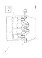
- reference numeral 1 indicates as a whole a spark-ignited internal combustion engine comprising four cylinders 2 in a straight arrangement.
- Each cylinder 2 comprises a respective piston 3 mechanically connected by means of a connecting rod to a crankshaft 4 for transmitting the force generated by the combustion in the cylinder 2 to the drive shaft 4 itself.
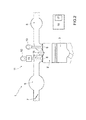
- the internal combustion engine 1 comprises an intake manifold 5, which is connected to each cylinder 2 by means of two intake valves 6 (of which only one is shown in figure 2 ) and receives fresh air (i.e. air from the outside environment) through a butterfly valve 7 moveable between a closing position and a maximum opening position. Furthermore, the internal combustion engine 1 comprises an exhaust manifold 8, which is connected to each cylinder 2 by means of two exhaust valves 9 (only one of which is shown in figure 2 ) which leads into an emission pipe (not shown) to emit the gases produced by the combustion into the atmosphere.
- each exhaust valve 9 is directly controlled by a camshaft 10 which receives motion from the drive shaft 4; instead, the position of the intake valves 6 may be controlled by a generic valve opening control device 11 which controls the intake valves 6 managing the opening and lift angle so as to control the torque delivered by means of the intake valves 6.
- the valve opening control device 11 uses a traditional camshaft 12 which receives motion from the drive shaft 4 and for each intake valve 6 may comprise an electrically controlled hydraulic actuator 13 (i.e. controlled by means of a solenoid valve), which is interposed between a stem of the intake valve 6 and the camshaft 12.
- each hydraulic actuator 13 By appropriately controlling each hydraulic actuator 13, it is possible to adjust the motion transmitted by the camshaft 12 to the intake valve stem 6, and it is thus possible to adjust the actual lift of the intake valve 6.
- the action of the control device 11 may allow to vary the actual lift of each intake valve 6 independently from the other intake valves 6, for each cylinder 2 and engine cycle.
- a corresponding injector 14 is provided for each cylinder 2; according to the embodiment shown in figure 2 , the injection is of the direct type and therefore each injector 14 is partially arranged inside the cylinder 2. According to an alternative embodiment (not shown), and limitedly to the application of the part concerning the intake valve INT of the present invention only, the injection is of the indirect type, and therefore each injector 14 is arranged upstream of the cylinder 2 in an intake pipe which connects the intake manifold 5 to the cylinder 2.
- each cylinder 2 comprises a spark plug 15, which is arranged through the top of the cylinder 2 in central position between the intake valves 5 and the exhaust valves 9 and is cyclically activated to determine the ignition of the compressed gases in the cylinder 2 at the end of each compression stroke.
- the engine 1 comprises a control unit 16, which governs the operation of the internal combustion engine 1 and, among other things, controls the spark plugs 15 to determine the ignition of the compressed gases in each cylinder 2.
- the control unit 16 comprises a memory 17, in which a series of maps, which provide the control values of the spark plugs 15 as a function of the current engine point, are stored; in particular, the maps stored in the memory 17 provide a standard spark advance for each spark plug 15 (i.e. for each cylinder 2).
- Figure 3 shows the four-stroke combustion cycle of each cylinder 2.
- the complete combustion cycle is implemented by the sequence of four strokes: an intake stroke INT, a compression stroke COMP, an expansion stroke ESP and an exhaust stroke EXH.
- an intake stroke INT a compression stroke COMP
- an expansion stroke ESP a compression stroke
- EXH an exhaust stroke
- the piston 3 is initially at top dead center PMS and descends to bottom dead center PMI generating a vacuum in the cylinder 2, which vacuum, as the respective intake valve 6 opens, recalls air from the intake manifold 5 covering half a revolution of the drive shaft 4 and exploring an angle from 0° to 180°.
- Fuel is injected into the combustion chamber during the described intake stroke ASP and/or the subsequent compression stroke COMP.
- the electrodes of the spark plug 15 cause a spark which ignites the air and fuel mixture in the cylinder 2 starting the combustion itself, which produces an increase of temperature and pressure in addition to being the only step of the combustion cycle in which useful work is generated.
- the piston 3 is pushed from top dead center PMS to bottom dead center PMI by covering half a revolution of the drive shaft 4 and exploring an angle from 360° to 540°.
- the piston 3 In the exhaust stroke EXH, the piston 3 is at bottom dead center PMI again and moves up to top dead center PMS to eject the burnt gases, which are introduced into the exhaust pipe, by means of the respective exhaust valve 9, covering half a revolution of the drive shaft 4 (so as to complete the second complete revolution of the drive shaft 4) and exploring an angle from 540° to 720°.
- control unit 16 determines the number of partial injections, the quantity of fuel to be injected for each partial injection and the period between two subsequent partial injections during the intake stroke INT is described below.
- the control unit 16 is configured to determine the overall quantity Q fuel of fuel to be injected for each combustion cycle of each cylinder 2 as a function of the request for torque C to be delivered to the drive wheels which determines the quantity of air that the internal combustion engine 1 must aspirate. Having determined the overall quantity of fuel Q fuel to be injected for each combustion cycle of each cylinder 2, the control unit 16 is configured to determine, respectively, the quantity of fuel Q fuel_int to be injected for each combustion cycle of each cylinder 2 during the intake stroke INT, the quantity Q fuel_comp of fuel to be injected for each combustion cycle of each cylinder 2 during the compression stroke COMP and, possibly, also the quantity Q fuel_esp of fuel to be injected for each combustion cycle of each cylinder 2 during the expansion stroke ESP.
- the overall quantity Q fuel of fuel to be injected for each combustion cycle of each cylinder 2 is divided into a contribution injected in the intake stroke INT and/or a contribution injected in the compression stroke COMP and/or a contribution injected in the expansion stroke ESP.
- the value of the start of injection angle SOI is determined and stored in the control unit 16.
- the value of the start of injection angle SOI is determined during a step of setting up and is kept constant; as the piston 3 is initially at top dead center PMS and descends to bottom dead center PMI in the intake stroke INT, an error of the value of the start of injection angle SOI by a few degrees (i.e. if the injection starts too soon) could be very dangerous because the piston 3 may still be too close to the injector 14 and the injected fuel may therefore foul the crown of the piston 3 itself or the walls of the cylinder 2.
- control unit 16 is thus configured to determine the maximum quantity T cold of fuel for each partial injection during the intake stroke INT in cold temperature conditions and the maximum quantity T warm of fuel for each partial injection in the intake stroke INT in warm temperature conditions.
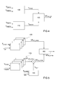
- the value of the speed V engine of the internal combustion engine 1 and the load L engine of the internal combustion engine 1 are transmitted in input to both a calculation block 100 and a block 110.
- Block 100 determines the maximum quantity T cold of fuel for each partial injection in the intake stroke INT in cold temperature conditions, i.e. at approximately 20°C, as a function of the speed V engine of the internal combustion engine 1 and of the load L engine of the internal combustion engine 1.
- a map is stored in the control unit 16, which map provides as result, as a function of the speed V engine of the internal combustion engine 1 and of the load L engine of the internal combustion engine 1, the maximum quantity T cold of fuel for each partial injection in the intake stroke INT in cold temperature conditions.
- Block 110 determines the maximum quantity T warm of fuel for each partial injection in the intake stroke INT in warm temperature conditions, i.e. at approximately 90°C, as a function of the speed V engine of the internal combustion engine 1 and of the load L engine of the internal combustion engine 1.
- a map is stored in the control unit 16, which map provides as result, as a function of the speed V engine of the internal combustion engine 1 and of the load L engine of the internal combustion engine 1, the maximum quantity T warm of fuel for each partial injection in the intake stroke INT in warm temperature conditions.
- both the cold temperature (approximately 20°C) and the warm temperature (approximately 90°C) is the temperature of the internal combustion engine 1 in cold temperature conditions and in the hot temperature conditions; the temperature of the internal combustion engine 1 may be approximated to the temperature T coolant of the cooling fluid of the internal combustion engine 1.
- the maximum quantity T warm of fuel for each partial injection in the intake stroke INT in warm temperature conditions and the maximum quantity T cold of fuel for each partial injection in the intake stroke INT in cold temperature conditions are transmitted in input to a calculation block 120 which determines the maximum quantity QF max_int of fuel for each partial injection in the intake stroke INT.
- the maximum quantity QF max_int of fuel for each partial injection in the intake stroke INT is calculated by means of a weighted mean of the maximum quantity T warm of fuel for each partial injection in the intake stroke INT in warm temperature conditions and of the maximum quantity T cold of fuel for each partial injection in the intake stroke INT in cold temperature conditions.
- the weights are represented by the distance of the current temperature T coolant of the cooling fluid of the internal combustion engine 1 from the reference temperatures, i.e.
- the weights of the maximum quantity T warm of fuel for each partial injection in the intake stroke INT in warm temperature conditions and of the maximum quantity T cold of fuel for each partial injection in cold temperature conditions in the intake stroke INT are established with linear dependence by the difference of the current temperature T coolant of the cooling fluid of the internal combustion engine 1 from the reference temperatures, i.e. from the cold temperature (approximately 20°C) and from the warm temperature (approximately 90°C).
- the contribution of the maximum quantity T cold of fuel for each partial injection in the intake stroke INT in cold temperature conditions is higher for current temperatures T coolant of the cooling fluid of the internal combustion engine 1 comprised in the 20°C - 55°C range; the contribution of the maximum quantity T warm of fuel for each partial injection in the intake stroke INT in warm temperature conditions is higher for current temperatures T coolant of the cooling fluid of the internal combustion engine 1 comprised in the 55°C - 90° range; and the two contributions weigh in the same manner for the current temperature T coolant of the cooling fluid of the internal combustion engine 1 equal to 55°C.
- the weights of the maximum quantity T warm of fuel for each partial injection in the intake stroke INT in warm temperature conditions and of the maximum quantity T cold of fuel for each partial injection in cold temperature conditions in the intake stroke INT are established with non-linear dependence by the difference of the current temperature T coolant of the cooling fluid of the internal combustion engine 1 from the reference temperatures, i.e. from the cold temperature (approximately 20°C) and from the warm temperature (approximately 90°C).
- control unit 16 is thus configured to determine, respectively, the weights of the maximum quantity T warm of fuel for each partial injection in the intake stroke INT in warm temperature conditions and of the maximum quantity T cold of fuel for each partial injection in cold temperature conditions so as to increase the contribution of the maximum quantity T warm of fuel for each partial injection in the intake stroke INT in warm temperature conditions.
- the control unit 16 is configured to proceed by trial and error to determine the number i of partial injections in the intake stroke INT until condition [1] occurs; the number i of partial injections in the intake stroke INT is comprised between one and a maximum value N max_int which is determined in a preliminary step of setting up and tuning.
- the objective quantity QF obj_int of fuel for each partial injection during the intake stroke INT is injected at regular intervals of time. In this manner, by keeping constant both the period of the partial injections and the objective quantity QF obj_int of fuel for each partial injection in the intake stroke INT, the conditions previous to the partial injection itself are substantially restored for each partial injection in the cylinder 2 (e.g. in terms of air resistance to the passage of fuel, turbulence inside the cylinder 2, etc.).
- the control unit 16 is thus configured to determine the period between two partial injections in the intake stoke INT as a function of the overall duration of the intake stroke INT, of the number of partial injections to be performed in the intake stroke INT and of the objective quantity QF obj_int of fuel to be injected for each partial injection in the intake stroke INT.
- the period between two partial injections in the intake stroke INT is thus variable as a function of the speed V engine of the internal combustion engine 1, of the load L engine of the internal combustion engine 1 and of the temperature T coolant of the cooling fluid of the internal combustion engine 1 and of the start of injection angle SOI.
- the effective quantity QF int of fuel for each partial injection in the intake stroke INT is not constant and is not even injected at regular intervals of time.
- the control unit 16 is configured to determine a partial injection pattern according to which the effective quantity QF int of fuel injected for each partial injection in the intake stroke INT gradually either increases or decreases and the period of time elapsing between two subsequent partial injections gradually increases. In this manner, by increasing both the period elapsing between two subsequent partial injections and reducing the effective quantity QF int of fuel for each partial injection during the intake stroke INT, the conditions previous to the partial injection itself in the cylinder 2 for each partial injection can be substantially restored.
- control unit 16 determines the number of partial injections, the quantity of fuel to be injected for each partial injection and the period between two subsequent partial injections during the compression stroke COMP is described below.
- the value of the end of injection angle EOI is determined and stored in the control unit 16.
- the value of the end of injection angle EOI is determined during a step of setting up and is kept constant; since, in the compression stroke COMP, the piston 3 is initially at bottom dead center PMI and rises to top dead center PMS, an error of the value of the end of injection angle EOI by a few degrees (i.e. if the injection ends too soon) could be very dangerous because the piston 3 may be already too close to the injector 14 and the injected fuel may therefore foul the crown of the piston 3 itself or the walls of the cylinder 2.
- a series of maps 130 are stored in control unit 16.
- the number of maps 130 stored in the control unit 16 is equal to the maximum number N max_comp of partial injections in the compression stroke COMP which is determined in a preliminary step of setting up and tuning.
- N max_comp the maximum number of partial injections in the compression stroke COMP which is determined in a preliminary step of setting up and tuning.
- four maps 130, which represent the maximum value of four partial injections in the compression stroke COMP, are stored in the control unit 16.
- Each map 130 provides the initial quantity QF init_comp of the fuel to be injected for a respective partial injection in the compression stroke COMP or a percentage with respect to the total fuel quantity to be injected in the compression stroke COMP, starting from which the aforesaid initial quantity QF mit_comp of the fuel to be injected for a respective partial injection in the compression stroke COMP can be determined.
- the initial quantity QF init_comp of fuel to be injected for a respective partial injection in the compression stroke COMP is determined as a function of two parameters.
- Such parameters are the temperature T coolant_start of the cooling fluid when the internal combustion engine 1 is started and the off time T off of the internal combustion engine 1 (i.e. the interval of time for which the internal combustion engine 1 remains off).
- Each map 130 thus provides, for the corresponding partial injection in the compression stroke COMP, the initial quantity QF init_comp of fuel to be injected as a function of the temperature T coolant_init of the cooling fluid when the internal combustion engine 1 is started and as a function of the off time T off of the internal combustion engine 1 (i.e. of the interval of time during which the internal combustion engine 1 remained off).
- a series of maps 140 are also stored in control unit 16.
- the number maps 140 stored in the control unit 16 is equal to the maximum number N max_comp of partial injections in the compression stroke COMP and which is determined in a preliminary step of setting up and tuning.
- four maps 140 which represent the maximum value of four partial injections in the compression stroke COMP, are stored in the control unit 16.
- Each map 140 provides the nominal quantity QF nom_comp of fuel to be injected for a respective partial injection in the compression stroke COMP or a percentage with respect to the total quantity of fuel to be injected in the compression stroke COMP, starting from which the aforesaid nominal quantity QF nom_comp of fuel to be injected for a respective partial injection in the compression stroke COMP can be determined.
- the nominal quantity QF nom_comp of fuel to be injected for a respective partial injection in the compression stroke COMP is determined as a function of two parameters. Such parameters are the speed V engine of the internal combustion engine 1 and the load L engine of the internal combustion engine 1.
- Each map 140 thus provides the nominal quantity QF nom_comp of fuel to be injected as a function of the speed V engine of the internal combustion engine 1 and of the load L engine of the internal combustion engine 1 for the corresponding partial injection, in the compression stroke COMP.
- the nominal quantity QF nom_comp of the fuel to be injected for a respective partial injection in the compression stroke COMP is corrected by means of a corrective contribution % corr for a respective partial injection in the compression stroke COMP.
- a map 150 which provides the corrective contribution % corr of fuel to be injected for a respective partial injection in the compression stroke COMP, is stored in the control unit 16.
- the corrective contribution % corr of fuel to be injected for a respective partial injection in the compression stroke COMP is determined as a function of two parameters. Such parameters are the temperature T coolant of the cooling fluid of the warm internal combustion engine 1 and the decay of the spark advance SA implemented by the internal combustion engine 1 with respect to the optimal spark advance (i.e. the spark advance which allows to generate the maximum torque).
- the map 150 thus provides, for the corresponding partial injection in the compression stroke COMP, the corrective contribution % corr of fuel to be injected as a function of the temperature T coolant of the cooling fluid of the internal combustion engine 1 and of the decay of the spark advance SA implemented by the internal combustion engine 1.
- the objective quantity QF obj_comp of fuel to be injected for a respective partial injection in the compression stroke COMP is determined by adding the nominal quantity QF nom_comp of the fuel to be injected for a respective partial injection in the compression stroke COMP and the corrective contribution % corr of fuel to be injected for a respective partial injection in the compression stroke COMP.
- the objective quantity QF obj_comp of fuel to be injected for a partial injection in the compression stroke COMP and the initial quantity QF init_comp of fuel to be injected for a partial injection in the compression stroke COMP are transmitted in input to a calculation block 160 which determines the effective quantity QF eff_comp of fuel to be injected for a specific partial injection in the compression stroke COMP.
- figure 6 shows a chart used for calculating the effective quantity QF eff_comp of fuel to be injected for a specific partial injection in the compression stroke COMP.
- a series of curves A, B, C, significant of the evolution over time of the effective quantity QF eff_comp of fuel to be injected for a specific partial injection in the compression stroke COMP, are stored in the control unit 16.
- the curve A, B, C is chosen as a function of the temperature T coolant_init of the cooling fluid when the internal combustion engine 1 is started; in other words, every curve A, B, C is indicative of the operation in the compression stroke COMP at a given temperature T coolant_init of the cooling fluid when the internal combustion engine 1 is started.
- the number of partial injections in the compression stroke COMP to be taken into consideration is comprised between zero and a maximum number TDC max of partial injections in the compression stroke COMP.
- the equation [3] is verified for each partial injection in the compression stroke COMP (comprised between zero and a maximum number TDC max of partial injections in the compression stroke COMP).
- the effective quantity QF eff_comp of fuel to be injected for a specific partial injection in the compression stroke COMP will substantially coincide with the initial quantity QF init_comp of fuel to be injected for a specific partial injection in the compression stroke COMP and will evolve so that, at the maximum number TDC max of partial injections in the compression stroke COMP, the effective quantity QF eff_comp of fuel to be injected for a specific partial injection in the compression stroke COMP substantially coincides with the objective quantity QF obj_comp of fuel to be injected for a partial injection in the compression stroke COMP.
- control unit is configured to make a weighted mean of the objective quantity QF obj_comp_TDC of fuel to be injected for a specific partial injection in the compression stroke COMP and of the initial quantity QF init_comp_TDC of fuel to be injected in the compression stroke COMP to establish the effective quantity QF eff_comp_TDC of fuel to be injected for a specific partial injection in the compression stroke COMP; in which the weight ⁇ A , ⁇ B , ⁇ C of the objective quantity QF obj_comp_TDC of fuel to be injected for a specific partial injection in the compression stroke COMP is determined by means of the respective curve A, B, C shown in the chart in figure 6 and the weight of the initial quantity QF init_comp_TDC to be injected for a specific partial injection in the compression stroke COMP is calculated as the completion to 1 of the respective weight ⁇ A , ⁇ B , ⁇ C of the objective quantity QF obj_comp_TDC of fuel to be injected for a specific partial partial injection in the
- the chart shown in figure 7 is constructed so as to provide the weight ⁇ (comprised between 0 and 1) to be attributed to the initial quantity QF init_comp_TDC of fuel to be injected for a specific partial injection in the compression stroke COMP.
- map 130 according to which the initial quantity QF init_comp of fuel to be injected for a respective partial injection in the compression stroke COMP is determined
- map 140 according to which the nominal quantity QF nom_comp of fuel to be injected for a respective partial injection in the compression stroke COMP is determined
- the effective quantity QF eff_comp_TDC of fuel to be injected may be zero.
- the number of partial injections in the compression stroke COMP is lower than the maximum number N max_comp of partial injections in the compression stroke COMP which is determined in a preliminary step of setting up and tuning.
- the number of partial injections in the compression stroke COMP may be any number from 0 to 4, which is equal to maximum number N max_comp of partial injections in the compression stroke COMP.
- an objective pattern of partial injections to be implemented in the compression stroke COMP for each four-stroke combustion cycle of each cylinder 2 can be determined as a function of the request of torque C to be delivered.
- the control unit 16 is thus configured to determine the period between two partial injections in the compression stroke COMP.
- the control unit 16 is provided so that an interval of time elapses between two subsequent partial injections j, j+1 in the compression stroke COMP, which interval of time is variable as a function of the effective quantity QF eff_comp of fuel injected in the partial injection j which allows to restore substantially the conditions previous to the partial injection j itself in the cylinder 2 (e.g. in terms of air resistance to the passage of fuel, turbulence in the cylinder 2, etc.).
- the period between two partial injections in the compression stroke COMP is variable as a function of the speed V engine of the internal combustion engine 1, of the load L engine of the internal combustion engine 1 and of the temperature T coolant of the cooling fluid of the internal combustion engine 1 and, possibly, of the end of injection angle EOI.
- the control unit 16 is further configured to determine the minimum quantity QF min_comp of fuel to be injected for each partial injection in the compression stroke COMP; such a minimum quantity QF min_comp of fuel to be injected for each partial injection in the compression stroke COMP is variable as a function of the feeding pressure upstream of the injector 14 and represents the quantity for which the injector 14 can guarantee the injections in repeatable and controlled manner.
- the effective pattern of partial injections to be performed in the compression stroke COMP can be determined as a function of the objective pattern of partial injections to be performed during the compression stroke COMP for each combustion cycle of each cylinder 2 and the minimum quantity QF min_comp to be injected for each partial injection in the compression stroke COMP.
- the objective pattern of partial injections to be performed in the compression stroke COMP will coincide with the actual pattern of partial injections to be implemented in the compression stroke COMP.
- the objective pattern of partial injections to be performed in the compression stroke COMP includes three partial injections; in which the effective quantity Q 1 of fuel to be injected in the first partial injection is higher than the minimum quantity QF min_comp of fuel to be injected for each partial injection in the compression stroke COMP, while the effective quantity Q 2 of fuel to be injected in the second partial injection and the effective quantity Q 3 of fuel to be injected in the third partial injection are lower than the minimum quantity QF min_comp of fuel to be injected for each partial injection in the compression stroke COMP and the sum of the effective quantity Q 2 of fuel to be injected in the second partial injection and of the effective quantity Q 3 of fuel to be injected in the third partial injection is higher than the minimum quantity QF min_comp of fuel to be injected for each partial injection in the compression stroke COMP.
- the effective pattern of partial injections to be performed in the compression stroke COMP includes two partial injections; in which the effective quantity Q' 1 of fuel to be injected in the first partial injection is equal to the first effective quantity Q 1 of fuel to be injected in the first partial injection and the effective quantity Q' 2 of fuel to be injected in the second partial injection is equal to the sum of the effective quantity Q 2 of fuel to be injected in the second partial injection of the objective pattern and of the effective quantity Q 3 of fuel to be injected in the third partial injection of the objective pattern.
- the end of injection angle EOI, the quantity Q fuel_comp of fuel injected as a whole in the compression stroke COMP and the interval of time elapsing between the first partial injection Q 1 , Q' 1 and the second partial injection Q 2 , Q' 2 can be kept unchanged in the effective pattern of partial injections.
- the objective pattern of partial injections to be performed in the compression stroke COMP includes three partial injections; in which both the effective quantity Q 1 of fuel to be injected in the first partial injection and the effective quantity Q 2 of fuel to be injected in the second partial injection are lower than the minimum quantity QF min_comp of fuel to be injected for each partial injection in the compression stroke COMP and the sum of the effective quantity Q 1 of fuel to be injected in the first partial injection and of the effective quantity Q 2 of fuel to be injected in the second partial injection is higher than the minimum quantity QF min_comp of fuel to be injected for each partial injection in the compression stroke COMP.
- the effective pattern of partial injections to be performed in the compression stroke COMP includes only one injection; wherein the effective quantity Q' 1 of fuel to be injected in the first injection is equal to the effective quantity Q 1 of fuel to be injected in the first objective pattern and to the effective quantity of fuel Q 2 to be injected in the second partial injection of the objective pattern.
- the objective pattern of partial injections to be performed in the compression stroke COMP includes two partial injections; in which both the effective quantity Q 1 of fuel to be injected in the first partial injection and the effective quantity Q 2 of fuel to be injected in the second partial injection are lower than the minimum quantity QF min_comp of fuel to be injected for each partial injection in the compression stroke COMP and the sum of the effective quantity Q 1 of fuel to be injected in the first partial injection and of the effective quantity Q 2 of fuel to be injected in the second partial injection is lower than the minimum quantity QF min_comp of fuel to be injected for each partial injection in the compression stroke COMP.
- the actual pattern of partial injections to be performed in the compression stroke COMP does not include any injection; the sum of the effective quantity Q 1 of fuel to be injected in the first partial injection of the objective pattern and of the effective quantity Q 2 of fuel to be injected in the second partial injection of the objective pattern is injected in the intake stroke INT.
- the quantity Q fuel of fuel injected as a whole in the combustion cycle can be kept unchanged.
- the objective pattern of partial injections to be performed in the compression stroke COMP includes three partial injections; in which both the effective quantity Q 1 of fuel to be injected in the first partial injection and the effective quantity Q 2 of fuel to be injected in the second partial injection are lower than the minimum quantity QF min_comp of fuel to be injected for each partial injection in the compression stroke COMP, while the effective quantity Q 3 of fuel to be injected in the third partial injection is higher than the minimum quantity QF min_comp of fuel to be injected for each partial injection in the compression stroke COMP and the sum of the effective quantity Q 1 to be injected in the first partial injection and of the effective quantity Q 2 of fuel to be injected in the second partial injection is higher than the minimum quantity QF min_comp of fuel to be injected for each partial injection in the compression stroke COMP.
- the effective pattern of partial injections to be performed in the compression stroke COMP includes two partial injections; in which the effective quantity Q' 1 of fuel to be injected in the first injection is equal to the sum of the effective quantity Q 1 of fuel to be injected in the first partial injection and the effective quantity Q 2 of fuel to be injected in the second partial injection of the objective pattern and the effective quantity Q' 2 of fuel to be injected in the second injection is equal to the effective quantity Q 3 of fuel to be injected in the third partial injection of the objective pattern.
- both the end of injection angle EOI and the quantity Q fuel_comp of fuel injected as a whole in the compression stroke COMP can be kept unchanged in the effective pattern of partial injections.
- control unit 16 is configured to determine the overall quantity Q fuel of fuel to be injected for each four-stroke combustion cycle of each cylinder 2 as a function of the request for torque C to be delivered which determines the quantity of air which must be aspirated by the engine. Having determined the overall quantity Q fuel of fuel to be injected for each four-stroke combustion cycle of each cylinder 2, the control unit 16 is configured to determine the effective pattern of partial injections to be performed during the compression stroke COMP according to the previous description.
- the quantity Q fuel_int of fuel to be injected for each four-stroke combustion cycle of each cylinder 2 in the intake stroke INT is then calculated by means of the difference between the overall quantity Q fuel to be injected for each four-stroke combustion cycle of each cylinder 2 and the quantity Q fuel_comp of fuel to be injected for each four-stroke combustion cycle of each cylinder 2 in the compression stroke COMP.
- a quantity Q fuel_esp of fuel can be injected in the expansion stroke ESP as a function of the decay of the spark advance SA performed by the internal combustion engine 1; in particular, a quantity Q fuel_esp of fuel can be substantially injected in the instance in which the spark plug is controlled to produce a spark.
- the strategy implemented by the control unit 16 to determine the number of partial injections, the quantity of fuel to be injected for each partial injection and the period between two subsequent partial injections during the compression stroke COMP and the strategy implemented by the control unit 16 to determine the number of partial injections, the quantity of fuel to be injected for each partial injection and the period between two subsequent partial injections during the intake stroke INT are completely and mutually independent.
- the strategies implemented by the control unit 16 described hereto have many advantages. Firstly, the strategies described above are applied in individual manner to each cylinder 2; in this manner, it is possible to take into account the inevitable differences which exist between the various cylinders 2 by effect of manufacturing tolerances and by effect of the difference of temperature of the walls of the cylinders 2 due to the different positions of the cylinders 2 in the internal combustion engine 1. Secondly, the strategies described above are simple and cost-effective to implement in a control unit 16 of an internal combustion engine 1 because they do not require any physical change, employ a moderate calculating capacity of the control unit 6 and at the same time allow to optimize the thermodynamics of the combustion with evident benefits on consumptions and containment of polluting emissions.
Landscapes
- Engineering & Computer Science (AREA)
- Chemical & Material Sciences (AREA)
- Combustion & Propulsion (AREA)
- Mechanical Engineering (AREA)
- General Engineering & Computer Science (AREA)
- Electrical Control Of Air Or Fuel Supplied To Internal-Combustion Engine (AREA)
- Combined Controls Of Internal Combustion Engines (AREA)
Abstract
Description
- The present invention relates to a method to determine the injection pattern in the compression stroke of the combustion cycle of the cylinders of a direct-injection internal combustion engine.
- A spark-ignited, direct-injection internal combustion engine comprises a number of cylinders, each of which is provided with a respective piston, which cyclically slides within the cylinder and is mechanically connected by means of a connecting rod to a crankshaft to transmit to the drive shaft itself the force generated by the combustion within the cylinder, with a respective injector partially arranged inside the cylinder and with a respective spark plug, which is cyclically controlled by an electronic control unit to produce a spark between its electrodes and thus determine the ignition of the compressed gases in the cylinder itself. The internal combustion engine further comprises an intake manifold, which is connected to each cylinder by means of one or more intake valves, and an exhaust manifold, which is connected to each cylinder by means of one or more exhaust valves and which leads to an emission pipe to emit the gases produced by the combustion into the atmosphere.
- The four-stroke combustion cycle of each cylinder consists of four strokes in sequence: an intake stroke, a compression stroke, an expansion stroke and an exhaust stroke. At the end of each combustion cycle, two complete revolutions will have been completed by the drive shaft, thus covering a rotation equal to 720°. The piston is initially at top dead center and, during the intake stroke, descends to bottom dead center by generating a vacuum in the cylinder which, as the respective intake valve opens, recalls air from the intake pipe covering half a revolution of the drive shaft and exploring an angle from 0° to 180°. Fuel is injected in the combustion chamber during the intake stroke and/or during the subsequent compression stroke. During the subsequent compression stroke, the piston rises from bottom dead center to top dead center, thus compressing the air and fuel mixture which is in the cylinder, causing an increase of pressure and of temperature, covering half a revolution of the drive shaft and exploring an angle from 180° to 360°.
- During the expansion stroke, the electrodes of the spark plug produce the spark which ignites the air and fuel mixture in the cylinder starting the combustion itself, which produces an increase of temperature and pressure in addition to being the only step of the combustion cycle in which useful work is generated. The piston is pushed from top dead center to bottom dead center by covering half a revolution of the drive shaft and exploring an angle from 360° to 540°. Finally, in the exhaust stroke, the piston is at bottom dead center again and moves up to top dead center to eject the burnt gases, which are introduced into the exhaust pipe, by means of the respective exhaust valve, covering half a revolution of the drive shaft and exploring an angle from 540° to 720°.
- The overall quantity of fuel to be injected for each four-stroke combustion cycle can be determined as a function of the torque to be delivered to the drive wheels which determines the quantity of air that the engine must aspirate. The overall quantity of fuel to be injected for each four-stroke combustion cycle of each cylinder may be injected, alternatively, either during the intake stroke, or during the compression stroke, or even during both the intake stroke and the compression stroke.
- The definition of the injection pattern (i.e. the determination of the stroke or strokes of the combustion cycle during which the quantity of fuel is either completely or partially injected) is extremely critical to be able guarantee a correct mixing of air and fuel and to prevent the fuel from fouling the crown of the piston or the walls of the cylinder and causing the formation of particulate.
- It is the object of the present invention to provide a method to determine the injection pattern in the compression stroke of the combustion cycle of the cylinders of a direct-injection internal combustion engine, which method is free from the drawbacks described above and which, in particular, is easy and cost-effective to implement.
- It is a further object of the present invention to provide a control unit suited to determine the injection pattern in the combustion stroke of the combustion cycle of the cylinders of a direct-injection internal combustion engine, which is free from the drawbacks of the prior art.
- According to the present invention, a control unit and a method for determining the injection pattern in the combustion stroke of the combustion cycle of the cylinders of a direct-injection internal combustion engine are provided as disclosed in the appended claims.
- The present invention will now be described with reference to the accompanying drawings, which show a non-limiting embodiment thereof, in which:
-
figure 1 is diagrammatic view of a direct-injection internal combustion engine provided with a control unit which implements the method to determine the injection pattern in the intake/compression strokes object of the present invention; -
figure 2 is a diagrammatic view of a cylinder of the internal combustion engine infigure 1 ; and -
figure 3 diagrammatically shows the various strokes of a combustion cycle in the cylinder infigure 2 in sequence; -
figure 4 is a block chart of the method to determine the injection pattern in the intake stroke object of the present invention; -
figure 5 is a block chart of the method to determine the injection pattern in the compression stroke object of the present invention; -
figure 6 is a chart used in the method infigure 5 to determine the injection pattern in the compression stroke; and - figures from 7 a) to 7 d) show the comparison between some partial injection patterns to be implemented in the compression stroke obtained by means of the method in
figure 5 . - In
figure 1 ,reference numeral 1 indicates as a whole a spark-ignited internal combustion engine comprising fourcylinders 2 in a straight arrangement. Eachcylinder 2 comprises arespective piston 3 mechanically connected by means of a connecting rod to acrankshaft 4 for transmitting the force generated by the combustion in thecylinder 2 to thedrive shaft 4 itself. - As shown in
figure 2 , theinternal combustion engine 1 comprises anintake manifold 5, which is connected to eachcylinder 2 by means of two intake valves 6 (of which only one is shown infigure 2 ) and receives fresh air (i.e. air from the outside environment) through a butterfly valve 7 moveable between a closing position and a maximum opening position. Furthermore, theinternal combustion engine 1 comprises anexhaust manifold 8, which is connected to eachcylinder 2 by means of two exhaust valves 9 (only one of which is shown infigure 2 ) which leads into an emission pipe (not shown) to emit the gases produced by the combustion into the atmosphere. - The position of each exhaust valve 9 is directly controlled by a
camshaft 10 which receives motion from thedrive shaft 4; instead, the position of theintake valves 6 may be controlled by a generic valveopening control device 11 which controls theintake valves 6 managing the opening and lift angle so as to control the torque delivered by means of theintake valves 6. The valveopening control device 11 uses atraditional camshaft 12 which receives motion from thedrive shaft 4 and for eachintake valve 6 may comprise an electrically controlled hydraulic actuator 13 (i.e. controlled by means of a solenoid valve), which is interposed between a stem of theintake valve 6 and thecamshaft 12. By appropriately controlling eachhydraulic actuator 13, it is possible to adjust the motion transmitted by thecamshaft 12 to theintake valve stem 6, and it is thus possible to adjust the actual lift of theintake valve 6. Thus, the action of thecontrol device 11 may allow to vary the actual lift of eachintake valve 6 independently from theother intake valves 6, for eachcylinder 2 and engine cycle. - A
corresponding injector 14 is provided for eachcylinder 2; according to the embodiment shown infigure 2 , the injection is of the direct type and therefore eachinjector 14 is partially arranged inside thecylinder 2. According to an alternative embodiment (not shown), and limitedly to the application of the part concerning the intake valve INT of the present invention only, the injection is of the indirect type, and therefore eachinjector 14 is arranged upstream of thecylinder 2 in an intake pipe which connects theintake manifold 5 to thecylinder 2. - Furthermore, each
cylinder 2 comprises aspark plug 15, which is arranged through the top of thecylinder 2 in central position between theintake valves 5 and the exhaust valves 9 and is cyclically activated to determine the ignition of the compressed gases in thecylinder 2 at the end of each compression stroke. - The
engine 1 comprises acontrol unit 16, which governs the operation of theinternal combustion engine 1 and, among other things, controls thespark plugs 15 to determine the ignition of the compressed gases in eachcylinder 2. Thecontrol unit 16 comprises amemory 17, in which a series of maps, which provide the control values of thespark plugs 15 as a function of the current engine point, are stored; in particular, the maps stored in thememory 17 provide a standard spark advance for each spark plug 15 (i.e. for each cylinder 2). -
Figure 3 shows the four-stroke combustion cycle of eachcylinder 2. The complete combustion cycle is implemented by the sequence of four strokes: an intake stroke INT, a compression stroke COMP, an expansion stroke ESP and an exhaust stroke EXH. At the end of each combustion cycle two complete revolutions will have been completed by thedrive shaft 4, thus covering a rotation equal to 720°. - During the intake stroke INT, the
piston 3 is initially at top dead center PMS and descends to bottom dead center PMI generating a vacuum in thecylinder 2, which vacuum, as therespective intake valve 6 opens, recalls air from theintake manifold 5 covering half a revolution of thedrive shaft 4 and exploring an angle from 0° to 180°. - Fuel is injected into the combustion chamber during the described intake stroke ASP and/or the subsequent compression stroke COMP.
- In the compression stroke COMP, the
piston 3 rises from bottom dead center PMI to top dead center PMS, thus compressing the air and fuel mixture which is in thecylinder 2 and causing an increase of pressure and of temperature, covering half a revolution of the drive shaft 4 (so as to complete the first complete revolution of the drive shaft 4) and exploring an angle from 180° to 360°. - During the expansion stroke ESP, the electrodes of the
spark plug 15 cause a spark which ignites the air and fuel mixture in thecylinder 2 starting the combustion itself, which produces an increase of temperature and pressure in addition to being the only step of the combustion cycle in which useful work is generated. Thepiston 3 is pushed from top dead center PMS to bottom dead center PMI by covering half a revolution of thedrive shaft 4 and exploring an angle from 360° to 540°. - In the exhaust stroke EXH, the
piston 3 is at bottom dead center PMI again and moves up to top dead center PMS to eject the burnt gases, which are introduced into the exhaust pipe, by means of the respective exhaust valve 9, covering half a revolution of the drive shaft 4 (so as to complete the second complete revolution of the drive shaft 4) and exploring an angle from 540° to 720°. - The strategy implemented by the
control unit 16 to determine the number of partial injections, the quantity of fuel to be injected for each partial injection and the period between two subsequent partial injections during the intake stroke INT is described below. - The
control unit 16 is configured to determine the overall quantity Qfuel of fuel to be injected for each combustion cycle of eachcylinder 2 as a function of the request for torque C to be delivered to the drive wheels which determines the quantity of air that theinternal combustion engine 1 must aspirate. Having determined the overall quantity of fuel Qfuel to be injected for each combustion cycle of eachcylinder 2, thecontrol unit 16 is configured to determine, respectively, the quantity of fuel Qfuel_int to be injected for each combustion cycle of eachcylinder 2 during the intake stroke INT, the quantity Qfuel_comp of fuel to be injected for each combustion cycle of eachcylinder 2 during the compression stroke COMP and, possibly, also the quantity Qfuel_esp of fuel to be injected for each combustion cycle of eachcylinder 2 during the expansion stroke ESP. In other words, according to alternative embodiments, the overall quantity Qfuel of fuel to be injected for each combustion cycle of eachcylinder 2 is divided into a contribution injected in the intake stroke INT and/or a contribution injected in the compression stroke COMP and/or a contribution injected in the expansion stroke ESP. - During a preliminary step, the value of the start of injection angle SOI is determined and stored in the
control unit 16. According to a preferred variant, the value of the start of injection angle SOI is determined during a step of setting up and is kept constant; as thepiston 3 is initially at top dead center PMS and descends to bottom dead center PMI in the intake stroke INT, an error of the value of the start of injection angle SOI by a few degrees (i.e. if the injection starts too soon) could be very dangerous because thepiston 3 may still be too close to theinjector 14 and the injected fuel may therefore foul the crown of thepiston 3 itself or the walls of thecylinder 2. - As shown in
figure 4 , thecontrol unit 16 is thus configured to determine the maximum quantity Tcold of fuel for each partial injection during the intake stroke INT in cold temperature conditions and the maximum quantity Twarm of fuel for each partial injection in the intake stroke INT in warm temperature conditions. In more detail, the value of the speed Vengine of theinternal combustion engine 1 and the load Lengine of theinternal combustion engine 1 are transmitted in input to both acalculation block 100 and ablock 110. -
Block 100 determines the maximum quantity Tcold of fuel for each partial injection in the intake stroke INT in cold temperature conditions, i.e. at approximately 20°C, as a function of the speed Vengine of theinternal combustion engine 1 and of the load Lengine of theinternal combustion engine 1. In substance, a map is stored in thecontrol unit 16, which map provides as result, as a function of the speed Vengine of theinternal combustion engine 1 and of the load Lengine of theinternal combustion engine 1, the maximum quantity Tcold of fuel for each partial injection in the intake stroke INT in cold temperature conditions. -
Block 110 determines the maximum quantity Twarm of fuel for each partial injection in the intake stroke INT in warm temperature conditions, i.e. at approximately 90°C, as a function of the speed Vengine of theinternal combustion engine 1 and of the load Lengine of theinternal combustion engine 1. In substance, a map is stored in thecontrol unit 16, which map provides as result, as a function of the speed Vengine of theinternal combustion engine 1 and of the load Lengine of theinternal combustion engine 1, the maximum quantity Twarm of fuel for each partial injection in the intake stroke INT in warm temperature conditions. - It is worth noting that both the cold temperature (approximately 20°C) and the warm temperature (approximately 90°C) is the temperature of the
internal combustion engine 1 in cold temperature conditions and in the hot temperature conditions; the temperature of theinternal combustion engine 1 may be approximated to the temperature Tcoolant of the cooling fluid of theinternal combustion engine 1. - The maximum quantity Twarm of fuel for each partial injection in the intake stroke INT in warm temperature conditions and the maximum quantity Tcold of fuel for each partial injection in the intake stroke INT in cold temperature conditions are transmitted in input to a
calculation block 120 which determines the maximum quantity QFmax_int of fuel for each partial injection in the intake stroke INT. The maximum quantity QFmax_int of fuel for each partial injection in the intake stroke INT is calculated by means of a weighted mean of the maximum quantity Twarm of fuel for each partial injection in the intake stroke INT in warm temperature conditions and of the maximum quantity Tcold of fuel for each partial injection in the intake stroke INT in cold temperature conditions. The weights are represented by the distance of the current temperature Tcoolant of the cooling fluid of theinternal combustion engine 1 from the reference temperatures, i.e. from the cold temperature (approximately 20°C) and from the hot temperature (approximately 90°C). According to a preferred embodiment, the weights of the maximum quantity Twarm of fuel for each partial injection in the intake stroke INT in warm temperature conditions and of the maximum quantity Tcold of fuel for each partial injection in cold temperature conditions in the intake stroke INT are established with linear dependence by the difference of the current temperature Tcoolant of the cooling fluid of theinternal combustion engine 1 from the reference temperatures, i.e. from the cold temperature (approximately 20°C) and from the warm temperature (approximately 90°C). In other words, the contribution of the maximum quantity Tcold of fuel for each partial injection in the intake stroke INT in cold temperature conditions is higher for current temperatures Tcoolant of the cooling fluid of theinternal combustion engine 1 comprised in the 20°C - 55°C range; the contribution of the maximum quantity Twarm of fuel for each partial injection in the intake stroke INT in warm temperature conditions is higher for current temperatures Tcoolant of the cooling fluid of theinternal combustion engine 1 comprised in the 55°C - 90° range; and the two contributions weigh in the same manner for the current temperature Tcoolant of the cooling fluid of theinternal combustion engine 1 equal to 55°C. - According to a further embodiment, the weights of the maximum quantity Twarm of fuel for each partial injection in the intake stroke INT in warm temperature conditions and of the maximum quantity Tcold of fuel for each partial injection in cold temperature conditions in the intake stroke INT are established with non-linear dependence by the difference of the current temperature Tcoolant of the cooling fluid of the
internal combustion engine 1 from the reference temperatures, i.e. from the cold temperature (approximately 20°C) and from the warm temperature (approximately 90°C). In this case, thecontrol unit 16 is thus configured to determine, respectively, the weights of the maximum quantity Twarm of fuel for each partial injection in the intake stroke INT in warm temperature conditions and of the maximum quantity Tcold of fuel for each partial injection in cold temperature conditions so as to increase the contribution of the maximum quantity Twarm of fuel for each partial injection in the intake stroke INT in warm temperature conditions. - The
control unit 16 is thus configured to determine the number of partial injections in the intake stroke INT by means of the following ratio:
Qfuel_int quantity of fuel to be injected for each four-stroke combustion cycle of eachcylinder 2 in the intake stroke INT;
QFmax_int maximum quantity of fuel for each partial injection in the intake stroke INT; and
number of partial injections to be performed in the intake stroke INT. - The
control unit 16 is configured to proceed by trial and error to determine the number i of partial injections in the intake stroke INT until condition [1] occurs; the number i of partial injections in the intake stroke INT is comprised between one and a maximum value Nmax_int which is determined in a preliminary step of setting up and tuning. - According to a preferred variant, once the number i of partial injections to be performed in the intake stroke INT is determined, the quantity QFobj_int of fuel injected for each partial injection in the intake stroke INT is constant and equal, for each partial injection, to:

Qfuel_int quantity of fuel to be injected for each four-stroke combustion cycle of eachcylinder 2 in the intake stroke INT;
QFobj_int objective quantity of fuel for each partial injection in the intake stroke INT; and
i number of partial injections to be performed in the intake stroke INT. - According to a preferred variant, the objective quantity QFobj_int of fuel for each partial injection during the intake stroke INT is injected at regular intervals of time. In this manner, by keeping constant both the period of the partial injections and the objective quantity QFobj_int of fuel for each partial injection in the intake stroke INT, the conditions previous to the partial injection itself are substantially restored for each partial injection in the cylinder 2 (e.g. in terms of air resistance to the passage of fuel, turbulence inside the
cylinder 2, etc.). - The
control unit 16 is thus configured to determine the period between two partial injections in the intake stoke INT as a function of the overall duration of the intake stroke INT, of the number of partial injections to be performed in the intake stroke INT and of the objective quantity QFobj_int of fuel to be injected for each partial injection in the intake stroke INT. The period between two partial injections in the intake stroke INT is thus variable as a function of the speed Vengine of theinternal combustion engine 1, of the load Lengine of theinternal combustion engine 1 and of the temperature Tcoolant of the cooling fluid of theinternal combustion engine 1 and of the start of injection angle SOI. - According to a further variant, the effective quantity QFint of fuel for each partial injection in the intake stroke INT is not constant and is not even injected at regular intervals of time. In particular, the
control unit 16 is configured to determine a partial injection pattern according to which the effective quantity QFint of fuel injected for each partial injection in the intake stroke INT gradually either increases or decreases and the period of time elapsing between two subsequent partial injections gradually increases. In this manner, by increasing both the period elapsing between two subsequent partial injections and reducing the effective quantity QFint of fuel for each partial injection during the intake stroke INT, the conditions previous to the partial injection itself in thecylinder 2 for each partial injection can be substantially restored. - The choice of increasing or decreasing the effective quantity QFint of fuel injected for each partial injection in the intake stroke INT depends on the following two (mutually disagreeing) needs for which an optimization trade-off must be found in the various operating conditions of the internal combustion engine 1:
- since in the intake stroke INT the
piston 3 descends from top dead center PMS to bottom dead center PMI and thus the distance of thepiston 3 from theinjector 14 decreases, it is possible to prevent the fuel from colliding against the crown of thepiston 3 itself even by increasing the effective quantity QFint of fuel for each partial injection; - as the mixture in the
cylinder 2 becomes rich in fuel, the penetration resistance of the jet of mixture decreases, and therefore the quantity of fuel in each single injection must be reduced. - The strategy implemented by the
control unit 16 to determine the number of partial injections, the quantity of fuel to be injected for each partial injection and the period between two subsequent partial injections during the compression stroke COMP is described below. - During a preliminary step, the value of the end of injection angle EOI is determined and stored in the
control unit 16. According to a preferred variant, the value of the end of injection angle EOI is determined during a step of setting up and is kept constant; since, in the compression stroke COMP, thepiston 3 is initially at bottom dead center PMI and rises to top dead center PMS, an error of the value of the end of injection angle EOI by a few degrees (i.e. if the injection ends too soon) could be very dangerous because thepiston 3 may be already too close to theinjector 14 and the injected fuel may therefore foul the crown of thepiston 3 itself or the walls of thecylinder 2. - As shown in
figure 5 , a series ofmaps 130 are stored incontrol unit 16. The number ofmaps 130 stored in thecontrol unit 16 is equal to the maximum number Nmax_comp of partial injections in the compression stroke COMP which is determined in a preliminary step of setting up and tuning. As shown infigure 5 , fourmaps 130, which represent the maximum value of four partial injections in the compression stroke COMP, are stored in thecontrol unit 16. - Each
map 130 provides the initial quantity QFinit_comp of the fuel to be injected for a respective partial injection in the compression stroke COMP or a percentage with respect to the total fuel quantity to be injected in the compression stroke COMP, starting from which the aforesaid initial quantity QFmit_comp of the fuel to be injected for a respective partial injection in the compression stroke COMP can be determined. - The initial quantity QFinit_comp of fuel to be injected for a respective partial injection in the compression stroke COMP is determined as a function of two parameters. Such parameters are the temperature Tcoolant_start of the cooling fluid when the
internal combustion engine 1 is started and the off time Toff of the internal combustion engine 1 (i.e. the interval of time for which theinternal combustion engine 1 remains off). - Each
map 130 thus provides, for the corresponding partial injection in the compression stroke COMP, the initial quantity QFinit_comp of fuel to be injected as a function of the temperature Tcoolant_init of the cooling fluid when theinternal combustion engine 1 is started and as a function of the off time Toff of the internal combustion engine 1 (i.e. of the interval of time during which theinternal combustion engine 1 remained off). - Again as shown in
figure 5 , a series ofmaps 140 are also stored incontrol unit 16. The number maps 140 stored in thecontrol unit 16 is equal to the maximum number Nmax_comp of partial injections in the compression stroke COMP and which is determined in a preliminary step of setting up and tuning. As shown infigure 5 , fourmaps 140, which represent the maximum value of four partial injections in the compression stroke COMP, are stored in thecontrol unit 16. - Each
map 140 provides the nominal quantity QFnom_comp of fuel to be injected for a respective partial injection in the compression stroke COMP or a percentage with respect to the total quantity of fuel to be injected in the compression stroke COMP, starting from which the aforesaid nominal quantity QFnom_comp of fuel to be injected for a respective partial injection in the compression stroke COMP can be determined. - The nominal quantity QFnom_comp of fuel to be injected for a respective partial injection in the compression stroke COMP is determined as a function of two parameters. Such parameters are the speed Vengine of the
internal combustion engine 1 and the load Lengine of theinternal combustion engine 1. - Each
map 140 thus provides the nominal quantity QFnom_comp of fuel to be injected as a function of the speed Vengine of theinternal combustion engine 1 and of the load Lengine of theinternal combustion engine 1 for the corresponding partial injection, in the compression stroke COMP. - According to a preferred variant, the nominal quantity QFnom_comp of the fuel to be injected for a respective partial injection in the compression stroke COMP thus determined is corrected by means of a corrective contribution %corr for a respective partial injection in the compression stroke COMP. In particular, a
map 150, which provides the corrective contribution %corr of fuel to be injected for a respective partial injection in the compression stroke COMP, is stored in thecontrol unit 16. The corrective contribution %corr of fuel to be injected for a respective partial injection in the compression stroke COMP is determined as a function of two parameters. Such parameters are the temperature Tcoolant of the cooling fluid of the warminternal combustion engine 1 and the decay of the spark advance SA implemented by theinternal combustion engine 1 with respect to the optimal spark advance (i.e. the spark advance which allows to generate the maximum torque). - The
map 150 thus provides, for the corresponding partial injection in the compression stroke COMP, the corrective contribution %corr of fuel to be injected as a function of the temperature Tcoolant of the cooling fluid of theinternal combustion engine 1 and of the decay of the spark advance SA implemented by theinternal combustion engine 1. - The objective quantity QFobj_comp of fuel to be injected for a respective partial injection in the compression stroke COMP is determined by adding the nominal quantity QFnom_comp of the fuel to be injected for a respective partial injection in the compression stroke COMP and the corrective contribution %corr of fuel to be injected for a respective partial injection in the compression stroke COMP.
- The objective quantity QFobj_comp of fuel to be injected for a partial injection in the compression stroke COMP and the initial quantity QFinit_comp of fuel to be injected for a partial injection in the compression stroke COMP are transmitted in input to a
calculation block 160 which determines the effective quantity QFeff_comp of fuel to be injected for a specific partial injection in the compression stroke COMP. - In particular,
figure 6 shows a chart used for calculating the effective quantity QFeff_comp of fuel to be injected for a specific partial injection in the compression stroke COMP. - A series of curves A, B, C, significant of the evolution over time of the effective quantity QFeff_comp of fuel to be injected for a specific partial injection in the compression stroke COMP, are stored in the
control unit 16. The curve A, B, C is chosen as a function of the temperature Tcoolant_init of the cooling fluid when theinternal combustion engine 1 is started; in other words, every curve A, B, C is indicative of the operation in the compression stroke COMP at a given temperature Tcoolant_init of the cooling fluid when theinternal combustion engine 1 is started. - The
control unit 16 is suited to determine the effective quantity QFeff_comp of the fuel to be injected for a specific partial injection in the compression stroke COMP by means of the following formula:
QFeff_comp_TDC effective quantity of fuel to be injected for a specific partial injection in the compression stroke COMP;
QFobj_comp_TDC objective quantity of fuel to be injected for a specific partial injection in the compression stroke COMP;
QFinit_comp_TDC initial quantity of fuel to be injected for a specific partial injection in the compression stroke COMP; and
α weight comprised between 0 and 1 to be assigned to the objective quantity of fuel to be injected for a specific partial injection in the compression stroke COMP. - The number of partial injections in the compression stroke COMP to be taken into consideration is comprised between zero and a maximum number TDCmax of partial injections in the compression stroke COMP. The equation [3] is verified for each partial injection in the compression stroke COMP (comprised between zero and a maximum number TDCmax of partial injections in the compression stroke COMP).
- Initially, the effective quantity QFeff_comp of fuel to be injected for a specific partial injection in the compression stroke COMP will substantially coincide with the initial quantity QFinit_comp of fuel to be injected for a specific partial injection in the compression stroke COMP and will evolve so that, at the maximum number TDCmax of partial injections in the compression stroke COMP, the effective quantity QFeff_comp of fuel to be injected for a specific partial injection in the compression stroke COMP substantially coincides with the objective quantity QFobj_comp of fuel to be injected for a partial injection in the compression stroke COMP.
- In other words, the control unit is configured to make a weighted mean of the objective quantity QFobj_comp_TDC of fuel to be injected for a specific partial injection in the compression stroke COMP and of the initial quantity QFinit_comp_TDC of fuel to be injected in the compression stroke COMP to establish the effective quantity QFeff_comp_TDC of fuel to be injected for a specific partial injection in the compression stroke COMP; in which the weight αA, αB, αC of the objective quantity QFobj_comp_TDC of fuel to be injected for a specific partial injection in the compression stroke COMP is determined by means of the respective curve A, B, C shown in the chart in
figure 6 and the weight of the initial quantity QFinit_comp_TDC to be injected for a specific partial injection in the compression stroke COMP is calculated as the completion to 1 of the respective weight αA, αB, αC of the objective quantity QFobj_comp_TDC of fuel to be injected for a specific partial injection in the compression stroke COMP. - According to a further variant, the chart shown in
figure 7 is constructed so as to provide the weight β (comprised between 0 and 1) to be attributed to the initial quantity QFinit_comp_TDC of fuel to be injected for a specific partial injection in the compression stroke COMP. - Furthermore, it is worth noting that
map 130, according to which the initial quantity QFinit_comp of fuel to be injected for a respective partial injection in the compression stroke COMP is determined, and map 140, according to which the nominal quantity QFnom_comp of fuel to be injected for a respective partial injection in the compression stroke COMP is determined, can provide values higher than or equal to zero. This means that, for specific partial injections in the compression stroke COMP, the effective quantity QFeff_comp_TDC of fuel to be injected may be zero. In this case, the number of partial injections in the compression stroke COMP is lower than the maximum number Nmax_comp of partial injections in the compression stroke COMP which is determined in a preliminary step of setting up and tuning. In other words, as shown infigure 7 , the number of partial injections in the compression stroke COMP may be any number from 0 to 4, which is equal to maximum number Nmax_comp of partial injections in the compression stroke COMP. - As described hereto, an objective pattern of partial injections to be implemented in the compression stroke COMP for each four-stroke combustion cycle of each
cylinder 2 can be determined as a function of the request of torque C to be delivered. - Having determined the objective pattern of partial injections to be implemented in the compression stroke COMP for each combustion cycle of each
cylinder 2, thecontrol unit 16 is thus configured to determine the period between two partial injections in the compression stroke COMP. In particular, thecontrol unit 16 is provided so that an interval of time elapses between two subsequent partial injections j, j+1 in the compression stroke COMP, which interval of time is variable as a function of the effective quantity QFeff_comp of fuel injected in the partial injection j which allows to restore substantially the conditions previous to the partial injection j itself in the cylinder 2 (e.g. in terms of air resistance to the passage of fuel, turbulence in thecylinder 2, etc.). The period between two partial injections in the compression stroke COMP is variable as a function of the speed Vengine of theinternal combustion engine 1, of the load Lengine of theinternal combustion engine 1 and of the temperature Tcoolant of the cooling fluid of theinternal combustion engine 1 and, possibly, of the end of injection angle EOI. - The
control unit 16 is further configured to determine the minimum quantity QFmin_comp of fuel to be injected for each partial injection in the compression stroke COMP; such a minimum quantity QFmin_comp of fuel to be injected for each partial injection in the compression stroke COMP is variable as a function of the feeding pressure upstream of theinjector 14 and represents the quantity for which theinjector 14 can guarantee the injections in repeatable and controlled manner. - The effective pattern of partial injections to be performed in the compression stroke COMP can be determined as a function of the objective pattern of partial injections to be performed during the compression stroke COMP for each combustion cycle of each
cylinder 2 and the minimum quantity QFmin_comp to be injected for each partial injection in the compression stroke COMP. - In particular, the following situations which are partially illustrated in
figure 7 may occur. - If the effective quantity QFeff_comp_TDC of fuel to be injected for each partial injection in the objective pattern of partial injections to be performed in the compression stroke COMP is higher than the minimum quantity QFmin_comp of fuel to be injected for each partial injection in the compression stroke COMP, the objective pattern of partial injections to be performed in the compression stroke COMP will coincide with the actual pattern of partial injections to be implemented in the compression stroke COMP.
- As shown in
figure 7 a) , the objective pattern of partial injections to be performed in the compression stroke COMP includes three partial injections; in which the effective quantity Q1 of fuel to be injected in the first partial injection is higher than the minimum quantity QFmin_comp of fuel to be injected for each partial injection in the compression stroke COMP, while the effective quantity Q2 of fuel to be injected in the second partial injection and the effective quantity Q3 of fuel to be injected in the third partial injection are lower than the minimum quantity QFmin_comp of fuel to be injected for each partial injection in the compression stroke COMP and the sum of the effective quantity Q2 of fuel to be injected in the second partial injection and of the effective quantity Q3 of fuel to be injected in the third partial injection is higher than the minimum quantity QFmin_comp of fuel to be injected for each partial injection in the compression stroke COMP. - The effective pattern of partial injections to be performed in the compression stroke COMP includes two partial injections; in which the effective quantity Q'1 of fuel to be injected in the first partial injection is equal to the first effective quantity Q1 of fuel to be injected in the first partial injection and the effective quantity Q'2 of fuel to be injected in the second partial injection is equal to the sum of the effective quantity Q2 of fuel to be injected in the second partial injection of the objective pattern and of the effective quantity Q3 of fuel to be injected in the third partial injection of the objective pattern.
- In the case in hand, with respect to the objective pattern of partial injections, the end of injection angle EOI, the quantity Qfuel_comp of fuel injected as a whole in the compression stroke COMP and the interval of time elapsing between the first partial injection Q1, Q'1 and the second partial injection Q2, Q'2 can be kept unchanged in the effective pattern of partial injections.
- As shown in
figure 7 b) , the objective pattern of partial injections to be performed in the compression stroke COMP includes three partial injections; in which both the effective quantity Q1 of fuel to be injected in the first partial injection and the effective quantity Q2 of fuel to be injected in the second partial injection are lower than the minimum quantity QFmin_comp of fuel to be injected for each partial injection in the compression stroke COMP and the sum of the effective quantity Q1 of fuel to be injected in the first partial injection and of the effective quantity Q2 of fuel to be injected in the second partial injection is higher than the minimum quantity QFmin_comp of fuel to be injected for each partial injection in the compression stroke COMP. - The effective pattern of partial injections to be performed in the compression stroke COMP includes only one injection; wherein the effective quantity Q'1 of fuel to be injected in the first injection is equal to the effective quantity Q1 of fuel to be injected in the first objective pattern and to the effective quantity of fuel Q2 to be injected in the second partial injection of the objective pattern.
- With respect to the objective pattern of partial injections, in the effective pattern of partial injections of the case in hand both the end of injection angle EOI and the quantity Qfuel_comp of fuel injected as a whole in the compression stroke COMP can be kept.
- As shown in
figure 7 c) , the objective pattern of partial injections to be performed in the compression stroke COMP includes two partial injections; in which both the effective quantity Q1 of fuel to be injected in the first partial injection and the effective quantity Q2 of fuel to be injected in the second partial injection are lower than the minimum quantity QFmin_comp of fuel to be injected for each partial injection in the compression stroke COMP and the sum of the effective quantity Q1 of fuel to be injected in the first partial injection and of the effective quantity Q2 of fuel to be injected in the second partial injection is lower than the minimum quantity QFmin_comp of fuel to be injected for each partial injection in the compression stroke COMP. - The actual pattern of partial injections to be performed in the compression stroke COMP does not include any injection; the sum of the effective quantity Q1 of fuel to be injected in the first partial injection of the objective pattern and of the effective quantity Q2 of fuel to be injected in the second partial injection of the objective pattern is injected in the intake stroke INT.
- With respect to the objective pattern of partial injections, in the examined effective pattern of partial injections the quantity Qfuel of fuel injected as a whole in the combustion cycle can be kept unchanged.
- As shown in
figure 7 d) , the objective pattern of partial injections to be performed in the compression stroke COMP includes three partial injections; in which both the effective quantity Q1 of fuel to be injected in the first partial injection and the effective quantity Q2 of fuel to be injected in the second partial injection are lower than the minimum quantity QFmin_comp of fuel to be injected for each partial injection in the compression stroke COMP, while the effective quantity Q3 of fuel to be injected in the third partial injection is higher than the minimum quantity QFmin_comp of fuel to be injected for each partial injection in the compression stroke COMP and the sum of the effective quantity Q1 to be injected in the first partial injection and of the effective quantity Q2 of fuel to be injected in the second partial injection is higher than the minimum quantity QFmin_comp of fuel to be injected for each partial injection in the compression stroke COMP. - The effective pattern of partial injections to be performed in the compression stroke COMP includes two partial injections; in which the effective quantity Q'1 of fuel to be injected in the first injection is equal to the sum of the effective quantity Q1 of fuel to be injected in the first partial injection and the effective quantity Q2 of fuel to be injected in the second partial injection of the objective pattern and the effective quantity Q'2 of fuel to be injected in the second injection is equal to the effective quantity Q3 of fuel to be injected in the third partial injection of the objective pattern.
- In the case in hand, with respect to the objective pattern of partial injections, both the end of injection angle EOI and the quantity Qfuel_comp of fuel injected as a whole in the compression stroke COMP (but not the interval of time elapsing between the first partial injection Q1, Q'1 and the second partial injection Q2, Q'2) can be kept unchanged in the effective pattern of partial injections.
- According to a preferred variant, the
control unit 16 is configured to determine the overall quantity Qfuel of fuel to be injected for each four-stroke combustion cycle of eachcylinder 2 as a function of the request for torque C to be delivered which determines the quantity of air which must be aspirated by the engine. Having determined the overall quantity Qfuel of fuel to be injected for each four-stroke combustion cycle of eachcylinder 2, thecontrol unit 16 is configured to determine the effective pattern of partial injections to be performed during the compression stroke COMP according to the previous description. The quantity Qfuel_int of fuel to be injected for each four-stroke combustion cycle of eachcylinder 2 in the intake stroke INT is then calculated by means of the difference between the overall quantity Qfuel to be injected for each four-stroke combustion cycle of eachcylinder 2 and the quantity Qfuel_comp of fuel to be injected for each four-stroke combustion cycle of eachcylinder 2 in the compression stroke COMP. - According to a further variant, a quantity Qfuel_esp of fuel can be injected in the expansion stroke ESP as a function of the decay of the spark advance SA performed by the
internal combustion engine 1; in particular, a quantity Qfuel_esp of fuel can be substantially injected in the instance in which the spark plug is controlled to produce a spark. - It is worth noting that the strategy implemented by the
control unit 16 to determine the number of partial injections, the quantity of fuel to be injected for each partial injection and the period between two subsequent partial injections during the compression stroke COMP and the strategy implemented by thecontrol unit 16 to determine the number of partial injections, the quantity of fuel to be injected for each partial injection and the period between two subsequent partial injections during the intake stroke INT are completely and mutually independent. - The strategies implemented by the
control unit 16 described hereto have many advantages. Firstly, the strategies described above are applied in individual manner to eachcylinder 2; in this manner, it is possible to take into account the inevitable differences which exist between thevarious cylinders 2 by effect of manufacturing tolerances and by effect of the difference of temperature of the walls of thecylinders 2 due to the different positions of thecylinders 2 in theinternal combustion engine 1. Secondly, the strategies described above are simple and cost-effective to implement in acontrol unit 16 of aninternal combustion engine 1 because they do not require any physical change, employ a moderate calculating capacity of thecontrol unit 6 and at the same time allow to optimize the thermodynamics of the combustion with evident benefits on consumptions and containment of polluting emissions.
Claims (6)
- A method to determine the injection pattern in the compression stroke (COMP) of the combustion cycle of the cylinders (2) of a direct-injection internal combustion engine (1), the method comprising the steps of:determining a maximum number (Nmax_comp) of partial injections to be performed in the compression stroke (COMP) and a value of the end of injection angle (EOI);determining an initial quantity (QFinit_comp) of fuel to be injected for each partial injection to be performed in the compression stroke (COMP); wherein the initial quantity of fuel (QFinit_comp) to be injected for each partial injection to be performed during the compression stroke (COMP) is determined as a function of the temperature of the coolant (Tcoolant_init) when the internal combustion engine (1) is started and as a function of the off time (Toff) of the internal combustion engine (1);determining an objective quantity (QFobj_comp) of fuel to be injected for each partial injection to be performed in the compression stroke (COMP); wherein the objective quantity (QFobj_comp) of fuel to be injected for each partial injection to be performed in the compression stroke (COMP) is determined as a function of the speed (Vengine) of the internal combustion engine (1) and of the load (Lengine) of the internal combustion engine (1) and of the coolant temperature (Tcoolant) of the warm internal combustion engine and of the decay of spark advance (SA) implemented by the internal combustion engine (1);determining an effective quantity (QFeff_comp) of fuel to be injected for each partial injection to be performed in the compression stroke (COMP) as a function of the respective initial quantity (QFinit_comp) of fuel and of the respective objective quantity (QFobj_comp) of fuel;determining an objective pattern of partial injections to be performed in the compression stroke (COMP) as a function of the value of the end of injection angle (EOI) and of the effective quantity (QFeff_comp) of fuel to be injected for each partial injection to be performed in the compression stroke (COMP); andwherein the effective quantity (QFeff_comp) of fuel to be injected for each partial injection to be performed in the compression phase (COMP) is calculated by means of the following formula:

QFeff_comp effective quantity of fuel to be injected for each partial injection of said maximum number (Nmax_comp) of partial injections to be performed in the compression stroke (COMP);
QFobj_comp objective quantity of fuel to be injected for each partial injection to be performed in the compression stroke (COMP);
QFinit_comp initial quantity of fuel to be injected for each partial injection to be performed in the compression stroke (COMP); and
α weight ranging from 0 to 1 to be assigned to the objective quantity of fuel to be injected for each partial injection to be performed in the compression stroke (COMP) and variable as a function of the temperature. - A method according to claim 1 and comprising the further steps of:determining the minimum quantity (QFmin_comp) of fuel to be injected for each partial injection in the compression phase (COMP) as a function of the feeding pressure of the fuel upstream of an injector (14); anddetermining an effective pattern of partial injections to be performed in the compression phase (COMP) as a function of the comparison between the minimum quantity (QFmin_comp) of fuel to be injected for each partial injection in the compression stroke (COMP) and the objective pattern of partial injections to be performed in the compression stroke (COMP).
- A method according to any of the previous claims and comprising the further step of determining the amount of time elapsing between two subsequent partial injections of the objective pattern to be performed in the compression stroke (COMP) as a function of the value of the end of injection angle (EOI) and of the effective quantity (QFeff_comp) of fuel to be injected for each partial injection of said maximum number (Nmax_comp) of partial injections to be performed in the compression stroke (COMP).
- A method according to any of the preceding claims and comprising the further steps of:determining the overall quantity (Qfuel) of fuel to be injected for each combustion cycle of each cylinder (2) to satisfy the request for torque (C) to be delivered which determines the quantity of air that the internal combustion engine (1) must aspirate;determining the quantity (Qfuel_int) of fuel to be injected for each combustion cycle of each cylinder (2) during the intake stroke (INT) as a function of the difference between the overall quantity (Qfuel) of fuel to be injected for each combustion cycle of each cylinder (2) and the objective pattern of partial injections to be performed in the compression stroke (COMP) for each combustion cycle of each cylinder (2).
- A method according to claim 4 and comprising the further steps of:determining the maximum quantity (QFmax_int) of fuel to be injected for each partial injection in the intake stroke (INT) as a function of the speed (Vengine) of the internal combustion engine (1), of the load (Lengine) of the internal combustion engine (1) and of the value of the start of injection angle (SOI); anddetermining the number (i) of partial injections of the intake phase (INT) and the objective quantity (QFobj_int) of fuel to be injected for each partial injection in the intake stroke (INT) as a function of the quantity (Qfuel_int) of fuel to be injected for each combustion cycle of each cylinder (2) during the intake stroke (INT) and of the maximum quantity (QFmax_int) of fuel to be injected for each partial injection in the intake stroke (INT).
- An electronic control unit (16) suited to implement a method to determine the injection pattern in the compression phase (COMP) of the combustion cycle of the cylinders (2) of a direct-injection internal combustion engine (1) according to one or more of the claims from 1 to 5.
Applications Claiming Priority (1)
| Application Number | Priority Date | Filing Date | Title |
|---|---|---|---|
| ITBO20140278 | 2014-05-09 |
Publications (2)
| Publication Number | Publication Date |
|---|---|
| EP2942516A1 true EP2942516A1 (en) | 2015-11-11 |
| EP2942516B1 EP2942516B1 (en) | 2016-12-21 |
Family
ID=51220637
Family Applications (1)
| Application Number | Title | Priority Date | Filing Date |
|---|---|---|---|
| EP15167047.8A Active EP2942516B1 (en) | 2014-05-09 | 2015-05-08 | Method to determine the injection pattern in the compression stroke of the combustion cycle of the cylinders of a direct-injection internal combustion engine |
Country Status (3)
| Country | Link |
|---|---|
| US (1) | US9677525B2 (en) |
| EP (1) | EP2942516B1 (en) |
| CN (1) | CN105089893B (en) |
Cited By (1)
| Publication number | Priority date | Publication date | Assignee | Title |
|---|---|---|---|---|
| CN110107419A (en) * | 2019-07-02 | 2019-08-09 | 潍柴动力股份有限公司 | A kind of fuel oil injecting times determine method and system |
Families Citing this family (7)
| Publication number | Priority date | Publication date | Assignee | Title |
|---|---|---|---|---|
| GB2524318B (en) * | 2014-03-21 | 2017-12-13 | Jaguar Land Rover Ltd | Method of injecting fuel into an internal combustion engine |
| US9909488B2 (en) * | 2014-05-09 | 2018-03-06 | MAGNETI MARELLI S.p.A. | Method to determine the injection pattern in the intake stroke of the combustion cycle of the cylinders of a direct-injection internal combustion engine |
| DE102015015362A1 (en) * | 2015-11-28 | 2017-06-01 | Daimler Ag | Method for operating an internal combustion engine, in particular a motor vehicle |
| US9903307B2 (en) * | 2016-01-04 | 2018-02-27 | Ford Global Technologies, Llc | Method of fuel injection control |
| DE102018219028B4 (en) * | 2018-11-08 | 2020-06-25 | Continental Automotive Gmbh | Method for operating an internal combustion engine by performing an injection quantity correction |
| JP2021161974A (en) * | 2020-03-31 | 2021-10-11 | 本田技研工業株式会社 | Fuel injection control device |
| DE102022106869A1 (en) * | 2022-03-23 | 2023-09-28 | Volkswagen Aktiengesellschaft | Method for operating a multiple direct injection internal combustion engine and mass-based switching of the number of injections |
Citations (5)
| Publication number | Priority date | Publication date | Assignee | Title |
|---|---|---|---|---|
| DE19829308A1 (en) * | 1997-06-30 | 1999-03-18 | Unisia Jecs Corp | Control device for a gasoline engine with direct injection |
| WO2002075137A1 (en) * | 2001-03-15 | 2002-09-26 | Volkswagen Aktiengesellschaft | Method for increasing an exhaust gas temperature of a spark-ignition, direct injection internal combustion engine |
| WO2005103468A1 (en) * | 2004-04-14 | 2005-11-03 | Daimlerchrysler Ag | Method for operating an internal combustion engine in the after-start phase at low temperatures |
| US20080087251A1 (en) * | 2004-12-27 | 2008-04-17 | Toyota Jidosha Kabushiki Kaisha | Fuel Injection Control Apparatus And Method For Direct Injection Internal Combustion Engine |
| DE102010042852A1 (en) * | 2010-10-25 | 2012-04-26 | Robert Bosch Gmbh | Method for monitoring an adaptation of a delay time of an injection valve of an internal combustion engine |
Family Cites Families (3)
| Publication number | Priority date | Publication date | Assignee | Title |
|---|---|---|---|---|
| JP3613018B2 (en) * | 1998-08-06 | 2005-01-26 | マツダ株式会社 | In-cylinder injection engine control device |
| JP4424147B2 (en) * | 2004-10-13 | 2010-03-03 | 日産自動車株式会社 | Exhaust gas purification device for internal combustion engine |
| EP1728995A3 (en) * | 2005-05-31 | 2011-03-16 | Nissan Motor Co., Ltd. | Combustion control method and apparatus for a direct injection spark ignition internal combustion engine |
-
2015
- 2015-05-07 US US14/706,144 patent/US9677525B2/en active Active
- 2015-05-08 EP EP15167047.8A patent/EP2942516B1/en active Active
- 2015-05-11 CN CN201510236705.8A patent/CN105089893B/en active Active
Patent Citations (5)
| Publication number | Priority date | Publication date | Assignee | Title |
|---|---|---|---|---|
| DE19829308A1 (en) * | 1997-06-30 | 1999-03-18 | Unisia Jecs Corp | Control device for a gasoline engine with direct injection |
| WO2002075137A1 (en) * | 2001-03-15 | 2002-09-26 | Volkswagen Aktiengesellschaft | Method for increasing an exhaust gas temperature of a spark-ignition, direct injection internal combustion engine |
| WO2005103468A1 (en) * | 2004-04-14 | 2005-11-03 | Daimlerchrysler Ag | Method for operating an internal combustion engine in the after-start phase at low temperatures |
| US20080087251A1 (en) * | 2004-12-27 | 2008-04-17 | Toyota Jidosha Kabushiki Kaisha | Fuel Injection Control Apparatus And Method For Direct Injection Internal Combustion Engine |
| DE102010042852A1 (en) * | 2010-10-25 | 2012-04-26 | Robert Bosch Gmbh | Method for monitoring an adaptation of a delay time of an injection valve of an internal combustion engine |
Cited By (1)
| Publication number | Priority date | Publication date | Assignee | Title |
|---|---|---|---|---|
| CN110107419A (en) * | 2019-07-02 | 2019-08-09 | 潍柴动力股份有限公司 | A kind of fuel oil injecting times determine method and system |
Also Published As
| Publication number | Publication date |
|---|---|
| CN105089893A (en) | 2015-11-25 |
| US9677525B2 (en) | 2017-06-13 |
| EP2942516B1 (en) | 2016-12-21 |
| US20160025058A1 (en) | 2016-01-28 |
| CN105089893B (en) | 2019-02-19 |
Similar Documents
| Publication | Publication Date | Title |
|---|---|---|
| EP2942516B1 (en) | Method to determine the injection pattern in the compression stroke of the combustion cycle of the cylinders of a direct-injection internal combustion engine | |
| US7571707B2 (en) | Engine mode transition utilizing dynamic torque control | |
| US9488094B2 (en) | Direct injection gasoline engine and method of controlling the direct injection gasoline engine | |
| US6718957B2 (en) | Intelligent control to stabilize auto-ignition combustion without rapid pressure increase | |
| US8046156B2 (en) | Control apparatus of internal combustion engine | |
| US8630760B2 (en) | Method for managing transitions in internal combustion engines with a hybrid drive powertrain | |
| US7004148B2 (en) | Control apparatus for internal combustion engine | |
| US20040134449A1 (en) | Control of autoignition timing in a hcci engine | |
| US9803580B2 (en) | Method and apparatus for controlling operation of an internal combustion engine | |
| CN105626274B (en) | Method and system for air charge estimation | |
| US9863350B2 (en) | Start control device of homogeneous-charge compression ignition engine | |
| CN103016166A (en) | Method and apparatus for controlling combustion noise in internal combustion engine | |
| US20150019109A1 (en) | Method and device for controlling an internal combustion engine | |
| US8755988B2 (en) | Method for metering a fuel mass using a controllable fuel injector | |
| CN108625996B (en) | Method and system for engine control | |
| US20060254550A1 (en) | Engine starting for engine having adjustable valve operation | |
| US6860244B2 (en) | Engine control with operating mode detection | |
| EP2944796B1 (en) | Method to determine the injection pattern in the intake stroke of the combustion cycle of the cylinders of a direct-injection internal combustion engine | |
| US20110192373A1 (en) | Method for managing transitions in internal combustion engines with a hybrid drive powertrain | |
| WO2017086189A1 (en) | Engine fuel injection control device | |
| US9239015B2 (en) | Cylinder pressure based pump control systems and methods | |
| JP2021050641A (en) | Fuel injection control device | |
| US9523292B2 (en) | Valve control system for internal combustion engines and method of operation thereof | |
| JP6327586B2 (en) | Engine fuel injection control device | |
| US20060254537A1 (en) | Engine starting for engine having adjustable valve operation |
Legal Events
| Date | Code | Title | Description |
|---|---|---|---|
| PUAI | Public reference made under article 153(3) epc to a published international application that has entered the european phase |
Free format text: ORIGINAL CODE: 0009012 |
|
| AK | Designated contracting states |
Kind code of ref document: A1 Designated state(s): AL AT BE BG CH CY CZ DE DK EE ES FI FR GB GR HR HU IE IS IT LI LT LU LV MC MK MT NL NO PL PT RO RS SE SI SK SM TR |
|
| AX | Request for extension of the european patent |
Extension state: BA ME |
|
| 17P | Request for examination filed |
Effective date: 20151228 |
|
| GRAP | Despatch of communication of intention to grant a patent |
Free format text: ORIGINAL CODE: EPIDOSNIGR1 |
|
| INTG | Intention to grant announced |
Effective date: 20160712 |
|
| GRAS | Grant fee paid |
Free format text: ORIGINAL CODE: EPIDOSNIGR3 |
|
| GRAA | (expected) grant |
Free format text: ORIGINAL CODE: 0009210 |
|
| AK | Designated contracting states |
Kind code of ref document: B1 Designated state(s): AL AT BE BG CH CY CZ DE DK EE ES FI FR GB GR HR HU IE IS IT LI LT LU LV MC MK MT NL NO PL PT RO RS SE SI SK SM TR |
|
| REG | Reference to a national code |
Ref country code: GB Ref legal event code: FG4D |
|
| REG | Reference to a national code |
Ref country code: CH Ref legal event code: EP |
|
| REG | Reference to a national code |
Ref country code: IE Ref legal event code: FG4D |
|
| REG | Reference to a national code |
Ref country code: AT Ref legal event code: REF Ref document number: 855724 Country of ref document: AT Kind code of ref document: T Effective date: 20170115 |
|
| REG | Reference to a national code |
Ref country code: DE Ref legal event code: R096 Ref document number: 602015001039 Country of ref document: DE |
|
| PG25 | Lapsed in a contracting state [announced via postgrant information from national office to epo] |
Ref country code: LV Free format text: LAPSE BECAUSE OF FAILURE TO SUBMIT A TRANSLATION OF THE DESCRIPTION OR TO PAY THE FEE WITHIN THE PRESCRIBED TIME-LIMIT Effective date: 20161221 |
|
| REG | Reference to a national code |
Ref country code: FR Ref legal event code: PLFP Year of fee payment: 3 |
|
| REG | Reference to a national code |
Ref country code: LT Ref legal event code: MG4D |
|
| REG | Reference to a national code |
Ref country code: NL Ref legal event code: MP Effective date: 20161221 |
|
| PG25 | Lapsed in a contracting state [announced via postgrant information from national office to epo] |
Ref country code: SE Free format text: LAPSE BECAUSE OF FAILURE TO SUBMIT A TRANSLATION OF THE DESCRIPTION OR TO PAY THE FEE WITHIN THE PRESCRIBED TIME-LIMIT Effective date: 20161221 Ref country code: LT Free format text: LAPSE BECAUSE OF FAILURE TO SUBMIT A TRANSLATION OF THE DESCRIPTION OR TO PAY THE FEE WITHIN THE PRESCRIBED TIME-LIMIT Effective date: 20161221 Ref country code: GR Free format text: LAPSE BECAUSE OF FAILURE TO SUBMIT A TRANSLATION OF THE DESCRIPTION OR TO PAY THE FEE WITHIN THE PRESCRIBED TIME-LIMIT Effective date: 20170322 Ref country code: NO Free format text: LAPSE BECAUSE OF FAILURE TO SUBMIT A TRANSLATION OF THE DESCRIPTION OR TO PAY THE FEE WITHIN THE PRESCRIBED TIME-LIMIT Effective date: 20170321 |
|
| REG | Reference to a national code |
Ref country code: AT Ref legal event code: MK05 Ref document number: 855724 Country of ref document: AT Kind code of ref document: T Effective date: 20161221 |
|
| PG25 | Lapsed in a contracting state [announced via postgrant information from national office to epo] |
Ref country code: RS Free format text: LAPSE BECAUSE OF FAILURE TO SUBMIT A TRANSLATION OF THE DESCRIPTION OR TO PAY THE FEE WITHIN THE PRESCRIBED TIME-LIMIT Effective date: 20161221 Ref country code: HR Free format text: LAPSE BECAUSE OF FAILURE TO SUBMIT A TRANSLATION OF THE DESCRIPTION OR TO PAY THE FEE WITHIN THE PRESCRIBED TIME-LIMIT Effective date: 20161221 Ref country code: FI Free format text: LAPSE BECAUSE OF FAILURE TO SUBMIT A TRANSLATION OF THE DESCRIPTION OR TO PAY THE FEE WITHIN THE PRESCRIBED TIME-LIMIT Effective date: 20161221 |
|
| PG25 | Lapsed in a contracting state [announced via postgrant information from national office to epo] |
Ref country code: NL Free format text: LAPSE BECAUSE OF FAILURE TO SUBMIT A TRANSLATION OF THE DESCRIPTION OR TO PAY THE FEE WITHIN THE PRESCRIBED TIME-LIMIT Effective date: 20161221 |
|
| PG25 | Lapsed in a contracting state [announced via postgrant information from national office to epo] |
Ref country code: EE Free format text: LAPSE BECAUSE OF FAILURE TO SUBMIT A TRANSLATION OF THE DESCRIPTION OR TO PAY THE FEE WITHIN THE PRESCRIBED TIME-LIMIT Effective date: 20161221 Ref country code: IS Free format text: LAPSE BECAUSE OF FAILURE TO SUBMIT A TRANSLATION OF THE DESCRIPTION OR TO PAY THE FEE WITHIN THE PRESCRIBED TIME-LIMIT Effective date: 20170421 Ref country code: SK Free format text: LAPSE BECAUSE OF FAILURE TO SUBMIT A TRANSLATION OF THE DESCRIPTION OR TO PAY THE FEE WITHIN THE PRESCRIBED TIME-LIMIT Effective date: 20161221 Ref country code: CZ Free format text: LAPSE BECAUSE OF FAILURE TO SUBMIT A TRANSLATION OF THE DESCRIPTION OR TO PAY THE FEE WITHIN THE PRESCRIBED TIME-LIMIT Effective date: 20161221 Ref country code: RO Free format text: LAPSE BECAUSE OF FAILURE TO SUBMIT A TRANSLATION OF THE DESCRIPTION OR TO PAY THE FEE WITHIN THE PRESCRIBED TIME-LIMIT Effective date: 20161221 |
|
| PG25 | Lapsed in a contracting state [announced via postgrant information from national office to epo] |
Ref country code: PT Free format text: LAPSE BECAUSE OF FAILURE TO SUBMIT A TRANSLATION OF THE DESCRIPTION OR TO PAY THE FEE WITHIN THE PRESCRIBED TIME-LIMIT Effective date: 20170421 Ref country code: LU Free format text: LAPSE BECAUSE OF NON-PAYMENT OF DUE FEES Effective date: 20170531 Ref country code: BG Free format text: LAPSE BECAUSE OF FAILURE TO SUBMIT A TRANSLATION OF THE DESCRIPTION OR TO PAY THE FEE WITHIN THE PRESCRIBED TIME-LIMIT Effective date: 20170321 Ref country code: PL Free format text: LAPSE BECAUSE OF FAILURE TO SUBMIT A TRANSLATION OF THE DESCRIPTION OR TO PAY THE FEE WITHIN THE PRESCRIBED TIME-LIMIT Effective date: 20161221 Ref country code: AT Free format text: LAPSE BECAUSE OF FAILURE TO SUBMIT A TRANSLATION OF THE DESCRIPTION OR TO PAY THE FEE WITHIN THE PRESCRIBED TIME-LIMIT Effective date: 20161221 Ref country code: ES Free format text: LAPSE BECAUSE OF FAILURE TO SUBMIT A TRANSLATION OF THE DESCRIPTION OR TO PAY THE FEE WITHIN THE PRESCRIBED TIME-LIMIT Effective date: 20161221 Ref country code: SM Free format text: LAPSE BECAUSE OF FAILURE TO SUBMIT A TRANSLATION OF THE DESCRIPTION OR TO PAY THE FEE WITHIN THE PRESCRIBED TIME-LIMIT Effective date: 20161221 Ref country code: BE Free format text: LAPSE BECAUSE OF FAILURE TO SUBMIT A TRANSLATION OF THE DESCRIPTION OR TO PAY THE FEE WITHIN THE PRESCRIBED TIME-LIMIT Effective date: 20161221 |
|
| REG | Reference to a national code |
Ref country code: DE Ref legal event code: R097 Ref document number: 602015001039 Country of ref document: DE |
|
| PGFP | Annual fee paid to national office [announced via postgrant information from national office to epo] |
Ref country code: TR Payment date: 20170425 Year of fee payment: 3 |
|
| PLBE | No opposition filed within time limit |
Free format text: ORIGINAL CODE: 0009261 |
|
| STAA | Information on the status of an ep patent application or granted ep patent |
Free format text: STATUS: NO OPPOSITION FILED WITHIN TIME LIMIT |
|
| 26N | No opposition filed |
Effective date: 20170922 |
|
| PG25 | Lapsed in a contracting state [announced via postgrant information from national office to epo] |
Ref country code: DK Free format text: LAPSE BECAUSE OF FAILURE TO SUBMIT A TRANSLATION OF THE DESCRIPTION OR TO PAY THE FEE WITHIN THE PRESCRIBED TIME-LIMIT Effective date: 20161221 |
|
| PG25 | Lapsed in a contracting state [announced via postgrant information from national office to epo] |
Ref country code: MC Free format text: LAPSE BECAUSE OF FAILURE TO SUBMIT A TRANSLATION OF THE DESCRIPTION OR TO PAY THE FEE WITHIN THE PRESCRIBED TIME-LIMIT Effective date: 20161221 |
|
| REG | Reference to a national code |
Ref country code: IE Ref legal event code: MM4A |
|
| PG25 | Lapsed in a contracting state [announced via postgrant information from national office to epo] |
Ref country code: SI Free format text: LAPSE BECAUSE OF FAILURE TO SUBMIT A TRANSLATION OF THE DESCRIPTION OR TO PAY THE FEE WITHIN THE PRESCRIBED TIME-LIMIT Effective date: 20161221 |
|
| PG25 | Lapsed in a contracting state [announced via postgrant information from national office to epo] |
Ref country code: LU Free format text: LAPSE BECAUSE OF NON-PAYMENT OF DUE FEES Effective date: 20170508 |
|
| REG | Reference to a national code |
Ref country code: FR Ref legal event code: PLFP Year of fee payment: 4 |
|
| PG25 | Lapsed in a contracting state [announced via postgrant information from national office to epo] |
Ref country code: IE Free format text: LAPSE BECAUSE OF NON-PAYMENT OF DUE FEES Effective date: 20170508 |
|
| PG25 | Lapsed in a contracting state [announced via postgrant information from national office to epo] |
Ref country code: MT Free format text: LAPSE BECAUSE OF NON-PAYMENT OF DUE FEES Effective date: 20170508 |
|
| REG | Reference to a national code |
Ref country code: CH Ref legal event code: PL |
|
| PG25 | Lapsed in a contracting state [announced via postgrant information from national office to epo] |
Ref country code: LI Free format text: LAPSE BECAUSE OF NON-PAYMENT OF DUE FEES Effective date: 20180531 Ref country code: CH Free format text: LAPSE BECAUSE OF NON-PAYMENT OF DUE FEES Effective date: 20180531 |
|
| PG25 | Lapsed in a contracting state [announced via postgrant information from national office to epo] |
Ref country code: HU Free format text: LAPSE BECAUSE OF FAILURE TO SUBMIT A TRANSLATION OF THE DESCRIPTION OR TO PAY THE FEE WITHIN THE PRESCRIBED TIME-LIMIT; INVALID AB INITIO Effective date: 20150508 |
|
| PG25 | Lapsed in a contracting state [announced via postgrant information from national office to epo] |
Ref country code: CY Free format text: LAPSE BECAUSE OF FAILURE TO SUBMIT A TRANSLATION OF THE DESCRIPTION OR TO PAY THE FEE WITHIN THE PRESCRIBED TIME-LIMIT Effective date: 20161221 |
|
| PG25 | Lapsed in a contracting state [announced via postgrant information from national office to epo] |
Ref country code: MK Free format text: LAPSE BECAUSE OF FAILURE TO SUBMIT A TRANSLATION OF THE DESCRIPTION OR TO PAY THE FEE WITHIN THE PRESCRIBED TIME-LIMIT Effective date: 20161221 |
|
| GBPC | Gb: european patent ceased through non-payment of renewal fee |
Effective date: 20190508 |
|
| PG25 | Lapsed in a contracting state [announced via postgrant information from national office to epo] |
Ref country code: GB Free format text: LAPSE BECAUSE OF NON-PAYMENT OF DUE FEES Effective date: 20190508 |
|
| PG25 | Lapsed in a contracting state [announced via postgrant information from national office to epo] |
Ref country code: AL Free format text: LAPSE BECAUSE OF FAILURE TO SUBMIT A TRANSLATION OF THE DESCRIPTION OR TO PAY THE FEE WITHIN THE PRESCRIBED TIME-LIMIT Effective date: 20161221 |
|
| PG25 | Lapsed in a contracting state [announced via postgrant information from national office to epo] |
Ref country code: TR Free format text: LAPSE BECAUSE OF NON-PAYMENT OF DUE FEES Effective date: 20180508 |
|
| PGFP | Annual fee paid to national office [announced via postgrant information from national office to epo] |
Ref country code: DE Payment date: 20250423 Year of fee payment: 11 |
|
| PGFP | Annual fee paid to national office [announced via postgrant information from national office to epo] |
Ref country code: IT Payment date: 20250423 Year of fee payment: 11 |
|
| PGFP | Annual fee paid to national office [announced via postgrant information from national office to epo] |
Ref country code: FR Payment date: 20250423 Year of fee payment: 11 |