EP2942510A1 - Fluid couplings and methods for additive manufacturing thereof - Google Patents
Fluid couplings and methods for additive manufacturing thereof Download PDFInfo
- Publication number
- EP2942510A1 EP2942510A1 EP15167223.5A EP15167223A EP2942510A1 EP 2942510 A1 EP2942510 A1 EP 2942510A1 EP 15167223 A EP15167223 A EP 15167223A EP 2942510 A1 EP2942510 A1 EP 2942510A1
- Authority
- EP
- European Patent Office
- Prior art keywords
- fluid conduit
- fluid
- conduit
- coupling
- conduits
- Prior art date
- Legal status (The legal status is an assumption and is not a legal conclusion. Google has not performed a legal analysis and makes no representation as to the accuracy of the status listed.)
- Granted
Links
Images



Classifications
-
- F—MECHANICAL ENGINEERING; LIGHTING; HEATING; WEAPONS; BLASTING
- F16—ENGINEERING ELEMENTS AND UNITS; GENERAL MEASURES FOR PRODUCING AND MAINTAINING EFFECTIVE FUNCTIONING OF MACHINES OR INSTALLATIONS; THERMAL INSULATION IN GENERAL
- F16L—PIPES; JOINTS OR FITTINGS FOR PIPES; SUPPORTS FOR PIPES, CABLES OR PROTECTIVE TUBING; MEANS FOR THERMAL INSULATION IN GENERAL
- F16L11/00—Hoses, i.e. flexible pipes
- F16L11/22—Multi-channel hoses
-
- F—MECHANICAL ENGINEERING; LIGHTING; HEATING; WEAPONS; BLASTING
- F02—COMBUSTION ENGINES; HOT-GAS OR COMBUSTION-PRODUCT ENGINE PLANTS
- F02C—GAS-TURBINE PLANTS; AIR INTAKES FOR JET-PROPULSION PLANTS; CONTROLLING FUEL SUPPLY IN AIR-BREATHING JET-PROPULSION PLANTS
- F02C7/00—Features, components parts, details or accessories, not provided for in, or of interest apart form groups F02C1/00 - F02C6/00; Air intakes for jet-propulsion plants
- F02C7/22—Fuel supply systems
- F02C7/222—Fuel flow conduits, e.g. manifolds
-
- B—PERFORMING OPERATIONS; TRANSPORTING
- B23—MACHINE TOOLS; METAL-WORKING NOT OTHERWISE PROVIDED FOR
- B23P—METAL-WORKING NOT OTHERWISE PROVIDED FOR; COMBINED OPERATIONS; UNIVERSAL MACHINE TOOLS
- B23P15/00—Making specific metal objects by operations not covered by a single other subclass or a group in this subclass
-
- F—MECHANICAL ENGINEERING; LIGHTING; HEATING; WEAPONS; BLASTING
- F16—ENGINEERING ELEMENTS AND UNITS; GENERAL MEASURES FOR PRODUCING AND MAINTAINING EFFECTIVE FUNCTIONING OF MACHINES OR INSTALLATIONS; THERMAL INSULATION IN GENERAL
- F16L—PIPES; JOINTS OR FITTINGS FOR PIPES; SUPPORTS FOR PIPES, CABLES OR PROTECTIVE TUBING; MEANS FOR THERMAL INSULATION IN GENERAL
- F16L39/00—Joints or fittings for double-walled or multi-channel pipes or pipe assemblies
- F16L39/005—Joints or fittings for double-walled or multi-channel pipes or pipe assemblies for concentric pipes
-
- B—PERFORMING OPERATIONS; TRANSPORTING
- B33—ADDITIVE MANUFACTURING TECHNOLOGY
- B33Y—ADDITIVE MANUFACTURING, i.e. MANUFACTURING OF THREE-DIMENSIONAL [3D] OBJECTS BY ADDITIVE DEPOSITION, ADDITIVE AGGLOMERATION OR ADDITIVE LAYERING, e.g. BY 3D PRINTING, STEREOLITHOGRAPHY OR SELECTIVE LASER SINTERING
- B33Y10/00—Processes of additive manufacturing
-
- B—PERFORMING OPERATIONS; TRANSPORTING
- B33—ADDITIVE MANUFACTURING TECHNOLOGY
- B33Y—ADDITIVE MANUFACTURING, i.e. MANUFACTURING OF THREE-DIMENSIONAL [3D] OBJECTS BY ADDITIVE DEPOSITION, ADDITIVE AGGLOMERATION OR ADDITIVE LAYERING, e.g. BY 3D PRINTING, STEREOLITHOGRAPHY OR SELECTIVE LASER SINTERING
- B33Y80/00—Products made by additive manufacturing
-
- F—MECHANICAL ENGINEERING; LIGHTING; HEATING; WEAPONS; BLASTING
- F05—INDEXING SCHEMES RELATING TO ENGINES OR PUMPS IN VARIOUS SUBCLASSES OF CLASSES F01-F04
- F05D—INDEXING SCHEME FOR ASPECTS RELATING TO NON-POSITIVE-DISPLACEMENT MACHINES OR ENGINES, GAS-TURBINES OR JET-PROPULSION PLANTS
- F05D2230/00—Manufacture
- F05D2230/30—Manufacture with deposition of material
- F05D2230/31—Layer deposition
-
- F—MECHANICAL ENGINEERING; LIGHTING; HEATING; WEAPONS; BLASTING
- F05—INDEXING SCHEMES RELATING TO ENGINES OR PUMPS IN VARIOUS SUBCLASSES OF CLASSES F01-F04
- F05D—INDEXING SCHEME FOR ASPECTS RELATING TO NON-POSITIVE-DISPLACEMENT MACHINES OR ENGINES, GAS-TURBINES OR JET-PROPULSION PLANTS
- F05D2260/00—Function
- F05D2260/30—Retaining components in desired mutual position
- F05D2260/36—Retaining components in desired mutual position by a form fit connection, e.g. by interlocking
-
- Y—GENERAL TAGGING OF NEW TECHNOLOGICAL DEVELOPMENTS; GENERAL TAGGING OF CROSS-SECTIONAL TECHNOLOGIES SPANNING OVER SEVERAL SECTIONS OF THE IPC; TECHNICAL SUBJECTS COVERED BY FORMER USPC CROSS-REFERENCE ART COLLECTIONS [XRACs] AND DIGESTS
- Y10—TECHNICAL SUBJECTS COVERED BY FORMER USPC
- Y10T—TECHNICAL SUBJECTS COVERED BY FORMER US CLASSIFICATION
- Y10T29/00—Metal working
- Y10T29/49—Method of mechanical manufacture
- Y10T29/49316—Impeller making
- Y10T29/4932—Turbomachine making
-
- Y—GENERAL TAGGING OF NEW TECHNOLOGICAL DEVELOPMENTS; GENERAL TAGGING OF CROSS-SECTIONAL TECHNOLOGIES SPANNING OVER SEVERAL SECTIONS OF THE IPC; TECHNICAL SUBJECTS COVERED BY FORMER USPC CROSS-REFERENCE ART COLLECTIONS [XRACs] AND DIGESTS
- Y10—TECHNICAL SUBJECTS COVERED BY FORMER USPC
- Y10T—TECHNICAL SUBJECTS COVERED BY FORMER US CLASSIFICATION
- Y10T29/00—Metal working
- Y10T29/49—Method of mechanical manufacture
- Y10T29/49316—Impeller making
- Y10T29/4932—Turbomachine making
- Y10T29/49325—Shaping integrally bladed rotor
-
- Y—GENERAL TAGGING OF NEW TECHNOLOGICAL DEVELOPMENTS; GENERAL TAGGING OF CROSS-SECTIONAL TECHNOLOGIES SPANNING OVER SEVERAL SECTIONS OF THE IPC; TECHNICAL SUBJECTS COVERED BY FORMER USPC CROSS-REFERENCE ART COLLECTIONS [XRACs] AND DIGESTS
- Y10—TECHNICAL SUBJECTS COVERED BY FORMER USPC
- Y10T—TECHNICAL SUBJECTS COVERED BY FORMER US CLASSIFICATION
- Y10T29/00—Metal working
- Y10T29/49—Method of mechanical manufacture
- Y10T29/49316—Impeller making
- Y10T29/4933—Fluid coupling device
-
- Y—GENERAL TAGGING OF NEW TECHNOLOGICAL DEVELOPMENTS; GENERAL TAGGING OF CROSS-SECTIONAL TECHNOLOGIES SPANNING OVER SEVERAL SECTIONS OF THE IPC; TECHNICAL SUBJECTS COVERED BY FORMER USPC CROSS-REFERENCE ART COLLECTIONS [XRACs] AND DIGESTS
- Y10—TECHNICAL SUBJECTS COVERED BY FORMER USPC
- Y10T—TECHNICAL SUBJECTS COVERED BY FORMER US CLASSIFICATION
- Y10T29/00—Metal working
- Y10T29/49—Method of mechanical manufacture
- Y10T29/4935—Heat exchanger or boiler making
-
- Y—GENERAL TAGGING OF NEW TECHNOLOGICAL DEVELOPMENTS; GENERAL TAGGING OF CROSS-SECTIONAL TECHNOLOGIES SPANNING OVER SEVERAL SECTIONS OF THE IPC; TECHNICAL SUBJECTS COVERED BY FORMER USPC CROSS-REFERENCE ART COLLECTIONS [XRACs] AND DIGESTS
- Y10—TECHNICAL SUBJECTS COVERED BY FORMER USPC
- Y10T—TECHNICAL SUBJECTS COVERED BY FORMER US CLASSIFICATION
- Y10T29/00—Metal working
- Y10T29/49—Method of mechanical manufacture
- Y10T29/4935—Heat exchanger or boiler making
- Y10T29/49391—Tube making or reforming
-
- Y—GENERAL TAGGING OF NEW TECHNOLOGICAL DEVELOPMENTS; GENERAL TAGGING OF CROSS-SECTIONAL TECHNOLOGIES SPANNING OVER SEVERAL SECTIONS OF THE IPC; TECHNICAL SUBJECTS COVERED BY FORMER USPC CROSS-REFERENCE ART COLLECTIONS [XRACs] AND DIGESTS
- Y10—TECHNICAL SUBJECTS COVERED BY FORMER USPC
- Y10T—TECHNICAL SUBJECTS COVERED BY FORMER US CLASSIFICATION
- Y10T29/00—Metal working
- Y10T29/49—Method of mechanical manufacture
- Y10T29/4935—Heat exchanger or boiler making
- Y10T29/49393—Heat exchanger or boiler making with metallurgical bonding
-
- Y—GENERAL TAGGING OF NEW TECHNOLOGICAL DEVELOPMENTS; GENERAL TAGGING OF CROSS-SECTIONAL TECHNOLOGIES SPANNING OVER SEVERAL SECTIONS OF THE IPC; TECHNICAL SUBJECTS COVERED BY FORMER USPC CROSS-REFERENCE ART COLLECTIONS [XRACs] AND DIGESTS
- Y10—TECHNICAL SUBJECTS COVERED BY FORMER USPC
- Y10T—TECHNICAL SUBJECTS COVERED BY FORMER US CLASSIFICATION
- Y10T29/00—Metal working
- Y10T29/49—Method of mechanical manufacture
- Y10T29/49428—Gas and water specific plumbing component making
- Y10T29/49442—T-shaped fitting making
-
- Y—GENERAL TAGGING OF NEW TECHNOLOGICAL DEVELOPMENTS; GENERAL TAGGING OF CROSS-SECTIONAL TECHNOLOGIES SPANNING OVER SEVERAL SECTIONS OF THE IPC; TECHNICAL SUBJECTS COVERED BY FORMER USPC CROSS-REFERENCE ART COLLECTIONS [XRACs] AND DIGESTS
- Y10—TECHNICAL SUBJECTS COVERED BY FORMER USPC
- Y10T—TECHNICAL SUBJECTS COVERED BY FORMER US CLASSIFICATION
- Y10T29/00—Metal working
- Y10T29/49—Method of mechanical manufacture
- Y10T29/49428—Gas and water specific plumbing component making
- Y10T29/49444—Elbow or L-shaped fitting making
-
- Y—GENERAL TAGGING OF NEW TECHNOLOGICAL DEVELOPMENTS; GENERAL TAGGING OF CROSS-SECTIONAL TECHNOLOGIES SPANNING OVER SEVERAL SECTIONS OF THE IPC; TECHNICAL SUBJECTS COVERED BY FORMER USPC CROSS-REFERENCE ART COLLECTIONS [XRACs] AND DIGESTS
- Y10—TECHNICAL SUBJECTS COVERED BY FORMER USPC
- Y10T—TECHNICAL SUBJECTS COVERED BY FORMER US CLASSIFICATION
- Y10T29/00—Metal working
- Y10T29/49—Method of mechanical manufacture
- Y10T29/49636—Process for making bearing or component thereof
-
- Y—GENERAL TAGGING OF NEW TECHNOLOGICAL DEVELOPMENTS; GENERAL TAGGING OF CROSS-SECTIONAL TECHNOLOGIES SPANNING OVER SEVERAL SECTIONS OF THE IPC; TECHNICAL SUBJECTS COVERED BY FORMER USPC CROSS-REFERENCE ART COLLECTIONS [XRACs] AND DIGESTS
- Y10—TECHNICAL SUBJECTS COVERED BY FORMER USPC
- Y10T—TECHNICAL SUBJECTS COVERED BY FORMER US CLASSIFICATION
- Y10T29/00—Metal working
- Y10T29/49—Method of mechanical manufacture
- Y10T29/49826—Assembling or joining
- Y10T29/49904—Assembling a subassembly, then assembling with a second subassembly
-
- Y—GENERAL TAGGING OF NEW TECHNOLOGICAL DEVELOPMENTS; GENERAL TAGGING OF CROSS-SECTIONAL TECHNOLOGIES SPANNING OVER SEVERAL SECTIONS OF THE IPC; TECHNICAL SUBJECTS COVERED BY FORMER USPC CROSS-REFERENCE ART COLLECTIONS [XRACs] AND DIGESTS
- Y10—TECHNICAL SUBJECTS COVERED BY FORMER USPC
- Y10T—TECHNICAL SUBJECTS COVERED BY FORMER US CLASSIFICATION
- Y10T29/00—Metal working
- Y10T29/49—Method of mechanical manufacture
- Y10T29/4998—Combined manufacture including applying or shaping of fluent material
Definitions
- the coupling assembly 36 embodiments described above and illustrated in the drawings may be manufactured using various processes.
- One or more of the coupling assembly components 38, 40, 64 and 66 may be formed integral with one another; e.g., formed as a single unit.
- one or more of the coupling assembly components 38, 40, 64 and 66 may be formed discrete from one another; e.g., as physically separate units. These discrete components may subsequently be assembled and attached to one another; e.g., mechanically fastened and/or bonded.
- the air within the core gas path 122 may be referred to as "core air”.
- the air within the bypass gas path 124 may be referred to as "bypass air”.
- the core air is directed through the engine sections 103-105 and exits the turbine engine 94 through the airflow exhaust 100 to provide forward engine thrust.
- fuel is injected into a combustion chamber and mixed with the core air. This fuel-core air mixture is ignited to power the turbine engine 94.
Landscapes
- Engineering & Computer Science (AREA)
- General Engineering & Computer Science (AREA)
- Mechanical Engineering (AREA)
- Chemical & Material Sciences (AREA)
- Combustion & Propulsion (AREA)
- Structures Of Non-Positive Displacement Pumps (AREA)
- Powder Metallurgy (AREA)
- Turbine Rotor Nozzle Sealing (AREA)
Abstract
Description
- This disclosure relates generally to a fluid coupling and, more particularly, to connecting conduits of a fluid coupling together as well as methods for manufacturing the fluid coupling. Such a fluid coupling may be included in various industrial and consumer equipment including, but not limited to, turbine engines.
- A turbine engine may include a fluid circuit for delivering or circulating fluid such as fuel, lubricant and/or coolant. Such a fluid circuit may include a fluid coupling that includes a plurality of fluid conduits connected together. A typical transition between adjacent fluid conduits may be relatively abrupt due to manufacturing constraints. Such an abrupt transition may create flow disturbances and/or lead to formation of coke where, for example, the fluid flowing within the fluid conduits is jet fuel.
- There is a need in the art for improved connections between fluid conduits as well as improved methods for forming conduits of a fluid coupling.
- According to an aspect of the invention, a method is provided involving an additive manufacturing system. This method includes a step of forming a first fluid conduit using the additive manufacturing system. The method also includes a step of providing a fluid coupling. The fluid coupling includes the first fluid conduit and a second fluid conduit. The first fluid conduit is connected to and fluidly coupled with the second fluid conduit. The first fluid conduit has a first configuration. The second fluid conduit has a second configuration that is different than the first configuration.
- According to another aspect of the invention, an assembly is provided for a fluid delivery system. This assembly includes a fluid coupling, which includes a first fluid conduit, a second fluid conduit and a compliant intermediate fluid conduit. The intermediate fluid conduit connects and fluidly couples the first fluid conduit to the second fluid conduit. The intermediate fluid conduit is formed integral with the first and the second fluid conduits.
- According to still another aspect of the invention, another assembly is provided for a fluid delivery system. This assembly includes a fluid coupling, which includes a first fluid conduit and a second fluid conduit. The first fluid conduit is connected to and fluidly coupled with the second fluid conduit at a joint. The first fluid conduit is interlocked with the second fluid conduit at the joint.
- The method may include a step of forming the second fluid conduit using the additive manufacturing system.
- The second fluid conduit may be formed integral with the first fluid conduit.
- The first fluid conduit may be connected to and fluidly coupled with the second fluid conduit during the forming of the first and the second fluid conduits.
- The method may include a step of fluidly coupling the first fluid conduit to the second fluid conduit after the forming of the first and the second fluid conduits.
- The method may include a step of connecting and fluidly coupling the first fluid conduit to the second fluid conduit. The first fluid conduit may be formed discretely from the second fluid conduit.
- A joint between the first fluid conduit and the second fluid conduit may have a non-rectangular configuration.
- The first fluid conduit may interlock with the second fluid conduit.
- The method may include a step of connecting and fluidly coupling the first fluid conduit to the second fluid conduit through a compliant intermediate fluid conduit. The intermediate fluid conduit may be formed integral with the first and the second fluid conduits.
- The first fluid conduit may have a cross-section with a first shape. The second fluid conduit may have a cross-section with a second shape that is different than (or the same as) the first shape. In addition or alternatively, the first fluid conduit may form a first flowpath with a first cross-sectional area. The second fluid conduit may form a second flowpath with a second cross-sectional area that is different than (or the same as) the first cross-sectional area.
- The intermediate fluid conduit may be adapted to allow movement between the first and the second fluid conduits.
- The intermediate fluid conduit may extend along a substantially straight centerline.
- The intermediate fluid conduit may extend along a curved and/or compound centerline.
- The first fluid conduit may have a first configuration. The second fluid conduit may have a second configuration that is different than (or the same as) the first configuration.
- The assembly may include a fluid source and a turbine engine component. The turbine engine component may be fluidly coupled to the fluid source through the fluid coupling.
- The first fluid conduit may be formed integral with the second fluid conduit.
- The foregoing features and the operation of the invention will become more apparent in light of the following description and the accompanying drawings.
-
-
FIG. 1 is a block diagram of a fluid delivery system configured to deliver fluid to a component. -
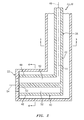
FIG. 2 is a side sectional illustration of a portion of a turbine engine fuel injector. -
FIG. 3 is a cross-sectional illustration of the fuel injector ofFIG. 2 at a first location. -
FIG. 4 is a cross-sectional illustration of the fuel injector ofFIG. 2 at a second location. -
FIGS. 5-12 are partial side illustrations of various alternative embodiments of a fluid coupling for the fuel injector ofFIG. 2 . -
FIG. 13 is a side cutaway illustration of a geared turbine engine. -
FIG. 1 is a block diagram of afluid delivery system 20 configured to deliver fluid to acomponent 22. Thefluid delivery system 20 may also be configured to receive fluid from thecomponent 22 as illustrated by the dashed line 24; e.g., circulate the fluid through thecomponent 22. - The
component 22 may be configured as or include a heat exchanger, a bearing, a gear train, a nozzle (seeFIG. 2 ), a combustor, an augmentor or a diffuser. For ease of description, thecomponent 22 is described below and illustrated inFIG. 2 as nozzle (e.g., a nozzle plate) of a gas turbine engine fuel injector. Thefluid delivery system 20, however, is not limited to delivering fluid to the exemplary components described above. For example, thecomponent 22 may be configured as any fluid receiving device or system of a turbine engine. Furthermore, thefluid delivery system 20 may also be configured to deliver the fluid to a plurality of components in serial and/or in parallel, some or all of which may have the same configuration or different configurations. - The fluid may be heat exchange fluid (e.g., liquid and/or gaseous coolant), and delivered to cool or heat the
component 22. The fluid may be actuator fluid (e.g., hydraulic liquid or compressed air), and delivered to actuate thecomponent 22. The fluid may be fuel, and delivered for distribution by or combustion within thecomponent 22. Thefluid delivery system 20, however, is not limited to delivering the exemplary fluids described above. - The
fluid delivery system 20 ofFIG. 1 includes afluid pump 26 and afluid source 28; e.g., a reservoir, a tank, a sump or an inlet. Thefluid delivery system 20 also includes afluid circuit 30 that fluidly couples thecomponents - The
fluid circuit 30 includes a plurality of fluid couplings 32-34. Each of the couplings 32-34 includes one or more coupling devices, which form a fluid flowpath through which the fluid may be directed between respective components. Examples of a coupling device include, but are not limited to, a conduit (e.g., a pipe, hose or duct), a manifold, a splitter, a valve, a regulator, a meter and a filter. - The
coupling 32 may extend between and fluidly couples thefluid source 28 to thefluid pump 26. Thecoupling 33 may extend between and fluidly couples thefluid pump 26 to thecomponent 22. Thecoupling 34 may extend between and fluidly couples thecomponent 22 to thefluid source 28. - At least one of the couplings 32-34 includes a
coupling assembly 36. Thiscoupling assembly 36 forms at least a portion of one of the couplings 32-34. For ease of description, thecoupling assembly 36 is described below and illustrated inFIG. 1 as being included in and forming at least a portion of thecoupling 33. However, in other embodiments, thecoupling assembly 36 may alternatively be included in and form at least a portion of one of theother couplings fluid circuit 30 may include a plurality of coupling assemblies, in parallel and/or in serial, that partially or completely form one or more of the couplings 32-34. - Referring to
FIG. 2 , thecoupling assembly 36 includes a plurality offluid conduits fluid conduits - The first
fluid conduit 38 may have a generallytubular sidewall 42 that forms afluid flowpath 44; e.g., a generally cylindrical fluid flowpath. This fluid flowpath 44 extends along acenterline 46 through the firstfluid conduit 38. - Referring to
FIG. 3 , thesidewall 42 may have an annular circular cross-sectional geometry. The firstfluid conduit 38, however, is not limited to such a cross-sectional geometry. Thesidewall 42, for example, may alternatively have an annular elongated, rectangular and/or irregular cross-sectional geometry. Furthermore, in some embodiments, the firstfluid conduit 38 may include a protrusion (or another sidewall) that provides thefluid flowpath 44 with an annular geometry as described below with reference to the second fluid conduit 40 (seeFIG. 4 ). Thecoupling assembly 36, of course, is not limited to the foregoing exemplary firstfluid conduit 38 configurations. - Referring to
FIG. 2 , the secondfluid conduit 40 may have a generally tubularouter sidewall 48 and aninner protrusion 50; e.g., a solid cylindrical object. Thesidewall 48 andprotrusion 50 are configured to form afluid flowpath 52; e.g., an annular fluid flowpath. This fluid flowpath 52 extends along acenterline 54 through the secondfluid conduit 40 and is fluidly coupled with thefluid flowpath 44. - Referring to
FIG. 4 , thesidewall 48 may have an annular circular cross-sectional geometry. The firstfluid conduit 38, however, is not limited to such a cross-sectional geometry. Thesidewall 48, for example, may alternatively have an annular elongated, rectangular and/or irregular cross-sectional geometry. Furthermore, in some embodiments, the secondfluid conduit 40 may be configured without theprotrusion 50, or theprotrusion 50 may be replaced with an inner sidewall. Thecoupling assembly 36, of course, is not limited to the foregoing exemplary secondfluid conduit 40 configurations. - The
fluid conduits fluid conduit 38 and the secondfluid conduit 40 are configured with cross-sections of different shapes. A cross-sectional area of thefluid flowpath 44 is also different (e.g., smaller) than a cross-sectional area of thefluid flowpath 52. However, in other embodiments, thefluid conduits fluid conduits centerlines - Referring to
FIG. 2 , the firstfluid conduit 38 is connected to the secondfluid conduit 40. An end of the firstfluid conduit 38, for example, is connected to an end of the secondfluid conduit 40. The firstfluid conduit 38 may be formed integral with the secondfluid conduit 40 as illustrated inFIG. 2 . Alternatively, referring toFIGS. 5-7 , the first and the secondfluid conduits - A joint 56 between the
fluid conduits FIG. 5 ), a modified bridle joint (seeFIG. 6 ), a butt joint and a shiplap joint. Examples of a joint with an interlocking configuration include, but are not limited to, a tabled splice joint (seeFIG. 7 ) and a dovetail joint. - It is worth noting, a rectangular joint 58 as illustrated in
FIG. 8 may provide a relatively abrupt transition between thefluid conduits conduits FIGS. 5-7 are configured to provide a relatively gradual transition between thefluid conduits fluid conduits fluid delivery system 20 is configured for delivering fuel in a turbine engine. In addition, the joint 56 embodiments ofFIGS. 5-7 may be more durable than the joint 58 embodiment ofFIG. 8 . - A gap (or gaps) between the
fluid conduits filler material 60. Examples of filler material include, but are not limited to, bonding material such as braze, weld and adhesive. Another example of filler material is a seal; e.g., a metal or elastomeric seal. Thefiller material 60 may be operable to at least partially thermally decouple the firstfluid conduit 38 from the secondfluid conduit 40. Thefiller material 60 may also or alternatively be operable to reduce stress at the joint 56, 58 where, for example, thefluid conduits -
FIG. 9 illustrates a hybrid joint 62 between the firstfluid conduit 38 and the secondfluid conduit 40. In this embodiments, the firstfluid conduit 38 is formed integral with the secondfluid conduit 40 where abridge 64 integrally connects theconduits bridge 64 may be useful when forming the first and the secondfluid conduits FIG. 2 , however, gaps extend between thefluid conduits filler material 60 as described above. Thus, a seal between thefluid conduits fluid conduit filler material 60 whereas the seal between thefluid conduits FIG. 2 may be provided solely by thefluid conduit - The
fluid conduits FIGS. 2 and5-9 . Alternatively, referring toFIGS. 10-12 , thefluid conduits intermediate fluid conduit 66. This intermediatefluid conduit 66 may be configured as a compliant intermediate fluid conduit. The intermediatefluid conduit 66, for example, may be configured to flex thereby allowing "towards and away" movement, "side-to-side" movement and/or "twisting" movement between thefluid conduits intermediate fluid conduit 66 may serve to reduce the transfer of forces and/or moments between thefluid conduits - The intermediate
fluid conduit 66 may be formed integral with the firstfluid conduit 38 and/or the secondfluid conduit 40. The intermediatefluid conduit 66 may extend along a substantially straight centerline as illustrated inFIG. 10 . Alternatively, theintermediate fluid conduit 66 may extend along a curved centerline as illustrated inFIG. 11 and/or a compound centerline as illustrated inFIG. 12 . Thecoupling assembly 36, however, is not limited to the exemplary intermediatefluid conduit 66 configurations described above and illustrated in the drawings. - The
coupling assembly 36 embodiments described above and illustrated in the drawings may be manufactured using various processes. One or more of thecoupling assembly components coupling assembly components - The
coupling assembly components fluid conduit 38 remains substantially constant as theconduit 38 extends along itscenterline 46. Similarly, the shape and the size of the secondfluid conduit 40, thebridge 64 and theintermediate fluid conduit 66 remain substantially constant as thesecomponents components respective components fluid conduits fluid conduits - The
coupling assembly components coupling assembly 36 may be formed include, but are not limited to, nickel (Ni), titanium (Ti), steel, stainless steel, cobalt (Co), chromium (Cr), tungsten (W), molybdenum (Mo) and/or alloys including one or more of the foregoing metals such as Waspaloy, Stellite, etc. The coupling assembly components, however, are not limited to being formed using additive manufacturing or the foregoing metal materials. For example, one or more of thecoupling assembly components - The
fluid delivery system 20 ofFIG. 1 may be configured with or included in various types of apparatuses and systems. Thefluid delivery system 20, for example, may be configured in a fuel delivery system, a lubrication system and/or a cooling or heating system of a turbine engine or any other type of engine. An example of such a turbine engine 94 (e.g., a geared turbofan engine) is illustrated inFIG. 13 . - The
turbine engine 94 ofFIG. 13 extends along anaxial centerline 96 between anupstream airflow inlet 98 and adownstream airflow exhaust 100. Theturbine engine 94 includes afan section 102, acompressor section 103, acombustor section 104 and aturbine section 105. Thecompressor section 103 includes a low pressure compressor (LPC)section 103A and a high pressure compressor (HPC)section 103B. Theturbine section 105 includes a high pressure turbine (HPT)section 105A and a low pressure turbine (LPT)section 105B. The engine sections 102-105 are arranged sequentially along thecenterline 96 within ahousing 106. - Each of the engine sections 102-103B, 105A and 105B includes a respective rotor 108-112. Each of these rotors 108-112 includes a plurality of rotor blades arranged circumferentially around and connected to one or more respective rotor disks. The rotor blades, for example, may be formed integral with or mechanically fastened, welded, brazed, adhered and/or otherwise attached to the respective rotor disk(s).
- The
fan rotor 108 is connected to agear train 114, for example, through afan shaft 116. Thegear train 114 and theLPC rotor 109 are connected to and driven by theLPT rotor 112 through alow speed shaft 117. TheHPC rotor 110 is connected to and driven by theHPT rotor 111 through ahigh speed shaft 118. The shafts 116-118 are rotatably supported by a plurality ofbearings 120; e.g., rolling element and/or thrust bearings. Each of thesebearings 120 is connected to theengine housing 106 by at least one stationary structure such as, for example, an annular support strut. - During operation, air enters the
turbine engine 94 through theairflow inlet 98, and is directed through thefan section 102 and into acore gas path 122 and abypass gas path 124. The air within thecore gas path 122 may be referred to as "core air". The air within thebypass gas path 124 may be referred to as "bypass air". The core air is directed through the engine sections 103-105 and exits theturbine engine 94 through theairflow exhaust 100 to provide forward engine thrust. Within thecombustor section 104, fuel is injected into a combustion chamber and mixed with the core air. This fuel-core air mixture is ignited to power theturbine engine 94. The bypass air is directed through thebypass gas path 124 and out of theturbine engine 94 through abypass nozzle 126 to provide additional forward engine thrust. Alternatively, at least some of the bypass air may be directed out of theturbine engine 94 through a thrust reverser to provide reverse engine thrust. - The
fluid delivery system 20 may be included in various turbine engines other than the one described above. Thefluid delivery system 20, for example, may be included in a geared turbine engine where a gear train connects one or more shafts to one or more rotors in a fan section, a compressor section and/or any other engine section. Alternatively, thefluid delivery system 20 may be included in a turbine engine configured without a gear train. Thefluid delivery system 20 may be included in a geared or non-geared turbine engine configured with a single spool, with two spools (e.g., seeFIG. 13 ), or with more than two spools. The turbine engine may be configured as a turbofan engine, a turbojet engine, a propfan engine, or any other type of turbine engine. The present invention therefore is not limited to any particular turbine engine types or configurations. Furthermore, while thefluid delivery system 20 is described above as being included in a turbine engine, the system may also be configured with various non-turbine engine systems; e.g., HVAC systems, automobile systems, etc. - While various embodiments of the present invention have been disclosed, it will be apparent to those of ordinary skill in the art that many more embodiments and implementations are possible within the scope of the invention. For example, the present invention as described herein includes several aspects and embodiments that include particular features. Although these features may be described individually, it is within the scope of the present invention that some or all of these features may be combined with any one of the aspects and remain within the scope of the invention. Accordingly, the present invention is not to be restricted except in light of the attached claims and their equivalents.
Claims (15)
- A method involving an additive manufacturing system, the method comprising:forming a first fluid conduit (38) using the additive manufacturing system; andproviding a fluid coupling (32, 33, 34), the fluid coupling (32, 33, 34) including the first fluid conduit (38) and a second fluid conduit (40), the first fluid conduit (38) connected to and fluidly coupled with the second fluid conduit (40), wherein the first fluid conduit (38) has a first configuration, and the second fluid conduit (40) has a second configuration that is different than the first configuration.
- The method of claim 1, further comprising forming the second fluid conduit (40) using the additive manufacturing system, and optionally wherein the second fluid conduit (40) is formed integral with the first fluid conduit (38).
- The method of claim 1 or 2, wherein the first fluid conduit (38) is connected to and fluidly coupled with the second fluid conduit (40) during the forming of the first and the second fluid conduits (38, 40).
- The method of claims 1 or 2, further comprising fluidly coupling the first fluid conduit (38) to the second fluid conduit (40) after the forming of the first and the second fluid conduits (38, 40).
- The method of any preceding claim, further comprising connecting and fluidly coupling the first fluid conduit (38) to the second fluid conduit (40), wherein the first fluid conduit (38) is formed discretely from the second fluid conduit (40).
- The method of any preceding claim, wherein a joint (56) between the first fluid conduit (38) and the second fluid conduit (40) has a non-rectangular configuration.
- The method of any preceding claim, wherein the first fluid conduit (38) interlocks with the second fluid conduit (40).
- The method of any preceding claim, further comprising connecting and fluidly coupling the first fluid conduit (38) to the second fluid conduit (40) through a compliant intermediate fluid conduit (66), and optionally wherein the intermediate fluid conduit (66) is formed integral with the first and the second fluid conduits (38, 40).
- The method of any preceding claim, wherein
the first fluid conduit (38) has a cross-section with a first shape; and
the second fluid conduit (40) has a cross-section with a second shape that is different than the first shape. - The method of any preceding claim, wherein
the first fluid conduit (38) forms a first flowpath (44) with a first cross-sectional area; and
the second fluid conduit (40) forms a second flowpath (52) with a second cross-sectional area that is different than the first cross-sectional area. - An assembly for a fluid delivery system (20), the assembly comprising:a fluid coupling including a first fluid conduit (38), a second fluid conduit (40) and a compliant intermediate fluid conduit (66);the intermediate fluid conduit (66) connecting and fluidly coupling the first fluid conduit (38) to the second fluid conduit (40); andthe intermediate fluid conduit (66) formed integral with the first and the second fluid conduits (38, 40).
- The assembly of claim 11, wherein the intermediate fluid conduit (66):is adapted to allow movement between the first and the second fluid conduits (38, 40); and/orextends along a substantially straight centerline or along a curved and/or compound centerline.
- The assembly of claim 11 or 12, wherein the first fluid conduit (38) has a first configuration, and the second fluid conduit (40) has a second configuration that is different than the first configuration.
- The assembly of claim 11, 12 or 13, further comprising:a fluid source (28); anda turbine engine component fluidly coupled to the fluid source (28) through the fluid coupling (32, 33, 34).
- An assembly for a fluid delivery system, the assembly comprising:a fluid coupling including a first fluid conduit and a second fluid conduit;the first fluid conduit connected to and fluidly coupled with the second fluid conduit at a joint; andthe first fluid conduit interlocked with the second fluid conduit at the joint, and optionally wherein the first fluid conduit is formed integral with the second fluid conduit.
Applications Claiming Priority (1)
| Application Number | Priority Date | Filing Date | Title |
|---|---|---|---|
| US201461991163P | 2014-05-09 | 2014-05-09 |
Publications (2)
| Publication Number | Publication Date |
|---|---|
| EP2942510A1 true EP2942510A1 (en) | 2015-11-11 |
| EP2942510B1 EP2942510B1 (en) | 2022-06-29 |
Family
ID=53510574
Family Applications (1)
| Application Number | Title | Priority Date | Filing Date |
|---|---|---|---|
| EP15167223.5A Active EP2942510B1 (en) | 2014-05-09 | 2015-05-11 | Methods for additive manufacturing of fluid couplings |
Country Status (2)
| Country | Link |
|---|---|
| US (3) | US9857002B2 (en) |
| EP (1) | EP2942510B1 (en) |
Cited By (1)
| Publication number | Priority date | Publication date | Assignee | Title |
|---|---|---|---|---|
| WO2018005106A1 (en) * | 2016-06-30 | 2018-01-04 | General Electric Company | Integral fluid conduit |
Families Citing this family (26)
| Publication number | Priority date | Publication date | Assignee | Title |
|---|---|---|---|---|
| US10773863B2 (en) | 2011-06-22 | 2020-09-15 | Sartorius Stedim North America Inc. | Vessel closures and methods for using and manufacturing same |
| GB201607372D0 (en) * | 2016-04-28 | 2016-06-15 | Rolls Royce Plc | Flexible hose |
| US11235528B2 (en) | 2017-09-02 | 2022-02-01 | R3 Printing, Inc. | Carriageless print head assembly for extrusion-based additive construction |
| US12252391B2 (en) | 2017-11-14 | 2025-03-18 | Sartorius Stedim North America Inc. | System for simultaneous distribution of fluid to multiple vessels and method of using the same |
| US11577953B2 (en) | 2017-11-14 | 2023-02-14 | Sartorius Stedim North America, Inc. | System for simultaneous distribution of fluid to multiple vessels and method of using the same |
| US11319201B2 (en) | 2019-07-23 | 2022-05-03 | Sartorius Stedim North America Inc. | System for simultaneous filling of multiple containers |
| EP3710361A4 (en) | 2017-11-14 | 2021-08-11 | Sartorius Stedim North America Inc. | FLUID TRANSFER KIT WITH A JUNCTION HAVING MULTIPLE FLUID WAYS |
| US11691866B2 (en) | 2017-11-14 | 2023-07-04 | Sartorius Stedim North America Inc. | System for simultaneous distribution of fluid to multiple vessels and method of using the same |
| DE102018115854A1 (en) * | 2018-06-29 | 2020-01-02 | Witzenmann Gmbh | Metallic pipe arrangement with additively manufactured connector |
| US12194620B2 (en) | 2018-10-15 | 2025-01-14 | Oliver Crisipin Robotics Limited | Selectively flexible extension tool |
| US11707819B2 (en) | 2018-10-15 | 2023-07-25 | General Electric Company | Selectively flexible extension tool |
| US10821678B2 (en) | 2018-11-09 | 2020-11-03 | Raytheon Technologies Corporation | Additive manufactured multi-portion article |
| US11702955B2 (en) | 2019-01-14 | 2023-07-18 | General Electric Company | Component repair system and method |
| US11369985B2 (en) | 2019-10-04 | 2022-06-28 | Delavan Inc | Fluid conduits with heat shielding |
| US12405187B2 (en) | 2019-10-04 | 2025-09-02 | General Electric Company | Insertion apparatus for use with rotary machines |
| US11692650B2 (en) | 2020-01-23 | 2023-07-04 | General Electric Company | Selectively flexible extension tool |
| US11752622B2 (en) | 2020-01-23 | 2023-09-12 | General Electric Company | Extension tool having a plurality of links |
| US11613003B2 (en) | 2020-01-24 | 2023-03-28 | General Electric Company | Line assembly for an extension tool having a plurality of links |
| US11970279B2 (en) | 2020-02-21 | 2024-04-30 | General Electric Company | Control system and methods of controlling an engine-mounting link system |
| US11939070B2 (en) | 2020-02-21 | 2024-03-26 | General Electric Company | Engine-mounting links that have an adjustable inclination angle |
| US11371437B2 (en) | 2020-03-10 | 2022-06-28 | Oliver Crispin Robotics Limited | Insertion tool |
| US12091981B2 (en) | 2020-06-11 | 2024-09-17 | General Electric Company | Insertion tool and method |
| US12416800B2 (en) | 2021-01-08 | 2025-09-16 | General Electric Company | Insertion tool |
| US12504616B2 (en) | 2021-01-08 | 2025-12-23 | General Electric Company | Insertion tool |
| US11654547B2 (en) | 2021-03-31 | 2023-05-23 | General Electric Company | Extension tool |
| US12239127B2 (en) | 2021-07-28 | 2025-03-04 | Sartorius Stedim North America Inc. | Thermal capacitors, systems, and methods for rapid freezing or heating of biological materials |
Citations (3)
| Publication number | Priority date | Publication date | Assignee | Title |
|---|---|---|---|---|
| US20090255102A1 (en) * | 2008-04-11 | 2009-10-15 | Mcmasters Marie Ann | Repair of fuel nozzle component |
| WO2009148680A2 (en) * | 2008-04-11 | 2009-12-10 | General Electric Company | Unitary conduit for transporting fluids and method of manufacturing |
| WO2013188723A1 (en) * | 2012-06-15 | 2013-12-19 | General Electric Company | Fluid conduit |
Family Cites Families (27)
| Publication number | Priority date | Publication date | Assignee | Title |
|---|---|---|---|---|
| US290045A (en) * | 1883-12-11 | hardy | ||
| US2595705A (en) * | 1949-03-08 | 1952-05-06 | Sr Ernest E Rosecrans | Insert fitting |
| GB8620071D0 (en) * | 1986-08-18 | 1986-10-01 | British Gas Corp | Structures of polymeric plastics material |
| US5328211A (en) * | 1992-11-12 | 1994-07-12 | Carrier Cororation | Crush tube fluid connection |
| US6240731B1 (en) | 1997-12-31 | 2001-06-05 | United Technologies Corporation | Low NOx combustor for gas turbine engine |
| US6412272B1 (en) | 1998-12-29 | 2002-07-02 | United Technologies Corporation | Fuel nozzle guide for gas turbine engine and method of assembly/disassembly |
| US7323143B2 (en) * | 2000-05-25 | 2008-01-29 | President And Fellows Of Harvard College | Microfluidic systems including three-dimensionally arrayed channel networks |
| US6645432B1 (en) * | 2000-05-25 | 2003-11-11 | President & Fellows Of Harvard College | Microfluidic systems including three-dimensionally arrayed channel networks |
| US7007864B2 (en) | 2002-11-08 | 2006-03-07 | United Technologies Corporation | Fuel nozzle design |
| US6935117B2 (en) | 2003-10-23 | 2005-08-30 | United Technologies Corporation | Turbine engine fuel injector |
| US20070236018A1 (en) * | 2005-09-06 | 2007-10-11 | Northrop Grumman Corporation | Method for joining parts fabricated via selective laser sintering while maintaining proper alignment |
| US7777155B2 (en) | 2007-02-21 | 2010-08-17 | United Technologies Corporation | System and method for an integrated additive manufacturing cell for complex components |
| US8127547B2 (en) | 2007-06-07 | 2012-03-06 | United Technologies Corporation | Gas turbine engine with air and fuel cooling system |
| US20090255256A1 (en) * | 2008-04-11 | 2009-10-15 | General Electric Company | Method of manufacturing combustor components |
| EP2221456B1 (en) | 2009-02-18 | 2011-09-28 | Quasar S.P.A. | Drain collector |
| US9383097B2 (en) * | 2011-03-10 | 2016-07-05 | Rolls-Royce Plc | Systems and method for cooling a staged airblast fuel injector |
| EP2715204A2 (en) * | 2011-06-02 | 2014-04-09 | A. Raymond et Cie | Connectors manufactured by three-dimensional printing |
| US8978711B2 (en) * | 2012-01-17 | 2015-03-17 | Watanabe Seisakusho Co., Ltd. | Double pipe and coupling structure for the pipe |
| US8915728B2 (en) * | 2012-01-27 | 2014-12-23 | United Technologies Corporation | Multi-dimensional component build system and process |
| US9200855B2 (en) * | 2012-03-06 | 2015-12-01 | Honeywell International Inc. | Tubular heat exchange systems |
| CA2879869C (en) * | 2012-07-20 | 2020-07-14 | Mag Aerospace Industries, Llc | Composite waste and water transport elements and methods of manufacture for use on aircraft |
| US20140093384A1 (en) | 2012-09-28 | 2014-04-03 | United Technologies Corporation | Method of Manufacturing Complex Shaped Component |
| US9272437B2 (en) * | 2012-10-31 | 2016-03-01 | Flow International Corporation | Fluid distribution components of high-pressure fluid jet systems |
| AU2013362817B2 (en) * | 2012-12-21 | 2018-03-08 | Lifting Point Pty Ltd | Plumbing drainage coupling member and associated method |
| US8678348B1 (en) * | 2013-07-02 | 2014-03-25 | Landtec International Holdings, Llc | Gas flow control valve |
| US9416662B2 (en) * | 2013-09-03 | 2016-08-16 | General Electric Company | Method and system for providing cooling for turbine components |
| US20150165681A1 (en) * | 2013-12-18 | 2015-06-18 | Board Of Regents, The University Of Texas System | Real-time process control for additive manufacturing |
-
2015
- 2015-05-08 US US14/707,713 patent/US9857002B2/en active Active
- 2015-05-11 EP EP15167223.5A patent/EP2942510B1/en active Active
-
2017
- 2017-11-29 US US15/825,947 patent/US10683952B2/en active Active
-
2020
- 2020-06-11 US US16/899,197 patent/US20200300389A1/en not_active Abandoned
Patent Citations (3)
| Publication number | Priority date | Publication date | Assignee | Title |
|---|---|---|---|---|
| US20090255102A1 (en) * | 2008-04-11 | 2009-10-15 | Mcmasters Marie Ann | Repair of fuel nozzle component |
| WO2009148680A2 (en) * | 2008-04-11 | 2009-12-10 | General Electric Company | Unitary conduit for transporting fluids and method of manufacturing |
| WO2013188723A1 (en) * | 2012-06-15 | 2013-12-19 | General Electric Company | Fluid conduit |
Cited By (4)
| Publication number | Priority date | Publication date | Assignee | Title |
|---|---|---|---|---|
| WO2018005106A1 (en) * | 2016-06-30 | 2018-01-04 | General Electric Company | Integral fluid conduit |
| CN109415980A (en) * | 2016-06-30 | 2019-03-01 | 通用电气公司 | Integrated fluid conduit |
| CN109415980B (en) * | 2016-06-30 | 2021-10-22 | 通用电气公司 | Integrated fluid piping |
| US11262003B2 (en) | 2016-06-30 | 2022-03-01 | General Electric Company | Integral fluid conduit |
Also Published As
| Publication number | Publication date |
|---|---|
| US20180087696A1 (en) | 2018-03-29 |
| US10683952B2 (en) | 2020-06-16 |
| US20150323107A1 (en) | 2015-11-12 |
| US20200300389A1 (en) | 2020-09-24 |
| US9857002B2 (en) | 2018-01-02 |
| EP2942510B1 (en) | 2022-06-29 |
Similar Documents
| Publication | Publication Date | Title |
|---|---|---|
| US20200300389A1 (en) | Fluid couplings and methods for additive manufacturing thereof | |
| US10934890B2 (en) | Shrouded conduit for arranging a fluid flowpath | |
| US12055043B2 (en) | Seals and methods of making seals | |
| US20150167983A1 (en) | Bundled tube fuel injector tube tip | |
| EP3054252B1 (en) | Heat exchanger system with additively manufactured heat transfer tube that follows a non-linear path | |
| US11021963B2 (en) | Monolithic body including an internal passage with a generally teardrop shaped cross-sectional geometry | |
| EP2927426A1 (en) | Cooling system with a bearing compartment bypass | |
| CN110214218A (en) | Turbine star frame with additional core | |
| US9976431B2 (en) | Mid-turbine frame and gas turbine engine including same | |
| EP3832074B1 (en) | Integral engine case precooler | |
| EP3081762B1 (en) | Static axial brush seal with dual bristle packs | |
| EP4481314A1 (en) | Composite heat exchange apparatus for a turbine engine | |
| EP3550106B1 (en) | Cooling air for gas turbine engine with thermally isolated cooling air delivery | |
| EP4183978A1 (en) | Disk bore compartment seals for gas turbine engines | |
| EP3189922B1 (en) | Advanced braze joint for tube-to-tube connection | |
| US10968746B2 (en) | Serpentine turn cover for gas turbine stator vane assembly | |
| US20170328213A1 (en) | Engine component wall with a cooling circuit | |
| US20160237822A1 (en) | Blade restoration using shroud plating | |
| US12516610B2 (en) | Oil passage built into bearing compartment spring | |
| EP4513088A1 (en) | Methods of repairing tubes in bundled tube fuel injectors | |
| CN106415133B (en) | Combustor assembly for gas turbine engine with braze layer with centerline eutectic zone |
Legal Events
| Date | Code | Title | Description |
|---|---|---|---|
| PUAI | Public reference made under article 153(3) epc to a published international application that has entered the european phase |
Free format text: ORIGINAL CODE: 0009012 |
|
| AK | Designated contracting states |
Kind code of ref document: A1 Designated state(s): AL AT BE BG CH CY CZ DE DK EE ES FI FR GB GR HR HU IE IS IT LI LT LU LV MC MK MT NL NO PL PT RO RS SE SI SK SM TR |
|
| AX | Request for extension of the european patent |
Extension state: BA ME |
|
| 17P | Request for examination filed |
Effective date: 20160511 |
|
| RBV | Designated contracting states (corrected) |
Designated state(s): AL AT BE BG CH CY CZ DE DK EE ES FI FR GB GR HR HU IE IS IT LI LT LU LV MC MK MT NL NO PL PT RO RS SE SI SK SM TR |
|
| 17Q | First examination report despatched |
Effective date: 20160912 |
|
| STAA | Information on the status of an ep patent application or granted ep patent |
Free format text: STATUS: EXAMINATION IS IN PROGRESS |
|
| RAP1 | Party data changed (applicant data changed or rights of an application transferred) |
Owner name: UNITED TECHNOLOGIES CORPORATION |
|
| RIN1 | Information on inventor provided before grant (corrected) |
Inventor name: MOURA, DENNIS M. Inventor name: SCHIRTZINGER, GARY A. Inventor name: OTT, JOE Inventor name: FUNK, STANLEY J. Inventor name: KIRONN, LEXIA Inventor name: RUP, JOHN J., JR. Inventor name: STEMPINSKI, SHAWN Inventor name: COFFEY, ROGER O. |
|
| RAP1 | Party data changed (applicant data changed or rights of an application transferred) |
Owner name: RAYTHEON TECHNOLOGIES CORPORATION |
|
| REG | Reference to a national code |
Ref country code: DE Ref legal event code: R079 Ref document number: 602015079628 Country of ref document: DE Free format text: PREVIOUS MAIN CLASS: F02C0007220000 Ipc: B33Y0010000000 |
|
| GRAP | Despatch of communication of intention to grant a patent |
Free format text: ORIGINAL CODE: EPIDOSNIGR1 |
|
| STAA | Information on the status of an ep patent application or granted ep patent |
Free format text: STATUS: GRANT OF PATENT IS INTENDED |
|
| RIC1 | Information provided on ipc code assigned before grant |
Ipc: F02C 7/22 20060101ALI20211125BHEP Ipc: B29C 64/10 20170101ALI20211125BHEP Ipc: B33Y 80/00 20150101ALI20211125BHEP Ipc: B33Y 10/00 20150101AFI20211125BHEP |
|
| INTG | Intention to grant announced |
Effective date: 20211223 |
|
| GRAS | Grant fee paid |
Free format text: ORIGINAL CODE: EPIDOSNIGR3 |
|
| GRAA | (expected) grant |
Free format text: ORIGINAL CODE: 0009210 |
|
| STAA | Information on the status of an ep patent application or granted ep patent |
Free format text: STATUS: THE PATENT HAS BEEN GRANTED |
|
| AK | Designated contracting states |
Kind code of ref document: B1 Designated state(s): AL AT BE BG CH CY CZ DE DK EE ES FI FR GB GR HR HU IE IS IT LI LT LU LV MC MK MT NL NO PL PT RO RS SE SI SK SM TR |
|
| REG | Reference to a national code |
Ref country code: GB Ref legal event code: FG4D |
|
| REG | Reference to a national code |
Ref country code: CH Ref legal event code: EP |
|
| REG | Reference to a national code |
Ref country code: AT Ref legal event code: REF Ref document number: 1501064 Country of ref document: AT Kind code of ref document: T Effective date: 20220715 |
|
| REG | Reference to a national code |
Ref country code: IE Ref legal event code: FG4D |
|
| REG | Reference to a national code |
Ref country code: DE Ref legal event code: R096 Ref document number: 602015079628 Country of ref document: DE |
|
| REG | Reference to a national code |
Ref country code: LT Ref legal event code: MG9D |
|
| PG25 | Lapsed in a contracting state [announced via postgrant information from national office to epo] |
Ref country code: SE Free format text: LAPSE BECAUSE OF FAILURE TO SUBMIT A TRANSLATION OF THE DESCRIPTION OR TO PAY THE FEE WITHIN THE PRESCRIBED TIME-LIMIT Effective date: 20220629 Ref country code: NO Free format text: LAPSE BECAUSE OF FAILURE TO SUBMIT A TRANSLATION OF THE DESCRIPTION OR TO PAY THE FEE WITHIN THE PRESCRIBED TIME-LIMIT Effective date: 20220929 Ref country code: LT Free format text: LAPSE BECAUSE OF FAILURE TO SUBMIT A TRANSLATION OF THE DESCRIPTION OR TO PAY THE FEE WITHIN THE PRESCRIBED TIME-LIMIT Effective date: 20220629 Ref country code: HR Free format text: LAPSE BECAUSE OF FAILURE TO SUBMIT A TRANSLATION OF THE DESCRIPTION OR TO PAY THE FEE WITHIN THE PRESCRIBED TIME-LIMIT Effective date: 20220629 Ref country code: GR Free format text: LAPSE BECAUSE OF FAILURE TO SUBMIT A TRANSLATION OF THE DESCRIPTION OR TO PAY THE FEE WITHIN THE PRESCRIBED TIME-LIMIT Effective date: 20220930 Ref country code: FI Free format text: LAPSE BECAUSE OF FAILURE TO SUBMIT A TRANSLATION OF THE DESCRIPTION OR TO PAY THE FEE WITHIN THE PRESCRIBED TIME-LIMIT Effective date: 20220629 Ref country code: BG Free format text: LAPSE BECAUSE OF FAILURE TO SUBMIT A TRANSLATION OF THE DESCRIPTION OR TO PAY THE FEE WITHIN THE PRESCRIBED TIME-LIMIT Effective date: 20220929 |
|
| REG | Reference to a national code |
Ref country code: NL Ref legal event code: MP Effective date: 20220629 |
|
| REG | Reference to a national code |
Ref country code: AT Ref legal event code: MK05 Ref document number: 1501064 Country of ref document: AT Kind code of ref document: T Effective date: 20220629 |
|
| PG25 | Lapsed in a contracting state [announced via postgrant information from national office to epo] |
Ref country code: RS Free format text: LAPSE BECAUSE OF FAILURE TO SUBMIT A TRANSLATION OF THE DESCRIPTION OR TO PAY THE FEE WITHIN THE PRESCRIBED TIME-LIMIT Effective date: 20220629 Ref country code: LV Free format text: LAPSE BECAUSE OF FAILURE TO SUBMIT A TRANSLATION OF THE DESCRIPTION OR TO PAY THE FEE WITHIN THE PRESCRIBED TIME-LIMIT Effective date: 20220629 |
|
| PG25 | Lapsed in a contracting state [announced via postgrant information from national office to epo] |
Ref country code: NL Free format text: LAPSE BECAUSE OF FAILURE TO SUBMIT A TRANSLATION OF THE DESCRIPTION OR TO PAY THE FEE WITHIN THE PRESCRIBED TIME-LIMIT Effective date: 20220629 |
|
| PG25 | Lapsed in a contracting state [announced via postgrant information from national office to epo] |
Ref country code: SM Free format text: LAPSE BECAUSE OF FAILURE TO SUBMIT A TRANSLATION OF THE DESCRIPTION OR TO PAY THE FEE WITHIN THE PRESCRIBED TIME-LIMIT Effective date: 20220629 Ref country code: SK Free format text: LAPSE BECAUSE OF FAILURE TO SUBMIT A TRANSLATION OF THE DESCRIPTION OR TO PAY THE FEE WITHIN THE PRESCRIBED TIME-LIMIT Effective date: 20220629 Ref country code: RO Free format text: LAPSE BECAUSE OF FAILURE TO SUBMIT A TRANSLATION OF THE DESCRIPTION OR TO PAY THE FEE WITHIN THE PRESCRIBED TIME-LIMIT Effective date: 20220629 Ref country code: PT Free format text: LAPSE BECAUSE OF FAILURE TO SUBMIT A TRANSLATION OF THE DESCRIPTION OR TO PAY THE FEE WITHIN THE PRESCRIBED TIME-LIMIT Effective date: 20221031 Ref country code: ES Free format text: LAPSE BECAUSE OF FAILURE TO SUBMIT A TRANSLATION OF THE DESCRIPTION OR TO PAY THE FEE WITHIN THE PRESCRIBED TIME-LIMIT Effective date: 20220629 Ref country code: EE Free format text: LAPSE BECAUSE OF FAILURE TO SUBMIT A TRANSLATION OF THE DESCRIPTION OR TO PAY THE FEE WITHIN THE PRESCRIBED TIME-LIMIT Effective date: 20220629 Ref country code: AT Free format text: LAPSE BECAUSE OF FAILURE TO SUBMIT A TRANSLATION OF THE DESCRIPTION OR TO PAY THE FEE WITHIN THE PRESCRIBED TIME-LIMIT Effective date: 20220629 |
|
| PG25 | Lapsed in a contracting state [announced via postgrant information from national office to epo] |
Ref country code: PL Free format text: LAPSE BECAUSE OF FAILURE TO SUBMIT A TRANSLATION OF THE DESCRIPTION OR TO PAY THE FEE WITHIN THE PRESCRIBED TIME-LIMIT Effective date: 20220629 Ref country code: IS Free format text: LAPSE BECAUSE OF FAILURE TO SUBMIT A TRANSLATION OF THE DESCRIPTION OR TO PAY THE FEE WITHIN THE PRESCRIBED TIME-LIMIT Effective date: 20221029 |
|
| REG | Reference to a national code |
Ref country code: DE Ref legal event code: R097 Ref document number: 602015079628 Country of ref document: DE |
|
| PG25 | Lapsed in a contracting state [announced via postgrant information from national office to epo] |
Ref country code: AL Free format text: LAPSE BECAUSE OF FAILURE TO SUBMIT A TRANSLATION OF THE DESCRIPTION OR TO PAY THE FEE WITHIN THE PRESCRIBED TIME-LIMIT Effective date: 20220629 |
|
| PG25 | Lapsed in a contracting state [announced via postgrant information from national office to epo] |
Ref country code: DK Free format text: LAPSE BECAUSE OF FAILURE TO SUBMIT A TRANSLATION OF THE DESCRIPTION OR TO PAY THE FEE WITHIN THE PRESCRIBED TIME-LIMIT Effective date: 20220629 Ref country code: CZ Free format text: LAPSE BECAUSE OF FAILURE TO SUBMIT A TRANSLATION OF THE DESCRIPTION OR TO PAY THE FEE WITHIN THE PRESCRIBED TIME-LIMIT Effective date: 20220629 |
|
| PLBE | No opposition filed within time limit |
Free format text: ORIGINAL CODE: 0009261 |
|
| STAA | Information on the status of an ep patent application or granted ep patent |
Free format text: STATUS: NO OPPOSITION FILED WITHIN TIME LIMIT |
|
| 26N | No opposition filed |
Effective date: 20230330 |
|
| P01 | Opt-out of the competence of the unified patent court (upc) registered |
Effective date: 20230520 |
|
| PG25 | Lapsed in a contracting state [announced via postgrant information from national office to epo] |
Ref country code: SI Free format text: LAPSE BECAUSE OF FAILURE TO SUBMIT A TRANSLATION OF THE DESCRIPTION OR TO PAY THE FEE WITHIN THE PRESCRIBED TIME-LIMIT Effective date: 20220629 |
|
| REG | Reference to a national code |
Ref country code: CH Ref legal event code: PL |
|
| PG25 | Lapsed in a contracting state [announced via postgrant information from national office to epo] |
Ref country code: MC Free format text: LAPSE BECAUSE OF FAILURE TO SUBMIT A TRANSLATION OF THE DESCRIPTION OR TO PAY THE FEE WITHIN THE PRESCRIBED TIME-LIMIT Effective date: 20220629 |
|
| REG | Reference to a national code |
Ref country code: BE Ref legal event code: MM Effective date: 20230531 |
|
| PG25 | Lapsed in a contracting state [announced via postgrant information from national office to epo] |
Ref country code: MC Free format text: LAPSE BECAUSE OF FAILURE TO SUBMIT A TRANSLATION OF THE DESCRIPTION OR TO PAY THE FEE WITHIN THE PRESCRIBED TIME-LIMIT Effective date: 20220629 Ref country code: LU Free format text: LAPSE BECAUSE OF NON-PAYMENT OF DUE FEES Effective date: 20230511 Ref country code: LI Free format text: LAPSE BECAUSE OF NON-PAYMENT OF DUE FEES Effective date: 20230531 Ref country code: IT Free format text: LAPSE BECAUSE OF FAILURE TO SUBMIT A TRANSLATION OF THE DESCRIPTION OR TO PAY THE FEE WITHIN THE PRESCRIBED TIME-LIMIT Effective date: 20220629 Ref country code: CH Free format text: LAPSE BECAUSE OF NON-PAYMENT OF DUE FEES Effective date: 20230531 |
|
| REG | Reference to a national code |
Ref country code: IE Ref legal event code: MM4A |
|
| PG25 | Lapsed in a contracting state [announced via postgrant information from national office to epo] |
Ref country code: IE Free format text: LAPSE BECAUSE OF NON-PAYMENT OF DUE FEES Effective date: 20230511 |
|
| PG25 | Lapsed in a contracting state [announced via postgrant information from national office to epo] |
Ref country code: IE Free format text: LAPSE BECAUSE OF NON-PAYMENT OF DUE FEES Effective date: 20230511 |
|
| PG25 | Lapsed in a contracting state [announced via postgrant information from national office to epo] |
Ref country code: BE Free format text: LAPSE BECAUSE OF NON-PAYMENT OF DUE FEES Effective date: 20230531 |
|
| PG25 | Lapsed in a contracting state [announced via postgrant information from national office to epo] |
Ref country code: BG Free format text: LAPSE BECAUSE OF FAILURE TO SUBMIT A TRANSLATION OF THE DESCRIPTION OR TO PAY THE FEE WITHIN THE PRESCRIBED TIME-LIMIT Effective date: 20220629 |
|
| PG25 | Lapsed in a contracting state [announced via postgrant information from national office to epo] |
Ref country code: BG Free format text: LAPSE BECAUSE OF FAILURE TO SUBMIT A TRANSLATION OF THE DESCRIPTION OR TO PAY THE FEE WITHIN THE PRESCRIBED TIME-LIMIT Effective date: 20220629 |
|
| PGFP | Annual fee paid to national office [announced via postgrant information from national office to epo] |
Ref country code: DE Payment date: 20250423 Year of fee payment: 11 |
|
| PGFP | Annual fee paid to national office [announced via postgrant information from national office to epo] |
Ref country code: GB Payment date: 20250423 Year of fee payment: 11 |
|
| PGFP | Annual fee paid to national office [announced via postgrant information from national office to epo] |
Ref country code: FR Payment date: 20250423 Year of fee payment: 11 |
|
| PG25 | Lapsed in a contracting state [announced via postgrant information from national office to epo] |
Ref country code: CY Free format text: LAPSE BECAUSE OF FAILURE TO SUBMIT A TRANSLATION OF THE DESCRIPTION OR TO PAY THE FEE WITHIN THE PRESCRIBED TIME-LIMIT; INVALID AB INITIO Effective date: 20150511 |
|
| PG25 | Lapsed in a contracting state [announced via postgrant information from national office to epo] |
Ref country code: HU Free format text: LAPSE BECAUSE OF FAILURE TO SUBMIT A TRANSLATION OF THE DESCRIPTION OR TO PAY THE FEE WITHIN THE PRESCRIBED TIME-LIMIT; INVALID AB INITIO Effective date: 20150511 |
|
| REG | Reference to a national code |
Ref country code: DE Ref legal event code: R081 Ref document number: 602015079628 Country of ref document: DE Owner name: RTX CORPORATION (N.D.GES.D. STAATES DELAWARE),, US Free format text: FORMER OWNER: RAYTHEON TECHNOLOGIES CORPORATION, FARMINGTON, CT, US |
|
| PG25 | Lapsed in a contracting state [announced via postgrant information from national office to epo] |
Ref country code: TR Free format text: LAPSE BECAUSE OF FAILURE TO SUBMIT A TRANSLATION OF THE DESCRIPTION OR TO PAY THE FEE WITHIN THE PRESCRIBED TIME-LIMIT Effective date: 20220629 |