EP2942496A1 - Oxy boiler power plant with a heat integrated air separation unit - Google Patents
Oxy boiler power plant with a heat integrated air separation unit Download PDFInfo
- Publication number
- EP2942496A1 EP2942496A1 EP14290140.4A EP14290140A EP2942496A1 EP 2942496 A1 EP2942496 A1 EP 2942496A1 EP 14290140 A EP14290140 A EP 14290140A EP 2942496 A1 EP2942496 A1 EP 2942496A1
- Authority
- EP
- European Patent Office
- Prior art keywords
- power plant
- steam
- condensate
- boiler power
- coal fired
- Prior art date
- Legal status (The legal status is an assumption and is not a legal conclusion. Google has not performed a legal analysis and makes no representation as to the accuracy of the status listed.)
- Granted
Links
Images

Classifications
-
- F—MECHANICAL ENGINEERING; LIGHTING; HEATING; WEAPONS; BLASTING
- F23—COMBUSTION APPARATUS; COMBUSTION PROCESSES
- F23L—SUPPLYING AIR OR NON-COMBUSTIBLE LIQUIDS OR GASES TO COMBUSTION APPARATUS IN GENERAL ; VALVES OR DAMPERS SPECIALLY ADAPTED FOR CONTROLLING AIR SUPPLY OR DRAUGHT IN COMBUSTION APPARATUS; INDUCING DRAUGHT IN COMBUSTION APPARATUS; TOPS FOR CHIMNEYS OR VENTILATING SHAFTS; TERMINALS FOR FLUES
- F23L7/00—Supplying non-combustible liquids or gases, other than air, to the fire, e.g. oxygen, steam
- F23L7/007—Supplying oxygen or oxygen-enriched air
-
- F—MECHANICAL ENGINEERING; LIGHTING; HEATING; WEAPONS; BLASTING
- F01—MACHINES OR ENGINES IN GENERAL; ENGINE PLANTS IN GENERAL; STEAM ENGINES
- F01K—STEAM ENGINE PLANTS; STEAM ACCUMULATORS; ENGINE PLANTS NOT OTHERWISE PROVIDED FOR; ENGINES USING SPECIAL WORKING FLUIDS OR CYCLES
- F01K13/00—General layout or general methods of operation of complete plants
-
- F—MECHANICAL ENGINEERING; LIGHTING; HEATING; WEAPONS; BLASTING
- F01—MACHINES OR ENGINES IN GENERAL; ENGINE PLANTS IN GENERAL; STEAM ENGINES
- F01K—STEAM ENGINE PLANTS; STEAM ACCUMULATORS; ENGINE PLANTS NOT OTHERWISE PROVIDED FOR; ENGINES USING SPECIAL WORKING FLUIDS OR CYCLES
- F01K17/00—Using steam or condensate extracted or exhausted from steam engine plant
- F01K17/06—Returning energy of steam, in exchanged form, to process, e.g. use of exhaust steam for drying solid fuel or plant
-
- F—MECHANICAL ENGINEERING; LIGHTING; HEATING; WEAPONS; BLASTING
- F01—MACHINES OR ENGINES IN GENERAL; ENGINE PLANTS IN GENERAL; STEAM ENGINES
- F01K—STEAM ENGINE PLANTS; STEAM ACCUMULATORS; ENGINE PLANTS NOT OTHERWISE PROVIDED FOR; ENGINES USING SPECIAL WORKING FLUIDS OR CYCLES
- F01K7/00—Steam engine plants characterised by the use of specific types of engine; Plants or engines characterised by their use of special steam systems, cycles or processes; Control means specially adapted for such systems, cycles or processes; Use of withdrawn or exhaust steam for feed-water heating
- F01K7/16—Steam engine plants characterised by the use of specific types of engine; Plants or engines characterised by their use of special steam systems, cycles or processes; Control means specially adapted for such systems, cycles or processes; Use of withdrawn or exhaust steam for feed-water heating the engines being only of turbine type
-
- F—MECHANICAL ENGINEERING; LIGHTING; HEATING; WEAPONS; BLASTING
- F01—MACHINES OR ENGINES IN GENERAL; ENGINE PLANTS IN GENERAL; STEAM ENGINES
- F01K—STEAM ENGINE PLANTS; STEAM ACCUMULATORS; ENGINE PLANTS NOT OTHERWISE PROVIDED FOR; ENGINES USING SPECIAL WORKING FLUIDS OR CYCLES
- F01K7/00—Steam engine plants characterised by the use of specific types of engine; Plants or engines characterised by their use of special steam systems, cycles or processes; Control means specially adapted for such systems, cycles or processes; Use of withdrawn or exhaust steam for feed-water heating
- F01K7/34—Steam engine plants characterised by the use of specific types of engine; Plants or engines characterised by their use of special steam systems, cycles or processes; Control means specially adapted for such systems, cycles or processes; Use of withdrawn or exhaust steam for feed-water heating the engines being of extraction or non-condensing type; Use of steam for feed-water heating
- F01K7/40—Use of two or more feed-water heaters in series
-
- F—MECHANICAL ENGINEERING; LIGHTING; HEATING; WEAPONS; BLASTING
- F01—MACHINES OR ENGINES IN GENERAL; ENGINE PLANTS IN GENERAL; STEAM ENGINES
- F01K—STEAM ENGINE PLANTS; STEAM ACCUMULATORS; ENGINE PLANTS NOT OTHERWISE PROVIDED FOR; ENGINES USING SPECIAL WORKING FLUIDS OR CYCLES
- F01K9/00—Plants characterised by condensers arranged or modified to co-operate with the engines
- F01K9/02—Arrangements or modifications of condensate or air pumps
- F01K9/023—Control thereof
-
- Y—GENERAL TAGGING OF NEW TECHNOLOGICAL DEVELOPMENTS; GENERAL TAGGING OF CROSS-SECTIONAL TECHNOLOGIES SPANNING OVER SEVERAL SECTIONS OF THE IPC; TECHNICAL SUBJECTS COVERED BY FORMER USPC CROSS-REFERENCE ART COLLECTIONS [XRACs] AND DIGESTS
- Y02—TECHNOLOGIES OR APPLICATIONS FOR MITIGATION OR ADAPTATION AGAINST CLIMATE CHANGE
- Y02E—REDUCTION OF GREENHOUSE GAS [GHG] EMISSIONS, RELATED TO ENERGY GENERATION, TRANSMISSION OR DISTRIBUTION
- Y02E20/00—Combustion technologies with mitigation potential
- Y02E20/16—Combined cycle power plant [CCPP], or combined cycle gas turbine [CCGT]
- Y02E20/18—Integrated gasification combined cycle [IGCC], e.g. combined with carbon capture and storage [CCS]
-
- Y—GENERAL TAGGING OF NEW TECHNOLOGICAL DEVELOPMENTS; GENERAL TAGGING OF CROSS-SECTIONAL TECHNOLOGIES SPANNING OVER SEVERAL SECTIONS OF THE IPC; TECHNICAL SUBJECTS COVERED BY FORMER USPC CROSS-REFERENCE ART COLLECTIONS [XRACs] AND DIGESTS
- Y02—TECHNOLOGIES OR APPLICATIONS FOR MITIGATION OR ADAPTATION AGAINST CLIMATE CHANGE
- Y02E—REDUCTION OF GREENHOUSE GAS [GHG] EMISSIONS, RELATED TO ENERGY GENERATION, TRANSMISSION OR DISTRIBUTION
- Y02E20/00—Combustion technologies with mitigation potential
- Y02E20/32—Direct CO2 mitigation
-
- Y—GENERAL TAGGING OF NEW TECHNOLOGICAL DEVELOPMENTS; GENERAL TAGGING OF CROSS-SECTIONAL TECHNOLOGIES SPANNING OVER SEVERAL SECTIONS OF THE IPC; TECHNICAL SUBJECTS COVERED BY FORMER USPC CROSS-REFERENCE ART COLLECTIONS [XRACs] AND DIGESTS
- Y02—TECHNOLOGIES OR APPLICATIONS FOR MITIGATION OR ADAPTATION AGAINST CLIMATE CHANGE
- Y02E—REDUCTION OF GREENHOUSE GAS [GHG] EMISSIONS, RELATED TO ENERGY GENERATION, TRANSMISSION OR DISTRIBUTION
- Y02E20/00—Combustion technologies with mitigation potential
- Y02E20/34—Indirect CO2mitigation, i.e. by acting on non CO2directly related matters of the process, e.g. pre-heating or heat recovery
Definitions
- the present disclosure relates generally to heat integration schemes applied to coal fired oxy boiler power plant, and more specifically to Air Separation Unit heat integration into such plants.
- Coal contributes to a large percentage of the electricity generation in the world today and is expected to maintain its dominant share in the foreseeable future. Nonetheless, significant environmental pressures have led to increased environmental demands requiring not only high efficiency but also reduced emission levels of CO2, SO2, NOx, and mercury to ultra-low levels.
- a particular advantageous plant arrangement is the use of an Oxy-combustion steam plant with CO2 capture.
- Oxy-combustion systems use oxygen, usually produced in an air separation unit instead of air, for the combustion of the primary fuel.
- the oxygen is often mixed with an inert gas, such as recirculated flue gas, in order to keep the combustion temperature at a suitable level.
- Oxy-combustion processes produce flue gas having CO2, water and 02 as its main constituents, the CO2 concentration being typically greater than about 70% by volume. Therefore, CO2 capture from the flue gas of an oxy-combustion process can be done relatively simply in a Gas Processing Unit.
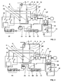
- FIG. 1 An example of a typical water steam cycle of a high efficiency oxy-combustion steam plants is shown in Fig. 1 .
- the plant comprises a triple-pressure series of reheat steam turbines (HP,IP, LP) fed by steam from a boiler (142).
- Exhaust steam from the last low pressure steam turbine (LP) is condensed in a condenser (102) before being polished (104) and pumped via a condenser Extraction pump second stage (103) successively through a series of low pressure heater (106,107,108,109,131), a feed water tank (136) and high pressure heaters (132) before returning to the boiler (142) in a closed loop.
- the heat source for the low and high pressure heaters is typically steam extracted from the low/ intermediate and high pressure steam turbines.
- a coal fired Oxy boiler with oxygen supply system and flue gas CO2 capture system and a steam cycle power plant scheme is provided that integrates major heat generation sources of the systems in order to provide flexible plant operation and improved overall plant thermal efficiency.
- the disclosure is based on the general idea of a novel scheme for thermally incorporating an Air Separation Unit into the condensate system of a coal fired oxy boiler power plant.
- An aspect provides a coal fired Oxy boiler power plant comprising a Rankine steam cycle having a high pressure steam turbine, adapted to expand steam, having an exit, an intermediate pressure steam turbine adapted to expand steam from the high pressure steam turbine, and a low pressure steam turbine adapted to expand steam from the intermediate pressure steam turbine having a steam extraction port.
- a condensate system of the cycle further comprises a condenser adapted to condense steam exhausted from the low pressure steam turbine, a series of low pressure heaters adapted to receive and serially heat condensate from the condenser, a feed water tank configured and arranged to receive condensate from the series of low pressure heaters, and a series of high pressure heaters adapted to receive condensate from the feed water tank.
- the oxy boiler power plant further comprises an Air Separation Unit having a Dryer and a dryer regenerator with a dryer heater wherein an extraction line connects the steam extraction port to the dryer heater.
- a drain line then fluidly connects the regeneration heater to a point of the Rankine steam cycle fluidly between the series of low pressure heater.
- the intermediate pressure steam turbine is a multi-stage intermediate pressure steam turbine and the steam extraction port is configured and arranged to extract steam from an intermediate stage of the intermediate pressure steam turbine.
- an emergency line is connected to the drain line and the condenser.
- a cold reheat line is connected at a first end to the HP steam turbine exit and at a second end to the extraction line .
- the cold reheat line includes a control valve.
- serial units In this context serial means arranged in a series starting from an upstream end as defined by the nominal flow of working fluid through the unit during it's normal operation.
- the coal fired oxy boiler power plant comprises a Rankine steam cycle having a high pressure steam turbine HP adapted to expand steam having an exit 16, an intermediate pressure steam turbine 1 having a steam extraction port 2 adapted to expand steam from the high pressure steam turbine HP, and a low pressure steam turbine LP adapted to expand steam from the intermediate pressure steam turbine 1.
- the oxy boiler power plant further comprises Air Separation Unit having a Dryer with a dryer heater 5 wherein an extraction line 4 connects the steam extraction port 2 to the dryer heater 5.
- a drain line 8 then fluidly connects the dryer heater 5 to the condensate system.
- steam is extracted from an IP steam turbine 1, preferably from an extraction port 2 taken from an intermediate stage of a multi stage IP steam turbine, which is typically used as a heat source for at least one of a series of High Pressure Heaters 22.
- the extraction system is routed via an extraction line 4 to a dryer heater 5 of the Air Separation Unit.
- the dryer heater 5 forms part of the Air Separation Unit dryer regeneration system.
- the steam pressure is controlled, typically to around 19.5 bar by means of an extraction control valve 6 located in the extraction line 4.
- a de-superheater 7 may additional be located in the extraction line 4 upstream of dryer heater 5.
- a cold reheat regneration steam line 18 connects the HP steam turbine exit 16 with the extraction line 4 and is configured with suitable valving to provide an alternate steam source to the IP steam turbine extraction port 2.
- a regeneration steam control valve 19 may be located in the cold reheat regeneration steam line 18.
- the drain line 8 directs condensate formed in the dryer heater 5 to a condensate tank 9 from where it is pumped by a condensate pump 10 back into the condensate system.
- a condensate control valve 13 located in the drain line 8 downstream of the condensate pump 10 provides the condensate tank 9 with level control.
- the condensate is pumped back to the condensate system between the fourth of the series of low pressure heater 12 and the fifth of the series of low pressure heater 20.
- Fig. 2 the condensate is pumped back to the condensate system between the fourth of the series of low pressure heater 12 and the fifth of the series of low pressure heater 20.
- condensate is be pumped back to the condensate system to a point between the fifth of the series of low pressure heaters 20 and the feed water tank 23.
- condensate is be pumped back to the feed water tank 23.
- an emergency line 14 connects the drain line 8 to the condenser 15. This line is normally closed.
Landscapes
- Engineering & Computer Science (AREA)
- Chemical & Material Sciences (AREA)
- Combustion & Propulsion (AREA)
- Mechanical Engineering (AREA)
- General Engineering & Computer Science (AREA)
- Engine Equipment That Uses Special Cycles (AREA)
- Life Sciences & Earth Sciences (AREA)
- Sustainable Development (AREA)
- Sustainable Energy (AREA)
- Physics & Mathematics (AREA)
- Thermal Sciences (AREA)
Abstract
Description
- The present disclosure relates generally to heat integration schemes applied to coal fired oxy boiler power plant, and more specifically to Air Separation Unit heat integration into such plants.
- Coal contributes to a large percentage of the electricity generation in the world today and is expected to maintain its dominant share in the foreseeable future. Nonetheless, significant environmental pressures have led to increased environmental demands requiring not only high efficiency but also reduced emission levels of CO2, SO2, NOx, and mercury to ultra-low levels.
- A particular advantageous plant arrangement is the use of an Oxy-combustion steam plant with CO2 capture. Oxy-combustion systems use oxygen, usually produced in an air separation unit instead of air, for the combustion of the primary fuel. The oxygen is often mixed with an inert gas, such as recirculated flue gas, in order to keep the combustion temperature at a suitable level. Oxy-combustion processes produce flue gas having CO2, water and 02 as its main constituents, the CO2 concentration being typically greater than about 70% by volume. Therefore, CO2 capture from the flue gas of an oxy-combustion process can be done relatively simply in a Gas Processing Unit.
- An example of a typical water steam cycle of a high efficiency oxy-combustion steam plants is shown in
Fig. 1 . The plant comprises a triple-pressure series of reheat steam turbines (HP,IP, LP) fed by steam from a boiler (142). Exhaust steam from the last low pressure steam turbine (LP) is condensed in a condenser (102) before being polished (104) and pumped via a condenser Extraction pump second stage (103) successively through a series of low pressure heater (106,107,108,109,131), a feed water tank (136) and high pressure heaters (132) before returning to the boiler (142) in a closed loop. The heat source for the low and high pressure heaters is typically steam extracted from the low/ intermediate and high pressure steam turbines. - Due to the large benefit in ensuring the highest efficiency cycle there is a continuing need to find ways of better integrating the thermal needs and sinks of the oxy-combustion capture systems within the steam power plant. This requires an optimization of the heat needs and sinks of the capture systems with the plant cycle to ensure no energy is wasted. In particular, these needs take consideration of how to integrate the Air Separation Unit into the condensate cycle.
- A coal fired Oxy boiler with oxygen supply system and flue gas CO2 capture system and a steam cycle power plant scheme is provided that integrates major heat generation sources of the systems in order to provide flexible plant operation and improved overall plant thermal efficiency.
- The disclosure attempts to address this problem by means of the subject matters of the independent claim. Advantageous embodiments are given in the dependent claims.
- The disclosure is based on the general idea of a novel scheme for thermally incorporating an Air Separation Unit into the condensate system of a coal fired oxy boiler power plant.
- An aspect provides a coal fired Oxy boiler power plant comprising a Rankine steam cycle having a high pressure steam turbine, adapted to expand steam, having an exit, an intermediate pressure steam turbine adapted to expand steam from the high pressure steam turbine, and a low pressure steam turbine adapted to expand steam from the intermediate pressure steam turbine having a steam extraction port. A condensate system of the cycle further comprises a condenser adapted to condense steam exhausted from the low pressure steam turbine, a series of low pressure heaters adapted to receive and serially heat condensate from the condenser, a feed water tank configured and arranged to receive condensate from the series of low pressure heaters, and a series of high pressure heaters adapted to receive condensate from the feed water tank.
- The oxy boiler power plant further comprises an Air Separation Unit having a Dryer and a dryer regenerator with a dryer heater wherein an extraction line connects the steam extraction port to the dryer heater. A drain line then fluidly connects the regeneration heater to a point of the Rankine steam cycle fluidly between the series of low pressure heater.
- In an aspect the intermediate pressure steam turbine is a multi-stage intermediate pressure steam turbine and the steam extraction port is configured and arranged to extract steam from an intermediate stage of the intermediate pressure steam turbine.
- In an aspect an emergency line is connected to the drain line and the condenser.
- In an aspect a cold reheat line is connected at a first end to the HP steam turbine exit and at a second end to the extraction line .
- In a further aspect the cold reheat line includes a control valve.
- It is a further object of the invention to overcome or at least ameliorate the disadvantages and shortcomings of the prior art or provide a useful alternative.
- Other aspects and advantages of the present disclosure will become apparent from the following description, taken in connection with the accompanying drawings which by way of example illustrate exemplary embodiments of the present invention
- By way of example, an embodiment of the present disclosure is described more fully hereinafter with reference to the accompanying drawings, in which:
-
Figure 1 is a schematic of a coal fired oxy boiler power plant of the prior art to which exemplary embodiments may be applied; -
Figure 2 is a schematic of the heat integration of an Air Separation Unit drier into a coal fired oxy boiler power plant; -
Figure 3 is a schematic of the heat integration system ofFig. 2 in which an alternate drain line routing into the condensate system is shown; and -
Figure 4 is a schematic of another the heat integration system ofFig. 2 in which a further alternate drain line routing into the condensate system is shown. - Exemplary embodiments of the present disclosure are now described with references to the drawings, wherein like reference numerals are used to refer to like elements throughout. In the following description, for purposes of explanation, numerous specific details are set forth to provide a thorough understanding of the disclosure. However, the present disclosure may be practiced without these specific details, and is not limited to the exemplary embodiments disclosed herein.
- Throughout this specification reference is made to serial units. In this context serial means arranged in a series starting from an upstream end as defined by the nominal flow of working fluid through the unit during it's normal operation.
- In an exemplary embodiment shown in
Fig, 2 , which may be applied to a coal fired oxy boiler power plant shown inFig. 1 , a steam extraction arrangement and condensate return scheme for heat supply to an Air Separation Unit dryer regenerator is provided. As shown inFig. 2 the coal fired oxy boiler power plant comprises a Rankine steam cycle having a high pressure steam turbine HP adapted to expand steam having anexit 16, an intermediate pressure steam turbine 1 having asteam extraction port 2 adapted to expand steam from the high pressure steam turbine HP, and a low pressure steam turbine LP adapted to expand steam from the intermediate pressure steam turbine 1. Acondenser 15, connected to the low pressure steam turbine LP exhaust, condenses exhausted steam as a first element of a condensate system. From thecondenser 15, condensate serially passes through a series oflow pressure heaters low pressure heaters feed water tank 23 is directed into the last element of the condensate system, a series ofHigh Pressure heaters 22. - The oxy boiler power plant further comprises Air Separation Unit having a Dryer with a
dryer heater 5 wherein anextraction line 4 connects thesteam extraction port 2 to thedryer heater 5. Adrain line 8 then fluidly connects thedryer heater 5 to the condensate system. - In an exemplary embodiment shown in
Fig. 2 steam is extracted from an IP steam turbine 1, preferably from anextraction port 2 taken from an intermediate stage of a multi stage IP steam turbine, which is typically used as a heat source for at least one of a series ofHigh Pressure Heaters 22. In an exemplary embodiment shown inFig. 2 , the extraction system is routed via anextraction line 4 to adryer heater 5 of the Air Separation Unit. Thedryer heater 5 forms part of the Air Separation Unit dryer regeneration system. The steam pressure is controlled, typically to around 19.5 bar by means of anextraction control valve 6 located in theextraction line 4. Depending of the temperature of the extraction steam a de-superheater 7 may additional be located in theextraction line 4 upstream ofdryer heater 5. When the Air Separation Unit dryer is based on molecular sieve technology this enables optimum regeneration temperature by ensuring nitrogen heating temperature of around 200°C. For part load or off-design conditions where pressure of extraction steam is inadequate a cold reheatregneration steam line 18, as shown inFig. 2 , is used. This cold reheatregeneration steam line 18 connects the HPsteam turbine exit 16 with theextraction line 4 and is configured with suitable valving to provide an alternate steam source to the IP steamturbine extraction port 2. To ensure adequate use of the cold reheat and pressure control to heat exchanger during an operating mode when the cold reheatregeneration steam line 18 is used to provide steam to the dryer heater 5 a regenerationsteam control valve 19 may be located in the cold reheatregeneration steam line 18. - From the
dryer heater 5 thedrain line 8 directs condensate formed in thedryer heater 5 to acondensate tank 9 from where it is pumped by acondensate pump 10 back into the condensate system. Acondensate control valve 13 located in thedrain line 8 downstream of thecondensate pump 10 provides thecondensate tank 9 with level control. In an exemplary embodiment shown inFig. 2 the condensate is pumped back to the condensate system between the fourth of the series oflow pressure heater 12 and the fifth of the series oflow pressure heater 20. In an alternative or addition exemplary embodiment shown inFig. 3 , condensate is be pumped back to the condensate system to a point between the fifth of the series oflow pressure heaters 20 and thefeed water tank 23. In a further exemplary embodiment shown infig. 4 condensate is be pumped back to thefeed water tank 23. - In an exemplary embodiment shown in
Fig. 2 , anemergency line 14 connects thedrain line 8 to thecondenser 15. This line is normally closed. - Although the disclosure has been herein shown and described in what is conceived to be the most practical exemplary embodiment, it will be appreciated by those skilled in the art that the present disclosure can be embodied in other specific forms without departing from the spirit or essential characteristics thereof. The presently disclosed embodiments are therefore considered in all respects to be illustrative and not restricted. The scope of the disclosure is indicated by the appended claims rather that the foregoing description and all changes that come within the meaning and range and equivalences thereof are intended to be embraced therein.
-
- 1
- IP Turbine
- 2
- Extraction port
- 4
- extraction line
- 5
- dryer heater
- 6
- control valve
- 7
- de-superheater
- 8
- drain line
- 9
- condensate tank
- 10
- condensate pump
- 11
- Low Pressure Heater #3
- 12
- Low
Pressure Heater # 4 - 13
- drain control valve
- 14
- emergency line
- 15
- condenser
- 16
- HP steam turbine exit
- 18
- cold reheat regeneration steam line
- 19
- regeneration steam control valve
- 20
- Low
Pressure heater # 5 - 22
- Serial High Pressure heaters
- 23
- Feed Water Tank
- 24
- Low Pressure Heater #1
- 25
- Low
Pressure Heater # 2 - 101
- Condenser Extraction pump first stage
- 102
- Condenser
- 103
- Condenser Extraction pump second stage
- 104
- Condensate Polishing plant
- 106
- Serial Low Pressure heater #1
- 107
- Serial Low
Pressure heater # 2 - 108
- Serial Low Pressure heater #3
- 109
- Serial Low
Pressure heater # 4 - 131
- Serial Low
Pressure heater # 5 - 132
- Serial High Pressure heaters
- 136
- Feed water tank
- 142
- Boiler
- HP
- High Pressure steam turbine
- IP
- Intermediate pressure steam turbine
- LP
- Low pressure steam turbine
Claims (14)
- A coal fired Oxy boiler power plant comprising a Rankine steam cycle having;
a high pressure steam turbine (HP) adapted to expand steam having an exit (16); an intermediate pressure steam turbine (1) adapted to expand steam from the high pressure steam turbine (HP) and having a steam extraction port (2);
a low pressure steam turbine (LP) adapted to expand steam from the intermediate pressure steam turbine (1); and
a condensate system comprising:a condenser (15) adapted to condense steam exhausted from the low pressure steam turbine (LP):the feed water tank (23),a plurality of serial low pressure heaters (24,25,11,12,20), arranged and numbered in sequential order based on a condensate flow direction, adapted to receive and serially heat condensate from the condenser (15);a feed water tank (23) configured and arranged to receive condensate from the series of low pressure heaters (24,25,11,12,20); anda series of high pressure heaters (22) adapted to receive condensate from
the oxy boiler power plant further comprising an Air Separation Unit having a dryer heater (5) wherein an extraction line (4) connects the steam extraction port (2) to the dryer heater (5), characterised by a drain line (8) fluidly connecting the dryer heater (5) to the condensate system. - The coal fired oxy boiler power plant of claim 1 wherein the drain line (8) connects to the condensate system at a point between a fifth of the series of low pressure heaters (20) and the feed water tank (23).
- The coal fired oxy boiler power plant of claim 1 wherein the drain line (8) connects to the condensate system at the feed water tank (23).
- The coal fired oxy boiler power plant of claim 1 wherein the drain line (8) connects to the condensate system between the series of low pressure heaters (24,25,11,12,20).
- The coal fired oxy boiler power plant of claim 4 wherein the drain line (8) connects to the condensate system at a point between a fourth of the series of low pressure heaters (12) and a fifth of the series of low pressure heaters (20).
- The coal fired oxy boiler power plant of claim 1 wherein the drain line (8) includes a condensate tank (9).
- The coal fired oxy boiler power plant of claim 6 wherein the drain line (8) further includes a condensate pump (10) downstream of the condensate tank (9).
- The coal fired oxy boiler power plant of claim 7 wherein the drain line (8) further includes a condensate control valve (13) downstream of the condensate pump (10) configured to provide the condensate tank with level control.
- The coal fired Oxy boiler power plant of claim 1 further including an extraction control valve (6) located in the extraction line (4).
- The coal fired Oxy boiler power plant of claim 1 further including a desuperheater (7), in the extraction line (4), adapted to remove superheat from steam in the extraction line (4).
- The coal fired Oxy boiler power plant of claim 9 or 10 further comprising a cold reheat regeneration steam line (18) connected at a first end to the exit (16) and at a second end to the extraction line (4).
- The coal fired Oxy boiler power plant of claim 11 wherein the cold reheat regeneration steam line (18) includes a regeneration steam control valve (19).
- The coal fired Oxy boiler power plant of claim 1 wherein the intermediate pressure steam turbine (1) is a multi-stage intermediate pressure steam turbine (1) and the steam extraction port (2) is configured and arranged to extract steam from an intermediate stage of the intermediate pressure steam turbine (1).
- The coal fired Oxy boiler power plant of claim 1 further comprising an emergency line (14) connected to the drain line (8) and the condenser (15).
Priority Applications (8)
| Application Number | Priority Date | Filing Date | Title |
|---|---|---|---|
| EP14290140.4A EP2942496B1 (en) | 2014-05-08 | 2014-05-08 | Oxy boiler power plant with a heat integrated air separation unit |
| AU2015201753A AU2015201753B2 (en) | 2014-05-08 | 2015-04-08 | Oxy boiler power plant with a heat integrated air separation unit |
| US14/682,879 US10001279B2 (en) | 2014-05-08 | 2015-04-09 | Oxy boiler power plant with a heat integrated air separation unit |
| CA2888018A CA2888018C (en) | 2014-05-08 | 2015-04-14 | Oxy boiler power plant with a heat integrated air separation unit |
| TW104112926A TWI645132B (en) | 2014-05-08 | 2015-04-22 | Oxy boiler power plant with a heat integrated air separation unit |
| RU2015116856A RU2670998C2 (en) | 2014-05-08 | 2015-04-30 | Energy installation with oxygen boiler with integrated heat in air intake unit |
| KR1020150063690A KR101878536B1 (en) | 2014-05-08 | 2015-05-07 | Oxy boiler power plant with a heat integrated air separation unit |
| CN201510231440.2A CN105090926A (en) | 2014-05-08 | 2015-05-08 | Oxy boiler power plant with a heat integrated air separation unit |
Applications Claiming Priority (1)
| Application Number | Priority Date | Filing Date | Title |
|---|---|---|---|
| EP14290140.4A EP2942496B1 (en) | 2014-05-08 | 2014-05-08 | Oxy boiler power plant with a heat integrated air separation unit |
Publications (2)
| Publication Number | Publication Date |
|---|---|
| EP2942496A1 true EP2942496A1 (en) | 2015-11-11 |
| EP2942496B1 EP2942496B1 (en) | 2018-10-10 |
Family
ID=50928038
Family Applications (1)
| Application Number | Title | Priority Date | Filing Date |
|---|---|---|---|
| EP14290140.4A Active EP2942496B1 (en) | 2014-05-08 | 2014-05-08 | Oxy boiler power plant with a heat integrated air separation unit |
Country Status (8)
| Country | Link |
|---|---|
| US (1) | US10001279B2 (en) |
| EP (1) | EP2942496B1 (en) |
| KR (1) | KR101878536B1 (en) |
| CN (1) | CN105090926A (en) |
| AU (1) | AU2015201753B2 (en) |
| CA (1) | CA2888018C (en) |
| RU (1) | RU2670998C2 (en) |
| TW (1) | TWI645132B (en) |
Cited By (3)
| Publication number | Priority date | Publication date | Assignee | Title |
|---|---|---|---|---|
| EP3244030A1 (en) * | 2016-05-09 | 2017-11-15 | General Electric Technology GmbH | A steam power plant with power boost through the use of top heater drain reheating |
| CN112833378A (en) * | 2020-12-28 | 2021-05-25 | 东方电气集团东方汽轮机有限公司 | A reheat system that can improve heating capacity |
| CN116291783A (en) * | 2023-02-10 | 2023-06-23 | 华能国际电力股份有限公司 | Coal-fired power generation system and operating method with integrated SSS clutch |
Families Citing this family (2)
| Publication number | Priority date | Publication date | Assignee | Title |
|---|---|---|---|---|
| EP2942497B1 (en) | 2014-05-08 | 2018-10-31 | General Electric Technology GmbH | Oxy boiler power plant oxygen feed system heat integration |
| CN111963411B (en) * | 2020-07-22 | 2022-08-05 | 上海二十冶建设有限公司 | Quick mounting method for skid-mounted air compressor unit of large air separation device |
Citations (4)
| Publication number | Priority date | Publication date | Assignee | Title |
|---|---|---|---|---|
| US3374621A (en) * | 1965-01-26 | 1968-03-26 | Babcock & Wilcox France | Gas turbine auxiliary for steam power plants |
| US5345756A (en) * | 1993-10-20 | 1994-09-13 | Texaco Inc. | Partial oxidation process with production of power |
| WO2006131283A2 (en) * | 2005-06-08 | 2006-12-14 | Man Turbo Ag | Steam generation plant and method for operation and retrofitting of a steam generation plant |
| EP2682569A1 (en) * | 2012-07-05 | 2014-01-08 | Linde Aktiengesellschaft | Method and device for converting energy |
Family Cites Families (45)
| Publication number | Priority date | Publication date | Assignee | Title |
|---|---|---|---|---|
| US2921441A (en) * | 1953-12-17 | 1960-01-19 | Sulzer Ag | Feed water preheating system for steam power plants |
| US2991620A (en) | 1956-06-11 | 1961-07-11 | Nekolny Jaroslav | Desuperheater arrangements for steam turbines |
| US3032999A (en) | 1959-02-13 | 1962-05-08 | Babcock & Wilcox Ltd | Steam turbine power plants |
| CH401096A (en) * | 1963-03-01 | 1965-10-31 | Sulzer Ag | Method and device for feeding an auxiliary turbine in a steam power plant |
| DE1551264A1 (en) * | 1965-03-01 | 1969-06-26 | Steinmueller Gmbh L & C | Cycle for steam power plants |
| US3835650A (en) | 1973-05-03 | 1974-09-17 | Gen Electric | Steam air preheater for a steam boiler system |
| US4069674A (en) | 1977-01-14 | 1978-01-24 | Warren Glenn B | Power plant |
| JPS6088806A (en) | 1983-10-21 | 1985-05-18 | Mitsui Eng & Shipbuild Co Ltd | Waste heat recoverer for internal-combustion engine |
| DE3408937A1 (en) * | 1984-01-31 | 1985-08-08 | BBC Aktiengesellschaft Brown, Boveri & Cie., Baden, Aargau | COMBINED GAS / VAPOR POWER PLANT |
| FI77512C (en) * | 1987-06-18 | 1989-03-10 | Timo Korpela | Procedure for improving the efficiency of a steam power plant process. |
| US4897999A (en) | 1989-02-03 | 1990-02-06 | Varney John W | Steam power plant |
| JP2792777B2 (en) | 1992-01-17 | 1998-09-03 | 関西電力株式会社 | Method for removing carbon dioxide from flue gas |
| JPH062806A (en) | 1992-06-22 | 1994-01-11 | Toshiba Corp | Water supplying and heating device |
| US5765365A (en) * | 1993-03-15 | 1998-06-16 | Mitsubishi Jukogyo Kabushiki Kaisha | Coal gasification power generator |
| US5836162A (en) * | 1996-08-08 | 1998-11-17 | Power Software Associates, Inc. | Feedwater heater drain recycle system |
| RU2152526C1 (en) * | 1999-01-25 | 2000-07-10 | Открытое акционерное общество "Энергетический научно-исследовательский институт им. Г.М. Кржижановского" | Method and power plant for generating electrical energy from shale |
| US6622470B2 (en) * | 2000-05-12 | 2003-09-23 | Clean Energy Systems, Inc. | Semi-closed brayton cycle gas turbine power systems |
| WO2004042200A1 (en) * | 2002-11-08 | 2004-05-21 | Alstom Technology Ltd | Gas turbine power plant and method of operating the same |
| JP3611327B1 (en) | 2003-07-04 | 2005-01-19 | 勝重 山田 | Thermal power plant with reheat / regenerative ranking cycle |
| DE102004059358A1 (en) | 2003-12-01 | 2005-06-23 | Technische Universität Dresden | Method for output of heat to achieve high power plant efficiency entails preheating condensate from turbine's waste steam condenser and then feeding it at higher temperature to additional heat exchangers |
| EP1643100B1 (en) * | 2004-09-29 | 2017-06-28 | Ansaldo Energia IP UK Limited | Power plant and associated operating method |
| JP4959156B2 (en) | 2004-11-29 | 2012-06-20 | 三菱重工業株式会社 | Heat recovery equipment |
| JP2008145007A (en) * | 2006-12-07 | 2008-06-26 | Ihi Corp | Coal burning boiler |
| US7874140B2 (en) * | 2007-06-08 | 2011-01-25 | Foster Wheeler North America Corp. | Method of and power plant for generating power by oxyfuel combustion |
| US8065879B2 (en) * | 2007-07-19 | 2011-11-29 | L'air Liquide Societe Anonyme Pour L'etude Et L'exploitation Des Procedes Georges Claude | Thermal integration of oxygen plants |
| KR100814940B1 (en) * | 2007-09-06 | 2008-03-19 | 한국기계연구원 | Thermal power plant with oxy-fuel burner |
| CA2750780C (en) | 2009-01-28 | 2016-12-13 | Siemens Aktiengesellschaft | Method and device for separating of carbon dioxide from an exhaust gas of a fossil-fired power plant |
| DE102009014185B4 (en) | 2009-03-20 | 2010-12-16 | GMK-Gesellschaft für Motoren und Kraftanlagen mbH | Device for energy conversion according to the ORC principle, ORC system with such a device and method for starting up and / or operating such a device |
| JP5148546B2 (en) | 2009-04-09 | 2013-02-20 | 三菱重工業株式会社 | Heat recovery equipment |
| DE102009056707A1 (en) | 2009-04-18 | 2010-10-21 | Alstom Technology Ltd. | Steam power plant with solar collectors |
| DE102009032537A1 (en) * | 2009-07-10 | 2011-01-13 | Hitachi Power Europe Gmbh | Coal-fired power station with associated CO2 scrubbing and heat recovery |
| US20120174622A1 (en) | 2009-07-13 | 2012-07-12 | Alstom Technology Ltd | System for gas processing |
| EP2290200A1 (en) * | 2009-07-15 | 2011-03-02 | Siemens Aktiengesellschaft | Steam plant assembly with steam turbine unit, process steam consumer and method for operating same with steam turbine unit and process steam consumer |
| CN101761915B (en) * | 2009-12-11 | 2012-07-18 | 华北电力大学(保定) | Combined cycle generation system of high-pressure oxygen-enriched combustion fluidized bed |
| CN102192639A (en) * | 2010-03-09 | 2011-09-21 | 天华化工机械及自动化研究设计院 | Method for reducing coal consumption of coal-fired power plant by adding fluidized bed drying system |
| JP5260585B2 (en) * | 2010-03-12 | 2013-08-14 | 株式会社日立製作所 | Coal-fired power plant and method for operating coal-fired power plant |
| US20110290163A1 (en) | 2010-05-26 | 2011-12-01 | Hisashi Kobayashi | Hybrid oxy-fuel boiler system |
| US20120129112A1 (en) | 2010-11-22 | 2012-05-24 | Foster Wheeler North America Corp. | Method Of And A System For Combusting Fuel In An Oxyfuel Combustion Boiler |
| JP5450540B2 (en) | 2011-09-12 | 2014-03-26 | 株式会社日立製作所 | Boiler heat recovery system with CO2 recovery device |
| EP2584256B1 (en) * | 2011-10-17 | 2015-01-28 | Alstom Technology Ltd | Oxygen preheating in oxyfuel combustion system |
| US20130099508A1 (en) * | 2011-10-19 | 2013-04-25 | Alstom Technology Ltd. | Methods for using a carbon dioxide capture system as an operating reserve |
| CN202343067U (en) * | 2011-10-24 | 2012-07-25 | 宝山钢铁股份有限公司 | PSA (Pressure Swing Adsorption) molecule sieve system of oxygen making machine |
| US20140065559A1 (en) | 2012-09-06 | 2014-03-06 | Alstom Technology Ltd. | Pressurized oxy-combustion power boiler and power plant and method of operating the same |
| US20160033128A1 (en) | 2013-03-21 | 2016-02-04 | Siemens Aktiengesellschaft | Power generation system and method to operate |
| EP2942497B1 (en) * | 2014-05-08 | 2018-10-31 | General Electric Technology GmbH | Oxy boiler power plant oxygen feed system heat integration |
-
2014
- 2014-05-08 EP EP14290140.4A patent/EP2942496B1/en active Active
-
2015
- 2015-04-08 AU AU2015201753A patent/AU2015201753B2/en active Active
- 2015-04-09 US US14/682,879 patent/US10001279B2/en active Active
- 2015-04-14 CA CA2888018A patent/CA2888018C/en active Active
- 2015-04-22 TW TW104112926A patent/TWI645132B/en active
- 2015-04-30 RU RU2015116856A patent/RU2670998C2/en active
- 2015-05-07 KR KR1020150063690A patent/KR101878536B1/en active Active
- 2015-05-08 CN CN201510231440.2A patent/CN105090926A/en active Pending
Patent Citations (4)
| Publication number | Priority date | Publication date | Assignee | Title |
|---|---|---|---|---|
| US3374621A (en) * | 1965-01-26 | 1968-03-26 | Babcock & Wilcox France | Gas turbine auxiliary for steam power plants |
| US5345756A (en) * | 1993-10-20 | 1994-09-13 | Texaco Inc. | Partial oxidation process with production of power |
| WO2006131283A2 (en) * | 2005-06-08 | 2006-12-14 | Man Turbo Ag | Steam generation plant and method for operation and retrofitting of a steam generation plant |
| EP2682569A1 (en) * | 2012-07-05 | 2014-01-08 | Linde Aktiengesellschaft | Method and device for converting energy |
Cited By (3)
| Publication number | Priority date | Publication date | Assignee | Title |
|---|---|---|---|---|
| EP3244030A1 (en) * | 2016-05-09 | 2017-11-15 | General Electric Technology GmbH | A steam power plant with power boost through the use of top heater drain reheating |
| CN112833378A (en) * | 2020-12-28 | 2021-05-25 | 东方电气集团东方汽轮机有限公司 | A reheat system that can improve heating capacity |
| CN116291783A (en) * | 2023-02-10 | 2023-06-23 | 华能国际电力股份有限公司 | Coal-fired power generation system and operating method with integrated SSS clutch |
Also Published As
| Publication number | Publication date |
|---|---|
| CA2888018A1 (en) | 2015-11-08 |
| RU2015116856A (en) | 2016-11-20 |
| AU2015201753B2 (en) | 2018-07-12 |
| KR101878536B1 (en) | 2018-07-13 |
| CA2888018C (en) | 2018-11-27 |
| KR20150128591A (en) | 2015-11-18 |
| AU2015201753A1 (en) | 2015-11-26 |
| US10001279B2 (en) | 2018-06-19 |
| RU2670998C2 (en) | 2018-10-29 |
| EP2942496B1 (en) | 2018-10-10 |
| TW201604491A (en) | 2016-02-01 |
| CN105090926A (en) | 2015-11-25 |
| US20150330628A1 (en) | 2015-11-19 |
| RU2015116856A3 (en) | 2018-09-04 |
| TWI645132B (en) | 2018-12-21 |
Similar Documents
| Publication | Publication Date | Title |
|---|---|---|
| US10006634B2 (en) | Coal fired oxy plant with air separation unit including parallel coupled heat exchanger | |
| CA2890561C (en) | Oxy boiler power plant oxygen feed system heat integration | |
| US9915424B2 (en) | Coal fired Oxy plant with Flue Gas Heat Recovery | |
| CA2888018C (en) | Oxy boiler power plant with a heat integrated air separation unit |
Legal Events
| Date | Code | Title | Description |
|---|---|---|---|
| PUAI | Public reference made under article 153(3) epc to a published international application that has entered the european phase |
Free format text: ORIGINAL CODE: 0009012 |
|
| 17P | Request for examination filed |
Effective date: 20140516 |
|
| AK | Designated contracting states |
Kind code of ref document: A1 Designated state(s): AL AT BE BG CH CY CZ DE DK EE ES FI FR GB GR HR HU IE IS IT LI LT LU LV MC MK MT NL NO PL PT RO RS SE SI SK SM TR |
|
| AX | Request for extension of the european patent |
Extension state: BA ME |
|
| RAP1 | Party data changed (applicant data changed or rights of an application transferred) |
Owner name: GENERAL ELECTRIC TECHNOLOGY GMBH |
|
| GRAP | Despatch of communication of intention to grant a patent |
Free format text: ORIGINAL CODE: EPIDOSNIGR1 |
|
| STAA | Information on the status of an ep patent application or granted ep patent |
Free format text: STATUS: GRANT OF PATENT IS INTENDED |
|
| RIC1 | Information provided on ipc code assigned before grant |
Ipc: F01K 13/00 20060101ALI20180420BHEP Ipc: F01K 7/16 20060101ALI20180420BHEP Ipc: F01K 17/06 20060101ALI20180420BHEP Ipc: F23L 7/00 20060101ALI20180420BHEP Ipc: F01K 9/02 20060101ALI20180420BHEP Ipc: F01K 7/40 20060101AFI20180420BHEP |
|
| INTG | Intention to grant announced |
Effective date: 20180516 |
|
| GRAS | Grant fee paid |
Free format text: ORIGINAL CODE: EPIDOSNIGR3 |
|
| GRAA | (expected) grant |
Free format text: ORIGINAL CODE: 0009210 |
|
| STAA | Information on the status of an ep patent application or granted ep patent |
Free format text: STATUS: THE PATENT HAS BEEN GRANTED |
|
| AK | Designated contracting states |
Kind code of ref document: B1 Designated state(s): AL AT BE BG CH CY CZ DE DK EE ES FI FR GB GR HR HU IE IS IT LI LT LU LV MC MK MT NL NO PL PT RO RS SE SI SK SM TR |
|
| REG | Reference to a national code |
Ref country code: GB Ref legal event code: FG4D |
|
| REG | Reference to a national code |
Ref country code: CH Ref legal event code: EP Ref country code: AT Ref legal event code: REF Ref document number: 1051495 Country of ref document: AT Kind code of ref document: T Effective date: 20181015 |
|
| REG | Reference to a national code |
Ref country code: IE Ref legal event code: FG4D |
|
| REG | Reference to a national code |
Ref country code: DE Ref legal event code: R096 Ref document number: 602014033714 Country of ref document: DE |
|
| REG | Reference to a national code |
Ref country code: NO Ref legal event code: T2 Effective date: 20181010 |
|
| REG | Reference to a national code |
Ref country code: NL Ref legal event code: MP Effective date: 20181010 |
|
| REG | Reference to a national code |
Ref country code: LT Ref legal event code: MG4D |
|
| REG | Reference to a national code |
Ref country code: AT Ref legal event code: MK05 Ref document number: 1051495 Country of ref document: AT Kind code of ref document: T Effective date: 20181010 |
|
| PG25 | Lapsed in a contracting state [announced via postgrant information from national office to epo] |
Ref country code: NL Free format text: LAPSE BECAUSE OF FAILURE TO SUBMIT A TRANSLATION OF THE DESCRIPTION OR TO PAY THE FEE WITHIN THE PRESCRIBED TIME-LIMIT Effective date: 20181010 |
|
| PG25 | Lapsed in a contracting state [announced via postgrant information from national office to epo] |
Ref country code: BG Free format text: LAPSE BECAUSE OF FAILURE TO SUBMIT A TRANSLATION OF THE DESCRIPTION OR TO PAY THE FEE WITHIN THE PRESCRIBED TIME-LIMIT Effective date: 20190110 Ref country code: LT Free format text: LAPSE BECAUSE OF FAILURE TO SUBMIT A TRANSLATION OF THE DESCRIPTION OR TO PAY THE FEE WITHIN THE PRESCRIBED TIME-LIMIT Effective date: 20181010 Ref country code: ES Free format text: LAPSE BECAUSE OF FAILURE TO SUBMIT A TRANSLATION OF THE DESCRIPTION OR TO PAY THE FEE WITHIN THE PRESCRIBED TIME-LIMIT Effective date: 20181010 Ref country code: IS Free format text: LAPSE BECAUSE OF FAILURE TO SUBMIT A TRANSLATION OF THE DESCRIPTION OR TO PAY THE FEE WITHIN THE PRESCRIBED TIME-LIMIT Effective date: 20190210 Ref country code: LV Free format text: LAPSE BECAUSE OF FAILURE TO SUBMIT A TRANSLATION OF THE DESCRIPTION OR TO PAY THE FEE WITHIN THE PRESCRIBED TIME-LIMIT Effective date: 20181010 Ref country code: AT Free format text: LAPSE BECAUSE OF FAILURE TO SUBMIT A TRANSLATION OF THE DESCRIPTION OR TO PAY THE FEE WITHIN THE PRESCRIBED TIME-LIMIT Effective date: 20181010 Ref country code: HR Free format text: LAPSE BECAUSE OF FAILURE TO SUBMIT A TRANSLATION OF THE DESCRIPTION OR TO PAY THE FEE WITHIN THE PRESCRIBED TIME-LIMIT Effective date: 20181010 Ref country code: PL Free format text: LAPSE BECAUSE OF FAILURE TO SUBMIT A TRANSLATION OF THE DESCRIPTION OR TO PAY THE FEE WITHIN THE PRESCRIBED TIME-LIMIT Effective date: 20181010 Ref country code: FI Free format text: LAPSE BECAUSE OF FAILURE TO SUBMIT A TRANSLATION OF THE DESCRIPTION OR TO PAY THE FEE WITHIN THE PRESCRIBED TIME-LIMIT Effective date: 20181010 |
|
| PG25 | Lapsed in a contracting state [announced via postgrant information from national office to epo] |
Ref country code: AL Free format text: LAPSE BECAUSE OF FAILURE TO SUBMIT A TRANSLATION OF THE DESCRIPTION OR TO PAY THE FEE WITHIN THE PRESCRIBED TIME-LIMIT Effective date: 20181010 Ref country code: SE Free format text: LAPSE BECAUSE OF FAILURE TO SUBMIT A TRANSLATION OF THE DESCRIPTION OR TO PAY THE FEE WITHIN THE PRESCRIBED TIME-LIMIT Effective date: 20181010 Ref country code: GR Free format text: LAPSE BECAUSE OF FAILURE TO SUBMIT A TRANSLATION OF THE DESCRIPTION OR TO PAY THE FEE WITHIN THE PRESCRIBED TIME-LIMIT Effective date: 20190111 Ref country code: RS Free format text: LAPSE BECAUSE OF FAILURE TO SUBMIT A TRANSLATION OF THE DESCRIPTION OR TO PAY THE FEE WITHIN THE PRESCRIBED TIME-LIMIT Effective date: 20181010 Ref country code: PT Free format text: LAPSE BECAUSE OF FAILURE TO SUBMIT A TRANSLATION OF THE DESCRIPTION OR TO PAY THE FEE WITHIN THE PRESCRIBED TIME-LIMIT Effective date: 20190210 |
|
| REG | Reference to a national code |
Ref country code: DE Ref legal event code: R097 Ref document number: 602014033714 Country of ref document: DE |
|
| PG25 | Lapsed in a contracting state [announced via postgrant information from national office to epo] |
Ref country code: CZ Free format text: LAPSE BECAUSE OF FAILURE TO SUBMIT A TRANSLATION OF THE DESCRIPTION OR TO PAY THE FEE WITHIN THE PRESCRIBED TIME-LIMIT Effective date: 20181010 Ref country code: IT Free format text: LAPSE BECAUSE OF FAILURE TO SUBMIT A TRANSLATION OF THE DESCRIPTION OR TO PAY THE FEE WITHIN THE PRESCRIBED TIME-LIMIT Effective date: 20181010 Ref country code: DK Free format text: LAPSE BECAUSE OF FAILURE TO SUBMIT A TRANSLATION OF THE DESCRIPTION OR TO PAY THE FEE WITHIN THE PRESCRIBED TIME-LIMIT Effective date: 20181010 |
|
| PLBE | No opposition filed within time limit |
Free format text: ORIGINAL CODE: 0009261 |
|
| STAA | Information on the status of an ep patent application or granted ep patent |
Free format text: STATUS: NO OPPOSITION FILED WITHIN TIME LIMIT |
|
| PG25 | Lapsed in a contracting state [announced via postgrant information from national office to epo] |
Ref country code: EE Free format text: LAPSE BECAUSE OF FAILURE TO SUBMIT A TRANSLATION OF THE DESCRIPTION OR TO PAY THE FEE WITHIN THE PRESCRIBED TIME-LIMIT Effective date: 20181010 Ref country code: SM Free format text: LAPSE BECAUSE OF FAILURE TO SUBMIT A TRANSLATION OF THE DESCRIPTION OR TO PAY THE FEE WITHIN THE PRESCRIBED TIME-LIMIT Effective date: 20181010 Ref country code: RO Free format text: LAPSE BECAUSE OF FAILURE TO SUBMIT A TRANSLATION OF THE DESCRIPTION OR TO PAY THE FEE WITHIN THE PRESCRIBED TIME-LIMIT Effective date: 20181010 Ref country code: SK Free format text: LAPSE BECAUSE OF FAILURE TO SUBMIT A TRANSLATION OF THE DESCRIPTION OR TO PAY THE FEE WITHIN THE PRESCRIBED TIME-LIMIT Effective date: 20181010 |
|
| 26N | No opposition filed |
Effective date: 20190711 |
|
| PG25 | Lapsed in a contracting state [announced via postgrant information from national office to epo] |
Ref country code: SI Free format text: LAPSE BECAUSE OF FAILURE TO SUBMIT A TRANSLATION OF THE DESCRIPTION OR TO PAY THE FEE WITHIN THE PRESCRIBED TIME-LIMIT Effective date: 20181010 |
|
| REG | Reference to a national code |
Ref country code: CH Ref legal event code: PL |
|
| PG25 | Lapsed in a contracting state [announced via postgrant information from national office to epo] |
Ref country code: CH Free format text: LAPSE BECAUSE OF NON-PAYMENT OF DUE FEES Effective date: 20190531 Ref country code: LI Free format text: LAPSE BECAUSE OF NON-PAYMENT OF DUE FEES Effective date: 20190531 Ref country code: MC Free format text: LAPSE BECAUSE OF FAILURE TO SUBMIT A TRANSLATION OF THE DESCRIPTION OR TO PAY THE FEE WITHIN THE PRESCRIBED TIME-LIMIT Effective date: 20181010 |
|
| REG | Reference to a national code |
Ref country code: BE Ref legal event code: MM Effective date: 20190531 |
|
| PG25 | Lapsed in a contracting state [announced via postgrant information from national office to epo] |
Ref country code: LU Free format text: LAPSE BECAUSE OF NON-PAYMENT OF DUE FEES Effective date: 20190508 |
|
| PG25 | Lapsed in a contracting state [announced via postgrant information from national office to epo] |
Ref country code: TR Free format text: LAPSE BECAUSE OF FAILURE TO SUBMIT A TRANSLATION OF THE DESCRIPTION OR TO PAY THE FEE WITHIN THE PRESCRIBED TIME-LIMIT Effective date: 20181010 |
|
| PG25 | Lapsed in a contracting state [announced via postgrant information from national office to epo] |
Ref country code: IE Free format text: LAPSE BECAUSE OF NON-PAYMENT OF DUE FEES Effective date: 20190508 |
|
| PG25 | Lapsed in a contracting state [announced via postgrant information from national office to epo] |
Ref country code: BE Free format text: LAPSE BECAUSE OF NON-PAYMENT OF DUE FEES Effective date: 20190531 |
|
| PG25 | Lapsed in a contracting state [announced via postgrant information from national office to epo] |
Ref country code: FR Free format text: LAPSE BECAUSE OF NON-PAYMENT OF DUE FEES Effective date: 20190531 |
|
| PG25 | Lapsed in a contracting state [announced via postgrant information from national office to epo] |
Ref country code: CY Free format text: LAPSE BECAUSE OF FAILURE TO SUBMIT A TRANSLATION OF THE DESCRIPTION OR TO PAY THE FEE WITHIN THE PRESCRIBED TIME-LIMIT Effective date: 20181010 |
|
| PG25 | Lapsed in a contracting state [announced via postgrant information from national office to epo] |
Ref country code: MT Free format text: LAPSE BECAUSE OF FAILURE TO SUBMIT A TRANSLATION OF THE DESCRIPTION OR TO PAY THE FEE WITHIN THE PRESCRIBED TIME-LIMIT Effective date: 20181010 Ref country code: HU Free format text: LAPSE BECAUSE OF FAILURE TO SUBMIT A TRANSLATION OF THE DESCRIPTION OR TO PAY THE FEE WITHIN THE PRESCRIBED TIME-LIMIT; INVALID AB INITIO Effective date: 20140508 |
|
| PG25 | Lapsed in a contracting state [announced via postgrant information from national office to epo] |
Ref country code: MK Free format text: LAPSE BECAUSE OF FAILURE TO SUBMIT A TRANSLATION OF THE DESCRIPTION OR TO PAY THE FEE WITHIN THE PRESCRIBED TIME-LIMIT Effective date: 20181010 |
|
| PGFP | Annual fee paid to national office [announced via postgrant information from national office to epo] |
Ref country code: DE Payment date: 20250423 Year of fee payment: 12 |
|
| PGFP | Annual fee paid to national office [announced via postgrant information from national office to epo] |
Ref country code: GB Payment date: 20250423 Year of fee payment: 12 |
|
| PGFP | Annual fee paid to national office [announced via postgrant information from national office to epo] |
Ref country code: NO Payment date: 20250424 Year of fee payment: 12 |