EP2942153A1 - Method and device for grinding metal annular member - Google Patents
Method and device for grinding metal annular member Download PDFInfo
- Publication number
- EP2942153A1 EP2942153A1 EP13869417.9A EP13869417A EP2942153A1 EP 2942153 A1 EP2942153 A1 EP 2942153A1 EP 13869417 A EP13869417 A EP 13869417A EP 2942153 A1 EP2942153 A1 EP 2942153A1
- Authority
- EP
- European Patent Office
- Prior art keywords
- processed object
- grinding
- dimension
- radial direction
- change
- Prior art date
- Legal status (The legal status is an assumption and is not a legal conclusion. Google has not performed a legal analysis and makes no representation as to the accuracy of the status listed.)
- Granted
Links
Images




Classifications
-
- B—PERFORMING OPERATIONS; TRANSPORTING
- B24—GRINDING; POLISHING
- B24B—MACHINES, DEVICES, OR PROCESSES FOR GRINDING OR POLISHING; DRESSING OR CONDITIONING OF ABRADING SURFACES; FEEDING OF GRINDING, POLISHING, OR LAPPING AGENTS
- B24B5/00—Machines or devices designed for grinding surfaces of revolution on work, including those which also grind adjacent plane surfaces; Accessories therefor
- B24B5/35—Accessories
- B24B5/355—Feeding means
-
- B—PERFORMING OPERATIONS; TRANSPORTING
- B24—GRINDING; POLISHING
- B24B—MACHINES, DEVICES, OR PROCESSES FOR GRINDING OR POLISHING; DRESSING OR CONDITIONING OF ABRADING SURFACES; FEEDING OF GRINDING, POLISHING, OR LAPPING AGENTS
- B24B49/00—Measuring or gauging equipment for controlling the feed movement of the grinding tool or work; Arrangements of indicating or measuring equipment, e.g. for indicating the start of the grinding operation
- B24B49/02—Measuring or gauging equipment for controlling the feed movement of the grinding tool or work; Arrangements of indicating or measuring equipment, e.g. for indicating the start of the grinding operation according to the instantaneous size and required size of the workpiece acted upon, the measuring or gauging being continuous or intermittent
- B24B49/04—Measuring or gauging equipment for controlling the feed movement of the grinding tool or work; Arrangements of indicating or measuring equipment, e.g. for indicating the start of the grinding operation according to the instantaneous size and required size of the workpiece acted upon, the measuring or gauging being continuous or intermittent involving measurement of the workpiece at the place of grinding during grinding operation
-
- B—PERFORMING OPERATIONS; TRANSPORTING
- B24—GRINDING; POLISHING
- B24B—MACHINES, DEVICES, OR PROCESSES FOR GRINDING OR POLISHING; DRESSING OR CONDITIONING OF ABRADING SURFACES; FEEDING OF GRINDING, POLISHING, OR LAPPING AGENTS
- B24B5/00—Machines or devices designed for grinding surfaces of revolution on work, including those which also grind adjacent plane surfaces; Accessories therefor
- B24B5/02—Machines or devices designed for grinding surfaces of revolution on work, including those which also grind adjacent plane surfaces; Accessories therefor involving centres or chucks for holding work
- B24B5/04—Machines or devices designed for grinding surfaces of revolution on work, including those which also grind adjacent plane surfaces; Accessories therefor involving centres or chucks for holding work for grinding cylindrical surfaces externally
-
- B—PERFORMING OPERATIONS; TRANSPORTING
- B24—GRINDING; POLISHING
- B24B—MACHINES, DEVICES, OR PROCESSES FOR GRINDING OR POLISHING; DRESSING OR CONDITIONING OF ABRADING SURFACES; FEEDING OF GRINDING, POLISHING, OR LAPPING AGENTS
- B24B5/00—Machines or devices designed for grinding surfaces of revolution on work, including those which also grind adjacent plane surfaces; Accessories therefor
- B24B5/35—Accessories
-
- G—PHYSICS
- G05—CONTROLLING; REGULATING
- G05B—CONTROL OR REGULATING SYSTEMS IN GENERAL; FUNCTIONAL ELEMENTS OF SUCH SYSTEMS; MONITORING OR TESTING ARRANGEMENTS FOR SUCH SYSTEMS OR ELEMENTS
- G05B19/00—Program-control systems
- G05B19/02—Program-control systems electric
- G05B19/18—Numerical control [NC], i.e. automatically operating machines, in particular machine tools, e.g. in a manufacturing environment, so as to execute positioning, movement or co-ordinated operations by means of program data in numerical form
- G05B19/182—Numerical control [NC], i.e. automatically operating machines, in particular machine tools, e.g. in a manufacturing environment, so as to execute positioning, movement or co-ordinated operations by means of program data in numerical form characterised by the machine tool function, e.g. thread cutting, cam making, tool direction control
-
- G—PHYSICS
- G05—CONTROLLING; REGULATING
- G05B—CONTROL OR REGULATING SYSTEMS IN GENERAL; FUNCTIONAL ELEMENTS OF SUCH SYSTEMS; MONITORING OR TESTING ARRANGEMENTS FOR SUCH SYSTEMS OR ELEMENTS
- G05B2219/00—Program-control systems
- G05B2219/30—Nc systems
- G05B2219/45—Nc applications
- G05B2219/45161—Grinding machine
Definitions
- the present invention relates to a method and device that uses a rotating grindstone for grinding the circumferential surface of a metal annular member that is being processed.
- a grinding process is performed on the circumferential surfaces of metal annular members such as the raceway surfaces of race members of a radial rolling bearing, or cylindrical shaped fitting surfaces in order to improve the surface precision or surface roughness. As illustrated in FIG.1A and FIG. 1B , this grinding process is performed using a grinding device.
- the grinding device normally comprises: a rotating drive shaft (not illustrated in the figures); a backing plate 2 that is fastened to the tip-end section of the rotating drive shaft, and that magnetically affixes an annular processed object (work) 1 on the end surface thereof; at least two shoes 3 for making it possible to position the processed object in the radial direction; a rotating grindstone 4 that grinds the outer-circumferential surface or inner-circumferential surface of the processed object 1; a contact sensor or non-contact sensor (not illustrated in the figures) that comprises at least two gauge heads 5 and that measures the outer diameter D of the processed object 1; and a controller (not illustrated in the figures) for controlling the feed speed of the grindstone 4 based on the obtained measurement results.
- the grinding process is performed in a state in which the processed object 1 is positioned in the radial direction by supporting and fastening the processed object 1 to the backing plate 2, and bringing the shoes 3 into sliding contact with the outer-circumferential surface of the processed object 1.
- the feed speed of the grindstone 4 is suitably controlled by measuring the outer diameter D at two locations on opposite sides in the radial direction of the outer-circumferential surface of the processed object 1 that is being ground in process by the sensor and feeding the measurement results back to the controller.
- the grinding of a metal annular member is performed in the order of rough grinding, finish grinding and spark out.
- the feed speed of the grindstone 4 feed amount/time
- the feed speed of the grindstone 4 is set to "0"
- spark out begins. Spark out is a process of grinding the circumferential surface of the processed object 1 in a state in which the feed speed of the grindstone 4 is "0", and by only the circumferential surface of the processed object 1 pressing against the surface of the grindstone 4 due to elastic restoration of the processed object 1.
- the grindstone 4 is caused to displace in a direction away from the outer-circumferential surface of the processed object 1, and grinding ends.
- the processed object 1 is elastically deformed from the state illustrated in FIG. 7A to an elliptical shape as exaggeratedly illustrated in FIG. 7B by pressing the grindstone 4 against the processed object 1 in the rough grinding process, and the processed object 1 is elastically restored in the processing after that (finish grinding and spark out).
- the elastic deformation of the processed object 1 becomes more prominent the lower the rigidity is of the processed object 1.
- the installation positions of the gauge heads 5 are normally shifted about 90° in the circumferential direction from the contact position between the processed object 1 and the grindstone 4.
- the outer diameter D of the processed object 1 that is measured by the gauge heads 5 becomes larger than the outer diameter in the free state (state in which the outer-circumferential surface is not pressed by the shoes 3 and grindstone 4, and elastic deformation is released).
- the amount of grinding becomes excessive, and the outer diameter in the free state of the processed object 1 that is obtained becomes smaller than the target dimension.
- the feed speed of the grindstone 4 can be considered to make the feed speed of the grindstone 4 "0" in a state in which the outer diameter D of the processed object 1 that is measured by the gauge heads 5 is larger than the original target dimension and perform spark out for a specified amount of time such that the outer diameter in the free state of the processed object 1 may be made as a target dimension.
- the amount of elastic deformation of the processed object 1 fluctuates due to the cutting ability of the grindstone 4 and the like. In other words, as the cutting ability of the grindstone 4 degrades, the amount of elastic deformation of the processed object 1 becomes larger, and the better the cutting ability of the grindstone 4 is, the smaller the amount of elastic deformation of the processed object 1 becomes.
- the cutting ability of the grindstone 4 is better than a set value, the amount of elastic restoration of the processed object 1 during spark out becomes less than a set value, and the amount of grinding of the outer-circumferential surface of the processed object 1 by spark out becomes less than a set value, so the outer diameter D in the state after grinding of the processed object 1 is complete becomes larger than the target dimension.
- the outer diameter D at the end of spark out of the processed object 1 is larger than the target dimension, it is feasible to make the outer diameter of the processed object 1 the target dimension by further performing step-feed grinding of the processed object 1 as illustrated in FIG. 8 in which the feed speed of the grindstone 4 and the amount of cutting are very small.
- step-feed grinding of the processed object 1 as illustrated in FIG. 8 in which the feed speed of the grindstone 4 and the amount of cutting are very small.
- the amount of time that spark out is performed is set, based on the set value of the cutting ability of the grindstone 4, to an amount of time sufficient for sparks and grinding noise from the area of contact between the outer-circumferential surface of the processed object 1 and the surface of the grindstone 4 to stop, and for the outer-circumferential surface of the processed object 1 to become smooth. Therefore, when the cutting ability of the grindstone 4 is better than a set value, the amount of time that spark out is performed and the overall amount of time that grinding is performed becomes unnecessarily long.
- JP 2000-343425 (A ) discloses a method of learning the starting point for spark out (timing at which grinding changes from finish grinding to spark out) from the amount of change in the outer diameter per one rotation of the processed object 1 at the end of spark out, and then adjusting the starting point of spark out in the next grinding after this learning is complete.
- JP 2012-143843 (A ) discloses a method of adjusting the feed speed of the grindstone in the next grinding process that is performed after that learning based on the amount of time required for making the outer diameter of the processed object the target dimension.
- the object of the present invention is to provide a grinding method that is able to prevent variation in the outer-diameter dimension of a processed object at the completion of spark out, and prevent the amount of time that grinding is performed from becoming unnecessarily long, regardless of change in the amount of elastic deformation of the processed object due to change in the cutting ability of the grindstone and the like.
- the present invention relates to a method for grinding a metal annular member, the method comprising a step of grinding a circumferential surface of a metal annular processed object using a rotating grindstone while measuring a dimension in a radial direction of the processed object in process, the grinding being performed so that after a rough grinding performed at a specified feed speed of the rotating grindstone, a finish grinding is performed by slowing the feed speed of the rotating grindstone, and then a spark out is performed by making the feed speed of the rotating grindstone '0'.
- a condition for at least one of starting the spark out (switching from the finish grinding to the spark out) or ending the spark out is determined based on a rate of change of the dimension in the radial direction of the processed object, which is an amount of change in the dimension in the radial direction per unit time or per one rotation of the processed object.
- a first threshold value for the rate of change of the dimension in the radial direction of the processed object is determined for each of a plurality of different preset target values for the dimension in the radial direction of the processed object.
- the spark out starts (grinding switches from the finish grinding to the spark out) under a condition that an absolute value of the rate of change of the dimension in the radial direction of the processed object becomes greater than the first threshold value that corresponds to the one target value.
- the spark out ends when during the spark out an absolute value of the rate of change of the dimension in the radial direction of the processed object becomes less than a second preset threshold value.
- the present invention relates to a device for grinding a metal annular member.
- the device for grinding a metal annular member of the present invention comprises: a means for supporting and fastening a processed object and rotating the processed object; a means for positioning the processed object in a radial direction; a rotating grindstone grinding a circumferential surface of the processed object; a sensor measuring an outer diameter of the processed object; and a controller controlling a rotation of the rotating grindstone based on a measurement result measured by the sensor; the device executing the method for grinding a metal annular member of the present invention.
- the controller determines at least one of a timing for starting the spark out or a timing for ending the spark out based on the rate of change of the dimension in the radial direction of the processed object.
- the controller compares the absolute value of the rate of change of the dimension in the radial direction of the processed object with one of first threshold values for the rate of change of the dimension in the radial direction of the processed object that are determined for the plurality of different preset target values for the dimension in the radial direction of the processed object, the one first threshold value corresponding to one of the target values at a particular time, and starts the spark out under a condition that the absolute value of the rate of change of the dimension in the radial direction of the processed object is greater than the one first threshold value corresponding to the one target value at the particular time.
- the controller ends the spark out when the absolute value of the rate of change of the dimension in the radial direction of the processed object becomes less than a second preset threshold value.
- the condition of at least one of the start of spark out or the end of spark out in the grinding process is set based on the rate of change of the dimension in the radial direction, which is the amount of change of the dimension in the radial direction of the processed object per unit time or per one rotation of the processed object. Therefore, it is possible to perform spark out while taking into consideration the amount of elastic deformation of the processed object.
- FIG. 1A to FIG. 6 illustrate an example of an embodiment of the present invention.
- a feature of this example is that, by suitably setting the timing at which spark out begins (change from finish grinding to spark out) and ends in the grinding process, the outer diameter D of a processed object (work) 1 is suppressed from varying in the completed state of processing, and the time required for grinding is prevented from becoming unnecessarily long regardless of change in the amount of elastic deformation of the processed object 1 due to a change in the cutting ability of the grindstone 4.
- the grinding device of this example is basically the same as the construction of a conventional grinding device and comprises: a rotating drive shaft (not illustrated in the figure) that supports and secures a processed object and causes that processed object to rotate; a backing plate 2 that is fastened to the tip end of this rotating drive shaft and magnetically affixes an annular processed object (work) 1 to the end surface thereof; two shoes 3 that position the processed object 1 in the radial direction; a rotating grindstone 4 that grinds the outer-circumferential surface of the processed object 1; a sensor (not illustrated in the figure) that comprises at least two gauge heads 5 and measures the outer diameter D of the processed object 1; and a controller (not illustrated in the figure) that controls the rotation of the rotating grindstone 4 based on the measurement results measured by the sensor.
- a means for supporting, securing and rotating the processed object 1 it is possible to use a combination of a rotating drive shaft, and a known chuck device such as a mechanical chuck or magnetic chuck that can be attached to the rotating drive shaft, and that can support and secure the processed object 1 on the rotating drive shaft.
- a means for positioning the processed object 1 in the radial direction it is also possible to use rollers and the like, or use a combination of an arbitrary number of rollers and shoes.
- a sensor for measuring the outer diameter D of the processed object 1 it is possible to use a contact displacement sensor that uses contacts as the gauge heads 5, or it is possible to use a non-contact sensor that uses laser lights as the gauge heads 5.
- the method of grinding in this example is the same as the basic processing in the conventional method.
- the outer-circumferential surface of the processed object 1 is grinded using a rotating grindstone 4 while measuring the dimension in the radial direction of the processed object 1 in process, and the grinding process is performed on the outer-circumferential surface of the processed object 1 in the order: a rough grinding, a finish grinding and a spark out.
- the outer diameter D of the processed object 1 can be measured in process by two gauge heads 5, and the controller switches from the rough grinding to the finish grinding when the outer diameter D of the processed object 1 that is measured by the gauge heads 5 reaches a specified value.
- a feature of the controller in this example is that the controller determines both the start and end of spark out based on the rate of change v ( ⁇ m/s), which is the amount of change per unit time of the outer diameter D of the processed object 1 that is measured by the gauge heads 5. More specifically, in order for the controller to determine the timing of the start of spark out (timing at which grinding is switched from the finish grinding to the spark out), plural (for example, 5 to 6) target values Di are set in advance for the outer diameter D of the processed object 1. When the number of target values is 5, the value i is a natural number that is no less than 1 and no greater than 5 (1 ⁇ i ⁇ 5), and the target values Di are set so that D 1 > D 2 > ... > D 5 .
- first threshold values v i are set for the rate of change of the outer diameter D of the processed object 1 for each of these target values Di.
- Target values Di and first threshold values v i such as these are found by testing or calculation in advance according to the shape and material of the processed object 1. In other words, the target values Di and the first threshold values v i change according to the shape and material of the processed object 1.
- the method by which the controller determines the timing for starting spark out based on the rate of change v of the outer diameter D of the processed object 1 will be explained with reference to the flowchart in FIG. 3 .
- the work illustrated in this flowchart is executed by the controller from the start of finish grinding to the start of spark out, or until the end of grinding when suitable timing for starting spark out cannot be determined.
- step 1 the controller determines whether or not the outer diameter D of the processed object 1 that is measured by the gauge heads 5 at that instant is the same as the target value D i (whether or not the outer diameter D is within a specified range with the target value D i being the center value).
- processing advances to step 2, and the controller determines whether or not the outer diameter D is less than the target value D i (D ⁇ D i ).
- step 3 when the outer diameter D is less than the target value D i (D ⁇ D i ), processing advances to step 3, and the value i is increased by 1, after which processing advances to step 4.
- step 2 and step 3 when the outer diameter D is less than the target value D i (D ⁇ D i ), the outer diameter does not become equal to the target value D i even when finish grinding is continued after that, so this work is a process for making the target value Di that is used for comparison with the outer diameter D a value D i + 1 , which is value that is one step smaller.
- step 4 the controller determines whether or not the value i is equal to or less than the number (total number) n of target values Di.
- the controller determines whether or not the value i is equal to or less than the number (total number) n of target values Di.
- the controller issues a warning from a display such as a buzzer or warning light.
- a warning from a display such as a buzzer or warning light.
- step 4 and step 5 are performed in the procedure from step 1 to step 6 described later, and when suitable timing for staring spark out could not be determined by comparing the outer diameter D of the processed object 1 with the minimum target value D n of the target values D i , this procedure becomes a procedure for ending grinding in error (exception process).
- step 7 the controller starts spark out (the feed speed of the grindstone 4 is made "0") and ends the procedure for determined the timing for starting spark out.
- the absolute value of the rate of change v is equal to or less than the first threshold value vi (
- processing advances to the procedure from step 3 to step 4, after which the controller performs processing according to the procedure described above.
- the controller determines the timing for ending spark out according to the procedure illustrated in FIG. 4 .
- the work illustrated in the flowchart in FIG. 4 is executed by the controller from after the start of spark out until spark out ends.
- the controller determines whether or not the absolute value of the rate of change v is less than a second preset threshold value v f that was set in advance at specified periods of time (fixed time). Then, when the absolute value of the rate of change v becomes less than the second threshold value v f (
- the method for grinding a metal annular member of the present invention even when variation occurs in the amount of elastic deformation of the processed object 1 based on the change in the cutting ability of the grindstone 4, it is possible to prevent the outer diameter of the processed object 1 at the end of spark out from varying, and it is possible to prevent the time required for grinding from become unnecessarily long.
- the rate of change v which is the amount of change per unit time of the outer diameter D of the processed object 1, is used. That is, the timing for starting and ending spark out can be determined by taking into consideration the amount of elastic deformation of the processed object.
- FIG. 2 and FIG. 5 illustrate the change in the outer diameter D of the processed object 1 that is measured in process by gauge heads 5 when the amount of elastic deformation of the processed object 1 due to pressing by the grindstone 4 became large due to degradation of the cutting ability of the grindstone 4 (solid line a), and when the amount of elastic deformation of the processed object 1 is small before degradation of the cutting ability of the grindstone 4 (dashed line b).
- FIG. 2 in order to clarify that the time required for performing spark out from finish grinding changes according to the differences in the amount of elastic deformation of the processed object 1, switching from rough grinding to finish grinding is illustrated such that the timing is the same for when the amount of elastic deformation of the processed object 1 is large and small.
- switching from rough grinding to finish grinding is performed when the outer diameter D of the processed object 1 becomes a specified value, so the timing of this switching changes according to the change in the cutting ability of the grindstone 4.
- the larger the amount of elastic deformation of the processed object 1 is during rough grinding as the cutting ability degrades the larger the amount that the processed object 1 is elastically restored during spark out becomes, and the amount of grinding in spark out increases. Therefore, the larger the elastic deformation of the processed object 1 is, in order to decreasing the amount of grinding by finish grinding, it is necessary to end finish grinding earlier and switching from finish grinding to spark out earlier (spark out is started when the outer diameter D of the processed object 1 is large).
- the first threshold value v 1 that corresponds to the target value D 1 is regulated so as to be less than the rate of change v a1 when the amount of elastic deformation of the processed object 1 is large, and so as to be equal to or greater than the rate of change v b1 when the amount of elastic deformation of the processed object 1 is small (v b1 ⁇ v 1 ⁇ v a1 ).
- the first threshold value v 2 that corresponds to the target value D 2 that is smaller than the target value D 1 is regulated so as to be less than the rate of change v b2 at the time when the outer diameter D of the processed object 1 is the same as the target value D 2 (v 2 ⁇ v b2 ) in case that the amount of elastic deformation of the processed object 1 is small.
- the condition (v b1 ⁇ v 1 ) in step 6 is not satisfied (in the case of switching to spark out as is, the outer diameter of the processed object 1 would be larger than the target dimension), so spark out cannot be started and finish grinding continues.
- plural target values Di are set for the outer diameter D , and by setting first threshold values v i for each of the target values Di so that the smaller the values of the target values D i become, the first threshold values v i that correspond to the target values D i become small, and it is possible to determine the timing for starting spark out (switching from finish grinding to spark out) while taking into consideration the amount of elastic deformation of the processed object 1.
- spark out ends when the rate of change v becomes less than the second threshold value v f (practically becomes 0 except in the case of measurement error) regardless of the change in the size of the amount of elastic deformation due to degradation of the cutting ability of the grindstone 4.
- the rate of change v practically becomes 0 when the elastic deformation of the processed object 1 is released, and the outer-circumferential surface of the processed object becomes smooth. Therefore, when the cutting ability of the grindstone 4 is good and the amount of elastic deformation is small, the time that is required for elastic deformation of the processed object to be released is short, so it is possible to end spark out earlier.
- the method and device for grinding a metal annular member of the present invention can be applied not only in the case of performing grinding of the outer-circumferential surface of a metal annular processed object, but can also be applied in the case of grinding the inner-circumferential surface.
Landscapes
- Engineering & Computer Science (AREA)
- Mechanical Engineering (AREA)
- Human Computer Interaction (AREA)
- Manufacturing & Machinery (AREA)
- Physics & Mathematics (AREA)
- General Physics & Mathematics (AREA)
- Automation & Control Theory (AREA)
- Constituent Portions Of Griding Lathes, Driving, Sensing And Control (AREA)
- Grinding Of Cylindrical And Plane Surfaces (AREA)
Abstract
Description
- The present invention relates to a method and device that uses a rotating grindstone for grinding the circumferential surface of a metal annular member that is being processed.
- A grinding process is performed on the circumferential surfaces of metal annular members such as the raceway surfaces of race members of a radial rolling bearing, or cylindrical shaped fitting surfaces in order to improve the surface precision or surface roughness. As illustrated in
FIG.1A and FIG. 1B , this grinding process is performed using a grinding device. The grinding device normally comprises: a rotating drive shaft (not illustrated in the figures); abacking plate 2 that is fastened to the tip-end section of the rotating drive shaft, and that magnetically affixes an annular processed object (work) 1 on the end surface thereof; at least twoshoes 3 for making it possible to position the processed object in the radial direction; a rotatinggrindstone 4 that grinds the outer-circumferential surface or inner-circumferential surface of the processedobject 1; a contact sensor or non-contact sensor (not illustrated in the figures) that comprises at least twogauge heads 5 and that measures the outer diameter D of the processedobject 1; and a controller (not illustrated in the figures) for controlling the feed speed of thegrindstone 4 based on the obtained measurement results. The grinding process is performed in a state in which the processedobject 1 is positioned in the radial direction by supporting and fastening the processedobject 1 to thebacking plate 2, and bringing theshoes 3 into sliding contact with the outer-circumferential surface of the processedobject 1. At the same time, the feed speed of thegrindstone 4 is suitably controlled by measuring the outer diameter D at two locations on opposite sides in the radial direction of the outer-circumferential surface of the processedobject 1 that is being ground in process by the sensor and feeding the measurement results back to the controller. - More specifically, the grinding of a metal annular member is performed in the order of rough grinding, finish grinding and spark out. In rough grinding and finish grinding, the feed speed of the grindstone 4 (feed amount/time) is reduced in stages. Then, when the outer diameter D of the processed
object 1 that is calculated based on the values measured by thegauge heads 5 becomes a target dimension, the feed speed of thegrindstone 4 is set to "0", and spark out begins. Spark out is a process of grinding the circumferential surface of the processedobject 1 in a state in which the feed speed of thegrindstone 4 is "0", and by only the circumferential surface of the processedobject 1 pressing against the surface of thegrindstone 4 due to elastic restoration of the processedobject 1. After a specified amount of time (sufficient time for the sparks and grinding sound from the contact area between the outer-circumferential surface of the processedobject 1 and the surface of thegrindstone 4 to stop, and for the outer-circumferential surface of the processedobject 1 to become smooth) has elapsed, thegrindstone 4 is caused to displace in a direction away from the outer-circumferential surface of the processedobject 1, and grinding ends. - In this kind of grinding process, the processed
object 1 is elastically deformed from the state illustrated inFIG. 7A to an elliptical shape as exaggeratedly illustrated inFIG. 7B by pressing thegrindstone 4 against the processedobject 1 in the rough grinding process, and the processedobject 1 is elastically restored in the processing after that (finish grinding and spark out). The elastic deformation of the processedobject 1 becomes more prominent the lower the rigidity is of the processedobject 1. Here, in order to avoid interference with thegrindstone 4, the installation positions of thegauge heads 5 are normally shifted about 90° in the circumferential direction from the contact position between the processedobject 1 and thegrindstone 4. Therefore, the outer diameter D of the processedobject 1 that is measured by thegauge heads 5 becomes larger than the outer diameter in the free state (state in which the outer-circumferential surface is not pressed by theshoes 3 andgrindstone 4, and elastic deformation is released). As a result, by performing spark out after the outer diameter D of the processedobject 1 has been processed to the target dimension, the amount of grinding becomes excessive, and the outer diameter in the free state of the processedobject 1 that is obtained becomes smaller than the target dimension. - For example, it can be considered to make the feed speed of the
grindstone 4 "0" in a state in which the outer diameter D of the processedobject 1 that is measured by thegauge heads 5 is larger than the original target dimension and perform spark out for a specified amount of time such that the outer diameter in the free state of the processedobject 1 may be made as a target dimension. However, the amount of elastic deformation of the processedobject 1 fluctuates due to the cutting ability of thegrindstone 4 and the like. In other words, as the cutting ability of thegrindstone 4 degrades, the amount of elastic deformation of the processedobject 1 becomes larger, and the better the cutting ability of thegrindstone 4 is, the smaller the amount of elastic deformation of the processedobject 1 becomes. - Therefore, even when spark out is performed for just a specified amount of time from a state in which the outer diameter D of the processed
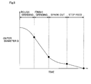
object 1 is larger than the target dimension, when the cutting ability of thegrindstone 4 is worse than a set value, and the amount of elastic deformation of the processedobject 1 is greater than a set value, the amount of elastic restoration of the processedobject 1 becomes large, and the amount of grinding during spark out becomes excessive, so the outer diameter D of the processedobject 1 becomes smaller than the target dimension. Conversely, when the cutting ability of thegrindstone 4 is better than a set value, the amount of elastic restoration of the processedobject 1 during spark out becomes less than a set value, and the amount of grinding of the outer-circumferential surface of the processedobject 1 by spark out becomes less than a set value, so the outer diameter D in the state after grinding of the processedobject 1 is complete becomes larger than the target dimension. When the outer diameter D at the end of spark out of the processedobject 1 is larger than the target dimension, it is feasible to make the outer diameter of the processedobject 1 the target dimension by further performing step-feed grinding of the processedobject 1 as illustrated inFIG. 8 in which the feed speed of thegrindstone 4 and the amount of cutting are very small. However, by adding this process, there is a possibility that the time and work of processing, and the manufacturing cost will increase. - Moreover, when the amount of elastic deformation of the processed
object 1 is less than a set value, and the amount of elastic restoration of the processed object during spark out is small, the time required for releasing the elastic deformation of the processedobject 1 during spark out will be short. However, in the case of conventional construction, the amount of time that spark out is performed is set, based on the set value of the cutting ability of thegrindstone 4, to an amount of time sufficient for sparks and grinding noise from the area of contact between the outer-circumferential surface of the processedobject 1 and the surface of thegrindstone 4 to stop, and for the outer-circumferential surface of the processedobject 1 to become smooth. Therefore, when the cutting ability of thegrindstone 4 is better than a set value, the amount of time that spark out is performed and the overall amount of time that grinding is performed becomes unnecessarily long. - In regard to this,
JP 2000-343425 (A object 1 at the end of spark out, and then adjusting the starting point of spark out in the next grinding after this learning is complete. Moreover,JP 2012-143843 (A -
- [Patent Literature 1]
JP 2000-343425 (A - [Patent Literature 2]
JP 2012-143843 (A - Taking into consideration the problems described above, the object of the present invention is to provide a grinding method that is able to prevent variation in the outer-diameter dimension of a processed object at the completion of spark out, and prevent the amount of time that grinding is performed from becoming unnecessarily long, regardless of change in the amount of elastic deformation of the processed object due to change in the cutting ability of the grindstone and the like.
- The present invention relates to a method for grinding a metal annular member, the method comprising a step of grinding a circumferential surface of a metal annular processed object using a rotating grindstone while measuring a dimension in a radial direction of the processed object in process, the grinding being performed so that after a rough grinding performed at a specified feed speed of the rotating grindstone, a finish grinding is performed by slowing the feed speed of the rotating grindstone, and then a spark out is performed by making the feed speed of the rotating grindstone '0'.
- Particularly, in the method for grinding a metal annular member of the present invention, a condition for at least one of starting the spark out (switching from the finish grinding to the spark out) or ending the spark out is determined based on a rate of change of the dimension in the radial direction of the processed object, which is an amount of change in the dimension in the radial direction per unit time or per one rotation of the processed object.
- More specifically, in the finish grinding, a first threshold value for the rate of change of the dimension in the radial direction of the processed object is determined for each of a plurality of different preset target values for the dimension in the radial direction of the processed object. When the dimension in the radial direction of the processed object becomes one target value of the plurality of different preset target values, the spark out starts (grinding switches from the finish grinding to the spark out) under a condition that an absolute value of the rate of change of the dimension in the radial direction of the processed object becomes greater than the first threshold value that corresponds to the one target value.
- Preferably, the spark out ends when during the spark out an absolute value of the rate of change of the dimension in the radial direction of the processed object becomes less than a second preset threshold value.
- Moreover, the present invention relates to a device for grinding a metal annular member. The device for grinding a metal annular member of the present invention comprises: a means for supporting and fastening a processed object and rotating the processed object; a means for positioning the processed object in a radial direction; a rotating grindstone grinding a circumferential surface of the processed object; a sensor measuring an outer diameter of the processed object; and a controller controlling a rotation of the rotating grindstone based on a measurement result measured by the sensor; the device executing the method for grinding a metal annular member of the present invention.
- In other words, in the device for grinding a metal annular member of the present invention, the controller determines at least one of a timing for starting the spark out or a timing for ending the spark out based on the rate of change of the dimension in the radial direction of the processed object. Preferably, when the dimension in the radial direction of the processed object becomes the one target value of the plurality of different preset target values for the dimension in the radial direction of the processed object, the controller compares the absolute value of the rate of change of the dimension in the radial direction of the processed object with one of first threshold values for the rate of change of the dimension in the radial direction of the processed object that are determined for the plurality of different preset target values for the dimension in the radial direction of the processed object, the one first threshold value corresponding to one of the target values at a particular time, and starts the spark out under a condition that the absolute value of the rate of change of the dimension in the radial direction of the processed object is greater than the one first threshold value corresponding to the one target value at the particular time. Moreover, preferably, the controller ends the spark out when the absolute value of the rate of change of the dimension in the radial direction of the processed object becomes less than a second preset threshold value.
- With the method and device for grinding a metal annular member of the present invention, it is possible to prevent variation in the outer diameter of a processed object at the completion of grinding regardless of change in the amount of elastic deformation of the processed object based on the change in the cutting ability of a grindstone, and prevent the time required for grinding from becoming unnecessarily long. In other words, in the present invention, the condition of at least one of the start of spark out or the end of spark out in the grinding process is set based on the rate of change of the dimension in the radial direction, which is the amount of change of the dimension in the radial direction of the processed object per unit time or per one rotation of the processed object. Therefore, it is possible to perform spark out while taking into consideration the amount of elastic deformation of the processed object.
-
-
FIG. 1A shows a side view illustrating the state of performing grinding of a processed object by an example of a grinding device to which the present invention is applied; andFIG. 1B shows an end view as seen from the right inFIG. 1A of the state illustrated inFIG. 1A . -
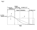
FIG. 2 shows a graph illustrating an example of change in the outer diameter of a processed object during grinding in an example of an embodiment of the present invention. -
FIG. 3 shows a flowchart that illustrates the processing for determining the timing for the start of spark out in this example. -
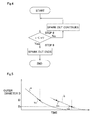
FIG. 4 shows a flowchart that illustrates the processing for determining the timing for the end of spark out in this example. -
FIG. 5 shows a view that corresponds to an enlarged view of section X inFIG. 2 . -
FIG. 6 shows a graph illustrating an example of the feed amount of a grindstone, the outer diameter D of a processed object, and the change in the rate of change v of the outer diameter D during grinding in this example. -
FIG. 7A shows a side view illustrating the state before the grindstone is pressed against a processed object that is supported by a grinding device of conventional technology; andFIG. 7B shows a side view exaggeratedly illustrating the state when the grindstone is pressed against a processed object. -
FIG. 8 shows a graph illustrating an example of the change in the outer diameter of a processed object due to grinding in conventional technology. -
FIG. 1A to FIG. 6 illustrate an example of an embodiment of the present invention. A feature of this example is that, by suitably setting the timing at which spark out begins (change from finish grinding to spark out) and ends in the grinding process, the outer diameter D of a processed object (work) 1 is suppressed from varying in the completed state of processing, and the time required for grinding is prevented from becoming unnecessarily long regardless of change in the amount of elastic deformation of the processedobject 1 due to a change in the cutting ability of thegrindstone 4. The grinding device of this example is basically the same as the construction of a conventional grinding device and comprises: a rotating drive shaft (not illustrated in the figure) that supports and secures a processed object and causes that processed object to rotate; abacking plate 2 that is fastened to the tip end of this rotating drive shaft and magnetically affixes an annular processed object (work) 1 to the end surface thereof; twoshoes 3 that position the processedobject 1 in the radial direction; arotating grindstone 4 that grinds the outer-circumferential surface of the processedobject 1; a sensor (not illustrated in the figure) that comprises at least twogauge heads 5 and measures the outer diameter D of the processedobject 1; and a controller (not illustrated in the figure) that controls the rotation of therotating grindstone 4 based on the measurement results measured by the sensor. As a means for supporting, securing and rotating the processedobject 1, it is possible to use a combination of a rotating drive shaft, and a known chuck device such as a mechanical chuck or magnetic chuck that can be attached to the rotating drive shaft, and that can support and secure the processedobject 1 on the rotating drive shaft. Moreover, as a means for positioning the processedobject 1 in the radial direction, it is also possible to use rollers and the like, or use a combination of an arbitrary number of rollers and shoes. As a sensor for measuring the outer diameter D of the processedobject 1, it is possible to use a contact displacement sensor that uses contacts as the gauge heads 5, or it is possible to use a non-contact sensor that uses laser lights as the gauge heads 5. - The method of grinding in this example, including the method of grinding a processed
object 1 using agrindstone 4, is the same as the basic processing in the conventional method. In other words, in the grinding process of this example, the outer-circumferential surface of the processedobject 1 is grinded using arotating grindstone 4 while measuring the dimension in the radial direction of the processedobject 1 in process, and the grinding process is performed on the outer-circumferential surface of the processedobject 1 in the order: a rough grinding, a finish grinding and a spark out. More specifically, the outer diameter D of the processedobject 1 can be measured in process by twogauge heads 5, and the controller switches from the rough grinding to the finish grinding when the outer diameter D of the processedobject 1 that is measured by the gauge heads 5 reaches a specified value. - A feature of the controller in this example is that the controller determines both the start and end of spark out based on the rate of change v (µm/s), which is the amount of change per unit time of the outer diameter D of the processed
object 1 that is measured by the gauge heads 5. More specifically, in order for the controller to determine the timing of the start of spark out (timing at which grinding is switched from the finish grinding to the spark out), plural (for example, 5 to 6) target values Di are set in advance for the outer diameter D of the processedobject 1. When the number of target values is 5, the value i is a natural number that is no less than 1 and no greater than 5 (1 ≤ i ≤ 5), and the target values Di are set so that D1 > D2 > ... > D5. Furthermore, first threshold values vi are set for the rate of change of the outer diameter D of the processedobject 1 for each of these target values Di. Target values Di and first threshold values vi such as these are found by testing or calculation in advance according to the shape and material of the processedobject 1. In other words, the target values Di and the first threshold values vi change according to the shape and material of the processedobject 1. - The method by which the controller determines the timing for starting spark out based on the rate of change v of the outer diameter D of the processed
object 1 will be explained with reference to the flowchart inFIG. 3 . The work illustrated in this flowchart is executed by the controller from the start of finish grinding to the start of spark out, or until the end of grinding when suitable timing for starting spark out cannot be determined. - First, in
step 1, the controller determines whether or not the outer diameter D of the processedobject 1 that is measured by the gauge heads 5 at that instant is the same as the target value Di (whether or not the outer diameter D is within a specified range with the target value Di being the center value). The initial value of the value i is taken to be 1 (i = 1). When the outer diameter D is not equal to the target value Di (D ≠ Di), processing advances to step 2, and the controller determines whether or not the outer diameter D is less than the target value Di (D < Di). Instep 2, when the outer diameter D is equal to or greater than the target value Di (D ≥ Di) (however, the case instep 1 in which these values are the same (D = Di) is excluded), finish grinding continues, and after a specified amount of time, processing returns to step 1. When the outer diameter D is less than the target value Di (D < Di), processing advances to step 3, and the value i is increased by 1, after which processing advances to step 4. Instep 2 andstep 3, when the outer diameter D is less than the target value Di (D < Di), the outer diameter does not become equal to the target value Di even when finish grinding is continued after that, so this work is a process for making the target value Di that is used for comparison with the outer diameter D a value Di + 1, which is value that is one step smaller. - In
step 4, the controller determines whether or not the value i is equal to or less than the number (total number) n of target values Di. When the value i is greater than the number n of target values Di (i > n), processing advances to step 5, grinding of the processedobject 1 ends and since suitable timing for starting spark out could not be determined, the controller issues a warning from a display such as a buzzer or warning light. When the value i is equal to or less than the number n of target values Di (i ≤ n), then after a specified amount of time has elapsed, processing returns to step 1. In other words,step 4 andstep 5 are performed in the procedure fromstep 1 to step 6 described later, and when suitable timing for staring spark out could not be determined by comparing the outer diameter D of the processedobject 1 with the minimum target value Dn of the target values Di, this procedure becomes a procedure for ending grinding in error (exception process). - On the other hand, in
step 1, when the outer diameter D is the same as the target value Di (D = Di), processing advances to step 6, and the controller determines whether or not the absolute value of the rate of change v of the outer diameter D of the processedobject 1 at that instant is greater than the first threshold value vi that corresponds to the target value Di. When the absolute value of the rate of change v is greater than the first threshold value vi (|v| > vi), processing advances to step 7, the controller starts spark out (the feed speed of thegrindstone 4 is made "0") and ends the procedure for determined the timing for starting spark out. When the absolute value of the rate of change v is equal to or less than the first threshold value vi (|v| ≤ vi), processing advances to the procedure fromstep 3 to step 4, after which the controller performs processing according to the procedure described above. - After spark out has started, the controller determines the timing for ending spark out according to the procedure illustrated in
FIG. 4 . The work illustrated in the flowchart inFIG. 4 is executed by the controller from after the start of spark out until spark out ends. First, instep 8, the controller determines whether or not the absolute value of the rate of change v is less than a second preset threshold value vf that was set in advance at specified periods of time (fixed time). Then, when the absolute value of the rate of change v becomes less than the second threshold value vf (|v| < vf), processing advances to step 9, and the controller ends spark out. On the other hand, when the absolute value of the rate of change v is equal to or greater than the second threshold value vf (|v| ≥ vf), spark out continues without ending, and after a specified amount of time elapses, processing returns to step 8. The second threshold value vf is found by experimentation or calculation in advance. When it is particularly necessary to keep the tolerances of dimensions small (for example, 1 µm or less), then after spark out has ended, it is also possible to perform step-feed grinding of the processedobject 1 in which the feed speed of thegrindstone 4 and the cutting amount ofgrindstone 4 are very small in order to make the outer diameter D of the processed object equal to the target dimension. - With the method for grinding a metal annular member of the present invention, even when variation occurs in the amount of elastic deformation of the processed
object 1 based on the change in the cutting ability of thegrindstone 4, it is possible to prevent the outer diameter of the processedobject 1 at the end of spark out from varying, and it is possible to prevent the time required for grinding from become unnecessarily long. In other words, in this example, in order to determine the timing for starting and ending spark out, the rate of change v, which is the amount of change per unit time of the outer diameter D of the processedobject 1, is used. That is, the timing for starting and ending spark out can be determined by taking into consideration the amount of elastic deformation of the processed object. Here, the reason that the timing for starting spark out can be determined while taking into consideration the elastic deformation of the processedobject 1 will be explained with reference toFIG. 2 andFIG. 5 .FIG. 2 andFIG. 5 illustrate the change in the outer diameter D of the processedobject 1 that is measured in process bygauge heads 5 when the amount of elastic deformation of the processedobject 1 due to pressing by thegrindstone 4 became large due to degradation of the cutting ability of the grindstone 4 (solid line a), and when the amount of elastic deformation of the processedobject 1 is small before degradation of the cutting ability of the grindstone 4 (dashed line b). - In
FIG. 2 , in order to clarify that the time required for performing spark out from finish grinding changes according to the differences in the amount of elastic deformation of the processedobject 1, switching from rough grinding to finish grinding is illustrated such that the timing is the same for when the amount of elastic deformation of the processedobject 1 is large and small. Actually, switching from rough grinding to finish grinding is performed when the outer diameter D of the processedobject 1 becomes a specified value, so the timing of this switching changes according to the change in the cutting ability of thegrindstone 4. The larger the amount of elastic deformation of the processedobject 1 is during rough grinding as the cutting ability degrades, the larger the amount that the processedobject 1 is elastically restored during spark out becomes, and the amount of grinding in spark out increases. Therefore, the larger the elastic deformation of the processedobject 1 is, in order to decreasing the amount of grinding by finish grinding, it is necessary to end finish grinding earlier and switching from finish grinding to spark out earlier (spark out is started when the outer diameter D of the processedobject 1 is large). - As can be clearly seen from
FIG. 2 andFIG. 5 , during finish grinding, when the outer diameter D is the same (for example D = Di), the amount of elastic deformation of the processedobject 1 in rough grinding is large, and the rate of change va1 when the amount that the processedobject 1 is elastically restored is large is greater than the rate of change vb1 when the amount that the processedobject 1 is elastically restored is small (va1 > vb1). Therefore, the first threshold value v1 that corresponds to the target value D1 is regulated so as to be less than the rate of change va1 when the amount of elastic deformation of the processedobject 1 is large, and so as to be equal to or greater than the rate of change vb1 when the amount of elastic deformation of the processedobject 1 is small (vb1 ≤ v1 < va1). Moreover, the first threshold value v2 that corresponds to the target value D2 that is smaller than the target value D1 is regulated so as to be less than the rate of change vb2 at the time when the outer diameter D of the processedobject 1 is the same as the target value D2 (v2 < vb2) in case that the amount of elastic deformation of the processedobject 1 is small. By regulating the target values Di and the first threshold values vi in this way, the condition (va1 > v1) for starting spark out instep 6 is satisfied when the outer diameter D of the processedobject 1 becomes the same as the target value D1 (D = D1) by finish grinding, so spark out starts. - On the other hand, when the amount of elastic deformation of the processed
object 1 is small, the condition (vb1 ≤ v1) instep 6 is not satisfied (in the case of switching to spark out as is, the outer diameter of the processedobject 1 would be larger than the target dimension), so spark out cannot be started and finish grinding continues. As finish grinding is further performed, the outer diameter D becomes small, and when the outer diameter D becomes the same as the target value D2 (D = D2), the condition (vb2 ≤ v2) instep 6 is satisfied, so spark out starts. In this way, plural target values Di are set for the outer diameter D, and by setting first threshold values vi for each of the target values Di so that the smaller the values of the target values Di become, the first threshold values vi that correspond to the target values Di become small, and it is possible to determine the timing for starting spark out (switching from finish grinding to spark out) while taking into consideration the amount of elastic deformation of the processedobject 1. - On the other hand, in determining the end of spark out in this example, spark out ends when the rate of change v becomes less than the second threshold value vf (practically becomes 0 except in the case of measurement error) regardless of the change in the size of the amount of elastic deformation due to degradation of the cutting ability of the
grindstone 4. The rate of change v practically becomes 0 when the elastic deformation of the processedobject 1 is released, and the outer-circumferential surface of the processed object becomes smooth. Therefore, when the cutting ability of thegrindstone 4 is good and the amount of elastic deformation is small, the time that is required for elastic deformation of the processed object to be released is short, so it is possible to end spark out earlier. However, when the cutting ability of thegrindstone 4 is bad, and the amount of elastic deformation is large, the time required for releasing the elastic deformation of the processedobject 1 becomes long, and the time for performing spark out can be sufficiently maintained. In this way, in this example, it is possible to determine suitable timing for ending spark out regardless of change in the size of elastic deformation. Therefore, in this example, it is possible to prevent variation in the outer diameter of the processedobject 1 at the completion of grinding regardless of change in the amount of elastic deformation of theprocess object 1 due to change in the cutting ability of thegrindstone 4, and it is possible to prevent the time required for grinding from becoming unnecessarily long. - The method and device for grinding a metal annular member of the present invention can be applied not only in the case of performing grinding of the outer-circumferential surface of a metal annular processed object, but can also be applied in the case of grinding the inner-circumferential surface.
-
- 1
- Processed object
- 2
- Backing plate
- 3
- Shoe
- 4
- Grindstone
- 5
- Measurement gauge
Claims (6)
- A method for grinding a metal annular member, comprising a step of grinding a circumferential surface of a metal annular processed object using a rotating grindstone while measuring a dimension in a radial direction of the processed object in process,
the grinding comprising a rough grinding, a finish grinding, and a spark out in order,
wherein a condition for at least one of starting the spark out or ending the spark out is determined based on a rate of change of the dimension in the radial direction of the processed object. - The method for grinding a metal annular member according to Claim 1, wherein a first threshold value for the rate of change of the dimension in the radial direction of the processed object is determined for each of a plurality of different preset target values for the dimension in the radial direction of the processed object, and when the dimension in the radial direction of the processed object becomes one target value of the plurality of different preset target values, the spark out starts under a condition that an absolute value of the rate of change of the dimension in the radial direction of the processed object becomes greater than the first threshold value that corresponds to the one target value.
- The method for grinding a metal annular member according to Claim 1, wherein the spark out ends when an absolute value of the rate of change of the dimension in the radial direction of the processed object becomes less than a second preset threshold value.
- A device for grinding a metal annular member, comprising:a means for supporting and fastening a metal annular processed object and rotating the processed object;a means for positioning the processed object in a radial direction;a rotating grindstone grinding a circumferential surface of the processed object;a sensor measuring an outer diameter of the processed object; anda controller controlling a rotation of the rotating grindstone based on a measurement result measured by the sensor; whereinwhen using the rotating grindstone to perform grinding of the circumferential surface of the processed object, the grinding comprising a rough grinding, a finish grinding and a spark out in order, while measuring a dimension in the radial direction of the processed object, the controller determines at least one of a timing for starting the spark out or a timing for ending the spark out based on a rate of change of the dimension in the radial direction of the processed object.
- The device for grinding a metal annular member according to Claim 4, wherein, when the dimension in the radial direction of the processed object becomes one target value of a plurality of different preset target values for the dimension in the radial direction of the processed object, the controller compares an absolute value of the rate of change of the dimension in the radial direction of the processed object with one of first threshold values for the rate of change of the dimension in the radial direction of the processed object that are determined for each of the plurality of different preset target values for the dimension in the radial direction of the processed object, the one first threshold value corresponding to one of the target values at a particular time, and starts the spark out under a condition that the absolute value of the rate of change of the dimension in the radial direction of the processed object is greater than the one first threshold value corresponding to the one target value at the particular time.
- The device for grinding a metal annular member according to Claim 4, wherein the controller ends the spark out when the absolute value of the rate of change of the dimension in the radial direction of the processed object becomes less than a second preset threshold value.
Applications Claiming Priority (2)
| Application Number | Priority Date | Filing Date | Title |
|---|---|---|---|
| JP2012280550 | 2012-12-25 | ||
| PCT/JP2013/083786 WO2014103806A1 (en) | 2012-12-25 | 2013-12-17 | Method and device for grinding metal annular member |
Publications (3)
| Publication Number | Publication Date |
|---|---|
| EP2942153A1 true EP2942153A1 (en) | 2015-11-11 |
| EP2942153A4 EP2942153A4 (en) | 2017-03-01 |
| EP2942153B1 EP2942153B1 (en) | 2019-10-23 |
Family
ID=51020893
Family Applications (1)
| Application Number | Title | Priority Date | Filing Date |
|---|---|---|---|
| EP13869417.9A Active EP2942153B1 (en) | 2012-12-25 | 2013-12-17 | Method and device for grinding metal annular member |
Country Status (5)
| Country | Link |
|---|---|
| US (1) | US9914194B2 (en) |
| EP (1) | EP2942153B1 (en) |
| JP (1) | JP5692420B2 (en) |
| CN (1) | CN104010768B (en) |
| WO (1) | WO2014103806A1 (en) |
Families Citing this family (5)
| Publication number | Priority date | Publication date | Assignee | Title |
|---|---|---|---|---|
| CN103874563B (en) * | 2011-10-19 | 2017-04-12 | 沃尔特机器制造有限责任公司 | Method and device for machining a rotary tool with a plurality of cutting bodies |
| CN104827398B (en) * | 2015-04-09 | 2017-06-13 | 北京第二机床厂有限公司 | Follow in being ground and follow diameter measuring method and device online |
| DE102015206565B4 (en) | 2015-04-13 | 2024-02-08 | Erwin Junker Grinding Technology A.S. | METHOD AND SYSTEM FOR EXTERNAL GRINDING OF SHAFT PARTS BETWEEN CENTERS |
| JP6488894B2 (en) * | 2015-06-05 | 2019-03-27 | 株式会社ジェイテクト | Cylindrical workpiece grinding machine |
| JP6578772B2 (en) * | 2015-07-07 | 2019-09-25 | 株式会社ジェイテクト | Cylindrical grinding method and cylindrical grinding machine |
Family Cites Families (20)
| Publication number | Priority date | Publication date | Assignee | Title |
|---|---|---|---|---|
| US3703054A (en) | 1971-05-17 | 1972-11-21 | Cincinnati Milacron Heald | Grinding machine |
| JPS54125590A (en) | 1978-03-22 | 1979-09-29 | Ntn Toyo Bearing Co Ltd | Grinding control method in complex grinding |
| JPH01171743A (en) | 1987-12-28 | 1989-07-06 | Mitsubishi Heavy Ind Ltd | Grinding method |
| US4926337A (en) * | 1988-07-13 | 1990-05-15 | Bryant Grinder Corporation | Automatic workpart centering mechanism for a chuck |
| US5562526A (en) | 1993-03-29 | 1996-10-08 | Toyoda Koki Kabushiki Kaisha | Method and apparatus for grinding a workpiece |
| JP3528197B2 (en) | 1993-03-29 | 2004-05-17 | 豊田工機株式会社 | Grinding equipment |
| JP3413938B2 (en) | 1993-03-29 | 2003-06-09 | 豊田工機株式会社 | Grinding equipment |
| JP3467807B2 (en) * | 1993-09-30 | 2003-11-17 | 豊田工機株式会社 | Grinding equipment |
| JPH09314439A (en) * | 1996-05-28 | 1997-12-09 | Denso Corp | Grinding method |
| JP2000158292A (en) | 1998-11-20 | 2000-06-13 | Nsk Ltd | Machine part processing method |
| DE19857364A1 (en) * | 1998-12-11 | 2000-06-29 | Junker Erwin Maschf Gmbh | Process and grinding machine for process control when peeling a workpiece |
| JP2000343425A (en) | 1999-06-08 | 2000-12-12 | Mitsubishi Heavy Ind Ltd | Grinding machine |
| JP3787248B2 (en) * | 1999-09-30 | 2006-06-21 | 株式会社ジェイテクト | Method and apparatus for controlling sizing of machine tool |
| JP2001269864A (en) | 2000-03-24 | 2001-10-02 | Toyoda Mach Works Ltd | Machine tool provided with radius measurement sizing device |
| JP2003094335A (en) | 2001-09-26 | 2003-04-03 | Toyoda Mach Works Ltd | Grinding fluid feed method and device in grinder |
| JP2005059141A (en) | 2003-08-12 | 2005-03-10 | Kazuhito Ohashi | Grinding method and controller of grinder |
| JP4923549B2 (en) * | 2005-12-08 | 2012-04-25 | 株式会社ジェイテクト | Mounting structure for sizing equipment |
| DE102007026562B4 (en) * | 2007-06-08 | 2010-08-26 | Erwin Junker Maschinenfabrik Gmbh | Grinding center and method for simultaneously grinding multiple bearings of crankshafts |
| JP5332507B2 (en) | 2008-10-28 | 2013-11-06 | 株式会社ジェイテクト | Grinding machine and grinding method |
| JP5611061B2 (en) | 2011-01-13 | 2014-10-22 | トーヨーエイテック株式会社 | Internal grinding machine |
-
2013
- 2013-12-17 JP JP2013557303A patent/JP5692420B2/en active Active
- 2013-12-17 CN CN201380002625.5A patent/CN104010768B/en active Active
- 2013-12-17 WO PCT/JP2013/083786 patent/WO2014103806A1/en not_active Ceased
- 2013-12-17 EP EP13869417.9A patent/EP2942153B1/en active Active
- 2013-12-17 US US14/758,130 patent/US9914194B2/en active Active
Non-Patent Citations (1)
| Title |
|---|
| See references of WO2014103806A1 * |
Also Published As
| Publication number | Publication date |
|---|---|
| US9914194B2 (en) | 2018-03-13 |
| JP5692420B2 (en) | 2015-04-01 |
| WO2014103806A1 (en) | 2014-07-03 |
| CN104010768A (en) | 2014-08-27 |
| JPWO2014103806A1 (en) | 2017-01-12 |
| CN104010768B (en) | 2016-09-07 |
| EP2942153A4 (en) | 2017-03-01 |
| US20150343598A1 (en) | 2015-12-03 |
| EP2942153B1 (en) | 2019-10-23 |
Similar Documents
| Publication | Publication Date | Title |
|---|---|---|
| EP2942153B1 (en) | Method and device for grinding metal annular member | |
| US9446499B2 (en) | Grinding wheel truing method and grinding machine | |
| US20130326880A1 (en) | Method of manufacturing bearing ring of rolling bearing | |
| US9238289B2 (en) | Grinding method of grinding roller workpiece and grinding apparatus for grinding roller workpiece | |
| TW201436949A (en) | Grinding processing method | |
| JP2010240807A (en) | Workpiece supply device for machining roller end face, roller end face working machine, and roller for rolling bearing | |
| EP3804894B1 (en) | Circular band saw blade manufacturing method and manufacturing method and apparatus | |
| EP2596909A2 (en) | Actual grinding depth measurement method, machining method, and machine tool | |
| US20160074928A1 (en) | Hub unit manufacturing apparatus | |
| US10486288B2 (en) | Cylindrical grinding method and cylindrical grinding machine | |
| JP5592294B2 (en) | Grinding method of work inner surface | |
| KR100189392B1 (en) | Method and apparatus for slicing a work | |
| RU2415004C1 (en) | Method of centreless ball grinding | |
| US20160252432A1 (en) | Pressing load setting method of tire testing machine | |
| JP3835255B2 (en) | Gear tooth surface processing method and apparatus | |
| RU2401189C2 (en) | Device for simultaneous grinding of chamfers on roller bearing rollers | |
| US8444453B2 (en) | Device and method for fine or finest processing of a rotationally symmetric work piece surface | |
| JP5367246B2 (en) | Semiconductor wafer polishing apparatus and polishing method | |
| US20200262021A1 (en) | Manufacturing apparatus for producing a curved contour on at least one end face of a roll and method for producing a curved contour on the at least one end face with the manufacturing apparatus | |
| US10287890B2 (en) | Abrasive processing method | |
| JP2005205509A (en) | Grinding processing method of outer peripheral surface of annular article | |
| JP4150897B2 (en) | Super finishing device for ball bearing raceway and super finishing method | |
| JP3944640B2 (en) | Single-side grinding method and apparatus | |
| JP2006116634A (en) | Surface grinding method and grinding apparatus for sheet metal ring | |
| JP2004092726A (en) | Method of manufacturing bearing race and bearing |
Legal Events
| Date | Code | Title | Description |
|---|---|---|---|
| PUAI | Public reference made under article 153(3) epc to a published international application that has entered the european phase |
Free format text: ORIGINAL CODE: 0009012 |
|
| 17P | Request for examination filed |
Effective date: 20150722 |
|
| AK | Designated contracting states |
Kind code of ref document: A1 Designated state(s): AL AT BE BG CH CY CZ DE DK EE ES FI FR GB GR HR HU IE IS IT LI LT LU LV MC MK MT NL NO PL PT RO RS SE SI SK SM TR |
|
| AX | Request for extension of the european patent |
Extension state: BA ME |
|
| DAX | Request for extension of the european patent (deleted) | ||
| A4 | Supplementary search report drawn up and despatched |
Effective date: 20170131 |
|
| RIC1 | Information provided on ipc code assigned before grant |
Ipc: B24B 49/04 20060101AFI20170120BHEP Ipc: B24B 5/04 20060101ALI20170120BHEP Ipc: B24B 5/35 20060101ALI20170120BHEP Ipc: G05B 19/18 20060101ALI20170120BHEP |
|
| GRAP | Despatch of communication of intention to grant a patent |
Free format text: ORIGINAL CODE: EPIDOSNIGR1 |
|
| STAA | Information on the status of an ep patent application or granted ep patent |
Free format text: STATUS: GRANT OF PATENT IS INTENDED |
|
| INTG | Intention to grant announced |
Effective date: 20190508 |
|
| GRAS | Grant fee paid |
Free format text: ORIGINAL CODE: EPIDOSNIGR3 |
|
| GRAA | (expected) grant |
Free format text: ORIGINAL CODE: 0009210 |
|
| STAA | Information on the status of an ep patent application or granted ep patent |
Free format text: STATUS: THE PATENT HAS BEEN GRANTED |
|
| AK | Designated contracting states |
Kind code of ref document: B1 Designated state(s): AL AT BE BG CH CY CZ DE DK EE ES FI FR GB GR HR HU IE IS IT LI LT LU LV MC MK MT NL NO PL PT RO RS SE SI SK SM TR |
|
| REG | Reference to a national code |
Ref country code: GB Ref legal event code: FG4D |
|
| REG | Reference to a national code |
Ref country code: CH Ref legal event code: EP |
|
| REG | Reference to a national code |
Ref country code: IE Ref legal event code: FG4D |
|
| REG | Reference to a national code |
Ref country code: DE Ref legal event code: R096 Ref document number: 602013062123 Country of ref document: DE |
|
| REG | Reference to a national code |
Ref country code: AT Ref legal event code: REF Ref document number: 1193145 Country of ref document: AT Kind code of ref document: T Effective date: 20191115 |
|
| REG | Reference to a national code |
Ref country code: NL Ref legal event code: MP Effective date: 20191023 |
|
| PGFP | Annual fee paid to national office [announced via postgrant information from national office to epo] |
Ref country code: FR Payment date: 20191128 Year of fee payment: 7 |
|
| REG | Reference to a national code |
Ref country code: LT Ref legal event code: MG4D |
|
| PG25 | Lapsed in a contracting state [announced via postgrant information from national office to epo] |
Ref country code: BG Free format text: LAPSE BECAUSE OF FAILURE TO SUBMIT A TRANSLATION OF THE DESCRIPTION OR TO PAY THE FEE WITHIN THE PRESCRIBED TIME-LIMIT Effective date: 20200123 Ref country code: FI Free format text: LAPSE BECAUSE OF FAILURE TO SUBMIT A TRANSLATION OF THE DESCRIPTION OR TO PAY THE FEE WITHIN THE PRESCRIBED TIME-LIMIT Effective date: 20191023 Ref country code: PT Free format text: LAPSE BECAUSE OF FAILURE TO SUBMIT A TRANSLATION OF THE DESCRIPTION OR TO PAY THE FEE WITHIN THE PRESCRIBED TIME-LIMIT Effective date: 20200224 Ref country code: GR Free format text: LAPSE BECAUSE OF FAILURE TO SUBMIT A TRANSLATION OF THE DESCRIPTION OR TO PAY THE FEE WITHIN THE PRESCRIBED TIME-LIMIT Effective date: 20200124 Ref country code: PL Free format text: LAPSE BECAUSE OF FAILURE TO SUBMIT A TRANSLATION OF THE DESCRIPTION OR TO PAY THE FEE WITHIN THE PRESCRIBED TIME-LIMIT Effective date: 20191023 Ref country code: NO Free format text: LAPSE BECAUSE OF FAILURE TO SUBMIT A TRANSLATION OF THE DESCRIPTION OR TO PAY THE FEE WITHIN THE PRESCRIBED TIME-LIMIT Effective date: 20200123 Ref country code: LV Free format text: LAPSE BECAUSE OF FAILURE TO SUBMIT A TRANSLATION OF THE DESCRIPTION OR TO PAY THE FEE WITHIN THE PRESCRIBED TIME-LIMIT Effective date: 20191023 Ref country code: SE Free format text: LAPSE BECAUSE OF FAILURE TO SUBMIT A TRANSLATION OF THE DESCRIPTION OR TO PAY THE FEE WITHIN THE PRESCRIBED TIME-LIMIT Effective date: 20191023 Ref country code: NL Free format text: LAPSE BECAUSE OF FAILURE TO SUBMIT A TRANSLATION OF THE DESCRIPTION OR TO PAY THE FEE WITHIN THE PRESCRIBED TIME-LIMIT Effective date: 20191023 Ref country code: LT Free format text: LAPSE BECAUSE OF FAILURE TO SUBMIT A TRANSLATION OF THE DESCRIPTION OR TO PAY THE FEE WITHIN THE PRESCRIBED TIME-LIMIT Effective date: 20191023 Ref country code: ES Free format text: LAPSE BECAUSE OF FAILURE TO SUBMIT A TRANSLATION OF THE DESCRIPTION OR TO PAY THE FEE WITHIN THE PRESCRIBED TIME-LIMIT Effective date: 20191023 |
|
| PGFP | Annual fee paid to national office [announced via postgrant information from national office to epo] |
Ref country code: GB Payment date: 20191213 Year of fee payment: 7 |
|
| PG25 | Lapsed in a contracting state [announced via postgrant information from national office to epo] |
Ref country code: RS Free format text: LAPSE BECAUSE OF FAILURE TO SUBMIT A TRANSLATION OF THE DESCRIPTION OR TO PAY THE FEE WITHIN THE PRESCRIBED TIME-LIMIT Effective date: 20191023 Ref country code: HR Free format text: LAPSE BECAUSE OF FAILURE TO SUBMIT A TRANSLATION OF THE DESCRIPTION OR TO PAY THE FEE WITHIN THE PRESCRIBED TIME-LIMIT Effective date: 20191023 Ref country code: IS Free format text: LAPSE BECAUSE OF FAILURE TO SUBMIT A TRANSLATION OF THE DESCRIPTION OR TO PAY THE FEE WITHIN THE PRESCRIBED TIME-LIMIT Effective date: 20200224 |
|
| PG25 | Lapsed in a contracting state [announced via postgrant information from national office to epo] |
Ref country code: AL Free format text: LAPSE BECAUSE OF FAILURE TO SUBMIT A TRANSLATION OF THE DESCRIPTION OR TO PAY THE FEE WITHIN THE PRESCRIBED TIME-LIMIT Effective date: 20191023 |
|
| REG | Reference to a national code |
Ref country code: DE Ref legal event code: R097 Ref document number: 602013062123 Country of ref document: DE |
|
| PG2D | Information on lapse in contracting state deleted |
Ref country code: IS |
|
| PG25 | Lapsed in a contracting state [announced via postgrant information from national office to epo] |
Ref country code: DK Free format text: LAPSE BECAUSE OF FAILURE TO SUBMIT A TRANSLATION OF THE DESCRIPTION OR TO PAY THE FEE WITHIN THE PRESCRIBED TIME-LIMIT Effective date: 20191023 Ref country code: EE Free format text: LAPSE BECAUSE OF FAILURE TO SUBMIT A TRANSLATION OF THE DESCRIPTION OR TO PAY THE FEE WITHIN THE PRESCRIBED TIME-LIMIT Effective date: 20191023 Ref country code: CZ Free format text: LAPSE BECAUSE OF FAILURE TO SUBMIT A TRANSLATION OF THE DESCRIPTION OR TO PAY THE FEE WITHIN THE PRESCRIBED TIME-LIMIT Effective date: 20191023 Ref country code: RO Free format text: LAPSE BECAUSE OF FAILURE TO SUBMIT A TRANSLATION OF THE DESCRIPTION OR TO PAY THE FEE WITHIN THE PRESCRIBED TIME-LIMIT Effective date: 20191023 Ref country code: IS Free format text: LAPSE BECAUSE OF FAILURE TO SUBMIT A TRANSLATION OF THE DESCRIPTION OR TO PAY THE FEE WITHIN THE PRESCRIBED TIME-LIMIT Effective date: 20200223 |
|
| REG | Reference to a national code |
Ref country code: CH Ref legal event code: PL |
|
| REG | Reference to a national code |
Ref country code: AT Ref legal event code: MK05 Ref document number: 1193145 Country of ref document: AT Kind code of ref document: T Effective date: 20191023 |
|
| REG | Reference to a national code |
Ref country code: BE Ref legal event code: MM Effective date: 20191231 |
|
| PLBE | No opposition filed within time limit |
Free format text: ORIGINAL CODE: 0009261 |
|
| STAA | Information on the status of an ep patent application or granted ep patent |
Free format text: STATUS: NO OPPOSITION FILED WITHIN TIME LIMIT |
|
| PG25 | Lapsed in a contracting state [announced via postgrant information from national office to epo] |
Ref country code: MC Free format text: LAPSE BECAUSE OF FAILURE TO SUBMIT A TRANSLATION OF THE DESCRIPTION OR TO PAY THE FEE WITHIN THE PRESCRIBED TIME-LIMIT Effective date: 20191023 Ref country code: SM Free format text: LAPSE BECAUSE OF FAILURE TO SUBMIT A TRANSLATION OF THE DESCRIPTION OR TO PAY THE FEE WITHIN THE PRESCRIBED TIME-LIMIT Effective date: 20191023 Ref country code: IT Free format text: LAPSE BECAUSE OF FAILURE TO SUBMIT A TRANSLATION OF THE DESCRIPTION OR TO PAY THE FEE WITHIN THE PRESCRIBED TIME-LIMIT Effective date: 20191023 Ref country code: SK Free format text: LAPSE BECAUSE OF FAILURE TO SUBMIT A TRANSLATION OF THE DESCRIPTION OR TO PAY THE FEE WITHIN THE PRESCRIBED TIME-LIMIT Effective date: 20191023 |
|
| 26N | No opposition filed |
Effective date: 20200724 |
|
| PG25 | Lapsed in a contracting state [announced via postgrant information from national office to epo] |
Ref country code: LU Free format text: LAPSE BECAUSE OF NON-PAYMENT OF DUE FEES Effective date: 20191217 Ref country code: IE Free format text: LAPSE BECAUSE OF NON-PAYMENT OF DUE FEES Effective date: 20191217 |
|
| PG25 | Lapsed in a contracting state [announced via postgrant information from national office to epo] |
Ref country code: LI Free format text: LAPSE BECAUSE OF NON-PAYMENT OF DUE FEES Effective date: 20191231 Ref country code: AT Free format text: LAPSE BECAUSE OF FAILURE TO SUBMIT A TRANSLATION OF THE DESCRIPTION OR TO PAY THE FEE WITHIN THE PRESCRIBED TIME-LIMIT Effective date: 20191023 Ref country code: BE Free format text: LAPSE BECAUSE OF NON-PAYMENT OF DUE FEES Effective date: 20191231 Ref country code: CH Free format text: LAPSE BECAUSE OF NON-PAYMENT OF DUE FEES Effective date: 20191231 Ref country code: SI Free format text: LAPSE BECAUSE OF FAILURE TO SUBMIT A TRANSLATION OF THE DESCRIPTION OR TO PAY THE FEE WITHIN THE PRESCRIBED TIME-LIMIT Effective date: 20191023 |
|
| PG25 | Lapsed in a contracting state [announced via postgrant information from national office to epo] |
Ref country code: CY Free format text: LAPSE BECAUSE OF FAILURE TO SUBMIT A TRANSLATION OF THE DESCRIPTION OR TO PAY THE FEE WITHIN THE PRESCRIBED TIME-LIMIT Effective date: 20191023 |
|
| PG25 | Lapsed in a contracting state [announced via postgrant information from national office to epo] |
Ref country code: MT Free format text: LAPSE BECAUSE OF FAILURE TO SUBMIT A TRANSLATION OF THE DESCRIPTION OR TO PAY THE FEE WITHIN THE PRESCRIBED TIME-LIMIT Effective date: 20191023 Ref country code: HU Free format text: LAPSE BECAUSE OF FAILURE TO SUBMIT A TRANSLATION OF THE DESCRIPTION OR TO PAY THE FEE WITHIN THE PRESCRIBED TIME-LIMIT; INVALID AB INITIO Effective date: 20131217 |
|
| GBPC | Gb: european patent ceased through non-payment of renewal fee |
Effective date: 20201217 |
|
| PG25 | Lapsed in a contracting state [announced via postgrant information from national office to epo] |
Ref country code: FR Free format text: LAPSE BECAUSE OF NON-PAYMENT OF DUE FEES Effective date: 20201231 |
|
| PG25 | Lapsed in a contracting state [announced via postgrant information from national office to epo] |
Ref country code: GB Free format text: LAPSE BECAUSE OF NON-PAYMENT OF DUE FEES Effective date: 20201217 |
|
| PG25 | Lapsed in a contracting state [announced via postgrant information from national office to epo] |
Ref country code: TR Free format text: LAPSE BECAUSE OF FAILURE TO SUBMIT A TRANSLATION OF THE DESCRIPTION OR TO PAY THE FEE WITHIN THE PRESCRIBED TIME-LIMIT Effective date: 20191023 |
|
| PG25 | Lapsed in a contracting state [announced via postgrant information from national office to epo] |
Ref country code: MK Free format text: LAPSE BECAUSE OF FAILURE TO SUBMIT A TRANSLATION OF THE DESCRIPTION OR TO PAY THE FEE WITHIN THE PRESCRIBED TIME-LIMIT Effective date: 20191023 |
|
| PGFP | Annual fee paid to national office [announced via postgrant information from national office to epo] |
Ref country code: DE Payment date: 20251028 Year of fee payment: 13 |