EP2942034B1 - Implantation system for inserting a vein filter - Google Patents
Implantation system for inserting a vein filter Download PDFInfo
- Publication number
- EP2942034B1 EP2942034B1 EP15166102.2A EP15166102A EP2942034B1 EP 2942034 B1 EP2942034 B1 EP 2942034B1 EP 15166102 A EP15166102 A EP 15166102A EP 2942034 B1 EP2942034 B1 EP 2942034B1
- Authority
- EP
- European Patent Office
- Prior art keywords
- pusher
- sheath
- filter
- centering structure
- centering
- Prior art date
- Legal status (The legal status is an assumption and is not a legal conclusion. Google has not performed a legal analysis and makes no representation as to the accuracy of the status listed.)
- Active
Links
- 238000002513 implantation Methods 0.000 title claims description 6
- 210000003462 vein Anatomy 0.000 title description 6
- 239000007943 implant Substances 0.000 claims description 12
- 230000002792 vascular Effects 0.000 claims description 9
- 239000012781 shape memory material Substances 0.000 claims description 5
- 230000007246 mechanism Effects 0.000 description 16
- 238000000034 method Methods 0.000 description 14
- 239000000463 material Substances 0.000 description 6
- 238000004873 anchoring Methods 0.000 description 4
- 229910001220 stainless steel Inorganic materials 0.000 description 4
- 239000010935 stainless steel Substances 0.000 description 4
- 210000001631 vena cava inferior Anatomy 0.000 description 4
- 208000007536 Thrombosis Diseases 0.000 description 3
- 238000013459 approach Methods 0.000 description 3
- 238000002788 crimping Methods 0.000 description 3
- 239000003814 drug Substances 0.000 description 3
- 229940079593 drug Drugs 0.000 description 3
- 238000001914 filtration Methods 0.000 description 3
- 210000004072 lung Anatomy 0.000 description 3
- 238000005476 soldering Methods 0.000 description 3
- 238000001356 surgical procedure Methods 0.000 description 3
- 238000003466 welding Methods 0.000 description 3
- 229920002614 Polyether block amide Polymers 0.000 description 2
- 208000010378 Pulmonary Embolism Diseases 0.000 description 2
- 210000003484 anatomy Anatomy 0.000 description 2
- 230000004888 barrier function Effects 0.000 description 2
- 239000008280 blood Substances 0.000 description 2
- 210000004369 blood Anatomy 0.000 description 2
- 230000017531 blood circulation Effects 0.000 description 2
- 238000013461 design Methods 0.000 description 2
- 210000003191 femoral vein Anatomy 0.000 description 2
- 238000003780 insertion Methods 0.000 description 2
- 230000037431 insertion Effects 0.000 description 2
- 238000005304 joining Methods 0.000 description 2
- 239000000203 mixture Substances 0.000 description 2
- 238000012986 modification Methods 0.000 description 2
- 230000004048 modification Effects 0.000 description 2
- HLXZNVUGXRDIFK-UHFFFAOYSA-N nickel titanium Chemical compound [Ti].[Ti].[Ti].[Ti].[Ti].[Ti].[Ti].[Ti].[Ti].[Ti].[Ti].[Ni].[Ni].[Ni].[Ni].[Ni].[Ni].[Ni].[Ni].[Ni].[Ni].[Ni].[Ni].[Ni].[Ni] HLXZNVUGXRDIFK-UHFFFAOYSA-N 0.000 description 2
- 229910001000 nickel titanium Inorganic materials 0.000 description 2
- HTTJABKRGRZYRN-UHFFFAOYSA-N Heparin Chemical compound OC1C(NC(=O)C)C(O)OC(COS(O)(=O)=O)C1OC1C(OS(O)(=O)=O)C(O)C(OC2C(C(OS(O)(=O)=O)C(OC3C(C(O)C(O)C(O3)C(O)=O)OS(O)(=O)=O)C(CO)O2)NS(O)(=O)=O)C(C(O)=O)O1 HTTJABKRGRZYRN-UHFFFAOYSA-N 0.000 description 1
- FAPWRFPIFSIZLT-UHFFFAOYSA-M Sodium chloride Chemical compound [Na+].[Cl-] FAPWRFPIFSIZLT-UHFFFAOYSA-M 0.000 description 1
- 239000003146 anticoagulant agent Substances 0.000 description 1
- 229940127219 anticoagulant drug Drugs 0.000 description 1
- 230000000740 bleeding effect Effects 0.000 description 1
- 239000011248 coating agent Substances 0.000 description 1
- 238000000576 coating method Methods 0.000 description 1
- 230000003247 decreasing effect Effects 0.000 description 1
- 238000002716 delivery method Methods 0.000 description 1
- 230000001419 dependent effect Effects 0.000 description 1
- 229910003460 diamond Inorganic materials 0.000 description 1
- 239000010432 diamond Substances 0.000 description 1
- 239000012530 fluid Substances 0.000 description 1
- 210000003709 heart valve Anatomy 0.000 description 1
- 229960002897 heparin Drugs 0.000 description 1
- 229920000669 heparin Polymers 0.000 description 1
- 210000003111 iliac vein Anatomy 0.000 description 1
- 238000011065 in-situ storage Methods 0.000 description 1
- 238000002347 injection Methods 0.000 description 1
- 239000007924 injection Substances 0.000 description 1
- 210000004731 jugular vein Anatomy 0.000 description 1
- 238000003698 laser cutting Methods 0.000 description 1
- 238000002690 local anesthesia Methods 0.000 description 1
- 210000003141 lower extremity Anatomy 0.000 description 1
- 239000003550 marker Substances 0.000 description 1
- 229910000734 martensite Inorganic materials 0.000 description 1
- 238000002483 medication Methods 0.000 description 1
- 238000013508 migration Methods 0.000 description 1
- 230000005012 migration Effects 0.000 description 1
- 238000006213 oxygenation reaction Methods 0.000 description 1
- 230000000149 penetrating effect Effects 0.000 description 1
- 239000004810 polytetrafluoroethylene Substances 0.000 description 1
- 229920001343 polytetrafluoroethylene Polymers 0.000 description 1
- 230000035939 shock Effects 0.000 description 1
- 239000011780 sodium chloride Substances 0.000 description 1
- KYITYFHKDODNCQ-UHFFFAOYSA-M sodium;2-oxo-3-(3-oxo-1-phenylbutyl)chromen-4-olate Chemical compound [Na+].[O-]C=1C2=CC=CC=C2OC(=O)C=1C(CC(=O)C)C1=CC=CC=C1 KYITYFHKDODNCQ-UHFFFAOYSA-M 0.000 description 1
- 230000007704 transition Effects 0.000 description 1
- 230000000007 visual effect Effects 0.000 description 1
Images


Classifications
-
- A—HUMAN NECESSITIES
- A61—MEDICAL OR VETERINARY SCIENCE; HYGIENE
- A61F—FILTERS IMPLANTABLE INTO BLOOD VESSELS; PROSTHESES; DEVICES PROVIDING PATENCY TO, OR PREVENTING COLLAPSING OF, TUBULAR STRUCTURES OF THE BODY, e.g. STENTS; ORTHOPAEDIC, NURSING OR CONTRACEPTIVE DEVICES; FOMENTATION; TREATMENT OR PROTECTION OF EYES OR EARS; BANDAGES, DRESSINGS OR ABSORBENT PADS; FIRST-AID KITS
- A61F2/00—Filters implantable into blood vessels; Prostheses, i.e. artificial substitutes or replacements for parts of the body; Appliances for connecting them with the body; Devices providing patency to, or preventing collapsing of, tubular structures of the body, e.g. stents
- A61F2/01—Filters implantable into blood vessels
- A61F2/0103—With centering means
-
- A—HUMAN NECESSITIES
- A61—MEDICAL OR VETERINARY SCIENCE; HYGIENE
- A61F—FILTERS IMPLANTABLE INTO BLOOD VESSELS; PROSTHESES; DEVICES PROVIDING PATENCY TO, OR PREVENTING COLLAPSING OF, TUBULAR STRUCTURES OF THE BODY, e.g. STENTS; ORTHOPAEDIC, NURSING OR CONTRACEPTIVE DEVICES; FOMENTATION; TREATMENT OR PROTECTION OF EYES OR EARS; BANDAGES, DRESSINGS OR ABSORBENT PADS; FIRST-AID KITS
- A61F2/00—Filters implantable into blood vessels; Prostheses, i.e. artificial substitutes or replacements for parts of the body; Appliances for connecting them with the body; Devices providing patency to, or preventing collapsing of, tubular structures of the body, e.g. stents
- A61F2/01—Filters implantable into blood vessels
- A61F2/011—Instruments for their placement or removal
-
- A—HUMAN NECESSITIES
- A61—MEDICAL OR VETERINARY SCIENCE; HYGIENE
- A61F—FILTERS IMPLANTABLE INTO BLOOD VESSELS; PROSTHESES; DEVICES PROVIDING PATENCY TO, OR PREVENTING COLLAPSING OF, TUBULAR STRUCTURES OF THE BODY, e.g. STENTS; ORTHOPAEDIC, NURSING OR CONTRACEPTIVE DEVICES; FOMENTATION; TREATMENT OR PROTECTION OF EYES OR EARS; BANDAGES, DRESSINGS OR ABSORBENT PADS; FIRST-AID KITS
- A61F2/00—Filters implantable into blood vessels; Prostheses, i.e. artificial substitutes or replacements for parts of the body; Appliances for connecting them with the body; Devices providing patency to, or preventing collapsing of, tubular structures of the body, e.g. stents
- A61F2/01—Filters implantable into blood vessels
- A61F2/0105—Open ended, i.e. legs gathered only at one side
-
- A—HUMAN NECESSITIES
- A61—MEDICAL OR VETERINARY SCIENCE; HYGIENE
- A61F—FILTERS IMPLANTABLE INTO BLOOD VESSELS; PROSTHESES; DEVICES PROVIDING PATENCY TO, OR PREVENTING COLLAPSING OF, TUBULAR STRUCTURES OF THE BODY, e.g. STENTS; ORTHOPAEDIC, NURSING OR CONTRACEPTIVE DEVICES; FOMENTATION; TREATMENT OR PROTECTION OF EYES OR EARS; BANDAGES, DRESSINGS OR ABSORBENT PADS; FIRST-AID KITS
- A61F2/00—Filters implantable into blood vessels; Prostheses, i.e. artificial substitutes or replacements for parts of the body; Appliances for connecting them with the body; Devices providing patency to, or preventing collapsing of, tubular structures of the body, e.g. stents
- A61F2/01—Filters implantable into blood vessels
- A61F2002/016—Filters implantable into blood vessels made from wire-like elements
-
- A—HUMAN NECESSITIES
- A61—MEDICAL OR VETERINARY SCIENCE; HYGIENE
- A61F—FILTERS IMPLANTABLE INTO BLOOD VESSELS; PROSTHESES; DEVICES PROVIDING PATENCY TO, OR PREVENTING COLLAPSING OF, TUBULAR STRUCTURES OF THE BODY, e.g. STENTS; ORTHOPAEDIC, NURSING OR CONTRACEPTIVE DEVICES; FOMENTATION; TREATMENT OR PROTECTION OF EYES OR EARS; BANDAGES, DRESSINGS OR ABSORBENT PADS; FIRST-AID KITS
- A61F2230/00—Geometry of prostheses classified in groups A61F2/00 - A61F2/26 or A61F2/82 or A61F9/00 or A61F11/00 or subgroups thereof
- A61F2230/0002—Two-dimensional shapes, e.g. cross-sections
- A61F2230/0028—Shapes in the form of latin or greek characters
- A61F2230/005—Rosette-shaped, e.g. star-shaped
Definitions
- This application relates to a vascular filter and more particularly to a method of inserting a vein filter into the vessel.
- pulmonary embolism Passage of blood clots to the lungs is known as pulmonary embolism. These clots typically originate in the veins of the lower limbs and can migrate through the vascular system to the lungs where they can obstruct blood flow and therefore interfere with oxygenation of the blood. Pulmonary embolisms can also cause shock and even death.
- blood thinning medication e.g. anticoagulants such as Heparin, or sodium warfarin
- anticoagulants such as Heparin
- sodium warfarin can be given to the patient.
- these medications have limited use since they may not be able to be administered to patients after surgery or stroke or given to patients with high risk of internal bleeding. Also, this medication approach is not always effective in preventing recurring blood clots.
- barriers are in the form of filters and are typically inserted through either the femoral vein in the patient's leg or the right jugular vein in the patient's neck or arm under local anesthesia. The filters are then advanced intravascularly to the inferior vena cava where they are expanded to block migration of the blood clots from the lower portion of the body to the heart and lungs.
- filter is composed of coiled wires such as disclosed in U.S. Patent Nos. 5,893,869 and 6,059,825 .
- Another type of filter consists of legs with free ends having anchors for embedding in the vessel wall to hold the filter. These filters are disclosed, for example, in U.S. Patent Nos. 4,688,553 , 4,781,173 , 4,832,055 , and 5,059,205 , 5,984,947 and 6,007,558 .
- Another type of filter is disclosed in U.S. Patent No. 6,214,025 consisting of wires twisted together to form a cylindrical anchoring portion conforming to the inner vessel wall surface to exert a radial force and a conical filtering portion.
- the methods of placement of the filter described in the ⁇ 274 and ⁇ 972 patents are effective.
- the vena cava is not straight, but is curved and/or more tortuous.
- the filters of the ⁇ 274 patent and ⁇ 972 patents can be placed efFectively in such vena cava, it would be advantageous to provide a delivery method and apparatus to even better accommodate these curved anatomies.
- the better centered the filter the easier the subsequent removal of the filter. This is due to the fact that if the retrieval end (cranial end) of the filter is against the vessel wall when placed, access to the retrieval end could be difficult. Also, additional tissue ingrowth could occur over the cranial end which could increase the difficulty of removal.
- Prior art attempts to center the filter include modifications to the filter itself to provide centering structure. Not only does this complicate the filter design but could require the length of the filter to be increased. Such increased length can be disadvantageous due to limited space in the inferior vena cava.
- US Patent Publication 2011/0313503 discloses a delivery system and method for self-centering a proximal end of a stent graft.
- a guide wire is provided with expanding basket consisting of a plurality of loops.
- US Patent Publication 2006/0106417 discloses a filter delivery system which includes a filter within a delivery catheter.
- the catheter having a distal end from which extend a plurality of flexible elements.
- US Patent Publication 2005/0222604 discloses a self-centering delivery catheter.
- One embodiment discloses a cannula with centering legs extending from a periphery of the cannula.
- EP2628463 discloses an intravascular filter with centering member.
- US Patent Publication 2008/01471460 discloses a system for in situ positioning of cardiac valve prostheses without occluding blood flow.
- the present invention generally provides a system of implanting a vein filter to facilitate centering of the filter at the surgical site.
- the present invention also provides a system of delivering the filter in a manner to facilitate later removal of the filter from the vessel. This is achieved by providing an expandable centering member as part of the delivery system which is preferably movable with respect to the pusher utilized for deploying the filter in the vessel.
- the present invention provides a combination comprising an implantation system for a vascular implant and a vascular implant according to claim 1.
- proximal refers to the part closer to the user, e.g., surgeon
- distal refers to the part further from the user.
- distal opening of the delivery sheath is the part further from the user as the proximal end extends from the patient's body for manipulation by the user.
- the filter delivery system 10 of the present invention has a delivery catheter or sheath 20 forming the outermost tube, a filter pusher 30 and a centering structure or centering mechanism 40 (or 140).
- a centering structure or centering mechanism 40 or 140.
- the centering structure 40 is not shown in Figure 5A .
- Delivery sheath (catheter) 20 has a distal tip 24 and a distal opening 26 at distal portion 22 ( Figure 3 ).
- the sheath 20 can be composed of a Pebax material with a stainless steel braid embedded in the wall to increase its rigidity.
- a PTFE liner or coating is preferably provided on the inner surface of the sheath.
- Other materials and compositions are also contemplated.
- the sheath can have a hub (not shown) at a proximal portion for connection of a tube to allow for injection of cold saline, if desired, as described in the ⁇ 266 patent which can be provided to maintain the filter in a relatively softer condition as it is in the martensitic state within the sheath.
- the tubing can also be utilized to inject other fluids.
- the filter pusher 30 has a distal tip 32 and a lumen 34 extending therethrough (see Figure 5A ). At a distal portion, but spaced proximally from the distal tip 32, a step is formed to create a shoulder 38 to abut and support a filter thereon.
- the pusher 30 is in contact with the filter 100 by the abutment of the shoulder 38 and filter and deploys the filter 100 either by distal movement of the pusher 30 to advance the filter 100 from the sheath 20, by proximal movement of the sheath 20 to expose the filter 100, or by movement of both the pusher 30 distally and the sheath 20 proximally.
- the pusher 30 can be formed from a tube.
- the pusher 30 can be formed of Pebax material.
- the centering wires can be composed of stainless steel. Other materials and compositions of the pusher and wires are contemplated.
- a wire protruding beyond the distal end of the pusher 30 also can serve as a guidewire. The wire can also help keep the vessel engaging hooks of the filter separated during insertion.
- a marker band or other indicia can be provided to provide a visual indication of when the filter is at the distal end of the sheath (when the markings are adjacent a proximal end of a filter cartridge).
- the centering wire can be attached to a hub of the pusher for slidable movement, e.g., by a control knob, such as in the embodiment described below.
- the centering structure is designated by generally by reference numeral 40 and has a distal portion 42 and a proximal portion extending outside the body for manipulation by the user.
- Distal portion 42 includes a plurality of centering arms 44, joined at apex 46, bowing radially outwardly and terminating in free ends 48 ( Figs. 5B and 7A ).
- three centering arms 44 are provided, however, a fewer or greater number of arms can alternatively be provided.
- the centering structure 40 is slidably positioned within lumen 34 of the filter pusher 30 and therefore moves, e.g., slides, relative to the pusher 30, sheath 20 and filter 100.
- centering structure 40 is movable from a retracted (collapsed) position within the delivery sheath 20 to an extended (advanced) position where the distal portion 42 extends beyond the distal tip 24 of sheath 20 for movement from a collapsed to an expanded position.
- the centering structure 40 is formed by a series of wires, e.g., an elongated wire 43 with centering arms 44 formed of separate wires and attached to a distal portion of the wire 43 at apex 46 such as by welding, crimping, soldering, bonding or other known methods.
- the elongated wire 43 can form one of the centering arms and then additional centering arms 44 can be attached to a region of the elongated wire 43 slightly proximal of its distal tip (as in the location of apex 46).
- the centering structure can alternatively be formed integrally from a monolithic wire or hypotube.
- the one piece structure can be laser cut and shape set.
- the wires of the centering structure can be made of shape memory material such as Nitinol. In this manner, the wires are collapsed into a low profile position where the arms 44 are substantially aligned with a longitudinal axis of the delivery sheath 20 for delivery. When advanced from the sheath 20, the centering wires are exposed and return to their shape memorized expanded configuration (position) of Figure 5 . Alternatively, they can be composed of spring material such as, stainless steel, and biased to an expanded position. Additionally, as an alternative, the centering wires could be moved to an expanded position when exposed from the sheath by an actuating mechanism, e.g., by actuating a wire or cable which when pulled bows the arms 44.
- an actuating mechanism e.g., by actuating a wire or cable which when pulled bows the arms 44.
- the apex 46 can be exposed; alternatively the apex 46 can remain within the confines of the sheath 20 or pusher 30.
- the centering wires when they expand, they have a transverse dimension sufficiently large to contact, preferentially circumferentially, the wall of the vessel, thereby keeping the delivery sheath 20 and distal tip 32 of the pusher 30 substantially centered within the vessel.
- substantially centered includes exactly centered within the vessel as well as slightly off center such as at an angle of up to about 30 degrees with respect to the longitudinal axis of the vessel, but preferably smaller. By keeping this angle closer to zero, centering of the delivery sheath distal tip 24 and distal opening 26, and therefore the filter 100 when delivered, can better be achieved.
- FIG. 10A-10C An alternate embodiment of the centering structure is illustrated in Figures 10A-10C .
- the delivery sheath and filter pusher of Figure 10A are identical to that of the embodiment of Figures 1-9 , and therefore for brevity are not described in detail again.
- filter pusher 130 is identical to filter pusher 30 and includes a distal tip and a shoulder (not shown) identical to shoulder 38.
- Delivery sheath or catheter 120 is identical to delivery sheath 20 and includes a distal tip 122 and a distal opening 124 for exit of the filter 100, identical to distal tip 22 and opening 24 of delivery sheath 20.
- Centering structure 140 differs from centering structure 40 in that it is a closed loop design. More specifically, distal portion 142 includes a plurality of centering arms 144, joined at proximal apex 146 and at distal converging region 147. The connection at distal region 147 provides more structural integrity. Centering arms 144 bow radially outwardly between their proximal and distal fixed points. In a preferred embodiment, three centering arms 144 are provided, however, a fewer or greater number of arms can alternatively be provided.
- the centering structure 140 is slidably positioned within a lumen of the filter pusher 130 (similar to lumen 34 of pusher 30) and therefore moves, e.g., slides, relative to the pusher 130, sheath 120 and filter 100. That is, the centering structure 140 is movable from a retracted position within the delivery sheath 120 to an extended (advanced) or exposed position where it extends beyond the distal tip of sheath 120 for movement from a collapsed position to the expanded position of Figures 10A and 10B .
- the centering structure is formed by a series of wires, e.g., an elongated wire 143 ( Figure 10C ) with centering arms 144 formed of separate wires and attached to a distal portion of the wire 143 at apex 146 such as by welding, crimping, soldering, bonding or other known methods.
- the arms 144 are also attached at distal converging region 147 by welding, crimping, bonding, soldering or other known methods.
- the elongated wire 143 can form one of the centering arms and then additional centering arms 144 are attached to a region of the elongated wire 143 slightly proximal of the distal tip (as in the location of apex 146) and at the distal tips (as in distal region 147).
- the centering structure 140 can alternatively be formed integrally from a monolithic wire or hypotube. The one piece structure can be laser cut and shape set.
- the wires of the centering structure can be made of shape memory material. In this manner, the wires are collapsed into a low profile position where the arms 144 are substantially aligned with a longitudinal axis of the delivery sheath 120 for delivery. When advanced from the sheath 120, the wires are exposed and return to their shape memorized expanded configuration (position) of Figures 10A and 10B . Alternately, they can be composed of spring material such as stainless steel, and biased to an expanded position. Note in the expanded position, the proximal apex 146 can be exposed; alternatively the apex 146 can remain within the confines of the sheath 120 or pusher 130. An actuation mechanism, e.g., a wire or cable, can alternatively be used, e.g., pulled, to bow the arms 144 when exposed.
- actuation mechanism e.g., a wire or cable, can alternatively be used, e.g., pulled, to bow the arms 144 when exposed.
- the wires when they expand, they have a transverse dimension sufficiently large to contact the wall of the vessel, thereby keeping the delivery sheath 120 and distal tip 122 of pusher 120 substantially centered within the vessel.
- substantially centered as noted above includes exactly centered as well as slightly off center such as at an angle of up to 30 degrees with respect to the longitudinal axis, but preferably smaller. By keeping this angle closer to zero, centering of the opening of the delivery sheath 120, and therefore the filter 100 when delivered, can better be achieved.
- Figures 11A-12B illustrate alternate embodiments wherein the centering structure is attached to the pusher.
- the centering mechanism is unattached to the pusher and slid within a lumen of the pusher.
- the centering mechanism is attached at a proximal end to the pusher and is slid within the lumen of the pusher between retracted and advanced positions.
- filter pusher 230 has a proximal portion 232 and a distal portion 234.
- a centering mechanism 240 is slidingly received within a lumen of the pusher 230 for movement between a retracted position wherein the distal portion of the centering structure 240 is contained within the confines of the pusher 230 in a collapsed position and an extended exposed position ( Figure 11B ) wherein the distal portion of the centering structure 240 is exposed from the pusher 230 to move to the expanded position.
- the centering structure 240 shown includes a series of wires with free ends as in the embodiment of Figure 5 .
- the centering structure can be in the form of a basket or closed loop as in the structure of Figure 10A .
- Hub or handle 242 of centering mechanism 240 is grasped by the user and moved toward the hub or handle 236 of filter pusher 230 to advance the centering structure 240 with respect to the pusher 230 and sheath within which the pusher 230 is located.
- the centering wires are thereby slidably attached to the pusher 230, for example, within a plurality of channel guides in hub 236, each dimensioned to receive one of the centering wires.
- a single channel guide can be provided to receive only one of the centering wires, e.g., the central wire. In either event, the centering mechanism is attached (connected) to the pusher mechanism for slidable movement therein.
- filter pusher 260 has a proximal portion 262 and a distal portion 264.
- a centering mechanism 270 is slidingly received within a lumen of the pusher 260 for movement between a retracted position wherein the distal portion of the centering structure is contained within the confines of the pusher 260 in a collapsed position and an extended exposed position ( Figure 12B ) wherein the distal portion of the centering structure 270 is exposed from the pusher 260 to move to the expanded position.
- the centering structure 270 shown includes a series of wires with free ends as in the embodiment of Figure 5 .
- the centering structure 270 can be in the form of a basket or closed loop as in the structure of Figure 10A .
- Actuator 274 moves within elongated slot 265 of hub or handle 266 of pusher 260.
- the actuator 274 is attached to the centering structure 270 and is moved distally within the slot 265 to advance the centering structure 270 with respect to the pusher 260 and sheath in which the pusher 260 is positioned.
- the centering structures described herein are self-expanding, e.g., composed of a shape memory material that automatically returns to the expanded position of Figures 7A , 10A , 11B or 12B when exposed from the pusher and sheath. It is also contemplated that the structure can be controllably expanded with wires, cable or structure which can be actuated to expand the centering structure. In any of these versions, exposure from the confines of the walls of the pusher and/or sheath enables expansion of the centering structure.
- the sheath 20 and dilator are inserted through the femoral vein and advanced through the iliac vein into the inferior vena cava, the dilator is removed. Due to the anatomy of the particular patient's vena cava C, the sheath 20 may end up off center such as against the vessel wall V such that distal opening is close to the vessel wall (see Figure 4 ). If the filter 100 was then delivered from the sheath 20, it would not be centered on delivery.
- the advancement of the centering structure of the present invention moves the distal end 22 and distal opening 24 of the delivery sheath 20 away from a position adjacent or tangent to the vessel wall V so the distal opening 24 of sheath 20 is more centered in the vessel, thus better ensuring the filter 100 will be initially placed in a more centered position.
- the centering structure 40 is advanced distally from the sheath 20 ( Figure 5 ), sliding distally within lumen 34 of pusher 30.
- the centering arms 44 When the centering arms 44 are exposed from the sheath 20, they move to the expanded configuration as they return to the shape memorized shape.
- the centering arms 44 ensure the distal opening 24 of sheath 20 is moved away from the vessel wall V, which can be appreciated by comparing Figures 4 and 5 .
- the filter 100 is now ready for delivery to the vessel.
- the filter 100 is exposed from the sheath 20 ( Figure 6 ) either by distal advancement of the pusher 30, retraction of the sheath 20, or movement of both the pusher 30 distally and sheath 20 proximally.
- Figure 7A When the filter 100 is fully exposed ( Figure 7A ), it returns to its shape memory position, with the vessel engaging hooks 172 engaging the vessel wall V to secure the filter 100. Note that before fully deployed as in the position of Figure 6 , the user can easily alter the position of placement of the filter 100 by adjusting the longitudinal (i.e., distal or proximal) position by movement of the components.
- the centering structure 40 is then retracted proximally by the user, and the centering arms 44 are thereby collapsed within the lumen 34 of the pusher 30 as it is withdrawn through the pusher 30 and into the sheath 20 ( Figure 8 ).
- the pusher 30 is retracted proximally within the sheath 20 and the components are removed from the vascular system, leaving the filter 100 in place as shown in Figure 9 .
- filter 100 is preferably formed from a single tube, and is preferably composed of shape memory material such as Nitinol.
- a plurality of cutouts are formed in the filter 100, preferably by laser cutting, although other techniques are contemplated to thereby form struts 114.
- Filter 100 as shown in the expanded configuration of Figure 2 , has a filter portion (section) 123 and a mounting portion (section) 130. As shown, filter 100 is generally bell-shaped in configuration. Filter 100 has a flared region and a converging region 121 at the filtering portion 123. The transverse dimension of the filter at the flared (or mounting/anchoring) portion (region) 130 is greater than the transverse dimension at filtering portion (region) 123. Elongated struts 114 are spaced apart as shown and extend at an angle away from the longitudinal axis of the filter 100 to provide a flare.
- the struts 114 of filter 100 terminate in hooks 172.
- some struts can terminate in a hook larger than the hook of other struts.
- the struts 114 can terminate in alternating larger and smaller hooks such that every other strut 114 would terminate in a small hook and the other struts (in between) would terminate in a larger hook.
- the penetrating tips 176 of hooks 172 penetrate the tissue to retain the filter, preferably temporarily, and point toward the cranial end of the filter.
- the six filter struts or strut portions 114 extend longitudinally and then curve outwardly from tubular portion 118, extend radially therefrom and divide into two connecting filter struts or strut portions 114a, 114b (preferably of equal width, although differing dimensions are contemplated) that angle way from each other (in different directions) to extend to the connecting strut portion of an adjacent strut 114.
- connecting strut portion 114a of one strut 114 interconnects with the connecting strut portion 114b of an adjacent strut at joining region 114d.
- struts are provided forming twelve interconnecting struts; however a different number of struts and closed geometric shapes can be provided. Note that although all six struts 114 are shown interconnected, it is also contemplated that fewer than all the struts can be interconnected. Also, the strut width can vary as described with respect to the filters disclosed in the ⁇ 972 patent.
- strut portions 114a, 114b at joining region 114d After convergence of strut portions 114a, 114b at joining region 114d, it transitions into elongated mounting strut portions 114c which form the flared mounting or anchoring region 130.
- the length of the strut portions 114c in the anchoring region 130 can vary, with increased/decreased length increasing the flexibility/rigidity of the struts.
- the thickness of the strut portions can also vary to affect flexibility/rigidity.
- the tubular portion 118 is preferably in the form of a retrieval hook 192.
- a retrieval hook 192 instead of a retrieval hook 192, a ball or groove can be provided engageable by the retrieval snare (not shown) for retrieval of the filter.
- the tubular region 118 has a lumen 119 therethrough (see Figure 7C ) through which the filter pusher 30 can extend in the collapsed and in the expanded position of the filter 100.
- the centering structure 40 (or 140, 240 or 270), which extends through the pusher 30, would likewise extend through the tubular portion 118.
- the pusher 30 In the collapsed position of the filter of Figure 1 , the pusher 30 would likewise extend through the lumen of the tubular portion 118, and the centering structure 40 (or 140, 240, or 270) would also extend through the lumen 119 of the tubular portion 118.
- the pusher 30 and sheath 20 After exposure of the filter 100 by advancing the pusher 30 to eject the filter 100 or retracting the sheath 20 with the pusher 30 held stationary, or relative movement of both the pusher 30 and sheath 20, the pusher 30 and sheath 20 are removed, enabling the filter 100 to expand from its collapsed position of Figure 1 and leaving the filter in place in the vena cava.
- retrieval methods for the filter which are illustrated and described in detail in the '972 patent, such as a retrieval snare, can be utilized.
- the retrieval snare is better adapted to access and engage (grasp) the retrieval region, e.g., the retrieval hook 192, of the filter 100. Also, if placement is more centered, removal can be easier because there will be less tissue ingrowth at the retrieval region.
- the pusher and sheath are utilized for inserting a vessel filter
- the pusher and sheath can be utilized to insert other implants, including vascular implants such as a stent or valve, however this is not according to the invention.
Description
- This application relates to a vascular filter and more particularly to a method of inserting a vein filter into the vessel.
- Passage of blood clots to the lungs is known as pulmonary embolism. These clots typically originate in the veins of the lower limbs and can migrate through the vascular system to the lungs where they can obstruct blood flow and therefore interfere with oxygenation of the blood. Pulmonary embolisms can also cause shock and even death.
- In some instances, blood thinning medication, e.g. anticoagulants such as Heparin, or sodium warfarin can be given to the patient. These medications, however, have limited use since they may not be able to be administered to patients after surgery or stroke or given to patients with high risk of internal bleeding. Also, this medication approach is not always effective in preventing recurring blood clots.
- To avoid invasive surgery, less invasive surgical techniques involving placement of a mechanical barrier in the inferior vena cava have been developed. These barriers are in the form of filters and are typically inserted through either the femoral vein in the patient's leg or the right jugular vein in the patient's neck or arm under local anesthesia. The filters are then advanced intravascularly to the inferior vena cava where they are expanded to block migration of the blood clots from the lower portion of the body to the heart and lungs.
- These prior filters take various forms. One type of filter is composed of coiled wires such as disclosed in
U.S. Patent Nos. 5,893,869 and6,059,825 . Another type of filter consists of legs with free ends having anchors for embedding in the vessel wall to hold the filter. These filters are disclosed, for example, inU.S. Patent Nos. 4,688,553 ,4,781,173 ,4,832,055 , and5,059,205 ,5,984,947 and6,007,558 . Another type of filter is disclosed inU.S. Patent No. 6,214,025 consisting of wires twisted together to form a cylindrical anchoring portion conforming to the inner vessel wall surface to exert a radial force and a conical filtering portion. - Commonly assigned
U.S. Patent No. 7,704,266 (the "266 patent") and8,162,972 (the "972 patent") disclose other forms of vein filters. These filters can be permanently implanted or removed minimally invasively, e.g. intravascularly. - The methods of placement of the filter described in the `274 and `972 patents are effective. However, in certain patients, the vena cava is not straight, but is curved and/or more tortuous. Although the filters of the `274 patent and ` 972 patents can be placed efFectively in such vena cava, it would be advantageous to provide a delivery method and apparatus to even better accommodate these curved anatomies.
- Additionally, the better centered the filter, the easier the subsequent removal of the filter. This is due to the fact that if the retrieval end (cranial end) of the filter is against the vessel wall when placed, access to the retrieval end could be difficult. Also, additional tissue ingrowth could occur over the cranial end which could increase the difficulty of removal.
- Prior art attempts to center the filter include modifications to the filter itself to provide centering structure. Not only does this complicate the filter design but could require the length of the filter to be increased. Such increased length can be disadvantageous due to limited space in the inferior vena cava.
- Commonly assigned
Patent Publication No. 2009/0143813 (serial no. 12/288,217, filed October 17, 2008 ) discloses an attempt to center the filter without modifying the filter. In this patent publication, the delivery system is modified to provide for more centered placement of the filter by moving the delivery sheath opening toward a center of the vessel by use of a curved pusher. Although in certain applications this method has been effective, sometimes the user does not properly perform the technique and therefore the filter is not centered upon delivery. -
US Patent Publication 2011/0313503 discloses a delivery system and method for self-centering a proximal end of a stent graft. In one embodiment, a guide wire is provided with expanding basket consisting of a plurality of loops. -
US Patent Publication 2006/0106417 discloses a filter delivery system which includes a filter within a delivery catheter. The catheter having a distal end from which extend a plurality of flexible elements. -
US Patent Publication 2005/0222604 discloses a self-centering delivery catheter. One embodiment discloses a cannula with centering legs extending from a periphery of the cannula. -
EP2628463 discloses an intravascular filter with centering member. -
US Patent Publication 2008/01471460 - Therefore, it would be advantageous to improve centered delivery of a filter within the vessel by modifications of the filter delivery system, rather than the filter itself, and which can provide a more reliable and consistent technique for centered placement.
- The present invention generally provides a system of implanting a vein filter to facilitate centering of the filter at the surgical site. The present invention also provides a system of delivering the filter in a manner to facilitate later removal of the filter from the vessel. This is achieved by providing an expandable centering member as part of the delivery system which is preferably movable with respect to the pusher utilized for deploying the filter in the vessel.
- The present invention provides a combination comprising an implantation system for a vascular implant and a vascular implant according to claim 1.
- Preferred embodiments are detailed in the dependent claims.
- Preferred embodiment(s) of the present disclosure are described herein with reference to the drawings wherein:
-
Figure 1 is a perspective view of one embodiment of a filter shown in a collapsed delivery position; -
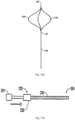
Figure 2 is a perspective view of the filter ofFigure 1 shown in an expanded position; -
Figure 3 is a side view of the delivery sheath (catheter) being inserted into the vena cava of a patient (via a femoral approach); -
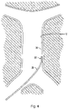
Figure 4 is a side view of the delivery sheath shown in contact with the wall of the vessel which occurs in certain instances of use, and the filter pusher shown advanced from the catheter; -
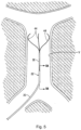
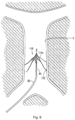
Figure 5 is a side view illustrating the centering wires of a first embodiment of the centering structure of the present invention, the centering structure exposed from the delivery sheath to center the distal opening of the delivery catheter; -
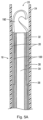
Figure 5A is an enlarged longitudinal cross-sectional view taken alongline 5A-5A ofFigure 5 ; -
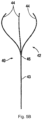
Figure 5B is a perspective view of the centering structure ofFigure 5 : -
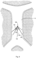
Figure 6 is a side view similar toFigure 5 showing the filter partially exposed from the delivery sheath but not yet expanded; -
Figure 7A is a side view similar toFigure 6 illustrating the filter fully deployed from the delivery sheath and in the expanded position; -
Figure 7B is a view similar toFigure 7A showing partial withdrawal of the centering wires into the filter pusher after full deployment of the filter; -
Figure 7C is an enlarged view of the area of detail designated inFigure 7A ; -
Figure 8 is a side view similar toFigure 7B illustrating the centering wires withdrawn into the delivery sheath; -
Figure 9 is a side view similar toFigure 8 illustrating the delivery sheath withdrawn and the filter substantially centered in the vessel in an expanded position; -
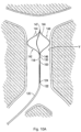
Figure 10A is a side view similar toFigure 6 illustrating an alternate embodiment of a centering structure of the present invention in the form of a basket, the centering structure shown in the expanded configuration and the filter show partially exposed from the delivery sheath but not yet expanded; -
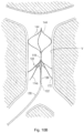
Figure 10B is a side view similar toFigure 10A showing the filter fully deployed from the delivery sheath and in the expanded position; -
Figure 10C is a perspective view of the centering structure ofFigure 10A ; -
Figure 11A is a perspective view of an alternate embodiment of the pusher and centering mechanism of the present invention, the centering mechanism shown in the retracted position; -
Figure 11B is a view similar toFigure 11A showing the centering mechanism advanced from the pusher; -
Figure 12A is a perspective view of another alternate embodiment of the pusher and centering mechanism of the present invention, the centering mechanism shown in the retracted position; -
Figure 12B is a view similar toFigure 12A showing the centering mechanism advanced from the pusher; and -
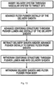
Figure 13 is a flow chart showing the method steps of the present disclosure. - Turning now to the drawings, wherein like reference numerals identify similar or like components throughout the several views, a method of implanting vein filters is disclosed. The filter is inserted via a femoral approach. In commonly assigned
United States patents 7,704,266 and8,162,972 various embodiments of filters are described with various structures. The delivery system of the present invention can be used to insert the filters disclosed in these patents as well as used to insert other filters. - As is common, the term "proximal" used herein refers to the part closer to the user, e.g., surgeon, and the term "distal" refers to the part further from the user. Thus, for example, the distal opening of the delivery sheath is the part further from the user as the proximal end extends from the patient's body for manipulation by the user.
- Turning initially to
Figures 5A and7A , thefilter delivery system 10 of the present invention has a delivery catheter orsheath 20 forming the outermost tube, afilter pusher 30 and a centering structure or centering mechanism 40 (or 140). For clarity, the centeringstructure 40 is not shown inFigure 5A . - Delivery sheath (catheter) 20 has a
distal tip 24 and adistal opening 26 at distal portion 22 (Figure 3 ). In a preferred embodiment, thesheath 20 can be composed of a Pebax material with a stainless steel braid embedded in the wall to increase its rigidity. A PTFE liner or coating is preferably provided on the inner surface of the sheath. Other materials and compositions are also contemplated. The sheath can have a hub (not shown) at a proximal portion for connection of a tube to allow for injection of cold saline, if desired, as described in the `266 patent which can be provided to maintain the filter in a relatively softer condition as it is in the martensitic state within the sheath. The tubing can also be utilized to inject other fluids. - The
filter pusher 30 has adistal tip 32 and alumen 34 extending therethrough (seeFigure 5A ). At a distal portion, but spaced proximally from thedistal tip 32, a step is formed to create ashoulder 38 to abut and support a filter thereon. Thepusher 30 is in contact with thefilter 100 by the abutment of theshoulder 38 and filter and deploys thefilter 100 either by distal movement of thepusher 30 to advance thefilter 100 from thesheath 20, by proximal movement of thesheath 20 to expose thefilter 100, or by movement of both thepusher 30 distally and thesheath 20 proximally. In either event, such relative movement of thepusher 30 andsheath 20 exposes thefilter 100 so it can move from its collapsed reduced profile delivery position or condition (seeFigure 1 ) contained with thesheath 20 to its expanded position or condition (Figures 2 and7A ) exposed from thesheath 20 to contact the vessel wall. - The
pusher 30 can be formed from a tube. In a preferred embodiment, thepusher 30 can be formed of Pebax material. The centering wires can be composed of stainless steel. Other materials and compositions of the pusher and wires are contemplated. A wire protruding beyond the distal end of thepusher 30 also can serve as a guidewire. The wire can also help keep the vessel engaging hooks of the filter separated during insertion. A marker band or other indicia can be provided to provide a visual indication of when the filter is at the distal end of the sheath (when the markings are adjacent a proximal end of a filter cartridge). Note in some embodiments, the centering wire can be attached to a hub of the pusher for slidable movement, e.g., by a control knob, such as in the embodiment described below. - The centering structure is designated by generally by
reference numeral 40 and has adistal portion 42 and a proximal portion extending outside the body for manipulation by the user.Distal portion 42 includes a plurality of centeringarms 44, joined atapex 46, bowing radially outwardly and terminating in free ends 48 (Figs. 5B and7A ). In a preferred embodiment, three centeringarms 44 are provided, however, a fewer or greater number of arms can alternatively be provided. The centeringstructure 40 is slidably positioned withinlumen 34 of thefilter pusher 30 and therefore moves, e.g., slides, relative to thepusher 30,sheath 20 andfilter 100. That is, the centeringstructure 40 is movable from a retracted (collapsed) position within thedelivery sheath 20 to an extended (advanced) position where thedistal portion 42 extends beyond thedistal tip 24 ofsheath 20 for movement from a collapsed to an expanded position. - In one embodiment, the centering
structure 40 is formed by a series of wires, e.g., anelongated wire 43 with centeringarms 44 formed of separate wires and attached to a distal portion of thewire 43 atapex 46 such as by welding, crimping, soldering, bonding or other known methods. Alternatively, theelongated wire 43 can form one of the centering arms and then additional centeringarms 44 can be attached to a region of theelongated wire 43 slightly proximal of its distal tip (as in the location of apex 46). The centering structure can alternatively be formed integrally from a monolithic wire or hypotube. The one piece structure can be laser cut and shape set. - The wires of the centering structure can be made of shape memory material such as Nitinol. In this manner, the wires are collapsed into a low profile position where the
arms 44 are substantially aligned with a longitudinal axis of thedelivery sheath 20 for delivery. When advanced from thesheath 20, the centering wires are exposed and return to their shape memorized expanded configuration (position) ofFigure 5 . Alternatively, they can be composed of spring material such as, stainless steel, and biased to an expanded position. Additionally, as an alternative, the centering wires could be moved to an expanded position when exposed from the sheath by an actuating mechanism, e.g., by actuating a wire or cable which when pulled bows thearms 44. - Note in the expanded position, the apex 46 can be exposed; alternatively the apex 46 can remain within the confines of the
sheath 20 orpusher 30. - As shown, when the centering wires expand, they have a transverse dimension sufficiently large to contact, preferentially circumferentially, the wall of the vessel, thereby keeping the
delivery sheath 20 anddistal tip 32 of thepusher 30 substantially centered within the vessel. It should be appreciated that the term "substantially centered" as used herein includes exactly centered within the vessel as well as slightly off center such as at an angle of up to about 30 degrees with respect to the longitudinal axis of the vessel, but preferably smaller. By keeping this angle closer to zero, centering of the delivery sheathdistal tip 24 anddistal opening 26, and therefore thefilter 100 when delivered, can better be achieved. - An alternate embodiment of the centering structure is illustrated in
Figures 10A-10C . The delivery sheath and filter pusher ofFigure 10A are identical to that of the embodiment ofFigures 1-9 , and therefore for brevity are not described in detail again. In short,filter pusher 130 is identical to filterpusher 30 and includes a distal tip and a shoulder (not shown) identical toshoulder 38. Delivery sheath orcatheter 120 is identical todelivery sheath 20 and includes adistal tip 122 and adistal opening 124 for exit of thefilter 100, identical todistal tip 22 andopening 24 ofdelivery sheath 20. - Centering
structure 140 differs from centeringstructure 40 in that it is a closed loop design. More specifically,distal portion 142 includes a plurality of centeringarms 144, joined atproximal apex 146 and at distal convergingregion 147. The connection atdistal region 147 provides more structural integrity. Centeringarms 144 bow radially outwardly between their proximal and distal fixed points. In a preferred embodiment, three centeringarms 144 are provided, however, a fewer or greater number of arms can alternatively be provided. The centeringstructure 140 is slidably positioned within a lumen of the filter pusher 130 (similar tolumen 34 of pusher 30) and therefore moves, e.g., slides, relative to thepusher 130,sheath 120 andfilter 100. That is, the centeringstructure 140 is movable from a retracted position within thedelivery sheath 120 to an extended (advanced) or exposed position where it extends beyond the distal tip ofsheath 120 for movement from a collapsed position to the expanded position ofFigures 10A and10B . - In one embodiment, the centering structure is formed by a series of wires, e.g., an elongated wire 143 (
Figure 10C ) with centeringarms 144 formed of separate wires and attached to a distal portion of thewire 143 atapex 146 such as by welding, crimping, soldering, bonding or other known methods. Thearms 144 are also attached at distal convergingregion 147 by welding, crimping, bonding, soldering or other known methods. Alternatively, theelongated wire 143 can form one of the centering arms and then additional centeringarms 144 are attached to a region of theelongated wire 143 slightly proximal of the distal tip (as in the location of apex 146) and at the distal tips (as in distal region 147). The centeringstructure 140 can alternatively be formed integrally from a monolithic wire or hypotube. The one piece structure can be laser cut and shape set. - The wires of the centering structure can be made of shape memory material. In this manner, the wires are collapsed into a low profile position where the
arms 144 are substantially aligned with a longitudinal axis of thedelivery sheath 120 for delivery. When advanced from thesheath 120, the wires are exposed and return to their shape memorized expanded configuration (position) ofFigures 10A and10B . Alternately, they can be composed of spring material such as stainless steel, and biased to an expanded position. Note in the expanded position, theproximal apex 146 can be exposed; alternatively the apex 146 can remain within the confines of thesheath 120 orpusher 130. An actuation mechanism, e.g., a wire or cable, can alternatively be used, e.g., pulled, to bow thearms 144 when exposed. - As shown, when the wires expand, they have a transverse dimension sufficiently large to contact the wall of the vessel, thereby keeping the
delivery sheath 120 anddistal tip 122 ofpusher 120 substantially centered within the vessel. Substantially centered as noted above includes exactly centered as well as slightly off center such as at an angle of up to 30 degrees with respect to the longitudinal axis, but preferably smaller. By keeping this angle closer to zero, centering of the opening of thedelivery sheath 120, and therefore thefilter 100 when delivered, can better be achieved. -
Figures 11A-12B illustrate alternate embodiments wherein the centering structure is attached to the pusher. In the foregoing embodiments, the centering mechanism is unattached to the pusher and slid within a lumen of the pusher. In the embodiments ofFigures 11A-12B the centering mechanism is attached at a proximal end to the pusher and is slid within the lumen of the pusher between retracted and advanced positions. - Turning to the embodiment of
Figures 11A and11B ,filter pusher 230 has aproximal portion 232 and adistal portion 234. A centeringmechanism 240 is slidingly received within a lumen of thepusher 230 for movement between a retracted position wherein the distal portion of the centeringstructure 240 is contained within the confines of thepusher 230 in a collapsed position and an extended exposed position (Figure 11B ) wherein the distal portion of the centeringstructure 240 is exposed from thepusher 230 to move to the expanded position. The centeringstructure 240 shown includes a series of wires with free ends as in the embodiment ofFigure 5 . Alternatively, the centering structure can be in the form of a basket or closed loop as in the structure ofFigure 10A . Hub or handle 242 of centeringmechanism 240 is grasped by the user and moved toward the hub or handle 236 offilter pusher 230 to advance the centeringstructure 240 with respect to thepusher 230 and sheath within which thepusher 230 is located. The centering wires are thereby slidably attached to thepusher 230, for example, within a plurality of channel guides inhub 236, each dimensioned to receive one of the centering wires. Alternatively, a single channel guide can be provided to receive only one of the centering wires, e.g., the central wire. In either event, the centering mechanism is attached (connected) to the pusher mechanism for slidable movement therein. - In the embodiment of
Figures 12A, 12B ,filter pusher 260 has aproximal portion 262 and adistal portion 264. A centeringmechanism 270 is slidingly received within a lumen of thepusher 260 for movement between a retracted position wherein the distal portion of the centering structure is contained within the confines of thepusher 260 in a collapsed position and an extended exposed position (Figure 12B ) wherein the distal portion of the centeringstructure 270 is exposed from thepusher 260 to move to the expanded position. The centeringstructure 270 shown includes a series of wires with free ends as in the embodiment ofFigure 5 . Alternatively, the centeringstructure 270 can be in the form of a basket or closed loop as in the structure ofFigure 10A .Actuator 274 moves withinelongated slot 265 of hub or handle 266 ofpusher 260. Theactuator 274 is attached to the centeringstructure 270 and is moved distally within theslot 265 to advance the centeringstructure 270 with respect to thepusher 260 and sheath in which thepusher 260 is positioned. - The centering structures described herein are self-expanding, e.g., composed of a shape memory material that automatically returns to the expanded position of
Figures 7A ,10A ,11B or 12B when exposed from the pusher and sheath. It is also contemplated that the structure can be controllably expanded with wires, cable or structure which can be actuated to expand the centering structure. In any of these versions, exposure from the confines of the walls of the pusher and/or sheath enables expansion of the centering structure. - The use of the filter implantation system will now be described. It should be understood that the method of use will be described in conjunction with the centering
structure 40 ofFigures 2-9 , it being understood that the centering structure ofFigures 10A-10C would be utilized in an identical manner. The centering structures ofFigures 11A-12B would also be used in similar manner, the difference being that the centering structure is slidably attached to the pusher, e.g., via a channel guide or a slot in the hub/handle, as it slides within the pusher lumen rather than being a separate component. Also, thedelivery system 10 is shown deliveringfilter 100 ofFigures 1 and 2 , it being understood that other filters can be delivered with the delivery system of the present application. - In use, once the
sheath 20 and dilator (not shown) are inserted through the femoral vein and advanced through the iliac vein into the inferior vena cava, the dilator is removed. Due to the anatomy of the particular patient's vena cava C, thesheath 20 may end up off center such as against the vessel wall V such that distal opening is close to the vessel wall (seeFigure 4 ). If thefilter 100 was then delivered from thesheath 20, it would not be centered on delivery. In accordance with the present invention, the advancement of the centering structure of the present invention moves thedistal end 22 anddistal opening 24 of thedelivery sheath 20 away from a position adjacent or tangent to the vessel wall V so thedistal opening 24 ofsheath 20 is more centered in the vessel, thus better ensuring thefilter 100 will be initially placed in a more centered position. - Note that during intravascular insertion of the
sheath 20 into the vena cava C,filter pusher 30,filter 100 and centeringstructure 40 positioned therein are fully covered bysheath 20 so as not to be exposed (Figure 3 ). With reference toFigures 4-9 , and to the flow chart ofFigure 13 , after thesheath 20 is advanced adjacent the vena cava, thepusher 30 is advanced distally within thedelivery sheath 20 to advance thefilter 100 distally adjacent a distal end of thesheath 20; however, thefilter 100 remains within thedelivery sheath 20 with a distal region of thepusher 30 exposed as shown inFigure 4 . - Next, the centering
structure 40 is advanced distally from the sheath 20 (Figure 5 ), sliding distally withinlumen 34 ofpusher 30. When the centeringarms 44 are exposed from thesheath 20, they move to the expanded configuration as they return to the shape memorized shape. The centeringarms 44 ensure thedistal opening 24 ofsheath 20 is moved away from the vessel wall V, which can be appreciated by comparingFigures 4 and5 . In this substantially centered position of thedistal tip 22 ofsheath 20, thefilter 100 is now ready for delivery to the vessel. - The
filter 100 is exposed from the sheath 20 (Figure 6 ) either by distal advancement of thepusher 30, retraction of thesheath 20, or movement of both thepusher 30 distally andsheath 20 proximally. When thefilter 100 is fully exposed (Figure 7A ), it returns to its shape memory position, with thevessel engaging hooks 172 engaging the vessel wall V to secure thefilter 100. Note that before fully deployed as in the position ofFigure 6 , the user can easily alter the position of placement of thefilter 100 by adjusting the longitudinal (i.e., distal or proximal) position by movement of the components. - Once the
filter 100 is fully deployed in the vessel, the centeringstructure 40 is then retracted proximally by the user, and the centeringarms 44 are thereby collapsed within thelumen 34 of thepusher 30 as it is withdrawn through thepusher 30 and into the sheath 20 (Figure 8 ). Once the centeringstructure 40 is withdrawn, thepusher 30 is retracted proximally within thesheath 20 and the components are removed from the vascular system, leaving thefilter 100 in place as shown inFigure 9 . - Note the Figures illustrate
filter 100 identical to the filter ofU.S. Patent No. 8,162,972 as one example of a filter that can be utilized with the delivery system of the present invention Thus,filter 100 is preferably formed from a single tube, and is preferably composed of shape memory material such as Nitinol. A plurality of cutouts are formed in thefilter 100, preferably by laser cutting, although other techniques are contemplated to thereby form struts 114. -
Filter 100, as shown in the expanded configuration ofFigure 2 , has a filter portion (section) 123 and a mounting portion (section) 130. As shown,filter 100 is generally bell-shaped in configuration.Filter 100 has a flared region and a convergingregion 121 at thefiltering portion 123. The transverse dimension of the filter at the flared (or mounting/anchoring) portion (region) 130 is greater than the transverse dimension at filtering portion (region) 123. Elongated struts 114 are spaced apart as shown and extend at an angle away from the longitudinal axis of thefilter 100 to provide a flare. - The
struts 114 offilter 100 terminate inhooks 172. In some embodiments, some struts can terminate in a hook larger than the hook of other struts. In some embodiments, thestruts 114 can terminate in alternating larger and smaller hooks such that everyother strut 114 would terminate in a small hook and the other struts (in between) would terminate in a larger hook. The penetratingtips 176 ofhooks 172 penetrate the tissue to retain the filter, preferably temporarily, and point toward the cranial end of the filter. - The six filter struts or strut
portions 114 extend longitudinally and then curve outwardly fromtubular portion 118, extend radially therefrom and divide into two connecting filter struts or strutportions adjacent strut 114. Thus, connectingstrut portion 114a of onestrut 114 interconnects with the connectingstrut portion 114b of an adjacent strut at joiningregion 114d. This forms closedgeometric shapes 125, preferably substantially diamond shaped in configuration. For clarity, not all of the identical parts are labeled in the drawings. - In the illustrated embodiment, preferably six struts are provided forming twelve interconnecting struts; however a different number of struts and closed geometric shapes can be provided. Note that although all six
struts 114 are shown interconnected, it is also contemplated that fewer than all the struts can be interconnected. Also, the strut width can vary as described with respect to the filters disclosed in the `972 patent. - After convergence of
strut portions region 114d, it transitions into elongated mountingstrut portions 114c which form the flared mounting or anchoringregion 130. The length of thestrut portions 114c in theanchoring region 130 can vary, with increased/decreased length increasing the flexibility/rigidity of the struts. The thickness of the strut portions can also vary to affect flexibility/rigidity. - The
tubular portion 118 is preferably in the form of aretrieval hook 192. In an alternate embodiment, instead of aretrieval hook 192, a ball or groove can be provided engageable by the retrieval snare (not shown) for retrieval of the filter. - Note that the
tubular region 118 has alumen 119 therethrough (seeFigure 7C ) through which thefilter pusher 30 can extend in the collapsed and in the expanded position of thefilter 100. Thus, as shown inFigure 7C , the centering structure 40 (or 140, 240 or 270), which extends through thepusher 30, would likewise extend through thetubular portion 118. In the collapsed position of the filter ofFigure 1 , thepusher 30 would likewise extend through the lumen of thetubular portion 118, and the centering structure 40 (or 140, 240, or 270) would also extend through thelumen 119 of thetubular portion 118. - After exposure of the
filter 100 by advancing thepusher 30 to eject thefilter 100 or retracting thesheath 20 with thepusher 30 held stationary, or relative movement of both thepusher 30 andsheath 20, thepusher 30 andsheath 20 are removed, enabling thefilter 100 to expand from its collapsed position ofFigure 1 and leaving the filter in place in the vena cava. - If it is later desired to remove the filter, the retrieval methods for the filter which are illustrated and described in detail in the '972 patent, such as a retrieval snare, can be utilized.
- If the
filter 100 is more centered in the vessel, the retrieval snare is better adapted to access and engage (grasp) the retrieval region, e.g., theretrieval hook 192, of thefilter 100. Also, if placement is more centered, removal can be easier because there will be less tissue ingrowth at the retrieval region. - Although according to the invention the pusher and sheath are utilized for inserting a vessel filter, the pusher and sheath can be utilized to insert other implants, including vascular implants such as a stent or valve, however this is not according to the invention.
- While the above description contains many specifics, those specifics should not be construed as limitations on the scope of the disclosure, but merely as exemplifications of preferred embodiments thereof. Those skilled in the art will envision many other possible variations that are within the scope of the disclosure as defined by the claims appended hereto.
Claims (9)
- A combination comprising an implantation system for a vascular implant and a vascular implant, the implantation system comprising: a sheath (20, 120) having a longitudinal axis, a lumen formed therein and a distal opening (26,124); a pusher (30, 130, 230, 260) positioned within the sheath, the pusher adapted to contact the vascular implant to deliver the implant from the sheath; and a sheath centering structure (40, 140, 240, 270) including an elongated portion (43, 143) and a plurality of arms (44, 144) extending from a distal portion of the elongated portion, the arms movable from a reduced profile position to an expanded position to move the sheath away from a vessel wall (V) to a more centered position, the centering structure movable in a longitudinal direction relative to the pusher,wherein either the plurality of arms (44) of the centering structure (40, 240, 270) are joined at an apex (46) and terminate in free ends (48) or the plurality of arms (144) of the centering structure (140) are joined at proximal and distal ends (146, 147) to form a basket-like structure,wherein the pusher (30, 130, 230, 260) comprises a lumen (34) and the centering structure (40, 140, 240, 270) is slidably positionable within the lumen of the pusher so that it is movable between a retracted position wherein the distal portion (42, 142) of the centering structure (40, 140, 240, 270) is contained within the confines of the pusher in a collapsed position and an extended exposed position wherein the distal portion (42, 142) of the centering structure is exposed from the pusher to move to the expanded position,wherein the implant is adapted to move from a reduced profile position within the sheath (20, 120) to an expanded placement position outside the sheath, the implant configured for deployment through the distal opening (26, 124) in the sheath for implantation in a patient's body, the implant (100) including a lumen (119) and the centering structure (40, 140, 240, 270) being movable through the lumen (119), and the implant comprising a vessel filter (100), the filter moving to an expanded configuration when deployed from the sheath (20, 120).
- A combination as claimed in claim 1, wherein the pusher (30, 130, 230, 260) includes a stepped portion forming a shoulder (38) to support the filter (100).
- A combination as claimed in any preceding claim, wherein the centering structure (40, 140, 240, 270) is movable independent of the pusher (30, 130, 230, 260).
- A combination as claimed in any preceding claim, wherein the pusher (30, 130) is slidably positioned within the sheath (20, 120).
- A combination as claimed in any preceding claim, wherein the plurality of arms (43, 44, 143, 144) comprise a plurality of wires.
- A combination as claimed in any preceding claim, wherein the plurality of arms (43, 44, 143, 144) are composed of shape memory material.
- A combination as claimed in any preceding claim, wherein the centering structure (240, 270) is attached to the pusher (230, 260).
- A combination as claimed in any one of claims 1 to 7, wherein the centering structure (40, 140) is unattached to the pusher (30, 130).
- A combination as claimed in any preceding claim, further comprising an actuator (242, 274) attached to the centering structure (40, 140, 240, 270) for advancing the centering structure.
Applications Claiming Priority (2)
| Application Number | Priority Date | Filing Date | Title |
|---|---|---|---|
| US201461988051P | 2014-05-02 | 2014-05-02 | |
| US14/678,938 US10159556B2 (en) | 2014-05-02 | 2015-04-04 | Method of inserting a vein filter |
Publications (2)
| Publication Number | Publication Date |
|---|---|
| EP2942034A1 EP2942034A1 (en) | 2015-11-11 |
| EP2942034B1 true EP2942034B1 (en) | 2023-03-29 |
Family
ID=53267210
Family Applications (1)
| Application Number | Title | Priority Date | Filing Date |
|---|---|---|---|
| EP15166102.2A Active EP2942034B1 (en) | 2014-05-02 | 2015-05-01 | Implantation system for inserting a vein filter |
Country Status (4)
| Country | Link |
|---|---|
| US (1) | US10159556B2 (en) |
| EP (1) | EP2942034B1 (en) |
| JP (1) | JP6553939B2 (en) |
| ES (1) | ES2943274T3 (en) |
Families Citing this family (4)
| Publication number | Priority date | Publication date | Assignee | Title |
|---|---|---|---|---|
| GB2552361B (en) * | 2016-07-21 | 2019-12-25 | Cook Medical Technologies Llc | Implantable medical device and method |
| CN114206260A (en) * | 2019-08-20 | 2022-03-18 | 霍利斯蒂克医疗公司 | Positioning device and method |
| US11786388B2 (en) | 2021-03-12 | 2023-10-17 | Cook Medical Technologies Llc | Endovascular delivery systems with radial orientation mechanisms |
| WO2023129178A1 (en) * | 2021-12-30 | 2023-07-06 | Bard Peripheral Vascular, Inc. | Vascular implant |
Citations (1)
| Publication number | Priority date | Publication date | Assignee | Title |
|---|---|---|---|---|
| US20080147160A1 (en) * | 2006-12-19 | 2008-06-19 | Sorin Biomedical Cardio S.R.L. | System for in situ positioning of cardiac valve prostheses without occluding blood flow |
Family Cites Families (20)
| Publication number | Priority date | Publication date | Assignee | Title |
|---|---|---|---|---|
| FR2573646B1 (en) | 1984-11-29 | 1988-11-25 | Celsa Composants Electr Sa | PERFECTED FILTER, PARTICULARLY FOR THE RETENTION OF BLOOD CLOTS |
| US4781173A (en) | 1985-06-28 | 1988-11-01 | Juha Ven | Evaporating device and electric supply station provided with such an evaporating device |
| US4832055A (en) | 1988-07-08 | 1989-05-23 | Palestrant Aubrey M | Mechanically locking blood clot filter |
| US5059205A (en) | 1989-09-07 | 1991-10-22 | Boston Scientific Corporation | Percutaneous anti-migration vena cava filter |
| US6059825A (en) | 1992-03-05 | 2000-05-09 | Angiodynamics, Inc. | Clot filter |
| US6214025B1 (en) | 1994-11-30 | 2001-04-10 | Boston Scientific Corporation | Self-centering, self-expanding and retrievable vena cava filter |
| US5893869A (en) | 1997-02-19 | 1999-04-13 | University Of Iowa Research Foundation | Retrievable inferior vena cava filter system and method for use thereof |
| US5984947A (en) | 1998-05-04 | 1999-11-16 | Scimed Life Systems, Inc. | Removable thrombus filter |
| US6007558A (en) | 1998-09-25 | 1999-12-28 | Nitinol Medical Technologies, Inc. | Removable embolus blood clot filter |
| US20070198078A1 (en) * | 2003-09-03 | 2007-08-23 | Bolton Medical, Inc. | Delivery system and method for self-centering a Proximal end of a stent graft |
| US7056286B2 (en) | 2003-11-12 | 2006-06-06 | Adrian Ravenscroft | Medical device anchor and delivery system |
| US8162972B2 (en) | 2004-01-22 | 2012-04-24 | Rex Medical, Lp | Vein filter |
| US7704266B2 (en) | 2004-01-22 | 2010-04-27 | Rex Medical, L.P. | Vein filter |
| US7232462B2 (en) * | 2004-03-31 | 2007-06-19 | Cook Incorporated | Self centering delivery catheter |
| US7794473B2 (en) * | 2004-11-12 | 2010-09-14 | C.R. Bard, Inc. | Filter delivery system |
| US7998164B2 (en) | 2005-03-11 | 2011-08-16 | Boston Scientific Scimed, Inc. | Intravascular filter with centering member |
| CA2633855A1 (en) | 2005-12-30 | 2007-07-12 | C.R. Bard Inc. | Embolus blood clot filter delivery system |
| US20070198050A1 (en) * | 2006-02-22 | 2007-08-23 | Phase One Medica, Llc | Medical implant device |
| CA2704292C (en) | 2007-11-02 | 2018-01-16 | Rex Medical, L.P. | Method of inserting a vein filter |
| FR2945440B1 (en) | 2009-05-14 | 2012-12-07 | Perouse Lab | TREATMENT DEVICE AND NECESSARY FOR TREATING A BLOOD CIRCULATION CONDUIT |
-
2015
- 2015-04-04 US US14/678,938 patent/US10159556B2/en active Active
- 2015-05-01 ES ES15166102T patent/ES2943274T3/en active Active
- 2015-05-01 EP EP15166102.2A patent/EP2942034B1/en active Active
- 2015-05-01 JP JP2015093780A patent/JP6553939B2/en active Active
Patent Citations (1)
| Publication number | Priority date | Publication date | Assignee | Title |
|---|---|---|---|---|
| US20080147160A1 (en) * | 2006-12-19 | 2008-06-19 | Sorin Biomedical Cardio S.R.L. | System for in situ positioning of cardiac valve prostheses without occluding blood flow |
Also Published As
| Publication number | Publication date |
|---|---|
| US20150313702A1 (en) | 2015-11-05 |
| JP6553939B2 (en) | 2019-07-31 |
| ES2943274T3 (en) | 2023-06-12 |
| JP2015211842A (en) | 2015-11-26 |
| EP2942034A1 (en) | 2015-11-11 |
| US10159556B2 (en) | 2018-12-25 |
Similar Documents
| Publication | Publication Date | Title |
|---|---|---|
| EP3534848B1 (en) | Stent graft delivery system with constricted sheath | |
| JP6553761B2 (en) | Reverse delivery device and method for prosthesis | |
| EP2252236B1 (en) | Vein filter | |
| EP2630933B1 (en) | Filter delivery system | |
| EP1894545B1 (en) | Multiple in vivo implant delivery device | |
| CN111971000A (en) | Prosthesis delivery system with end travel limiter and method of use thereof | |
| EP2777643B1 (en) | Implant introducer with helical trigger wire | |
| EP2942034B1 (en) | Implantation system for inserting a vein filter | |
| EP3064176B1 (en) | Prosthesis delivery device | |
| US20170189171A1 (en) | System and Method for Reducing Tricuspid Regurgitation | |
| WO2008130795A1 (en) | Prosthesis fixation apparatus and methods | |
| WO2013059241A1 (en) | Femoral removal vena cava filter | |
| EP2849677A2 (en) | Inversion delivery and method for a prosthesis | |
| US10376353B2 (en) | Method of inserting a vein filter |
Legal Events
| Date | Code | Title | Description |
|---|---|---|---|
| PUAI | Public reference made under article 153(3) epc to a published international application that has entered the european phase |
Free format text: ORIGINAL CODE: 0009012 |
|
| AK | Designated contracting states |
Kind code of ref document: A1 Designated state(s): AL AT BE BG CH CY CZ DE DK EE ES FI FR GB GR HR HU IE IS IT LI LT LU LV MC MK MT NL NO PL PT RO RS SE SI SK SM TR |
|
| AX | Request for extension of the european patent |
Extension state: BA ME |
|
| 17P | Request for examination filed |
Effective date: 20160511 |
|
| RBV | Designated contracting states (corrected) |
Designated state(s): AL AT BE BG CH CY CZ DE DK EE ES FI FR GB GR HR HU IE IS IT LI LT LU LV MC MK MT NL NO PL PT RO RS SE SI SK SM TR |
|
| RAP1 | Party data changed (applicant data changed or rights of an application transferred) |
Owner name: ARGON MEDICAL DEVICES, INC. |
|
| STAA | Information on the status of an ep patent application or granted ep patent |
Free format text: STATUS: EXAMINATION IS IN PROGRESS |
|
| 17Q | First examination report despatched |
Effective date: 20190214 |
|
| STAA | Information on the status of an ep patent application or granted ep patent |
Free format text: STATUS: EXAMINATION IS IN PROGRESS |
|
| GRAP | Despatch of communication of intention to grant a patent |
Free format text: ORIGINAL CODE: EPIDOSNIGR1 |
|
| STAA | Information on the status of an ep patent application or granted ep patent |
Free format text: STATUS: GRANT OF PATENT IS INTENDED |
|
| INTG | Intention to grant announced |
Effective date: 20221017 |
|
| GRAS | Grant fee paid |
Free format text: ORIGINAL CODE: EPIDOSNIGR3 |
|
| GRAA | (expected) grant |
Free format text: ORIGINAL CODE: 0009210 |
|
| STAA | Information on the status of an ep patent application or granted ep patent |
Free format text: STATUS: THE PATENT HAS BEEN GRANTED |
|
| RAP3 | Party data changed (applicant data changed or rights of an application transferred) |
Owner name: ARGON MEDICAL DEVICES, INC. |
|
| AK | Designated contracting states |
Kind code of ref document: B1 Designated state(s): AL AT BE BG CH CY CZ DE DK EE ES FI FR GB GR HR HU IE IS IT LI LT LU LV MC MK MT NL NO PL PT RO RS SE SI SK SM TR |
|
| REG | Reference to a national code |
Ref country code: GB Ref legal event code: FG4D |
|
| REG | Reference to a national code |
Ref country code: CH Ref legal event code: EP |
|
| REG | Reference to a national code |
Ref country code: DE Ref legal event code: R096 Ref document number: 602015082942 Country of ref document: DE |
|
| REG | Reference to a national code |
Ref country code: AT Ref legal event code: REF Ref document number: 1556149 Country of ref document: AT Kind code of ref document: T Effective date: 20230415 |
|
| REG | Reference to a national code |
Ref country code: IE Ref legal event code: FG4D |
|
| REG | Reference to a national code |
Ref country code: ES Ref legal event code: FG2A Ref document number: 2943274 Country of ref document: ES Kind code of ref document: T3 Effective date: 20230612 |
|
| REG | Reference to a national code |
Ref country code: LT Ref legal event code: MG9D |
|
| PG25 | Lapsed in a contracting state [announced via postgrant information from national office to epo] |
Ref country code: RS Free format text: LAPSE BECAUSE OF FAILURE TO SUBMIT A TRANSLATION OF THE DESCRIPTION OR TO PAY THE FEE WITHIN THE PRESCRIBED TIME-LIMIT Effective date: 20230329 Ref country code: NO Free format text: LAPSE BECAUSE OF FAILURE TO SUBMIT A TRANSLATION OF THE DESCRIPTION OR TO PAY THE FEE WITHIN THE PRESCRIBED TIME-LIMIT Effective date: 20230629 Ref country code: LV Free format text: LAPSE BECAUSE OF FAILURE TO SUBMIT A TRANSLATION OF THE DESCRIPTION OR TO PAY THE FEE WITHIN THE PRESCRIBED TIME-LIMIT Effective date: 20230329 Ref country code: LT Free format text: LAPSE BECAUSE OF FAILURE TO SUBMIT A TRANSLATION OF THE DESCRIPTION OR TO PAY THE FEE WITHIN THE PRESCRIBED TIME-LIMIT Effective date: 20230329 Ref country code: HR Free format text: LAPSE BECAUSE OF FAILURE TO SUBMIT A TRANSLATION OF THE DESCRIPTION OR TO PAY THE FEE WITHIN THE PRESCRIBED TIME-LIMIT Effective date: 20230329 |
|
| REG | Reference to a national code |
Ref country code: NL Ref legal event code: MP Effective date: 20230329 |
|
| REG | Reference to a national code |
Ref country code: AT Ref legal event code: MK05 Ref document number: 1556149 Country of ref document: AT Kind code of ref document: T Effective date: 20230329 |
|
| PG25 | Lapsed in a contracting state [announced via postgrant information from national office to epo] |
Ref country code: SE Free format text: LAPSE BECAUSE OF FAILURE TO SUBMIT A TRANSLATION OF THE DESCRIPTION OR TO PAY THE FEE WITHIN THE PRESCRIBED TIME-LIMIT Effective date: 20230329 Ref country code: NL Free format text: LAPSE BECAUSE OF FAILURE TO SUBMIT A TRANSLATION OF THE DESCRIPTION OR TO PAY THE FEE WITHIN THE PRESCRIBED TIME-LIMIT Effective date: 20230329 Ref country code: GR Free format text: LAPSE BECAUSE OF FAILURE TO SUBMIT A TRANSLATION OF THE DESCRIPTION OR TO PAY THE FEE WITHIN THE PRESCRIBED TIME-LIMIT Effective date: 20230630 Ref country code: FI Free format text: LAPSE BECAUSE OF FAILURE TO SUBMIT A TRANSLATION OF THE DESCRIPTION OR TO PAY THE FEE WITHIN THE PRESCRIBED TIME-LIMIT Effective date: 20230329 |
|
| PG25 | Lapsed in a contracting state [announced via postgrant information from national office to epo] |
Ref country code: SM Free format text: LAPSE BECAUSE OF FAILURE TO SUBMIT A TRANSLATION OF THE DESCRIPTION OR TO PAY THE FEE WITHIN THE PRESCRIBED TIME-LIMIT Effective date: 20230329 Ref country code: RO Free format text: LAPSE BECAUSE OF FAILURE TO SUBMIT A TRANSLATION OF THE DESCRIPTION OR TO PAY THE FEE WITHIN THE PRESCRIBED TIME-LIMIT Effective date: 20230329 Ref country code: PT Free format text: LAPSE BECAUSE OF FAILURE TO SUBMIT A TRANSLATION OF THE DESCRIPTION OR TO PAY THE FEE WITHIN THE PRESCRIBED TIME-LIMIT Effective date: 20230731 Ref country code: EE Free format text: LAPSE BECAUSE OF FAILURE TO SUBMIT A TRANSLATION OF THE DESCRIPTION OR TO PAY THE FEE WITHIN THE PRESCRIBED TIME-LIMIT Effective date: 20230329 Ref country code: AT Free format text: LAPSE BECAUSE OF FAILURE TO SUBMIT A TRANSLATION OF THE DESCRIPTION OR TO PAY THE FEE WITHIN THE PRESCRIBED TIME-LIMIT Effective date: 20230329 |
|
| PGFP | Annual fee paid to national office [announced via postgrant information from national office to epo] |
Ref country code: IT Payment date: 20230720 Year of fee payment: 9 Ref country code: GB Payment date: 20230727 Year of fee payment: 9 Ref country code: ES Payment date: 20230804 Year of fee payment: 9 |
|
| PG25 | Lapsed in a contracting state [announced via postgrant information from national office to epo] |
Ref country code: SK Free format text: LAPSE BECAUSE OF FAILURE TO SUBMIT A TRANSLATION OF THE DESCRIPTION OR TO PAY THE FEE WITHIN THE PRESCRIBED TIME-LIMIT Effective date: 20230329 Ref country code: PL Free format text: LAPSE BECAUSE OF FAILURE TO SUBMIT A TRANSLATION OF THE DESCRIPTION OR TO PAY THE FEE WITHIN THE PRESCRIBED TIME-LIMIT Effective date: 20230329 Ref country code: IS Free format text: LAPSE BECAUSE OF FAILURE TO SUBMIT A TRANSLATION OF THE DESCRIPTION OR TO PAY THE FEE WITHIN THE PRESCRIBED TIME-LIMIT Effective date: 20230729 |
|
| PGFP | Annual fee paid to national office [announced via postgrant information from national office to epo] |
Ref country code: FR Payment date: 20230725 Year of fee payment: 9 Ref country code: DE Payment date: 20230727 Year of fee payment: 9 |
|
| REG | Reference to a national code |
Ref country code: CH Ref legal event code: PL |
|
| REG | Reference to a national code |
Ref country code: DE Ref legal event code: R097 Ref document number: 602015082942 Country of ref document: DE |
|
| PG25 | Lapsed in a contracting state [announced via postgrant information from national office to epo] |
Ref country code: MC Free format text: LAPSE BECAUSE OF FAILURE TO SUBMIT A TRANSLATION OF THE DESCRIPTION OR TO PAY THE FEE WITHIN THE PRESCRIBED TIME-LIMIT Effective date: 20230329 |
|
| REG | Reference to a national code |
Ref country code: BE Ref legal event code: MM Effective date: 20230531 |
|
| PG25 | Lapsed in a contracting state [announced via postgrant information from national office to epo] |
Ref country code: MC Free format text: LAPSE BECAUSE OF FAILURE TO SUBMIT A TRANSLATION OF THE DESCRIPTION OR TO PAY THE FEE WITHIN THE PRESCRIBED TIME-LIMIT Effective date: 20230329 Ref country code: LU Free format text: LAPSE BECAUSE OF NON-PAYMENT OF DUE FEES Effective date: 20230501 Ref country code: LI Free format text: LAPSE BECAUSE OF NON-PAYMENT OF DUE FEES Effective date: 20230531 Ref country code: DK Free format text: LAPSE BECAUSE OF FAILURE TO SUBMIT A TRANSLATION OF THE DESCRIPTION OR TO PAY THE FEE WITHIN THE PRESCRIBED TIME-LIMIT Effective date: 20230329 Ref country code: CZ Free format text: LAPSE BECAUSE OF FAILURE TO SUBMIT A TRANSLATION OF THE DESCRIPTION OR TO PAY THE FEE WITHIN THE PRESCRIBED TIME-LIMIT Effective date: 20230329 Ref country code: CH Free format text: LAPSE BECAUSE OF NON-PAYMENT OF DUE FEES Effective date: 20230531 |
|
| PLBE | No opposition filed within time limit |
Free format text: ORIGINAL CODE: 0009261 |
|
| STAA | Information on the status of an ep patent application or granted ep patent |
Free format text: STATUS: NO OPPOSITION FILED WITHIN TIME LIMIT |
|
| REG | Reference to a national code |
Ref country code: IE Ref legal event code: MM4A |
|
| 26N | No opposition filed |
Effective date: 20240103 |