EP2942014A2 - Craniostat for acquiring extraoral dental radiographies - Google Patents
Craniostat for acquiring extraoral dental radiographies Download PDFInfo
- Publication number
- EP2942014A2 EP2942014A2 EP15163924.2A EP15163924A EP2942014A2 EP 2942014 A2 EP2942014 A2 EP 2942014A2 EP 15163924 A EP15163924 A EP 15163924A EP 2942014 A2 EP2942014 A2 EP 2942014A2
- Authority
- EP
- European Patent Office
- Prior art keywords
- bite
- craniostat
- patient
- base
- lever
- Prior art date
- Legal status (The legal status is an assumption and is not a legal conclusion. Google has not performed a legal analysis and makes no representation as to the accuracy of the status listed.)
- Granted
Links
- 238000002601 radiography Methods 0.000 title claims description 18
- 230000000903 blocking effect Effects 0.000 claims abstract description 18
- 238000000034 method Methods 0.000 claims abstract description 8
- 230000008878 coupling Effects 0.000 claims description 22
- 238000010168 coupling process Methods 0.000 claims description 22
- 238000005859 coupling reaction Methods 0.000 claims description 22
- 210000003484 anatomy Anatomy 0.000 claims description 13
- 210000004283 incisor Anatomy 0.000 claims description 13
- 239000000463 material Substances 0.000 claims description 12
- 239000004033 plastic Substances 0.000 claims description 4
- 210000001061 forehead Anatomy 0.000 description 32
- 210000003128 head Anatomy 0.000 description 16
- 230000007246 mechanism Effects 0.000 description 14
- 210000000214 mouth Anatomy 0.000 description 8
- 210000001738 temporomandibular joint Anatomy 0.000 description 7
- 210000002455 dental arch Anatomy 0.000 description 2
- 230000001419 dependent effect Effects 0.000 description 2
- 238000003745 diagnosis Methods 0.000 description 2
- 210000000613 ear canal Anatomy 0.000 description 2
- 238000000605 extraction Methods 0.000 description 2
- 230000003100 immobilizing effect Effects 0.000 description 2
- 238000004519 manufacturing process Methods 0.000 description 2
- 230000000284 resting effect Effects 0.000 description 2
- 238000004846 x-ray emission Methods 0.000 description 2
- 238000013459 approach Methods 0.000 description 1
- 230000004323 axial length Effects 0.000 description 1
- 238000009414 blockwork Methods 0.000 description 1
- 238000004140 cleaning Methods 0.000 description 1
- 230000000295 complement effect Effects 0.000 description 1
- 238000007408 cone-beam computed tomography Methods 0.000 description 1
- 238000005516 engineering process Methods 0.000 description 1
- 230000001747 exhibiting effect Effects 0.000 description 1
- 210000000887 face Anatomy 0.000 description 1
- 239000012530 fluid Substances 0.000 description 1
- 239000006260 foam Substances 0.000 description 1
- 238000003384 imaging method Methods 0.000 description 1
- 238000003780 insertion Methods 0.000 description 1
- 230000037431 insertion Effects 0.000 description 1
- 210000001847 jaw Anatomy 0.000 description 1
- 210000004373 mandible Anatomy 0.000 description 1
- 239000002184 metal Substances 0.000 description 1
- 239000007769 metal material Substances 0.000 description 1
- 210000003455 parietal bone Anatomy 0.000 description 1
- 229920001296 polysiloxane Polymers 0.000 description 1
- 210000003625 skull Anatomy 0.000 description 1
- 239000007779 soft material Substances 0.000 description 1
- 210000004357 third molar Anatomy 0.000 description 1
Images


Classifications
-
- A—HUMAN NECESSITIES
- A61—MEDICAL OR VETERINARY SCIENCE; HYGIENE
- A61B—DIAGNOSIS; SURGERY; IDENTIFICATION
- A61B6/00—Apparatus or devices for radiation diagnosis; Apparatus or devices for radiation diagnosis combined with radiation therapy equipment
- A61B6/50—Apparatus or devices for radiation diagnosis; Apparatus or devices for radiation diagnosis combined with radiation therapy equipment specially adapted for specific body parts; specially adapted for specific clinical applications
- A61B6/51—Apparatus or devices for radiation diagnosis; Apparatus or devices for radiation diagnosis combined with radiation therapy equipment specially adapted for specific body parts; specially adapted for specific clinical applications for dentistry
-
- A—HUMAN NECESSITIES
- A61—MEDICAL OR VETERINARY SCIENCE; HYGIENE
- A61B—DIAGNOSIS; SURGERY; IDENTIFICATION
- A61B6/00—Apparatus or devices for radiation diagnosis; Apparatus or devices for radiation diagnosis combined with radiation therapy equipment
- A61B6/04—Positioning of patients; Tiltable beds or the like
-
- A—HUMAN NECESSITIES
- A61—MEDICAL OR VETERINARY SCIENCE; HYGIENE
- A61B—DIAGNOSIS; SURGERY; IDENTIFICATION
- A61B6/00—Apparatus or devices for radiation diagnosis; Apparatus or devices for radiation diagnosis combined with radiation therapy equipment
- A61B6/50—Apparatus or devices for radiation diagnosis; Apparatus or devices for radiation diagnosis combined with radiation therapy equipment specially adapted for specific body parts; specially adapted for specific clinical applications
- A61B6/501—Apparatus or devices for radiation diagnosis; Apparatus or devices for radiation diagnosis combined with radiation therapy equipment specially adapted for specific body parts; specially adapted for specific clinical applications for diagnosis of the head, e.g. neuroimaging or craniography
-
- F—MECHANICAL ENGINEERING; LIGHTING; HEATING; WEAPONS; BLASTING
- F16—ENGINEERING ELEMENTS AND UNITS; GENERAL MEASURES FOR PRODUCING AND MAINTAINING EFFECTIVE FUNCTIONING OF MACHINES OR INSTALLATIONS; THERMAL INSULATION IN GENERAL
- F16B—DEVICES FOR FASTENING OR SECURING CONSTRUCTIONAL ELEMENTS OR MACHINE PARTS TOGETHER, e.g. NAILS, BOLTS, CIRCLIPS, CLAMPS, CLIPS OR WEDGES; JOINTS OR JOINTING
- F16B2/00—Friction-grip releasable fastenings
- F16B2/02—Clamps, i.e. with gripping action effected by positive means other than the inherent resistance to deformation of the material of the fastening
- F16B2/18—Clamps, i.e. with gripping action effected by positive means other than the inherent resistance to deformation of the material of the fastening using cams, levers, eccentrics, or toggles
Definitions
- the present invention relates to extraoral dental digital radiographic apparatuses, wherein both the X-ray source and the X-ray sensor are placed outside patient's oral cavity.
- the present invention relates to a device for immobilizing patient's head during radiographic acquisitions, i.e. a craniostat according to the preamble of claim 1.
- Extraoral dental radiographic apparatuses can produce two kinds of radiographies: bi-dimensional (2D) radiographies, or volumetric (3D) radiographies.
- panoramic radiographies In the field of bi-dimensional radiographies, panoramic radiographies and teleradiographies are included.
- Panoramic radiography also known as orthopantomography produces a radiographic image of a curved plan, known as Welander's curve, approximating patient jaws, with blurring of the anatomical structures laying outside a narrow layer around the predesigned curved plane. This technology has been known since the '50s.
- Teleradiography is a projective radiographic technique, producing radiographic images of the skull or of other anatomical areas from different projections, with minimum magnification and geometrical distortion. Usually two perspectives are represented, latero-lateral and anteroposterior.
- Cone beam volumetric radiography also known as CBCT is the acquisition, from different projection angles, of a series of bi-dimensional radiographic images which will be processed post-acquisition to reconstruct three-dimensional volumes.
- Extraoral radiographies are performed through known apparatuses, wherein typically at the two ends of a C-arm an X-ray source and an X-ray sensor are positioned, respectively, while a patient is placed between them.
- the X-ray source and sensor rotate around patient's head, which is kept still by a positioning device (craniostat).
- the movements that mechanical parts have to perform in order to get this result is called trajectory.
- the patient In order to get a good image, the patient must remain still during the acquisition time, that is during X-ray emission. On the other hand, it is easy to realize that the patient will stand still if she/he is comfortable, while if she/he is uncomfortable, or under stress, there are more probabilities for her/him to move.
- the craniostat should be as transparent as possible to X-rays, in order not to create artefacts which might reduce the diagnostic validity of the radiographic image. This has an impact on materials (no metallic materials can be used), but also on thicknesses, in that with increasing thickness even a radiolucent material begins to appear in radiographies. However, the reduction of thickness bears the risk of making the craniostat not rigid enough to ensure the solidity of the object and therefore patient's immobility.
- the contact parts of the craniostat must be disposable, or must be disinfectable between patients.
- the craniostat must allow the positioning of any patient: from paediatric patients to adult patients of big dimensions (99 percentile), and therefore must fit cranial measures presenting a wide variability (cranium diameter going from 14 cm to 18.5 cm).
- the extraoral dental radiographic apparatus In order to perform all the kinds of acquisitions which will be described in the following, the extraoral dental radiographic apparatus must be able to perform an ample number of different trajectories, and therefore the C-arm needs wide possibilities of movement around the patient.
- Trajectories have a generically circular or semi-circular shape, and it is therefore possible to define an "anti-collision cylinder" wherein neither X-ray source nor X-ray sensor can enter. Once defined an as small as possible anti-collision cylinder, both patient's head and craniostat must be contained inside it. It is therefore important that the craniostat is not bulky, so as to not constitute a limit for the trajectories.
- the craniostat In order to perform all the kinds of acquisition, especially teleradiographies, the craniostat has to be removed by X-ray path during the acquisition.
- the craniostat must allow a rapid and easy positioning of the patient by the professional human operator.
- Frankfurt plane which is a virtual plane passing through the inferior margin of the left orbit and the upper margin of each ear canal or external auditory meatus, immediately under the eye.
- Document US3936641 shows a positioning device for the head of a patient, in an apparatus for carrying out x-ray imaging. This craniostat does not show any bite, but the chin part of the patient is held in place by means of an arched chin rest.
- Aim of the present invention is providing a craniostat according to the above-quoted requirements, and which is of easy and economic manufacturing.
- the craniostat of the present invention is an integral object removably mounted on a specific support.
- the craniostat can be removed from said support, the removal being necessary during apparatus calibration and when teleradiographies are performed, as the craniostat is on the X-ray path (during teleradiographies the patient is blocked by another specific positioning device).
- the removing system must be simple and ergonomic for the operator, without undermining the necessary stability of the craniostat while it is in use.
- the coupling craniostat-support is realized with four pins which enter into four specific pin holes, one of which is longer than the others.
- craniostat can be subdivided into two portions:
- the lower portion of the craniostat comprises a supporting base for fixed or removable parts supporting different anatomic portions of the patient: rods supporting the upper portion of the craniostat, bite for the patient, chin support and other supports for different kinds of acquisitions.
- the lower base exhibits a recess towards the patient which is useful to acquire temporomandibular radiographies with both open and closed mouth.
- the lower base brings a bite having a height adjustable with respect to the base itself, correspondently to the needs of the specific acquisition needs and of patient's anatomy.
- the bite is height adjustable, and must be blocked at different heights.
- the bite can be continuously blocked at any height comprised between a minimum and a maximum (no pre-defined heights are present); for the bite-wing position only a pre-defined height is required.
- a small lever loaded by a spring indicates to the operator that the correct height was reached, without the need of indications on bite stem, like notches or coloured points of reference, which must be optically checked by the operator.
- the shape of the bite must be such at to ensure the smallest radiopacity; for this an arch shape was chosen, instead of a L-shape.
- the bite is used with a disposable cover for patient's hygiene, which is changed between patients; the bite is made of only one material, and is optionally autoclavable.
- the thickness of the material is as low as possible to ensure radiolucency, so as not to visualize the bite in the radiographic image.
- bite height is free; once the desired height was reached, the bite is blocked in the correct position through a lever positioned in the anterior part of the base.
- the bite until it is blocked, freely rotates in its seat, and this facilitates patient's positioning; however, when the bite is blocked in its correct height through its lever, is also automatically centred, so as to ensure that the patient is correctly positioned on the sagittal plane.
- the bite is blocked in the desired position through a lever, which, in addition to blocking the bite in the vertical direction, sagittally rotates the bite itself bringing it in a position symmetrical to the sagittal plane.
- the distance between the bite point and the rods is the shortest possible to allow the passage of the sensor without collision, but at the same time ensuring that rods are outside the acquisition plane, therefore in the blurred area.
- the chin support is also removable, to allow the maximal versatility of use of the craniostat (open mouth acquisition of temporomandibular joints).
- the coupling occurs through two pins, having the same length.
- the craniostat can be made of plastic materials, so ensuring radiolucency and preventing scattering artefacts due to metal.
- the plurality of supporting points for patient's head makes the positioning comfortable for the patient, and nonetheless very stable.
- the difference in diameter between a very big patient and the anti-collision cylinder is very limited, about 2-3 cm. Therefore, the limited thickness of the craniostat allows both to perform complex trajectories, and to obtain the maximal radiolucency of the craniostat in radiographies.
- the craniostat of the present invention a positioning philosophy was chosen that is different from the system making use of an electromagnet or pre-loaded springs.
- the craniostat holding capability is in the first case dependent on how much the operator tightens the adjusting mechanisms, in the second case on how much the spring is pre-loaded. Therefore, such objects are very stable but also very rigid, and not very comfortable for the patient.
- the adjusting systems work so that first the operator approaches the contact points to the patient, and then blocks the contact point in that position, allowing an adjustment that is much more respectful of patient's anatomy and comfort. The operator gets a tactile and/or acoustic feed-back for each adjustment.
- Figure 1 shows a typical extraoral radiographic apparatus 1 of the known art, comprising an X-ray source 7 projecting a collimated bundle of X-rays through a (not shown) patient; a bi-dimensional X-ray sensor 8 positioned so as to measure the intensity of X-rays after they crossed the patient; a device 5 for the positioning of the patient interposed between X-ray source and sensor; a C-arm 6 on whose ends said X-ray source 7 and sensor 8 are supported; a mechanical system allowing the rotation and the translation of said C-arm around the patient, in order to acquire radiographic images from various positions; (not shown) electronic circuits such as to adjust and synchronize the working of the various parts of the apparatus.
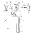
- the position of the C-arm 6 can be adjusted to patient's height thanks to column 4 sliding on columns 3 fixed to the ground through base 2.
- the extraoral apparatus 1 may further comprise an arm 11 for teleradiography, to which a further patient's positioning device 13 is fixed, and a teleradiography sensor 15 is removably fixed on support 12.
- the craniostat 20 of the present invention is shown in Figure 2 disconnected from the apparatus 1 for acquiring radiographs; when it is connected it is in the position indicated with 5 in Figure 1 .
- the craniostat is placed on its specific support 30, which is part of the patient positioning device 5; the support 30 is shown in Figure 3 .
- Figure 4 shows the coupling between the lower portion 22 of the craniostat 20 and the support 30 connecting it to the apparatus 1.
- the coupling craniostat-support is realized through four pins 45, 46 which fit in their specific holes; one of the pins is longer than the others.
- the longer pin 46 is the one ensuring the best coupling precision, thanks to minimal coupling tolerance in the respective hole, while the correct positioning and stability of the craniostat are ensured by the remaining shorter pins 45.
- the choice of different coupling tolerances is linked to production cost and to the ease of coupling by the human operator.
- a spring-loaded pressure plate acts on the pins, so as to inform the human operator that the perfect coupling craniostat-support has been reached, which ensures maximum stability.
- the spring is compressed when the pin 46 is inserted in its hole for its complete length, and its operation gives the operator an acoustic (metallic click) and tactile (friction of the vertical movement) feed-back.
- the spring-loaded pressure plate is indispensable on the long pin 46 and optional on the three short pins 45.
- the craniostat 20 can be subdivided into an upper portion 21 and a lower portion 22.
- a couple of rods 23 connects the two portions 21 and 22.
- the lower portion of the craniostat will be described.
- the lower portion of the craniostat 20 is shown resting on support 30 and complete with chin rest 52.
- the lower portion 22 of the craniostat has a fixed base 41, provided with a lever 54 for blocking bite 53.
- the chin rest 52, and the bite 54 are removable according to the needs of the different acquisitions.
- the distance d between bite 54 in its blocked position and rods 23, indicated with a dotted line, is the widest possible so as rods 23 are out from the focal trough, but inside the anti-collision cylinder. In the preferred embodiment, said distance d is 55 mm.
- the bite 54 When the lever 53 is its unblocked position (in one of its two extreme positions, e.g. totally on the left), the bite 54 is free to vertically slide in the direction indicated by the linear double arrow, and to pivot in the direction indicated by the arched double arrow.
- This disposition is particularly comfortable when positioning a patient, in that the human operator firstly unblocks the bite 54 through the lever 53 and rotates it toward one of the two rods 23, rests patient's chin on chin rest 52, and then positions the bite 54 inside patient's oral cavity vertically adjusting it.
- the bite 54 When the operator blocks the position of the bite 54 through lever 53, e.g. bringing the lever totally on the right, the bite 54 is automatically positioned in its correct sagittal position, thanks to its particular shape.
- Figure 6 shows the mechanism, contained in the base 41, for blocking the bite 54.
- the stem 61 When the lever 53 is in its unblocked position, the stem 61 is in the portion having a circular section of the hole 63 of block 62, and is therefore free to move.
- the block 62 When the lever 53 is in its blocked position, the block 62 is pushed by a cam 65 so as to compress spring 64 in the direction of the arrow.
- the portion of the hole 63 having a triangular section is coupled to the stem 61, blocking it through friction.
- the stem 61 has in its turn a triangular transversal section, which allows both a higher friction, and an auto-centring on the sagittal plane.
- the axis A-A' shows the plane of the section shown in Figure 6a and allows to better appreciate the functioning of the block.
- the hole 63 has a section partly rounded and partly triangular, and the stem 61 has a triangular section which, when blocked, is coupled to the triangular portion of hole 63.
- the cam 65 is rotated and the spring 64 pushes in a direction contrary to the arrow the block 62, freeing the coupling between the triangular section of hole 63 and of stem 61 of bite 54.
- triangular section means that a part of the delimitation surfaces of the hole, at least for a certain axial length of the bite itself, have two walls which are opposed and converging. These walls are preferably symmetrically positioned with respect to a plane containing the longitudinal axis and a diameter of hole 63, such diameter coincides with a bisector of the angle defined by the two opposed converging walls.
- the remaining part of the perimetral delimitation surface of hole 63 can have any shape, and in this embodiment is cylindrical, i.e. having circular section; the wedge-shaped portion and the cylindrical portion are seamlessly joined together.
- the stem 61 has at least for a part of its axial, longitudinal extension a section substantially analogous to the section of hole 63, but dimensionally smaller and such that said stem 61 can slide both axially, in order to adjust the bite height with respect to the chin rest, and radially, i.e. in the direction of wedging a portion of the surface of the stem itself.
- the stem has two opposed and converging walls like a wedge, preferably with the same angle of the converging walls of hole 63, also in the opposed direction of said walls, moving from the converging walls of hole 63.
- the tightening means i.e. the mechanism controlled by the lever, thrust the stem in the wedging direction of the wedge-shaped portion of said stem into the wedge-shaped portion of the hole 63, blocking said stem both in the axial direction and in its rotation around its own longitudinal axis.
- both the stem 61 and its housing hole 63 have both complementary surfaces of contact having a pre-defined angular orientation and a shape so as in tightening conditions of stem 61 in the hole 63: said surfaces come into contact and define a pre-defined angular orientation of the stem around its own axis.
- Figure 7 shows a further detail of bite 54, which is particularly useful when acquiring bite-wing radiographies, which requires the positioning of the patient at a pre-defined height.
- the stem 61 of bite 54 has a particular profile of its transversal section.
- the upper part has a substantially circular section, while about halfway its lower section becomes triangular or wedge-shaped, for the reasons explained above linked to bite auto-centring.
- the stem 61 has a horizontal recess 71.
- Inside base 41 there is also a small lever 72 pre-loaded by a spring 73, which constantly frictions, in a virtually undetectable way, against the stem 61.
- Figure 7a shows the sagittal section of bite 54 which is kept between patient's teeth
- Figure 7b shows a top view of the bite 54 end.
- the portion that the patient bites with her/his incisors is small.
- the anterior part 74 of the portion is shown, which has a net, not blunted angle, so as to ensure the stop of upper 101 and lower incisors 102, which thus lie on the same plane; in this way a panoramic image results with an as correct as possible focusing.
- the posterior part 75 is tapered and rounded to better fit patient's anatomy (Welander curve 103) and to reduce the thickness of the material crossed by X-rays. This tapering, indicated with angle ⁇ in Figure 7b , must nonetheless ensure a resting position sufficient for anterior teeth.
- said angle ⁇ is comprised between 15 and 25 degrees.
- the bite 54 it was optimized to the aim of not appearing in the radiographies, yielding an artefact. Therefore, it was built using a radiolucent plastic material. Moreover, its profile has a particular shape which allows to minimize the quantity of plastic material. As can be seen in Figure 7c , in the lower side of the arched part 76 of the bite there is a recess 77 which reduces the thickness of the bite. With the aim of maintaining its rigidity, in the bite 54 there are two ribs 78 distinct in the bite distal part, which unite in the proximal part; on said ribs the stress transmitted by the patient is discharged.
- FIG 8 the coupling between chin rest 52 and base 41 is shown.
- the coupling occurs through two pins 81 and 82 having the same length; the pin 81 is inserted in a hole which has a reduced coupling tolerance.
- the fact that the coupling of pin 82 is looser allows the operator to easily insert it into its hole, while the precise coupling of pin 81 ensures the stability of the assembly.
- the weight of patient's head is sufficient to ensure the desired immobility, and therefore there is no spring-loaded pressure plate or similar devices.
- the presence of chin rest 52 is required in practically all acquisitions, but those of temporomandibular joints, during which chin rest 52 must be removed.
- chin rest 52 when chin rest 52 is removed, it is replaced by nose support 90, on which the patient rests her/his anterior nasal spine as shown in Figure 9 .
- the nose support 90 is inserted through two pins 91 and 92 in the same holes in which pins 81 and 82 of chin rest 52 are inserted, with the same tolerances discussed above.
- a recess 93 on the craniostat 20 base 41, allows her/him to easily open and close her/his mouth, without the need of re-positioning the patient.
- the upper portion of the craniostat has to keep the patient in the desired position, and the most suitable points to this aim are considered patient's forehead (on the sagittal plane), the lateral parts of the cranium (laterally), the terminal part of the parietal bone (posteriorly).
- the upper portion 21 of the craniostat comprising a forehead rest 105 and two mobile rests 107 for the lateral portions of cranium.
- the upper portion 21 is height adjustable on rods 23.
- the upper portion 21 comprises a crossbeam 104, having holes which allow to slide on rods 23. On crossbeam 104 there is a hole in which the forehead rest 105 is slidingly inserted.
- two small arms 106 which can pivot independently of one another, so as to adjust to the width of patient's cranium, accommodating also patients having remarkable dissymmetry.
- At the end of the two arms 106 there are two small arches 107, free to independently pivot around their insertion fulcrum. Both the arms 106 and the small arches 107 have their fulcrum so as to rotate around axes substantially parallel to a vertical or longitudinal axis of patient's head.
- each arch 107 there are two, optionally removable, rubber tips or pads 108, which rest on patient's skin.
- a slot 109 which allows to insert an optional (not shown) band, generally in a soft, bendable material, which surrounds the posterior part of patient's head, so as to further immobilize her/him.
- the use of the band is optional and left to the preference of the individual human operator.
- the forehead rest 105 sliding inside the (not shown) crossbeam 104 is shown.
- the forehead rest 105 has a particular arched profile, and ends in a wide rest surface 111, on which a small, optionally removable, cushion is fixed, made of a soft material (silicone, gum, foam) to improve patient's comfort.
- the profile of rest surface 111 is slightly arched in order to better fit patient's anatomy.
- the forehead rest 105 is free to slide inside the crossbeam 104, with two, one upper and one lower, limits.
- the lower limit is due to the fact that rest 111 is larger than the seat inside which forehead rest 105 slides.
- the upper limit is due to the end-of-stroke device 112, which is provided with two small teeth 113 which perform a slight constant friction on the forehead rest 105.
- the joint between teeth 113 and recesses 114 in the upper end of forehead rest 105 prevents the accidental extraction of the forehead rest 105.
- the assembly is designed so that an intentional pressure allows the extraction of the forehead rest 105 from its seat in the crossbeam 104 for cleaning, replacement, etc.
- Optional intermediate recesses can correspond to pre-defined positions of the forehead rest 105 if needed for particular acquisitions.
- Figure 12 shows a sagittal section of the forehead rest 105 inserted in its seat in the crossbeam 104. It shows the working mechanism of the forehead rest 105. The working mechanism is highlighted in Figure 12 through the bold and dotted arrows. Basically, when the patient rests her/his forehead on the rest surface 111, she/he applies a given pressure, represented by bold arrow c. The vector of the force has two components, shown by a and b arrows, in the two points A and B, thus blocking the sliding of the forehead rest 105 due to friction.
- the forehead rest 105 there are two recesses in the points E and F so as to precisely indicate to the human operator where to apply pressure when she/he wishes to height adjust the position of the forehead rest 105. It is apparent from the profile of the forehead rest 105 that its height adjustment occurs in the direction of thickness, too.
- Figure 13 shows a detail of the blocking mechanism of arm 106, inside which there is inserted a ferrule or screw nut 134 leading the block screw 133.
- the arms 106 (not shown in this Figure) have their fulcrum on a pivot 131, and this allows to adjust them according to the width of patient's cranium, width exhibiting a wide variability.
- the blocking mechanism When the blocking mechanism is activated, the block screw 133 enters into contact with block 132, integral with crossbeam 104, generating the friction needed for blocking the system.
- the block screw 133 is rotationally inserted in the ferrule 134, which is connected with the lever 135, protruding from the structure itself in order to be used by the human operator as controls through rotation of ferrule 134.
- the rotation of the ferrule thanks to the thread and the fact that it is essentially stationary, entails an axial movement of the screw.
- the lever 135 can rotate between two extreme positions, the first of which is shown in Figure 10 (upwards) and the second of which is shown in Figure 15b (outwards).
- the lever 135 When the lever 135 is in the upward position as shown in Figure 10 , the arm 106 is free to rotate around its pivot 131 without friction.
- the lever 135 when the lever 135 is rotate downwardly, it will block, meeting block 132, in any position comprised between the two extreme positions, position which is proportional to the width of patient's cranium.
- the human operator after accommodating the patient inside the craniostat 20, adjusts the position of the arms 106 according to patient's anatomy, and then rotates the levers 135 downwardly.
- Figure 14 shows in detail the working of the block mechanism of arms 106.
- the Figure shows a section along the rotation axis of the system ferrule 134-screw 133.
- the distance between the block screw 133 and the block 132 varies proportionally to patient's anatomy. When the patient's cranium is small, and the distance screw 133-block 132 is therefore great, to reach the block a turn of the screw 133 will be needed which is wider than the turn of the screw needed with a big cranium, and this is ensured by the length of the thread of screw 133.
- the section of the thread 141 is substantially a scalene trapezoid wherein the angles of the oblique surfaces working with the ferrule are different.
- Figure 14 shows the preferred embodiment, based on a surface coupling system which blocks the moving parts by friction. However, based on the same principle there are many other possible embodiments, some of which are e.g. shown in Figures 14a and 14b .
- Figure 14a shows a wedge device, wherein the movement of the rigid block 133a, conceptually equivalent to screw 133, is blocked by a wedge 142. According to the distance rigid block 133a-block 132a, the wedge 142 will be lowered of a variable quantity, proportional to patient's anatomy.
- Figure 14b shows a saw tooth device, wherein the movement of the rigid block 133b, conceptually equivalent to screw 133, is blocked by a specular saw tooth 143.
- the disadvantage of this configuration is that it works only discontinuously, and does not allow a continuous adjustment.
- Figures 15a and 15b show the horizontal section of a cranium of a very big patient 100a and of a very small patient 100b, respectively.
- the comparison between the two Figures allows to appreciate the different position of forehead rest 105 and of arms 106.
- forehead rest 105 is positioned upwardly, and thanks to its arched profile, protrudes little with respect to crossbeam 104.
- the arms 106 are in their maximal outward extension, and therefore the levers 135 are very near to their upward unblock position.
- forehead rest 105 is positioned downwardly in its end-of-stroke position, and protrudes markedly towards patient's forehead, while the arms 106 are in their inward maximal extension, and therefore the levers 135 are in their extreme block position, protruding outwardly.
Landscapes
- Health & Medical Sciences (AREA)
- Life Sciences & Earth Sciences (AREA)
- Engineering & Computer Science (AREA)
- Medical Informatics (AREA)
- Heart & Thoracic Surgery (AREA)
- Pathology (AREA)
- Veterinary Medicine (AREA)
- Public Health (AREA)
- Physics & Mathematics (AREA)
- General Health & Medical Sciences (AREA)
- Biophysics (AREA)
- High Energy & Nuclear Physics (AREA)
- Animal Behavior & Ethology (AREA)
- Nuclear Medicine, Radiotherapy & Molecular Imaging (AREA)
- Optics & Photonics (AREA)
- Surgery (AREA)
- Radiology & Medical Imaging (AREA)
- Biomedical Technology (AREA)
- Molecular Biology (AREA)
- Oral & Maxillofacial Surgery (AREA)
- Dentistry (AREA)
- General Engineering & Computer Science (AREA)
- Neurosurgery (AREA)
- Neurology (AREA)
- Mechanical Engineering (AREA)
- Apparatus For Radiation Diagnosis (AREA)
- Dental Tools And Instruments Or Auxiliary Dental Instruments (AREA)
Abstract
Description
- The present invention relates to extraoral dental digital radiographic apparatuses, wherein both the X-ray source and the X-ray sensor are placed outside patient's oral cavity. In particular, the present invention relates to a device for immobilizing patient's head during radiographic acquisitions, i.e. a craniostat according to the preamble of
claim 1. - Extraoral dental radiographic apparatuses can produce two kinds of radiographies: bi-dimensional (2D) radiographies, or volumetric (3D) radiographies.
- In the field of bi-dimensional radiographies, panoramic radiographies and teleradiographies are included.
- Panoramic radiography (also known as orthopantomography) produces a radiographic image of a curved plan, known as Welander's curve, approximating patient jaws, with blurring of the anatomical structures laying outside a narrow layer around the predesigned curved plane. This technology has been known since the '50s.
- Teleradiography is a projective radiographic technique, producing radiographic images of the skull or of other anatomical areas from different projections, with minimum magnification and geometrical distortion. Usually two perspectives are represented, latero-lateral and anteroposterior.
- Cone beam volumetric radiography (also known as CBCT) is the acquisition, from different projection angles, of a series of bi-dimensional radiographic images which will be processed post-acquisition to reconstruct three-dimensional volumes.
- Extraoral radiographies are performed through known apparatuses, wherein typically at the two ends of a C-arm an X-ray source and an X-ray sensor are positioned, respectively, while a patient is placed between them. Typically the X-ray source and sensor rotate around patient's head, which is kept still by a positioning device (craniostat). The movements that mechanical parts have to perform in order to get this result is called trajectory.
- In order to get a good image, the patient must remain still during the acquisition time, that is during X-ray emission. On the other hand, it is easy to realize that the patient will stand still if she/he is comfortable, while if she/he is uncomfortable, or under stress, there are more probabilities for her/him to move.
- Another important point is that the craniostat should be as transparent as possible to X-rays, in order not to create artefacts which might reduce the diagnostic validity of the radiographic image. This has an impact on materials (no metallic materials can be used), but also on thicknesses, in that with increasing thickness even a radiolucent material begins to appear in radiographies. However, the reduction of thickness bears the risk of making the craniostat not rigid enough to ensure the solidity of the object and therefore patient's immobility.
- Moreover, as there is physical contact between patient and immobilizing device, the contact parts of the craniostat must be disposable, or must be disinfectable between patients.
- For safety reasons it is important that electric parts (cables, motors, actuators, sensors) are not in the close proximity of patient.
- The craniostat must allow the positioning of any patient: from paediatric patients to adult patients of big dimensions (99 percentile), and therefore must fit cranial measures presenting a wide variability (cranium diameter going from 14 cm to 18.5 cm).
- In order to perform all the kinds of acquisitions which will be described in the following, the extraoral dental radiographic apparatus must be able to perform an ample number of different trajectories, and therefore the C-arm needs wide possibilities of movement around the patient. Trajectories have a generically circular or semi-circular shape, and it is therefore possible to define an "anti-collision cylinder" wherein neither X-ray source nor X-ray sensor can enter. Once defined an as small as possible anti-collision cylinder, both patient's head and craniostat must be contained inside it. It is therefore important that the craniostat is not bulky, so as to not constitute a limit for the trajectories.
- In order to perform all the kinds of acquisition, especially teleradiographies, the craniostat has to be removed by X-ray path during the acquisition.
- Finally, the craniostat must allow a rapid and easy positioning of the patient by the professional human operator.
- To define the correct positioning of patient's head, referring to anatomical portions and also to virtual planes which are defined on the basis of anatomical portions is necessary. The main and most widely known is Frankfurt plane, which is a virtual plane passing through the inferior margin of the left orbit and the upper margin of each ear canal or external auditory meatus, immediately under the eye.
- In the family of panoramic radiographies there are different kinds of acquisitions, which are all obtained through blurring of anatomic structures outside a limited layer around a predefined plane. Each of this kind of acquisition has specific requirements for positioning the patient. To recapitulate only the main kinds of acquisitions:
- Panoramic radiographies or orthopantomographies: the patient is usually oriented with her/his Frankfurt plane placed horizontally and in a sagittally symmetric position with respect to the acquisition trajectory. The two dental arches must not be overlapping as in the normal occlusal position, but to avoid overlapping in the image, they must be vertically pulled away on the same plane, in order to be sure that they are in the focal trough.
- Latero-lateral Temporomandibular Joints (TMJ): in this case the focal plane sagittally cuts the condyle head. The preferred positioning is always with the Frankfurt plane placed horizontally. In order to have an effective diagnosis, often it is necessary to repeat consecutively the same acquisition, one with open mouth, one while the patient is occluding, without repositioning the patient.
- Frontal or postero-anterior Temporomandibular Joints (TMJ): in this case the focal plane coronally cuts the condyle head. The preferred positioning is with the plane passing from the upper margin of the ear canal to the superciliary arch positioned horizontally (the head is inclined forward).
- In order to have an effective diagnosis, often it is necessary to repeat consecutively the same acquisition, one with open mouth, one while the patient is occluding, without repositioning the patient.
- Bite-wing: this is a projection very similar to panoramic projection, but instead of acquiring dental arches in their complete height, the image is limited to the coronal portion of teeth. The patient must be placed as in the panoramic acquisition, but it being a very restricted field, the bite must be at a pre-defined height.
- In three-dimensional acquisitions all the field of view is reconstructed, so it is important that the anatomic portion that is analyzed is in the centre of the field of view. Especially for small fields of view (around 5 cm high), it might be important to align the patient with the mandibular plane placed horizontally, the mandibular plane ideally passing from chin end to mandible angle. In this way possible metallic artefacts remain on the plane of dental crowns, and especially third molars are on the same plane of incisors.
- In a typical extraoral apparatus, the number of different acquisition programs is around thirty; all these programs are variations of the main kind of programs recapitulated above. A well-made craniostat should allow the acquisition of all the kinds of images necessary for diagnostic aims.
- Document
US3936641 shows a positioning device for the head of a patient, in an apparatus for carrying out x-ray imaging. This craniostat does not show any bite, but the chin part of the patient is held in place by means of an arched chin rest. - Document
WO2013014488 discloses a craniostat in which no bite centrinbg and blocking mechanism is provided. - Aim of the present invention is providing a craniostat according to the above-quoted requirements, and which is of easy and economic manufacturing.
- This object is achieved by an apparatus and a method having the features of the independent claims. Advantageous embodiment and refinements are specified in the claims dependent thereon.
- The craniostat of the present invention is an integral object removably mounted on a specific support. The craniostat can be removed from said support, the removal being necessary during apparatus calibration and when teleradiographies are performed, as the craniostat is on the X-ray path (during teleradiographies the patient is blocked by another specific positioning device). The removing system must be simple and ergonomic for the operator, without undermining the necessary stability of the craniostat while it is in use. In the present invention the coupling craniostat-support is realized with four pins which enter into four specific pin holes, one of which is longer than the others.
- For the sake of clarity, the craniostat can be subdivided into two portions:
- Lower portion for supporting patient's chin and bite;
- Upper portion for blocking patient's forehead and temples.
- The perfect immobilization of patient is obtained through the cooperation of both portions.
- The lower portion of the craniostat comprises a supporting base for fixed or removable parts supporting different anatomic portions of the patient: rods supporting the upper portion of the craniostat, bite for the patient, chin support and other supports for different kinds of acquisitions. The lower base exhibits a recess towards the patient which is useful to acquire temporomandibular radiographies with both open and closed mouth.
- The lower base brings a bite having a height adjustable with respect to the base itself, correspondently to the needs of the specific acquisition needs and of patient's anatomy. The bite is height adjustable, and must be blocked at different heights. The bite can be continuously blocked at any height comprised between a minimum and a maximum (no pre-defined heights are present); for the bite-wing position only a pre-defined height is required. A small lever loaded by a spring indicates to the operator that the correct height was reached, without the need of indications on bite stem, like notches or coloured points of reference, which must be optically checked by the operator.
- The shape of the bite must be such at to ensure the smallest radiopacity; for this an arch shape was chosen, instead of a L-shape. Typically the bite is used with a disposable cover for patient's hygiene, which is changed between patients; the bite is made of only one material, and is optionally autoclavable.
- The thickness of the material is as low as possible to ensure radiolucency, so as not to visualize the bite in the radiographic image.
- The adjustment of bite height is free; once the desired height was reached, the bite is blocked in the correct position through a lever positioned in the anterior part of the base.
- The bite, until it is blocked, freely rotates in its seat, and this facilitates patient's positioning; however, when the bite is blocked in its correct height through its lever, is also automatically centred, so as to ensure that the patient is correctly positioned on the sagittal plane.
- According to an embodiment, the bite is blocked in the desired position through a lever, which, in addition to blocking the bite in the vertical direction, sagittally rotates the bite itself bringing it in a position symmetrical to the sagittal plane.
- From the base two rods branch, supporting the upper portion of the craniostat; the distance between the bite point and the rods is the shortest possible to allow the passage of the sensor without collision, but at the same time ensuring that rods are outside the acquisition plane, therefore in the blurred area.
- The chin support is also removable, to allow the maximal versatility of use of the craniostat (open mouth acquisition of temporomandibular joints). The coupling occurs through two pins, having the same length.
- Concerning the upper part of the craniostat, its adjusting mechanisms work through friction, which allows them to be spring free. This is advantageous in that the craniostat can be made of plastic materials, so ensuring radiolucency and preventing scattering artefacts due to metal.
- The plurality of supporting points for patient's head makes the positioning comfortable for the patient, and nonetheless very stable.
- The difference in diameter between a very big patient and the anti-collision cylinder is very limited, about 2-3 cm. Therefore, the limited thickness of the craniostat allows both to perform complex trajectories, and to obtain the maximal radiolucency of the craniostat in radiographies.
- In the craniostat of the present invention, a positioning philosophy was chosen that is different from the system making use of an electromagnet or pre-loaded springs. In such systems, the craniostat holding capability is in the first case dependent on how much the operator tightens the adjusting mechanisms, in the second case on how much the spring is pre-loaded. Therefore, such objects are very stable but also very rigid, and not very comfortable for the patient. On the other hand, in the craniostat of the present invention the adjusting systems work so that first the operator approaches the contact points to the patient, and then blocks the contact point in that position, allowing an adjustment that is much more respectful of patient's anatomy and comfort. The operator gets a tactile and/or acoustic feed-back for each adjustment.
- Further advantages and properties of the present invention are disclosed in the following description, in which exemplary embodiments of the present invention are explained in detail based on the drawings:
-
Figure 1 Perspective view of an apparatus for acquiring panoramic, volumetric, teleradiographic images; -
Figure 2 Perspective view of the craniostat of the present invention; -
Figure 3 Perspective view of the support of the craniostat; -
Figure 4 Detail of the coupling between craniostat lower portion and its support connecting it to the apparatus; -
Figure 5 View of the lower portion of the craniostat; -
Figure 6 e6a Detail of the block mechanism of bite; -
Figure 7 ,7a , 7b, 7c Details of bite stem; -
Figure 8 Details of the coupling system between chin support and craniostat base; -
Figure 9 Detail of nasal support; -
Figure 10 Perspective view of the upper part of the craniostat; -
Figure 11 Perspective view of a detail of the forehead support; -
Figure 12 Sagittal section of the forehead support inserted in the crossbeam; -
Figure 13 Perspective view of a detail of the arm blocking mechanism; -
Figure 14, 14a e14b Details of the working of the arm blocking mechanism; -
Figure 15a e15b Top view of two patient's horizontal sections positioned in the craniostat. -
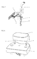
Figure 1 shows a typical extraoralradiographic apparatus 1 of the known art, comprising anX-ray source 7 projecting a collimated bundle of X-rays through a (not shown) patient; abi-dimensional X-ray sensor 8 positioned so as to measure the intensity of X-rays after they crossed the patient; adevice 5 for the positioning of the patient interposed between X-ray source and sensor; a C-arm 6 on whose ends saidX-ray source 7 andsensor 8 are supported; a mechanical system allowing the rotation and the translation of said C-arm around the patient, in order to acquire radiographic images from various positions; (not shown) electronic circuits such as to adjust and synchronize the working of the various parts of the apparatus. The position of the C-arm 6 can be adjusted to patient's height thanks to column 4 sliding oncolumns 3 fixed to the ground throughbase 2. Theextraoral apparatus 1 may further comprise anarm 11 for teleradiography, to which a further patient'spositioning device 13 is fixed, and ateleradiography sensor 15 is removably fixed onsupport 12. - The
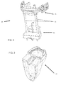
craniostat 20 of the present invention is shown inFigure 2 disconnected from theapparatus 1 for acquiring radiographs; when it is connected it is in the position indicated with 5 inFigure 1 . The craniostat is placed on itsspecific support 30, which is part of thepatient positioning device 5; thesupport 30 is shown inFigure 3 . -
Figure 4 shows the coupling between thelower portion 22 of thecraniostat 20 and thesupport 30 connecting it to theapparatus 1. The coupling craniostat-support is realized through fourpins longer pin 46 is the one ensuring the best coupling precision, thanks to minimal coupling tolerance in the respective hole, while the correct positioning and stability of the craniostat are ensured by the remaining shorter pins 45. The choice of different coupling tolerances is linked to production cost and to the ease of coupling by the human operator. A spring-loaded pressure plate acts on the pins, so as to inform the human operator that the perfect coupling craniostat-support has been reached, which ensures maximum stability. The spring is compressed when thepin 46 is inserted in its hole for its complete length, and its operation gives the operator an acoustic (metallic click) and tactile (friction of the vertical movement) feed-back. The spring-loaded pressure plate is indispensable on thelong pin 46 and optional on the threeshort pins 45. - For the sake of clarity, as shown in
Figure 2 thecraniostat 20 can be subdivided into anupper portion 21 and alower portion 22. A couple ofrods 23 connects the twoportions - In
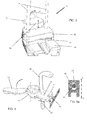
Figure 5 , the lower portion of thecraniostat 20 is shown resting onsupport 30 and complete withchin rest 52. Thelower portion 22 of the craniostat has a fixedbase 41, provided with alever 54 for blockingbite 53. Thechin rest 52, and thebite 54 are removable according to the needs of the different acquisitions. - The distance d between
bite 54 in its blocked position androds 23, indicated with a dotted line, is the widest possible so asrods 23 are out from the focal trough, but inside the anti-collision cylinder. In the preferred embodiment, said distance d is 55 mm. - When the
lever 53 is its unblocked position (in one of its two extreme positions, e.g. totally on the left), thebite 54 is free to vertically slide in the direction indicated by the linear double arrow, and to pivot in the direction indicated by the arched double arrow. This disposition is particularly comfortable when positioning a patient, in that the human operator firstly unblocks thebite 54 through thelever 53 and rotates it toward one of the tworods 23, rests patient's chin onchin rest 52, and then positions thebite 54 inside patient's oral cavity vertically adjusting it. When the operator blocks the position of thebite 54 throughlever 53, e.g. bringing the lever totally on the right, thebite 54 is automatically positioned in its correct sagittal position, thanks to its particular shape. -
Figure 6 shows the mechanism, contained in thebase 41, for blocking thebite 54. When thelever 53 is in its unblocked position, thestem 61 is in the portion having a circular section of thehole 63 ofblock 62, and is therefore free to move. When thelever 53 is in its blocked position, theblock 62 is pushed by acam 65 so as to compressspring 64 in the direction of the arrow. The portion of thehole 63 having a triangular section is coupled to thestem 61, blocking it through friction. Thestem 61 has in its turn a triangular transversal section, which allows both a higher friction, and an auto-centring on the sagittal plane. The axis A-A' shows the plane of the section shown inFigure 6a and allows to better appreciate the functioning of the block. Thehole 63 has a section partly rounded and partly triangular, and thestem 61 has a triangular section which, when blocked, is coupled to the triangular portion ofhole 63. When thelever 53 is brought in the unblocked position again, thecam 65 is rotated and thespring 64 pushes in a direction contrary to the arrow theblock 62, freeing the coupling between the triangular section ofhole 63 and ofstem 61 ofbite 54. - As can be seen from the Figures, triangular section means that a part of the delimitation surfaces of the hole, at least for a certain axial length of the bite itself, have two walls which are opposed and converging. These walls are preferably symmetrically positioned with respect to a plane containing the longitudinal axis and a diameter of
hole 63, such diameter coincides with a bisector of the angle defined by the two opposed converging walls. - The remaining part of the perimetral delimitation surface of
hole 63 can have any shape, and in this embodiment is cylindrical, i.e. having circular section; the wedge-shaped portion and the cylindrical portion are seamlessly joined together. - The
stem 61 has at least for a part of its axial, longitudinal extension a section substantially analogous to the section ofhole 63, but dimensionally smaller and such that saidstem 61 can slide both axially, in order to adjust the bite height with respect to the chin rest, and radially, i.e. in the direction of wedging a portion of the surface of the stem itself. The stem has two opposed and converging walls like a wedge, preferably with the same angle of the converging walls ofhole 63, also in the opposed direction of said walls, moving from the converging walls ofhole 63. - The tightening means, i.e. the mechanism controlled by the lever, thrust the stem in the wedging direction of the wedge-shaped portion of said stem into the wedge-shaped portion of the
hole 63, blocking said stem both in the axial direction and in its rotation around its own longitudinal axis. At the same time, while in the not tightened condition of thestem 61 in thehole 63 thestem 61 is free both to axially slide and also to rotate around its own axis, in the above-described tightened condition, not only the stem is blocked as regards its rotation, but thanks to the substantially wedge-shaped shape of thestem 61 and ofhole 63, said stem and therefore the wedge-shaped section of the bite are forced in the desired centring position, defined by the shapes and orientation of the wedge-shaped surfaces of bothhole 63 anstem 61. - The general concept expressed by the described forms of the present embodiment consists therefore in the fact that both the
stem 61 and itshousing hole 63 have both complementary surfaces of contact having a pre-defined angular orientation and a shape so as in tightening conditions ofstem 61 in the hole 63: said surfaces come into contact and define a pre-defined angular orientation of the stem around its own axis. -
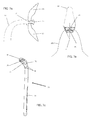
Figure 7 shows a further detail ofbite 54, which is particularly useful when acquiring bite-wing radiographies, which requires the positioning of the patient at a pre-defined height. To this aim, thestem 61 ofbite 54 has a particular profile of its transversal section. The upper part has a substantially circular section, while about halfway its lower section becomes triangular or wedge-shaped, for the reasons explained above linked to bite auto-centring. Moreover, at a pre-defined height, thestem 61 has ahorizontal recess 71. Insidebase 41 there is also asmall lever 72 pre-loaded by aspring 73, which constantly frictions, in a virtually undetectable way, against thestem 61. When therecess 71 is brought in correspondence of thesmall lever 72, there is an acoustic and tactile feed-back for the operator, who is informed of the precise reaching of the position for bite-wing acquisitions. The block of thebite 54, also for bite-wing positions, occurs through thelever 53. -
Figure 7a shows the sagittal section ofbite 54 which is kept between patient's teeth, whileFigure 7b shows a top view of thebite 54 end. The portion that the patient bites with her/his incisors is small. In theFigure 7a theanterior part 74 of the portion is shown, which has a net, not blunted angle, so as to ensure the stop of upper 101 andlower incisors 102, which thus lie on the same plane; in this way a panoramic image results with an as correct as possible focusing. On the other hand, theposterior part 75 is tapered and rounded to better fit patient's anatomy (Welander curve 103) and to reduce the thickness of the material crossed by X-rays. This tapering, indicated with angle α inFigure 7b , must nonetheless ensure a resting position sufficient for anterior teeth. In the preferred embodiment said angle α is comprised between 15 and 25 degrees. - Concerning the
bite 54, it was optimized to the aim of not appearing in the radiographies, yielding an artefact. Therefore, it was built using a radiolucent plastic material. Moreover, its profile has a particular shape which allows to minimize the quantity of plastic material. As can be seen inFigure 7c , in the lower side of thearched part 76 of the bite there is arecess 77 which reduces the thickness of the bite. With the aim of maintaining its rigidity, in thebite 54 there are tworibs 78 distinct in the bite distal part, which unite in the proximal part; on said ribs the stress transmitted by the patient is discharged. - In
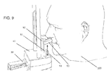
Figure 8 the coupling betweenchin rest 52 andbase 41 is shown. The coupling occurs through twopins pin 81 is inserted in a hole which has a reduced coupling tolerance. The fact that the coupling ofpin 82 is looser allows the operator to easily insert it into its hole, while the precise coupling ofpin 81 ensures the stability of the assembly. The weight of patient's head is sufficient to ensure the desired immobility, and therefore there is no spring-loaded pressure plate or similar devices. The presence ofchin rest 52 is required in practically all acquisitions, but those of temporomandibular joints, during which chin rest 52 must be removed. - In general terms, when chin rest 52 is removed, it is replaced by nose support 90, on which the patient rests her/his anterior nasal spine as shown in
Figure 9 . The nose support 90 is inserted through twopins chin rest 52 are inserted, with the same tolerances discussed above. Whenpatient 100 rests on nose support 90, arecess 93, on thecraniostat 20base 41, allows her/him to easily open and close her/his mouth, without the need of re-positioning the patient. - In the immediately following paragraphs the upper portion of the craniostat will be described in detail. The upper portion of the craniostat has to keep the patient in the desired position, and the most suitable points to this aim are considered patient's forehead (on the sagittal plane), the lateral parts of the cranium (laterally), the terminal part of the parietal bone (posteriorly).
- In
Figure 10 theupper portion 21 of the craniostat is shown, comprising aforehead rest 105 and two mobile rests 107 for the lateral portions of cranium. Theupper portion 21 is height adjustable onrods 23. In particular, theupper portion 21 comprises acrossbeam 104, having holes which allow to slide onrods 23. Oncrossbeam 104 there is a hole in which theforehead rest 105 is slidingly inserted. - Also on the
crossbeam 104 there are connected twosmall arms 106, which can pivot independently of one another, so as to adjust to the width of patient's cranium, accommodating also patients having remarkable dissymmetry. At the end of the twoarms 106 there are twosmall arches 107, free to independently pivot around their insertion fulcrum. Both thearms 106 and thesmall arches 107 have their fulcrum so as to rotate around axes substantially parallel to a vertical or longitudinal axis of patient's head. - At the two ends of each arch 107 there are two, optionally removable, rubber tips or
pads 108, which rest on patient's skin. Moreover, at the end of eacharm 106 there is aslot 109 which allows to insert an optional (not shown) band, generally in a soft, bendable material, which surrounds the posterior part of patient's head, so as to further immobilize her/him. The use of the band is optional and left to the preference of the individual human operator. - In
Figure 11 a detail of theforehead rest 105, sliding inside the (not shown)crossbeam 104 is shown. Theforehead rest 105 has a particular arched profile, and ends in awide rest surface 111, on which a small, optionally removable, cushion is fixed, made of a soft material (silicone, gum, foam) to improve patient's comfort. The profile ofrest surface 111 is slightly arched in order to better fit patient's anatomy. - Inside the
crossbeam 104, which was removed fromFigure 11 for the sake of clarity, there is an end-of-stroke device. Theforehead rest 105 is free to slide inside thecrossbeam 104, with two, one upper and one lower, limits. The lower limit is due to the fact thatrest 111 is larger than the seat inside which forehead rest 105 slides. The upper limit is due to the end-of-stroke device 112, which is provided with twosmall teeth 113 which perform a slight constant friction on theforehead rest 105. The joint betweenteeth 113 and recesses 114 in the upper end offorehead rest 105 prevents the accidental extraction of theforehead rest 105. Nonetheless, all the assembly is designed so that an intentional pressure allows the extraction of theforehead rest 105 from its seat in thecrossbeam 104 for cleaning, replacement, etc. Optional intermediate recesses can correspond to pre-defined positions of theforehead rest 105 if needed for particular acquisitions. -
Figure 12 shows a sagittal section of theforehead rest 105 inserted in its seat in thecrossbeam 104. It shows the working mechanism of theforehead rest 105. The working mechanism is highlighted inFigure 12 through the bold and dotted arrows. Basically, when the patient rests her/his forehead on therest surface 111, she/he applies a given pressure, represented by bold arrow c. The vector of the force has two components, shown by a and b arrows, in the two points A and B, thus blocking the sliding of theforehead rest 105 due to friction. On the other hand, when the fingers of the human operator act on points E and/or F, applying the pressures e and f, these have the two components represented by arrows a' and b', also in the points A and B. Therefore, the sliding of theforehead rest 105 is allowed inside its seat in thecrossbeam 104. The profile of theforehead rest 105 is studied so that the mechanisms of blocking and sliding can work in any position saidrest 105 can take while sliding inside its seat. - On the
forehead rest 105 there are two recesses in the points E and F so as to precisely indicate to the human operator where to apply pressure when she/he wishes to height adjust the position of theforehead rest 105. It is apparent from the profile of theforehead rest 105 that its height adjustment occurs in the direction of thickness, too. -
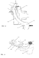
Figure 13 shows a detail of the blocking mechanism ofarm 106, inside which there is inserted a ferrule orscrew nut 134 leading theblock screw 133. The arms 106 (not shown in this Figure) have their fulcrum on apivot 131, and this allows to adjust them according to the width of patient's cranium, width exhibiting a wide variability. When the blocking mechanism is activated, theblock screw 133 enters into contact withblock 132, integral withcrossbeam 104, generating the friction needed for blocking the system. Theblock screw 133 is rotationally inserted in theferrule 134, which is connected with thelever 135, protruding from the structure itself in order to be used by the human operator as controls through rotation offerrule 134. The rotation of the ferrule, thanks to the thread and the fact that it is essentially stationary, entails an axial movement of the screw. - The
lever 135 can rotate between two extreme positions, the first of which is shown inFigure 10 (upwards) and the second of which is shown inFigure 15b (outwards). When thelever 135 is in the upward position as shown inFigure 10 , thearm 106 is free to rotate around itspivot 131 without friction. On the other hand, when thelever 135 is rotate downwardly, it will block, meetingblock 132, in any position comprised between the two extreme positions, position which is proportional to the width of patient's cranium. - The human operator, after accommodating the patient inside the
craniostat 20, adjusts the position of thearms 106 according to patient's anatomy, and then rotates thelevers 135 downwardly. -
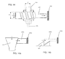
Figure 14 shows in detail the working of the block mechanism ofarms 106. The Figure shows a section along the rotation axis of the system ferrule 134-screw 133. The distance between theblock screw 133 and theblock 132 varies proportionally to patient's anatomy. When the patient's cranium is small, and the distance screw 133-block 132 is therefore great, to reach the block a turn of thescrew 133 will be needed which is wider than the turn of the screw needed with a big cranium, and this is ensured by the length of the thread ofscrew 133. When theblock screw 133, pushed by the rotation of the ferrule, comes into contact withblock 132, between the coupled faces of theferrule 134 and of thescrew thread 133 friction is generated, which blocks thearm 106. The block works only in the direction of opening thearms 106, because in the direction of closing there is patient's head. - The section of the
thread 141 is substantially a scalene trapezoid wherein the angles of the oblique surfaces working with the ferrule are different. The chosen angles, the lead p and the number of starts of the thread, and the diameter m of thescrew 133, all cooperate to create a fluid movement when the human operator operates thelever 135; on the other hand, when thelever 135 is in the block position, proportional to patient's anatomy, its friction is sufficient to block the patient. -
Figure 14 shows the preferred embodiment, based on a surface coupling system which blocks the moving parts by friction. However, based on the same principle there are many other possible embodiments, some of which are e.g. shown inFigures 14a and 14b . -
Figure 14a shows a wedge device, wherein the movement of therigid block 133a, conceptually equivalent to screw 133, is blocked by awedge 142. According to the distancerigid block 133a-block 132a, thewedge 142 will be lowered of a variable quantity, proportional to patient's anatomy. - On the other hand,
Figure 14b shows a saw tooth device, wherein the movement of therigid block 133b, conceptually equivalent to screw 133, is blocked by aspecular saw tooth 143. The disadvantage of this configuration is that it works only discontinuously, and does not allow a continuous adjustment. -
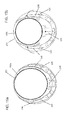
Figures 15a and 15b show the horizontal section of a cranium of a very big patient 100a and of a very small patient 100b, respectively. The comparison between the two Figures allows to appreciate the different position offorehead rest 105 and ofarms 106. In particular, inFigure 15a ,forehead rest 105 is positioned upwardly, and thanks to its arched profile, protrudes little with respect tocrossbeam 104. Thearms 106 are in their maximal outward extension, and therefore thelevers 135 are very near to their upward unblock position. Vice versa, inFigure 15a ,forehead rest 105 is positioned downwardly in its end-of-stroke position, and protrudes markedly towards patient's forehead, while thearms 106 are in their inward maximal extension, and therefore thelevers 135 are in their extreme block position, protruding outwardly. - In both
Figures 15a and 15b the section of the anti-collision cylinder is represented by the dottedcircumference 151. This allows to appreciate that, in the two extreme positions, even with a very big patient, the assembly patient-craniostat remains inside said cylinder. In particular, the space occupied by thelevers 135, whose position is proportional to patient's anatomy, is the same as the space freed through the closing of thearms 106 consequent to the inferior cranial diameter. In this way the assembly patient-craniostat remains always inside theanti-collision cylinder 151. - As already explained, the positioning needs are different for each acquisition (panoramic images; temporomandibular joints images; bite-wing images; three-dimensional images). In the following the method for patient positioning in the case of a panoramic acquisition is explained, which is probably the most articulate and common case. The human operator performs the following steps:
- According to the image to be acquired, the human operator fixes the
craniostat 20 on itssupport 30 in theradiographic apparatus 1; once it is positioned, she/he places the removable accessories (bite 54, chin rest 52); she/he positions thelever 53 in its unblocking position; she/he lifts theforehead rest 105; she/he completely opens thearms 106; she/he covers thebite 54 with a disposable protection and inserts it inside thehole 63 rotated toward one of therods 23; - The operator accommodates the
patient 100 inside theapparatus 1; the patient is asked to grabhandles 9; - Firstly the operator adjusts the
lower part 22 of thecraniostat 20; the patient is asked to rest her/his chin onchin rest 52; the operator adjusts the height of the sliding column 4 to give the suitable inclination to patient's head; - The patient is asked to open her/his mouth and the
bite 54 is rotated and lowered until theanterior part 74 is in contact with her/his lower incisors (102); - The patient is asked to bite the
bite 54 placing her/his incisors against theanterior part 74; - The operator blocks the
bite 54 position using thelever 53; the block of the patient in the correct position is particularly easy for the operator, who needs to move the lever only, and for the patient, who is not obliged to squeeze in anapparatus 1 where the position of the bite is already fixed; - Successively the operator adjusts the
upper part 21 of thecraniostat 20; the operator adjusts the height of thecrossbeam 104 sliding it on therods 23; the operator lowers theforehead rest 105 so as to contact patient's head; optionally the operator fixes an elastic band inside theslots 109 and blocks the posterior part of patient's head, too; - The operator adjusts the opening of the
arms 106 so thatarches 107 are in contact with the sides of patient's cranium; once found the contact, she/he moves thelevers 135 so as to block thearms 106 in a position which is comfortable for the patient. - Now the operator moves away from the
apparatus 1 and X-ray emission can start. - 1
- extraoral apparatus
- 2
- base
- 3
- fixed column
- 4
- sliding column
- 5
- patient positioning
- 6
- C-arm
- 7
- X-ray generator
- 8
- X-ray sensor
- 9
- handles
- 11
- teleradiography arm
- 12
- teleradiography sensor support
- 13
- teleradiography patient positioning
- 15
- teleradioragraphy X-ray sensor
- 20
- craniostat
- 21
- craniostat upper portion
- 22
- craniostat lower portion
- 23
- rods
- 30
- craniostat support
- 41
- craniostat base
- 45
- short pins
- 46
- long pin
- 52
- chin rest
- 53
- lever
- 54
- bite
- 61
- bite stem
- 62
- block
- 63
- hole
- 64
- spring
- 71
- bitewing recess
- 72
- small lever
- 73
- spring
- 74
- anterior part
- 75
- posterior part
- 76
- arched part
- 77
- recess on arched part
- 78
- ribs
- 81
- precise pin
- 82
- loose pin
- 90
- nose support
- 91
- precise pin
- 92
- loose pin
- 93
- recess
- 100
- patient
- 100a
- big patient
- 100b
- small patient
- 101
- upper incisors
- 102
- lower incisors
- 103
- Welander curve
- 104
- crossbeam
- 105
- forehead rest
- 106
- arm
- 107
- arch
- 108
- rubber tips
- 109
- band slot
- 111
- forehead rest surface
- 112
- end-of stroke device
- 113
- teeth
- 114
- recess
- 131
- pivot
- 132
- block
- 133
- block screw
- 133a
- rigid block
- 133b
- rigid block
- 134
- ferrule or screw nut
- 135
- lever
- 141
- thread profile
- 142
- wedge
- 143
- saw tooth
- 151
- anti-collision cylinder
Claims (11)
- Craniostat (20) for an extraoral dental radiographic apparatus (1), comprising a fixed base (41) in the lower portion of the craniostat, said base being provided with a lever, a chin rest (52), a bite block, both of which are preferably suitable for being removed from a support of a patient positioning device,
tightening means for blocking the bite(54), said tightening means comprising a lever (53), a block (62) having a hole (63) for housing a stem (61) of the bite (54), said block (62) defining a plane,
wherein said stem (61) comprising a lower portion having a transversal triangular or wedge-shaped section which defines centring surfaces having pre-defined orientation with respect to its own longitudinal axis, the bite (54) being adapted thereby to be blocked in a blocking position through the tightening of said centring surfaces against tightening surfaces of said hole (63), said hole (63) also having a pre-defined orientation defining a bite-centring position, so that in a tightened condition the bite (54) is automatically brought into the centring position on the plane of the block (62). - Craniostat (20) according to claim 1, wherein the tightening surfaces of the said hole (63) forms a portion of the said hole (3) having a wedge like or a triangular-like cross section at the said tightening surfaces the said centring surfaces of the stem (61) determining the said a triangular or wedge-shaped cross section of stem (61), cooperating with the said tightening surfaces of the hole (63) having a wedge like or a triangular-like cross section
- Craniostat (20) according to claim 1 or 2, wherein the terminal portion of the bite (54) exhibits:- An anterior part (74), having a net, not blunted angle, so as to ensure the stop of upper incisors (101) and lower incisors (102), which thus lie on the same plane;- A posterior part (75) which is tapered and rounded to better suit patient's anatomy (Welander's curve (103)) and to reduce the thickness of the material crossed by X-rays.
- Craniostat (20) according to one or more of the preceding claims, wherein the bite (54) is made of radiolucent plastic material, comprising a recess (77) reducing the thickness of the bite and two ribs (78) which are distinct in the distal part of the bite, which unite in its proximal part; on said ribs the stress transmitted by the patient is discharged.
- Craniostat (20) according to one or more of the preceding claims, wherein the bite (54) exhibits a recess (71) providing feed-back to a human operator for the exact positioning of the bite (54) for the acquisition of bite-wing radiographies.
- Craniostat (20) according to one or more of the preceding claims, wherein the craniostat (20) itself is removable from its support (30) and/or the chin rest (52) is removable from the lower portion (22) of the craniostat (20); the coupling of the craniostat (20) with the base (30) and/or between the lower portion (22) of the craniostat and the chin rest (52) occurs through the presence of at least two pins (45, 46; 81, 82); one of said pins (46, 81) has a coupling tolerance lower and/or a longer length with respect to the other pin/s (45, 82).
- Method for positioning a patient in an extraoral dental radiographic apparatus (1) comprising a craniostat according to claim 1 the said method comprising the following steps:- A human operator accommodates a patient (100) inside said apparatus (1);- Firstly said human operator adjusts the lower portion (22) of the craniostat (20);- asks the patient to rest her/his chin on the chin rest (52);- adjusts the height of the sliding column (4) to suitably incline patient's head;- asks the patient to open her/his mouth;- rotating and lowering the bite (54) until the anterior part (74) of the bite (54) is in contact with her/his lower incisors (102);- The operator asking the patient to bite the bite (54) stopping her/his incisors on the anterior part (74);
characterized in that
the operator vertically and sagittally blocks the position of the bite (54) using a lever (53) of said craniostat. - Method for positioning a patient in an extraoral dental radiographic apparatus (1) for acquiring a bite-wing radiography according to claim 7, further comprising the steps of blocking of the bite (54) at a pre-defined height thanks to the feed-back provided through the presence of a horizontal recess (71).
- Craniostat (20) for an extraoral dental radiographic apparatus (1), comprising a fixed base (41) in the lower portion of the craniostat, said base being provided with a lever, a chin rest (52), a bite (54), both of which are preferably suitable for being removed from a support of a patient positioning device, characterized in that a terminal portion of the bite (54) exhibits:- An anterior part (74), having a net, not blunted angle, so as to ensure the stop of upper incisors (101) and lower incisors (102), which thus lie on the same plane;- A posterior part (75) which is tapered and rounded to better suit patient's anatomy (Welander's curve (103)) and to reduce the thickness of the material crossed by X-rays.
- Craniostat (20) for an extraoral dental radiographic apparatus (1), comprising a fixed base (41) in the lower portion of the craniostat, said base being provided with a lever, a chin rest (52), a bite block, both of which are preferably suitable for being removed from a support of a patient positioning device, wherein the craniostat (20) itself is removable from its support (30) and/or the chin rest (52) is removable from the said base (41) of the craniostat (20); the coupling of the craniostat (20) with the base (30) and/or between the base (41) of the craniostat and the chin rest (52) occurs through the presence of at least two pins (45, 46; 81, 82); one of said pins (46, 81) has a coupling tolerance lower and/or a longer length with respect to the other pin/s (45, 82).
- Craniostat according to claims 9 or 10, characterised in that it is provided with the features of one or more of the preceding claims 1 to 6 and for carrying out a method according to claims 7 or 8.
Applications Claiming Priority (1)
| Application Number | Priority Date | Filing Date | Title |
|---|---|---|---|
| ITBO20140220 | 2014-04-17 |
Publications (3)
| Publication Number | Publication Date |
|---|---|
| EP2942014A2 true EP2942014A2 (en) | 2015-11-11 |
| EP2942014A3 EP2942014A3 (en) | 2016-03-02 |
| EP2942014B1 EP2942014B1 (en) | 2018-03-21 |
Family
ID=50897704
Family Applications (1)
| Application Number | Title | Priority Date | Filing Date |
|---|---|---|---|
| EP15163924.2A Active EP2942014B1 (en) | 2014-04-17 | 2015-04-16 | Craniostat for acquiring extraoral dental radiographies |
Country Status (4)
| Country | Link |
|---|---|
| US (1) | US9439609B2 (en) |
| EP (1) | EP2942014B1 (en) |
| KR (1) | KR101813472B1 (en) |
| CN (1) | CN104997530B (en) |
Cited By (1)
| Publication number | Priority date | Publication date | Assignee | Title |
|---|---|---|---|---|
| ITUA20162728A1 (en) * | 2016-04-20 | 2017-10-20 | Cefla Soc Cooperativa | cephalostat |
Families Citing this family (5)
| Publication number | Priority date | Publication date | Assignee | Title |
|---|---|---|---|---|
| USD810304S1 (en) * | 2014-04-24 | 2018-02-13 | Cefla Societá Cooperativa | Head support |
| WO2016135526A1 (en) * | 2015-02-27 | 2016-09-01 | Trophy | Bite block for cbct imaging device |
| FI127695B (en) * | 2017-03-17 | 2018-12-14 | Planmeca Oy | X-ray apparatus and patient support arrangement |
| CN109480895B (en) * | 2018-11-29 | 2024-05-21 | 枣庄市立医院 | Medical imaging plain X-ray shooting body position auxiliary device |
| CN113967031B (en) * | 2021-10-29 | 2024-03-01 | 陈勇 | Head fixing device for CT (computed tomography) examination of skull |
Citations (2)
| Publication number | Priority date | Publication date | Assignee | Title |
|---|---|---|---|---|
| US3936641A (en) | 1974-10-21 | 1976-02-03 | Pennwalt Corporation | Head immobilizing device for panoramic x-ray apparatus |
| WO2013014488A1 (en) | 2011-07-22 | 2013-01-31 | Trophy | Shield for patient positioning in extra-oral imaging |
Family Cites Families (13)
| Publication number | Priority date | Publication date | Assignee | Title |
|---|---|---|---|---|
| FI92973C (en) * | 1991-05-06 | 1995-02-10 | Planmeca Oy | Procedure and apparatus for panoramic X-ray photography |
| CN2376267Y (en) * | 1999-06-04 | 2000-05-03 | 威海市文登中心医院 | Curved surface X-ray machine jaw device |
| DE102004041440A1 (en) * | 2004-08-27 | 2006-03-02 | Dürr Dental GmbH & Co. KG | Method for determining the desired relative position of a patient in a dental panoramic X-ray device or the target path on which this is moved with respect to a patient and a device suitable for this purpose |
| US7195395B2 (en) * | 2005-02-28 | 2007-03-27 | Kerrhawe Sa | Dental sensor clamp |
| US20060227939A1 (en) * | 2005-04-11 | 2006-10-12 | Gendex Corporation | Bite piece for a dental x-ray system |
| DE102006021639A1 (en) * | 2006-05-08 | 2007-11-15 | Sirona Dental Systems Gmbh | Dental X-ray apparatus comprising a patient positioning on a support part with a forehead support |
| US9113799B2 (en) * | 2009-07-30 | 2015-08-25 | Telesystems Co., Ltd. | Radiation imaging apparatus and imaging method using radiation |
| FI126561B (en) * | 2010-02-23 | 2017-02-15 | Planmeca Oy | Patient support for dental x-ray equipment |
| CN201719264U (en) * | 2010-06-11 | 2011-01-26 | 天津医药集团众健康达医疗器械有限公司 | Panoramic X-ray machine jaw support |
| CN203524692U (en) * | 2013-07-01 | 2014-04-09 | 四川九九天目医疗器械有限公司 | A lower jaw fixing device for oral cavity computed tomography |
| CN203388877U (en) * | 2013-07-19 | 2014-01-15 | 薛永福 | Panoramic tooth photography positioner for radiology department |
| KR101796350B1 (en) * | 2014-04-17 | 2017-11-09 | 쎄플라 쏘씨에타 쿠퍼라티바 | Craniostat for acquiring extraoral dental radiographies |
| KR101838349B1 (en) * | 2014-04-17 | 2018-03-13 | 쎄플라 쏘씨에타 쿠퍼라티바 | Craniostat for acquiring extraoral dental radiographies |
-
2015
- 2015-04-10 KR KR1020150050836A patent/KR101813472B1/en active IP Right Grant
- 2015-04-15 US US14/687,027 patent/US9439609B2/en active Active
- 2015-04-16 EP EP15163924.2A patent/EP2942014B1/en active Active
- 2015-04-17 CN CN201510184617.8A patent/CN104997530B/en active Active
Patent Citations (2)
| Publication number | Priority date | Publication date | Assignee | Title |
|---|---|---|---|---|
| US3936641A (en) | 1974-10-21 | 1976-02-03 | Pennwalt Corporation | Head immobilizing device for panoramic x-ray apparatus |
| WO2013014488A1 (en) | 2011-07-22 | 2013-01-31 | Trophy | Shield for patient positioning in extra-oral imaging |
Cited By (3)
| Publication number | Priority date | Publication date | Assignee | Title |
|---|---|---|---|---|
| ITUA20162728A1 (en) * | 2016-04-20 | 2017-10-20 | Cefla Soc Cooperativa | cephalostat |
| EP3235436A1 (en) * | 2016-04-20 | 2017-10-25 | Cefla Societa' Cooperativa | Cephalostat |
| US10441227B2 (en) | 2016-04-20 | 2019-10-15 | Cefla Societá Cooperativa | Cephalostat |
Also Published As
| Publication number | Publication date |
|---|---|
| CN104997530B (en) | 2019-08-20 |
| KR101813472B1 (en) | 2017-12-29 |
| US20150297154A1 (en) | 2015-10-22 |
| US9439609B2 (en) | 2016-09-13 |
| KR20150120295A (en) | 2015-10-27 |
| EP2942014B1 (en) | 2018-03-21 |
| CN104997530A (en) | 2015-10-28 |
| EP2942014A3 (en) | 2016-03-02 |
Similar Documents
| Publication | Publication Date | Title |
|---|---|---|
| EP2932904B1 (en) | Craniostat for acquiring extraoral dental radiographies | |
| EP2942014B1 (en) | Craniostat for acquiring extraoral dental radiographies | |
| EP2932903B1 (en) | Craniostat for acquiring extraoral dental radiographies | |
| KR20170012244A (en) | Orthodontic apparatus and method for producing an orthodontic apparatus | |
| EP3746014B1 (en) | Sleep apnea oral appliance with connectors | |
| US11701071B2 (en) | Dental bite block for 2D imaging | |
| KR102095273B1 (en) | Impressing tray and denture manufacturing process using the impressing tray and ct imaging apparatus | |
| EP3235436B1 (en) | Cephalostat | |
| JP3615733B2 (en) | Auxiliary tool for intraoral radiography | |
| US4144460A (en) | Method and device for radiographing human jaw joints | |
| JP6069678B2 (en) | Alignment tool for X-ray imaging apparatus and X-ray imaging apparatus having the same | |
| JPH0446577B2 (en) | ||
| RU2803060C1 (en) | Positioner for intraoral digital dental radiography | |
| Carver | Orthopantomography and cephalometry | |
| WO1980001961A1 (en) | Method and device for radiographing human jaw joints | |
| CN110573082A (en) | X-ray imaging apparatus and patient support | |
| CN110573081A (en) | X-ray imaging apparatus and patient support device |
Legal Events
| Date | Code | Title | Description |
|---|---|---|---|
| PUAI | Public reference made under article 153(3) epc to a published international application that has entered the european phase |
Free format text: ORIGINAL CODE: 0009012 |
|
| AK | Designated contracting states |
Kind code of ref document: A2 Designated state(s): AL AT BE BG CH CY CZ DE DK EE ES FI FR GB GR HR HU IE IS IT LI LT LU LV MC MK MT NL NO PL PT RO RS SE SI SK SM TR |
|
| AX | Request for extension of the european patent |
Extension state: BA ME |
|
| PUAL | Search report despatched |
Free format text: ORIGINAL CODE: 0009013 |
|
| RIC1 | Information provided on ipc code assigned before grant |
Ipc: A61B 6/00 20060101ALI20160120BHEP Ipc: F16B 2/18 20060101ALI20160120BHEP Ipc: A61B 6/04 20060101AFI20160120BHEP Ipc: A61B 6/14 20060101ALI20160120BHEP |
|
| AK | Designated contracting states |
Kind code of ref document: A3 Designated state(s): AL AT BE BG CH CY CZ DE DK EE ES FI FR GB GR HR HU IE IS IT LI LT LU LV MC MK MT NL NO PL PT RO RS SE SI SK SM TR |
|
| AX | Request for extension of the european patent |
Extension state: BA ME |
|
| 17P | Request for examination filed |
Effective date: 20160829 |
|
| RBV | Designated contracting states (corrected) |
Designated state(s): AL AT BE BG CH CY CZ DE DK EE ES FI FR GB GR HR HU IE IS IT LI LT LU LV MC MK MT NL NO PL PT RO RS SE SI SK SM TR |
|
| GRAP | Despatch of communication of intention to grant a patent |
Free format text: ORIGINAL CODE: EPIDOSNIGR1 |
|
| INTG | Intention to grant announced |
Effective date: 20171030 |
|
| GRAS | Grant fee paid |
Free format text: ORIGINAL CODE: EPIDOSNIGR3 |
|
| GRAA | (expected) grant |
Free format text: ORIGINAL CODE: 0009210 |
|
| AK | Designated contracting states |
Kind code of ref document: B1 Designated state(s): AL AT BE BG CH CY CZ DE DK EE ES FI FR GB GR HR HU IE IS IT LI LT LU LV MC MK MT NL NO PL PT RO RS SE SI SK SM TR |
|
| REG | Reference to a national code |
Ref country code: GB Ref legal event code: FG4D |
|
| REG | Reference to a national code |
Ref country code: CH Ref legal event code: EP |
|
| REG | Reference to a national code |
Ref country code: AT Ref legal event code: REF Ref document number: 980221 Country of ref document: AT Kind code of ref document: T Effective date: 20180415 |
|
| REG | Reference to a national code |
Ref country code: IE Ref legal event code: FG4D |
|
| REG | Reference to a national code |
Ref country code: DE Ref legal event code: R096 Ref document number: 602015008969 Country of ref document: DE |
|
| REG | Reference to a national code |
Ref country code: FR Ref legal event code: PLFP Year of fee payment: 4 |
|
| REG | Reference to a national code |
Ref country code: NL Ref legal event code: MP Effective date: 20180321 |
|
| PG25 | Lapsed in a contracting state [announced via postgrant information from national office to epo] |
Ref country code: CY Free format text: LAPSE BECAUSE OF FAILURE TO SUBMIT A TRANSLATION OF THE DESCRIPTION OR TO PAY THE FEE WITHIN THE PRESCRIBED TIME-LIMIT Effective date: 20180321 Ref country code: LT Free format text: LAPSE BECAUSE OF FAILURE TO SUBMIT A TRANSLATION OF THE DESCRIPTION OR TO PAY THE FEE WITHIN THE PRESCRIBED TIME-LIMIT Effective date: 20180321 Ref country code: HR Free format text: LAPSE BECAUSE OF FAILURE TO SUBMIT A TRANSLATION OF THE DESCRIPTION OR TO PAY THE FEE WITHIN THE PRESCRIBED TIME-LIMIT Effective date: 20180321 Ref country code: NO Free format text: LAPSE BECAUSE OF FAILURE TO SUBMIT A TRANSLATION OF THE DESCRIPTION OR TO PAY THE FEE WITHIN THE PRESCRIBED TIME-LIMIT Effective date: 20180621 |
|
| REG | Reference to a national code |
Ref country code: LT Ref legal event code: MG4D |
|
| REG | Reference to a national code |
Ref country code: AT Ref legal event code: MK05 Ref document number: 980221 Country of ref document: AT Kind code of ref document: T Effective date: 20180321 |
|
| PG25 | Lapsed in a contracting state [announced via postgrant information from national office to epo] |
Ref country code: GR Free format text: LAPSE BECAUSE OF FAILURE TO SUBMIT A TRANSLATION OF THE DESCRIPTION OR TO PAY THE FEE WITHIN THE PRESCRIBED TIME-LIMIT Effective date: 20180622 Ref country code: RS Free format text: LAPSE BECAUSE OF FAILURE TO SUBMIT A TRANSLATION OF THE DESCRIPTION OR TO PAY THE FEE WITHIN THE PRESCRIBED TIME-LIMIT Effective date: 20180321 Ref country code: LV Free format text: LAPSE BECAUSE OF FAILURE TO SUBMIT A TRANSLATION OF THE DESCRIPTION OR TO PAY THE FEE WITHIN THE PRESCRIBED TIME-LIMIT Effective date: 20180321 Ref country code: SE Free format text: LAPSE BECAUSE OF FAILURE TO SUBMIT A TRANSLATION OF THE DESCRIPTION OR TO PAY THE FEE WITHIN THE PRESCRIBED TIME-LIMIT Effective date: 20180321 Ref country code: BG Free format text: LAPSE BECAUSE OF FAILURE TO SUBMIT A TRANSLATION OF THE DESCRIPTION OR TO PAY THE FEE WITHIN THE PRESCRIBED TIME-LIMIT Effective date: 20180621 |
|
| PG25 | Lapsed in a contracting state [announced via postgrant information from national office to epo] |
Ref country code: PL Free format text: LAPSE BECAUSE OF FAILURE TO SUBMIT A TRANSLATION OF THE DESCRIPTION OR TO PAY THE FEE WITHIN THE PRESCRIBED TIME-LIMIT Effective date: 20180321 Ref country code: AL Free format text: LAPSE BECAUSE OF FAILURE TO SUBMIT A TRANSLATION OF THE DESCRIPTION OR TO PAY THE FEE WITHIN THE PRESCRIBED TIME-LIMIT Effective date: 20180321 Ref country code: ES Free format text: LAPSE BECAUSE OF FAILURE TO SUBMIT A TRANSLATION OF THE DESCRIPTION OR TO PAY THE FEE WITHIN THE PRESCRIBED TIME-LIMIT Effective date: 20180321 Ref country code: EE Free format text: LAPSE BECAUSE OF FAILURE TO SUBMIT A TRANSLATION OF THE DESCRIPTION OR TO PAY THE FEE WITHIN THE PRESCRIBED TIME-LIMIT Effective date: 20180321 Ref country code: RO Free format text: LAPSE BECAUSE OF FAILURE TO SUBMIT A TRANSLATION OF THE DESCRIPTION OR TO PAY THE FEE WITHIN THE PRESCRIBED TIME-LIMIT Effective date: 20180321 Ref country code: NL Free format text: LAPSE BECAUSE OF FAILURE TO SUBMIT A TRANSLATION OF THE DESCRIPTION OR TO PAY THE FEE WITHIN THE PRESCRIBED TIME-LIMIT Effective date: 20180321 |
|
| PG25 | Lapsed in a contracting state [announced via postgrant information from national office to epo] |
Ref country code: AT Free format text: LAPSE BECAUSE OF FAILURE TO SUBMIT A TRANSLATION OF THE DESCRIPTION OR TO PAY THE FEE WITHIN THE PRESCRIBED TIME-LIMIT Effective date: 20180321 Ref country code: CZ Free format text: LAPSE BECAUSE OF FAILURE TO SUBMIT A TRANSLATION OF THE DESCRIPTION OR TO PAY THE FEE WITHIN THE PRESCRIBED TIME-LIMIT Effective date: 20180321 Ref country code: SK Free format text: LAPSE BECAUSE OF FAILURE TO SUBMIT A TRANSLATION OF THE DESCRIPTION OR TO PAY THE FEE WITHIN THE PRESCRIBED TIME-LIMIT Effective date: 20180321 Ref country code: SM Free format text: LAPSE BECAUSE OF FAILURE TO SUBMIT A TRANSLATION OF THE DESCRIPTION OR TO PAY THE FEE WITHIN THE PRESCRIBED TIME-LIMIT Effective date: 20180321 |
|
| REG | Reference to a national code |
Ref country code: CH Ref legal event code: PL |
|
| REG | Reference to a national code |
Ref country code: BE Ref legal event code: MM Effective date: 20180430 |
|
| PG25 | Lapsed in a contracting state [announced via postgrant information from national office to epo] |
Ref country code: PT Free format text: LAPSE BECAUSE OF FAILURE TO SUBMIT A TRANSLATION OF THE DESCRIPTION OR TO PAY THE FEE WITHIN THE PRESCRIBED TIME-LIMIT Effective date: 20180723 |
|
| REG | Reference to a national code |
Ref country code: DE Ref legal event code: R097 Ref document number: 602015008969 Country of ref document: DE |
|
| REG | Reference to a national code |
Ref country code: IE Ref legal event code: MM4A |
|
| PLBE | No opposition filed within time limit |
Free format text: ORIGINAL CODE: 0009261 |
|
| STAA | Information on the status of an ep patent application or granted ep patent |
Free format text: STATUS: NO OPPOSITION FILED WITHIN TIME LIMIT |
|
| PG25 | Lapsed in a contracting state [announced via postgrant information from national office to epo] |
Ref country code: DK Free format text: LAPSE BECAUSE OF FAILURE TO SUBMIT A TRANSLATION OF THE DESCRIPTION OR TO PAY THE FEE WITHIN THE PRESCRIBED TIME-LIMIT Effective date: 20180321 Ref country code: LU Free format text: LAPSE BECAUSE OF NON-PAYMENT OF DUE FEES Effective date: 20180416 Ref country code: MC Free format text: LAPSE BECAUSE OF FAILURE TO SUBMIT A TRANSLATION OF THE DESCRIPTION OR TO PAY THE FEE WITHIN THE PRESCRIBED TIME-LIMIT Effective date: 20180321 |
|
| 26N | No opposition filed |
Effective date: 20190102 |
|
| PG25 | Lapsed in a contracting state [announced via postgrant information from national office to epo] |
Ref country code: CH Free format text: LAPSE BECAUSE OF NON-PAYMENT OF DUE FEES Effective date: 20180430 Ref country code: BE Free format text: LAPSE BECAUSE OF NON-PAYMENT OF DUE FEES Effective date: 20180430 Ref country code: LI Free format text: LAPSE BECAUSE OF NON-PAYMENT OF DUE FEES Effective date: 20180430 |
|
| PG25 | Lapsed in a contracting state [announced via postgrant information from national office to epo] |
Ref country code: IE Free format text: LAPSE BECAUSE OF NON-PAYMENT OF DUE FEES Effective date: 20180416 |
|
| PG25 | Lapsed in a contracting state [announced via postgrant information from national office to epo] |
Ref country code: SI Free format text: LAPSE BECAUSE OF FAILURE TO SUBMIT A TRANSLATION OF THE DESCRIPTION OR TO PAY THE FEE WITHIN THE PRESCRIBED TIME-LIMIT Effective date: 20180321 |
|
| GBPC | Gb: european patent ceased through non-payment of renewal fee |
Effective date: 20190416 |
|
| PG25 | Lapsed in a contracting state [announced via postgrant information from national office to epo] |
Ref country code: GB Free format text: LAPSE BECAUSE OF NON-PAYMENT OF DUE FEES Effective date: 20190416 Ref country code: MT Free format text: LAPSE BECAUSE OF NON-PAYMENT OF DUE FEES Effective date: 20180416 |
|
| PG25 | Lapsed in a contracting state [announced via postgrant information from national office to epo] |
Ref country code: TR Free format text: LAPSE BECAUSE OF FAILURE TO SUBMIT A TRANSLATION OF THE DESCRIPTION OR TO PAY THE FEE WITHIN THE PRESCRIBED TIME-LIMIT Effective date: 20180321 |
|
| PG25 | Lapsed in a contracting state [announced via postgrant information from national office to epo] |
Ref country code: MK Free format text: LAPSE BECAUSE OF NON-PAYMENT OF DUE FEES Effective date: 20180321 Ref country code: HU Free format text: LAPSE BECAUSE OF FAILURE TO SUBMIT A TRANSLATION OF THE DESCRIPTION OR TO PAY THE FEE WITHIN THE PRESCRIBED TIME-LIMIT; INVALID AB INITIO Effective date: 20150416 |
|
| PG25 | Lapsed in a contracting state [announced via postgrant information from national office to epo] |
Ref country code: IS Free format text: LAPSE BECAUSE OF FAILURE TO SUBMIT A TRANSLATION OF THE DESCRIPTION OR TO PAY THE FEE WITHIN THE PRESCRIBED TIME-LIMIT Effective date: 20180721 |
|
| PGFP | Annual fee paid to national office [announced via postgrant information from national office to epo] |
Ref country code: FI Payment date: 20240320 Year of fee payment: 10 |
|
| PGFP | Annual fee paid to national office [announced via postgrant information from national office to epo] |
Ref country code: IT Payment date: 20240320 Year of fee payment: 10 Ref country code: FR Payment date: 20240320 Year of fee payment: 10 |
|
| PGFP | Annual fee paid to national office [announced via postgrant information from national office to epo] |
Ref country code: DE Payment date: 20240320 Year of fee payment: 10 |