EP2940834A2 - Motor - Google Patents
Motor Download PDFInfo
- Publication number
- EP2940834A2 EP2940834A2 EP15162457.4A EP15162457A EP2940834A2 EP 2940834 A2 EP2940834 A2 EP 2940834A2 EP 15162457 A EP15162457 A EP 15162457A EP 2940834 A2 EP2940834 A2 EP 2940834A2
- Authority
- EP
- European Patent Office
- Prior art keywords
- wire
- conducting
- winding
- wire portion
- connecting wire
- Prior art date
- Legal status (The legal status is an assumption and is not a legal conclusion. Google has not performed a legal analysis and makes no representation as to the accuracy of the status listed.)
- Granted
Links
Images




Classifications
-
- H—ELECTRICITY
- H02—GENERATION; CONVERSION OR DISTRIBUTION OF ELECTRIC POWER
- H02K—DYNAMO-ELECTRIC MACHINES
- H02K3/00—Details of windings
- H02K3/04—Windings characterised by the conductor shape, form or construction, e.g. with bar conductors
- H02K3/28—Layout of windings or of connections between windings
-
- H—ELECTRICITY
- H02—GENERATION; CONVERSION OR DISTRIBUTION OF ELECTRIC POWER
- H02K—DYNAMO-ELECTRIC MACHINES
- H02K3/00—Details of windings
- H02K3/04—Windings characterised by the conductor shape, form or construction, e.g. with bar conductors
- H02K3/18—Windings for salient poles
-
- H—ELECTRICITY
- H02—GENERATION; CONVERSION OR DISTRIBUTION OF ELECTRIC POWER
- H02K—DYNAMO-ELECTRIC MACHINES
- H02K3/00—Details of windings
- H02K3/32—Windings characterised by the shape, form or construction of the insulation
- H02K3/325—Windings characterised by the shape, form or construction of the insulation for windings on salient poles, such as claw-shaped poles
-
- H—ELECTRICITY
- H02—GENERATION; CONVERSION OR DISTRIBUTION OF ELECTRIC POWER
- H02K—DYNAMO-ELECTRIC MACHINES
- H02K3/00—Details of windings
- H02K3/32—Windings characterised by the shape, form or construction of the insulation
- H02K3/34—Windings characterised by the shape, form or construction of the insulation between conductors or between conductor and core, e.g. slot insulation
- H02K3/345—Windings characterised by the shape, form or construction of the insulation between conductors or between conductor and core, e.g. slot insulation between conductor and core, e.g. slot insulation
Definitions
- the present invention relates to a motor.
- each conducting wire forms a plurality of winding wire portions around teeth. Further, the plurality of winding wire portions are connected by connecting wires.
- the connecting wires are disposed so as to extend in a circumferential direction along the radially outer surface of an insulator. Further, an end portion of each conducting wire is led out from the winding wire portion and connected to a connection destination such as a bus bar.
- An object of the present invention is to provide a technique capable of reducing the radial dimension of a motor by devising a method of winding a conducting wire.
- the invention is based on the inventors' findings that in a case where a bus bar or the like which is a connection destination of a conducting wire is located on the upper side in an axial direction of a stator, it is necessary for an end portion of each conducting wire to be led out axially upward from a winding wire portion. If so, there is a case where a connecting wire of the conducting wire which is wound second or later and a lead-out wire of the previously wound conducting wire interfere with each other. In this case, the connecting wire of the conducting wire which is wound second or later and the lead-out wire of the previously wound conducting wire are disposed so as to radially overlap on the outside in the radial direction of a wall portion. As a result, the conducting wire partially protrudes radially outward, and thus there is a problem in which the radial dimension of the entire motor increases.
- a motor has a stator, and a rotor which is rotatably supported on the inside in a radial direction of the stator.
- the stator has a stator core which is a magnetic body, an insulator mounted on the stator core, and first, second, and third conducting wires which are wound around the insulator and through which electric currents of the respective phases of a three-phase alternating current flow.
- the stator core has a core back which is seamlessly connected in an annular shape around a central axis extending up and down, and a plurality of teeth extending radially inward from the core back.
- the insulator has a teeth insulating portion which is interposed between each of the teeth and the conducting wire, and a wall portion extending in a circumferential direction further on the outside in the radial direction and on the upper side than the teeth insulating portion.
- Each of the first, second, and third conducting wires includes a plurality of winding wire portions which are wound around the teeth insulating portion, one or more connecting wire portions performing relay between the plurality of winding wire portions, and a lead-out wire portion extending axially upward from the winding wire portion.
- the one or more connecting wire portions of the first conducting wire have only outer connecting wire portions passing through the outside in the radial direction of the wall portion.
- the one or more connecting wire portions of the second and third conducting wires have outer connecting wire portions passing through the outside in the radial direction of the wall portion, and inner connecting wire portions passing through the inside in the radial direction of the wall portion.
- the inner connecting wire portion of the second conducting wire passes through the inside in the radial direction of the lead-out wire portion of the first conducting wire
- the inner connecting wire portion of the third conducting wire passes through the inside in the radial direction of the lead-out wire portion of the first conducting wire and the lead-out wire portion of the second conducting wire.
- a motor according to an exemplary second invention of this application has a stator, and a rotor which is rotatably supported on the inside in a radial direction of the stator.
- the stator has a stator core which is a magnetic body, an insulator mounted on the stator core, and first, second, and third conducting wires which are wound around the insulator and through which electric currents of the respective phases of a three-phase alternating current flow.
- the stator core has a core back which is seamlessly connected in an annular shape around a central axis extending up and down, and a plurality of teeth extending radially inward from the core back.
- the insulator has a teeth insulating portion which is interposed between each of the teeth and the conducting wire, and a wall portion extending in a circumferential direction further on the outside in the radial direction and on the upper side than the teeth insulating portion.
- Each of the first, second, and third conducting wires includes a plurality of winding wire portions which are wound around the teeth insulating portion, one or more connecting wire portions performing relay between the plurality of winding wire portions, and a lead-out wire portion extending axially upward from the winding wire portion.
- the one or more connecting wire portions of at least one conducting wire have outer connecting wire portions passing through the outside in the radial direction of the wall portion, and inner connecting wire portions passing through the inside in the radial direction of the wall portion.
- the outer connecting wire portion and the inner connecting wire portion are continuous, and the at least one conducting wire crosses the wall portion at a boundary between the outer connecting wire portion and the inner connecting wire portion.
- the interference of the connecting wire portion with the lead-out wire portions of other conducting wires can be avoided.
- the connecting wire portion and the lead-out wire portion do not radially overlap further on the outside in the radial direction than the wall portion. In this way, it is possible to reduce the radial dimension of the motor.
- At least one conducting wire has the outer connecting wire portion and the inner connecting wire portion.
- a direction parallel to a central axis of a motor is referred to as an "axial direction”
- a direction orthogonal to the central axis of the motor is referred to as a "radial direction”
- a direction along an arc centered on the central axis of the motor is referred to as a "circumferential direction”.
- the shape or the positional relationship of each portion will be described with the axial direction set to be a vertical direction and the side of a lead-out wire portion with respect to a winding wire portion set to be the top.
- the definition of the vertical direction is not intended to limit a direction at the time of the manufacturing and the time of the use of a motor according to the present invention.
- a "direction parallel to” also includes a direction substantially parallel to.
- a "direction orthogonal to” also includes a direction substantially orthogonal to.
- Fig. 1 is a diagram when a motor 1A according to a first embodiment of the present invention is viewed from the upper side in the axial direction.
- the motor 1A has a stator 22A and a rotor 32A.
- the rotor 32A is rotatably supported on the inside in the radial direction of the stator 22A.
- the stator 22A has a stator core 51A which is a magnetic body, and an insulator 52A mounted on the stator core 51A.
- the stator core 51A has a core back 511 A and a plurality of teeth 512A.
- the core back 511A is seamlessly connected in an annular shape around a central axis 9A.
- the plurality of teeth 512A extend radially inward from the core back 511A.
- the insulator 52A has a teeth insulating portion 521 A and a wall portion 522A.
- the teeth insulating portion 521A is interposed between each of the teeth 512A and a winding wire portion 61A (described later).
- the wall portion 522A extends in the circumferential direction further on the outside in the radial direction and the on upper side than the teeth insulating portion 521A.
- a first conducting wire W1A, a second conducting wire W2A, and a third conducting wire W3A are wound around the insulator 52A. Electric currents of the respective phases of a three-phase alternating current respectively flow through the first conducting wire W1A, the second conducting wire W2A, and the third conducting wire W3A.
- Each of the conducting wires W1A, W2A, and W3A includes two winding wire portions 61A, a single connecting wire portion 62A, and two lead-out wire portions 63A.
- the winding wire portion 61A is wound around the teeth insulating portion 521A of the insulator 52A.
- the connecting wire portion 62A performs relay between the plurality of winding wire portions 61A.
- the lead-out wire portion 63A extends axially upward from the winding wire portion 61A of a winding start or a winding end.
- the connecting wire portion 62A of the first conducting wire W1A passes through further on the outside in the radial direction than the wall portion 522A of the insulator 52A. That is, the connecting wire portion 62A of the first conducting wire W1A has only an outer connecting wire portion 621A passing through the outside in the radial direction of the wall portion 522A.
- each of the connecting wire portions 62A of the second conducting wire W2A and the third conducting wire W3A has an outer connecting wire portion 621A passing through the outside in the radial direction of the wall portion 522A, and an inner connecting wire portion 622A passing through the inside in the radial direction of the wall portion 522A.
- the inner connecting wire portion 622A of the second conducting wire W2A passes through the inside in the radial direction of the lead-out wire portion 63A of a winding end of the first conducting wire W1A. For this reason, it is possible to avoid the lead-out wire portion 63A of the first conducting wire W1A and the connecting wire portion 62A of the second conducting wire W2A interfering with each other further on the outside in the radial direction than the wall portion 522A. That is, the lead-out wire portion 63A of the first conducting wire W1A and the connecting wire portion 62A of the second conducting wire W2A do not radially overlap further on the outside in the radial direction than the wall portion 522A.
- the third conducting wire W3A has two inner connecting wire portions 622A.
- the inner connecting wire portion 622A on one side of the third conducting wire W3A passes through the inside in the radial direction of the lead-out wire portion 63A of a winding end of the first conducting wire W1A.
- the inner connecting wire portion 622A on the other side of the third conducting wire W3A passes through the inside in the radial direction of the lead-out wire portion 63A of a winding end of the second conducting wire W2A.
- the connecting wire portion 62A of the third conducting wire W3A interfering with the lead-out wire portion 63A of the first conducting wire W1A and the connecting wire portion 63A of the second conducting wire W2A further on the outside in the radial direction than the wall portion 522A. That is, the lead-out wire portion 63A of the first conducting wire W1A and the lead-out wire portion 63A of the second conducting wire W2A do not radially overlap with the lead-out wire portion 62A of the third conducting wire W3A further on the outside in the radial direction than the wall portion 522A.
- the connecting wire portions 62A of the second conducting wire W2A and the third conducting wire W3A are disposed while avoiding interference with the lead-out wire portion 63A of the other conducting wire. In this way, radial overlap of the conducting wires further on the outside in the radial direction of the wall portion 522A is avoided. As a result, it is possible to reduce the radial dimension of the motor 1 A.
- the outer connecting wire portion 621A and the inner connecting wire portion 622A of the second conducting wire W2A are continuous with each other.
- the second conducting wire W2A crosses the wall portion 522A at the boundary between the inner connecting wire portion 622A and the outer connecting wire portion 621A.
- the pair of outer connecting wire portion 621A and inner connecting wire portion 622A of the third conducting wire W3A is continuous with each other.
- the third conducting wire W3A crosses the wall portion 522A at the boundary between the inner connecting wire portion 622A and the outer connecting wire portion 621A. In this manner, if the outer connecting wire portion 621A and the inner connecting wire portion 622A are provided continuously, it is possible to suppress the radially inward protrusion of the inner connecting wire portion 622A.
- Fig. 2 is a vertical cross-sectional view of a motor 1 according to the second embodiment.
- the motor 1 according to this embodiment is mounted on, for example, an automobile and used in order to generate the driving force of a power steering.
- the motor according to the present invention may be used for uses other than the power steering.
- the motor according to the present invention may be used as a drive source of the other site of an automobile, for example, a fan for engine cooling or an oil pump.
- the motor according to the present invention may also be mounted on home electric appliances, office automation (OA) equipment, medical equipment, or the like, thereby generating various driving forces.
- OA office automation
- the motor 1 is an inner rotor type motor in which a rotor 32 is disposed radially inside a stator 22. As shown in Fig. 2 , the motor 1 has a stationary section 2 and a rotating section 3.
- the stationary section 2 is fixed to a frame body of equipment which is a drive target.
- the rotating section 3 is supported so as to be able to rotate with respect to the stationary section 2.
- the stationary section 2 in this embodiment has a housing 21, the stator 22, a bus bar unit 23, a lower bearing section 24, and an upper bearing section 25.
- the housing 21 has a first housing member 41 and a second housing member 42.
- the first housing member 41 has a first tubular portion 411, a bottom plate portion 412, and a first flange portion 413.
- the first tubular portion 411 axially extends in a substantially cylindrical shape radially outside the stator 22.
- the bottom plate portion 412 extends substantially perpendicular to a central axis 9 on the lower side of the stator 22.
- An opening 414 for disposing a shaft 31 (described later) is provided at the center of the bottom plate portion 412.
- the first flange portion 413 extends radially outward from an upper end portion of the first tubular portion 411.
- the second housing member 42 has a second tubular portion 421, a top plate portion 422, and a second flange portion 423.
- the second tubular portion 421 axially extends in a substantially cylindrical shape radially outside the bus bar unit 23.
- the top plate portion 422 extends substantially perpendicular to the central axis 9 on the upper side of the bus bar unit 23.
- the second flange portion 423 extends radially outward from a lower end portion of the second tubular portion 421.
- the first housing member 41 and the second housing member 42 are configured by metal such as aluminum or stainless steel, for example.
- the first flange portion 413 of the first housing member 41 and the second flange portion 423 of the second housing member 42 are fixed to each other by screws (not shown).
- the stator 22, the bus bar unit 23, and the rotor 32 (described later) are accommodated in an internal space of the housing 21 surrounded by the first tubular portion 411, the second tubular portion 421, the bottom plate portion 412, and the top plate portion 422.
- the stator 22 has a stator core 51, an insulator 52 mounted on the stator core 51, and a conducting wire 53 wound around the insulator 52.
- a laminated steel plate which is a magnetic body is used for the stator core 51.
- the stator core 51 has a core back 511 having an annular shape, and a plurality of teeth 512 extending radially inward from the core back 511.
- the core back 511 is disposed substantially coaxially with the central axis 9. Further, the core back 511 is seamlessly connected around the central axis 9.
- the outer circumferential surface of the core back 511 is fixed to the inner circumferential surface of the first tubular portion 411 of the housing 21.
- the plurality of teeth 512 are arranged at substantially regular intervals in the circumferential direction.
- the insulator 52 is made of resin which is an insulator.
- the insulator 52 has a teeth insulating portion 521, a wall portion 522, and a leading end convex portion 523.
- the teeth insulating portion 521 covers the upper surface, the lower surface, and both end surfaces in the circumferential direction of each of the teeth 512.
- the wall portion 522 and the leading end convex portion 523 are respectively located radially outside and radially inside a winding wire portion 61 (described later).
- the wall portion 522 extends in the circumferential direction further on the outside in the radial direction and on the upper side than the teeth insulating portion 521.
- each of the conducting wires 53 has a plurality of winding wire portions 61 wound around the teeth insulating portions 521. That is, in this embodiment, the winding wire portion 61 of each of the conducting wires 53 is wound around the teeth 512 with the teeth insulating portion 521 interposed therebetween.
- the plurality of winding wire portions 61 are arranged at substantially regular intervals in the circumferential direction.
- the teeth insulating portion 521 is interposed between each of the teeth 512 and the winding wire portion 61, thereby preventing the teeth 512 and the winding wire portion 61 from electrically short-circuiting.
- the bus bar unit 23 has a plurality of bus bars 231 made of metal such as copper which is an electric conductor, and a bus bar holder 232 made of resin, which holds the plurality of bus bars 231.
- Lead-out wire portions 63 and 64 (described later) of each of the conducting wires 53 are connected to the plurality of bus bars 231.
- the bus bar unit 23 has a connector portion 233 protruding radially outward from an opening provided in a portion of the second tubular portion 421 of the housing 21.
- a conducting wire extending from an external power supply is connected to a terminal of the connector portion 233. In this way, the external power supply and the three conducting wires 53 are electrically connected through the bus bars 231.
- the lower bearing section 24 is disposed between the bottom plate portion 412 of the housing 21 and the shaft 31.
- the upper bearing section 25 is disposed between the bus bar holder 232 and the shaft 31.
- a ball bearing in which an outer ring and an inner ring relatively rotate with balls interposed therebetween is used for each of the lower bearing section 24 and the upper bearing section 25 in this embodiment. In this way, the shaft 31 is rotatably supported with respect to the stationary section 2.
- other types of bearings such as a slide bearing or a fluid bearing may be used.
- the rotating section 3 in this embodiment has the shaft 31 and the rotor 32.
- the shaft 31 is a columnar member extending along the central axis 9. As a material of the shaft 31, for example, stainless steel is used. The shaft 31 rotates around the central axis 9 while being supported by the lower bearing section 24 and the upper bearing section 25 described above. Further, a lower end portion 311 of the shaft 31 protrudes further to the lower side than the bottom plate portion 412 of the housing 21. An apparatus which is a drive target is connected to the lower end portion 311 of the shaft 31 through a power transmission mechanism such as a gear.
- the rotor 32 is located radially inside the stator 22 and rotates along with the shaft 31.
- the rotor 32 has a plurality of magnets (not shown) arranged in the circumferential direction on the outer circumferential surface having a substantially cylindrical shape or on the inside.
- An N-polar magnetic pole face and an S-polar magnetic pole face are alternately arranged in the circumferential direction on the outer circumferential surface of the rotor 32.
- a single annular magnet in which an N-pole and an S-pole are alternately magnetized in the circumferential direction may be used.
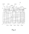
- FIGs. 3 and 4 are diagrams schematically showing a method of winding the three conducting wires 53.
- illustration of the insulator 52 is omitted.
- illustration of an outer connecting wire portion 621 is omitted except for a portion.
- Fig. 5 is a diagram when the stator 22 is viewed from the position of an arrow P in Fig. 4 .
- the motor 1 is a three-phase synchronous type motor which is driven by a three-phase alternating current, that is, first phase, second phase, and third phase alternating currents.
- the first phase, second phase, and third phase currents respectively flow through the three conducting wires 53.
- the conducting wire 53 through which the first phase current flows is referred to as a first conducting wire W1
- the conducting wire 53 through which the second phase current flows is referred to as a second conducting wire W2
- the conducting wire 53 through which the third phase current flows is referred to as a third conducting wire W3.
- the first conducting wire W1, the second conducting wire W2, and the third conducting wire W3 are wound around the insulator 52 in this order.
- the stator 22 in this embodiment has twelve teeth 512.
- the tooth 512 around which the first conducting wire W1 is first wound is referred to as a first tooth T1.
- other teeth 512 are referred to as a second tooth T2, a third tooth T3, ..., and a twelfth tooth T12 in a clockwise direction when viewed from the upper side in the axial direction.
- the first conducting wire W1 extends axially downward toward the first tooth T1 from above the first tooth T1 and is first wound around the first tooth T1.
- the first conducting wire W1 extends from the first tooth T1 to the fourth tooth T4 in the circumferential direction and is wound around the fourth tooth T4.
- the first conducting wire W1 extends from the fourth tooth T4 to the seventh tooth T7 in the circumferential direction and is wound around the seventh tooth T7.
- the first conducting wire W1 extends from the seventh tooth T7 to the tenth tooth T10 in the circumferential direction and is wound around the tenth tooth T10. Thereafter, the first conducting wire W1 is axially led out upward from the tenth tooth T10.
- the first conducting wire W1 has the four winding wire portions 61 which are formed around the first tooth T1, the fourth tooth T4, the seventh tooth T7, and the tenth tooth T10, three connecting wire portions 62 performing relay between the winding wire portions 61, the lead-out wire portion 63 of a winding start, and the lead-out wire portion 64 of a winding end.
- All of the three connecting wire portions 62 of the first conducting wire W1 pass through the outside in the radial direction of the wall portion 522 of the insulator 52. That is, the three connecting wire portions 62 of the first conducting wire W1 are configured with only the outer connecting wire portion 621 which passes through the outside in the radial direction of the wall portion 522.
- the lead-out wire portion 63 of a winding start extends axially downward toward the winding wire portion 61 of the first tooth T1 which is first wound.
- the lead-out wire portion 64 of a winding end extends axially upward from the winding wire portion 61 of the tenth tooth T10 which is last wound.
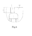
- Fig. 6 is a diagram when the wall portion 522 of the insulator 52 is viewed from the position of an arrow A in Fig. 4 .
- the wall portion 522 has a first cutout 71 on the outside in the radial direction of the tenth tooth T10.
- the wall portion 522 has the first cutouts 71 having the same depth on the outside in the radial direction of the first tooth T1, the fourth tooth T4, and the seventh tooth T7 as well.
- the first cutout 71 is recessed downward from an upper edge portion of the wall portion 522 and radially penetrates the wall portion 522.
- the first conducting wire W1 passes through the first cutouts 71 when heading from the outer connecting wire portion 621 to the winding wire portion 61 and when heading from the winding wire portion 61 to the outer connecting wire portion 621.
- the second conducting wire W2 extends axially downward toward the eleventh tooth T11 from above the eleventh tooth T11 and is first wound around the eleventh tooth T11.
- the second conducting wire W2 extends from the eleventh tooth T11 to the eighth tooth T8 in the circumferential direction and is wound around the eighth tooth T8.
- the second conducting wire W2 extends from the eighth tooth T8 to the fifth tooth T5 in the circumferential direction and is wound around the fifth tooth T5.
- the second conducting wire W2 extends from the fifth tooth T5 to the second tooth T2 in the circumferential direction and is wound around the second tooth T2. Thereafter, the second conducting wire W2 is axially led out upward from the second tooth T2.
- the second conducting wire W2 has the four winding wire portions 61 which are formed around the eleventh tooth T11, the eighth tooth T8, the fifth tooth T5, and the second tooth T2, the three connecting wire portions 62 performing relay between the winding wire portions 61, the lead-out wire portion 63 of a winding start, and the lead-out wire portion 64 of a winding end.
- the connecting wire portion 62 connecting the eleventh tooth T11 and the eighth tooth T8 includes an inner connecting wire portion 622 which passes through the inside in the radial direction of the wall portion 522, and the outer connecting wire portion 621 which passes through the outside in the radial direction of the wall portion 522.
- the other two connecting wire portions 62 are configured with only the outer connecting wire portion 621 which passes through the outside in the radial direction of the wall portion 522.
- the lead-out wire portion 63 of a winding start extends axially downward toward the winding wire portion 61 of the eleventh tooth T11 which is first wound.
- the lead-out wire portion 64 of a winding end extends axially upward from the winding wire portion 61 of the second tooth T2 which is last wound.
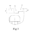
- Fig. 7 is a diagram when the wall portion 522 of the insulator 52 is viewed from the position of an arrow B in Fig. 4 .
- the wall portion 522 has a second cutout 72 on the outside in the radial direction of the eleventh tooth T11. Further, the wall portion 522 has the second cutouts 72 having the same depth on the outside in the radial direction of the second tooth T2, the fifth tooth T5, and the eighth tooth T8 as well.
- the second cutout 72 is recessed downward from the upper edge portion of the wall portion 522 and radially penetrates the wall portion 522.
- the second conducting wire W2 passes through the second cutouts 72 when heading from the outer connecting wire portion 621 to the winding wire portion 61 and when heading from the winding wire portion 61 to the outer connecting wire portion 621.
- the winding of the second conducting wire W2 is completed, subsequently, the winding of the third conducting wire W3 is performed.
- the third conducting wire W3 extends axially downward toward the third tooth T3 from above the third tooth T3 and is first wound around the third tooth T3.
- the third conducting wire W3 extends from the third tooth T3 to the sixth tooth T6 in the circumferential direction and is wound around the sixth tooth T6.
- the third conducting wire W3 extends from the sixth tooth T6 to the ninth tooth T9 in the circumferential direction and is wound around the ninth tooth T9.
- the third conducting wire W3 extends from the ninth tooth T9 to the twelfth tooth T12 in the circumferential direction and is wound around the twelfth tooth T12. Thereafter, the third conducting wire W3 is axially led out upward from the twelfth tooth T12.
- the third conducting wire W3 has the four winding wire portions 61 which are formed around the third tooth T3, the sixth tooth T6, the ninth tooth T9, and the twelfth tooth T12, the three connecting wire portions 62 performing relay between the winding wire portions 61, the lead-out wire portion 63 of a winding start, and the lead-out wire portion 64 of a winding end.
- the connecting wire portion 62 connecting the ninth tooth T9 and the twelfth tooth T12 includes the inner connecting wire portion 622 which passes through the inside in the radial direction of the wall portion 522, and the outer connecting wire portion 621 which passes through the outside in the radial direction of the wall portion 522.
- the other two connecting wire portions 62 are configured with only the outer connecting wire portion 621 which passes through the outside in the radial direction of the wall portion 522.
- the lead-out wire portion 63 of a winding start extends axially downward toward the winding wire portion 61 of the third tooth T3 which is first wound.
- the lead-out wire portion 64 of a winding end extends axially upward from the winding wire portion 61 of the twelfth tooth T12 which is last wound.
- Fig. 8 is a diagram when the wall portion 522 of the insulator 52 is viewed from the position of an arrow C in Fig. 4 .
- the wall portion 522 has a third cutout 73 on the outside in the radial direction of the twelfth tooth T12.
- the wall portion 522 has the third cutouts 73 having the same depth on the outside in the radial direction of the third tooth T3, the sixth tooth T6, and the ninth tooth T9 as well.
- the third cutout 73 is recessed downward from the upper edge portion of the wall portion 522 and radially penetrates the wall portion 522.
- the third conducting wire W3 passes through the third cutouts 73 when heading from the outer connecting wire portion 621 to the winding wire portion 61 and when heading from the winding wire portion 61 to the outer connecting wire portion 621.
- each of the plurality of cutouts 71 to 73 in this embodiment has a depth corresponding to the phase of the winding wire portion 61 which is located radially on the inside thereof. That is, the axial depths of the cutouts 71 to 73 are different for each phase of the conducting wires 53 which pass through the cutouts 71 to 73.
- the outer connecting wire portion 621 of the second conducting wire W2 is disposed on the upper side of the outer connecting wire portion 621 of the first conducting wire W1 and the outer connecting wire portion 621 of the third conducting wire W3 is disposed further on the upper side. Then, the outer connecting wire portions 621 of the respective phases can be prevented from overlapping in the radial direction. As a result, the radial dimension of the stator 22 can be reduced.
- an additional cutout 74 is provided in the wall portion 522 of the insulator 52. As shown in Fig. 7 , the additional cutout 74 is provided next to the second cutout 72 which is located on the outside in the radial direction of the eleventh tooth T11. The second cutout 72 and the additional cutout 74 are connected to each other. An axial depth d4 of the additional cutout 74 is shallower than the axial depth d2 of the second cutout 72 adjacent thereto.
- the third conducting wire W3 passes through the additional cutout 74 when heading from the inner connecting wire portion 622 to the outer connecting wire portion 621.
- the axial depth d4 of the additional cutout 74 is a depth corresponding to the third phase. That is, the axial depth d4 of the additional cutout 74 and the axial depth d3 of the third cutout 73 are made to be equal to each other. In this manner, by providing the additional cutout 74, it is possible to stabilize the positions and the heights of the inner connecting wire portion 622 and the outer connecting wire portion 621 of the third conducting wire W3.
- the inner connecting wire portion 622 of the second conducting wire W2 passes through the inside in the radial direction of the lead-out wire portion 64 of a winding end of the first conducting wire W1.
- the interference of the connecting wire portion 62 of the second conducting wire W2 with the lead-out wire portion 64 of the first conducting wire W1 further on the outside in the radial direction than the wall portion 522 can be avoided. That is, the connecting wire portion 62 of the second conducting wire W2 and the lead-out wire portion 64 of the first conducting wire W1 do not radially overlap each other further on the outside in the radial direction than the wall portion 522.
- the connecting wire portion 62 of the second conducting wire W2 is disposed while avoiding the lead-out wire portion 64 of the first conducting wire W1. In this way, the radially outward protrusion of a conducting wire is suppressed, and thus it is possible to reduce the radial dimension of the entirety of the motor 1.
- the inner connecting wire portion 622 of the second conducting wire W2 comes into contact with the radially inner surface of the lead-out wire portion 64 of a winding end of the first conducting wire W1.
- fluctuation of the position of the lead-out wire portion 64 of the first conducting wire W1 can be suppressed by pushing the lead-out wire portion 64 of the first conducting wire W1 by the inner connecting wire portion 622 of the second conducting wire W2.
- the second conducting wire W2 passes through the first cutout 71 when heading from the inner connecting wire portion 622 to the outer connecting wire portion 621.
- the lead-out wire portion 64 of the first conducting wire W1 can be suppressed from protruding radially outward from the first cutout 71. Further, at the time of the manufacturing of the motor 1, the lead-out wire portion 64 of the first conducting wire W1 can be easily connected to the bus bar 231.
- the inner connecting wire portion 622 of the third conducting wire W3 passes through the inside in the radial direction of the lead-out wire portion 64 of a winding end of the first conducting wire W1 and the lead-out wire portion 63 of a winding start of the second conducting wire W2.
- the connecting wire portion 62 of the third conducting wire W3 can avoid interfering with the lead-out wire portion 64 of the first conducting wire W1 and the lead-out wire portion 63 of the second conducting wire W2 further on the outside in the radial direction than the wall portion 522.
- the connecting wire portion 62 of the third conducting wire W3 does not radially overlap with the lead-out wire portion 64 of the first conducting wire W1 and the lead-out wire portion 63 of the second conducting wire W2 further on the outside in the radial direction than the wall portion 522.
- the connecting wire portion 62 of the third conducting wire W3 is disposed while avoiding the lead-out wire portion 64 of the first conducting wire W1 and the lead-out wire portion 63 of the second conducting wire W2. In this way, the radially outward protrusion of a conducting wire is suppressed, and thus it is possible to reduce the radial dimension of the entirety of the motor 1.
- the outer connecting wire portion 621 and the inner connecting wire portion 622 of the second conducting wire W2 are disposed between the winding wire portion 61 of the eleventh tooth T11 and the winding wire portion 61 of the eighth tooth T8. Further, the outer connecting wire portion 621 and the inner connecting wire portion 622 of the third conducting wire W3 are disposed between the winding wire portion 61 of the ninth tooth T9 and the winding wire portion 61 of the twelfth tooth T12. At these locations, the outer connecting wire portion 621 and the inner connecting wire portion 622 are continuous without intervention of the other winding wire portions 61. Then, the second conducting wire W2 and the third conducting wire W3 cross the wall portion 522 at the boundary between the outer connecting wire portion 621 and the inner connecting wire portion 622.
- the connecting wire portion 62 of the first conducting wire W1 is wound in the clockwise direction from the first tooth T1 to the tenth tooth T10 when viewed from the upper side in the axial direction.
- the connecting wire portion 62 of the third conducting wire W3 is wound in the clockwise direction from the third tooth T3 to the twelfth tooth T12 when viewed from the upper side in the axial direction.
- the respective winding wire portions 61 of the first conducting wire W1 and the third conducting wire W3 are wound in the counterclockwise direction when viewed from the inside in the radial direction.
- the connecting wire portion 62 of the second conducting wire W2 is wound in the counterclockwise direction from the eleventh tooth T11 to the second tooth T2 when viewed from the upper side in the axial direction. Then, the respective winding wire portions 61 of the second conducting wire W2 are wound in the clockwise direction when viewed from the inside in the radial direction.
- the connecting wire portions 62 of the first conducting wire W1 and the third conducting wire W3 and the connecting wire portion 62 of the second conducting wire W2 are disposed in directions opposite to each other in the circumferential direction. Further, the winding wire portions 61 of the first conducting wire W1 and the third conducting wire W3 and the winding wire portions 61 of the second conducting wire W2 are wound around the teeth insulating portions 521 in directions opposite to each other.
- the inner connecting wire portion 622 extends from the winding wire portion 61 of the eleventh tooth T11. Therefore, when forming the winding wire portion 61 of the eleventh tooth T11, the inner connecting wire portion 622 is not yet present, and therefore, it is easy to wind the second conducting wire W2.
- a lower end portion of the lead-out wire portion 63 of a winding start of the second conducting wire W2 comes into contact with the radially outermost portion of the winding wire portion 61 of the eleventh tooth T11.
- the fluctuation of the position of the second conducting wire W2 is suppressed. Therefore, the radially outward protrusion of the second conducting wire W2 can be further suppressed.
- the contact of the lead-out wire portion 63 of the second conducting wire W2 with the inner connecting wire portion 622 of the third conducting wire W3 can be suppressed.
- the lead-out wire portion 63 of the second conducting wire W2 can be easily connected to the bus bar 231.
- the insulator 52 in this embodiment has a fixing groove 75, separately from the third cutout 73, on the outside in the radial direction of the twelfth tooth T12.
- the circumferential width of the fixing groove 75 is approximately the same as the diameter of the third conducting wire W3.
- the lead-out wire portion 64 of a winding end of the third conducting wire W3 which is last wound at the time of manufacturing is fitted into the fixing groove 75, thereby being fixed. Then, the third conducting wire W3 can be prevented from falling down radially inward at the time of manufacturing. In this way, the contact of the third conducting wire W3 with the rotor 32 can be prevented.
- the inner connecting wire portions are provided in the second conducting wire and the third conducting wire among the three conducting wires.
- the conducting wire having the inner connecting wire portion may be only one.
- Fig. 9 is a diagram when a motor 1 B according to an modified example is viewed from the upper side in the axial direction.
- a connecting wire portion 62B of a first conducting wire W1B is configured to have an outer connecting wire portion 621 B and an inner connecting wire portion 622B. That is, in the example of Fig. 9 , the inner connecting wire portion 622B is provided in not only a second conducting wire W2B and a third conducting wire W3B, but also in the first conducting wire W1B.
- the inner connecting wire portions 622B are provided in all the conducting wires W1B, W2B, and W3B, the total lengths of the conducting wires W1 B, W2B, and W3B can be shortened as a whole.
- the inner connecting wire portion may be disposed at a circumferential position different from that of the lead-out wire portions of other conducting wires.
- the total length of the conducting wire can be further shortened by making the connecting wire portion pass through the inside in the radial direction of the wall portion at the position which does not originally interfere with the lead-out wire portion.
- each member may be different from the shape shown in each drawing of this application. Further, the respective elements which appear in the above-described embodiments or modified example may be appropriately combined to the extent that conflict does not occur.
- the invention relates to, for example, a "motor which is an inner rotor type polyphase synchronous motor and has a plurality of conducting wires through which electric currents of the respective phases of a polyphase alternating current flow, wherein each of the plurality of conducting wires includes a plurality of winding wire portions which are arranged around a central axis extending up and down, a connecting wire portion which performs relay between the plurality of winding wire portions, and a lead-out wire portion extending axially upward from the winding wire portion, the connecting wire portion passes through an arc-shaped first route centered on the central axis in principle, but, a portion of the connecting wire portion of at least one conducting wire passes through a second route further on the inside in the radial direction than the first route, whereby interference of the connecting wire portion with the lead-out wire portions of other conducting wires is avoided".
- the "first route” is illustrated, in the above-described embodiments, as a route along the outer circumferential surface of the wall portion 522.
- the “second route” is illustrated, in the above-described embodiments, as a route which passes through further on the inside in the radial direction than the wall portion 522. According to this invention, the interference of the connecting wire portion with the lead-out wire portions of other conducting wires on the first route can be avoided. In this way, it is possible to reduce the radial dimension of the motor.
- the present invention can be applied to a motor.
Landscapes
- Engineering & Computer Science (AREA)
- Power Engineering (AREA)
- Insulation, Fastening Of Motor, Generator Windings (AREA)
- Windings For Motors And Generators (AREA)
- Manufacture Of Motors, Generators (AREA)
Abstract
Description
- The present invention relates to a motor.
- In the past, many in-vehicle motors have been mounted on transportation equipment such as an automobile. For a reduction in environmental load, a space saving and a reduction in weight are required for an in-vehicle component. For this reason, in the field of the in-vehicle motor, a reduction in the size of the motor has progressed. In order to realize a reduction in the size of a motor, it is necessary to compactly wind a conducting wire around an insulator of a stator. Further, also in motors which are used for other uses, due to limitation of a mounting space, or the like, there is a case where it is necessary to compactly wind a conducting wire.
- In general, in a manufacturing process of a three-phase synchronous motor, three conducting wires corresponding to the respective phases of a three-phase current are wound by using a winding machine. Each conducting wire forms a plurality of winding wire portions around teeth. Further, the plurality of winding wire portions are connected by connecting wires. The connecting wires are disposed so as to extend in a circumferential direction along the radially outer surface of an insulator. Further, an end portion of each conducting wire is led out from the winding wire portion and connected to a connection destination such as a bus bar.
- Conducting wire winding methods in motors of the related art are described in the specifications of, for example, Japanese Patent Nos.
4704177 4860339 - An object of the present invention is to provide a technique capable of reducing the radial dimension of a motor by devising a method of winding a conducting wire.
- This object is achieved by a motor of
claim 1. - The invention is based on the inventors' findings that in a case where a bus bar or the like which is a connection destination of a conducting wire is located on the upper side in an axial direction of a stator, it is necessary for an end portion of each conducting wire to be led out axially upward from a winding wire portion. If so, there is a case where a connecting wire of the conducting wire which is wound second or later and a lead-out wire of the previously wound conducting wire interfere with each other. In this case, the connecting wire of the conducting wire which is wound second or later and the lead-out wire of the previously wound conducting wire are disposed so as to radially overlap on the outside in the radial direction of a wall portion. As a result, the conducting wire partially protrudes radially outward, and thus there is a problem in which the radial dimension of the entire motor increases.
- A motor according to an exemplary first invention of this application has a stator, and a rotor which is rotatably supported on the inside in a radial direction of the stator. The stator has a stator core which is a magnetic body, an insulator mounted on the stator core, and first, second, and third conducting wires which are wound around the insulator and through which electric currents of the respective phases of a three-phase alternating current flow. The stator core has a core back which is seamlessly connected in an annular shape around a central axis extending up and down, and a plurality of teeth extending radially inward from the core back. The insulator has a teeth insulating portion which is interposed between each of the teeth and the conducting wire, and a wall portion extending in a circumferential direction further on the outside in the radial direction and on the upper side than the teeth insulating portion. Each of the first, second, and third conducting wires includes a plurality of winding wire portions which are wound around the teeth insulating portion, one or more connecting wire portions performing relay between the plurality of winding wire portions, and a lead-out wire portion extending axially upward from the winding wire portion. The one or more connecting wire portions of the first conducting wire have only outer connecting wire portions passing through the outside in the radial direction of the wall portion. The one or more connecting wire portions of the second and third conducting wires have outer connecting wire portions passing through the outside in the radial direction of the wall portion, and inner connecting wire portions passing through the inside in the radial direction of the wall portion. The inner connecting wire portion of the second conducting wire passes through the inside in the radial direction of the lead-out wire portion of the first conducting wire, and the inner connecting wire portion of the third conducting wire passes through the inside in the radial direction of the lead-out wire portion of the first conducting wire and the lead-out wire portion of the second conducting wire.
- A motor according to an exemplary second invention of this application has a stator, and a rotor which is rotatably supported on the inside in a radial direction of the stator. The stator has a stator core which is a magnetic body, an insulator mounted on the stator core, and first, second, and third conducting wires which are wound around the insulator and through which electric currents of the respective phases of a three-phase alternating current flow. The stator core has a core back which is seamlessly connected in an annular shape around a central axis extending up and down, and a plurality of teeth extending radially inward from the core back. The insulator has a teeth insulating portion which is interposed between each of the teeth and the conducting wire, and a wall portion extending in a circumferential direction further on the outside in the radial direction and on the upper side than the teeth insulating portion. Each of the first, second, and third conducting wires includes a plurality of winding wire portions which are wound around the teeth insulating portion, one or more connecting wire portions performing relay between the plurality of winding wire portions, and a lead-out wire portion extending axially upward from the winding wire portion. The one or more connecting wire portions of at least one conducting wire have outer connecting wire portions passing through the outside in the radial direction of the wall portion, and inner connecting wire portions passing through the inside in the radial direction of the wall portion. The outer connecting wire portion and the inner connecting wire portion are continuous, and the at least one conducting wire crosses the wall portion at a boundary between the outer connecting wire portion and the inner connecting wire portion.
- According to the exemplary first invention of this application, the interference of the connecting wire portion with the lead-out wire portions of other conducting wires can be avoided. For this reason, the connecting wire portion and the lead-out wire portion do not radially overlap further on the outside in the radial direction than the wall portion. In this way, it is possible to reduce the radial dimension of the motor.
- According to the exemplary second invention of this application, at least one conducting wire has the outer connecting wire portion and the inner connecting wire portion. In this way, it is possible to dispose the connecting wire portion while avoiding interference with the lead-out wire portions of other conducting wires. As a result, it is possible to reduce the radial dimension of the motor. Further, since the outer connecting wire portion and the inner connecting wire portion are continuous, radially inward protrusion of the inner connecting wire portion can be suppressed.
-
-
Fig. 1 is a diagram when a motor according to a first embodiment is viewed from the upper side in an axial direction. -
Fig. 2 is a vertical cross-sectional view of a motor according to a second embodiment. -
Fig. 3 is a diagram schematically showing a method of winding three conducting wires. -
Fig. 4 is a diagram schematically showing the method of winding three conducting wires. -
Fig. 5 is a diagram when a stator is viewed from the position of an arrow P inFig. 4 . -
Fig. 6 is a diagram when a wall portion of an insulator is viewed from the position of an arrow A inFig. 4 . -
Fig. 7 is a diagram when a wall portion of an insulator is viewed from the position of an arrow B inFig. 4 . -
Fig. 8 is a diagram when a wall portion of an insulator is viewed from the position of an arrow C inFig. 4 . -
Fig. 9 is a diagram when a motor according to a modified example is viewed from the upper side in the axial direction. - Hereinafter, exemplary embodiments of the present invention will be described with reference to the drawings. In addition, in this application, a direction parallel to a central axis of a motor is referred to as an "axial direction", a direction orthogonal to the central axis of the motor is referred to as a "radial direction", and a direction along an arc centered on the central axis of the motor is referred to as a "circumferential direction". Further, in this application, the shape or the positional relationship of each portion will be described with the axial direction set to be a vertical direction and the side of a lead-out wire portion with respect to a winding wire portion set to be the top. However, the definition of the vertical direction is not intended to limit a direction at the time of the manufacturing and the time of the use of a motor according to the present invention.
- Further, in this application, a "direction parallel to" also includes a direction substantially parallel to. Further, in this application, a "direction orthogonal to" also includes a direction substantially orthogonal to.
-
Fig. 1 is a diagram when a motor 1A according to a first embodiment of the present invention is viewed from the upper side in the axial direction. As shown inFig. 1 , the motor 1A has astator 22A and arotor 32A. Therotor 32A is rotatably supported on the inside in the radial direction of thestator 22A. - The
stator 22A has astator core 51A which is a magnetic body, and aninsulator 52A mounted on thestator core 51A. Thestator core 51A has a core back 511 A and a plurality ofteeth 512A. The core back 511A is seamlessly connected in an annular shape around acentral axis 9A. The plurality ofteeth 512A extend radially inward from the core back 511A. - The
insulator 52A has ateeth insulating portion 521 A and awall portion 522A. Theteeth insulating portion 521A is interposed between each of theteeth 512A and a windingwire portion 61A (described later). Thewall portion 522A extends in the circumferential direction further on the outside in the radial direction and the on upper side than theteeth insulating portion 521A. - A first conducting wire W1A, a second conducting wire W2A, and a third conducting wire W3A are wound around the
insulator 52A. Electric currents of the respective phases of a three-phase alternating current respectively flow through the first conducting wire W1A, the second conducting wire W2A, and the third conducting wire W3A. Each of the conducting wires W1A, W2A, and W3A includes two windingwire portions 61A, a single connectingwire portion 62A, and two lead-out wire portions 63A. The windingwire portion 61A is wound around theteeth insulating portion 521A of theinsulator 52A. The connectingwire portion 62A performs relay between the plurality of windingwire portions 61A. The lead-out wire portion 63A extends axially upward from the windingwire portion 61A of a winding start or a winding end. - As shown in
Fig. 1 , the connectingwire portion 62A of the first conducting wire W1A passes through further on the outside in the radial direction than thewall portion 522A of theinsulator 52A. That is, the connectingwire portion 62A of the first conducting wire W1A has only an outer connectingwire portion 621A passing through the outside in the radial direction of thewall portion 522A. On the other hand, each of the connectingwire portions 62A of the second conducting wire W2A and the third conducting wire W3A has an outer connectingwire portion 621A passing through the outside in the radial direction of thewall portion 522A, and an inner connectingwire portion 622A passing through the inside in the radial direction of thewall portion 522A. - The inner connecting
wire portion 622A of the second conducting wire W2A passes through the inside in the radial direction of the lead-out wire portion 63A of a winding end of the first conducting wire W1A. For this reason, it is possible to avoid the lead-out wire portion 63A of the first conducting wire W1A and the connectingwire portion 62A of the second conducting wire W2A interfering with each other further on the outside in the radial direction than thewall portion 522A. That is, the lead-out wire portion 63A of the first conducting wire W1A and the connectingwire portion 62A of the second conducting wire W2A do not radially overlap further on the outside in the radial direction than thewall portion 522A. - The third conducting wire W3A has two inner connecting
wire portions 622A. The inner connectingwire portion 622A on one side of the third conducting wire W3A passes through the inside in the radial direction of the lead-out wire portion 63A of a winding end of the first conducting wire W1A. The inner connectingwire portion 622A on the other side of the third conducting wire W3A passes through the inside in the radial direction of the lead-out wire portion 63A of a winding end of the second conducting wire W2A. For this reason, it is possible to avoid the connectingwire portion 62A of the third conducting wire W3A interfering with the lead-out wire portion 63A of the first conducting wire W1A and the connectingwire portion 63A of the second conducting wire W2A further on the outside in the radial direction than thewall portion 522A. That is, the lead-out wire portion 63A of the first conducting wire W1A and the lead-out wire portion 63A of the second conducting wire W2A do not radially overlap with the lead-out wire portion 62A of the third conducting wire W3A further on the outside in the radial direction than thewall portion 522A. - In this manner, in the motor 1A, the connecting
wire portions 62A of the second conducting wire W2A and the third conducting wire W3A are disposed while avoiding interference with the lead-out wire portion 63A of the other conducting wire. In this way, radial overlap of the conducting wires further on the outside in the radial direction of thewall portion 522A is avoided. As a result, it is possible to reduce the radial dimension of the motor 1 A. - Further, the outer connecting
wire portion 621A and the inner connectingwire portion 622A of the second conducting wire W2A are continuous with each other. The second conducting wire W2A crosses thewall portion 522A at the boundary between the inner connectingwire portion 622A and the outer connectingwire portion 621A. Further, the pair of outer connectingwire portion 621A and inner connectingwire portion 622A of the third conducting wire W3A is continuous with each other. The third conducting wire W3A crosses thewall portion 522A at the boundary between the inner connectingwire portion 622A and the outer connectingwire portion 621A. In this manner, if the outer connectingwire portion 621A and the inner connectingwire portion 622A are provided continuously, it is possible to suppress the radially inward protrusion of the inner connectingwire portion 622A. This is because the radial position of the outer connectingwire portion 621A is fixed by thewall portion 522A and therefore, the radially inward movement of the inner connectingwire portion 622A which is continuous with the outer connectingwire portion 621A is also restricted. Therefore, the inner connectingwire portion 622A can be prevented from coming into contact with therotor 32A. - Subsequently, a second embodiment of the present invention will be described.
Fig. 2 is a vertical cross-sectional view of amotor 1 according to the second embodiment. Themotor 1 according to this embodiment is mounted on, for example, an automobile and used in order to generate the driving force of a power steering. However, the motor according to the present invention may be used for uses other than the power steering. For example, the motor according to the present invention may be used as a drive source of the other site of an automobile, for example, a fan for engine cooling or an oil pump. Further, the motor according to the present invention may also be mounted on home electric appliances, office automation (OA) equipment, medical equipment, or the like, thereby generating various driving forces. - The
motor 1 is an inner rotor type motor in which arotor 32 is disposed radially inside astator 22. As shown inFig. 2 , themotor 1 has astationary section 2 and arotating section 3. Thestationary section 2 is fixed to a frame body of equipment which is a drive target. Therotating section 3 is supported so as to be able to rotate with respect to thestationary section 2. - The
stationary section 2 in this embodiment has ahousing 21, thestator 22, abus bar unit 23, alower bearing section 24, and anupper bearing section 25. - The
housing 21 has afirst housing member 41 and asecond housing member 42. Thefirst housing member 41 has a firsttubular portion 411, abottom plate portion 412, and afirst flange portion 413. The firsttubular portion 411 axially extends in a substantially cylindrical shape radially outside thestator 22. Thebottom plate portion 412 extends substantially perpendicular to acentral axis 9 on the lower side of thestator 22. Anopening 414 for disposing a shaft 31 (described later) is provided at the center of thebottom plate portion 412. Thefirst flange portion 413 extends radially outward from an upper end portion of the firsttubular portion 411. - The
second housing member 42 has a secondtubular portion 421, atop plate portion 422, and asecond flange portion 423. The secondtubular portion 421 axially extends in a substantially cylindrical shape radially outside thebus bar unit 23. Thetop plate portion 422 extends substantially perpendicular to thecentral axis 9 on the upper side of thebus bar unit 23. Thesecond flange portion 423 extends radially outward from a lower end portion of the secondtubular portion 421. - The
first housing member 41 and thesecond housing member 42 are configured by metal such as aluminum or stainless steel, for example. Thefirst flange portion 413 of thefirst housing member 41 and thesecond flange portion 423 of thesecond housing member 42 are fixed to each other by screws (not shown). Thestator 22, thebus bar unit 23, and the rotor 32 (described later) are accommodated in an internal space of thehousing 21 surrounded by the firsttubular portion 411, the secondtubular portion 421, thebottom plate portion 412, and thetop plate portion 422. - The
stator 22 has astator core 51, aninsulator 52 mounted on thestator core 51, and aconducting wire 53 wound around theinsulator 52. A laminated steel plate which is a magnetic body is used for thestator core 51. Thestator core 51 has a core back 511 having an annular shape, and a plurality ofteeth 512 extending radially inward from the core back 511. The core back 511 is disposed substantially coaxially with thecentral axis 9. Further, the core back 511 is seamlessly connected around thecentral axis 9. The outer circumferential surface of the core back 511 is fixed to the inner circumferential surface of the firsttubular portion 411 of thehousing 21. The plurality ofteeth 512 are arranged at substantially regular intervals in the circumferential direction. - The
insulator 52 is made of resin which is an insulator. Theinsulator 52 has ateeth insulating portion 521, awall portion 522, and a leading endconvex portion 523. Theteeth insulating portion 521 covers the upper surface, the lower surface, and both end surfaces in the circumferential direction of each of theteeth 512. Thewall portion 522 and the leading endconvex portion 523 are respectively located radially outside and radially inside a winding wire portion 61 (described later). On the upper side of thestator core 51, thewall portion 522 extends in the circumferential direction further on the outside in the radial direction and on the upper side than theteeth insulating portion 521. - In this embodiment, three conducting
wires 53 are wound around theinsulator 52. Each of the conductingwires 53 has a plurality of windingwire portions 61 wound around theteeth insulating portions 521. That is, in this embodiment, the windingwire portion 61 of each of the conductingwires 53 is wound around theteeth 512 with theteeth insulating portion 521 interposed therebetween. The plurality of windingwire portions 61 are arranged at substantially regular intervals in the circumferential direction. Theteeth insulating portion 521 is interposed between each of theteeth 512 and the windingwire portion 61, thereby preventing theteeth 512 and the windingwire portion 61 from electrically short-circuiting. - The
bus bar unit 23 has a plurality ofbus bars 231 made of metal such as copper which is an electric conductor, and abus bar holder 232 made of resin, which holds the plurality of bus bars 231. Lead-out wire portions 63 and 64 (described later) of each of the conductingwires 53 are connected to the plurality of bus bars 231. Further, thebus bar unit 23 has aconnector portion 233 protruding radially outward from an opening provided in a portion of the secondtubular portion 421 of thehousing 21. At the time of use of themotor 1, a conducting wire extending from an external power supply is connected to a terminal of theconnector portion 233. In this way, the external power supply and the three conductingwires 53 are electrically connected through the bus bars 231. - The
lower bearing section 24 is disposed between thebottom plate portion 412 of thehousing 21 and theshaft 31. Theupper bearing section 25 is disposed between thebus bar holder 232 and theshaft 31. A ball bearing in which an outer ring and an inner ring relatively rotate with balls interposed therebetween is used for each of thelower bearing section 24 and theupper bearing section 25 in this embodiment. In this way, theshaft 31 is rotatably supported with respect to thestationary section 2. However, instead of the ball bearing, other types of bearings such as a slide bearing or a fluid bearing may be used. - The
rotating section 3 in this embodiment has theshaft 31 and therotor 32. - The
shaft 31 is a columnar member extending along thecentral axis 9. As a material of theshaft 31, for example, stainless steel is used. Theshaft 31 rotates around thecentral axis 9 while being supported by thelower bearing section 24 and theupper bearing section 25 described above. Further, alower end portion 311 of theshaft 31 protrudes further to the lower side than thebottom plate portion 412 of thehousing 21. An apparatus which is a drive target is connected to thelower end portion 311 of theshaft 31 through a power transmission mechanism such as a gear. - The
rotor 32 is located radially inside thestator 22 and rotates along with theshaft 31. Therotor 32 has a plurality of magnets (not shown) arranged in the circumferential direction on the outer circumferential surface having a substantially cylindrical shape or on the inside. An N-polar magnetic pole face and an S-polar magnetic pole face are alternately arranged in the circumferential direction on the outer circumferential surface of therotor 32. In addition, instead of the plurality of magnets, a single annular magnet in which an N-pole and an S-pole are alternately magnetized in the circumferential direction may be used. - If a drive current is supplied from the external power supply to the
conducting wire 53 through theconnector portion 233 and thebus bar 231, an electric current flows through the plurality of windingwire portions 61. If so, magnetic flux is generated in theteeth 512 serving as magnetic cores of the windingwire portions 61. Then, circumferential torque is generated by the action of the magnetic flux between theteeth 512 and therotor 32. As a result, therotating section 3 rotates around thecentral axis 9 with respect to thestationary section 2. - Subsequently, a method of winding the three conducting
wires 53 around theinsulator 52 will be described in detail.Figs. 3 and4 are diagrams schematically showing a method of winding the three conductingwires 53. In order to avoid the drawings becoming complicated, inFig. 3 , illustration of theinsulator 52 is omitted. Further, inFig. 4 , illustration of an outer connecting wire portion 621 (described later) is omitted except for a portion. Further,Fig. 5 is a diagram when thestator 22 is viewed from the position of an arrow P inFig. 4 . - The
motor 1 according to this embodiment is a three-phase synchronous type motor which is driven by a three-phase alternating current, that is, first phase, second phase, and third phase alternating currents. The first phase, second phase, and third phase currents respectively flow through the three conductingwires 53. In the following, theconducting wire 53 through which the first phase current flows is referred to as a first conducting wire W1, theconducting wire 53 through which the second phase current flows is referred to as a second conducting wire W2, and theconducting wire 53 through which the third phase current flows is referred to as a third conducting wire W3. At the time of the manufacturing of themotor 1, the first conducting wire W1, the second conducting wire W2, and the third conducting wire W3 are wound around theinsulator 52 in this order. - Further, as shown in
Figs. 3 and4 , thestator 22 in this embodiment has twelveteeth 512. In the following, thetooth 512 around which the first conducting wire W1 is first wound is referred to as a first tooth T1. Then,other teeth 512 are referred to as a second tooth T2, a third tooth T3, ..., and a twelfth tooth T12 in a clockwise direction when viewed from the upper side in the axial direction. - As shown in
Fig. 3 , the first conducting wire W1 extends axially downward toward the first tooth T1 from above the first tooth T1 and is first wound around the first tooth T1. Next, the first conducting wire W1 extends from the first tooth T1 to the fourth tooth T4 in the circumferential direction and is wound around the fourth tooth T4. Subsequently, the first conducting wire W1 extends from the fourth tooth T4 to the seventh tooth T7 in the circumferential direction and is wound around the seventh tooth T7. Further, the first conducting wire W1 extends from the seventh tooth T7 to the tenth tooth T10 in the circumferential direction and is wound around the tenth tooth T10. Thereafter, the first conducting wire W1 is axially led out upward from the tenth tooth T10. - That is, the first conducting wire W1 has the four winding
wire portions 61 which are formed around the first tooth T1, the fourth tooth T4, the seventh tooth T7, and the tenth tooth T10, three connectingwire portions 62 performing relay between the windingwire portions 61, the lead-out wire portion 63 of a winding start, and the lead-out wire portion 64 of a winding end. - All of the three connecting
wire portions 62 of the first conducting wire W1 pass through the outside in the radial direction of thewall portion 522 of theinsulator 52. That is, the three connectingwire portions 62 of the first conducting wire W1 are configured with only the outer connectingwire portion 621 which passes through the outside in the radial direction of thewall portion 522. The lead-out wire portion 63 of a winding start extends axially downward toward the windingwire portion 61 of the first tooth T1 which is first wound. The lead-out wire portion 64 of a winding end extends axially upward from the windingwire portion 61 of the tenth tooth T10 which is last wound. -
Fig. 6 is a diagram when thewall portion 522 of theinsulator 52 is viewed from the position of an arrow A inFig. 4 . As shown inFig. 6 , thewall portion 522 has afirst cutout 71 on the outside in the radial direction of the tenth tooth T10. Further, thewall portion 522 has thefirst cutouts 71 having the same depth on the outside in the radial direction of the first tooth T1, the fourth tooth T4, and the seventh tooth T7 as well. Thefirst cutout 71 is recessed downward from an upper edge portion of thewall portion 522 and radially penetrates thewall portion 522. The first conducting wire W1 passes through thefirst cutouts 71 when heading from the outer connectingwire portion 621 to the windingwire portion 61 and when heading from the windingwire portion 61 to the outer connectingwire portion 621. - If the winding of the first conducting wire W1 is completed, subsequently, the winding of the second conducting wire W2 is performed. As shown in
Fig. 3 , the second conducting wire W2 extends axially downward toward the eleventh tooth T11 from above the eleventh tooth T11 and is first wound around the eleventh tooth T11. Next, the second conducting wire W2 extends from the eleventh tooth T11 to the eighth tooth T8 in the circumferential direction and is wound around the eighth tooth T8. Subsequently, the second conducting wire W2 extends from the eighth tooth T8 to the fifth tooth T5 in the circumferential direction and is wound around the fifth tooth T5. Further, the second conducting wire W2 extends from the fifth tooth T5 to the second tooth T2 in the circumferential direction and is wound around the second tooth T2. Thereafter, the second conducting wire W2 is axially led out upward from the second tooth T2. - That is, the second conducting wire W2 has the four winding
wire portions 61 which are formed around the eleventh tooth T11, the eighth tooth T8, the fifth tooth T5, and the second tooth T2, the three connectingwire portions 62 performing relay between the windingwire portions 61, the lead-out wire portion 63 of a winding start, and the lead-out wire portion 64 of a winding end. - The connecting
wire portion 62 connecting the eleventh tooth T11 and the eighth tooth T8 includes an inner connectingwire portion 622 which passes through the inside in the radial direction of thewall portion 522, and the outer connectingwire portion 621 which passes through the outside in the radial direction of thewall portion 522. The other two connectingwire portions 62 are configured with only the outer connectingwire portion 621 which passes through the outside in the radial direction of thewall portion 522. The lead-out wire portion 63 of a winding start extends axially downward toward the windingwire portion 61 of the eleventh tooth T11 which is first wound. The lead-out wire portion 64 of a winding end extends axially upward from the windingwire portion 61 of the second tooth T2 which is last wound. -
Fig. 7 is a diagram when thewall portion 522 of theinsulator 52 is viewed from the position of an arrow B inFig. 4 . As shown inFig. 7 , thewall portion 522 has asecond cutout 72 on the outside in the radial direction of the eleventh tooth T11. Further, thewall portion 522 has thesecond cutouts 72 having the same depth on the outside in the radial direction of the second tooth T2, the fifth tooth T5, and the eighth tooth T8 as well. Thesecond cutout 72 is recessed downward from the upper edge portion of thewall portion 522 and radially penetrates thewall portion 522. The second conducting wire W2 passes through thesecond cutouts 72 when heading from the outer connectingwire portion 621 to the windingwire portion 61 and when heading from the windingwire portion 61 to the outer connectingwire portion 621. - If the winding of the second conducting wire W2 is completed, subsequently, the winding of the third conducting wire W3 is performed. As shown in
Fig. 3 , the third conducting wire W3 extends axially downward toward the third tooth T3 from above the third tooth T3 and is first wound around the third tooth T3. Next, the third conducting wire W3 extends from the third tooth T3 to the sixth tooth T6 in the circumferential direction and is wound around the sixth tooth T6. Subsequently, the third conducting wire W3 extends from the sixth tooth T6 to the ninth tooth T9 in the circumferential direction and is wound around the ninth tooth T9. Further, the third conducting wire W3 extends from the ninth tooth T9 to the twelfth tooth T12 in the circumferential direction and is wound around the twelfth tooth T12. Thereafter, the third conducting wire W3 is axially led out upward from the twelfth tooth T12. - That is, the third conducting wire W3 has the four winding
wire portions 61 which are formed around the third tooth T3, the sixth tooth T6, the ninth tooth T9, and the twelfth tooth T12, the three connectingwire portions 62 performing relay between the windingwire portions 61, the lead-out wire portion 63 of a winding start, and the lead-out wire portion 64 of a winding end. - The connecting
wire portion 62 connecting the ninth tooth T9 and the twelfth tooth T12 includes the inner connectingwire portion 622 which passes through the inside in the radial direction of thewall portion 522, and the outer connectingwire portion 621 which passes through the outside in the radial direction of thewall portion 522. The other two connectingwire portions 62 are configured with only the outer connectingwire portion 621 which passes through the outside in the radial direction of thewall portion 522. The lead-out wire portion 63 of a winding start extends axially downward toward the windingwire portion 61 of the third tooth T3 which is first wound. The lead-out wire portion 64 of a winding end extends axially upward from the windingwire portion 61 of the twelfth tooth T12 which is last wound. -
Fig. 8 is a diagram when thewall portion 522 of theinsulator 52 is viewed from the position of an arrow C inFig. 4 . As shown inFig. 8 , thewall portion 522 has athird cutout 73 on the outside in the radial direction of the twelfth tooth T12. Further, thewall portion 522 has thethird cutouts 73 having the same depth on the outside in the radial direction of the third tooth T3, the sixth tooth T6, and the ninth tooth T9 as well. Thethird cutout 73 is recessed downward from the upper edge portion of thewall portion 522 and radially penetrates thewall portion 522. The third conducting wire W3 passes through thethird cutouts 73 when heading from the outer connectingwire portion 621 to the windingwire portion 61 and when heading from the windingwire portion 61 to the outer connectingwire portion 621. - As shown in
Figs. 6 and7 , an axial depth d1 of thefirst cutout 71 is deeper than an axial depth d2 of thesecond cutout 72. Further, as shown inFigs. 7 and8 , the axial depth d2 of thesecond cutout 72 is deeper than an axial depth d3 of thethird cutout 73. In this manner, each of the plurality ofcutouts 71 to 73 in this embodiment has a depth corresponding to the phase of the windingwire portion 61 which is located radially on the inside thereof. That is, the axial depths of thecutouts 71 to 73 are different for each phase of the conductingwires 53 which pass through thecutouts 71 to 73. - In this way, it is possible to make the heights of the outer connecting
wire portions 621 of the respective phases different from each other. Specifically, as shown inFig. 5 , the outer connectingwire portion 621 of the second conducting wire W2 is disposed on the upper side of the outer connectingwire portion 621 of the first conducting wire W1 and the outer connectingwire portion 621 of the third conducting wire W3 is disposed further on the upper side. Then, the outer connectingwire portions 621 of the respective phases can be prevented from overlapping in the radial direction. As a result, the radial dimension of thestator 22 can be reduced. - Further, in this embodiment, separately from the
first cutout 71, thesecond cutout 72, and thethird cutout 73 which are basic cutouts, anadditional cutout 74 is provided in thewall portion 522 of theinsulator 52. As shown inFig. 7 , theadditional cutout 74 is provided next to thesecond cutout 72 which is located on the outside in the radial direction of the eleventh tooth T11. Thesecond cutout 72 and theadditional cutout 74 are connected to each other. An axial depth d4 of theadditional cutout 74 is shallower than the axial depth d2 of thesecond cutout 72 adjacent thereto. - Further, the third conducting wire W3 passes through the
additional cutout 74 when heading from the inner connectingwire portion 622 to the outer connectingwire portion 621. For this reason, the axial depth d4 of theadditional cutout 74 is a depth corresponding to the third phase. That is, the axial depth d4 of theadditional cutout 74 and the axial depth d3 of thethird cutout 73 are made to be equal to each other. In this manner, by providing theadditional cutout 74, it is possible to stabilize the positions and the heights of the inner connectingwire portion 622 and the outer connectingwire portion 621 of the third conducting wire W3. - As shown in
Figs. 3 to 5 , the inner connectingwire portion 622 of the second conducting wire W2 passes through the inside in the radial direction of the lead-out wire portion 64 of a winding end of the first conducting wire W1. In this way, the interference of the connectingwire portion 62 of the second conducting wire W2 with the lead-out wire portion 64 of the first conducting wire W1 further on the outside in the radial direction than thewall portion 522 can be avoided. That is, the connectingwire portion 62 of the second conducting wire W2 and the lead-out wire portion 64 of the first conducting wire W1 do not radially overlap each other further on the outside in the radial direction than thewall portion 522. In this manner, in themotor 1, the connectingwire portion 62 of the second conducting wire W2 is disposed while avoiding the lead-out wire portion 64 of the first conducting wire W1. In this way, the radially outward protrusion of a conducting wire is suppressed, and thus it is possible to reduce the radial dimension of the entirety of themotor 1. - In particular, as shown in
Fig. 5 , in this embodiment, the inner connectingwire portion 622 of the second conducting wire W2 comes into contact with the radially inner surface of the lead-out wire portion 64 of a winding end of the first conducting wire W1. In this manner, fluctuation of the position of the lead-out wire portion 64 of the first conducting wire W1 can be suppressed by pushing the lead-out wire portion 64 of the first conducting wire W1 by the inner connectingwire portion 622 of the second conducting wire W2. In this way, the radially inward protrusion of the first conducting wire W1 can be suppressed. In addition, the second conducting wire W2 passes through thefirst cutout 71 when heading from the inner connectingwire portion 622 to the outer connectingwire portion 621. In this way, the lead-out wire portion 64 of the first conducting wire W1 can be suppressed from protruding radially outward from thefirst cutout 71. Further, at the time of the manufacturing of themotor 1, the lead-out wire portion 64 of the first conducting wire W1 can be easily connected to thebus bar 231. - Further, as shown in
Figs. 3 to 5 , the inner connectingwire portion 622 of the third conducting wire W3 passes through the inside in the radial direction of the lead-out wire portion 64 of a winding end of the first conducting wire W1 and the lead-out wire portion 63 of a winding start of the second conducting wire W2. In this way, the connectingwire portion 62 of the third conducting wire W3 can avoid interfering with the lead-out wire portion 64 of the first conducting wire W1 and the lead-out wire portion 63 of the second conducting wire W2 further on the outside in the radial direction than thewall portion 522. That is, the connectingwire portion 62 of the third conducting wire W3 does not radially overlap with the lead-out wire portion 64 of the first conducting wire W1 and the lead-out wire portion 63 of the second conducting wire W2 further on the outside in the radial direction than thewall portion 522. In this manner, in themotor 1, the connectingwire portion 62 of the third conducting wire W3 is disposed while avoiding the lead-out wire portion 64 of the first conducting wire W1 and the lead-out wire portion 63 of the second conducting wire W2. In this way, the radially outward protrusion of a conducting wire is suppressed, and thus it is possible to reduce the radial dimension of the entirety of themotor 1. - Further, in this embodiment, the outer connecting
wire portion 621 and the inner connectingwire portion 622 of the second conducting wire W2 are disposed between the windingwire portion 61 of the eleventh tooth T11 and the windingwire portion 61 of the eighth tooth T8. Further, the outer connectingwire portion 621 and the inner connectingwire portion 622 of the third conducting wire W3 are disposed between the windingwire portion 61 of the ninth tooth T9 and the windingwire portion 61 of the twelfth tooth T12. At these locations, the outer connectingwire portion 621 and the inner connectingwire portion 622 are continuous without intervention of the other windingwire portions 61. Then, the second conducting wire W2 and the third conducting wire W3 cross thewall portion 522 at the boundary between the outer connectingwire portion 621 and the inner connectingwire portion 622. - In this manner, if the outer connecting
wire portion 621 and the inner connectingwire portion 622 are provided continuously, the radially inward protrusion of the inner connectingwire portion 622 can be suppressed. The reason is that the radial position of the outer connectingwire portion 621 is fixed by thewall portion 522, and therefore, the radially inward movement of the inner connectingwire portion 622 which is continuous with the outer connectingwire portion 621 is also restricted. In this way, the inner connectingwire portion 622 can be prevented from coming into contact with therotor 32. - Further, as shown in
Figs. 3 to 5 , in this embodiment, the connectingwire portion 62 of the first conducting wire W1 is wound in the clockwise direction from the first tooth T1 to the tenth tooth T10 when viewed from the upper side in the axial direction. Further, the connectingwire portion 62 of the third conducting wire W3 is wound in the clockwise direction from the third tooth T3 to the twelfth tooth T12 when viewed from the upper side in the axial direction. Then, the respective windingwire portions 61 of the first conducting wire W1 and the third conducting wire W3 are wound in the counterclockwise direction when viewed from the inside in the radial direction. In contrast, the connectingwire portion 62 of the second conducting wire W2 is wound in the counterclockwise direction from the eleventh tooth T11 to the second tooth T2 when viewed from the upper side in the axial direction. Then, the respective windingwire portions 61 of the second conducting wire W2 are wound in the clockwise direction when viewed from the inside in the radial direction. - In this manner, in this embodiment, the connecting
wire portions 62 of the first conducting wire W1 and the third conducting wire W3 and the connectingwire portion 62 of the second conducting wire W2 are disposed in directions opposite to each other in the circumferential direction. Further, the windingwire portions 61 of the first conducting wire W1 and the third conducting wire W3 and the windingwire portions 61 of the second conducting wire W2 are wound around theteeth insulating portions 521 in directions opposite to each other. - As in this embodiment, in a case where the inner connecting
wire portion 622 of the second conducting wire W2 is disposed radially inside the lead-out wire portion 64 of the first conducting wire W1, if an attempt to wind the windingwire portion 61 of the eleventh tooth T11 of the second conducting wire W2 in the same direction as the windingwire portion 61 of the first conducting wire W1 is made, a nozzle of a winding machine interferes with the inner connectingwire portion 622 of the second conducting wire W2, and thus it becomes difficult to form the windingwire portion 61 of the eleventh tooth T11 which is connected to the inner connectingwire portion 622. If the second conducting wire W2 is wound in the opposite direction to the first conducting wire W1, after the windingwire portion 61 of the eleventh tooth T11 of the second conducting wire W2 is formed, the inner connectingwire portion 622 extends from the windingwire portion 61 of the eleventh tooth T11. Therefore, when forming the windingwire portion 61 of the eleventh tooth T11, the inner connectingwire portion 622 is not yet present, and therefore, it is easy to wind the second conducting wire W2. - Further, in this embodiment, a lower end portion of the lead-
out wire portion 63 of a winding start of the second conducting wire W2 comes into contact with the radially outermost portion of the windingwire portion 61 of the eleventh tooth T11. In this way, the fluctuation of the position of the second conducting wire W2 is suppressed. Therefore, the radially outward protrusion of the second conducting wire W2 can be further suppressed. Further, the contact of the lead-out wire portion 63 of the second conducting wire W2 with the inner connectingwire portion 622 of the third conducting wire W3 can be suppressed. Further, at the time of the manufacturing of themotor 1, the lead-out wire portion 63 of the second conducting wire W2 can be easily connected to thebus bar 231. - Further, as shown in
Fig. 8 , theinsulator 52 in this embodiment has a fixinggroove 75, separately from thethird cutout 73, on the outside in the radial direction of the twelfth tooth T12. The circumferential width of the fixinggroove 75 is approximately the same as the diameter of the third conducting wire W3. The lead-out wire portion 64 of a winding end of the third conducting wire W3 which is last wound at the time of manufacturing is fitted into the fixinggroove 75, thereby being fixed. Then, the third conducting wire W3 can be prevented from falling down radially inward at the time of manufacturing. In this way, the contact of the third conducting wire W3 with therotor 32 can be prevented. - The exemplary embodiments of the present invention have been described above. However, the present invention is not limited to the above-described embodiments.
- In the embodiments described above, the inner connecting wire portions are provided in the second conducting wire and the third conducting wire among the three conducting wires. However, among the three conducting wires, the conducting wire having the inner connecting wire portion may be only one.
-
Fig. 9 is a diagram when amotor 1 B according to an modified example is viewed from the upper side in the axial direction. In the example ofFig. 9 , a connectingwire portion 62B of a first conducting wire W1B is configured to have an outer connectingwire portion 621 B and an inner connectingwire portion 622B. That is, in the example ofFig. 9 , the inner connectingwire portion 622B is provided in not only a second conducting wire W2B and a third conducting wire W3B, but also in the first conducting wire W1B. In this manner, if the inner connectingwire portions 622B are provided in all the conducting wires W1B, W2B, and W3B, the total lengths of the conducting wires W1 B, W2B, and W3B can be shortened as a whole. - Further, if greater emphasis is placed on shortening the total length of the conducting wire, the inner connecting wire portion may be disposed at a circumferential position different from that of the lead-out wire portions of other conducting wires. The total length of the conducting wire can be further shortened by making the connecting wire portion pass through the inside in the radial direction of the wall portion at the position which does not originally interfere with the lead-out wire portion.
- Further, the shape of a detail of each member may be different from the shape shown in each drawing of this application. Further, the respective elements which appear in the above-described embodiments or modified example may be appropriately combined to the extent that conflict does not occur.
- In addition, it is also possible to capture an invention from the above-described embodiments and modified example from a higher point of view or from a different point of view. The invention relates to, for example, a "motor which is an inner rotor type polyphase synchronous motor and has a plurality of conducting wires through which electric currents of the respective phases of a polyphase alternating current flow, wherein each of the plurality of conducting wires includes a plurality of winding wire portions which are arranged around a central axis extending up and down, a connecting wire portion which performs relay between the plurality of winding wire portions, and a lead-out wire portion extending axially upward from the winding wire portion, the connecting wire portion passes through an arc-shaped first route centered on the central axis in principle, but, a portion of the connecting wire portion of at least one conducting wire passes through a second route further on the inside in the radial direction than the first route, whereby interference of the connecting wire portion with the lead-out wire portions of other conducting wires is avoided". The "first route" is illustrated, in the above-described embodiments, as a route along the outer circumferential surface of the
wall portion 522. Further, the "second route" is illustrated, in the above-described embodiments, as a route which passes through further on the inside in the radial direction than thewall portion 522. According to this invention, the interference of the connecting wire portion with the lead-out wire portions of other conducting wires on the first route can be avoided. In this way, it is possible to reduce the radial dimension of the motor. - The present invention can be applied to a motor.
Claims (11)
- A motor comprising:a stator (22, 22A); anda rotor (32, 32A) which is rotatably supported on the inside in a radial direction of the stator (22, 22A),wherein the stator (22, 22A) includes:a stator core (51, 51A) which is a magnetic body,an insulator (52, 52A) mounted on the stator core (51, 51A), andfirst, second, and third conducting wires (W1, W2, W3, W1A, W2A, W3A) which are wound around the insulator (52, 52A) and through which electric currents of the respective phases of a three-phase alternating current flow,wherein the stator core (51, 51A) includes:a core back (511, 511A) which is seamlessly connected in an annular shape around a central axis (9, 9A) extending up and down, anda plurality of teeth (512, 512A) extending radially inward from the core back (511, 511A),wherein the insulator (52, 52A) includes:a teeth insulating portion (521, 521A) which is interposed between each of the teeth (512, 512A) and the conducting wire (W1, W2, W3, W1A, W2A, W3A), anda wall portion (522, 522A) extending in a circumferential direction further on the outside in the radial direction and on the upper side than the teeth insulating portion (521, 521A),wherein each of the first, second, and third conducting wires (W1, W2, W3, W1A, W2A, W3A) includes:a plurality of winding wire portions (61, 61A) which are wound around the teeth insulating portion (521, 521A),one or more connecting wire portions (62, 62A) performing relay between the plurality of winding wire portions (61, 61A), anda lead-out wire portion (63, 63A, 64) extending axially upward from the winding wire portion (61, 61A),wherein the one or more connecting wire portions (62, 62A) of at least one conducting wire (W1, W2, W3, W1A, W2A, W3A) include:outer connecting wire portions (621, 621A) passing through the outside in the radial direction of the wall portion (522, 522A), andinner connecting wire portions (622, 622A) passing through the inside in the radial direction of the wall portion (522, 522A).
- The motor according to Claim 1,
the outer connecting wire portion (621, 621A) and the inner connecting wire portion (622, 622A) are continuous, and
the at least one conducting wire (W1, W2, W3, W1A, W2A, W3A) crosses the wall portion (522, 522A) at a boundary between the outer connecting wire portion (621, 621A) and the inner connecting wire portion (622, 622A). - The motor according to Claim 1 or 2,
wherein the one or more connecting wire portions (62, 62A) of the first conducting wire (W1, W1A) have only outer connecting wire portions (621, 621A) passing through the outside in the radial direction of the wall portion (522, 522A),
wherein the one or more connecting wire portions (62, 62A) of the second and third conducting wires (W2, W3, W2A, W3A) have outer connecting wire portions (621, 621A) passing through the outside in the radial direction of the wall portion (522, 522A), and inner connecting wire portions (622, 622A) passing through the inside in the radial direction of the wall portion (522, 522A),
wherein the inner connecting wire portion (622, 622A) of the second conducting wire (W2, W2A) passes through the inside in the radial direction of the lead-out wire portion (63, 63A, 64) of the first conducting wire (W1, W1A), and
wherein the inner connecting wire portion (622, 622A) of the third conducting wire (W3, W3A) passes through the inside in the radial direction of the lead-out wire portion (63, 63A, 64) of the first conducting wire (W1, W1A) and the lead-out wire portion (63, 63A, 64) of the second conducting wire (W2, W2A). - The motor according to any one of Claims 1 to 3,
wherein the lead-out wire portion (63, 63A, 64) of the first conducting wire (W1, W1A) includes:a lead-out wire portion (63, 63A, 64) of a winding start extending toward the winding wire portion (61, 61A) which is first wound, among the plurality of winding wire portions (61, 61A), anda lead-out wire portion (63, 63A, 64) of a winding end extending from the winding wire portion (61, 61A) which is last wound, among the plurality of winding wire portions (61, 61A), andthe lead-out wire portion (63, 63A, 64) of a winding end of the first conducting wire (W1, W1A) and the inner connecting wire portion (622, 622A) of the second conducting wire (W2, W2A) are in contact with each other. - The motor according to any one of Claims 1 to 4,
wherein the conducting wire (W1, W2, W3, W1A, W2A, W3A) having the inner connecting wire portion (622, 622A) has a pair of winding wire portions (61, 61A) connected through only the inner connecting wire portion (622, 622A) and the outer connecting wire portion (621, 621A). - The motor according to any one of Claims 1 to 5,
wherein the winding wire portions (61, 61A) of the first conducting wire (W1, W1A) and the winding wire portions (61, 61A) of the second conducting wire (W2, W2A) are wound around the teeth insulating portions (521, 521A) in directions opposite to each other, and
the connecting wire portions (62, 62A) of the first conducting wire (W1, W1A) and the connecting wire portions (62, 62A) of the second conducting wire (W2, W2A) are disposed in directions opposite to each other in the circumferential direction. - The motor according to Claim 6,
wherein the lead-out wire portion (63, 63A, 64) of the second conducting wire (W2, W2A) includes:a lead-out wire portion (63, 63A, 64) of a winding start extending toward the winding wire portion (61, 61A) which is first wound, among the plurality of winding wire portions (61, 61A), anda lead-out wire portion (63, 63A, 64) of a winding end extending from the winding wire portion (61, 61A) which is last wound, among the plurality of winding wire portions (61, 61A), andthe lead-out wire portion (63, 63A, 64) of a winding start of the second conducting wire (W2, W2A) is fixed by the winding wire portion (61, 61A) of the second conducting wire (W2, W2A). - The motor according to any one of Claims 1 to 7,
wherein the insulator (52, 52A) has a plurality of cutouts (71-74) recessed downward from an upper edge portion of the wall portion (522, 522A),
the conducting wire (W1, W2, W3, W1A, W2A, W3A) reaches the outer connecting wire portion (621, 621A) through the inside of the cutout (71-74) from the winding wire portion (61, 61A), and
a depth of the cutout (71-74) is different for each phase of the conducting wire (W1, W2, W3, W1A, W2A, W3A) passing through the cutout (71-74). - The motor according to Claim 8,
wherein the plurality of cutouts (71-74) include:a basic cutout (71-73) having a depth corresponding to a phase of the winding wire portion (61, 61A) which is located radially inside, andan additional cutout (74) provided separately from the basic cutout (71-73),the additional cutout (74) is connected to the basic cutout (71-73) and has a shallower axial depth than that of the basic cutout (71-73), andwherein the conducting wire (W1, W2, W3, W1A, W2A, W3A) having the inner connecting wire portion (622, 622A) reaches the outer connecting wire portion (621, 621A) through the additional cutout (74) from the inner connecting wire portion (622, 622A). - The motor according to any one of Claims 1 to 9,
wherein a plurality of inner connecting wire portions (622, 622A) are present in the plurality of conducting wires (W1, W2, W3, W1A, W2A, W3A), and
some of the inner connecting wire portions (622, 622A) pass through the inside in the radial direction of the wall portion (522, 522A) at circumferential positions different from that of the lead-out wire portion (63, 63A, 64). - The motor according to any one of Claims 1 to 10,
wherein the insulator (52, 52A) further has a fixing groove (75) for fixing the lead-out wire portion (63, 63A, 64) of the conducting wire (W1, W2, W3, W1A, W2A, W3A) which is last wound at the time of manufacturing, among the plurality of conducting wires (W1, W2, W3, W1A, W2A, W3A).
Applications Claiming Priority (1)
| Application Number | Priority Date | Filing Date | Title |
|---|---|---|---|
| JP2014084093A JP6229580B2 (en) | 2014-04-16 | 2014-04-16 | motor |
Publications (3)
| Publication Number | Publication Date |
|---|---|
| EP2940834A2 true EP2940834A2 (en) | 2015-11-04 |
| EP2940834A3 EP2940834A3 (en) | 2016-03-02 |
| EP2940834B1 EP2940834B1 (en) | 2019-08-21 |
Family
ID=52785014
Family Applications (1)
| Application Number | Title | Priority Date | Filing Date |
|---|---|---|---|
| EP15162457.4A Active EP2940834B1 (en) | 2014-04-16 | 2015-04-02 | Motor |
Country Status (3)
| Country | Link |
|---|---|
| EP (1) | EP2940834B1 (en) |
| JP (1) | JP6229580B2 (en) |
| CN (1) | CN105006899B (en) |
Cited By (4)
| Publication number | Priority date | Publication date | Assignee | Title |
|---|---|---|---|---|
| EP3422536A1 (en) * | 2017-06-28 | 2019-01-02 | Nidec Sankyo Corporation | Wire connecting structure and wire connecting method of three-phase motor, and three-phase motor |
| US11271448B2 (en) | 2017-06-29 | 2022-03-08 | Nidec Corporation | Stator, motor, and method of manufacturing stator |
| US11658536B2 (en) | 2020-06-04 | 2023-05-23 | Denso Corporation | Rotary electric machine |
| JP2023110774A (en) * | 2022-01-28 | 2023-08-09 | パナソニックIpマネジメント株式会社 | resolver stator |
Families Citing this family (14)
| Publication number | Priority date | Publication date | Assignee | Title |
|---|---|---|---|---|
| CN106300751A (en) * | 2016-08-26 | 2017-01-04 | 广东美芝制冷设备有限公司 | Compressor stator and method for winding, compressor electric motor, compressor |
| US10256682B2 (en) * | 2016-09-28 | 2019-04-09 | Emerson Electric Co. | Stator assemblies for three phase dynamoelectric machines and related winding methods |
| JPWO2018180344A1 (en) * | 2017-03-31 | 2020-02-06 | 日本電産株式会社 | Stator for electric motor and electric motor |
| US11539258B2 (en) | 2017-08-31 | 2022-12-27 | Nidec Tosok Corporation | Electric oil pump |
| JP6922604B2 (en) * | 2017-09-26 | 2021-08-18 | 日本電産株式会社 | motor |
| WO2019082668A1 (en) * | 2017-10-27 | 2019-05-02 | 日本電産株式会社 | Motor and motor production method |
| WO2019102642A1 (en) * | 2017-11-27 | 2019-05-31 | 日本電産株式会社 | Bus bar unit and motor |
| JP7010680B2 (en) * | 2017-12-05 | 2022-01-26 | 東芝産業機器システム株式会社 | Rotating machine |
| JP7176394B2 (en) * | 2018-12-13 | 2022-11-22 | 株式会社デンソー | Rotating electric machine |
| JP2020108266A (en) * | 2018-12-27 | 2020-07-09 | 日本電産株式会社 | Stator, motor, and method of manufacturing stator |
| JP7434719B2 (en) * | 2019-03-29 | 2024-02-21 | 株式会社富士通ゼネラル | Stator and electric motor |
| CN109962594B (en) * | 2019-05-05 | 2024-01-26 | 大国重器自动化设备(山东)股份有限公司 | Double-output-shaft servo motor for robot |
| JP7256457B2 (en) * | 2019-08-28 | 2023-04-12 | 株式会社デンソー | stator |
| JP7757082B2 (en) * | 2021-08-27 | 2025-10-21 | ニデック株式会社 | Motors and vehicles |
Citations (2)
| Publication number | Priority date | Publication date | Assignee | Title |
|---|---|---|---|---|
| JP4704177B2 (en) | 2005-10-14 | 2011-06-15 | 株式会社小田原エンジニアリング | Three-phase nine-pole stator and stator coil winding method |
| JP4860339B2 (en) | 2006-02-03 | 2012-01-25 | アスモ株式会社 | Stator and brushless motor |
Family Cites Families (15)
| Publication number | Priority date | Publication date | Assignee | Title |
|---|---|---|---|---|
| JPH10290545A (en) * | 1997-04-11 | 1998-10-27 | Toshiba Corp | Stator for rotating electric machine and method for manufacturing stator |
| JP3505347B2 (en) * | 1997-04-24 | 2004-03-08 | 株式会社東芝 | DC motor |
| EP1109296B1 (en) * | 1999-12-14 | 2003-06-11 | Mitsubishi Denki Kabushiki Kaisha | Alternator |
| JP3735250B2 (en) * | 2000-12-22 | 2006-01-18 | 株式会社ミツバ | Armature winding structure |
| JP4046270B2 (en) * | 2002-05-24 | 2008-02-13 | 三菱電機株式会社 | Rotating electric machine stator |
| JP3711996B2 (en) * | 2004-02-06 | 2005-11-02 | ダイキン工業株式会社 | Electric motor stator |
| JP4127228B2 (en) * | 2004-03-15 | 2008-07-30 | 日産自動車株式会社 | Stator structure of rotating electrical machine |
| DE102007005357A1 (en) * | 2006-02-03 | 2007-10-04 | Asmo Co., Ltd., Kosai | stator |
| JP4860338B2 (en) * | 2006-02-03 | 2012-01-25 | アスモ株式会社 | Stator and brushless motor |
| JP2007300725A (en) * | 2006-04-28 | 2007-11-15 | Asmo Co Ltd | Stator, brushless motor, and winding method |
| JP4650323B2 (en) * | 2006-03-29 | 2011-03-16 | トヨタ自動車株式会社 | Winding structure of rotating electrical machine |
| WO2008027535A2 (en) * | 2006-09-01 | 2008-03-06 | Sears David B | Insulator for stator assembly of brushless dc motor |
| JP5493906B2 (en) * | 2010-01-21 | 2014-05-14 | 株式会社デンソー | Rotating electric machine stator |
| JP2012029368A (en) * | 2010-07-20 | 2012-02-09 | Hitachi Ltd | Rotary electric machine and manufacturing method of the same |
| JP5554383B2 (en) * | 2012-09-11 | 2014-07-23 | 三菱電機株式会社 | Stator for rotating electric machine and method for manufacturing the stator |
-
2014
- 2014-04-16 JP JP2014084093A patent/JP6229580B2/en not_active Expired - Fee Related
-
2015
- 2015-02-28 CN CN201510091701.5A patent/CN105006899B/en not_active Expired - Fee Related
- 2015-04-02 EP EP15162457.4A patent/EP2940834B1/en active Active
Patent Citations (2)
| Publication number | Priority date | Publication date | Assignee | Title |
|---|---|---|---|---|
| JP4704177B2 (en) | 2005-10-14 | 2011-06-15 | 株式会社小田原エンジニアリング | Three-phase nine-pole stator and stator coil winding method |
| JP4860339B2 (en) | 2006-02-03 | 2012-01-25 | アスモ株式会社 | Stator and brushless motor |
Cited By (5)
| Publication number | Priority date | Publication date | Assignee | Title |
|---|---|---|---|---|
| EP3422536A1 (en) * | 2017-06-28 | 2019-01-02 | Nidec Sankyo Corporation | Wire connecting structure and wire connecting method of three-phase motor, and three-phase motor |
| US10523137B2 (en) | 2017-06-28 | 2019-12-31 | Nidec Sankyo Corporation | Wire connecting structure and wire connecting method of three-phase motor, and three-phase motor |
| US11271448B2 (en) | 2017-06-29 | 2022-03-08 | Nidec Corporation | Stator, motor, and method of manufacturing stator |
| US11658536B2 (en) | 2020-06-04 | 2023-05-23 | Denso Corporation | Rotary electric machine |
| JP2023110774A (en) * | 2022-01-28 | 2023-08-09 | パナソニックIpマネジメント株式会社 | resolver stator |
Also Published As
| Publication number | Publication date |
|---|---|
| EP2940834B1 (en) | 2019-08-21 |
| EP2940834A3 (en) | 2016-03-02 |
| CN105006899A (en) | 2015-10-28 |
| JP2015204720A (en) | 2015-11-16 |
| CN105006899B (en) | 2019-03-15 |
| JP6229580B2 (en) | 2017-11-15 |
Similar Documents
| Publication | Publication Date | Title |
|---|---|---|
| EP2940834B1 (en) | Motor | |
| CN106972669B (en) | Motor with a stator having a stator core | |
| CN105359386B (en) | Bus bar unit and motor | |
| US10756600B2 (en) | Axial gap rotary electric machine | |
| JP6809476B2 (en) | motor | |
| US10298084B2 (en) | Rotating electric machine for vehicle | |
| EP3007319A1 (en) | Rotary electric machine, and manufacturing method therefor | |
| EP3193432B1 (en) | Stator and electric motor | |
| US20110018384A1 (en) | Motor | |
| JP2018042423A (en) | Coil and rotary electric machine with coil | |
| EP2536004B1 (en) | Stator of rotating electrical machine, and rotating electrical machine | |
| EP3017531B1 (en) | Engine unit mountable in a vehicle comprising a synchronous drive motor | |
| EP2568585A2 (en) | Manufacturing method of rotating electric machine and rotating electric machine | |
| JP5936778B2 (en) | Electric motor | |
| JP2013038862A (en) | Rotor of rotary electric machine, and rotary electric machine | |
| JP6579967B2 (en) | motor | |
| JP6316032B2 (en) | Electric motor | |
| JP2013090437A (en) | Electric motor | |
| JP2018125993A (en) | Rotating electric machine | |
| KR101361638B1 (en) | Rotor, synchronous motor of induction type having the rotor, and manufacturing method thereof | |
| JP2020048340A (en) | Stator and motor | |
| JP5931489B2 (en) | DC motor winding method and DC motor | |
| JP2016111823A (en) | Motor device | |
| JP2014147252A (en) | Induction motor | |
| JP2019009933A (en) | motor |
Legal Events
| Date | Code | Title | Description |
|---|---|---|---|
| PUAI | Public reference made under article 153(3) epc to a published international application that has entered the european phase |
Free format text: ORIGINAL CODE: 0009012 |
|
| AK | Designated contracting states |
Kind code of ref document: A2 Designated state(s): AL AT BE BG CH CY CZ DE DK EE ES FI FR GB GR HR HU IE IS IT LI LT LU LV MC MK MT NL NO PL PT RO RS SE SI SK SM TR |
|
| AX | Request for extension of the european patent |
Extension state: BA ME |
|
| PUAL | Search report despatched |
Free format text: ORIGINAL CODE: 0009013 |
|
| AK | Designated contracting states |
Kind code of ref document: A3 Designated state(s): AL AT BE BG CH CY CZ DE DK EE ES FI FR GB GR HR HU IE IS IT LI LT LU LV MC MK MT NL NO PL PT RO RS SE SI SK SM TR |
|
| AX | Request for extension of the european patent |
Extension state: BA ME |
|
| RIC1 | Information provided on ipc code assigned before grant |
Ipc: H02K 3/18 20060101ALI20160125BHEP Ipc: H02K 3/34 20060101ALI20160125BHEP Ipc: H02K 3/28 20060101ALI20160125BHEP Ipc: H02K 3/52 20060101AFI20160125BHEP |
|
| 17P | Request for examination filed |
Effective date: 20160830 |
|
| RBV | Designated contracting states (corrected) |
Designated state(s): AL AT BE BG CH CY CZ DE DK EE ES FI FR GB GR HR HU IE IS IT LI LT LU LV MC MK MT NL NO PL PT RO RS SE SI SK SM TR |
|
| STAA | Information on the status of an ep patent application or granted ep patent |
Free format text: STATUS: EXAMINATION IS IN PROGRESS |
|
| 17Q | First examination report despatched |
Effective date: 20180514 |
|
| REG | Reference to a national code |
Ref country code: DE Ref legal event code: R079 Ref document number: 602015036140 Country of ref document: DE Free format text: PREVIOUS MAIN CLASS: H02K0003520000 Ipc: H02K0003320000 |
|
| RIC1 | Information provided on ipc code assigned before grant |
Ipc: H02K 3/32 20060101AFI20190118BHEP Ipc: H02K 3/34 20060101ALI20190118BHEP Ipc: H02K 3/18 20060101ALI20190118BHEP Ipc: H02K 3/28 20060101ALI20190118BHEP |
|
| GRAP | Despatch of communication of intention to grant a patent |
Free format text: ORIGINAL CODE: EPIDOSNIGR1 |
|
| STAA | Information on the status of an ep patent application or granted ep patent |
Free format text: STATUS: GRANT OF PATENT IS INTENDED |
|
| INTG | Intention to grant announced |
Effective date: 20190307 |
|
| GRAS | Grant fee paid |
Free format text: ORIGINAL CODE: EPIDOSNIGR3 |
|
| GRAA | (expected) grant |
Free format text: ORIGINAL CODE: 0009210 |
|
| STAA | Information on the status of an ep patent application or granted ep patent |
Free format text: STATUS: THE PATENT HAS BEEN GRANTED |
|
| AK | Designated contracting states |
Kind code of ref document: B1 Designated state(s): AL AT BE BG CH CY CZ DE DK EE ES FI FR GB GR HR HU IE IS IT LI LT LU LV MC MK MT NL NO PL PT RO RS SE SI SK SM TR |
|
| REG | Reference to a national code |
Ref country code: GB Ref legal event code: FG4D |
|
| REG | Reference to a national code |
Ref country code: CH Ref legal event code: EP |
|
| REG | Reference to a national code |
Ref country code: DE Ref legal event code: R096 Ref document number: 602015036140 Country of ref document: DE |
|
| REG | Reference to a national code |
Ref country code: AT Ref legal event code: REF Ref document number: 1170856 Country of ref document: AT Kind code of ref document: T Effective date: 20190915 |
|
| REG | Reference to a national code |
Ref country code: IE Ref legal event code: FG4D |
|
| REG | Reference to a national code |
Ref country code: LT Ref legal event code: MG4D |
|
| REG | Reference to a national code |
Ref country code: NL Ref legal event code: MP Effective date: 20190821 |
|
| PG25 | Lapsed in a contracting state [announced via postgrant information from national office to epo] |
Ref country code: HR Free format text: LAPSE BECAUSE OF FAILURE TO SUBMIT A TRANSLATION OF THE DESCRIPTION OR TO PAY THE FEE WITHIN THE PRESCRIBED TIME-LIMIT Effective date: 20190821 Ref country code: LT Free format text: LAPSE BECAUSE OF FAILURE TO SUBMIT A TRANSLATION OF THE DESCRIPTION OR TO PAY THE FEE WITHIN THE PRESCRIBED TIME-LIMIT Effective date: 20190821 Ref country code: NO Free format text: LAPSE BECAUSE OF FAILURE TO SUBMIT A TRANSLATION OF THE DESCRIPTION OR TO PAY THE FEE WITHIN THE PRESCRIBED TIME-LIMIT Effective date: 20191121 Ref country code: NL Free format text: LAPSE BECAUSE OF FAILURE TO SUBMIT A TRANSLATION OF THE DESCRIPTION OR TO PAY THE FEE WITHIN THE PRESCRIBED TIME-LIMIT Effective date: 20190821 Ref country code: BG Free format text: LAPSE BECAUSE OF FAILURE TO SUBMIT A TRANSLATION OF THE DESCRIPTION OR TO PAY THE FEE WITHIN THE PRESCRIBED TIME-LIMIT Effective date: 20191121 Ref country code: PT Free format text: LAPSE BECAUSE OF FAILURE TO SUBMIT A TRANSLATION OF THE DESCRIPTION OR TO PAY THE FEE WITHIN THE PRESCRIBED TIME-LIMIT Effective date: 20191223 Ref country code: FI Free format text: LAPSE BECAUSE OF FAILURE TO SUBMIT A TRANSLATION OF THE DESCRIPTION OR TO PAY THE FEE WITHIN THE PRESCRIBED TIME-LIMIT Effective date: 20190821 Ref country code: SE Free format text: LAPSE BECAUSE OF FAILURE TO SUBMIT A TRANSLATION OF THE DESCRIPTION OR TO PAY THE FEE WITHIN THE PRESCRIBED TIME-LIMIT Effective date: 20190821 |
|
| PG25 | Lapsed in a contracting state [announced via postgrant information from national office to epo] |
Ref country code: RS Free format text: LAPSE BECAUSE OF FAILURE TO SUBMIT A TRANSLATION OF THE DESCRIPTION OR TO PAY THE FEE WITHIN THE PRESCRIBED TIME-LIMIT Effective date: 20190821 Ref country code: LV Free format text: LAPSE BECAUSE OF FAILURE TO SUBMIT A TRANSLATION OF THE DESCRIPTION OR TO PAY THE FEE WITHIN THE PRESCRIBED TIME-LIMIT Effective date: 20190821 Ref country code: GR Free format text: LAPSE BECAUSE OF FAILURE TO SUBMIT A TRANSLATION OF THE DESCRIPTION OR TO PAY THE FEE WITHIN THE PRESCRIBED TIME-LIMIT Effective date: 20191122 Ref country code: ES Free format text: LAPSE BECAUSE OF FAILURE TO SUBMIT A TRANSLATION OF THE DESCRIPTION OR TO PAY THE FEE WITHIN THE PRESCRIBED TIME-LIMIT Effective date: 20190821 Ref country code: IS Free format text: LAPSE BECAUSE OF FAILURE TO SUBMIT A TRANSLATION OF THE DESCRIPTION OR TO PAY THE FEE WITHIN THE PRESCRIBED TIME-LIMIT Effective date: 20191221 Ref country code: AL Free format text: LAPSE BECAUSE OF FAILURE TO SUBMIT A TRANSLATION OF THE DESCRIPTION OR TO PAY THE FEE WITHIN THE PRESCRIBED TIME-LIMIT Effective date: 20190821 |
|
| REG | Reference to a national code |
Ref country code: AT Ref legal event code: MK05 Ref document number: 1170856 Country of ref document: AT Kind code of ref document: T Effective date: 20190821 |
|
| PG25 | Lapsed in a contracting state [announced via postgrant information from national office to epo] |
Ref country code: TR Free format text: LAPSE BECAUSE OF FAILURE TO SUBMIT A TRANSLATION OF THE DESCRIPTION OR TO PAY THE FEE WITHIN THE PRESCRIBED TIME-LIMIT Effective date: 20190821 |
|
| PG25 | Lapsed in a contracting state [announced via postgrant information from national office to epo] |
Ref country code: AT Free format text: LAPSE BECAUSE OF FAILURE TO SUBMIT A TRANSLATION OF THE DESCRIPTION OR TO PAY THE FEE WITHIN THE PRESCRIBED TIME-LIMIT Effective date: 20190821 Ref country code: EE Free format text: LAPSE BECAUSE OF FAILURE TO SUBMIT A TRANSLATION OF THE DESCRIPTION OR TO PAY THE FEE WITHIN THE PRESCRIBED TIME-LIMIT Effective date: 20190821 Ref country code: DK Free format text: LAPSE BECAUSE OF FAILURE TO SUBMIT A TRANSLATION OF THE DESCRIPTION OR TO PAY THE FEE WITHIN THE PRESCRIBED TIME-LIMIT Effective date: 20190821 Ref country code: RO Free format text: LAPSE BECAUSE OF FAILURE TO SUBMIT A TRANSLATION OF THE DESCRIPTION OR TO PAY THE FEE WITHIN THE PRESCRIBED TIME-LIMIT Effective date: 20190821 Ref country code: IT Free format text: LAPSE BECAUSE OF FAILURE TO SUBMIT A TRANSLATION OF THE DESCRIPTION OR TO PAY THE FEE WITHIN THE PRESCRIBED TIME-LIMIT Effective date: 20190821 Ref country code: PL Free format text: LAPSE BECAUSE OF FAILURE TO SUBMIT A TRANSLATION OF THE DESCRIPTION OR TO PAY THE FEE WITHIN THE PRESCRIBED TIME-LIMIT Effective date: 20190821 |
|
| PG25 | Lapsed in a contracting state [announced via postgrant information from national office to epo] |
Ref country code: IS Free format text: LAPSE BECAUSE OF FAILURE TO SUBMIT A TRANSLATION OF THE DESCRIPTION OR TO PAY THE FEE WITHIN THE PRESCRIBED TIME-LIMIT Effective date: 20200224 Ref country code: SK Free format text: LAPSE BECAUSE OF FAILURE TO SUBMIT A TRANSLATION OF THE DESCRIPTION OR TO PAY THE FEE WITHIN THE PRESCRIBED TIME-LIMIT Effective date: 20190821 Ref country code: CZ Free format text: LAPSE BECAUSE OF FAILURE TO SUBMIT A TRANSLATION OF THE DESCRIPTION OR TO PAY THE FEE WITHIN THE PRESCRIBED TIME-LIMIT Effective date: 20190821 Ref country code: SM Free format text: LAPSE BECAUSE OF FAILURE TO SUBMIT A TRANSLATION OF THE DESCRIPTION OR TO PAY THE FEE WITHIN THE PRESCRIBED TIME-LIMIT Effective date: 20190821 |
|
| REG | Reference to a national code |
Ref country code: DE Ref legal event code: R097 Ref document number: 602015036140 Country of ref document: DE |
|
| PLBE | No opposition filed within time limit |
Free format text: ORIGINAL CODE: 0009261 |
|
| STAA | Information on the status of an ep patent application or granted ep patent |
Free format text: STATUS: NO OPPOSITION FILED WITHIN TIME LIMIT |
|
| PG2D | Information on lapse in contracting state deleted |
Ref country code: IS |
|
| 26N | No opposition filed |
Effective date: 20200603 |
|
| PG25 | Lapsed in a contracting state [announced via postgrant information from national office to epo] |
Ref country code: SI Free format text: LAPSE BECAUSE OF FAILURE TO SUBMIT A TRANSLATION OF THE DESCRIPTION OR TO PAY THE FEE WITHIN THE PRESCRIBED TIME-LIMIT Effective date: 20190821 |
|
| PG25 | Lapsed in a contracting state [announced via postgrant information from national office to epo] |
Ref country code: MC Free format text: LAPSE BECAUSE OF FAILURE TO SUBMIT A TRANSLATION OF THE DESCRIPTION OR TO PAY THE FEE WITHIN THE PRESCRIBED TIME-LIMIT Effective date: 20190821 |
|
| REG | Reference to a national code |
Ref country code: CH Ref legal event code: PL |
|
| PG25 | Lapsed in a contracting state [announced via postgrant information from national office to epo] |
Ref country code: LI Free format text: LAPSE BECAUSE OF NON-PAYMENT OF DUE FEES Effective date: 20200430 Ref country code: LU Free format text: LAPSE BECAUSE OF NON-PAYMENT OF DUE FEES Effective date: 20200402 Ref country code: FR Free format text: LAPSE BECAUSE OF NON-PAYMENT OF DUE FEES Effective date: 20200430 Ref country code: CH Free format text: LAPSE BECAUSE OF NON-PAYMENT OF DUE FEES Effective date: 20200430 |
|
| REG | Reference to a national code |
Ref country code: BE Ref legal event code: MM Effective date: 20200430 |
|
| PG25 | Lapsed in a contracting state [announced via postgrant information from national office to epo] |
Ref country code: BE Free format text: LAPSE BECAUSE OF NON-PAYMENT OF DUE FEES Effective date: 20200430 |
|
| GBPC | Gb: european patent ceased through non-payment of renewal fee |
Effective date: 20200402 |
|
| PG25 | Lapsed in a contracting state [announced via postgrant information from national office to epo] |
Ref country code: GB Free format text: LAPSE BECAUSE OF NON-PAYMENT OF DUE FEES Effective date: 20200402 Ref country code: IE Free format text: LAPSE BECAUSE OF NON-PAYMENT OF DUE FEES Effective date: 20200402 |
|
| PG25 | Lapsed in a contracting state [announced via postgrant information from national office to epo] |
Ref country code: MT Free format text: LAPSE BECAUSE OF FAILURE TO SUBMIT A TRANSLATION OF THE DESCRIPTION OR TO PAY THE FEE WITHIN THE PRESCRIBED TIME-LIMIT Effective date: 20190821 Ref country code: CY Free format text: LAPSE BECAUSE OF FAILURE TO SUBMIT A TRANSLATION OF THE DESCRIPTION OR TO PAY THE FEE WITHIN THE PRESCRIBED TIME-LIMIT Effective date: 20190821 |
|
| PG25 | Lapsed in a contracting state [announced via postgrant information from national office to epo] |
Ref country code: MK Free format text: LAPSE BECAUSE OF FAILURE TO SUBMIT A TRANSLATION OF THE DESCRIPTION OR TO PAY THE FEE WITHIN THE PRESCRIBED TIME-LIMIT Effective date: 20190821 |
|
| P01 | Opt-out of the competence of the unified patent court (upc) registered |
Effective date: 20230519 |
|
| PGFP | Annual fee paid to national office [announced via postgrant information from national office to epo] |
Ref country code: DE Payment date: 20240418 Year of fee payment: 10 |
|
| REG | Reference to a national code |
Ref country code: DE Ref legal event code: R119 Ref document number: 602015036140 Country of ref document: DE |
|
| PG25 | Lapsed in a contracting state [announced via postgrant information from national office to epo] |
Ref country code: DE Free format text: LAPSE BECAUSE OF NON-PAYMENT OF DUE FEES Effective date: 20251104 |