EP2940775A1 - Electric device, and apparatus and method for bonding separator of electric device - Google Patents
Electric device, and apparatus and method for bonding separator of electric device Download PDFInfo
- Publication number
- EP2940775A1 EP2940775A1 EP13867934.5A EP13867934A EP2940775A1 EP 2940775 A1 EP2940775 A1 EP 2940775A1 EP 13867934 A EP13867934 A EP 13867934A EP 2940775 A1 EP2940775 A1 EP 2940775A1
- Authority
- EP
- European Patent Office
- Prior art keywords
- separator
- electrode
- heat
- separators
- electrical device
- Prior art date
- Legal status (The legal status is an assumption and is not a legal conclusion. Google has not performed a legal analysis and makes no representation as to the accuracy of the status listed.)
- Granted
Links
Images




Classifications
-
- H—ELECTRICITY
- H01—ELECTRIC ELEMENTS
- H01M—PROCESSES OR MEANS, e.g. BATTERIES, FOR THE DIRECT CONVERSION OF CHEMICAL ENERGY INTO ELECTRICAL ENERGY
- H01M10/00—Secondary cells; Manufacture thereof
- H01M10/04—Construction or manufacture in general
- H01M10/0413—Large-sized flat cells or batteries for motive or stationary systems with plate-like electrodes
-
- H—ELECTRICITY
- H01—ELECTRIC ELEMENTS
- H01M—PROCESSES OR MEANS, e.g. BATTERIES, FOR THE DIRECT CONVERSION OF CHEMICAL ENERGY INTO ELECTRICAL ENERGY
- H01M10/00—Secondary cells; Manufacture thereof
- H01M10/04—Construction or manufacture in general
- H01M10/0404—Machines for assembling batteries
-
- B—PERFORMING OPERATIONS; TRANSPORTING
- B23—MACHINE TOOLS; METAL-WORKING NOT OTHERWISE PROVIDED FOR
- B23K—SOLDERING OR UNSOLDERING; WELDING; CLADDING OR PLATING BY SOLDERING OR WELDING; CUTTING BY APPLYING HEAT LOCALLY, e.g. FLAME CUTTING; WORKING BY LASER BEAM
- B23K31/00—Processes relevant to this subclass, specially adapted for particular articles or purposes, but not covered by any single one of main groups B23K1/00 - B23K28/00
- B23K31/02—Processes relevant to this subclass, specially adapted for particular articles or purposes, but not covered by any single one of main groups B23K1/00 - B23K28/00 relating to soldering or welding
-
- H—ELECTRICITY
- H01—ELECTRIC ELEMENTS
- H01M—PROCESSES OR MEANS, e.g. BATTERIES, FOR THE DIRECT CONVERSION OF CHEMICAL ENERGY INTO ELECTRICAL ENERGY
- H01M10/00—Secondary cells; Manufacture thereof
- H01M10/04—Construction or manufacture in general
- H01M10/0436—Small-sized flat cells or batteries for portable equipment
-
- H—ELECTRICITY
- H01—ELECTRIC ELEMENTS
- H01M—PROCESSES OR MEANS, e.g. BATTERIES, FOR THE DIRECT CONVERSION OF CHEMICAL ENERGY INTO ELECTRICAL ENERGY
- H01M10/00—Secondary cells; Manufacture thereof
- H01M10/04—Construction or manufacture in general
- H01M10/0468—Compression means for stacks of electrodes and separators
-
- H—ELECTRICITY
- H01—ELECTRIC ELEMENTS
- H01M—PROCESSES OR MEANS, e.g. BATTERIES, FOR THE DIRECT CONVERSION OF CHEMICAL ENERGY INTO ELECTRICAL ENERGY
- H01M10/00—Secondary cells; Manufacture thereof
- H01M10/05—Accumulators with non-aqueous electrolyte
- H01M10/058—Construction or manufacture
- H01M10/0585—Construction or manufacture of accumulators having only flat construction elements, i.e. flat positive electrodes, flat negative electrodes and flat separators
-
- H—ELECTRICITY
- H01—ELECTRIC ELEMENTS
- H01M—PROCESSES OR MEANS, e.g. BATTERIES, FOR THE DIRECT CONVERSION OF CHEMICAL ENERGY INTO ELECTRICAL ENERGY
- H01M50/00—Constructional details or processes of manufacture of the non-active parts of electrochemical cells other than fuel cells, e.g. hybrid cells
- H01M50/40—Separators; Membranes; Diaphragms; Spacing elements inside cells
- H01M50/409—Separators, membranes or diaphragms characterised by the material
- H01M50/449—Separators, membranes or diaphragms characterised by the material having a layered structure
- H01M50/451—Separators, membranes or diaphragms characterised by the material having a layered structure comprising layers of only organic material and layers containing inorganic material
-
- H—ELECTRICITY
- H01—ELECTRIC ELEMENTS
- H01M—PROCESSES OR MEANS, e.g. BATTERIES, FOR THE DIRECT CONVERSION OF CHEMICAL ENERGY INTO ELECTRICAL ENERGY
- H01M50/00—Constructional details or processes of manufacture of the non-active parts of electrochemical cells other than fuel cells, e.g. hybrid cells
- H01M50/40—Separators; Membranes; Diaphragms; Spacing elements inside cells
- H01M50/46—Separators, membranes or diaphragms characterised by their combination with electrodes
-
- H—ELECTRICITY
- H01—ELECTRIC ELEMENTS
- H01M—PROCESSES OR MEANS, e.g. BATTERIES, FOR THE DIRECT CONVERSION OF CHEMICAL ENERGY INTO ELECTRICAL ENERGY
- H01M10/00—Secondary cells; Manufacture thereof
- H01M10/05—Accumulators with non-aqueous electrolyte
- H01M10/052—Li-accumulators
-
- H—ELECTRICITY
- H01—ELECTRIC ELEMENTS
- H01M—PROCESSES OR MEANS, e.g. BATTERIES, FOR THE DIRECT CONVERSION OF CHEMICAL ENERGY INTO ELECTRICAL ENERGY
- H01M10/00—Secondary cells; Manufacture thereof
- H01M10/05—Accumulators with non-aqueous electrolyte
- H01M10/058—Construction or manufacture
-
- Y—GENERAL TAGGING OF NEW TECHNOLOGICAL DEVELOPMENTS; GENERAL TAGGING OF CROSS-SECTIONAL TECHNOLOGIES SPANNING OVER SEVERAL SECTIONS OF THE IPC; TECHNICAL SUBJECTS COVERED BY FORMER USPC CROSS-REFERENCE ART COLLECTIONS [XRACs] AND DIGESTS
- Y02—TECHNOLOGIES OR APPLICATIONS FOR MITIGATION OR ADAPTATION AGAINST CLIMATE CHANGE
- Y02E—REDUCTION OF GREENHOUSE GAS [GHG] EMISSIONS, RELATED TO ENERGY GENERATION, TRANSMISSION OR DISTRIBUTION
- Y02E60/00—Enabling technologies; Technologies with a potential or indirect contribution to GHG emissions mitigation
- Y02E60/10—Energy storage using batteries
-
- Y—GENERAL TAGGING OF NEW TECHNOLOGICAL DEVELOPMENTS; GENERAL TAGGING OF CROSS-SECTIONAL TECHNOLOGIES SPANNING OVER SEVERAL SECTIONS OF THE IPC; TECHNICAL SUBJECTS COVERED BY FORMER USPC CROSS-REFERENCE ART COLLECTIONS [XRACs] AND DIGESTS
- Y02—TECHNOLOGIES OR APPLICATIONS FOR MITIGATION OR ADAPTATION AGAINST CLIMATE CHANGE
- Y02P—CLIMATE CHANGE MITIGATION TECHNOLOGIES IN THE PRODUCTION OR PROCESSING OF GOODS
- Y02P70/00—Climate change mitigation technologies in the production process for final industrial or consumer products
- Y02P70/50—Manufacturing or production processes characterised by the final manufactured product
Definitions
- the present invention relates to an electrical device, a welding apparatus for a separator of the electrical device and to a cutting method thereof.
- a power generating element for performing charging and discharging operations is sealed in an outer or exterior package.
- the power generating element is formed by stacking or laminating a separator and electrodes.
- the separator easily shrinks when heated. When the separator shrinks, electrical short circuit occurs locally. This would reduce the output of the electrical device.
- a separator which is formed by laminating on a heat-resistant layer of heat-resistant material a hot-melt layer having a melting point lower than the melting point of the heat-resistant layer, the separator is prevented from shrinkage or contracting even if the separator is heated.
- the hot-melt layers of the laminated battery are fixed together by thermal welding (see Patent Document 1, for example).
- a technique is disclosed as a laminating device of an electrode and a separator, in which first and second separators are drawn out in response to a rotation of a suction drum, and the electrode is bagged or pouched by the separators while the suction drum rotates once (see Patent Document 2).
- another technique is disclosed in which a periphery of an electrode plate is enclosed by welding of a continuous separator so as to prevent the position of the electrode plate from being deviated (for example, see Patent Document 3).
- the present invention has been made in order to solve the above problem, and aims to provide an electrical device which can prevent scattering of the heat-resistant material of the separator when receiving shocks or vibrations.
- the present invention has been proposed in order to solve the above problem, and aims to provide a welding or bonding apparatus of a separator of an electrical device and a welding method thereof, in which the heat-resistant material of the separator is prevented from being scattered.
- an electrical device pertaining to the present invention includes an electricity or power generating element.
- the power generating element is formed by laminating a first electrode and a second electrode of polarity different from the first electrode with a separator interposed therebetween.
- the separator includes a melt material and a heat-resistant material laminated on only one surface of the melt material and having a melting point higher than the melt material. The adjacent separators are welded with the heat-resistant material layers facing each other.
- the electrical device pertaining to the present invention which achieves the object described above includes a power generating element.
- the power generating element is formed by laminating a first electrode and a second electrode whose polarity is different from the first electrode with a separator interposed therebetween.
- the separator includes a melt material and a heat-resistant material laminated on a surface of the melt material and having a melting point higher than the melt material. The separator is conveyed with the side of the melt material being held by a conveying apparatus, and the adjacent separators are joined together with the respective heat-resistant material thereof facing each other.
- the separator welding apparatus pertaining to the present invention which achieves the object described above relates to a welding apparatus which laminates a first electrode, a second electrode of polarity different from the first electrode, and a separator alternately, and joining or welding adjacent separators together.
- a separator is used in which a melt material and a heat-resistant material laminated on only one surface of the melt material and having a melting point higher than the melt material.
- the separator is conveyed with the side of the melt material being held by a conveying apparatus, and the adjacent separators are joined together with the respective heat-resistant material thereof facing each other.
- the separator welding method pertaining to the present invention which achieves the object described above relates to a welding method which laminates a first electrode, a second electrode of polarity different from the first electrode, and a separator alternately, and joining or welding adjacent separators together.
- a separator is used in which a melt material and a heat-resistant material laminated on only one surface of the melt material and having a melting point higher than the melt material.
- the separator is conveyed with the side of the melt material being held by a conveying apparatus, and the adjacent separators are joined together with the respective heat-resistant material thereof facing each other.
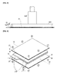
- FIG. 1 is a perspective view showing an electrical device 1 in which separators 30 are joined by the separator welding apparatus 100
- Figure 2 is an exploded perspective view showing an electrical device 1 in which separators are joined by the separator welding apparatus 100
- Figure 3 is a perspective view showing a state in which, by the welding apparatus 100, a positive electrode 10 is enclosed in a bag or a pouch by a pair of separators 30 to form a pouched electrode 50 with, on both ends thereof, being laminated with a negative electrode 20, respectively
- Figure 4 is a sectional view taken along line 4-4 shown Figure 3 ;
- the electrical device 1 represents a lithium ion secondary battery, a lithium polymer battery, a nickel hydrogen battery, a nickel cadmium battery.
- the power generating element 60 for charge/ discharge is sealed with an outer or exterior material 40.
- the power generating element 60 is configured by alternately laminating a pouched electrode 50 sandwiching a positive electrode 10 by a pair of separators 30 for welding and a negative electrode 20.
- the positive electrode 10 represents a first electrode, and is formed by bonding on both surfaces of a conductive, positive electrode collector 11, a positive active materials 12, as shown in FIG. 2 .
- a positive electrode terminal 11a for taking out the power is formed by extending a part of one end of the positive electrode collector 11.
- a plurality of positive electrode terminals 11a of the plurality of laminated positive electrodes 10 are fixed together by welding or adhesive.
- the material of the positive electrode current collector 11 of the positive electrode 10 is made of aluminum expanded metal, or aluminum mesh or aluminum punched metal.
- the material of the positive electrode active material 12 of the positive electrode 10 is composes of various oxides (lithium manganese oxide, such as LiMn2O4; manganese dioxide ; lithium nickel oxides such as LiNiO2; lithium cobalt oxide such as LiCoO2; lithium-containing nickel-cobalt oxide; amorphous pentoxide vanadium containing lithium) or chalcogen compound (titanium disulfide, molybdenum disulfide).
- a negative electrode 20 corresponds to a second electrode of different polarity to the first electrode (positive electrode 10), and as shown in FIG. 2 , is formed by bonding negative active material 22 on both surfaces of a negative electrode current collector 21 which is conductive.
- a negative electrode terminal 21a is formed by extending from a part of one end of the negative electrode collector 21 so as not overlap the positive electrode terminal 11a formed in the positive electrode 10.
- the longitudinal length of the negative electrode 20 is longer than the longitudinal length of the positive electrode 10. In the lateral length of the negative electrode 20 is of the same as that of the positive electrode 10.
- a plurality of negative electrode terminals 21a of the negative electrodes 20 stacked is secured together by adhesive or welding.
- carbon material for example, natural graphite, artificial graphite, carbon black, activated carbon, carbon fiber, coke, or organic precursor (phenolic resin, polyacrylonitrile, or cellulose) is heat-treated in an inert atmosphere and synthetic carbon is used.
- the separator 30 is provided between the positive and negative electrodes 10, 20 to electrically isolate the positive electrode 10 and the negative electrode 20 from each other. By holding an electrolyte solution between the positive electrode 10 and the negative electrode 20, the separator 30 ensures conductivity of the ion.
- the separator 30 is formed in a rectangular shape. The longitudinal length of the separator 30 is longer than the longitudinal length of the negative electrode 20 except the portion of the negative electrode terminal 21a.
- the separator 30, as shown in FIG. 4 is formed by laminating a hot-melt material 31 and a heat-resistant material 32.
- the heat-resistant material 32 has a higher melting temperature than that of the melt material 31.
- a pair of adjacent separators 30 is bonded with the associated melt material 32 faced to each other.
- the powder may be confined and sealed in the interior of the pair of the adjacent separators 30. That is, even if the electrical device 1 receives shocks or vibrations, it is possible to prevent scattering of the heat-resistant material 32 of the separator 30.
- the heat-resistant material 32 of the separator 30 and the positive electrode active material 12 of the positive electrode 10 are in contact with each other. Between the heat-resistant material 32 and the positive electrode active material 12, friction force is generated. Therefore, even if the electrical device 1 vibrates or receives shocks, the vibration of the positive electrode 10 may be suppressed with the positive electrode 10 bagged with the separator 30 in a pouched electrode 50. More specifically, be suppressing a positional deviation of the positive electrode 10 within the electrical device 1, damage of the electrical device 1 may be prevented, and an electrical property is maintained.
- the material of the melt material 31 of the separator 30 for example, use is made of a polypropylene.
- the molten material 31 is impregnated with a non-aqueous electrolyte solution prepared by dissolving an electrolyte in a non-aqueous solvent.
- a polymer for example, use is made to contain a polymer.
- a material of the heat-resistant material 32 of the separator 30 for example, use is made of a ceramic molded with a high temperature inorganic compounds. The ceramic is formed to be porous by binding ceramic particles of silica, alumina, zirconium oxide, titanium oxide with a binder.
- the material of the heat-resistant material 32 is not limited to ceramic. The alternative is acceptable as long as the melting temperature thereof may be higher than the melting member 31.
- the outer or exterior package 40 may be consisted, for example, of laminate sheets 41,42 with a metal plate inside and is sealed by covering both sides of the power generating element 60.
- a portion of the periphery of the laminate sheet 41 and 42 is made open, and the other periphery will be sealed by heat welding or the like.
- An electrolyte is injected from the portion that is open and the separator 30 or the like is impregnated with a liquid charge. While depressurizing the interior from the open portion of the laminate sheets 41, 42 to remove air, the open portion will also be heat-sealed to seal completely.
- the material for the laminate sheets 41, 42 for example, use is made of three different, laminated materials. Specifically, for the material of the heat-fusible resin of the first layer adjacent to the negative electrode 20, use is made from, for example, polyethylene (PE), ionomer, or ethylene vinyl acetate (EVA). As the metal foil of the second layer, for example, use is made of a Al foil or Ni foil. As the resin film of the third layer, for example, use is made of polyethylene terephthalate (PET) or nylon with rigidity.
- PET polyethylene terephthalate
- the electrical device 1 includes a power generating element 60.
- the power generating element 60 is formed by laminating a first electrode (positive electrode 10) and a second electrode (negative electrode 20) of polarity different from the first electrode (positive electrode 10) with a separator 30 interposed therebetween.
- the separator 30 includes a melt material 31 and a heat-resistant material 32 laminated on only one surface of the melt material 31 and having a melting point higher than the melt material 31. The adjacent separators 30 are joined together with the respective heat-resistant material 32 thereof facing each other.
- the heat-resistant material 32 may be sealed by confining the heat-resistant material 32 within the interior of the adjacent separators 30.
- the electrical device 1 vibrates or receives shocks, it is possible to prevent the heat-resistant material 32 of the separator 30 from being scattered. Therefore, the electric property of the electrical device may be maintained.
- the electrical device 1 may be configured such that, out of the first electrode (positive electrode 10) and the second electrode (negative electrode 20), the electrode with a relatively higher frictional force with the heat-resistant material 32 may be selected to be sandwiched by the adjacent separators 30 for welding or joining.
- the heat-resistant material 32 and the positive electrode active material 12 of the positive electrode 10 are in contact to each other to generate a friction force therebetween.
- the electrical device vibrates or receives shocks, it is possible to prevent the positive electrode 10 from being displaced within a pouched electrode 50 in which the positive electrode 10 is bagged or pouched by separators 30.
- the electrical device 1 by suppressing stack deviation of the positive electrode 10, the electrical device 1 may be protected from damage and the electric property thereof may be maintained.
- the heat-resistant material 32 may be configured to include a powder applied to the melt material 31 and subsequently dried.
- the powder when the heat-resistant material 32 is composed of easily to be scattered powder, the powder may be sealed by confining the powder within the interior of the separator 30. That is, even when the electrical device vibrates and receives shocks, within the electrical device 1, the heat-resistant material composed of powder may be effectively blocked from scattering by the melt material 31 of the separator 30.
- the powder may be formed of ceramics.
- the electric device 1 configured as described above, in particular, even when the heat-resistant material 32 is made of porous material which can be easily scattered as ceramics molded from inorganic compounds at a high temperature, the ceramics may be sealed to confine within the interior of the adjacent separators 30. That is, even when the electrical device vibrates and receives shocks, within the electrical device 1, the heat-resistant material composed of porous ceramics formed by binding particles and binder may be effectively blocked from scattering by the melt material 31 of the separator 30.
- FIG. 5 is a perspective view showing a separator welding apparatus 100 for joining the separators 30 of an electrical device
- FIG. 6 is a side view showing the vicinity of a vacuum suction conveyance drum 540 of a separator welding apparatus 100 that joins the separators 30 of an electrical device 1
- FIG. 7 is a side view showing the vicinity of the suction conveyor 310 of the separator welding apparatus 100 for separators 30 of an electrical device 1
- FIG. 8 is a side view showing the vicinity of a pouched electrode suction pad 810 of a separator welding apparatus 100 which joins separators 30 of an electrical device 1
- FIG. 9 is a perspective view showing the vicinity of a heating press member 710 of the separator welding apparatus 100 which joins separators 30 of an electrical device 1
- FIG. 10 is a section view along line 10-10 in FIG. 9 .
- separators 30 it is equally acceptable to join separators 30 together while conveying by pressurizing the separators 30 together by a heating press member 710 while heating, and to insert thereafter a positive electrode between a pair of the separators 30.
- a heating press member 710 while heating, and to insert thereafter a positive electrode between a pair of the separators 30.
- description is given with respect to such a configuration in which the positive electrode sandwiched by the separators 30 are joined together by heating press member 710 under heat and pressure while being conveyed.
- the positive electrode 10 is held by being wound into a roll around a positive electrode winding roller 210.
- the positive electrode winding roller 210 is formed in a cylindrical shape and rotates in a clockwise direction following the rotation of the suction conveyor 310.
- the positive electrode 10 is carried out from the positive electrode winding roller 210 conveyed in the direction of 640 toward a vacuum suction conveyance drum 540 described below through a conveyance roller 220.
- the suction conveyer 310 representative of a conveying apparatus consists of an endless belt and provided with a plurality of suction holes on the surface.
- a plurality of rotating rollers 320 is arranged on the inner circumferential surface of the suction conveyor 310.
- One of a plurality of the rotating rollers 20 is intended for a driving roller, and the others are driven rollers.
- the suction conveyors 310 caused to be rotated in a clockwise direction by the plurality of rotating rollers 320 are provided in two sets respectively on the conveyance downstream side and the conveyance upstream side of the positive electrode with respect to the vacuum suction conveyance drums 540, 640.
- the cutting members 410, 420 for cutting out the positive electrode 10 are disposed between two sets of suction conveyors 310 disposed upstream in the conveyance direction of the positive electrode 10 with respect to the vacuum suction conveyance drum 540, 640.
- the cutting member 410 is provided at the tip with a sharp and straight cutting blade and cuts one end of the positive electrode 10 that is continuous.
- the cutting member 420 is provided with a sharp and bent cutting blade at the tip, and cuts the other end of the positive electrode 10 immediately after being cut at that one end.
- the shape of the bent cutting blade of the cutting member 420 corresponds to the shape of the positive electrode terminal 11a.
- One separator 30 of the pair of separators 30 is held in a roll and wound around the separator winding roller 510.
- a melt or fused material 31 of the one separator 30 is in contact with a side of axis of the separator winding roller 510,
- the separator winding roller 510 is formed in a cylindrical shape and allowed to rotate in counterclockwise direction following the rotation of the vacuum suction conveyance drum 540 representing the conveying apparatus.
- the one separator 30 is conveyed with a constant tension posed and sandwiched between the pressure roller 520 and the nip roller 530, and is further caused to rotate in a counterclockwise in a state of being vacuum sucked around the vacuum suction conveyance drum 540.
- the vacuum suction conveyance drum 540 is formed in a cylindrical shape with a plurality of suction ports.
- the one separator 30 is cut out with a constant interval by a cutting member 430 disposed adjacent the vacuum suction conveyance drum 540 and having a sharp cutting blade at its tip.
- the other separator 30 of the pair separators 30 is held by winding into a roll around the separator winding roller 610.
- a melt material 31 of the other separator 30 is in contact with a side of axis of the separator winding roller 610,
- the separator winding roller 610 is formed in a cylindrical shape and allowed to rotate in clockwise direction following the rotation of the vacuum suction conveyance drum 640 representing the conveying apparatus.
- the other separator 30 is conveyed with a constant tension imposed and sandwiched between the pressure roller 620 and the nip roller 630, and is further caused to rotate in a clockwise in a state of being vacuum sucked around the vacuum suction conveyance drum 640.
- the vacuum suction conveyer drum 640 is formed in a cylindrical shape with a plurality of suction ports.
- the other separator 30 is cut out with a constant interval by a cutting member 440 disposed adjacent the vacuum suction conveyance drum 640 and having a sharp cutting blade at its tip.
- the one separator 30, the positive electrode 10, and the other separator 30 are conveyed in a laminated state such that the pair of the separators 30 sandwich the positive electrode 10 in a gap created between the vacuum suction conveyance drums 540, 640.
- the heating press member 710 is respectively disposed above and below both ends of the pair of separators 30 in the longitudinal direction thereof and is configured to sandwich the pair of the separators 30 and subsequently move up or down to separate from each other.
- the one separator 30, the positive electrode 10, and the other separator 30 are in a stacked state. However, they are shown separately from each other.
- the pair of separators 30 sandwiching the positive electrode 10 are joined or welded to form a pouched electrode 50.
- the pair of the separators 30 is disposed such that the respective heat-resistant member 32 comes to face each other.
- the heating press member 710 is made of stainless steel or copper, for example, and formed in a cuboid shape.
- the heating press member 710 is driven to move up and down by a drive unit not shown.
- the heating press member 910 will be heated by a heat wire or a heating bulb.
- a plurality of the heating press members 710 is disposed so as to sandwich both ends of the pair of the separators 30 in the longitudinal direction thereof from the vertical direction.
- the configuration shown by section in FIG. 10A corresponds that shown in perspective view in FIG. 9 .
- the one separator 30, the positive electrode 10, and the other separator 30 are in a stacked state. However, they are shown separately from each other.
- the pair of separators 30 may be welded. At this time, the pair of the separators 30 are heated and pressurized by the heating press member 710 to be joined.
- the heating press member 710 pressurized the pair of separators 30 clamping the positive electrode 10 while heating to join the paired separators 30.
- the welding process of such a pair of the separators 30 corresponds to a process of a so-called pouched electrode forming step, which is efficient in terms of productivity and cost.
- a bagged or pouched electrode suction pad 1010 corresponding to a conveying apparatus places a completed pouched electrode 50 temporarily on a mounting table 1050.
- the pouched electrode suction pad 1010 is plate-shaped and provided with a plurality of suction ports in the surface which is in contact with the pouched electrode 50.
- the pouched electrode suction pad 1010 is coupled to an end of a telescopic part 1020, which is telescopically extendable by power of the air compressor or the like, for example (not shown).
- the other end of the telescopic part 1020 is coupled to a plate-shaped support member 1030.
- the support member 1030 reciprocates along a pair of rails by a rotation motor (not shown), for example.
- the pouched electrode suction pad 1010 moves the pouched electrode 50 while sucking the same by the telescopic part 1020, support member 1030, and the pair of rails 1040, which has been conveyed by the suction conveyor 310 to place on the mounting table 850.
- a conveying apparatus which conveys or transports the separator 30 in a sucked state.
- the material of the melt material 31 of the separator 30 for example, use is made of a polypropylene, which is not scattered.
- a material of the heat-resistant material 32 of the separator 30 for example, use is made of a ceramic molded with high temperature inorganic compounds, which is easily scattered in powder.
- the vacuum suction conveyance drum 540, the suction conveyor 310, and the pouched electrode suction pad 810 is configured to suck the side of the melt material 31 of the separator 30, which is easily scattered, instead of the heat-resistant material 32 of the separator 30.
- the electrical device 1 thus configured, since the side of the melt material 31 on the separator 30, which is difficult to be scattered, is sucked for transportation, it is possible to prevent the heat-resistant material 32 of the separator 30 from being scattered within the separator welding apparatus 100.
- each of the conveying apparatuses, the vacuum suction conveyance drum 540, the suction conveyer 310, and the pouched electrode suction pad 810 transports the separate 30 while sucking the side of the melt material 31 on which the separator 30 will not be scattered.
- the suction force thereof may be maintained constant. Due to the constant suction force of the separator at each conveying apparatus, the feed rate or size of the separator is held constant. Further, since each conveying apparatus does not suck the side of the heat-resistant material on which scattering is expected, the heat-resistant material 32 is unlikely to flow into pieces. Thus, is not necessary to provide a cleaning mechanism to remove the scatter flied powder and the like in the periphery of each conveying apparatus.
- each conveying apparatus is configured not to suck the side of the heat-resistant material, which is easily scattered or peeled off, it is possible to prevent the heat-resistant material 32 from exfoliating from the melt material 31, or occurring suction marks, or generating touch marks.
- each conveying apparatus is configured not to suck the side of the heat-resistant material 32, which easily scatter flies so as to be prevented from being clogged with powder. Therefore, it is not necessary to install, clean or replace in a regular interval a filter or the like in each conveying apparatus for removal to the powder.
- a welding method of a separator of an electrical device 1, and a separator welding apparatus 100 that implements the welding method is intended, in a laminated body formed by alternately laminating a first electrode (positive electrode 10), a second electrode (negative electrode 20) of polarity different from the first electrode (positive electrode 10) with a separator interposed therebetween, to join adjacent separators 30.
- Use is thereby made of a separator 30 including a hot-melt material 31, and a heat resistant material 32 laminated on only one surface of the melt material 31 and having a higher melting point than the melt material.
- the separator 30 is conveyed with the side of the melt material 31 of the separator 30 being held, and the adjacent separators 30 are joined with the respective heat-resistant material 32 facing each other.
- a separator welding apparatus 100 since the side of the melt material 31, on which the separator 30 is less likely scattered is held for transportation, in the separator welding apparatus 100, it is possible to prevent the heat-resistant material 32 of the separator 30 from being scattered. Therefore, it is possible to keep clean inside the separator welding apparatus 100, and to maintain the electric property of the electrical device 1 whose separators are joined.
- each of the conveying apparatuses i.e., the vacuum suction conveying drum 540, the suction conveyor 310, and the pouched electrode suction pad 810, sucks the side of melt material 31, on which the separator 30 is unlikely to scatter flies while conveying.
- the suction force may be maintained constant.
- the feeding rate or size of the separator 30 may be held constant.
- each conveying device does not suck the side of heat-resistant material 32 which is easily scattered.
- each conveying apparatus does not suck the side of heat-resistant material 32 which is easily peeled off and scattered, the heat-resistant material 32 will be prevented from exfoliated from the melt material 31. Also, the suction marks may be prevented from occurring. In addition, contact or scratch marks may be prevented from being caused.
- each conveying apparatus does not suck the easily to be scattered heat-resistant material 32 side, the apparatus is less likely to be clogged with powder. It is not necessary to provide, replace for cleaning on a regular basis a filter and the like for powder removal in the conveying apparatus.
- a powder may be applied and then dried to the heat-resistant material 32 of the separator 30 to be bonded.
- ceramics may be used as the heat-resistant material 32 of the separators 30 to be joined.
- the heat-resistant material 32 is a porous material molded of inorganic compounds at a high temperature, it is possible to effectively prevent the heat-resistant material 32 of the separator 30 from scattering in the separator welding apparatus 100. Also, since each conveying apparatus does not suck ceramics, thus free from being clogged by the ceramics.
- FIG. 11 is a section view showing a part of an electrical device in a state in which a positive electrode 10 is laminated respectively on both surfaces of a pouched electrode 70 formed by a negative electrode 20 pouched by a pair of separators 30.
- Frictional force is generated between the heat-resistant material 32 of the separator 30 and the negative electrode active material 22 of the negative electrode 20 since they are in contact to each other. Therefore, even when the electrical device vibrates or receives shocks, it is possible to suppress displacement of the negative electrode 20 within the pouched electrode 50 in which the negative electrode 20 is pouched by separators 30. In other words, in the electrical device 1, by suppressing the stack deviation of the negative electrode 20, damage on the electrical device may be prevented, and the electrical property may be secured.
- the electrical device pertaining to the second embodiment described above is effective when the friction force generated between the melt material 32 and the negative electrode active material 22 of the negative electrode 20 is greater than the frictional force generated between the heat-resistant material 32 and the positive electrode active material 12.
- the separator 30 is conveyed with the side of the melt material 31 of the separator 30 sucked by the conveying apparatuses (vacuum suction conveyance drum 540, suction conveyer 310, and the pouched electrode suction pad 810).
- the configuration is not limited thereto.
- the separator 30 is transported while clamping the side of the melt material 31 of the separator 30, or when the separator 30 is transported with the side of the melt material 31 of the separator mounted by the conveying apparatus, it is possible to seal the heat resistant material 32 within the interior of the adjacent separators 30.
- the configuration of bagging or pouched structure in which the positive electrode 10 is pouched by a pair of separators 30 is not limited thereto.
- a positive electrode 20 may be pouched by a pair of separators 30 by way of the separator welding apparatus 100.
- This configuration is effective in a case in which the frictional force generated between the heat-resistant material 32 and the negative electrode active material 22 of the negative electrode 20 is greater than the frictional force generated between the heat-resistant material 20 and the positive electrode active material 12 of the positive electrode 10.
Landscapes
- Chemical & Material Sciences (AREA)
- Chemical Kinetics & Catalysis (AREA)
- Electrochemistry (AREA)
- General Chemical & Material Sciences (AREA)
- Engineering & Computer Science (AREA)
- Manufacturing & Machinery (AREA)
- Inorganic Chemistry (AREA)
- Mechanical Engineering (AREA)
- Cell Separators (AREA)
- Secondary Cells (AREA)
- Laminated Bodies (AREA)
Abstract
Description
- The present invention relates to an electrical device, a welding apparatus for a separator of the electrical device and to a cutting method thereof.
- Conventionally, in an electrical device such as a secondary battery, a power generating element for performing charging and discharging operations is sealed in an outer or exterior package. The power generating element is formed by stacking or laminating a separator and electrodes. The separator easily shrinks when heated. When the separator shrinks, electrical short circuit occurs locally. This would reduce the output of the electrical device.
- Thus, by using, as a counter measure, a separator which is formed by laminating on a heat-resistant layer of heat-resistant material a hot-melt layer having a melting point lower than the melting point of the heat-resistant layer, the separator is prevented from shrinkage or contracting even if the separator is heated. The hot-melt layers of the laminated battery are fixed together by thermal welding (see
Patent Document 1, for example). - Incidentally, a technique is disclosed as a laminating device of an electrode and a separator, in which first and second separators are drawn out in response to a rotation of a suction drum, and the electrode is bagged or pouched by the separators while the suction drum rotates once (see Patent Document 2). Further, another technique is disclosed in which a periphery of an electrode plate is enclosed by welding of a continuous separator so as to prevent the position of the electrode plate from being deviated (for example, see Patent Document 3).
-
- Patent Document 1: Japanese Patent Application Publication No.
2011-210524A - Patent Document 2: Japanese Patent Application Publication No.
2011-003381A - Patent Document 3: Japanese Patent Application Publication No.
2009-009919A - However, as shown in FIGS. 14 and 15 in the
Patent Document 1 identified above, the heat-resistant layers on the outermost surface at both ends of a laminated body are respectively exposed. Also, on both end portions of each separator, the heat-resistant layer is exposed. - In such a state, there is a possibility that when the stacked battery receives a shock or undergoes vibration, the heat-resistant material of the separator may be scattered, which would reduce the electrical characteristics. In the separator shown in
FIG. 3 ofPatent Document 1, since a hot-melt layer is disposed on both surfaces of the heat-resistant layer, the heat-resistant material is not scattered. However, the layer thickness of the separator becomes thicker. - Further, in any of the Patent Documents 2 and 3, when transporting or conveying the separator formed by laminating the heat-resistant material and the hot-melt material, no specific consideration is given so as block the otherwise easy to be scattered heat-resistant material from being scattered easily.
- In this configuration, when using a separator which is formed by laminating the heat-resistant material and the melt material, there is a possibility that the heat-resistant material of the separator may be scattered in the separator welding apparatus.
- The present invention has been made in order to solve the above problem, and aims to provide an electrical device which can prevent scattering of the heat-resistant material of the separator when receiving shocks or vibrations.
- Further, the present invention has been proposed in order to solve the above problem, and aims to provide a welding or bonding apparatus of a separator of an electrical device and a welding method thereof, in which the heat-resistant material of the separator is prevented from being scattered.
- In order to achieve the object described above, an electrical device pertaining to the present invention includes an electricity or power generating element. The power generating element is formed by laminating a first electrode and a second electrode of polarity different from the first electrode with a separator interposed therebetween. The separator includes a melt material and a heat-resistant material laminated on only one surface of the melt material and having a melting point higher than the melt material. The adjacent separators are welded with the heat-resistant material layers facing each other.
- Further, the electrical device pertaining to the present invention which achieves the object described above includes a power generating element. The power generating element is formed by laminating a first electrode and a second electrode whose polarity is different from the first electrode with a separator interposed therebetween. The separator includes a melt material and a heat-resistant material laminated on a surface of the melt material and having a melting point higher than the melt material. The separator is conveyed with the side of the melt material being held by a conveying apparatus, and the adjacent separators are joined together with the respective heat-resistant material thereof facing each other.
- Further, the separator welding apparatus pertaining to the present invention which achieves the object described above relates to a welding apparatus which laminates a first electrode, a second electrode of polarity different from the first electrode, and a separator alternately, and joining or welding adjacent separators together. A separator is used in which a melt material and a heat-resistant material laminated on only one surface of the melt material and having a melting point higher than the melt material. Here, the separator is conveyed with the side of the melt material being held by a conveying apparatus, and the adjacent separators are joined together with the respective heat-resistant material thereof facing each other.
- Further, the separator welding method pertaining to the present invention which achieves the object described above relates to a welding method which laminates a first electrode, a second electrode of polarity different from the first electrode, and a separator alternately, and joining or welding adjacent separators together. A separator is used in which a melt material and a heat-resistant material laminated on only one surface of the melt material and having a melting point higher than the melt material. Here, the separator is conveyed with the side of the melt material being held by a conveying apparatus, and the adjacent separators are joined together with the respective heat-resistant material thereof facing each other.
-
-
Figure 1 is a perspective view showing an electrical device pertaining to a first embodiment; -
Figure 2 is an exploded perspective view showing an electrical device pertaining to the first embodiment; -
Figure 3 is a perspective view showing a state in which, a positive electrode is enclosed in a bag or pouch by a pair of separators to form a pouched electrode, and, on both surfaces thereof, being laminated respectively with a negative electrode; -
Figure 4 is a sectional view pertaining to the first embodiment taken along line 4-4 ofFigure 3 ; -
Figure 5 is a perspective view showing a separator welding apparatus for joining the separators of the electrical device pertaining to the first embodiment; -
Figure 6 is a side view showing the vicinity of a vacuum suction conveyance drum of a separator welding apparatus that joins the separators of an electrical device pertaining to the first embodiment; -
Figure 7 is a side view showing the vicinity of a suction conveyor of the separator welding apparatus of separators of an electrical device pertaining to the first embodiment; -
Figure 8 is a side view showing the vicinity of a pouched electrode suction pad of a separator welding apparatus which joins separators of an electrical device pertaining to the first embodiment; -
Figure 9 is a perspective view showing the vicinity of a heating press member of the separator welding apparatus which joins separators of an electrical device pertaining to the first embodiment; -
Figure 10 is a section view along line 10-10 inFIG. 9 pertaining to the first embodiment; and -
Figure 11 is a section view of part of an electrical device in a state in which an electrode is pouched by a pair of separators to form a pouched electrode and a positive electrode is laminated respectively on both surfaces of the pouched electrode. - Below, with reference to accompanying drawings, description is given of an embodiment of the present invention. The same reference numerals are given to the same elements, and duplicate description will be omitted in the description of the drawings. The proportion and size of each member in the drawings may be different from the proportion and the size of the actual one, and exaggerated for convenience of explanation.
- First, description is given of a structure of an
electrical device 1 in whichseparators 30 are welded or joined by aseparator welding apparatus 100 pertaining to the first embodiment, with reference toFIGS. 1 to 4 . -
FIG. 1 is a perspective view showing anelectrical device 1 in whichseparators 30 are joined by theseparator welding apparatus 100;
Figure 2 is an exploded perspective view showing anelectrical device 1 in which separators are joined by theseparator welding apparatus 100; and
Figure 3 is a perspective view showing a state in which, by thewelding apparatus 100, apositive electrode 10 is enclosed in a bag or a pouch by a pair ofseparators 30 to form apouched electrode 50 with, on both ends thereof, being laminated with anegative electrode 20, respectively; and
Figure 4 is a sectional view taken along line 4-4 shownFigure 3 ; - As shown in
Figure 1 , for example, theelectrical device 1 represents a lithium ion secondary battery, a lithium polymer battery, a nickel hydrogen battery, a nickel cadmium battery.
A shown inFigure 2 , in theelectrical device 1, thepower generating element 60 for charge/ discharge is sealed with an outer orexterior material 40. Thepower generating element 60 is configured by alternately laminating apouched electrode 50 sandwiching apositive electrode 10 by a pair ofseparators 30 for welding and anegative electrode 20. - The
positive electrode 10 represents a first electrode, and is formed by bonding on both surfaces of a conductive,positive electrode collector 11, a positiveactive materials 12, as shown inFIG. 2 . Apositive electrode terminal 11a for taking out the power is formed by extending a part of one end of thepositive electrode collector 11. A plurality ofpositive electrode terminals 11a of the plurality of laminatedpositive electrodes 10 are fixed together by welding or adhesive. - The material of the positive electrode
current collector 11 of thepositive electrode 10, for example, is made of aluminum expanded metal, or aluminum mesh or aluminum punched metal. When theelectrical device 1 is a lithium ion secondary battery, the material of the positive electrodeactive material 12 of thepositive electrode 10 is composes of various oxides (lithium manganese oxide, such as LiMn2O4; manganese dioxide ; lithium nickel oxides such as LiNiO2; lithium cobalt oxide such as LiCoO2; lithium-containing nickel-cobalt oxide; amorphous pentoxide vanadium containing lithium) or chalcogen compound (titanium disulfide, molybdenum disulfide). - A
negative electrode 20 corresponds to a second electrode of different polarity to the first electrode (positive electrode 10), and as shown inFIG. 2 , is formed by bonding negativeactive material 22 on both surfaces of a negative electrodecurrent collector 21 which is conductive. Anegative electrode terminal 21a is formed by extending from a part of one end of thenegative electrode collector 21 so as not overlap thepositive electrode terminal 11a formed in thepositive electrode 10. The longitudinal length of thenegative electrode 20 is longer than the longitudinal length of thepositive electrode 10. In the lateral length of thenegative electrode 20 is of the same as that of thepositive electrode 10. A plurality ofnegative electrode terminals 21a of thenegative electrodes 20 stacked is secured together by adhesive or welding. - The material of the negative electrode
current collector 21 of thenegative electrode 20, for example, is made from a copper expanded metal, copper mesh, or copper punched metal.
As the material of the negative electrodeactive material 22 of thenegative electrode 20, when theelectrical device 1 is a lithium ion secondary battery, and use is made of a carbon material that adsorbs and releases lithium ion. As such carbon material, for example, natural graphite, artificial graphite, carbon black, activated carbon, carbon fiber, coke, or organic precursor (phenolic resin, polyacrylonitrile, or cellulose) is heat-treated in an inert atmosphere and synthetic carbon is used. - As shown in
FIG 2 , theseparator 30 is provided between the positive andnegative electrodes positive electrode 10 and thenegative electrode 20 from each other. By holding an electrolyte solution between thepositive electrode 10 and thenegative electrode 20, theseparator 30 ensures conductivity of the ion. Theseparator 30 is formed in a rectangular shape. The longitudinal length of theseparator 30 is longer than the longitudinal length of thenegative electrode 20 except the portion of thenegative electrode terminal 21a. - The
separator 30, as shown inFIG. 4 , is formed by laminating a hot-melt material 31 and a heat-resistant material 32. The heat-resistant material 32 has a higher melting temperature than that of themelt material 31. A pair ofadjacent separators 30 is bonded with the associatedmelt material 32 faced to each other. Thus, for example, even when the heat-resistant material 32 is powder which may easily scatter after being applied to themelt material 31 and subsequently dried, the powder may be confined and sealed in the interior of the pair of theadjacent separators 30. That is, even if theelectrical device 1 receives shocks or vibrations, it is possible to prevent scattering of the heat-resistant material 32 of theseparator 30. - Here, the heat-
resistant material 32 of theseparator 30 and the positive electrodeactive material 12 of thepositive electrode 10 are in contact with each other. Between the heat-resistant material 32 and the positive electrodeactive material 12, friction force is generated. Therefore, even if theelectrical device 1 vibrates or receives shocks, the vibration of thepositive electrode 10 may be suppressed with thepositive electrode 10 bagged with theseparator 30 in a pouchedelectrode 50. More specifically, be suppressing a positional deviation of thepositive electrode 10 within theelectrical device 1, damage of theelectrical device 1 may be prevented, and an electrical property is maintained. - As the material of the
melt material 31 of theseparator 30, for example, use is made of a polypropylene. Themolten material 31 is impregnated with a non-aqueous electrolyte solution prepared by dissolving an electrolyte in a non-aqueous solvent. In order to retain the non-aqueous electrolytic solution, use is made to contain a polymer. As a material of the heat-resistant material 32 of theseparator 30, for example, use is made of a ceramic molded with a high temperature inorganic compounds. The ceramic is formed to be porous by binding ceramic particles of silica, alumina, zirconium oxide, titanium oxide with a binder. The material of the heat-resistant material 32 is not limited to ceramic. The alternative is acceptable as long as the melting temperature thereof may be higher than the meltingmember 31. - As shown in
FIG 2 , the outer orexterior package 40 may be consisted, for example, oflaminate sheets power generating element 60. When sealing thepower generating element 60 with thelaminate sheets laminate sheet separator 30 or the like is impregnated with a liquid charge. While depressurizing the interior from the open portion of thelaminate sheets - As the material for the
laminate sheets negative electrode 20, use is made from, for example, polyethylene (PE), ionomer, or ethylene vinyl acetate (EVA). As the metal foil of the second layer, for example, use is made of a Al foil or Ni foil. As the resin film of the third layer, for example, use is made of polyethylene terephthalate (PET) or nylon with rigidity. - According to an
electrical device 1 in which separators 30 are welded together by aseparator welding apparatus 100 pertaining to the present embodiment described above, the following effects may be obtained. - The
electrical device 1 includes apower generating element 60. Thepower generating element 60 is formed by laminating a first electrode (positive electrode 10) and a second electrode (negative electrode 20) of polarity different from the first electrode (positive electrode 10) with aseparator 30 interposed therebetween. Theseparator 30 includes amelt material 31 and a heat-resistant material 32 laminated on only one surface of themelt material 31 and having a melting point higher than themelt material 31. Theadjacent separators 30 are joined together with the respective heat-resistant material 32 thereof facing each other. - According to the
electrical device 1 thus configured, the heat-resistant material 32 may be sealed by confining the heat-resistant material 32 within the interior of theadjacent separators 30. Thus, even when theelectrical device 1 vibrates or receives shocks, it is possible to prevent the heat-resistant material 32 of theseparator 30 from being scattered. Therefore, the electric property of the electrical device may be maintained. - Further, according to the
electrical device 1, it may be configured such that, out of the first electrode (positive electrode 10) and the second electrode (negative electrode 20), the electrode with a relatively higher frictional force with the heat-resistant material 32 may be selected to be sandwiched by theadjacent separators 30 for welding or joining. - According to the electrical device thus configured, for example, the heat-
resistant material 32 and the positive electrodeactive material 12 of thepositive electrode 10 are in contact to each other to generate a friction force therebetween. Thus, even when the electrical device vibrates or receives shocks, it is possible to prevent thepositive electrode 10 from being displaced within a pouchedelectrode 50 in which thepositive electrode 10 is bagged or pouched byseparators 30. In other words, in theelectrical device 1, by suppressing stack deviation of thepositive electrode 10, theelectrical device 1 may be protected from damage and the electric property thereof may be maintained. - Further, according to the
electrical device 1, the heat-resistant material 32 may be configured to include a powder applied to themelt material 31 and subsequently dried. - According to the
electric device 1 configured as described above, in particular, when the heat-resistant material 32 is composed of easily to be scattered powder, the powder may be sealed by confining the powder within the interior of theseparator 30. That is, even when the electrical device vibrates and receives shocks, within theelectrical device 1, the heat-resistant material composed of powder may be effectively blocked from scattering by themelt material 31 of theseparator 30. - In addition, according to the
electrical device 1, the powder may be formed of ceramics. - According to the
electric device 1 configured as described above, in particular, even when the heat-resistant material 32 is made of porous material which can be easily scattered as ceramics molded from inorganic compounds at a high temperature, the ceramics may be sealed to confine within the interior of theadjacent separators 30. That is, even when the electrical device vibrates and receives shocks, within theelectrical device 1, the heat-resistant material composed of porous ceramics formed by binding particles and binder may be effectively blocked from scattering by themelt material 31 of theseparator 30. - Now, description is give of a welding method for joining
separators 30 together of anelectrical device 1, and of aseparator welding apparatus 100 implementing the welding method, with reference toFIGS. 5 to 10 . -
FIG. 5 is a perspective view showing aseparator welding apparatus 100 for joining theseparators 30 of an electrical device;
FIG. 6 is a side view showing the vicinity of a vacuumsuction conveyance drum 540 of aseparator welding apparatus 100 that joins theseparators 30 of anelectrical device 1;
FIG. 7 is a side view showing the vicinity of thesuction conveyor 310 of theseparator welding apparatus 100 forseparators 30 of anelectrical device 1;
FIG. 8 is a side view showing the vicinity of a pouchedelectrode suction pad 810 of aseparator welding apparatus 100 which joinsseparators 30 of anelectrical device 1;
FIG. 9 is a perspective view showing the vicinity of aheating press member 710 of theseparator welding apparatus 100 which joinsseparators 30 of anelectrical device 1; and
FIG. 10 is a section view along line 10-10 inFIG. 9 . - Here, it is equally acceptable to join
separators 30 together while conveying by pressurizing theseparators 30 together by aheating press member 710 while heating, and to insert thereafter a positive electrode between a pair of theseparators 30. However, in view of productivity and quality, description is given with respect to such a configuration in which the positive electrode sandwiched by theseparators 30 are joined together by heatingpress member 710 under heat and pressure while being conveyed. - As shown in
FIG. 5 , in theseparator welding apparatus 100, thepositive electrode 10 is held by being wound into a roll around a positiveelectrode winding roller 210. The positiveelectrode winding roller 210 is formed in a cylindrical shape and rotates in a clockwise direction following the rotation of thesuction conveyor 310. Thepositive electrode 10 is carried out from the positiveelectrode winding roller 210 conveyed in the direction of 640 toward a vacuumsuction conveyance drum 540 described below through aconveyance roller 220. - The
suction conveyer 310 representative of a conveying apparatus consists of an endless belt and provided with a plurality of suction holes on the surface. On the inner circumferential surface of thesuction conveyor 310, a plurality ofrotating rollers 320 is arranged. One of a plurality of therotating rollers 20 is intended for a driving roller, and the others are driven rollers. Thesuction conveyors 310 caused to be rotated in a clockwise direction by the plurality ofrotating rollers 320 are provided in two sets respectively on the conveyance downstream side and the conveyance upstream side of the positive electrode with respect to the vacuum suction conveyance drums 540, 640. - The cutting
members positive electrode 10 are disposed between two sets ofsuction conveyors 310 disposed upstream in the conveyance direction of thepositive electrode 10 with respect to the vacuumsuction conveyance drum member 410 is provided at the tip with a sharp and straight cutting blade and cuts one end of thepositive electrode 10 that is continuous. The cuttingmember 420 is provided with a sharp and bent cutting blade at the tip, and cuts the other end of thepositive electrode 10 immediately after being cut at that one end. The shape of the bent cutting blade of the cuttingmember 420 corresponds to the shape of thepositive electrode terminal 11a. - One
separator 30 of the pair ofseparators 30 is held in a roll and wound around theseparator winding roller 510. A melt or fusedmaterial 31 of the oneseparator 30 is in contact with a side of axis of theseparator winding roller 510, Theseparator winding roller 510 is formed in a cylindrical shape and allowed to rotate in counterclockwise direction following the rotation of the vacuumsuction conveyance drum 540 representing the conveying apparatus. The oneseparator 30 is conveyed with a constant tension posed and sandwiched between thepressure roller 520 and thenip roller 530, and is further caused to rotate in a counterclockwise in a state of being vacuum sucked around the vacuumsuction conveyance drum 540. The vacuumsuction conveyance drum 540 is formed in a cylindrical shape with a plurality of suction ports. The oneseparator 30 is cut out with a constant interval by a cuttingmember 430 disposed adjacent the vacuumsuction conveyance drum 540 and having a sharp cutting blade at its tip. - Similarly, the
other separator 30 of thepair separators 30 is held by winding into a roll around theseparator winding roller 610. Amelt material 31 of theother separator 30 is in contact with a side of axis of theseparator winding roller 610, Theseparator winding roller 610 is formed in a cylindrical shape and allowed to rotate in clockwise direction following the rotation of the vacuumsuction conveyance drum 640 representing the conveying apparatus. Theother separator 30 is conveyed with a constant tension imposed and sandwiched between thepressure roller 620 and thenip roller 630, and is further caused to rotate in a clockwise in a state of being vacuum sucked around the vacuumsuction conveyance drum 640. The vacuumsuction conveyer drum 640 is formed in a cylindrical shape with a plurality of suction ports. Theother separator 30 is cut out with a constant interval by a cuttingmember 440 disposed adjacent the vacuumsuction conveyance drum 640 and having a sharp cutting blade at its tip. - The one
separator 30, thepositive electrode 10, and theother separator 30 are conveyed in a laminated state such that the pair of theseparators 30 sandwich thepositive electrode 10 in a gap created between the vacuum suction conveyance drums 540, 640. - As shown in
FIG. 9 , theheating press member 710 is respectively disposed above and below both ends of the pair ofseparators 30 in the longitudinal direction thereof and is configured to sandwich the pair of theseparators 30 and subsequently move up or down to separate from each other. Note that, inFIG. 9 , actually, the oneseparator 30, thepositive electrode 10, and theother separator 30 are in a stacked state. However, they are shown separately from each other. The pair ofseparators 30 sandwiching thepositive electrode 10 are joined or welded to form a pouchedelectrode 50. The pair of theseparators 30 is disposed such that the respective heat-resistant member 32 comes to face each other. Theheating press member 710 is made of stainless steel or copper, for example, and formed in a cuboid shape. Theheating press member 710 is driven to move up and down by a drive unit not shown. The heating press member 910 will be heated by a heat wire or a heating bulb. - As shown in
FIG. 10A , a plurality of theheating press members 710 is disposed so as to sandwich both ends of the pair of theseparators 30 in the longitudinal direction thereof from the vertical direction. The configuration shown by section inFIG. 10A corresponds that shown in perspective view inFIG. 9 . Note that, inFIG. 10A , actually, the oneseparator 30, thepositive electrode 10, and theother separator 30 are in a stacked state. However, they are shown separately from each other. - As shown in
FIG. 10B , by driving a plurality ofheating press members 710 in the direction shown by P1 in the figure from both directions in the vertical direction so as to clamp or sandwich both ends in the longitudinal direction of theseparators 30, the pair ofseparators 30 may be welded. At this time, the pair of theseparators 30 are heated and pressurized by theheating press member 710 to be joined. - As shown in
FIG. 10C , by driving a plurality ofheating press members 710 in the direction shown by P2 in the figure from both directions in the vertical direction so as to be separated from the joined pair of theseparators 30. In the separator welding method described above with reference toFIGS. 11 and10 , theheating press member 710 pressurized the pair ofseparators 30 clamping thepositive electrode 10 while heating to join the pairedseparators 30. The welding process of such a pair of theseparators 30 corresponds to a process of a so-called pouched electrode forming step, which is efficient in terms of productivity and cost. - A bagged or pouched electrode suction pad 1010 corresponding to a conveying apparatus places a completed
pouched electrode 50 temporarily on a mounting table 1050. The pouched electrode suction pad 1010 is plate-shaped and provided with a plurality of suction ports in the surface which is in contact with the pouchedelectrode 50. The pouched electrode suction pad 1010 is coupled to an end of a telescopic part 1020, which is telescopically extendable by power of the air compressor or the like, for example (not shown). The other end of the telescopic part 1020 is coupled to a plate-shaped support member 1030. The support member 1030 reciprocates along a pair of rails by a rotation motor (not shown), for example. As described, the pouched electrode suction pad 1010 moves the pouchedelectrode 50 while sucking the same by the telescopic part 1020, support member 1030, and the pair of rails 1040, which has been conveyed by thesuction conveyor 310 to place on the mounting table 850. - The vacuum
suction conveyance drum 540, thesuction conveyor 310, and the pouchedelectrode suction pad 810, shown inFIGS. 6 yo8, respectively, collectively correspond to a conveying apparatus which conveys or transports theseparator 30 in a sucked state. Here, as the material of themelt material 31 of theseparator 30, for example, use is made of a polypropylene, which is not scattered. On the other hand, as a material of the heat-resistant material 32 of theseparator 30, for example, use is made of a ceramic molded with high temperature inorganic compounds, which is easily scattered in powder. Thus, the vacuumsuction conveyance drum 540, thesuction conveyor 310, and the pouchedelectrode suction pad 810 is configured to suck the side of themelt material 31 of theseparator 30, which is easily scattered, instead of the heat-resistant material 32 of theseparator 30. According to theelectrical device 1 thus configured, since the side of themelt material 31 on theseparator 30, which is difficult to be scattered, is sucked for transportation, it is possible to prevent the heat-resistant material 32 of theseparator 30 from being scattered within theseparator welding apparatus 100. - Further, each of the conveying apparatuses, the vacuum
suction conveyance drum 540, thesuction conveyer 310, and the pouchedelectrode suction pad 810 transports the separate 30 while sucking the side of themelt material 31 on which theseparator 30 will not be scattered. Thus the suction force thereof may be maintained constant. Due to the constant suction force of the separator at each conveying apparatus, the feed rate or size of the separator is held constant. Further, since each conveying apparatus does not suck the side of the heat-resistant material on which scattering is expected, the heat-resistant material 32 is unlikely to flow into pieces. Thus, is not necessary to provide a cleaning mechanism to remove the scatter flied powder and the like in the periphery of each conveying apparatus. Therefore, the structure of theseparator welding apparatus 100 may be made compact and cost thereof may be reduced. In addition, each conveying apparatus is configured not to suck the side of the heat-resistant material, which is easily scattered or peeled off, it is possible to prevent the heat-resistant material 32 from exfoliating from themelt material 31, or occurring suction marks, or generating touch marks. Furthermore, each conveying apparatus is configured not to suck the side of the heat-resistant material 32, which easily scatter flies so as to be prevented from being clogged with powder. Therefore, it is not necessary to install, clean or replace in a regular interval a filter or the like in each conveying apparatus for removal to the powder. - According to the welding method of separators together of an
electrical device 1 described above, and aseparator welding apparatus 100 carrying out the welding method, the following effects may be obtained. - A welding method of a separator of an
electrical device 1, and aseparator welding apparatus 100 that implements the welding method is intended, in a laminated body formed by alternately laminating a first electrode (positive electrode 10), a second electrode (negative electrode 20) of polarity different from the first electrode (positive electrode 10) with a separator interposed therebetween, to joinadjacent separators 30. Use is thereby made of aseparator 30 including a hot-melt material 31, and a heatresistant material 32 laminated on only one surface of themelt material 31 and having a higher melting point than the melt material. Here, theseparator 30 is conveyed with the side of themelt material 31 of theseparator 30 being held, and theadjacent separators 30 are joined with the respective heat-resistant material 32 facing each other. - According to the thus configured welding method of separators of an
electrical device 1, aseparator welding apparatus 100, since the side of themelt material 31, on which theseparator 30 is less likely scattered is held for transportation, in theseparator welding apparatus 100, it is possible to prevent the heat-resistant material 32 of theseparator 30 from being scattered. Therefore, it is possible to keep clean inside theseparator welding apparatus 100, and to maintain the electric property of theelectrical device 1 whose separators are joined. - In addition, each of the conveying apparatuses, i.e., the vacuum
suction conveying drum 540, thesuction conveyor 310, and the pouchedelectrode suction pad 810, sucks the side ofmelt material 31, on which theseparator 30 is unlikely to scatter flies while conveying. Thus, the suction force may be maintained constant. When the suction force of theseparator 30 is held constant by each conveying apparatus, the feeding rate or size of theseparator 30 may be held constant. - Further, each conveying device does not suck the side of heat-
resistant material 32 which is easily scattered. Thus, it is not necessary to provide mechanism for removing and cleaning the scattered powder and the like scattered in the periphery of the conveying apparatus. Therefore, it is possible to miniaturize the arrangement of aseparator welding apparatus 100 while reducing the associated cost. - Furthermore, since each conveying apparatus does not suck the side of heat-
resistant material 32 which is easily peeled off and scattered, the heat-resistant material 32 will be prevented from exfoliated from themelt material 31. Also, the suction marks may be prevented from occurring. In addition, contact or scratch marks may be prevented from being caused. - Furthermore, since each conveying apparatus does not suck the easily to be scattered heat-
resistant material 32 side, the apparatus is less likely to be clogged with powder. It is not necessary to provide, replace for cleaning on a regular basis a filter and the like for powder removal in the conveying apparatus. - Further, when joining the
separators 30 of theelectric device 1, a powder may be applied and then dried to the heat-resistant material 32 of theseparator 30 to be bonded. - With this configuration, even when the heat-
resistant material 32 is formed in powder and easily scattered, it is possible to effectively prevent the heat-resistant material 32 of theseparator 30 from being scattered. Further, since each conveying apparatus does not suck powder, it is not suffered from clogging. - Further, when welding the
separators 30 of anelectrical device 1, ceramics may be used as the heat-resistant material 32 of theseparators 30 to be joined. - With this configuration, in particular, when the heat-
resistant material 32 is a porous material molded of inorganic compounds at a high temperature, it is possible to effectively prevent the heat-resistant material 32 of theseparator 30 from scattering in theseparator welding apparatus 100. Also, since each conveying apparatus does not suck ceramics, thus free from being clogged by the ceramics. - Description is now given of an electrical device pertaining to a second embodiment with reference to
FIG. 11 . - In the second embodiment, with respect to the similar structure as the first embodiment, the same reference numeral is used and the description thereof is omitted.
-
FIG. 11 is a section view showing a part of an electrical device in a state in which apositive electrode 10 is laminated respectively on both surfaces of a pouchedelectrode 70 formed by anegative electrode 20 pouched by a pair ofseparators 30. - Frictional force is generated between the heat-
resistant material 32 of theseparator 30 and the negative electrodeactive material 22 of thenegative electrode 20 since they are in contact to each other. Therefore, even when the electrical device vibrates or receives shocks, it is possible to suppress displacement of thenegative electrode 20 within the pouchedelectrode 50 in which thenegative electrode 20 is pouched byseparators 30. In other words, in theelectrical device 1, by suppressing the stack deviation of thenegative electrode 20, damage on the electrical device may be prevented, and the electrical property may be secured. - The electrical device pertaining to the second embodiment described above is effective when the friction force generated between the
melt material 32 and the negative electrodeactive material 22 of thenegative electrode 20 is greater than the frictional force generated between the heat-resistant material 32 and the positive electrodeactive material 12. - In addition, the present invention is capable of various modifications on the basis of the configuration described in CLAIMS, which will be included within the scope of the present invention and their equivalents.
- In the first embodiment, as an example, description is given of a conveying apparatus in which the
separator 30 is conveyed with the side of themelt material 31 of theseparator 30 sucked by the conveying apparatuses (vacuumsuction conveyance drum 540,suction conveyer 310, and the pouched electrode suction pad 810). However, the configuration is not limited thereto. For example, even when theseparator 30 is transported while clamping the side of themelt material 31 of theseparator 30, or when theseparator 30 is transported with the side of themelt material 31 of the separator mounted by the conveying apparatus, it is possible to seal the heatresistant material 32 within the interior of theadjacent separators 30. - Further, in the embodiment, as an example, description is given of the configuration of bagging or pouched structure in which the
positive electrode 10 is pouched by a pair ofseparators 30. However, the configuration is not limited thereto. For example, it may be configured that apositive electrode 20 may be pouched by a pair ofseparators 30 by way of theseparator welding apparatus 100. This configuration is effective in a case in which the frictional force generated between the heat-resistant material 32 and the negative electrodeactive material 22 of thenegative electrode 20 is greater than the frictional force generated between the heat-resistant material 20 and the positive electrodeactive material 12 of thepositive electrode 10. - This application is filed based on a Japanese Patent Application No.
2012-286988 filed December 28, 2012 2012-286993 filed December 28, 2012 -
- 1
- electrical device
- 10
- positive electrode (first electrode),
- 11a
- positive electrode terminal
- 12
- positive electrode active material
- 20
- negative electrode (second electrode),
- 21
- negative electrode collector,
- 21a
- negative electrode terminal,
- 22
- negative electrode active material,
- 30
- separator,
- 31
- melt or fused material,
- 32
- heat-resistant material,
- 40
- outer or exterior package,
- 41,42
- laminate sheet,
- 50,70
- bagged or pouched electrode,
- 60
- power generating element,
- 100
- separator welding or joining apparatus,
- 210
- positive electrode winding roller,
- 220
- conveyance roller,
- 310
- suction conveyer,
- 410,420,430,440
- cutting member,
- 510, 610
- separator winding roller,
- 520,620
- pressure roller,
- 530,630
- nip roller,
- 540, 640
- vacuum suction conveyor drum (conveying apparatus),
- 710
- heating press member,
- 810
- pouched electrode suction pad (conveying apparatus),
- 820
- telescopic part,
- 830
- support member,
- 840
- rail, and
- 850
- mounting table.
Claims (10)
- An electrical device, comprising:a power generating element formed by laminating a first electrode, a second electrode of polarity different from the first electrode with a separator interposed therebetween, wherein the separator includes a melt material and a heat-resistant material laminated on only one surface of the melt material and having a melting point higher than the melt material, and wherein adjacent separators are joined with the respective heat-resistant material facing each other.
- The electrical device as claimed in claim 1, wherein, out of the first electrode and the second electrode, the electrode with a relatively higher frictional force with the heat-resistant material is selected to be sandwiched by the adjacent separators for joining.
- The electrical device as claimed in either claim 1 or 2, wherein the heat-resistant material includes a powder applied to the melt material and subsequently dried.
- The electrical device as claimed in claim 3, wherein the powder is formed of ceramics.
- An electrical device, comprising:a power generating element formed by laminating a first electrode, a second electrode of polarity different from the first electrode with a separator interposed, wherein the separator includes a melt material and a heat-resistant material laminated on only one surface of the melt material and having a melting point higher than the melt material, the separator being conveyed by a conveying apparatus with the side of the melt material of the separator being held, and the adjacent separators are joined with the respective heat-resistant material facing each other.
- A welding apparatus for joining separators together by laminating a first electrode and a second electrode of polarity different from the first electrode, wherein the welding apparatus uses such a separator that includes a melt material and a heat-resistant material laminated on only one surface of the melt material and having a melting point higher than the melt material,
conveys the laminated separators by a conveying apparatus while holding the side of the melt material of the separator, and welds the adjacent separators together with the heat-resistant materials of the adjacent separators facing each other. - The welding apparatus for a separator of an electrical device as claimed in claim 6, further comprising:the laminated separators are conveyed while sucking the side of the melt-material of the separator.
- The welding apparatus for a separator as claimed in either claim 6 or 7, wherein the heat-resistant material of the separator includes a powder applied to the melt material and subsequently dried.
- The welding apparatus for a separator as claimed in claim 8, wherein the powder is formed in ceramics.
- A welding method for joining separators together by laminating a first electrode and a second electrode of polarity different from the first electrode, the welding method comprising:preparing the separator that includes a melt material and a heat-resistant material laminated on only one surface of the melt material and having a melting point higher than the melt material, andconveying the laminated separators while holding the side of the melt material of the separator, andwelding the adjacent separators together with the melt materials of the adjacent separators facing each other.
Applications Claiming Priority (3)
| Application Number | Priority Date | Filing Date | Title |
|---|---|---|---|
| JP2012286993 | 2012-12-28 | ||
| JP2012286988 | 2012-12-28 | ||
| PCT/JP2013/081792 WO2014103594A1 (en) | 2012-12-28 | 2013-11-26 | Electric device, and apparatus and method for bonding separator of electric device |
Publications (3)
| Publication Number | Publication Date |
|---|---|
| EP2940775A1 true EP2940775A1 (en) | 2015-11-04 |
| EP2940775A4 EP2940775A4 (en) | 2016-02-17 |
| EP2940775B1 EP2940775B1 (en) | 2019-03-27 |
Family
ID=51020688
Family Applications (1)
| Application Number | Title | Priority Date | Filing Date |
|---|---|---|---|
| EP13867934.5A Active EP2940775B1 (en) | 2012-12-28 | 2013-11-26 | Electrode and method for bonding a separator on the electrode |
Country Status (7)
| Country | Link |
|---|---|
| US (1) | US9799910B2 (en) |
| EP (1) | EP2940775B1 (en) |
| JP (1) | JP5994866B2 (en) |
| KR (1) | KR101707357B1 (en) |
| CN (2) | CN104854751A (en) |
| TW (1) | TW201434652A (en) |
| WO (1) | WO2014103594A1 (en) |
Cited By (3)
| Publication number | Priority date | Publication date | Assignee | Title |
|---|---|---|---|---|
| EP3588654A4 (en) * | 2017-02-27 | 2020-03-18 | Envision AESC Japan Ltd. | PROCESS FOR PRODUCING A MONOCELL |
| EP4109615A4 (en) * | 2021-02-05 | 2023-10-18 | LG Energy Solution, Ltd. | DEVICE FOR CUTTING AND GLUING SHEETS |
| EP4685975A1 (en) * | 2024-07-24 | 2026-01-28 | Samsung Sdi Co., Ltd. | Electrode assembly and secondary battery |
Families Citing this family (10)
| Publication number | Priority date | Publication date | Assignee | Title |
|---|---|---|---|---|
| KR101730318B1 (en) | 2014-07-07 | 2017-05-11 | 주식회사 엘지화학 | Battery Cell Having Separation Film of Suppressed Thermal Shrinkage |
| KR102165333B1 (en) * | 2014-08-01 | 2020-10-13 | 삼성에스디아이 주식회사 | Device for winding electrode plate |
| JP6292081B2 (en) * | 2014-08-21 | 2018-03-14 | 日産自動車株式会社 | Separator molding equipment |
| JP6511693B6 (en) * | 2014-11-27 | 2019-06-12 | 株式会社エンビジョンAescエナジーデバイス | battery |
| CN111769241A (en) | 2015-02-17 | 2020-10-13 | 株式会社杰士汤浅国际 | Power storage element, power storage device, and automobile |
| KR102540142B1 (en) * | 2015-11-10 | 2023-06-05 | 삼성에스디아이 주식회사 | Apparatus for Winding Electrode Assembly |
| CN108807809A (en) * | 2017-05-04 | 2018-11-13 | 宁德新能源科技有限公司 | Battery core and energy storage device |
| DE102017216209A1 (en) * | 2017-09-13 | 2019-03-14 | Robert Bosch Gmbh | Method for producing an electrode stack for a battery cell and battery cell |
| KR20220127094A (en) * | 2021-03-10 | 2022-09-19 | 주식회사 엘지에너지솔루션 | Electrode assembly and manufacturing method thereof |
| CN114730961B (en) * | 2021-03-30 | 2023-09-12 | 宁德新能源科技有限公司 | Electrochemical device and electric equipment |
Family Cites Families (20)
| Publication number | Priority date | Publication date | Assignee | Title |
|---|---|---|---|---|
| US4351106A (en) * | 1980-08-20 | 1982-09-28 | Brady Allan O | Battery cell assembly system and method |
| JP3089660B2 (en) * | 1990-11-06 | 2000-09-18 | 松下電器産業株式会社 | Lead storage battery separator and method for producing the same |
| EP1083618B1 (en) * | 1998-05-20 | 2013-04-03 | KRI Inc. | Nonaqueous secondary cell |
| JP2008059966A (en) * | 2006-09-01 | 2008-03-13 | Hitachi Maxell Ltd | Non-aqueous secondary battery |
| JP5048404B2 (en) | 2007-06-29 | 2012-10-17 | 東レエンジニアリング株式会社 | Secondary battery manufacturing method and manufacturing apparatus |
| JP5380663B2 (en) | 2009-06-18 | 2014-01-08 | ハイメカ株式会社 | Bag forming method and bag forming apparatus for sheet-like secondary battery |
| JPWO2011013300A1 (en) * | 2009-07-31 | 2013-01-07 | パナソニック株式会社 | Non-aqueous electrolyte secondary battery and manufacturing method thereof |
| JP2011210524A (en) | 2010-03-30 | 2011-10-20 | Sanyo Electric Co Ltd | Stack type battery |
| KR101485387B1 (en) * | 2010-04-16 | 2015-01-23 | 히다치 막셀 가부시키가이샤 | Separator for electrochemical device, electrochemical device using same, and method for producing the separator for electrochemical device |
| JP4823393B1 (en) | 2010-08-11 | 2011-11-24 | 日本自働精機株式会社 | Method for laminating positive and negative electrode plates and apparatus therefor |
| WO2012042716A1 (en) * | 2010-09-30 | 2012-04-05 | パナソニック株式会社 | Separator for non-aqueous electrolyte secondary battery and non-aqueous electrolyte secondary battery using same |
| JP5147976B2 (en) * | 2010-11-01 | 2013-02-20 | 帝人株式会社 | Connected porous sheet and method for producing the same, separator for non-aqueous secondary battery, non-aqueous secondary battery and method for producing the same |
| JP2012142153A (en) * | 2010-12-28 | 2012-07-26 | Mitsubishi Heavy Ind Ltd | Battery |
| JP6022783B2 (en) | 2011-04-07 | 2016-11-09 | 日産自動車株式会社 | Manufacturing device and manufacturing method of bagging electrode |
| JP5899938B2 (en) * | 2012-01-12 | 2016-04-06 | 日産自動車株式会社 | Secondary battery manufacturing method, secondary battery |
| JP2013143336A (en) * | 2012-01-12 | 2013-07-22 | Nissan Motor Co Ltd | Manufacturing method of packed electrode, packed electrode, secondary battery, and heat sealing device |
| JP5333617B2 (en) * | 2012-02-03 | 2013-11-06 | 株式会社豊田自動織機 | Electrode storage separator, power storage device, and vehicle |
| CN102610775B (en) * | 2012-03-06 | 2014-06-18 | 宁德新能源科技有限公司 | Lithium ion battery and diaphragm thereof |
| EP2930772B1 (en) | 2012-12-05 | 2018-01-10 | Nissan Motor Co., Ltd | Electrical device separator conveyance method |
| US9492939B2 (en) | 2012-12-05 | 2016-11-15 | Nissan Motor Co., Ltd. | Cutting apparatus for separator of electrical device |
-
2013
- 2013-11-26 CN CN201380065625.XA patent/CN104854751A/en active Pending
- 2013-11-26 KR KR1020157015360A patent/KR101707357B1/en active Active
- 2013-11-26 US US14/654,942 patent/US9799910B2/en active Active
- 2013-11-26 WO PCT/JP2013/081792 patent/WO2014103594A1/en not_active Ceased
- 2013-11-26 EP EP13867934.5A patent/EP2940775B1/en active Active
- 2013-11-26 CN CN201910339014.9A patent/CN110071250A/en active Pending
- 2013-11-26 JP JP2014554260A patent/JP5994866B2/en active Active
- 2013-12-05 TW TW102144642A patent/TW201434652A/en unknown
Cited By (3)
| Publication number | Priority date | Publication date | Assignee | Title |
|---|---|---|---|---|
| EP3588654A4 (en) * | 2017-02-27 | 2020-03-18 | Envision AESC Japan Ltd. | PROCESS FOR PRODUCING A MONOCELL |
| EP4109615A4 (en) * | 2021-02-05 | 2023-10-18 | LG Energy Solution, Ltd. | DEVICE FOR CUTTING AND GLUING SHEETS |
| EP4685975A1 (en) * | 2024-07-24 | 2026-01-28 | Samsung Sdi Co., Ltd. | Electrode assembly and secondary battery |
Also Published As
| Publication number | Publication date |
|---|---|
| US9799910B2 (en) | 2017-10-24 |
| TW201434652A (en) | 2014-09-16 |
| KR20150083914A (en) | 2015-07-20 |
| CN104854751A (en) | 2015-08-19 |
| CN110071250A (en) | 2019-07-30 |
| JPWO2014103594A1 (en) | 2017-01-12 |
| JP5994866B2 (en) | 2016-09-21 |
| EP2940775B1 (en) | 2019-03-27 |
| EP2940775A4 (en) | 2016-02-17 |
| US20160197372A1 (en) | 2016-07-07 |
| WO2014103594A1 (en) | 2014-07-03 |
| KR101707357B1 (en) | 2017-02-15 |
Similar Documents
| Publication | Publication Date | Title |
|---|---|---|
| EP2940775B1 (en) | Electrode and method for bonding a separator on the electrode | |
| EP2930768B1 (en) | Cutting apparatus and cutting method for separator of electrical device | |
| EP3165321B1 (en) | Method for bonding composite materials | |
| US9941500B2 (en) | Conveying apparatus and a conveying method of separator of electric device | |
| CN105637675B (en) | Separator engagement device for electrical equipment | |
| JP2015197977A (en) | Separator bonding method for electric device, separator bonding apparatus for electric device and electric device | |
| JP6197877B2 (en) | Electric device separator bonding method, electric device separator bonding apparatus, and electric device | |
| JP2015185363A (en) | Separator joint method for electric device, separator joint device for electric device and electric device | |
| JP2015185359A (en) | Separator joint method for electric device, separator joint device for electric device and electric device | |
| JP6264817B2 (en) | Separator joining device for electrical devices | |
| JP6292081B2 (en) | Separator molding equipment | |
| JP2014086267A (en) | Separator joining method and device | |
| JP2020053112A (en) | Electrode manufacturing device |
Legal Events
| Date | Code | Title | Description |
|---|---|---|---|
| PUAI | Public reference made under article 153(3) epc to a published international application that has entered the european phase |
Free format text: ORIGINAL CODE: 0009012 |
|
| 17P | Request for examination filed |
Effective date: 20150520 |
|
| AK | Designated contracting states |
Kind code of ref document: A1 Designated state(s): AL AT BE BG CH CY CZ DE DK EE ES FI FR GB GR HR HU IE IS IT LI LT LU LV MC MK MT NL NO PL PT RO RS SE SI SK SM TR |
|
| AX | Request for extension of the european patent |
Extension state: BA ME |
|
| RIC1 | Information provided on ipc code assigned before grant |
Ipc: H01M 10/0585 20100101ALI20151019BHEP Ipc: H01M 2/18 20060101ALI20151019BHEP Ipc: H01M 10/04 20060101AFI20151019BHEP Ipc: H01M 2/16 20060101ALI20151019BHEP |
|
| A4 | Supplementary search report drawn up and despatched |
Effective date: 20160115 |
|
| DAX | Request for extension of the european patent (deleted) | ||
| STAA | Information on the status of an ep patent application or granted ep patent |
Free format text: STATUS: EXAMINATION IS IN PROGRESS |
|
| 17Q | First examination report despatched |
Effective date: 20180404 |
|
| REG | Reference to a national code |
Ref country code: DE Ref legal event code: R079 Ref document number: 602013053121 Country of ref document: DE Free format text: PREVIOUS MAIN CLASS: H01M0010040000 Ipc: H01M0010058500 |
|
| GRAP | Despatch of communication of intention to grant a patent |
Free format text: ORIGINAL CODE: EPIDOSNIGR1 |
|
| STAA | Information on the status of an ep patent application or granted ep patent |
Free format text: STATUS: GRANT OF PATENT IS INTENDED |
|
| RIC1 | Information provided on ipc code assigned before grant |
Ipc: H01M 10/0585 20100101AFI20181123BHEP |
|
| INTG | Intention to grant announced |
Effective date: 20181221 |
|
| GRAS | Grant fee paid |
Free format text: ORIGINAL CODE: EPIDOSNIGR3 |
|
| GRAA | (expected) grant |
Free format text: ORIGINAL CODE: 0009210 |
|
| STAA | Information on the status of an ep patent application or granted ep patent |
Free format text: STATUS: THE PATENT HAS BEEN GRANTED |
|
| AK | Designated contracting states |
Kind code of ref document: B1 Designated state(s): AL AT BE BG CH CY CZ DE DK EE ES FI FR GB GR HR HU IE IS IT LI LT LU LV MC MK MT NL NO PL PT RO RS SE SI SK SM TR |
|
| REG | Reference to a national code |
Ref country code: GB Ref legal event code: FG4D |
|
| REG | Reference to a national code |
Ref country code: CH Ref legal event code: EP |
|
| REG | Reference to a national code |
Ref country code: AT Ref legal event code: REF Ref document number: 1114125 Country of ref document: AT Kind code of ref document: T Effective date: 20190415 |
|
| REG | Reference to a national code |
Ref country code: IE Ref legal event code: FG4D |
|
| REG | Reference to a national code |
Ref country code: DE Ref legal event code: R096 Ref document number: 602013053121 Country of ref document: DE |
|
| PG25 | Lapsed in a contracting state [announced via postgrant information from national office to epo] |
Ref country code: NO Free format text: LAPSE BECAUSE OF FAILURE TO SUBMIT A TRANSLATION OF THE DESCRIPTION OR TO PAY THE FEE WITHIN THE PRESCRIBED TIME-LIMIT Effective date: 20190627 Ref country code: LT Free format text: LAPSE BECAUSE OF FAILURE TO SUBMIT A TRANSLATION OF THE DESCRIPTION OR TO PAY THE FEE WITHIN THE PRESCRIBED TIME-LIMIT Effective date: 20190327 Ref country code: SE Free format text: LAPSE BECAUSE OF FAILURE TO SUBMIT A TRANSLATION OF THE DESCRIPTION OR TO PAY THE FEE WITHIN THE PRESCRIBED TIME-LIMIT Effective date: 20190327 Ref country code: FI Free format text: LAPSE BECAUSE OF FAILURE TO SUBMIT A TRANSLATION OF THE DESCRIPTION OR TO PAY THE FEE WITHIN THE PRESCRIBED TIME-LIMIT Effective date: 20190327 |
|
| REG | Reference to a national code |
Ref country code: NL Ref legal event code: MP Effective date: 20190327 |
|
| PG25 | Lapsed in a contracting state [announced via postgrant information from national office to epo] |
Ref country code: LV Free format text: LAPSE BECAUSE OF FAILURE TO SUBMIT A TRANSLATION OF THE DESCRIPTION OR TO PAY THE FEE WITHIN THE PRESCRIBED TIME-LIMIT Effective date: 20190327 Ref country code: NL Free format text: LAPSE BECAUSE OF FAILURE TO SUBMIT A TRANSLATION OF THE DESCRIPTION OR TO PAY THE FEE WITHIN THE PRESCRIBED TIME-LIMIT Effective date: 20190327 Ref country code: HR Free format text: LAPSE BECAUSE OF FAILURE TO SUBMIT A TRANSLATION OF THE DESCRIPTION OR TO PAY THE FEE WITHIN THE PRESCRIBED TIME-LIMIT Effective date: 20190327 Ref country code: BG Free format text: LAPSE BECAUSE OF FAILURE TO SUBMIT A TRANSLATION OF THE DESCRIPTION OR TO PAY THE FEE WITHIN THE PRESCRIBED TIME-LIMIT Effective date: 20190627 Ref country code: RS Free format text: LAPSE BECAUSE OF FAILURE TO SUBMIT A TRANSLATION OF THE DESCRIPTION OR TO PAY THE FEE WITHIN THE PRESCRIBED TIME-LIMIT Effective date: 20190327 Ref country code: GR Free format text: LAPSE BECAUSE OF FAILURE TO SUBMIT A TRANSLATION OF THE DESCRIPTION OR TO PAY THE FEE WITHIN THE PRESCRIBED TIME-LIMIT Effective date: 20190628 |
|
| REG | Reference to a national code |
Ref country code: AT Ref legal event code: MK05 Ref document number: 1114125 Country of ref document: AT Kind code of ref document: T Effective date: 20190327 |
|
| PG25 | Lapsed in a contracting state [announced via postgrant information from national office to epo] |
Ref country code: PT Free format text: LAPSE BECAUSE OF FAILURE TO SUBMIT A TRANSLATION OF THE DESCRIPTION OR TO PAY THE FEE WITHIN THE PRESCRIBED TIME-LIMIT Effective date: 20190727 Ref country code: SK Free format text: LAPSE BECAUSE OF FAILURE TO SUBMIT A TRANSLATION OF THE DESCRIPTION OR TO PAY THE FEE WITHIN THE PRESCRIBED TIME-LIMIT Effective date: 20190327 Ref country code: AL Free format text: LAPSE BECAUSE OF FAILURE TO SUBMIT A TRANSLATION OF THE DESCRIPTION OR TO PAY THE FEE WITHIN THE PRESCRIBED TIME-LIMIT Effective date: 20190327 Ref country code: CZ Free format text: LAPSE BECAUSE OF FAILURE TO SUBMIT A TRANSLATION OF THE DESCRIPTION OR TO PAY THE FEE WITHIN THE PRESCRIBED TIME-LIMIT Effective date: 20190327 Ref country code: RO Free format text: LAPSE BECAUSE OF FAILURE TO SUBMIT A TRANSLATION OF THE DESCRIPTION OR TO PAY THE FEE WITHIN THE PRESCRIBED TIME-LIMIT Effective date: 20190327 Ref country code: ES Free format text: LAPSE BECAUSE OF FAILURE TO SUBMIT A TRANSLATION OF THE DESCRIPTION OR TO PAY THE FEE WITHIN THE PRESCRIBED TIME-LIMIT Effective date: 20190327 Ref country code: IT Free format text: LAPSE BECAUSE OF FAILURE TO SUBMIT A TRANSLATION OF THE DESCRIPTION OR TO PAY THE FEE WITHIN THE PRESCRIBED TIME-LIMIT Effective date: 20190327 Ref country code: EE Free format text: LAPSE BECAUSE OF FAILURE TO SUBMIT A TRANSLATION OF THE DESCRIPTION OR TO PAY THE FEE WITHIN THE PRESCRIBED TIME-LIMIT Effective date: 20190327 |
|
| RAP2 | Party data changed (patent owner data changed or rights of a patent transferred) |
Owner name: ENVISION AESC JAPAN LTD. |
|
| REG | Reference to a national code |
Ref country code: DE Ref legal event code: R082 Ref document number: 602013053121 Country of ref document: DE Representative=s name: HOEFER & PARTNER PATENTANWAELTE MBB, DE Ref country code: DE Ref legal event code: R081 Ref document number: 602013053121 Country of ref document: DE Owner name: ENVISION AESC JAPAN LTD., ZAMA-SHI, JP Free format text: FORMER OWNER: NISSAN MOTOR CO., LTD., YOKOHAMA-SHI, KANAGAWA, JP |
|
| PG25 | Lapsed in a contracting state [announced via postgrant information from national office to epo] |
Ref country code: SM Free format text: LAPSE BECAUSE OF FAILURE TO SUBMIT A TRANSLATION OF THE DESCRIPTION OR TO PAY THE FEE WITHIN THE PRESCRIBED TIME-LIMIT Effective date: 20190327 Ref country code: PL Free format text: LAPSE BECAUSE OF FAILURE TO SUBMIT A TRANSLATION OF THE DESCRIPTION OR TO PAY THE FEE WITHIN THE PRESCRIBED TIME-LIMIT Effective date: 20190327 |
|
| PG25 | Lapsed in a contracting state [announced via postgrant information from national office to epo] |
Ref country code: IS Free format text: LAPSE BECAUSE OF FAILURE TO SUBMIT A TRANSLATION OF THE DESCRIPTION OR TO PAY THE FEE WITHIN THE PRESCRIBED TIME-LIMIT Effective date: 20190727 Ref country code: AT Free format text: LAPSE BECAUSE OF FAILURE TO SUBMIT A TRANSLATION OF THE DESCRIPTION OR TO PAY THE FEE WITHIN THE PRESCRIBED TIME-LIMIT Effective date: 20190327 |
|
| REG | Reference to a national code |
Ref country code: DE Ref legal event code: R097 Ref document number: 602013053121 Country of ref document: DE |
|
| REG | Reference to a national code |
Ref country code: GB Ref legal event code: 732E Free format text: REGISTERED BETWEEN 20191219 AND 20191224 |
|
| PG25 | Lapsed in a contracting state [announced via postgrant information from national office to epo] |
Ref country code: DK Free format text: LAPSE BECAUSE OF FAILURE TO SUBMIT A TRANSLATION OF THE DESCRIPTION OR TO PAY THE FEE WITHIN THE PRESCRIBED TIME-LIMIT Effective date: 20190327 |
|
| PLBE | No opposition filed within time limit |
Free format text: ORIGINAL CODE: 0009261 |
|
| STAA | Information on the status of an ep patent application or granted ep patent |
Free format text: STATUS: NO OPPOSITION FILED WITHIN TIME LIMIT |
|
| PG25 | Lapsed in a contracting state [announced via postgrant information from national office to epo] |
Ref country code: SI Free format text: LAPSE BECAUSE OF FAILURE TO SUBMIT A TRANSLATION OF THE DESCRIPTION OR TO PAY THE FEE WITHIN THE PRESCRIBED TIME-LIMIT Effective date: 20190327 |
|
| 26N | No opposition filed |
Effective date: 20200103 |
|
| PG25 | Lapsed in a contracting state [announced via postgrant information from national office to epo] |
Ref country code: TR Free format text: LAPSE BECAUSE OF FAILURE TO SUBMIT A TRANSLATION OF THE DESCRIPTION OR TO PAY THE FEE WITHIN THE PRESCRIBED TIME-LIMIT Effective date: 20190327 |
|
| REG | Reference to a national code |
Ref country code: CH Ref legal event code: PL |
|
| PG25 | Lapsed in a contracting state [announced via postgrant information from national office to epo] |
Ref country code: LU Free format text: LAPSE BECAUSE OF NON-PAYMENT OF DUE FEES Effective date: 20191126 Ref country code: MC Free format text: LAPSE BECAUSE OF FAILURE TO SUBMIT A TRANSLATION OF THE DESCRIPTION OR TO PAY THE FEE WITHIN THE PRESCRIBED TIME-LIMIT Effective date: 20190327 Ref country code: CH Free format text: LAPSE BECAUSE OF NON-PAYMENT OF DUE FEES Effective date: 20191130 Ref country code: LI Free format text: LAPSE BECAUSE OF NON-PAYMENT OF DUE FEES Effective date: 20191130 |
|
| REG | Reference to a national code |
Ref country code: BE Ref legal event code: MM Effective date: 20191130 |
|
| PG25 | Lapsed in a contracting state [announced via postgrant information from national office to epo] |
Ref country code: IE Free format text: LAPSE BECAUSE OF NON-PAYMENT OF DUE FEES Effective date: 20191126 |
|
| PG25 | Lapsed in a contracting state [announced via postgrant information from national office to epo] |
Ref country code: BE Free format text: LAPSE BECAUSE OF NON-PAYMENT OF DUE FEES Effective date: 20191130 |
|
| PG25 | Lapsed in a contracting state [announced via postgrant information from national office to epo] |
Ref country code: CY Free format text: LAPSE BECAUSE OF FAILURE TO SUBMIT A TRANSLATION OF THE DESCRIPTION OR TO PAY THE FEE WITHIN THE PRESCRIBED TIME-LIMIT Effective date: 20190327 |
|
| PG25 | Lapsed in a contracting state [announced via postgrant information from national office to epo] |
Ref country code: MT Free format text: LAPSE BECAUSE OF FAILURE TO SUBMIT A TRANSLATION OF THE DESCRIPTION OR TO PAY THE FEE WITHIN THE PRESCRIBED TIME-LIMIT Effective date: 20190327 Ref country code: HU Free format text: LAPSE BECAUSE OF FAILURE TO SUBMIT A TRANSLATION OF THE DESCRIPTION OR TO PAY THE FEE WITHIN THE PRESCRIBED TIME-LIMIT; INVALID AB INITIO Effective date: 20131126 |
|
| PG25 | Lapsed in a contracting state [announced via postgrant information from national office to epo] |
Ref country code: MK Free format text: LAPSE BECAUSE OF FAILURE TO SUBMIT A TRANSLATION OF THE DESCRIPTION OR TO PAY THE FEE WITHIN THE PRESCRIBED TIME-LIMIT Effective date: 20190327 |
|
| P01 | Opt-out of the competence of the unified patent court (upc) registered |
Effective date: 20230330 |
|
| PGFP | Annual fee paid to national office [announced via postgrant information from national office to epo] |
Ref country code: FR Payment date: 20250930 Year of fee payment: 13 |
|
| PGFP | Annual fee paid to national office [announced via postgrant information from national office to epo] |
Ref country code: DE Payment date: 20250930 Year of fee payment: 13 |
|
| PGFP | Annual fee paid to national office [announced via postgrant information from national office to epo] |
Ref country code: GB Payment date: 20251001 Year of fee payment: 13 |