EP2940753A1 - Battery cell having rounded corner - Google Patents
Battery cell having rounded corner Download PDFInfo
- Publication number
- EP2940753A1 EP2940753A1 EP14782417.1A EP14782417A EP2940753A1 EP 2940753 A1 EP2940753 A1 EP 2940753A1 EP 14782417 A EP14782417 A EP 14782417A EP 2940753 A1 EP2940753 A1 EP 2940753A1
- Authority
- EP
- European Patent Office
- Prior art keywords
- battery
- battery cell
- case
- cell according
- battery case
- Prior art date
- Legal status (The legal status is an assumption and is not a legal conclusion. Google has not performed a legal analysis and makes no representation as to the accuracy of the status listed.)
- Granted
Links
Images





Classifications
-
- H—ELECTRICITY
- H01—ELECTRIC ELEMENTS
- H01M—PROCESSES OR MEANS, e.g. BATTERIES, FOR THE DIRECT CONVERSION OF CHEMICAL ENERGY INTO ELECTRICAL ENERGY
- H01M50/00—Constructional details or processes of manufacture of the non-active parts of electrochemical cells other than fuel cells, e.g. hybrid cells
- H01M50/50—Current conducting connections for cells or batteries
- H01M50/543—Terminals
- H01M50/552—Terminals characterised by their shape
- H01M50/553—Terminals adapted for prismatic, pouch or rectangular cells
- H01M50/557—Plate-shaped terminals
-
- H—ELECTRICITY
- H01—ELECTRIC ELEMENTS
- H01M—PROCESSES OR MEANS, e.g. BATTERIES, FOR THE DIRECT CONVERSION OF CHEMICAL ENERGY INTO ELECTRICAL ENERGY
- H01M50/00—Constructional details or processes of manufacture of the non-active parts of electrochemical cells other than fuel cells, e.g. hybrid cells
- H01M50/10—Primary casings; Jackets or wrappings
-
- H—ELECTRICITY
- H01—ELECTRIC ELEMENTS
- H01M—PROCESSES OR MEANS, e.g. BATTERIES, FOR THE DIRECT CONVERSION OF CHEMICAL ENERGY INTO ELECTRICAL ENERGY
- H01M50/00—Constructional details or processes of manufacture of the non-active parts of electrochemical cells other than fuel cells, e.g. hybrid cells
- H01M50/10—Primary casings; Jackets or wrappings
- H01M50/102—Primary casings; Jackets or wrappings characterised by their shape or physical structure
- H01M50/105—Pouches or flexible bags
-
- H—ELECTRICITY
- H01—ELECTRIC ELEMENTS
- H01M—PROCESSES OR MEANS, e.g. BATTERIES, FOR THE DIRECT CONVERSION OF CHEMICAL ENERGY INTO ELECTRICAL ENERGY
- H01M50/00—Constructional details or processes of manufacture of the non-active parts of electrochemical cells other than fuel cells, e.g. hybrid cells
- H01M50/10—Primary casings; Jackets or wrappings
- H01M50/116—Primary casings; Jackets or wrappings characterised by the material
-
- H—ELECTRICITY
- H01—ELECTRIC ELEMENTS
- H01M—PROCESSES OR MEANS, e.g. BATTERIES, FOR THE DIRECT CONVERSION OF CHEMICAL ENERGY INTO ELECTRICAL ENERGY
- H01M50/00—Constructional details or processes of manufacture of the non-active parts of electrochemical cells other than fuel cells, e.g. hybrid cells
- H01M50/10—Primary casings; Jackets or wrappings
- H01M50/116—Primary casings; Jackets or wrappings characterised by the material
- H01M50/117—Inorganic material
- H01M50/119—Metals
-
- H—ELECTRICITY
- H01—ELECTRIC ELEMENTS
- H01M—PROCESSES OR MEANS, e.g. BATTERIES, FOR THE DIRECT CONVERSION OF CHEMICAL ENERGY INTO ELECTRICAL ENERGY
- H01M50/00—Constructional details or processes of manufacture of the non-active parts of electrochemical cells other than fuel cells, e.g. hybrid cells
- H01M50/10—Primary casings; Jackets or wrappings
- H01M50/116—Primary casings; Jackets or wrappings characterised by the material
- H01M50/121—Organic material
-
- H—ELECTRICITY
- H01—ELECTRIC ELEMENTS
- H01M—PROCESSES OR MEANS, e.g. BATTERIES, FOR THE DIRECT CONVERSION OF CHEMICAL ENERGY INTO ELECTRICAL ENERGY
- H01M50/00—Constructional details or processes of manufacture of the non-active parts of electrochemical cells other than fuel cells, e.g. hybrid cells
- H01M50/10—Primary casings; Jackets or wrappings
- H01M50/116—Primary casings; Jackets or wrappings characterised by the material
- H01M50/124—Primary casings; Jackets or wrappings characterised by the material having a layered structure
-
- H—ELECTRICITY
- H01—ELECTRIC ELEMENTS
- H01M—PROCESSES OR MEANS, e.g. BATTERIES, FOR THE DIRECT CONVERSION OF CHEMICAL ENERGY INTO ELECTRICAL ENERGY
- H01M50/00—Constructional details or processes of manufacture of the non-active parts of electrochemical cells other than fuel cells, e.g. hybrid cells
- H01M50/50—Current conducting connections for cells or batteries
- H01M50/543—Terminals
-
- H—ELECTRICITY
- H01—ELECTRIC ELEMENTS
- H01M—PROCESSES OR MEANS, e.g. BATTERIES, FOR THE DIRECT CONVERSION OF CHEMICAL ENERGY INTO ELECTRICAL ENERGY
- H01M50/00—Constructional details or processes of manufacture of the non-active parts of electrochemical cells other than fuel cells, e.g. hybrid cells
- H01M50/50—Current conducting connections for cells or batteries
- H01M50/543—Terminals
- H01M50/547—Terminals characterised by the disposition of the terminals on the cells
- H01M50/55—Terminals characterised by the disposition of the terminals on the cells on the same side of the cell
-
- H—ELECTRICITY
- H01—ELECTRIC ELEMENTS
- H01M—PROCESSES OR MEANS, e.g. BATTERIES, FOR THE DIRECT CONVERSION OF CHEMICAL ENERGY INTO ELECTRICAL ENERGY
- H01M2220/00—Batteries for particular applications
- H01M2220/10—Batteries in stationary systems, e.g. emergency power source in plant
-
- H—ELECTRICITY
- H01—ELECTRIC ELEMENTS
- H01M—PROCESSES OR MEANS, e.g. BATTERIES, FOR THE DIRECT CONVERSION OF CHEMICAL ENERGY INTO ELECTRICAL ENERGY
- H01M2220/00—Batteries for particular applications
- H01M2220/20—Batteries in motive systems, e.g. vehicle, ship, plane
-
- H—ELECTRICITY
- H01—ELECTRIC ELEMENTS
- H01M—PROCESSES OR MEANS, e.g. BATTERIES, FOR THE DIRECT CONVERSION OF CHEMICAL ENERGY INTO ELECTRICAL ENERGY
- H01M2220/00—Batteries for particular applications
- H01M2220/30—Batteries in portable systems, e.g. mobile phone, laptop
-
- Y—GENERAL TAGGING OF NEW TECHNOLOGICAL DEVELOPMENTS; GENERAL TAGGING OF CROSS-SECTIONAL TECHNOLOGIES SPANNING OVER SEVERAL SECTIONS OF THE IPC; TECHNICAL SUBJECTS COVERED BY FORMER USPC CROSS-REFERENCE ART COLLECTIONS [XRACs] AND DIGESTS
- Y02—TECHNOLOGIES OR APPLICATIONS FOR MITIGATION OR ADAPTATION AGAINST CLIMATE CHANGE
- Y02E—REDUCTION OF GREENHOUSE GAS [GHG] EMISSIONS, RELATED TO ENERGY GENERATION, TRANSMISSION OR DISTRIBUTION
- Y02E60/00—Enabling technologies; Technologies with a potential or indirect contribution to GHG emissions mitigation
- Y02E60/10—Energy storage using batteries
-
- Y—GENERAL TAGGING OF NEW TECHNOLOGICAL DEVELOPMENTS; GENERAL TAGGING OF CROSS-SECTIONAL TECHNOLOGIES SPANNING OVER SEVERAL SECTIONS OF THE IPC; TECHNICAL SUBJECTS COVERED BY FORMER USPC CROSS-REFERENCE ART COLLECTIONS [XRACs] AND DIGESTS
- Y02—TECHNOLOGIES OR APPLICATIONS FOR MITIGATION OR ADAPTATION AGAINST CLIMATE CHANGE
- Y02P—CLIMATE CHANGE MITIGATION TECHNOLOGIES IN THE PRODUCTION OR PROCESSING OF GOODS
- Y02P70/00—Climate change mitigation technologies in the production process for final industrial or consumer products
- Y02P70/50—Manufacturing or production processes characterised by the final manufactured product
Definitions
- the present invention relates to a battery cell configured to have a structure in which an electrode assembly, including positive electrodes, negative electrodes, and separators disposed respectively between the positive electrodes and the negative electrodes, is mounted in a battery case made of a laminate sheet including a resin layer and a metal layer, wherein the battery case is made of a one-unit member, which is bent to form an upper case and a lower case, at least one of the upper and lower cases is provided with a receiving part, in which the electrode assembly is mounted, the receiving part having a round corner formed at at least one side edge thereof, and sealed portions, which are formed at the upper case and the lower case by thermal welding, are located at an upper side of the battery case at which at least one electrode terminal is located, a first lateral side of the battery case adjacent to the upper side, and a lower side of the battery case opposite to the upper side, and a second lateral side of the battery case adjacent to the upper side is formed by a bent structure of the battery case.
- a lithium secondary battery may be generally classified as a cylindrical battery, a prismatic battery, or a pouch-shaped battery. Based on the type of an electrolyte, a lithium secondary battery may also be classified as a lithium ion battery, a lithium ion polymer battery, or a lithium polymer battery.
- a recent trend in the miniaturization of mobile devices has increased the demand for a prismatic battery or a pouch-shaped battery, which has a small thickness.
- much interest is currently focused on such a pouch-shaped battery because it is easy to modify the shape of the pouch-shaped battery, the manufacturing cost of the pouch-shaped battery is low, and the pouch-shaped battery is lightweight.
- a pouch-shaped battery is a battery having an electrode assembly and an electrolyte in a pouch-shaped battery case, made of a laminate sheet including a resin layer and a metal layer, in a sealed state.
- the electrode assembly mounted in the battery case may be configured to have a jelly-roll (wound) type structure, a stacked type structure, or a combination (stacked/folded) type structure.
- FIG. 1 is a view typically showing the structure of a pouch-shaped secondary battery including a stacked type electrode assembly.
- a pouch-shaped secondary battery 10 is configured to have a structure in which an electrode assembly 30, including positive electrodes, negative electrodes, and separators disposed respectively between the positive electrodes and the negative electrodes, each separator being coated with a solid electrolyte, is mounted in a pouch-shaped battery case 20 in a sealed state such that two electrode leads 40 and 41 electrically connected to positive electrode and negative electrode tabs 31 and 32 of the electrode assembly 30 are exposed outward.
- the battery case 20 includes a case body 21 having a depressed receiving part 23, in which the electrode assembly 30 is located, and a cover 22 integrally connected to the case body 21.
- the battery case 20 is made of a laminate sheet including an outer resin layer 20A constituting the outermost layer of the laminate sheet, an isolation metal layer 20B for preventing penetration of materials, and an inner resin layer 20C for sealing.
- the positive electrode tabs 31 and the negative electrode tabs 32 of the stacked type electrode assembly 30 are respectively coupled to the electrode leads 40 and 41 by welding.
- insulative films 50 are attached to the top and bottom of each of the electrode leads 40 and 41 in order to prevent the occurrence of a short circuit between a thermal welding device (not shown) and the electrode leads 40 and 41 and to secure sealing between the electrode leads 40 and 41 and the battery case 20 when the upper end 24 of the case body 21 and the upper end of the cover 22 are thermally welded to each other using the thermal welding device.
- the above-mentioned battery cells may be configured to include electrode assemblies having the same size or the same capacity. For this reason, in order to manufacture a battery cell having a new structure in consideration of the design of a device, to which the battery cell is applied, it may be necessary to reduce the capacity of the battery cell or modify the design of the device such that the size of the device is increased.
- electrical connection may be complicated during modification of the design of the device with the result that it may be difficult to manufacture a battery cell satisfying desired conditions.
- the present invention has been made to solve the above problems and other technical problems that have yet to be resolved.
- a battery cell configured to have a structure in which the battery cell can be mounted in various spaces of a device, whereby it is possible to maximally utilize an internal space of the device, and the battery cell can be efficiently mounted in various external structures of the device in addition to a rectangular external structure of the device.
- a battery cell configured to have a structure in which an electrode assembly, including positive electrodes, negative electrodes, and separators disposed respectively between the positive electrodes and the negative electrodes, is mounted in a battery case made of a laminate sheet including a resin layer and a metal layer, wherein the battery case is made of a one-unit member, which is bent to form an upper case and a lower case, at least one of the upper and lower cases is provided with a receiving part, in which the electrode assembly is mounted, the receiving part having a round corner formed at at least one side edge thereof, and sealed portions, which are formed at the upper case and the lower case by thermal welding, are located at an upper side of the battery case at which at least one electrode terminal is located, a first lateral side of the battery case adjacent to the upper side, and a lower side of the battery case opposite to the upper side, and a second lateral side of the battery case adjacent to the upper side is formed by a bent structure of
- the round corner is formed at the receiving part, in which the electrode assembly is mounted. Consequently, it is possible for the battery cell to more accurately correspond to the shape, including a curved shape, of a device in which the battery cell is mounted and thus to further miniaturize the device.
- the battery cell according to the present invention may be configured to have a structure in which the one-unit battery case is bent to form the upper case and the lower case, the electrode assembly is mounted in the receiving part formed at at least one of the upper and lower cases, the upper case covers the lower case, and the outer edge of the receiving part is sealed, thereby achieving sealing of the battery case.
- the positive electrodes and the negative electrodes of the electrode assembly may be connected to the electrode terminals protruding outward from the battery case, and the second lateral side of the battery case adjacent to the upper side of the battery case, from which the electrode terminals protrudes, may be bent such that the upper case covers the lower case.
- the upper side, the lower side, and the first lateral side of the battery case may be sealed by thermal welding.
- the number and position of round corners formed at the edges of the receiving part are not particularly restricted.
- the round corner may be formed at at least one edge which does not abut on the upper side of the battery case.
- the round corner may be formed at an edge between the lower side and the first lateral side of the battery case or at an edge between the lower side and the second lateral side of the battery case.
- the round corner may be formed at an edge of the first lateral side of the battery case. That is, the round corner may be formed at an edge between the first lateral side and the upper side of the battery case and/or at an edge between the first lateral side and the lower side of the battery case. At this time, the round corner may be formed at the other sides of the battery case excluding the side at which the battery case is bent and folded.
- the round corner may have a maximum radius of curvature equivalent to 50% the length of the receiving part.
- the length of the receiving part may be the length of one side of the receiving part in a direction in which electrode leads protrude from the battery case or the length of one side of the receiving part in a direction perpendicular to the direction in which the electrode leads protrude from the battery case. More specifically, the length of one side of the receiving part in the direction in which the electrode leads protrude from the battery case may be shorter than that of one side of the receiving part in the direction perpendicular to the direction in which the electrode leads protrude from the battery case.
- the round corner may have a maximum radius of curvature equivalent to 50% the length of a long side of the receiving part. Specifically, the round corner may have a radius of curvature equivalent to 5 to 45% the length of the long side of the receiving part.
- a thermally welded side of the battery case corresponding to a portion at which the round corner of the receiving part is formed may have a round corner.
- the thermally welded side at which the round corner is formed may have the same width as the other thermally welded sides at which no round corner is formed. That is, the thermally welded sides may have the same width such that gas is prevented from leaking from the battery cell through the portion at which the round corner is formed when the internal pressure of the battery cell increases.
- Positive electrode tabs and negative electrode tabs may protrude from one side of the electrode assembly, or the positive electrode tabs may protrude from one side of the electrode assembly and the negative electrode tabs may protrude from the opposite side of the electrode assembly.
- a positive electrode terminal and a negative electrode terminal may protrude from the upper side of the battery case, or the positive electrode terminal may protrude from the upper side of the battery case and the negative electrode terminal may protrude from the lower side of the battery case.
- the electrode assembly may have an external shape corresponding to an internal shape of the receiving part.
- the electrode assembly may include two or more unit cells, each of the unit cells being configured to have a structure in which electrode tabs protrude from electrode plates.
- the unit cells may be stacked in a vertical direction on the basis of a plane, and at least two of the unit cells may have different planar sizes.
- Each of the unit cells may be configured to have a structure in which round corners are formed at one or more edges.
- the edges of the unit cells at which the round corners are formed may be located in the same direction.
- the stacked structure of the unit cells is not particularly restricted.
- the unit cells may be stacked such that sizes of the unit cells are gradually decreased from the bottom to the top of the electrode assembly to form a stair-shaped step.
- Each of the unit cells of the electrode assembly is not particularly restricted so long as each of the unit cells constitutes a positive electrode and a negative electrode.
- each of the unit cells may be configured to have a stacked type structure or a stacked/folded type structure.
- the details of the stacked/folded type electrode assembly are disclosed in Korean Patent Application Publication No. 2001-0082058 , No. 2001-0082059 , and No. 2001-0082060 , which have been filed in the name of the applicant of the present patent application. The disclosures of the applications are incorporated herein by reference.
- An electrode assembly including a plurality of unit cells stacked in a vertical direction on the basis of a plane, at least two of the unit cells having different planar sizes, i.e. a stacked type electrode assembly may include a first unit cell configured to have a structure in which a positive electrode, a negative electrode, and separators are laminated while being stacked such that the positive electrode or the negative electrode is disposed between the separators. At this time, one of the separators may be a second separator.
- the stacked type electrode assembly may include a second unit cell configured to have a structure in which a positive electrode or a negative electrode and separators are laminated while being stacked such that the positive electrode or the negative electrode is disposed between the separators.
- one of the separators may be a second separator.
- the first unit cell may be configured to have a structure in which a positive electrode, a separator, a negative electrode, and a separator are laminated while being sequentially stacked or a structure in which a negative electrode, a separator, a positive electrode, and a separator are laminated while being sequentially stacked.
- the stacked type electrode assembly may include a third unit cell configured to have a structure in which a positive electrode, a negative electrode, and a separator are laminated while being stacked such that the separator is disposed between the positive electrode and the negative electrode.
- the stacked type electrode assembly may include a fourth unit cell configured to have a structure in which a positive electrode or a negative electrode and a separator are laminated while being stacked.
- the stacked type electrode assembly may include any one selected from among the first unit cell, the second unit cell, the third unit cell, and the fourth unit cell or a combination thereof.
- the second unit cell may be stacked at the uppermost end or the lowermost end of the first unit cell.
- a positive electrode or a negative electrode may be disposed between the second unit cells.
- a fixing member to more securely maintain the stack structure of the positive electrode, the separator, and the negative electrode may be added to the first unit cell to the fourth unit cell.
- the fixing member may be an additional external member different from the first unit cell or the second unit cell.
- the fixing member may be an adhesive tape or a bonding tape to cover a portion or the entirety of the outside of each unit cell.
- each unit cell may include sides, a top, a front, and a rear.
- the fixing member may be a portion of the separator constituting each unit cell.
- the ends of the separator may be thermally welded to fix each unit cell.
- the present invention is not limited thereto.
- the ends of the separator may extend such that the separator has a length greater than the size of the positive electrode and the negative electrode, i.e. the horizontal length or the vertical length.
- the extending ends of the separator may be connected to each other by thermal welding.
- the fixing member may include all members that are capable of fixing the first unit cell or the second unit cell
- the stacked type electrode assembly is configured to include the first unit cell and the second unit cell as described above, it is possible to improve productivity and yield as compared with a stacked type electrode assembly configured to have a structure in which a positive electrode, a negative electrode, and a separator are simply stacked.
- the positive electrode, the separators, and the negative electrode are laminated on a per first unit cell basis, and therefore it is possible to minimize expansion in volume of the stacked type electrode assembly due to swelling.
- the stacked type electrode assembly is configured to include the first unit cell and the second unit cell, misalignment of the electrode assembly caused during a folding process is prevented and omission of processing equipment is possible.
- a single-sided organic and inorganic composite separator e.g. a safety reinforced separator (SRS)
- SRS safety reinforced separator
- the receiving part of the battery case may be configured to have a structure including a stair-shaped step corresponding to an external shape of the electrode assembly.
- the present invention therefore, it is possible to manufacture battery cells having various capacities and sizes based on the above-described specific structure.
- the battery cell can be mounted in various spaces of the device, whereby it is possible to maximally utilize an internal space of the device.
- the battery cell may be a lithium ion battery cell or a lithium ion polymer battery cell.
- the present invention is not limited thereto.
- a device including the battery cell with the above-stated construction as a power source.
- the device may be selected from among a mobile phone, a portable computer, a smart phone, a tablet PC, a smart pad, a netbook computer, a light electronic vehicle (LEV), an electric vehicle, a hybrid electric vehicle, a plug-in hybrid electric vehicle, and a power storage device.
- LEV light electronic vehicle
- a battery pack including two or more battery cells with the above-stated construction as unit cells. That is, there is provided a battery pack configured to have a structure in which two or more battery cells as unit cells are connected in series and/or parallel to each other.
- the battery pack may be used in a device, such as a mobile phone, a portable computer, a smart phone, a tablet PC, a smart pad, a netbook computer, a light electronic vehicle (LEV), an electric vehicle, a hybrid electric vehicle, a plug-in hybrid electric vehicle, or a power storage device.
- a device such as a mobile phone, a portable computer, a smart phone, a tablet PC, a smart pad, a netbook computer, a light electronic vehicle (LEV), an electric vehicle, a hybrid electric vehicle, a plug-in hybrid electric vehicle, or a power storage device.
- LEV light electronic vehicle
- the structure of the device and a method of manufacturing the device are well known in the art to which the present invention pertains, and therefore a detailed description thereof will be omitted.
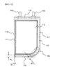
- FIG. 2 is a perspective view showing a battery cell according to an embodiment of the present invention
- FIG. 3 is a plan view showing the battery cell of FIG. 2
- FIG. 4 is a perspective view showing a battery case of the battery cell of FIG. 3 .
- a battery cell 100 is configured to have a structure including a battery case having a receiving part 112 provided with a round corner 150 and an electrode assembly (not shown) mounted in the receiving part 112.
- the battery case 110 includes an upper case 114 and a lower case 115 which are formed by bending a one-unit member.
- the receiving part 112 is formed at the upper case 114.
- the receiving part 112 is configured to have a depressed shape.
- the round corner is provided at one edge of the receiving part 112.
- the battery case 110 has sides 116, 117, 118, and 119. Sealed portions 160, which are formed at the upper case 114 and the lower case 115 by thermal welding, are located at the upper side 116 at which electrode terminals 140 are located, the first lateral side 117 adjacent to the upper side 116, and the lower side opposite to the upper side 116.
- the second lateral side 119 adjacent to the upper side 116 is formed by a bent structure of the battery case 110.
- the second lateral side 119 adjacent to the upper side 116, from which the electrode terminals 140 protrude is bent such that the upper case 114 covers the lower case 115, and the upper side 116, the lower side 118, and the first lateral side 117 are sealed by thermal welding.
- the round corner 150 is formed at an edge between the first lateral side 117 and the lower side 118.
- another round corner may also be formed at an edge between the first lateral side 117 and the upper side 116. That is, round corners may be formed at the edge between the first lateral side 117 and the upper side 116 and at the edge between the first lateral side 117 and the lower side 118.
- a thermally welded side located at a portion at which the round corner 150 is formed has a round corner corresponding to the shape of the round corner 150 of the receiving part 110.
- a width W1 of the side at which the round corner is formed is equal to a width W2 of the thermally welded sides at which no round corner is formed.
- the second side 119 is bent to form the upper case 114 and the lower case 115.
- a width W3 between a lateral side 111 of the receiving part 112 located in the bent direction and the second lateral side 119 is less than the width W1 of the side at which the round corner is formed and the width W2 of the thermally welded side at which no round corner is formed.
- a portion between the lateral side 111 of the receiving part 112 and the second lateral side 119 is not sealed. Consequently, the width W3 may be relatively small, or the width W3 may be 0 such that the lateral side of the receiving part is directly located at the bent portion.
- the bent structure of the battery case 20 is formed at the side opposite to the side from which the electrode leads 40 and 41 protrude in the same manner as in the pouch-shaped secondary battery 10 of FIG. 1 , and the round corner is formed such that the portion having the bent structure is included in the round corner, it is difficult to secure uniformity in sealing force of the round corner portion. That is, in a case in which internal pressure is increased in an abnormal situation, sealing of a portion having relatively low sealing force may be released due to a nonuniform sealed state.
- the battery case is configured to have a structure in which the portion having the round corner 150 and the side 119 having the bent structure are not adjacent to each other or do not overlap each other, whereby the sealed portion of the round corner 150 has uniform sealing force.
- the second lateral side 119 adjacent to the upper side 116 is formed by the bent structure of the battery case 110, and the round corner 150 is formed at the edge between the first lateral side 117 and the lower side 118.
- the electrode assembly may be provided with a round corner having a structure corresponding to the shape of the receiving part 110 having the round corner 150 such that the internal space of the receiving part can be maximally used.
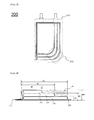
- FIG. 5 is a plan view showing a battery cell according to another embodiment of the present invention
- FIG. 6 is a vertical sectional view showing the battery cell of FIG. 5 .
- a battery cell 200 is configured to have a structure in which unit cells 212, 214, and 216 having different lengths AL, BL, and CL and capacities are mounted in a battery case 220 in a state in which the unit cells are vertically stacked.
- the vertically stacked type battery cell is configured to have a structure in which the thickness of the battery cell is gradually increased toward an electrode terminal 270 protruding outward from the battery case 220.
- a receiving part is configured to have a stepped structure for receiving the unit cells 212, 214, and 216.
- Round corners 250 are formed at one side of the receiving part.
- the round corners 250 are formed at edges of the receiving part in the same direction.
- the unit cells 212, 214, and 216 are stacked such that the planar sizes of the unit cells are gradually decreased from bottom to top, and the round corners 250 formed at the unit cells 212, 214, and 216 have different radii of curvature. That is, the radii of curvature of the unit cells are also gradually decreased from bottom to top.
- the capacities of the unit cells 212, 214, and 216 are proportional to products of the lengths AL, BL, and CL, heights AH-BH, BH-CH, and CH, and widths (not shown) of the respective unit cells 212, 214, and 216.
- a free space S3 is provided at the upper end of the right side of the battery cell due to the unit cells 212, 214, and 216 having different lengths AL, BL, and CL.
- the space is inversely proportional to the lengths, the heights, and the widths of the unit cells 212, 214, and 216.
- the space is provided to cope with a condition, such as an irregular internal space of a device, to which the battery cell is applied, or interference with other parts of the device.
- the direction in which the thickness of the battery cell is increased and the increase in stack thickness of the battery cell may be flexibly changed in design based on a situation applied to the battery cell.
- FIG. 7 is a plan view showing a battery cell according to a further embodiment of the present invention.
- the battery cell of FIG. 5 is configured such that three kinds of unit cells having different planar sizes are stacked, and therefore the receiving part is formed to have a three-step structure.
- a battery cell 300 is configured such that two kinds of unit cells having different planar sizes are stacked, and therefore a receiving part 312 is formed to have a two-step structure.
- round corners 350 having different radii of curvature are formed at the respective steps of the receiving part 312 in one edge direction.
- the unit cells having different planar sizes may be stacked to provide a structure having various other numbers of steps in addition to the three steps or the two steps as needed.
- a first unit cell is configured to have a structure in which a separator 310, a positive electrode 320, a separator 330, and a negative electrode 340 are laminated while being sequentially stacked.
- a second unit cell is configured to have a structure in which a separator 410, a positive electrode 420, and a separator 430 are laminated while being sequentially stacked.
- FIG. 10 shows a stacked type electrode assembly configured to have a structure in which the second unit cell of FIG. 9 is stacked on the uppermost end of a first unit cell stack constituted by first unit cells, one of which is shown in FIG. 8 .
- FIG. 11 shows an embodiment in which a fixing member T 1 is added to the first unit cell of FIG. 8 .
- the fixing member T 1 is added to the side or the front of the first unit cell 300.
- an additional fixing member may be added to the side of the stack structure to fix the stack structure.
- the fixing member may be realized as a tape T 1 surrounding the entire surface of the first unit cell 300 as shown in FIG. 11(a) .
- the fixing member may be realized as a fixing member T 2 to fix only each side of the first unit cell 300 as shown in FIG. 11(b) .
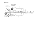
- FIG. 12 is a view typically showing a process of manufacturing the first unit cell according to the present invention.
- materials for a separator 310, a positive electrode 320, a separator 330, and a negative electrode 340 are simultaneously loaded (using sheet type loading units).
- the material for the positive electrode 320 which is used as a middle layer, is cut into a designed size, and is then loaded into laminators L 1 and L 2 .
- the materials for the separators 310 and 330, which are disposed under and above the material for the positive electrode 320, are simultaneously loaded into the laminators L 1 and L 2 .
- the material for the negative electrode 340 is loaded into the laminators L 1 and L 2 .
- the laminators L 1 and L 2 form a structural body in which the two electrodes and the two separators are laminated to each other using heat and pressure, i.e. a first unit cell.
- a cutter C 3 cuts the structural body into a plurality of first unit cells.
- various inspection processes such as a thickness inspection (a), a vision inspection (b), and a short circuit inspection (c), may be further performed with respect to each first unit cell.
- each first unit cell manufactured as described above is fixed using a fixing member, and the first unit cells are stacked to constitute a structural body in which the first unit cells are stacked.
- the second unit cell shown in FIG. 10 is stacked on the structural body and then the second unit cell and the structural body are fixed using a fixing member to complete a stacked type electrode assembly.
- an electrode assembly according to the present invention is formed by stacking unit cells having different sizes and includes a round corner having a curved structure. Consequently, it is possible for a battery cell including the electrode assembly to more accurately correspond to the shape, including a curved shape, of a device in which the battery cell is mounted and thus to further miniaturize the device.
- the battery cell is configured to have a structure to improve sealability of an edge portion at which the round corner is formed. Consequently, it is possible to secure safety of the battery cell.
Landscapes
- Chemical & Material Sciences (AREA)
- Chemical Kinetics & Catalysis (AREA)
- Electrochemistry (AREA)
- General Chemical & Material Sciences (AREA)
- Inorganic Chemistry (AREA)
- Sealing Battery Cases Or Jackets (AREA)
- Engineering & Computer Science (AREA)
- Manufacturing & Machinery (AREA)
- Secondary Cells (AREA)
- Connection Of Batteries Or Terminals (AREA)
- Battery Mounting, Suspending (AREA)
- Materials Engineering (AREA)
Abstract
Description
- The present invention relates to a battery cell configured to have a structure in which an electrode assembly, including positive electrodes, negative electrodes, and separators disposed respectively between the positive electrodes and the negative electrodes, is mounted in a battery case made of a laminate sheet including a resin layer and a metal layer, wherein the battery case is made of a one-unit member, which is bent to form an upper case and a lower case, at least one of the upper and lower cases is provided with a receiving part, in which the electrode assembly is mounted, the receiving part having a round corner formed at at least one side edge thereof, and sealed portions, which are formed at the upper case and the lower case by thermal welding, are located at an upper side of the battery case at which at least one electrode terminal is located, a first lateral side of the battery case adjacent to the upper side, and a lower side of the battery case opposite to the upper side, and a second lateral side of the battery case adjacent to the upper side is formed by a bent structure of the battery case.
- As mobile devices have been increasingly developed, and the demand for such mobile devices has increased, the demand for secondary batteries has also sharply increased. Among such secondary batteries is a lithium secondary battery exhibiting high energy density and operating voltage and excellent charge retention and service-life characteristics, which has been widely used as an energy source for various electronic products as well as mobile devices.
- Based on the appearance thereof, a lithium secondary battery may be generally classified as a cylindrical battery, a prismatic battery, or a pouch-shaped battery. Based on the type of an electrolyte, a lithium secondary battery may also be classified as a lithium ion battery, a lithium ion polymer battery, or a lithium polymer battery.
- A recent trend in the miniaturization of mobile devices has increased the demand for a prismatic battery or a pouch-shaped battery, which has a small thickness. In particular, much interest is currently focused on such a pouch-shaped battery because it is easy to modify the shape of the pouch-shaped battery, the manufacturing cost of the pouch-shaped battery is low, and the pouch-shaped battery is lightweight.
- In general, a pouch-shaped battery is a battery having an electrode assembly and an electrolyte in a pouch-shaped battery case, made of a laminate sheet including a resin layer and a metal layer, in a sealed state. The electrode assembly mounted in the battery case may be configured to have a jelly-roll (wound) type structure, a stacked type structure, or a combination (stacked/folded) type structure.
-
FIG. 1 is a view typically showing the structure of a pouch-shaped secondary battery including a stacked type electrode assembly. - Referring to
FIG. 1 , a pouch-shapedsecondary battery 10 is configured to have a structure in which anelectrode assembly 30, including positive electrodes, negative electrodes, and separators disposed respectively between the positive electrodes and the negative electrodes, each separator being coated with a solid electrolyte, is mounted in a pouch-shaped battery case 20 in a sealed state such that two electrode leads 40 and 41 electrically connected to positive electrode andnegative electrode tabs electrode assembly 30 are exposed outward. - The
battery case 20 includes acase body 21 having a depressed receivingpart 23, in which theelectrode assembly 30 is located, and a cover 22 integrally connected to thecase body 21. - The
battery case 20 is made of a laminate sheet including anouter resin layer 20A constituting the outermost layer of the laminate sheet, anisolation metal layer 20B for preventing penetration of materials, and an inner resin layer 20C for sealing. - The
positive electrode tabs 31 and thenegative electrode tabs 32 of the stackedtype electrode assembly 30 are respectively coupled to the electrode leads 40 and 41 by welding. In addition,insulative films 50 are attached to the top and bottom of each of the electrode leads 40 and 41 in order to prevent the occurrence of a short circuit between a thermal welding device (not shown) and the electrode leads 40 and 41 and to secure sealing between the electrode leads 40 and 41 and thebattery case 20 when theupper end 24 of thecase body 21 and the upper end of the cover 22 are thermally welded to each other using the thermal welding device. - In recent years, however, a new type of battery cell has been required in accordance with a trend change for a slim type design or various other designs.
- In addition, the above-mentioned battery cells may be configured to include electrode assemblies having the same size or the same capacity. For this reason, in order to manufacture a battery cell having a new structure in consideration of the design of a device, to which the battery cell is applied, it may be necessary to reduce the capacity of the battery cell or modify the design of the device such that the size of the device is increased.
- Furthermore, electrical connection may be complicated during modification of the design of the device with the result that it may be difficult to manufacture a battery cell satisfying desired conditions.
- Besides, it is necessary to manufacture the battery case based on the shape of the electrode assembly.
- Therefore, there is a high necessity for an electrode assembly and a battery case applicable depending upon the shape of a device, to which a battery cell is applied, and a battery cell including the same.
- The present invention has been made to solve the above problems and other technical problems that have yet to be resolved.
- Specifically, it is an object of the present invention to provide a battery cell configured to have a structure in which the battery cell can be mounted in various spaces of a device, whereby it is possible to maximally utilize an internal space of the device, and the battery cell can be efficiently mounted in various external structures of the device in addition to a rectangular external structure of the device.
- In accordance with one aspect of the present invention, the above and other objects can be accomplished by the provision of a battery cell configured to have a structure in which an electrode assembly, including positive electrodes, negative electrodes, and separators disposed respectively between the positive electrodes and the negative electrodes, is mounted in a battery case made of a laminate sheet including a resin layer and a metal layer, wherein the battery case is made of a one-unit member, which is bent to form an upper case and a lower case, at least one of the upper and lower cases is provided with a receiving part, in which the electrode assembly is mounted, the receiving part having a round corner formed at at least one side edge thereof, and sealed portions, which are formed at the upper case and the lower case by thermal welding, are located at an upper side of the battery case at which at least one electrode terminal is located, a first lateral side of the battery case adjacent to the upper side, and a lower side of the battery case opposite to the upper side, and a second lateral side of the battery case adjacent to the upper side is formed by a bent structure of the battery case.
- In the battery cell according to the present invention, the round corner is formed at the receiving part, in which the electrode assembly is mounted. Consequently, it is possible for the battery cell to more accurately correspond to the shape, including a curved shape, of a device in which the battery cell is mounted and thus to further miniaturize the device.
- The battery cell according to the present invention may be configured to have a structure in which the one-unit battery case is bent to form the upper case and the lower case, the electrode assembly is mounted in the receiving part formed at at least one of the upper and lower cases, the upper case covers the lower case, and the outer edge of the receiving part is sealed, thereby achieving sealing of the battery case.
- The positive electrodes and the negative electrodes of the electrode assembly may be connected to the electrode terminals protruding outward from the battery case, and the second lateral side of the battery case adjacent to the upper side of the battery case, from which the electrode terminals protrudes, may be bent such that the upper case covers the lower case. The upper side, the lower side, and the first lateral side of the battery case may be sealed by thermal welding. The number and position of round corners formed at the edges of the receiving part are not particularly restricted.
- For example, the round corner may be formed at at least one edge which does not abut on the upper side of the battery case. Specifically, the round corner may be formed at an edge between the lower side and the first lateral side of the battery case or at an edge between the lower side and the second lateral side of the battery case.
- In addition, the round corner may be formed at an edge of the first lateral side of the battery case. That is, the round corner may be formed at an edge between the first lateral side and the upper side of the battery case and/or at an edge between the first lateral side and the lower side of the battery case. At this time, the round corner may be formed at the other sides of the battery case excluding the side at which the battery case is bent and folded.
- In a concrete example, the round corner may have a maximum radius of curvature equivalent to 50% the length of the receiving part. The length of the receiving part may be the length of one side of the receiving part in a direction in which electrode leads protrude from the battery case or the length of one side of the receiving part in a direction perpendicular to the direction in which the electrode leads protrude from the battery case. More specifically, the length of one side of the receiving part in the direction in which the electrode leads protrude from the battery case may be shorter than that of one side of the receiving part in the direction perpendicular to the direction in which the electrode leads protrude from the battery case. At this time, the round corner may have a maximum radius of curvature equivalent to 50% the length of a long side of the receiving part. Specifically, the round corner may have a radius of curvature equivalent to 5 to 45% the length of the long side of the receiving part.
- In addition, a thermally welded side of the battery case corresponding to a portion at which the round corner of the receiving part is formed may have a round corner. At this time, the thermally welded side at which the round corner is formed may have the same width as the other thermally welded sides at which no round corner is formed. That is, the thermally welded sides may have the same width such that gas is prevented from leaking from the battery cell through the portion at which the round corner is formed when the internal pressure of the battery cell increases.
- Positive electrode tabs and negative electrode tabs may protrude from one side of the electrode assembly, or the positive electrode tabs may protrude from one side of the electrode assembly and the negative electrode tabs may protrude from the opposite side of the electrode assembly. Correspondingly, a positive electrode terminal and a negative electrode terminal may protrude from the upper side of the battery case, or the positive electrode terminal may protrude from the upper side of the battery case and the negative electrode terminal may protrude from the lower side of the battery case.
- In addition, in order to maximally use the internal space of the receiving part of the battery case and thus to further increase the capacity of the battery cell, the electrode assembly may have an external shape corresponding to an internal shape of the receiving part.
- In a concrete example, the electrode assembly may include two or more unit cells, each of the unit cells being configured to have a structure in which electrode tabs protrude from electrode plates.
- For example, the unit cells may be stacked in a vertical direction on the basis of a plane, and at least two of the unit cells may have different planar sizes.
- Each of the unit cells may be configured to have a structure in which round corners are formed at one or more edges. In addition, the edges of the unit cells at which the round corners are formed may be located in the same direction.
- The stacked structure of the unit cells is not particularly restricted. For example, the unit cells may be stacked such that sizes of the unit cells are gradually decreased from the bottom to the top of the electrode assembly to form a stair-shaped step. As compared with a conventional structure in which battery cells having different sizes are stacked, therefore, it is possible to minimize a dead space of the battery cell, thereby increasing a ratio of capacity to size of the battery cell, which is very preferable.
- Each of the unit cells of the electrode assembly is not particularly restricted so long as each of the unit cells constitutes a positive electrode and a negative electrode. For example, each of the unit cells may be configured to have a stacked type structure or a stacked/folded type structure. The details of the stacked/folded type electrode assembly are disclosed in Korean Patent Application Publication No.
2001-0082058 2001-0082059 2001-0082060 - An electrode assembly including a plurality of unit cells stacked in a vertical direction on the basis of a plane, at least two of the unit cells having different planar sizes, i.e. a stacked type electrode assembly may include a first unit cell configured to have a structure in which a positive electrode, a negative electrode, and separators are laminated while being stacked such that the positive electrode or the negative electrode is disposed between the separators. At this time, one of the separators may be a second separator.
- In addition, the stacked type electrode assembly may include a second unit cell configured to have a structure in which a positive electrode or a negative electrode and separators are laminated while being stacked such that the positive electrode or the negative electrode is disposed between the separators. At this time, one of the separators may be a second separator.
- For example, the first unit cell may be configured to have a structure in which a positive electrode, a separator, a negative electrode, and a separator are laminated while being sequentially stacked or a structure in which a negative electrode, a separator, a positive electrode, and a separator are laminated while being sequentially stacked.
- The stacked type electrode assembly may include a third unit cell configured to have a structure in which a positive electrode, a negative electrode, and a separator are laminated while being stacked such that the separator is disposed between the positive electrode and the negative electrode.
- The stacked type electrode assembly may include a fourth unit cell configured to have a structure in which a positive electrode or a negative electrode and a separator are laminated while being stacked.
- The stacked type electrode assembly may include any one selected from among the first unit cell, the second unit cell, the third unit cell, and the fourth unit cell or a combination thereof.
- The second unit cell may be stacked at the uppermost end or the lowermost end of the first unit cell.
- In a structure in which only the second unit cells are stacked, a positive electrode or a negative electrode may be disposed between the second unit cells.
- A fixing member to more securely maintain the stack structure of the positive electrode, the separator, and the negative electrode may be added to the first unit cell to the fourth unit cell.
- The fixing member may be an additional external member different from the first unit cell or the second unit cell. The fixing member may be an adhesive tape or a bonding tape to cover a portion or the entirety of the outside of each unit cell.
- The outside of each unit cell may include sides, a top, a front, and a rear.
- The fixing member may be a portion of the separator constituting each unit cell. In this case, the ends of the separator may be thermally welded to fix each unit cell. However, the present invention is not limited thereto.
- The ends of the separator may extend such that the separator has a length greater than the size of the positive electrode and the negative electrode, i.e. the horizontal length or the vertical length. The extending ends of the separator may be connected to each other by thermal welding.
- The fixing member may include all members that are capable of fixing the first unit cell or the second unit cell
- In a case in which the stacked type electrode assembly is configured to include the first unit cell and the second unit cell as described above, it is possible to improve productivity and yield as compared with a stacked type electrode assembly configured to have a structure in which a positive electrode, a negative electrode, and a separator are simply stacked.
- In addition, the positive electrode, the separators, and the negative electrode are laminated on a per first unit cell basis, and therefore it is possible to minimize expansion in volume of the stacked type electrode assembly due to swelling.
- In a case in which the stacked type electrode assembly is configured to include the first unit cell and the second unit cell, misalignment of the electrode assembly caused during a folding process is prevented and omission of processing equipment is possible. In addition, it is possible to form the first unit cell or the second unit cell using only one laminator. Furthermore, it is possible to manufacture the stacked type electrode assembly by simple stacking. Consequently, damage to electrodes caused during the folding process may be reduced, and electrolyte wettability may be improved. Moreover, a single-sided organic and inorganic composite separator, e.g. a safety reinforced separator (SRS), may be used as the separator exposed to the outside. Consequently, cell thickness may be decreased and, at the same time, processing cost may be reduced.
- The receiving part of the battery case may be configured to have a structure including a stair-shaped step corresponding to an external shape of the electrode assembly.
- According to the present invention, therefore, it is possible to manufacture battery cells having various capacities and sizes based on the above-described specific structure. In a case in which a device, in which the battery cell is mounted, is manufactured, the battery cell can be mounted in various spaces of the device, whereby it is possible to maximally utilize an internal space of the device.
- The battery cell may be a lithium ion battery cell or a lithium ion polymer battery cell. However, the present invention is not limited thereto.
- In accordance with another aspect of the present invention, there is provided a device including the battery cell with the above-stated construction as a power source. The device may be selected from among a mobile phone, a portable computer, a smart phone, a tablet PC, a smart pad, a netbook computer, a light electronic vehicle (LEV), an electric vehicle, a hybrid electric vehicle, a plug-in hybrid electric vehicle, and a power storage device.
- In accordance with a further aspect of the present invention, there is provided a battery pack including two or more battery cells with the above-stated construction as unit cells. That is, there is provided a battery pack configured to have a structure in which two or more battery cells as unit cells are connected in series and/or parallel to each other. The battery pack may be used in a device, such as a mobile phone, a portable computer, a smart phone, a tablet PC, a smart pad, a netbook computer, a light electronic vehicle (LEV), an electric vehicle, a hybrid electric vehicle, a plug-in hybrid electric vehicle, or a power storage device.
- The structure of the device and a method of manufacturing the device are well known in the art to which the present invention pertains, and therefore a detailed description thereof will be omitted.
- The above and other objects, features and other advantages of the present invention will be more clearly understood from the following detailed description taken in conjunction with the accompanying drawings, in which:
-
FIG. 1 is a perspective view showing a conventional battery cell; -
FIG. 2 is a perspective view showing a battery cell according to an embodiment of the present invention; -
FIG. 3 is a plan view showing the battery cell ofFIG. 2 ; -
FIG. 4 is a perspective view showing a battery case of the battery cell ofFIG. 3 ; -
FIG. 5 is a plan view showing a battery cell according to another embodiment of the present invention; -
FIG. 6 is a vertical sectional view showing the battery cell ofFIG. 5 ; -
FIG. 7 is a plan view showing a battery cell according to a further embodiment of the present invention; -
FIG. 8 is a view showing the structure of a first unit cell according to an embodiment of the present invention; -
FIG. 9 is a view showing the structure of a second unit cell according to an embodiment of the present invention; -
FIG. 10 is a typical view showing a stacked type electrode assembly according to an embodiment of the present invention; -
FIG. 11 is a typical view showing a fixing structure of the first unit cell ofFIG. 8 ; and -
FIG. 12 is a view showing a process of manufacturing a first unit cell according to an embodiment of the present invention - Now, exemplary embodiments of the present invention will be described in detail with reference to the accompanying drawings. It should be noted, however, that the scope of the present invention is not limited by the illustrated embodiments.
-
FIG. 2 is a perspective view showing a battery cell according to an embodiment of the present invention,FIG. 3 is a plan view showing the battery cell ofFIG. 2 , andFIG. 4 is a perspective view showing a battery case of the battery cell ofFIG. 3 . - Referring to these figures, a
battery cell 100 is configured to have a structure including a battery case having a receivingpart 112 provided with around corner 150 and an electrode assembly (not shown) mounted in the receivingpart 112. - The
battery case 110 includes anupper case 114 and alower case 115 which are formed by bending a one-unit member. The receivingpart 112 is formed at theupper case 114. The receivingpart 112 is configured to have a depressed shape. The round corner is provided at one edge of the receivingpart 112. - The
battery case 110 hassides Sealed portions 160, which are formed at theupper case 114 and thelower case 115 by thermal welding, are located at theupper side 116 at whichelectrode terminals 140 are located, the firstlateral side 117 adjacent to theupper side 116, and the lower side opposite to theupper side 116. The secondlateral side 119 adjacent to theupper side 116 is formed by a bent structure of thebattery case 110. - That is, the second
lateral side 119 adjacent to theupper side 116, from which theelectrode terminals 140 protrude is bent such that theupper case 114 covers thelower case 115, and theupper side 116, thelower side 118, and the firstlateral side 117 are sealed by thermal welding. - The
round corner 150 is formed at an edge between the firstlateral side 117 and thelower side 118. Although not shown, another round corner may also be formed at an edge between the firstlateral side 117 and theupper side 116. That is, round corners may be formed at the edge between the firstlateral side 117 and theupper side 116 and at the edge between the firstlateral side 117 and thelower side 118. - In addition, a thermally welded side located at a portion at which the
round corner 150 is formed has a round corner corresponding to the shape of theround corner 150 of the receivingpart 110. A width W1 of the side at which the round corner is formed is equal to a width W2 of the thermally welded sides at which no round corner is formed. - Meanwhile, the
second side 119 is bent to form theupper case 114 and thelower case 115. A width W3 between alateral side 111 of the receivingpart 112 located in the bent direction and the secondlateral side 119 is less than the width W1 of the side at which the round corner is formed and the width W2 of the thermally welded side at which no round corner is formed. A portion between thelateral side 111 of the receivingpart 112 and the secondlateral side 119 is not sealed. Consequently, the width W3 may be relatively small, or the width W3 may be 0 such that the lateral side of the receiving part is directly located at the bent portion. - On the other hand, in a case in which the bent structure of the
battery case 20 is formed at the side opposite to the side from which the electrode leads 40 and 41 protrude in the same manner as in the pouch-shapedsecondary battery 10 ofFIG. 1 , and the round corner is formed such that the portion having the bent structure is included in the round corner, it is difficult to secure uniformity in sealing force of the round corner portion. That is, in a case in which internal pressure is increased in an abnormal situation, sealing of a portion having relatively low sealing force may be released due to a nonuniform sealed state. - As shown in
FIGS. 2 and3 , therefore, the battery case is configured to have a structure in which the portion having theround corner 150 and theside 119 having the bent structure are not adjacent to each other or do not overlap each other, whereby the sealed portion of theround corner 150 has uniform sealing force. - That is, the second
lateral side 119 adjacent to theupper side 116 is formed by the bent structure of thebattery case 110, and theround corner 150 is formed at the edge between the firstlateral side 117 and thelower side 118. - The electrode assembly may be provided with a round corner having a structure corresponding to the shape of the receiving
part 110 having theround corner 150 such that the internal space of the receiving part can be maximally used. -
FIG. 5 is a plan view showing a battery cell according to another embodiment of the present invention, andFIG. 6 is a vertical sectional view showing the battery cell ofFIG. 5 . - Referring to
FIGS. 5 and 6 , abattery cell 200 is configured to have a structure in whichunit cells battery case 220 in a state in which the unit cells are vertically stacked. In addition, the vertically stacked type battery cell is configured to have a structure in which the thickness of the battery cell is gradually increased toward anelectrode terminal 270 protruding outward from thebattery case 220. - A receiving part is configured to have a stepped structure for receiving the
unit cells Round corners 250 are formed at one side of the receiving part. Theround corners 250 are formed at edges of the receiving part in the same direction. - The
unit cells round corners 250 formed at theunit cells - Meanwhile, the capacities of the
unit cells respective unit cells - In the above-described unique structure of the
battery cell 200, a free space S3 is provided at the upper end of the right side of the battery cell due to theunit cells unit cells - The space is provided to cope with a condition, such as an irregular internal space of a device, to which the battery cell is applied, or interference with other parts of the device. The direction in which the thickness of the battery cell is increased and the increase in stack thickness of the battery cell may be flexibly changed in design based on a situation applied to the battery cell.
-
FIG. 7 is a plan view showing a battery cell according to a further embodiment of the present invention. As described above, the battery cell ofFIG. 5 is configured such that three kinds of unit cells having different planar sizes are stacked, and therefore the receiving part is formed to have a three-step structure. As shown inFIG. 7 , on the other hand, abattery cell 300 is configured such that two kinds of unit cells having different planar sizes are stacked, and therefore a receivingpart 312 is formed to have a two-step structure. In addition,round corners 350 having different radii of curvature are formed at the respective steps of the receivingpart 312 in one edge direction. - That is, the unit cells having different planar sizes may be stacked to provide a structure having various other numbers of steps in addition to the three steps or the two steps as needed.
- As shown in
FIG. 8 , a first unit cell is configured to have a structure in which aseparator 310, apositive electrode 320, aseparator 330, and anegative electrode 340 are laminated while being sequentially stacked. - As shown in
FIG. 9 , a second unit cell is configured to have a structure in which aseparator 410, apositive electrode 420, and aseparator 430 are laminated while being sequentially stacked. -
FIG. 10 shows a stacked type electrode assembly configured to have a structure in which the second unit cell ofFIG. 9 is stacked on the uppermost end of a first unit cell stack constituted by first unit cells, one of which is shown inFIG. 8 . -
FIG. 11 shows an embodiment in which a fixing member T1 is added to the first unit cell ofFIG. 8 . Specifically, the fixing member T1 is added to the side or the front of thefirst unit cell 300. - In order to secure stack stability of a simple stack structure, an additional fixing member may be added to the side of the stack structure to fix the stack structure. The fixing member may be realized as a tape T1 surrounding the entire surface of the
first unit cell 300 as shown inFIG. 11(a) . Alternatively, the fixing member may be realized as a fixing member T2 to fix only each side of thefirst unit cell 300 as shown inFIG. 11(b) . -
FIG. 12 is a view typically showing a process of manufacturing the first unit cell according to the present invention. - As shown in
FIG. 12 , materials for aseparator 310, apositive electrode 320, aseparator 330, and anegative electrode 340 are simultaneously loaded (using sheet type loading units). The material for thepositive electrode 320, which is used as a middle layer, is cut into a designed size, and is then loaded into laminators L1 and L2. Subsequently, the materials for theseparators positive electrode 320, are simultaneously loaded into the laminators L1 and L2. At the same time, the material for thenegative electrode 340 is loaded into the laminators L1 and L2. - Subsequently, the laminators L1 and L2 form a structural body in which the two electrodes and the two separators are laminated to each other using heat and pressure, i.e. a first unit cell. Subsequently, a cutter C3 cuts the structural body into a plurality of first unit cells. Afterwards, various inspection processes, such as a thickness inspection (a), a vision inspection (b), and a short circuit inspection (c), may be further performed with respect to each first unit cell.
- Subsequently, each first unit cell manufactured as described above is fixed using a fixing member, and the first unit cells are stacked to constitute a structural body in which the first unit cells are stacked. Subsequently, the second unit cell shown in
FIG. 10 is stacked on the structural body and then the second unit cell and the structural body are fixed using a fixing member to complete a stacked type electrode assembly. - Although the exemplary embodiments of the present invention have been disclosed for illustrative purposes, those skilled in the art will appreciate that various modifications, additions and substitutions are possible, without departing from the scope and spirit of the invention as disclosed in the accompanying claims.
- As is apparent from the above description, an electrode assembly according to the present invention is formed by stacking unit cells having different sizes and includes a round corner having a curved structure. Consequently, it is possible for a battery cell including the electrode assembly to more accurately correspond to the shape, including a curved shape, of a device in which the battery cell is mounted and thus to further miniaturize the device.
- In addition, the battery cell is configured to have a structure to improve sealability of an edge portion at which the round corner is formed. Consequently, it is possible to secure safety of the battery cell.
Claims (26)
- A battery cell configured to have a structure in which an electrode assembly, comprising positive electrodes, negative electrodes, and separators disposed respectively between the positive electrodes and the negative electrodes, is mounted in a battery case made of a laminate sheet comprising a resin layer and a metal layer, wherein
the battery case is made of a one-unit member, which is bent to form an upper case and a lower case,
at least one of the upper and lower cases is provided with a receiving part, in which the electrode assembly is mounted, the receiving part having a round corner formed at at least one side edge thereof, and
sealed portions, which are formed at the upper case and the lower case by thermal welding, are located at an upper side of the battery case at which at least one electrode terminal is located, a first lateral side of the battery case adjacent to the upper side, and a lower side of the battery case opposite to the upper side, and a second lateral side of the battery case adjacent to the upper side is formed by a bent structure of the battery case. - The battery cell according to claim 1, wherein the battery case is bent at the second lateral side such that the upper case and the lower case are thermally welded to each other in tight contact at the other sides of the battery case.
- The battery cell according to claim 1, wherein the round corner is formed at at least one edge which does not abut on the upper side of the battery case.
- The battery cell according to claim 1, wherein the round corner is formed at an edge of the first lateral side of the battery case.
- The battery cell according to claim 1, wherein the round corner has a maximum radius of curvature equivalent to 50% a length of a long side of the receiving part.
- The battery cell according to claim 5, wherein the round corner has a radius of curvature equivalent to 5 to 45% the length of the long side of the receiving part.
- The battery cell according to claim 1, wherein a thermally welded side of the battery case corresponding to a portion at which the round corner of the receiving part is formed has a round corner.
- The battery cell according to claim 7, wherein the thermally welded side at which the round corner is formed has the same width as the other thermally welded sides at which no round corner is formed.
- The battery cell according to claim 1, wherein a positive electrode terminal and a negative electrode terminal protrude from the upper side of the battery case, or the positive electrode terminal protrudes from the upper side of the battery case and the negative electrode terminal protrudes from the lower side of the battery case.
- The battery cell according to claim 1, wherein the electrode assembly has an external shape corresponding to an internal shape of the receiving part.
- The battery cell according to claim 1, wherein the electrode assembly comprises two or more unit cells, each of the unit cells being configured to have a structure in which electrode tabs protrude from electrode plates, and a round corner is formed at at least one edge.
- The battery cell according to claim 11, wherein the unit cells are stacked in a vertical direction on the basis of a plane, and at least two of the unit cells have different planar sizes.
- The battery cell according to claim 11, wherein edges of the unit cells at which the round corners are formed are located in the same direction.
- The battery cell according to claim 11, wherein the unit cells are stacked such that sizes of the unit cells are gradually decreased from a bottom to a top of the electrode assembly to form a stair-shaped step.
- The battery cell according to claim 14, wherein the unit cells are stacked such that radii of curvature of the round corners are gradually decreased from the bottom to the top of the electrode assembly.
- The battery cell according to claim 11, wherein each of the unit cells of the electrode assembly is configured to have a stacked type structure or a stacked/folded type structure.
- The battery cell according to claim 16, wherein each of the unit cells is a stacked type unit cell comprising a positive electrode, a negative electrode, a first plate-shaped separator disposed between the positive electrode and the negative electrode, the positive electrode and the negative electrode being stacked in a vertical direction on the basis of a plane in a state in which the separator is disposed between the positive electrode and the negative electrode.
- The battery cell according to claim 17, wherein the stacked type unit cell comprises a first unit cell configured to have a structure in which a positive electrode, a negative electrode, and separators are laminated while being stacked such that any one of the positive electrode and the negative electrode is located an outermost side of the unit cell, and the outermost positive electrode or the outermost negative electrode is disposed between the separators.
- The battery cell according to claim 17, wherein the stacked type unit cell comprises a second unit cell configured to have a structure in which a positive electrode, a negative electrode, and separators are laminated while being stacked such that the separators are located at outermost sides of the unit cell, and any one of the positive electrode and the negative electrode is disposed between the separators.
- The battery cell according to claim 15, wherein the receiving part of the battery case is provided with a stair-shaped step corresponding to an external shape of the electrode assembly.
- The battery cell according to claim 1, wherein the battery cell is a lithium ion battery cell or a lithium ion polymer battery cell.
- A battery pack comprising two or more battery cells according to any one of claims 1 to 21 as unit cells.
- A device comprising a battery cell according to any one of claims 1 to 21 as a power source.
- The device according to claim 23, wherein the device is selected from a group consisting of a mobile phone, a portable computer, a smart phone, a tablet PC, a smart pad, a netbook computer, a light electronic vehicle (LEV), an electric vehicle, a hybrid electric vehicle, a plug-in hybrid electric vehicle, and a power storage device.
- A device comprising a battery pack according to claim 22 as a power source.
- The device according to claim 25, wherein the device is selected from a group consisting of a mobile phone, a portable computer, a smart phone, a tablet PC, a smart pad, a netbook computer, a light electronic vehicle (LEV), an electric vehicle, a hybrid electric vehicle, a plug-in hybrid electric vehicle, and a power storage device.
Applications Claiming Priority (2)
| Application Number | Priority Date | Filing Date | Title |
|---|---|---|---|
| KR20130039743 | 2013-04-11 | ||
| PCT/KR2014/003028 WO2014168397A1 (en) | 2013-04-11 | 2014-04-08 | Battery cell having rounded corner |
Publications (3)
| Publication Number | Publication Date |
|---|---|
| EP2940753A1 true EP2940753A1 (en) | 2015-11-04 |
| EP2940753A4 EP2940753A4 (en) | 2016-06-15 |
| EP2940753B1 EP2940753B1 (en) | 2018-02-14 |
Family
ID=51689751
Family Applications (1)
| Application Number | Title | Priority Date | Filing Date |
|---|---|---|---|
| EP14782417.1A Active EP2940753B1 (en) | 2013-04-11 | 2014-04-08 | Battery cell having rounded corner |
Country Status (6)
| Country | Link |
|---|---|
| US (1) | US9741974B2 (en) |
| EP (1) | EP2940753B1 (en) |
| JP (1) | JP6240223B2 (en) |
| KR (2) | KR20140123007A (en) |
| CN (1) | CN105122494B (en) |
| WO (1) | WO2014168397A1 (en) |
Cited By (2)
| Publication number | Priority date | Publication date | Assignee | Title |
|---|---|---|---|---|
| EP4113684A4 (en) * | 2021-02-04 | 2024-04-24 | LG Energy Solution, Ltd. | Lamination device and method for discharging defective electrode cell assembly of lamination device |
| EP4346586A4 (en) * | 2021-05-31 | 2024-10-30 | Medtrum Technologies Inc. | Battery shell integrated analyte detection device |
Families Citing this family (29)
| Publication number | Priority date | Publication date | Assignee | Title |
|---|---|---|---|---|
| KR101192619B1 (en) * | 2012-03-23 | 2012-10-18 | 주식회사 엘지화학 | Battery case |
| US10937999B2 (en) * | 2014-11-28 | 2021-03-02 | Semiconductor Energy Laboratory Co., Ltd. | Secondary battery and manufacturing method of the same |
| US11251484B2 (en) * | 2016-09-26 | 2022-02-15 | Envision Aesc Japan Ltd. | Assembly including unit cell and spacer |
| WO2018100927A1 (en) * | 2016-11-29 | 2018-06-07 | 株式会社村田製作所 | Secondary cell and device |
| CN110036501B (en) * | 2016-12-06 | 2022-05-13 | 株式会社村田制作所 | Secondary battery |
| WO2018117654A1 (en) | 2016-12-20 | 2018-06-28 | 에스케이이노베이션 주식회사 | Pouch-type secondary battery and manufacturing method therefor |
| EP4738561A2 (en) * | 2016-12-20 | 2026-05-06 | SK On Co., Ltd. | Pouch-type secondary battery and fabricating method therefor |
| JP6773133B2 (en) * | 2017-01-13 | 2020-10-21 | 株式会社村田製作所 | Rechargeable battery |
| JP6828753B2 (en) | 2017-01-26 | 2021-02-10 | 株式会社村田製作所 | Stacked secondary battery and its manufacturing method and device |
| WO2018138976A1 (en) | 2017-01-26 | 2018-08-02 | 株式会社村田製作所 | Stacked rechargeable battery, method for producing same, and device |
| CN107293802B (en) * | 2017-07-28 | 2023-03-21 | 鹤壁市诺信电子有限公司 | Fillet heating mechanism for lithium battery |
| WO2019044560A1 (en) | 2017-08-31 | 2019-03-07 | 株式会社村田製作所 | Secondary cell and method for manufacturing same |
| CN111033789A (en) * | 2017-08-31 | 2020-04-17 | 株式会社村田制作所 | Electricity storage device |
| KR102238177B1 (en) * | 2017-09-15 | 2021-04-07 | 주식회사 엘지화학 | Battery cell and method of preparing electrode lead |
| KR102347884B1 (en) | 2017-10-17 | 2022-01-06 | 주식회사 엘지에너지솔루션 | Sealing Block to Prevent Crack of Pouch-Type Secondary Battery, Pouch-Type Battery Case and Sealing Method for Pouch-Type Battery Case Using thereof |
| CN109962284A (en) * | 2017-12-22 | 2019-07-02 | 宁德新能源科技有限公司 | Electrochemical device and method for manufacturing the same |
| CN111213277B (en) * | 2018-03-23 | 2023-10-24 | Tdk株式会社 | Nonaqueous electrolyte secondary battery |
| US20220218240A1 (en) * | 2019-08-19 | 2022-07-14 | Medtrum Technologies Inc. | Sensing device |
| CN111009681B (en) * | 2019-12-30 | 2025-05-27 | 广东微电新能源股份有限公司 | Energy storage device |
| KR102839736B1 (en) * | 2020-05-06 | 2025-07-28 | 주식회사 엘지에너지솔루션 | Manufacturing method for secondary battery having improved resistance |
| KR20220052459A (en) * | 2020-10-21 | 2022-04-28 | 주식회사 엘지에너지솔루션 | Welding device having an electrode tab fixing member and Electrode tab welding method using the same |
| JP7670495B2 (en) * | 2021-02-01 | 2025-04-30 | 本田技研工業株式会社 | battery |
| US12476312B2 (en) | 2021-04-15 | 2025-11-18 | Lg Energy Solution, Ltd. | Secondary battery |
| US12294105B2 (en) | 2021-04-15 | 2025-05-06 | Lg Energy Solution, Ltd. | Secondary battery |
| EP4346588A4 (en) * | 2021-05-31 | 2024-10-30 | Medtrum Technologies Inc. | Highly integrated analyte detection device |
| CN117581408A (en) * | 2021-06-25 | 2024-02-20 | 松下知识产权经营株式会社 | Battery |
| KR20230073506A (en) * | 2021-11-19 | 2023-05-26 | 주식회사 엘지에너지솔루션 | Secondary battery and battery module including the same |
| CN114335737B (en) * | 2021-12-15 | 2024-03-29 | 深圳市首通新能源科技有限公司 | Method for sealing edges of flexible package lithium ion battery and lithium ion battery |
| DE102024109564A1 (en) | 2024-04-05 | 2025-10-09 | Audi Aktiengesellschaft | Housing component for a cell housing with integrated cell separator, battery cell and method for producing a device with a cell separator |
Family Cites Families (27)
| Publication number | Priority date | Publication date | Assignee | Title |
|---|---|---|---|---|
| JP2000149994A (en) * | 1998-11-17 | 2000-05-30 | Toshiba Battery Co Ltd | Polymer electrolyte lithium secondary battery |
| JP4498514B2 (en) | 2000-01-18 | 2010-07-07 | 大日本印刷株式会社 | Battery container |
| JP4621325B2 (en) | 2000-01-19 | 2011-01-26 | 株式会社東芝 | Thin battery |
| KR100497147B1 (en) | 2000-02-08 | 2005-06-29 | 주식회사 엘지화학 | Multiply stacked electrochemical cell and method for preparing the same |
| KR100515572B1 (en) | 2000-02-08 | 2005-09-20 | 주식회사 엘지화학 | Stacked electrochemical cell and method for preparing the same |
| KR100515571B1 (en) | 2000-02-08 | 2005-09-20 | 주식회사 엘지화학 | Stacked electrochemical cell |
| JP2002015713A (en) | 2000-06-30 | 2002-01-18 | Toshiba Corp | Lithium ion secondary battery |
| US20040048149A1 (en) * | 2001-10-30 | 2004-03-11 | Oliver Gross | Battery packaging construction |
| KR100440934B1 (en) | 2002-02-06 | 2004-07-21 | 삼성에스디아이 주식회사 | Secondary battery |
| WO2005074054A1 (en) * | 2004-01-30 | 2005-08-11 | Lg Chem, Ltd. | Battery having specific package structure |
| KR100850865B1 (en) * | 2004-01-30 | 2008-08-07 | 주식회사 엘지화학 | Battery having specific package structure |
| JP2006114406A (en) * | 2004-10-15 | 2006-04-27 | Toyota Motor Corp | Sheet material type battery manufacturing method, sheet material type battery, and assembled battery combining sheet material type single cell |
| KR100884945B1 (en) | 2006-04-03 | 2009-02-23 | 주식회사 엘지화학 | Pouch Type Secondary Battery |
| KR100805153B1 (en) | 2006-04-25 | 2008-02-21 | 삼성에스디아이 주식회사 | Battery module |
| TW200814480A (en) | 2006-07-10 | 2008-03-16 | Hitachi Ltd | Distribution switchgear |
| KR101302075B1 (en) * | 2006-12-08 | 2013-09-05 | 주식회사 엘지화학 | Couple structure of electrode tab and terminal for secondary battery and Secondary battery having the same |
| CN100447334C (en) | 2006-12-08 | 2008-12-31 | 姜在胜 | Kraft white paperboard |
| KR101029837B1 (en) * | 2009-01-06 | 2011-04-15 | 주식회사 엘지화학 | Novel battery module and medium and large battery packs comprising the same |
| CN102884665B (en) | 2010-04-06 | 2015-09-30 | 株式会社Lg化学 | Improved stacked battery cell or double battery cell, electrode assembly for secondary battery using same and manufacturing method thereof |
| KR101191635B1 (en) | 2010-05-24 | 2012-10-17 | 삼성에스디아이 주식회사 | Pouch for rechageable battery, fabricating method of the same and rechargeable battery including the pouch |
| US8940429B2 (en) * | 2010-07-16 | 2015-01-27 | Apple Inc. | Construction of non-rectangular batteries |
| US8592065B2 (en) * | 2010-11-02 | 2013-11-26 | Apple Inc. | Rechargeable battery with a jelly roll having multiple thicknesses |
| JP5784928B2 (en) | 2011-03-03 | 2015-09-24 | シャープ株式会社 | Non-aqueous secondary battery |
| CN103125031A (en) * | 2011-06-22 | 2013-05-29 | 株式会社Lg化学 | Pouch and pouch type secondary battery |
| JP5875803B2 (en) | 2011-08-29 | 2016-03-02 | 三洋電機株式会社 | Non-aqueous electrolyte secondary battery and manufacturing method thereof |
| US9276287B2 (en) * | 2011-10-28 | 2016-03-01 | Apple Inc. | Non-rectangular batteries for portable electronic devices |
| EP2958177B1 (en) * | 2013-03-08 | 2017-05-31 | Lg Chem, Ltd. | Electrode assembly having rounded corners |
-
2014
- 2014-04-07 KR KR20140041117A patent/KR20140123007A/en not_active Ceased
- 2014-04-08 JP JP2015555934A patent/JP6240223B2/en active Active
- 2014-04-08 US US14/653,054 patent/US9741974B2/en active Active
- 2014-04-08 EP EP14782417.1A patent/EP2940753B1/en active Active
- 2014-04-08 CN CN201480006565.9A patent/CN105122494B/en active Active
- 2014-04-08 WO PCT/KR2014/003028 patent/WO2014168397A1/en not_active Ceased
-
2015
- 2015-11-16 KR KR1020150160289A patent/KR20150134304A/en not_active Ceased
Cited By (2)
| Publication number | Priority date | Publication date | Assignee | Title |
|---|---|---|---|---|
| EP4113684A4 (en) * | 2021-02-04 | 2024-04-24 | LG Energy Solution, Ltd. | Lamination device and method for discharging defective electrode cell assembly of lamination device |
| EP4346586A4 (en) * | 2021-05-31 | 2024-10-30 | Medtrum Technologies Inc. | Battery shell integrated analyte detection device |
Also Published As
| Publication number | Publication date |
|---|---|
| CN105122494A (en) | 2015-12-02 |
| EP2940753A4 (en) | 2016-06-15 |
| US9741974B2 (en) | 2017-08-22 |
| KR20140123007A (en) | 2014-10-21 |
| US20160020434A1 (en) | 2016-01-21 |
| JP2016505204A (en) | 2016-02-18 |
| JP6240223B2 (en) | 2017-11-29 |
| WO2014168397A1 (en) | 2014-10-16 |
| CN105122494B (en) | 2017-09-19 |
| KR20150134304A (en) | 2015-12-01 |
| EP2940753B1 (en) | 2018-02-14 |
Similar Documents
| Publication | Publication Date | Title |
|---|---|---|
| US9741974B2 (en) | Battery cell having round corner | |
| US9203058B2 (en) | Battery cell of asymmetric structure and battery pack employed with the same | |
| EP2802025B1 (en) | Battery cell having stair-like structure | |
| EP2958177B1 (en) | Electrode assembly having rounded corners | |
| KR101402657B1 (en) | Battery Pack of Irregular Structure | |
| EP2958180A1 (en) | Battery cell having novel structure and enhanced safety | |
| KR101580086B1 (en) | Electrode Assembly of Combination Structure | |
| EP2916365B1 (en) | Electric device comprising round corner | |
| EP2843747B1 (en) | Stepped electrode assembly having excellent stacked shape stability and manufacturing method therefor |
Legal Events
| Date | Code | Title | Description |
|---|---|---|---|
| PUAI | Public reference made under article 153(3) epc to a published international application that has entered the european phase |
Free format text: ORIGINAL CODE: 0009012 |
|
| 17P | Request for examination filed |
Effective date: 20150728 |
|
| AK | Designated contracting states |
Kind code of ref document: A1 Designated state(s): AL AT BE BG CH CY CZ DE DK EE ES FI FR GB GR HR HU IE IS IT LI LT LU LV MC MK MT NL NO PL PT RO RS SE SI SK SM TR |
|
| AX | Request for extension of the european patent |
Extension state: BA ME |
|
| A4 | Supplementary search report drawn up and despatched |
Effective date: 20160517 |
|
| RIC1 | Information provided on ipc code assigned before grant |
Ipc: H01M 2/02 20060101AFI20160510BHEP |
|
| DAX | Request for extension of the european patent (deleted) | ||
| STAA | Information on the status of an ep patent application or granted ep patent |
Free format text: STATUS: EXAMINATION IS IN PROGRESS |
|
| 17Q | First examination report despatched |
Effective date: 20170206 |
|
| GRAP | Despatch of communication of intention to grant a patent |
Free format text: ORIGINAL CODE: EPIDOSNIGR1 |
|
| STAA | Information on the status of an ep patent application or granted ep patent |
Free format text: STATUS: GRANT OF PATENT IS INTENDED |
|
| INTG | Intention to grant announced |
Effective date: 20171124 |
|
| GRAS | Grant fee paid |
Free format text: ORIGINAL CODE: EPIDOSNIGR3 |
|
| GRAA | (expected) grant |
Free format text: ORIGINAL CODE: 0009210 |
|
| STAA | Information on the status of an ep patent application or granted ep patent |
Free format text: STATUS: THE PATENT HAS BEEN GRANTED |
|
| AK | Designated contracting states |
Kind code of ref document: B1 Designated state(s): AL AT BE BG CH CY CZ DE DK EE ES FI FR GB GR HR HU IE IS IT LI LT LU LV MC MK MT NL NO PL PT RO RS SE SI SK SM TR |
|
| REG | Reference to a national code |
Ref country code: GB Ref legal event code: FG4D |
|
| REG | Reference to a national code |
Ref country code: CH Ref legal event code: EP |
|
| REG | Reference to a national code |
Ref country code: IE Ref legal event code: FG4D |
|
| REG | Reference to a national code |
Ref country code: DE Ref legal event code: R096 Ref document number: 602014020983 Country of ref document: DE Ref country code: AT Ref legal event code: REF Ref document number: 970403 Country of ref document: AT Kind code of ref document: T Effective date: 20180315 |
|
| REG | Reference to a national code |
Ref country code: FR Ref legal event code: PLFP Year of fee payment: 5 |
|
| REG | Reference to a national code |
Ref country code: NL Ref legal event code: MP Effective date: 20180214 |
|
| REG | Reference to a national code |
Ref country code: AT Ref legal event code: MK05 Ref document number: 970403 Country of ref document: AT Kind code of ref document: T Effective date: 20180214 |
|
| PG25 | Lapsed in a contracting state [announced via postgrant information from national office to epo] |
Ref country code: HR Free format text: LAPSE BECAUSE OF FAILURE TO SUBMIT A TRANSLATION OF THE DESCRIPTION OR TO PAY THE FEE WITHIN THE PRESCRIBED TIME-LIMIT Effective date: 20180214 Ref country code: LT Free format text: LAPSE BECAUSE OF FAILURE TO SUBMIT A TRANSLATION OF THE DESCRIPTION OR TO PAY THE FEE WITHIN THE PRESCRIBED TIME-LIMIT Effective date: 20180214 Ref country code: CY Free format text: LAPSE BECAUSE OF FAILURE TO SUBMIT A TRANSLATION OF THE DESCRIPTION OR TO PAY THE FEE WITHIN THE PRESCRIBED TIME-LIMIT Effective date: 20180214 Ref country code: NL Free format text: LAPSE BECAUSE OF FAILURE TO SUBMIT A TRANSLATION OF THE DESCRIPTION OR TO PAY THE FEE WITHIN THE PRESCRIBED TIME-LIMIT Effective date: 20180214 Ref country code: ES Free format text: LAPSE BECAUSE OF FAILURE TO SUBMIT A TRANSLATION OF THE DESCRIPTION OR TO PAY THE FEE WITHIN THE PRESCRIBED TIME-LIMIT Effective date: 20180214 Ref country code: NO Free format text: LAPSE BECAUSE OF FAILURE TO SUBMIT A TRANSLATION OF THE DESCRIPTION OR TO PAY THE FEE WITHIN THE PRESCRIBED TIME-LIMIT Effective date: 20180514 Ref country code: FI Free format text: LAPSE BECAUSE OF FAILURE TO SUBMIT A TRANSLATION OF THE DESCRIPTION OR TO PAY THE FEE WITHIN THE PRESCRIBED TIME-LIMIT Effective date: 20180214 |
|
| PG25 | Lapsed in a contracting state [announced via postgrant information from national office to epo] |
Ref country code: AT Free format text: LAPSE BECAUSE OF FAILURE TO SUBMIT A TRANSLATION OF THE DESCRIPTION OR TO PAY THE FEE WITHIN THE PRESCRIBED TIME-LIMIT Effective date: 20180214 Ref country code: LV Free format text: LAPSE BECAUSE OF FAILURE TO SUBMIT A TRANSLATION OF THE DESCRIPTION OR TO PAY THE FEE WITHIN THE PRESCRIBED TIME-LIMIT Effective date: 20180214 Ref country code: SE Free format text: LAPSE BECAUSE OF FAILURE TO SUBMIT A TRANSLATION OF THE DESCRIPTION OR TO PAY THE FEE WITHIN THE PRESCRIBED TIME-LIMIT Effective date: 20180214 Ref country code: GR Free format text: LAPSE BECAUSE OF FAILURE TO SUBMIT A TRANSLATION OF THE DESCRIPTION OR TO PAY THE FEE WITHIN THE PRESCRIBED TIME-LIMIT Effective date: 20180515 Ref country code: BG Free format text: LAPSE BECAUSE OF FAILURE TO SUBMIT A TRANSLATION OF THE DESCRIPTION OR TO PAY THE FEE WITHIN THE PRESCRIBED TIME-LIMIT Effective date: 20180514 Ref country code: RS Free format text: LAPSE BECAUSE OF FAILURE TO SUBMIT A TRANSLATION OF THE DESCRIPTION OR TO PAY THE FEE WITHIN THE PRESCRIBED TIME-LIMIT Effective date: 20180214 |
|
| PG25 | Lapsed in a contracting state [announced via postgrant information from national office to epo] |
Ref country code: AL Free format text: LAPSE BECAUSE OF FAILURE TO SUBMIT A TRANSLATION OF THE DESCRIPTION OR TO PAY THE FEE WITHIN THE PRESCRIBED TIME-LIMIT Effective date: 20180214 Ref country code: PL Free format text: LAPSE BECAUSE OF FAILURE TO SUBMIT A TRANSLATION OF THE DESCRIPTION OR TO PAY THE FEE WITHIN THE PRESCRIBED TIME-LIMIT Effective date: 20180214 Ref country code: EE Free format text: LAPSE BECAUSE OF FAILURE TO SUBMIT A TRANSLATION OF THE DESCRIPTION OR TO PAY THE FEE WITHIN THE PRESCRIBED TIME-LIMIT Effective date: 20180214 Ref country code: IT Free format text: LAPSE BECAUSE OF FAILURE TO SUBMIT A TRANSLATION OF THE DESCRIPTION OR TO PAY THE FEE WITHIN THE PRESCRIBED TIME-LIMIT Effective date: 20180214 Ref country code: RO Free format text: LAPSE BECAUSE OF FAILURE TO SUBMIT A TRANSLATION OF THE DESCRIPTION OR TO PAY THE FEE WITHIN THE PRESCRIBED TIME-LIMIT Effective date: 20180214 |
|
| REG | Reference to a national code |
Ref country code: DE Ref legal event code: R097 Ref document number: 602014020983 Country of ref document: DE |
|
| PG25 | Lapsed in a contracting state [announced via postgrant information from national office to epo] |
Ref country code: SK Free format text: LAPSE BECAUSE OF FAILURE TO SUBMIT A TRANSLATION OF THE DESCRIPTION OR TO PAY THE FEE WITHIN THE PRESCRIBED TIME-LIMIT Effective date: 20180214 Ref country code: SM Free format text: LAPSE BECAUSE OF FAILURE TO SUBMIT A TRANSLATION OF THE DESCRIPTION OR TO PAY THE FEE WITHIN THE PRESCRIBED TIME-LIMIT Effective date: 20180214 Ref country code: CZ Free format text: LAPSE BECAUSE OF FAILURE TO SUBMIT A TRANSLATION OF THE DESCRIPTION OR TO PAY THE FEE WITHIN THE PRESCRIBED TIME-LIMIT Effective date: 20180214 Ref country code: MC Free format text: LAPSE BECAUSE OF FAILURE TO SUBMIT A TRANSLATION OF THE DESCRIPTION OR TO PAY THE FEE WITHIN THE PRESCRIBED TIME-LIMIT Effective date: 20180214 Ref country code: DK Free format text: LAPSE BECAUSE OF FAILURE TO SUBMIT A TRANSLATION OF THE DESCRIPTION OR TO PAY THE FEE WITHIN THE PRESCRIBED TIME-LIMIT Effective date: 20180214 |
|
| REG | Reference to a national code |
Ref country code: CH Ref legal event code: PL |
|
| REG | Reference to a national code |
Ref country code: BE Ref legal event code: MM Effective date: 20180430 |
|
| PLBE | No opposition filed within time limit |
Free format text: ORIGINAL CODE: 0009261 |
|
| STAA | Information on the status of an ep patent application or granted ep patent |
Free format text: STATUS: NO OPPOSITION FILED WITHIN TIME LIMIT |
|
| 26N | No opposition filed |
Effective date: 20181115 |
|
| REG | Reference to a national code |
Ref country code: IE Ref legal event code: MM4A |
|
| PG25 | Lapsed in a contracting state [announced via postgrant information from national office to epo] |
Ref country code: LU Free format text: LAPSE BECAUSE OF NON-PAYMENT OF DUE FEES Effective date: 20180408 |
|
| PG25 | Lapsed in a contracting state [announced via postgrant information from national office to epo] |
Ref country code: BE Free format text: LAPSE BECAUSE OF NON-PAYMENT OF DUE FEES Effective date: 20180430 Ref country code: CH Free format text: LAPSE BECAUSE OF NON-PAYMENT OF DUE FEES Effective date: 20180430 Ref country code: LI Free format text: LAPSE BECAUSE OF NON-PAYMENT OF DUE FEES Effective date: 20180430 Ref country code: SI Free format text: LAPSE BECAUSE OF FAILURE TO SUBMIT A TRANSLATION OF THE DESCRIPTION OR TO PAY THE FEE WITHIN THE PRESCRIBED TIME-LIMIT Effective date: 20180214 |
|
| PG25 | Lapsed in a contracting state [announced via postgrant information from national office to epo] |
Ref country code: IE Free format text: LAPSE BECAUSE OF NON-PAYMENT OF DUE FEES Effective date: 20180408 |
|
| PG25 | Lapsed in a contracting state [announced via postgrant information from national office to epo] |
Ref country code: MT Free format text: LAPSE BECAUSE OF NON-PAYMENT OF DUE FEES Effective date: 20180408 |
|
| PG25 | Lapsed in a contracting state [announced via postgrant information from national office to epo] |
Ref country code: TR Free format text: LAPSE BECAUSE OF FAILURE TO SUBMIT A TRANSLATION OF THE DESCRIPTION OR TO PAY THE FEE WITHIN THE PRESCRIBED TIME-LIMIT Effective date: 20180214 |
|
| PG25 | Lapsed in a contracting state [announced via postgrant information from national office to epo] |
Ref country code: PT Free format text: LAPSE BECAUSE OF FAILURE TO SUBMIT A TRANSLATION OF THE DESCRIPTION OR TO PAY THE FEE WITHIN THE PRESCRIBED TIME-LIMIT Effective date: 20180214 |
|
| PG25 | Lapsed in a contracting state [announced via postgrant information from national office to epo] |
Ref country code: HU Free format text: LAPSE BECAUSE OF FAILURE TO SUBMIT A TRANSLATION OF THE DESCRIPTION OR TO PAY THE FEE WITHIN THE PRESCRIBED TIME-LIMIT; INVALID AB INITIO Effective date: 20140408 Ref country code: MK Free format text: LAPSE BECAUSE OF NON-PAYMENT OF DUE FEES Effective date: 20180214 |
|
| PG25 | Lapsed in a contracting state [announced via postgrant information from national office to epo] |
Ref country code: IS Free format text: LAPSE BECAUSE OF FAILURE TO SUBMIT A TRANSLATION OF THE DESCRIPTION OR TO PAY THE FEE WITHIN THE PRESCRIBED TIME-LIMIT Effective date: 20180614 |
|
| REG | Reference to a national code |
Ref country code: DE Ref legal event code: R079 Ref document number: 602014020983 Country of ref document: DE Free format text: PREVIOUS MAIN CLASS: H01M0002020000 Ipc: H01M0050100000 |
|
| P01 | Opt-out of the competence of the unified patent court (upc) registered |
Effective date: 20230512 |
|
| REG | Reference to a national code |
Ref country code: DE Ref legal event code: R081 Ref document number: 602014020983 Country of ref document: DE Owner name: LG ENERGY SOLUTION, LTD., KR Free format text: FORMER OWNER: LG CHEM, LTD., SEOUL, KR |
|
| REG | Reference to a national code |
Ref country code: GB Ref legal event code: 732E Free format text: REGISTERED BETWEEN 20230824 AND 20230831 |
|
| PGFP | Annual fee paid to national office [announced via postgrant information from national office to epo] |
Ref country code: DE Payment date: 20250320 Year of fee payment: 12 |
|
| PGFP | Annual fee paid to national office [announced via postgrant information from national office to epo] |
Ref country code: GB Payment date: 20260324 Year of fee payment: 13 |
|
| PGFP | Annual fee paid to national office [announced via postgrant information from national office to epo] |
Ref country code: FR Payment date: 20260323 Year of fee payment: 13 |