EP2940689A2 - Cable storage under a drawer - Google Patents
Cable storage under a drawer Download PDFInfo
- Publication number
- EP2940689A2 EP2940689A2 EP15163730.3A EP15163730A EP2940689A2 EP 2940689 A2 EP2940689 A2 EP 2940689A2 EP 15163730 A EP15163730 A EP 15163730A EP 2940689 A2 EP2940689 A2 EP 2940689A2
- Authority
- EP
- European Patent Office
- Prior art keywords
- cables
- drawer
- appendage
- flattening
- securing
- Prior art date
- Legal status (The legal status is an assumption and is not a legal conclusion. Google has not performed a legal analysis and makes no representation as to the accuracy of the status listed.)
- Granted
Links
Images



Classifications
-
- H—ELECTRICITY
- H05—ELECTRIC TECHNIQUES NOT OTHERWISE PROVIDED FOR
- H05K—PRINTED CIRCUITS; CASINGS OR CONSTRUCTIONAL DETAILS OF ELECTRIC APPARATUS; MANUFACTURE OF ASSEMBLAGES OF ELECTRICAL COMPONENTS
- H05K5/00—Casings, cabinets or drawers for electric apparatus
- H05K5/02—Details
- H05K5/0247—Electrical details of casings, e.g. terminals, passages for cables or wiring
-
- G—PHYSICS
- G11—INFORMATION STORAGE
- G11B—INFORMATION STORAGE BASED ON RELATIVE MOVEMENT BETWEEN RECORD CARRIER AND TRANSDUCER
- G11B33/00—Constructional parts, details or accessories not provided for in the other groups of this subclass
- G11B33/12—Disposition of constructional parts in the apparatus, e.g. of power supply, of modules
- G11B33/125—Disposition of constructional parts in the apparatus, e.g. of power supply, of modules the apparatus comprising a plurality of recording/reproducing devices, e.g. modular arrangements, arrays of disc drives
- G11B33/126—Arrangements for providing electrical connections, e.g. connectors, cables, switches
-
- A—HUMAN NECESSITIES
- A47—FURNITURE; DOMESTIC ARTICLES OR APPLIANCES; COFFEE MILLS; SPICE MILLS; SUCTION CLEANERS IN GENERAL
- A47B—TABLES; DESKS; OFFICE FURNITURE; CABINETS; DRAWERS; GENERAL DETAILS OF FURNITURE
- A47B88/00—Drawers for tables, cabinets or like furniture; Guides for drawers
- A47B88/40—Sliding drawers; Slides or guides therefor
-
- A—HUMAN NECESSITIES
- A47—FURNITURE; DOMESTIC ARTICLES OR APPLIANCES; COFFEE MILLS; SPICE MILLS; SUCTION CLEANERS IN GENERAL
- A47B—TABLES; DESKS; OFFICE FURNITURE; CABINETS; DRAWERS; GENERAL DETAILS OF FURNITURE
- A47B96/00—Details of cabinets, racks or shelf units not covered by a single one of groups A47B43/00 - A47B95/00; General details of furniture
-
- H—ELECTRICITY
- H05—ELECTRIC TECHNIQUES NOT OTHERWISE PROVIDED FOR
- H05K—PRINTED CIRCUITS; CASINGS OR CONSTRUCTIONAL DETAILS OF ELECTRIC APPARATUS; MANUFACTURE OF ASSEMBLAGES OF ELECTRICAL COMPONENTS
- H05K7/00—Constructional details common to different types of electric apparatus
- H05K7/14—Mounting supporting structure in casing or on frame or rack
- H05K7/1485—Servers; Data center rooms, e.g. 19-inch computer racks
- H05K7/1487—Blade assemblies, e.g. blade cases or inner arrangements within a blade
-
- H—ELECTRICITY
- H05—ELECTRIC TECHNIQUES NOT OTHERWISE PROVIDED FOR
- H05K—PRINTED CIRCUITS; CASINGS OR CONSTRUCTIONAL DETAILS OF ELECTRIC APPARATUS; MANUFACTURE OF ASSEMBLAGES OF ELECTRICAL COMPONENTS
- H05K7/00—Constructional details common to different types of electric apparatus
- H05K7/14—Mounting supporting structure in casing or on frame or rack
- H05K7/1485—Servers; Data center rooms, e.g. 19-inch computer racks
- H05K7/1488—Cabinets therefor, e.g. chassis or racks or mechanical interfaces between blades and support structures
- H05K7/1491—Cabinets therefor, e.g. chassis or racks or mechanical interfaces between blades and support structures having cable management arrangements
Definitions
- the disclosure generally relates to cable organization in a server chassis.
- Cables used in connecting hardware on a server (e.g., hard drives, motherboard, etc.) to a server chassis are prone to being tangled when the server or hard disk drawer is pulled out and pushed back into the chassis.
- a cable support mechanism is used for solving this problem.
- a cable arm positioned at the back of the chassis is adapted to extend and retract along with the server or hard disk drawer while also supporting the cables.
- the cables are attached to the cable arm, which comprises a foldable set of bars.
- cable arms require a lot of space and also obstruct heat dissipation from the server blade out of the chassis
- an apparatus can be configured to store cables underneath a hardware drawer of a computing device.
- the apparatus comprises a wall of a drawer adapted to secure a set of cables at a first end.
- the wall can be coupled to a roller and a flattening appendage.
- the cables can be housed in a cable housing.
- the cable housing can be a mylar belt.
- the cable housing can be a microchain.
- the apparatus can comprise a deck comprising a plate adapted to secure the set of cables at a second end, the plate located at a midpoint of the deck.
- a drawer is adapted to slide along the deck, a shelf attached to the drawer.
- the flattening appendage presses down on the first end of the set of cables and the roller presses down on the second end of the set of cables as the drawer is opened and closed such that the set of cables is stored neatly under the drawer.
- Particular implementations provide at least the following advantages: Compact storage and organization of server cables underneath a server blade, additional space available at the rear of a server chassis, and improved heat dissipation from the server blade out of the server chassis due to less clutter at the rear of the chassis.
- Coupled is defined as connected, whether directly or indirectly through intervening members, and is not necessarily limited to physical connections.
- the connection can be such that the objects are permanently connected or releasably connected.
- substantially is defined to be essentially conforming to the particular dimension, shape or other word that substantially modifies, such that the member need not be exact. For example, substantially cylindrical means that the object resembles a cylinder, but can have one or more deviations from a true cylinder.
- comprising when utilized, means “including, but not necessarily limited to”; it specifically indicates open-ended inclusion or membership in the so-described combination, group, series and the like.
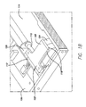
- FIGS. 1A and 1B illustrate an example cable storage apparatus 100 for storing cables 104 underneath drawer 106 (e.g. a hard drive drawer, server drawer, etc.) while drawer 106 is in a fully closed position.
- drawer 106 e.g. a hard drive drawer, server drawer, etc.
- FIGS. 1A and 1B drawer 106 is in a fully closed position, with cables 104 stored completely underneath drawer106.
- rear wall 126 can be used to secure a first end (e.g., upper end) of cables 104. This can be accomplished by any means known in the art.
- a securing piece (not shown) can be coupled to rear wall 126such that cables 104 are sandwiched between the securing piece and rear wall 126.
- the securing piece can be coupled to rear wall 126according to means known in the art, including, but not limited to, snap attachments, screws, friction fit, etc.
- the securing piece can be coupled to shelf 102 using similar means.
- cables 104 can be sandwiched between the securing piece and shelf 102, and securing piece can be attached either above or below shelf 102.
- shelf 102 can be substantially flat in shape, and can be made of metal, plastic, rubber, etc. Alternatively, shelf can comprise cable aperture 112 for cables 104 to pass through to couple with cable couplings located on drawer 106. In some implementations shelf 102 is attached to rear wall 126 of drawer 106. Attachment of shelf 102 to drawer 106 can be accomplished using any means known in the art, including, but not limited to, screws, friction fit, snap attachment, etc. For example, shelf 102 can be fixed in place on drawer 106 such that a first end of cables 104 follows the motion of drawer 106 as drawer 106 is pulled out and pushed in from chassis 116. Alternatively, shelf 102 can be fixed closer to one side of chassis 116.
- chassis 116 can be adapted to work in combination with drawer 106 to allow drawer 106 to be opened and closed (e.g. similar to a desk drawer).
- chassis 116 can include side walls 128 with guiding portions and drawer 106 can include sliding portions that slide along the guiding portions. Guiding portions can include wheels and locking mechanisms to prevent drawer 106 from sliding out all the way.
- Drawer 106 can include wheels and locking mechanisms that move through the guiding portions to allow drawer 106 to slide into and out of chassis 116.
- the width of drawer 106 can be smaller than the width of chassis 116.
- one of the side walls 128 can be positioned closer to the other side wall 128 to support drawer 106 (see e.g., FIG. 1A ).
- shelf 102 can comprise roller 110.
- roller 110 can be substantially cylindrical in shape and can be made of any material known in the art with frictional characteristics such as, but not limited to, plastic, rubber, etc.
- roller 110 can be located below shelf 102 and can be used for pushing down a second end (e.g., lower end) of cables 104 towards deck 114 as drawer 106 is opened and closed.
- roller 110 can be adapted to roll along the second end of cables 104 according to methods known in the art, including, but not limited to, bearings, axles, wheels, etc., to push or press the second end of the cables to the floor of the chassis. Roller 110 therefore helps keep cables 104 organized while guiding cables 104 underneath drawer 106.
- roller 110 can be the same width as cables 104.
- shelf 102 can comprise flattening appendage 108.
- Flattening appendage 108 can be a flat and rigid planar extension of shelf 102.
- flattening appendage 108 can be used to flatten a first end of cables 104 as shelf 106 is opened and closed. As shelf 106 gets closer to the rear of chassis 116, cables 104 tend to bunch and spring up. Flattening appendage 108 ensures that cables 104 remain pressed down, organized and do not bunch up.
- flattening appendage 108 can be the same width as cables 104, and can further comprise guides 118 for keeping cables 104 underneath flattening appendage 108.
- Flattening appendage can be made of the same material as shelf 102, as described above.
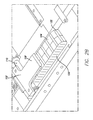
- FIGS. 2A and 2B illustrate drawer 106 half open with cables 104 housed inside a cable housing 120.
- cable housing 120 keeps cables 104 together and organized.
- cable housing 120 can include a mylar belt.
- cable housing 120 can include a microchain.
- a second end of cables 104 e.g., the lower portion
- Roller 110 rolls over cables 104 to ensure smooth deployment of the second end of cables 104, and flattening appendage 108 ensures the first end of cables 104 remains flat.
- cable housing 120 comprises a mylar belt.
- Mylar is a polyester film made from stretched polyethylene terephthalate (PET) and is used for high tensile strength, chemical and dimensional stability, transparency, reflectivity, gas and aroma barrier properties, and electrical insulation.
- PET stretched polyethylene terephthalate
- the mylar belt can comprise securing straps 122 that span across the width of cables 104 to secure cables 104 to the mylar belt.
- securing straps 122 are also made of mylar.
- the mylar belt can be situated on one side of cables 104, as securing straps 122 span across the opposite side (as shown in FIGS. 2A and 2B ).
- the mylar belt can house cables 104 to keep them together while shelf 102 pushes and pulls against cables 104 as drawer 106 is opened and closed.
- the mylar belt can add rigidity to cables 104 to prevent pinching or binding of cables 104.
- cable housing can be adapted to span the portion of cables 104 between shelf 102 and plate 124 (as shown in FIGS. 3A and 3B ).
- cable housing 120 can comprise a microchain for securing cables 104, as described below with reference to FIG. 3 .
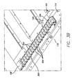
- FIGS. 3A and 3B illustrate drawer 106 fully open with cables 104 housed inside microchain 300. When drawer 106 is fully open, cable 104 is fully extended and exposed.
- a second end of cables 104 can be secured on deck 114.
- the second end of cables 104 can be secured underneath plate 124.
- Plate 124 can be secured to deck 114 (e.g., the bottom of the chassis) according to means known in the art, including, but not limited to, screws, snap fit, friction fit, hinges, etc.
- plate 124 can be adapted to open and close to easily allow securing of cables 104 to deck 114. Cables 104 fold underneath plate 124 and continue towards the rear of chassis 116 (as shown in FIG. 3B ).
- plate 124 can be located at a midway point of deck 114.
- plate 124 can be located at a midway point of deck 114 and towards a side of chassis 116.
- shelf 102 is attached to rear wall 126 such that shelf 102 is in line with plate 124.
- cables 104 Because the first and second ends of cables 104 are secured at shelf 102 and under plate 124, the free movement of cables 104 is limited. Cable housing 120 that spans between shelf 102 and plate 124 further limits the free movement of cables 104. As a result, drawer 106 can be opened and closed with minimal interruption from cables 104.
- microchain 300 can comprise a plurality of segments 302 interlinked together through joints 304 such that joints 304 are pivotable and allow microchain 300 as a whole to be flexible to move with cables 104. Segments 302 can be adapted to house cables 104 and provide support above and below cables 104. For example, cables 104 can reside within microchain 300, and microchain 300 keeps cables 104 organized. Joints 304 can be interlinked according to methods known in the art, including, but not limited to, interlocking links, pivoting joints, knuckle joints, etc.
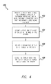
- FIG. 4 is a flow diagram 400 of an example method for storing a cable under a drawer.
- the method described below can be carried out using the configurations illustrated in FIGS. 1-3 , for example, and various elements of these figures are referenced in explaining the example method.
- Each block shown in FIG. 4 represents one or more processes, methods or subroutines, carried out in the example method.
- the illustrated order of blocks is illustrative only and the order of the blocks can change according to the present disclosure. Additional blocks can be added or fewer blocks may be utilized, without departing from this disclosure.
- the example method begins at block 402.
- a device is provided with a wall of a drawer, a roller, a flattening appendage, and a deck comprising a plate, operably connected such that the drawer slides along the deck.
- the device can be structured according any of the described implementations above for cable storage under a drawer.
- a first end of the set of cables is secured at the wall of the drawer.
- the first of end of the set of cables can be secured according to above-described implementations, including, but not limited to, using a securing piece.
- a second end of the set of cables is secured at the plate.
- the deck comprises a plate for securing the set of cables, as described above.
- the drawer is closed such that the flattening appendage presses down on the first end of the set of cables and the roller presses down on the second end of the set of cables such that the set of cables is stored under the drawer.
- the roller and flattening appendage work in combination to keep the set of cables organized and from rising up as the drawer is closed, as described above.
- a cable housing is used to keep the set of cables together and organized, as described above.
- drawer 106 For clarity and simplicity, only drawer 106 is described. However, multiple drawers comprising multiple shelves and chasses can be supported by the above disclosure. For example, multiple drawers can be stored on top of each other, as commonly known in server architecture, each chassis adapted store cables underneath each drawer according to the disclosure herein.
Landscapes
- Engineering & Computer Science (AREA)
- Microelectronics & Electronic Packaging (AREA)
- Computer Hardware Design (AREA)
- General Engineering & Computer Science (AREA)
- Drawers Of Furniture (AREA)
Abstract
Description
- The disclosure generally relates to cable organization in a server chassis.
- Cables used in connecting hardware on a server (e.g., hard drives, motherboard, etc.) to a server chassis are prone to being tangled when the server or hard disk drawer is pulled out and pushed back into the chassis. Conventionally, a cable support mechanism is used for solving this problem. For example, a cable arm positioned at the back of the chassis is adapted to extend and retract along with the server or hard disk drawer while also supporting the cables. The cables are attached to the cable arm, which comprises a foldable set of bars. However, cable arms require a lot of space and also obstruct heat dissipation from the server blade out of the chassis
- In some implementations, an apparatus can be configured to store cables underneath a hardware drawer of a computing device. The apparatus comprises a wall of a drawer adapted to secure a set of cables at a first end. For example, the wall can be coupled to a roller and a flattening appendage. The cables can be housed in a cable housing. The cable housing can be a mylar belt. The cable housing can be a microchain. In some implementations, the apparatus can comprise a deck comprising a plate adapted to secure the set of cables at a second end, the plate located at a midpoint of the deck. Alternatively, a drawer is adapted to slide along the deck, a shelf attached to the drawer. The flattening appendage presses down on the first end of the set of cables and the roller presses down on the second end of the set of cables as the drawer is opened and closed such that the set of cables is stored neatly under the drawer.
- Particular implementations provide at least the following advantages: Compact storage and organization of server cables underneath a server blade, additional space available at the rear of a server chassis, and improved heat dissipation from the server blade out of the server chassis due to less clutter at the rear of the chassis.
- Details of one or more implementations are set forth in the accompanying drawings and the description below. Other features, aspects, and potential advantages will be apparent from the description and drawings, and from the claims.
-
-
FIG. 1A is an isometric view of a cable storage apparatus showing a drawer in a closed position with cables stored underneath the drawer. -
FIG. 1B is a close-up view of the apparatus ofFIG. 1A . -
FIG. 2A is an isometric view of a cable storage apparatus showing the drawer pulled halfway out. -
FIG. 2B is a close-up view of the apparatus ofFIG. 2A . -
FIG. 3A is an isometric view of a cable storage apparatus showing the drawer pulled all the way out. -
FIG. 3B is a close-up view of the apparatus ofFIG. 3A . -
FIG. 4 is a flow diagram of an example method for storing a cable under a drawer. - Like reference symbols in the various drawings indicate like elements.
- It will be appreciated that for simplicity and clarity of illustration, where appropriate, reference numerals have been repeated among the different figures to indicate corresponding or analogous elements. In addition, numerous specific details are set forth in order to provide a thorough understanding of the embodiments described herein. However, it will be understood by those of ordinary skill in the art that the embodiments described herein can be practiced without these specific details. In other instances, methods, procedures and members have not been described in detail so as not to obscure the related relevant feature being described. Also, the description is not to be considered as limiting the scope of the embodiments described herein. The drawings are not necessarily to scale and the proportions of certain parts have been exaggerated to better illustrate details and features of the present disclosure.
- Several definitions that apply throughout this disclosure will now be presented.
- The term "coupled" is defined as connected, whether directly or indirectly through intervening members, and is not necessarily limited to physical connections. The connection can be such that the objects are permanently connected or releasably connected. The term "substantially" is defined to be essentially conforming to the particular dimension, shape or other word that substantially modifies, such that the member need not be exact. For example, substantially cylindrical means that the object resembles a cylinder, but can have one or more deviations from a true cylinder. The term "comprising," when utilized, means "including, but not necessarily limited to"; it specifically indicates open-ended inclusion or membership in the so-described combination, group, series and the like.
- In practice, as a drawer is pulled out of a chassis from a closed position, to a halfway open position, to an open position, cables that are completely stored underneath the drawer become exposed and fully extended. As the drawer is closed, the cables return under the drawer until they are fully stored underneath the drawer. The space saved from having the cables stored underneath the drawer allows for more space on the drawer for hardware, and improved ventilation at the rear of the chassis for heat dissipation.
-
FIGS. 1A and1B illustrate an examplecable storage apparatus 100 for storingcables 104 underneath drawer 106 (e.g. a hard drive drawer, server drawer, etc.) whiledrawer 106 is in a fully closed position. As shown inFIGS. 1A and1B ,drawer 106 is in a fully closed position, withcables 104 stored completely underneath drawer106. In some implementations,rear wall 126 can be used to secure a first end (e.g., upper end) ofcables 104. This can be accomplished by any means known in the art. For example, a securing piece (not shown) can be coupled to rear wall 126such thatcables 104 are sandwiched between the securing piece andrear wall 126. The securing piece can be coupled to rear wall 126according to means known in the art, including, but not limited to, snap attachments, screws, friction fit, etc. Alternatively, the securing piece can be coupled toshelf 102 using similar means. For example,cables 104 can be sandwiched between the securing piece andshelf 102, and securing piece can be attached either above or belowshelf 102. - In some implementations,
shelf 102 can be substantially flat in shape, and can be made of metal, plastic, rubber, etc. Alternatively, shelf can comprisecable aperture 112 forcables 104 to pass through to couple with cable couplings located ondrawer 106. In someimplementations shelf 102 is attached torear wall 126 ofdrawer 106. Attachment ofshelf 102 todrawer 106 can be accomplished using any means known in the art, including, but not limited to, screws, friction fit, snap attachment, etc. For example,shelf 102 can be fixed in place ondrawer 106 such that a first end ofcables 104 follows the motion ofdrawer 106 asdrawer 106 is pulled out and pushed in fromchassis 116. Alternatively,shelf 102 can be fixed closer to one side ofchassis 116. - In some implementations,
chassis 116 can be adapted to work in combination withdrawer 106 to allowdrawer 106 to be opened and closed (e.g. similar to a desk drawer). For example,chassis 116 can includeside walls 128 with guiding portions anddrawer 106 can include sliding portions that slide along the guiding portions. Guiding portions can include wheels and locking mechanisms to preventdrawer 106 from sliding out all the way.Drawer 106 can include wheels and locking mechanisms that move through the guiding portions to allowdrawer 106 to slide into and out ofchassis 116. Alternatively, the width ofdrawer 106 can be smaller than the width ofchassis 116. For example, one of theside walls 128 can be positioned closer to theother side wall 128 to support drawer 106 (see e.g.,FIG. 1A ). - In some
implementations shelf 102 can compriseroller 110. For example,roller 110 can be substantially cylindrical in shape and can be made of any material known in the art with frictional characteristics such as, but not limited to, plastic, rubber, etc. Alternatively,roller 110 can be located belowshelf 102 and can be used for pushing down a second end (e.g., lower end) ofcables 104 towardsdeck 114 asdrawer 106 is opened and closed. For example,roller 110 can be adapted to roll along the second end ofcables 104 according to methods known in the art, including, but not limited to, bearings, axles, wheels, etc., to push or press the second end of the cables to the floor of the chassis.Roller 110 therefore helps keepcables 104 organized while guidingcables 104 underneathdrawer 106. Alternatively,roller 110 can be the same width ascables 104. - In some implementations,
shelf 102 can comprise flatteningappendage 108. Flatteningappendage 108 can be a flat and rigid planar extension ofshelf 102. For example, flatteningappendage 108 can be used to flatten a first end ofcables 104 asshelf 106 is opened and closed. Asshelf 106 gets closer to the rear ofchassis 116,cables 104 tend to bunch and spring up. Flatteningappendage 108 ensures thatcables 104 remain pressed down, organized and do not bunch up. Alternatively, flatteningappendage 108 can be the same width ascables 104, and can further compriseguides 118 for keepingcables 104 underneath flatteningappendage 108. Flattening appendage can be made of the same material asshelf 102, as described above. -
FIGS. 2A and2B illustratedrawer 106 half open withcables 104 housed inside acable housing 120. For example,cable housing 120 keepscables 104 together and organized. In some implementations,cable housing 120 can include a mylar belt. In some implementations,cable housing 120 can include a microchain. Asdrawer 106 is opened from the closed position inFIGS. 1A and1B to the half open position depicted inFIGS. 2A and2B , a second end of cables 104 (e.g., the lower portion) that was previously stored beneathdrawer 106 becomes exposed.Roller 110 rolls overcables 104 to ensure smooth deployment of the second end ofcables 104, and flatteningappendage 108 ensures the first end ofcables 104 remains flat. - In some implementations,
cable housing 120 comprises a mylar belt. Mylar is a polyester film made from stretched polyethylene terephthalate (PET) and is used for high tensile strength, chemical and dimensional stability, transparency, reflectivity, gas and aroma barrier properties, and electrical insulation. Alternatively, the mylar belt can comprise securingstraps 122 that span across the width ofcables 104 to securecables 104 to the mylar belt. In some implementations, securingstraps 122 are also made of mylar. For example, the mylar belt can be situated on one side ofcables 104, as securingstraps 122 span across the opposite side (as shown inFIGS. 2A and2B ). The mylar belt can housecables 104 to keep them together whileshelf 102 pushes and pulls againstcables 104 asdrawer 106 is opened and closed. The mylar belt can add rigidity tocables 104 to prevent pinching or binding ofcables 104. Alternatively, cable housing can be adapted to span the portion ofcables 104 betweenshelf 102 and plate 124 (as shown inFIGS. 3A and3B ). In some implementations,cable housing 120 can comprise a microchain for securingcables 104, as described below with reference toFIG. 3 . -
FIGS. 3A and3B illustratedrawer 106 fully open withcables 104 housed insidemicrochain 300. Whendrawer 106 is fully open,cable 104 is fully extended and exposed. - In some implementations, a second end of
cables 104 can be secured ondeck 114. For example, the second end ofcables 104 can be secured underneathplate 124.Plate 124 can be secured to deck 114 (e.g., the bottom of the chassis) according to means known in the art, including, but not limited to, screws, snap fit, friction fit, hinges, etc. Alternatively,plate 124 can be adapted to open and close to easily allow securing ofcables 104 todeck 114.Cables 104 fold underneathplate 124 and continue towards the rear of chassis 116 (as shown inFIG. 3B ). In some implementations,plate 124 can be located at a midway point ofdeck 114. Alternatively,plate 124 can be located at a midway point ofdeck 114 and towards a side ofchassis 116. In some implementations,shelf 102 is attached torear wall 126 such thatshelf 102 is in line withplate 124. - Because the first and second ends of
cables 104 are secured atshelf 102 and underplate 124, the free movement ofcables 104 is limited.Cable housing 120 that spans betweenshelf 102 andplate 124 further limits the free movement ofcables 104. As a result,drawer 106 can be opened and closed with minimal interruption fromcables 104. - In some implementations,
microchain 300 can comprise a plurality ofsegments 302 interlinked together throughjoints 304 such thatjoints 304 are pivotable and allowmicrochain 300 as a whole to be flexible to move withcables 104.Segments 302 can be adapted tohouse cables 104 and provide support above and belowcables 104. For example,cables 104 can reside withinmicrochain 300, andmicrochain 300 keepscables 104 organized.Joints 304 can be interlinked according to methods known in the art, including, but not limited to, interlocking links, pivoting joints, knuckle joints, etc. - Referring to
FIG. 4 is a flow diagram 400 of an example method for storing a cable under a drawer. The method described below can be carried out using the configurations illustrated inFIGS. 1-3 , for example, and various elements of these figures are referenced in explaining the example method. Each block shown inFIG. 4 represents one or more processes, methods or subroutines, carried out in the example method. Furthermore, the illustrated order of blocks is illustrative only and the order of the blocks can change according to the present disclosure. Additional blocks can be added or fewer blocks may be utilized, without departing from this disclosure. The example method begins atblock 402. - At
block 402, a device is provided with a wall of a drawer, a roller, a flattening appendage, and a deck comprising a plate, operably connected such that the drawer slides along the deck. The device can be structured according any of the described implementations above for cable storage under a drawer. - At
block 404, a first end of the set of cables is secured at the wall of the drawer. The first of end of the set of cables can be secured according to above-described implementations, including, but not limited to, using a securing piece. - At
block 406, a second end of the set of cables is secured at the plate. In some implementations, the deck comprises a plate for securing the set of cables, as described above. - At
block 408, the drawer is closed such that the flattening appendage presses down on the first end of the set of cables and the roller presses down on the second end of the set of cables such that the set of cables is stored under the drawer. The roller and flattening appendage work in combination to keep the set of cables organized and from rising up as the drawer is closed, as described above. In some implementations, a cable housing is used to keep the set of cables together and organized, as described above. - A number of implementations have been described. Nevertheless, it will be understood that various modifications may be made. For example, other steps may be provided, or steps may be eliminated, from the described methods, and other components may be added to, or removed from, the described systems. Accordingly, other implementations are within the scope of the following claims.
- For clarity and simplicity, only
drawer 106 is described. However, multiple drawers comprising multiple shelves and chasses can be supported by the above disclosure. For example, multiple drawers can be stored on top of each other, as commonly known in server architecture, each chassis adapted store cables underneath each drawer according to the disclosure herein.
Claims (15)
- An apparatus comprising:a wall (126) of a drawer (106) adapted to secure a set of cables (104) at a first end, the wall (126) coupled to a roller (110) and a flattening appendage (108);a deck (114) comprising a plate (124), the plate (124) adapted to secure the set of cables (104) at a second end; anda drawer (106) adapted to slide along the deck (114) and over the plate (124);wherein the flattening appendage (108) presses down on the first end of the set of cables (104) and the roller (110) presses down on the second end of the set of cables (104) as the drawer (106) is opened and closed such that the set of cables (104) is stored under the drawer (106).
- The apparatus of claim 1 wherein the wall (126) comprises a securing piece for securing the set of cables (104), and the securing piece attaches below the flattening appendage (108).
- The apparatus of any one of claims 1 and 2 further comprising a cable housing (120) for housing the set of cables (104) and securing the cables (104) together.
- The apparatus of claim 3 wherein the cable housing (120) comprises a mylar belt or a microchain (300).
- The apparatus of any one of claims 3 and 4 wherein the cable housing (120) spans the set of cables (104) between the first end and the second end.
- A method comprising:providing a device with a wall (126) of a drawer (106), a roller (110), a flattening appendage (108), and a deck (114) comprising a plate (124), operably connected such that the drawer (106) slides along the deck (114);securing a first end of the set of cables (104) at the wall (126) of the drawer (106);securing a second end of the set of cables (104) at the plate (124); andclosing the drawer (106) such that the flattening appendage (108) presses down on the first end of the set of cables (104) and the roller (110) presses down on the second end of the set of cables (104) such that the set of cables (104) is stored under the drawer (106).
- The method of any one of claims 6 and 7 wherein the wall (126) comprises a securing piece for securing the set of cables (104), and the securing piece attaches below the flattening appendage (108).
- The method of claim 6 further comprising a cable housing (120) for housing the set of cables (104) and securing the cables (104) together.
- The method of any one of claims 8 and 9 wherein the cable housing (120) comprises a mylar belt or a microchain (300).
- The method of claim 8 wherein the cable housing (120) spans the set of cables (104) between the first end and the second end.
- A system comprising:an apparatus comprising:a wall (126) of a drawer (106) adapted to secure a set of cables (104) at a first end;a roller (110); anda flattening appendage (108);a deck (114) comprising a plate (124), the plate (124) adapted to secure the set of cables (104) at a second end; anda drawer (106) adapted to slide along the deck (114);wherein the flattening appendage (108) presses down on the first end of the set of cables (104) and the roller (110) presses down on the second end of the set of cables (104) as the drawer (106) is opened and closed such that the set of cables (104) is stored under the drawer (106);
- The system of claim 11 wherein the wall (126) comprises a securing piece for securing the set of cables (104).
- The system of any one of claims 11 and 12 further comprising a cable housing (120) for housing the set of cables (104) and securing the cables (104) together.
- The system of claim 13 wherein the cable housing (120) comprises a microchain (300) or a mylar belt.
- The system of any one of claims 13 and 14 wherein the cable housing (120) spans the set of cables (104) between the first end and the second end.
Applications Claiming Priority (2)
| Application Number | Priority Date | Filing Date | Title |
|---|---|---|---|
| TW103115548A TWI595345B (en) | 2014-04-30 | 2014-04-30 | Server device |
| TW103126609A TWI584715B (en) | 2014-08-04 | 2014-08-04 | Server device |
Publications (3)
| Publication Number | Publication Date |
|---|---|
| EP2940689A2 true EP2940689A2 (en) | 2015-11-04 |
| EP2940689A3 EP2940689A3 (en) | 2016-03-30 |
| EP2940689B1 EP2940689B1 (en) | 2019-07-17 |
Family
ID=53283964
Family Applications (1)
| Application Number | Title | Priority Date | Filing Date |
|---|---|---|---|
| EP15163730.3A Active EP2940689B1 (en) | 2014-04-30 | 2015-04-15 | Cable storage under a drawer |
Country Status (2)
| Country | Link |
|---|---|
| US (1) | US9173312B1 (en) |
| EP (1) | EP2940689B1 (en) |
Families Citing this family (12)
| Publication number | Priority date | Publication date | Assignee | Title |
|---|---|---|---|---|
| CN104460884A (en) * | 2014-11-26 | 2015-03-25 | 英业达科技有限公司 | Server |
| US9949400B2 (en) * | 2015-04-16 | 2018-04-17 | Sandisk Technologies Llc | Front rack cable management system and apparatus |
| US9736959B2 (en) * | 2015-06-08 | 2017-08-15 | Xyratex Technology Limited | Cable management systems |
| US9781859B1 (en) * | 2015-06-08 | 2017-10-03 | Amazon Technologies, Inc. | Cable routing for movable trays |
| US10191520B2 (en) * | 2015-07-22 | 2019-01-29 | Celestica Technology Consultancy (Shanghai) Co. Ltd | Electronic apparatus having function of switching node modules |
| US9799991B2 (en) | 2015-09-14 | 2017-10-24 | Sandisk Technologies Llc | Power cord retainer |
| US10054993B2 (en) | 2016-10-05 | 2018-08-21 | Sandisk Enterprise Ip Llc | Airflow guide assembly and enclosure |
| CN108241413B (en) * | 2016-12-23 | 2019-09-20 | 鸿富锦精密电子(天津)有限公司 | Server rack |
| US10039206B1 (en) | 2017-05-08 | 2018-07-31 | Amazon Technologies, Inc. | Server racks including sliding electrical connection systems |
| CN111811178B (en) * | 2019-04-12 | 2024-04-12 | 博西华家用电器有限公司 | A household appliance |
| CN115373479A (en) * | 2021-05-19 | 2022-11-22 | 富联精密电子(天津)有限公司 | Server cabinet and server |
| CN113707190A (en) * | 2021-09-03 | 2021-11-26 | 英业达科技有限公司 | Hard disk bearing structure |
Family Cites Families (50)
| Publication number | Priority date | Publication date | Assignee | Title |
|---|---|---|---|---|
| US5122914A (en) | 1984-01-17 | 1992-06-16 | Norand Corporation | Disk drive system with transportable carrier and mounting assembly |
| DE3507200A1 (en) * | 1985-03-01 | 1986-09-04 | Kabelschlepp Gmbh, 5900 Siegen | POWER SUPPLY CHAIN |
| US4789120A (en) * | 1986-03-27 | 1988-12-06 | Kidde, Inc. | Carrier track system for extensible and retractable boom machines |
| IT208046Z2 (en) * | 1986-09-15 | 1988-03-31 | Tecno Mobili E Forniture Per A | FLEXIBLE CABLE ORGAN WITH BIDIRECTIONAL JOINTS. |
| JPH03287391A (en) * | 1990-03-31 | 1991-12-18 | Daikin Ind Ltd | Orthogonal coordinate robot |
| US5443312A (en) * | 1994-04-07 | 1995-08-22 | Schluter; Robert J. | Rack assembly for facilitating access to wall and cabinet-mounted serviceable equipment |
| US5649415A (en) * | 1995-02-02 | 1997-07-22 | Hubbell Incorporated | Power supply chain and chain carriage system |
| US5788347A (en) | 1996-03-08 | 1998-08-04 | Rabinovitz; Josef | Interlocking system for computer peripheral enclosures and the like |
| US5897178A (en) | 1998-06-17 | 1999-04-27 | Ohara; Takeyoshi | Computer housing mounting system |
| US6070742A (en) * | 1998-10-28 | 2000-06-06 | Dell Usa, L.P. | Multi-segment, nesting, low profile cable management arm |
| US6142590A (en) * | 1999-04-05 | 2000-11-07 | Central Industrial Supply Company | Two U vertical height keyboard and flatscreen drawer for a server system rack |
| IT246864Y1 (en) * | 1999-07-20 | 2002-04-10 | Kabelschlepp Italia S R L | CABLE CHAIN ARRANGEMENT IN PARTICULAR FOR TELESCOPIC GROUPS |
| DE19962659C2 (en) | 1999-12-23 | 2002-03-28 | Knuerr Mechanik Ag | equipment cabinet |
| US6522551B2 (en) | 2000-12-04 | 2003-02-18 | Raritan Computer, Inc. | Method and apparatus for mounting electronic components within a rack system |
| US6501020B2 (en) | 2001-01-15 | 2002-12-31 | Chatsworth Products, Inc. | Electrical equipment and cable support assembly |
| US6621692B1 (en) * | 2001-08-30 | 2003-09-16 | Emc Corporation | Computerized system having an interface apparatus with improved mounting features |
| JP2003124656A (en) * | 2001-10-09 | 2003-04-25 | Kawamura Electric Inc | Cabinet rack cable storage structure |
| FR2835034A1 (en) * | 2002-01-18 | 2003-07-25 | Kabelschlepp France | EFFORTS DISCHARGE DEVICE FOR CABLE CARRIER CHAINS |
| US6600656B1 (en) | 2002-04-10 | 2003-07-29 | Sun Microsystems, Inc. | System structure for fast service access in a rack/cabinet |
| US7040491B1 (en) | 2002-11-26 | 2006-05-09 | Emc Corporation | Techniques for managing a set of cables |
| US7516917B2 (en) | 2004-06-14 | 2009-04-14 | Hewlett-Packard Development, L.P. | Management device for excess cabling |
| JP4263684B2 (en) * | 2004-08-06 | 2009-05-13 | 矢崎総業株式会社 | Power supply device for slide |
| US7258583B1 (en) * | 2005-01-31 | 2007-08-21 | Central Industrial Supply Company | Cable management arm having cable retention members |
| CN101124806B (en) * | 2005-02-18 | 2011-08-03 | 富士通株式会社 | Sliding portable phone set |
| US7505251B2 (en) | 2005-10-28 | 2009-03-17 | International Business Machines Corporation | Actuation mechanism for mating electronic card interconnect systems |
| US7583507B2 (en) * | 2006-03-31 | 2009-09-01 | Spectra Logic Corporation | High density array system having multiple storage units with active movable media drawers |
| JP4209431B2 (en) * | 2006-06-01 | 2009-01-14 | 株式会社椿本チエイン | Skating cart for cable protection guide device |
| US7307835B1 (en) | 2006-08-18 | 2007-12-11 | International Business Machines Corporation | Computer module connection |
| US20080144293A1 (en) | 2006-12-19 | 2008-06-19 | International Business Machines Corporation | Cable Management System and Method for Rack Mountable Equipment |
| DE102007003802B4 (en) * | 2007-01-25 | 2008-10-23 | Airbus Deutschland Gmbh | Flexible cable connection to monuments within an aircraft cabin |
| TWI412024B (en) * | 2007-07-19 | 2013-10-11 | Quanta Storage Inc | Wear-proof device for a flexible circuit of an optical disk drive |
| JP4883004B2 (en) * | 2007-12-28 | 2012-02-22 | ブラザー工業株式会社 | Scanning apparatus and image recording apparatus |
| US7822311B2 (en) * | 2008-02-22 | 2010-10-26 | Canadian Imperial Bank Of Commerce | High density telecommunications chassis with cable management structure |
| WO2009114002A1 (en) | 2008-03-10 | 2009-09-17 | Hewlett-Packard Development Company L.P. | Cable management module |
| TWI382407B (en) * | 2008-08-07 | 2013-01-11 | Quanta Storage Inc | Protection device of flexible cable in optical disk drive |
| JP4565029B2 (en) * | 2008-08-13 | 2010-10-20 | ファナック株式会社 | Striated body motion restriction device and robot equipped with the device |
| US8905496B2 (en) | 2008-12-11 | 2014-12-09 | Rubbermaid Incorporated | Wall work station |
| GB2467622B (en) * | 2008-12-23 | 2011-12-14 | Nexsan Technologies Ltd | Data storage apparatus |
| JP5196570B2 (en) * | 2008-12-25 | 2013-05-15 | 日本電気株式会社 | Slide type electronic equipment |
| US8413385B2 (en) | 2009-03-10 | 2013-04-09 | Glenn E. Mahoney | Server shield |
| US8434837B2 (en) * | 2009-07-08 | 2013-05-07 | Lg Electronics Inc. | Refrigerator |
| KR20110024883A (en) * | 2009-09-03 | 2011-03-09 | 삼성전자주식회사 | Automatic door opening and closing device and refrigerator having same |
| US8599550B2 (en) | 2010-03-11 | 2013-12-03 | Xyratex Technology Limited | Storage enclosure, carrier and methods |
| US8864379B2 (en) | 2010-11-10 | 2014-10-21 | International Business Machines Corporation | Drawer mounting system |
| DE202011004786U1 (en) * | 2011-04-01 | 2011-07-08 | Igus Gmbh | Guidance system for supply lines and robots with guidance system |
| GB201107860D0 (en) | 2011-05-11 | 2011-06-22 | Manda Ion | Rack module |
| JP5618933B2 (en) * | 2011-07-25 | 2014-11-05 | 株式会社椿本チエイン | Cable protection guide device |
| TWM419141U (en) | 2011-08-11 | 2011-12-21 | Quanta Comp Inc | Server system |
| JP5709833B2 (en) * | 2012-12-28 | 2015-04-30 | 株式会社椿本チエイン | Cable protection guide device |
| US20140265793A1 (en) | 2013-03-15 | 2014-09-18 | Silicon Graphics International Corp. | Bidirectional slide rail |
-
2014
- 2014-11-14 US US14/542,148 patent/US9173312B1/en active Active
-
2015
- 2015-04-15 EP EP15163730.3A patent/EP2940689B1/en active Active
Non-Patent Citations (1)
| Title |
|---|
| None |
Also Published As
| Publication number | Publication date |
|---|---|
| EP2940689A3 (en) | 2016-03-30 |
| EP2940689B1 (en) | 2019-07-17 |
| US9173312B1 (en) | 2015-10-27 |
| US20150319873A1 (en) | 2015-11-05 |
Similar Documents
| Publication | Publication Date | Title |
|---|---|---|
| US9173312B1 (en) | Cable storage under a drawer | |
| CN103022834A (en) | Cable arranging device | |
| US10334746B2 (en) | Component mounting assembly | |
| US8549831B2 (en) | Systems and methods for tool-less retractable storage of lengths of cable chain | |
| US9867311B2 (en) | Server cable management structure | |
| US20140183306A1 (en) | Cable management arm assembly | |
| US7999179B2 (en) | Biased air baffle for computer rack | |
| TWI616131B (en) | Cable management device | |
| US20150289033A1 (en) | Pivotable cover for sliding tray and sliding tray including the cover | |
| US11690193B2 (en) | Support assembly and cable management kit | |
| US20150361704A1 (en) | Door Assembly | |
| US10765205B2 (en) | Shelving system and bracket | |
| US10126788B2 (en) | Full-access case for receiving server | |
| US7124993B2 (en) | Rotating sign mount with automatic return | |
| US20200221865A1 (en) | Furniture unit | |
| US20140346934A1 (en) | Adjustable Storage System | |
| CN117387293A (en) | a refrigerator | |
| US10292299B2 (en) | Cable management system | |
| US20130286626A1 (en) | Cable management device | |
| JP2021044325A (en) | Electronic device storage device, image forming device, and image forming system | |
| CN206251490U (en) | Display device frame mechanism and display device with same | |
| EP2919480A1 (en) | Cable management arm assembly | |
| JP2007061455A (en) | Work system | |
| CN219735734U (en) | Drawer assembly and refrigerator | |
| US20170262028A1 (en) | Cable management techniques for computing systems |
Legal Events
| Date | Code | Title | Description |
|---|---|---|---|
| PUAI | Public reference made under article 153(3) epc to a published international application that has entered the european phase |
Free format text: ORIGINAL CODE: 0009012 |
|
| AK | Designated contracting states |
Kind code of ref document: A2 Designated state(s): AL AT BE BG CH CY CZ DE DK EE ES FI FR GB GR HR HU IE IS IT LI LT LU LV MC MK MT NL NO PL PT RO RS SE SI SK SM TR |
|
| AX | Request for extension of the european patent |
Extension state: BA ME |
|
| PUAL | Search report despatched |
Free format text: ORIGINAL CODE: 0009013 |
|
| RIC1 | Information provided on ipc code assigned before grant |
Ipc: H05K 7/14 20060101ALI20160218BHEP Ipc: G11B 33/12 20060101AFI20160218BHEP |
|
| AK | Designated contracting states |
Kind code of ref document: A3 Designated state(s): AL AT BE BG CH CY CZ DE DK EE ES FI FR GB GR HR HU IE IS IT LI LT LU LV MC MK MT NL NO PL PT RO RS SE SI SK SM TR |
|
| AX | Request for extension of the european patent |
Extension state: BA ME |
|
| 17P | Request for examination filed |
Effective date: 20160726 |
|
| RBV | Designated contracting states (corrected) |
Designated state(s): AL AT BE BG CH CY CZ DE DK EE ES FI FR GB GR HR HU IE IS IT LI LT LU LV MC MK MT NL NO PL PT RO RS SE SI SK SM TR |
|
| STAA | Information on the status of an ep patent application or granted ep patent |
Free format text: STATUS: EXAMINATION IS IN PROGRESS |
|
| 17Q | First examination report despatched |
Effective date: 20180319 |
|
| GRAP | Despatch of communication of intention to grant a patent |
Free format text: ORIGINAL CODE: EPIDOSNIGR1 |
|
| STAA | Information on the status of an ep patent application or granted ep patent |
Free format text: STATUS: GRANT OF PATENT IS INTENDED |
|
| INTG | Intention to grant announced |
Effective date: 20190213 |
|
| GRAS | Grant fee paid |
Free format text: ORIGINAL CODE: EPIDOSNIGR3 |
|
| GRAJ | Information related to disapproval of communication of intention to grant by the applicant or resumption of examination proceedings by the epo deleted |
Free format text: ORIGINAL CODE: EPIDOSDIGR1 |
|
| GRAL | Information related to payment of fee for publishing/printing deleted |
Free format text: ORIGINAL CODE: EPIDOSDIGR3 |
|
| STAA | Information on the status of an ep patent application or granted ep patent |
Free format text: STATUS: EXAMINATION IS IN PROGRESS |
|
| GRAR | Information related to intention to grant a patent recorded |
Free format text: ORIGINAL CODE: EPIDOSNIGR71 |
|
| STAA | Information on the status of an ep patent application or granted ep patent |
Free format text: STATUS: GRANT OF PATENT IS INTENDED |
|
| GRAA | (expected) grant |
Free format text: ORIGINAL CODE: 0009210 |
|
| STAA | Information on the status of an ep patent application or granted ep patent |
Free format text: STATUS: THE PATENT HAS BEEN GRANTED |
|
| INTC | Intention to grant announced (deleted) | ||
| INTG | Intention to grant announced |
Effective date: 20190606 |
|
| AK | Designated contracting states |
Kind code of ref document: B1 Designated state(s): AL AT BE BG CH CY CZ DE DK EE ES FI FR GB GR HR HU IE IS IT LI LT LU LV MC MK MT NL NO PL PT RO RS SE SI SK SM TR |
|
| REG | Reference to a national code |
Ref country code: GB Ref legal event code: FG4D |
|
| REG | Reference to a national code |
Ref country code: CH Ref legal event code: EP |
|
| REG | Reference to a national code |
Ref country code: IE Ref legal event code: FG4D |
|
| REG | Reference to a national code |
Ref country code: DE Ref legal event code: R096 Ref document number: 602015033811 Country of ref document: DE |
|
| REG | Reference to a national code |
Ref country code: AT Ref legal event code: REF Ref document number: 1156581 Country of ref document: AT Kind code of ref document: T Effective date: 20190815 |
|
| REG | Reference to a national code |
Ref country code: NL Ref legal event code: MP Effective date: 20190717 |
|
| REG | Reference to a national code |
Ref country code: LT Ref legal event code: MG4D |
|
| REG | Reference to a national code |
Ref country code: AT Ref legal event code: MK05 Ref document number: 1156581 Country of ref document: AT Kind code of ref document: T Effective date: 20190717 |
|
| PG25 | Lapsed in a contracting state [announced via postgrant information from national office to epo] |
Ref country code: NO Free format text: LAPSE BECAUSE OF FAILURE TO SUBMIT A TRANSLATION OF THE DESCRIPTION OR TO PAY THE FEE WITHIN THE PRESCRIBED TIME-LIMIT Effective date: 20191017 Ref country code: AT Free format text: LAPSE BECAUSE OF FAILURE TO SUBMIT A TRANSLATION OF THE DESCRIPTION OR TO PAY THE FEE WITHIN THE PRESCRIBED TIME-LIMIT Effective date: 20190717 Ref country code: FI Free format text: LAPSE BECAUSE OF FAILURE TO SUBMIT A TRANSLATION OF THE DESCRIPTION OR TO PAY THE FEE WITHIN THE PRESCRIBED TIME-LIMIT Effective date: 20190717 Ref country code: LT Free format text: LAPSE BECAUSE OF FAILURE TO SUBMIT A TRANSLATION OF THE DESCRIPTION OR TO PAY THE FEE WITHIN THE PRESCRIBED TIME-LIMIT Effective date: 20190717 Ref country code: HR Free format text: LAPSE BECAUSE OF FAILURE TO SUBMIT A TRANSLATION OF THE DESCRIPTION OR TO PAY THE FEE WITHIN THE PRESCRIBED TIME-LIMIT Effective date: 20190717 Ref country code: PT Free format text: LAPSE BECAUSE OF FAILURE TO SUBMIT A TRANSLATION OF THE DESCRIPTION OR TO PAY THE FEE WITHIN THE PRESCRIBED TIME-LIMIT Effective date: 20191118 Ref country code: SE Free format text: LAPSE BECAUSE OF FAILURE TO SUBMIT A TRANSLATION OF THE DESCRIPTION OR TO PAY THE FEE WITHIN THE PRESCRIBED TIME-LIMIT Effective date: 20190717 Ref country code: BG Free format text: LAPSE BECAUSE OF FAILURE TO SUBMIT A TRANSLATION OF THE DESCRIPTION OR TO PAY THE FEE WITHIN THE PRESCRIBED TIME-LIMIT Effective date: 20191017 Ref country code: NL Free format text: LAPSE BECAUSE OF FAILURE TO SUBMIT A TRANSLATION OF THE DESCRIPTION OR TO PAY THE FEE WITHIN THE PRESCRIBED TIME-LIMIT Effective date: 20190717 |
|
| PG25 | Lapsed in a contracting state [announced via postgrant information from national office to epo] |
Ref country code: GR Free format text: LAPSE BECAUSE OF FAILURE TO SUBMIT A TRANSLATION OF THE DESCRIPTION OR TO PAY THE FEE WITHIN THE PRESCRIBED TIME-LIMIT Effective date: 20191018 Ref country code: LV Free format text: LAPSE BECAUSE OF FAILURE TO SUBMIT A TRANSLATION OF THE DESCRIPTION OR TO PAY THE FEE WITHIN THE PRESCRIBED TIME-LIMIT Effective date: 20190717 Ref country code: AL Free format text: LAPSE BECAUSE OF FAILURE TO SUBMIT A TRANSLATION OF THE DESCRIPTION OR TO PAY THE FEE WITHIN THE PRESCRIBED TIME-LIMIT Effective date: 20190717 Ref country code: RS Free format text: LAPSE BECAUSE OF FAILURE TO SUBMIT A TRANSLATION OF THE DESCRIPTION OR TO PAY THE FEE WITHIN THE PRESCRIBED TIME-LIMIT Effective date: 20190717 Ref country code: IS Free format text: LAPSE BECAUSE OF FAILURE TO SUBMIT A TRANSLATION OF THE DESCRIPTION OR TO PAY THE FEE WITHIN THE PRESCRIBED TIME-LIMIT Effective date: 20191117 Ref country code: ES Free format text: LAPSE BECAUSE OF FAILURE TO SUBMIT A TRANSLATION OF THE DESCRIPTION OR TO PAY THE FEE WITHIN THE PRESCRIBED TIME-LIMIT Effective date: 20190717 |
|
| PG25 | Lapsed in a contracting state [announced via postgrant information from national office to epo] |
Ref country code: TR Free format text: LAPSE BECAUSE OF FAILURE TO SUBMIT A TRANSLATION OF THE DESCRIPTION OR TO PAY THE FEE WITHIN THE PRESCRIBED TIME-LIMIT Effective date: 20190717 |
|
| PG25 | Lapsed in a contracting state [announced via postgrant information from national office to epo] |
Ref country code: IT Free format text: LAPSE BECAUSE OF FAILURE TO SUBMIT A TRANSLATION OF THE DESCRIPTION OR TO PAY THE FEE WITHIN THE PRESCRIBED TIME-LIMIT Effective date: 20190717 Ref country code: RO Free format text: LAPSE BECAUSE OF FAILURE TO SUBMIT A TRANSLATION OF THE DESCRIPTION OR TO PAY THE FEE WITHIN THE PRESCRIBED TIME-LIMIT Effective date: 20190717 Ref country code: DK Free format text: LAPSE BECAUSE OF FAILURE TO SUBMIT A TRANSLATION OF THE DESCRIPTION OR TO PAY THE FEE WITHIN THE PRESCRIBED TIME-LIMIT Effective date: 20190717 Ref country code: PL Free format text: LAPSE BECAUSE OF FAILURE TO SUBMIT A TRANSLATION OF THE DESCRIPTION OR TO PAY THE FEE WITHIN THE PRESCRIBED TIME-LIMIT Effective date: 20190717 Ref country code: EE Free format text: LAPSE BECAUSE OF FAILURE TO SUBMIT A TRANSLATION OF THE DESCRIPTION OR TO PAY THE FEE WITHIN THE PRESCRIBED TIME-LIMIT Effective date: 20190717 |
|
| PG25 | Lapsed in a contracting state [announced via postgrant information from national office to epo] |
Ref country code: CZ Free format text: LAPSE BECAUSE OF FAILURE TO SUBMIT A TRANSLATION OF THE DESCRIPTION OR TO PAY THE FEE WITHIN THE PRESCRIBED TIME-LIMIT Effective date: 20190717 Ref country code: SM Free format text: LAPSE BECAUSE OF FAILURE TO SUBMIT A TRANSLATION OF THE DESCRIPTION OR TO PAY THE FEE WITHIN THE PRESCRIBED TIME-LIMIT Effective date: 20190717 Ref country code: IS Free format text: LAPSE BECAUSE OF FAILURE TO SUBMIT A TRANSLATION OF THE DESCRIPTION OR TO PAY THE FEE WITHIN THE PRESCRIBED TIME-LIMIT Effective date: 20200224 Ref country code: SK Free format text: LAPSE BECAUSE OF FAILURE TO SUBMIT A TRANSLATION OF THE DESCRIPTION OR TO PAY THE FEE WITHIN THE PRESCRIBED TIME-LIMIT Effective date: 20190717 |
|
| REG | Reference to a national code |
Ref country code: DE Ref legal event code: R097 Ref document number: 602015033811 Country of ref document: DE |
|
| PLBE | No opposition filed within time limit |
Free format text: ORIGINAL CODE: 0009261 |
|
| STAA | Information on the status of an ep patent application or granted ep patent |
Free format text: STATUS: NO OPPOSITION FILED WITHIN TIME LIMIT |
|
| PG2D | Information on lapse in contracting state deleted |
Ref country code: IS |
|
| 26N | No opposition filed |
Effective date: 20200603 |
|
| PG25 | Lapsed in a contracting state [announced via postgrant information from national office to epo] |
Ref country code: SI Free format text: LAPSE BECAUSE OF FAILURE TO SUBMIT A TRANSLATION OF THE DESCRIPTION OR TO PAY THE FEE WITHIN THE PRESCRIBED TIME-LIMIT Effective date: 20190717 |
|
| PG25 | Lapsed in a contracting state [announced via postgrant information from national office to epo] |
Ref country code: MC Free format text: LAPSE BECAUSE OF FAILURE TO SUBMIT A TRANSLATION OF THE DESCRIPTION OR TO PAY THE FEE WITHIN THE PRESCRIBED TIME-LIMIT Effective date: 20190717 |
|
| REG | Reference to a national code |
Ref country code: CH Ref legal event code: PL |
|
| PG25 | Lapsed in a contracting state [announced via postgrant information from national office to epo] |
Ref country code: LU Free format text: LAPSE BECAUSE OF NON-PAYMENT OF DUE FEES Effective date: 20200415 Ref country code: LI Free format text: LAPSE BECAUSE OF NON-PAYMENT OF DUE FEES Effective date: 20200430 Ref country code: CH Free format text: LAPSE BECAUSE OF NON-PAYMENT OF DUE FEES Effective date: 20200430 |
|
| REG | Reference to a national code |
Ref country code: BE Ref legal event code: MM Effective date: 20200430 |
|
| PG25 | Lapsed in a contracting state [announced via postgrant information from national office to epo] |
Ref country code: BE Free format text: LAPSE BECAUSE OF NON-PAYMENT OF DUE FEES Effective date: 20200430 |
|
| PG25 | Lapsed in a contracting state [announced via postgrant information from national office to epo] |
Ref country code: IE Free format text: LAPSE BECAUSE OF NON-PAYMENT OF DUE FEES Effective date: 20200415 |
|
| PG25 | Lapsed in a contracting state [announced via postgrant information from national office to epo] |
Ref country code: MT Free format text: LAPSE BECAUSE OF FAILURE TO SUBMIT A TRANSLATION OF THE DESCRIPTION OR TO PAY THE FEE WITHIN THE PRESCRIBED TIME-LIMIT Effective date: 20190717 Ref country code: CY Free format text: LAPSE BECAUSE OF FAILURE TO SUBMIT A TRANSLATION OF THE DESCRIPTION OR TO PAY THE FEE WITHIN THE PRESCRIBED TIME-LIMIT Effective date: 20190717 |
|
| PG25 | Lapsed in a contracting state [announced via postgrant information from national office to epo] |
Ref country code: MK Free format text: LAPSE BECAUSE OF FAILURE TO SUBMIT A TRANSLATION OF THE DESCRIPTION OR TO PAY THE FEE WITHIN THE PRESCRIBED TIME-LIMIT Effective date: 20190717 |
|
| PGFP | Annual fee paid to national office [announced via postgrant information from national office to epo] |
Ref country code: DE Payment date: 20250218 Year of fee payment: 11 |
|
| PGFP | Annual fee paid to national office [announced via postgrant information from national office to epo] |
Ref country code: GB Payment date: 20260223 Year of fee payment: 12 |
|
| PGFP | Annual fee paid to national office [announced via postgrant information from national office to epo] |
Ref country code: FR Payment date: 20260223 Year of fee payment: 12 |