EP2940464A1 - Apparatus and method for detecting inner defects of steel plate - Google Patents
Apparatus and method for detecting inner defects of steel plate Download PDFInfo
- Publication number
- EP2940464A1 EP2940464A1 EP13866752.2A EP13866752A EP2940464A1 EP 2940464 A1 EP2940464 A1 EP 2940464A1 EP 13866752 A EP13866752 A EP 13866752A EP 2940464 A1 EP2940464 A1 EP 2940464A1
- Authority
- EP
- European Patent Office
- Prior art keywords
- magnetic flux
- steel plate
- leakage magnetic
- defects
- unit
- Prior art date
- Legal status (The legal status is an assumption and is not a legal conclusion. Google has not performed a legal analysis and makes no representation as to the accuracy of the status listed.)
- Granted
Links
Images



Classifications
-
- G—PHYSICS
- G01—MEASURING; TESTING
- G01N—INVESTIGATING OR ANALYSING MATERIALS BY DETERMINING THEIR CHEMICAL OR PHYSICAL PROPERTIES
- G01N27/00—Investigating or analysing materials by the use of electric, electrochemical, or magnetic means
- G01N27/72—Investigating or analysing materials by the use of electric, electrochemical, or magnetic means by investigating magnetic variables
- G01N27/82—Investigating or analysing materials by the use of electric, electrochemical, or magnetic means by investigating magnetic variables for investigating the presence of flaws
-
- B—PERFORMING OPERATIONS; TRANSPORTING
- B21—MECHANICAL METAL-WORKING WITHOUT ESSENTIALLY REMOVING MATERIAL; PUNCHING METAL
- B21B—ROLLING OF METAL
- B21B38/00—Methods or devices for measuring, detecting or monitoring specially adapted for metal-rolling mills, e.g. position detection, inspection of the product
-
- G—PHYSICS
- G01—MEASURING; TESTING
- G01N—INVESTIGATING OR ANALYSING MATERIALS BY DETERMINING THEIR CHEMICAL OR PHYSICAL PROPERTIES
- G01N27/00—Investigating or analysing materials by the use of electric, electrochemical, or magnetic means
- G01N27/72—Investigating or analysing materials by the use of electric, electrochemical, or magnetic means by investigating magnetic variables
- G01N27/82—Investigating or analysing materials by the use of electric, electrochemical, or magnetic means by investigating magnetic variables for investigating the presence of flaws
- G01N27/83—Investigating or analysing materials by the use of electric, electrochemical, or magnetic means by investigating magnetic variables for investigating the presence of flaws by investigating stray magnetic fields
-
- G—PHYSICS
- G01—MEASURING; TESTING
- G01N—INVESTIGATING OR ANALYSING MATERIALS BY DETERMINING THEIR CHEMICAL OR PHYSICAL PROPERTIES
- G01N33/00—Investigating or analysing materials by specific methods not covered by groups G01N1/00 - G01N31/00
- G01N33/20—Metals
- G01N33/204—Structure thereof, e.g. crystal structure
- G01N33/2045—Defects
Definitions
- the present disclosure relates to a method for detecting internal defects of a steel plate.
- steel defect detection techniques include an ultrasonic testing method, a magnetic flux leakage inspection method, a magnetic particle inspection method, an eddy current inspection method, and an optical method.
- magnetic flux leakage inspection method magnetic flux leakage from surfaces of a steel plate is measured using a magnetic sensor such as a Hall element capable of converting magnetic flux into an electric signal, and it is determined whether the steel plate has defects based on the measured magnetic flux leakage.
- a magnetic sensor such as a Hall element capable of converting magnetic flux into an electric signal
- FIG. 1 illustrates an apparatus for detecting defects of a steel plate by the magnetic flux leakage inspection method.
- the steel plate defect detection apparatus may include: a magnetizing unit 110 generating magnetic flux in a direction of transfer of a steel plate S to magnetize the steel plate S; a magnetic sensor array 120 arranged along the width of the steel plate S for measuring leakage magnetic flux when magnetic flux passes through defects of the steel plate S; and an amplifying unit 130 amplifying a signal output from the magnetic sensor array 120 according to leakage magnetic flux.
- the magnetizing unit 110 may include a permanent magnet PM and yokes 111a and 111b extending from both sides of the permanent magnet PM.
- leakage magnetic flux measured using the magnetic sensor array 120 contains information about defects existing on the surfaces of the steel plate S as well as defects existing inside the steel plate S. That is, it is difficult or impossible to detect only defects existing inside the steel plate S.
- aspects of the present disclosure may provide an apparatus and method for detecting only internal defects of a steel plate.
- an apparatus for detecting internal defects of a steel plate may include: an overall defect detection unit detecting overall defects of a steel plate including surface defects existing on surfaces of the steel plate and internal defects existing inside the steel plate based on a degree of strength of leakage magnetic flux measured by generating magnetic flux in a direction of transfer of the steel plate; a surface defect detection unit detecting the surface defects based on a degree of strength of leakage magnetic flux measured by generating magnetic flux in a thickness direction of the steel plate through a detection region in which the overall defects detected by the overall defect detection unit are located; and a data processing unit detecting only the internal defects existing in the detection region by subtracting the surface defects detected by the surface defect detection unit from the overall defects detected by the overall defect detection unit.
- the overall defect detection unit may include: a first magnetizing unit generating magnetic flux in the direction of transfer of the steel plate; a first leakage magnetic flux measurement unit measuring a degree of strength of leakage magnetic flux when the magnetic flux generated in the direction of transfer passes through the steel plate; and a first defect detection unit detecting the overall defects based on the measured degree of strength of leakage magnetic flux.
- the surface defect detection unit may include: a second magnetizing unit generating magnetic flux in the thickness direction of the steel plate; a second leakage magnetic flux measurement unit measuring a degree of strength of leakage magnetic flux when the magnetic flux generated in the thickness direction passes through the steel plate; and a second defect detection unit detecting the surface defects of the steel plate based on the measured degree of strength of leakage magnetic flux.
- the second magnetizing unit may include: an upper magnetizing unit disposed above the steel plate to generate magnetic flux in the thickness direction of the steel plate; and a lower magnetizing unit disposed below the steel plate to generate magnetic flux in the thickness direction of the steel plate, wherein the second leakage magnetic flux measurement unit may include: an upper leakage magnetic flux measurement unit measuring a degree of strength of leakage magnetic flux when the magnetic flux generated by the upper magnetizing unit passes through the steel plate; and a lower leakage magnetic flux measurement unit measuring a degree of strength of leakage magnetic flux when the magnetic flux generated by the lower magnetizing unit passes through the steel plate.
- the first defect detection unit may provide first defect data about positions of the overall defects detected in the detection region
- the second defect detection unit may provide second defect data about positions of the surface defects detected in the detection region
- the data processing unit may detect only the internal defects existing in the detection region by subtracting the second defect data from the first defect data
- the first defect data may express points of the detection region at which the overall defects are preset by using a binary number "1,” and points of the detection region at which the overall defects are not present by using a binary number "0”
- the second defect data may express points of the detection region at which the surface defects are present by using a binary number "1,” and points of the detection region at which the surface defects are not present by using a binary number "0.”
- each of the first and second leakage magnetic flux measurement units may include: a first magnetic sensor array including a plurality of magnetic sensors arranged in a width direction of the steel plate so as to measure a degree of strength of leakage magnetic flux; a second magnetic sensor array including a plurality of magnetic sensors separate from the first magnet sensor array by a predetermined distance in the direction of transfer of the steel plate so as to measure a degree of strength of leakage magnetic flux; and a differential amplifier amplifying a difference between the degree of strength of leakage magnetic flux measured by the first magnetic sensor array and the degree of strength of leakage magnetic flux measured by the second magnetic sensor array.
- the first and second leakage magnetic flux measurement units may include at least one selected from a Hall sensor, a magneto resistive (MR) sensor, a giant magneto resistive (GMR) sensor, and a giant magneto impedance (GMI) sensor.
- a Hall sensor a magneto resistive (MR) sensor
- a giant magneto resistive (GMR) sensor a giant magneto impedance (GMI) sensor.
- GMI giant magneto impedance
- a method for detecting internal defects of a steel plate may include: detecting overall defects of a steel plate including surface defects existing on surfaces of the steel plate and internal defects existing inside the steel plate by using an overall defect detection unit based on a degree of strength of leakage magnetic flux measured by generating magnetic flux in a direction of transfer of the steel plate; detecting the surface defects by using a surface defect detection unit based on a degree of strength of leakage magnetic flux measured by generating magnetic flux in a thickness direction of the steel plate through a detection region in which the overall defects detected by the overall defect detection unit are located; and detecting only the internal defects existing in the detection region by using a data processing unit by subtracting the surface defects detected by the surface defect detection unit from the overall defects detected by the overall defect detection unit.
- the detecting of the overall defects may include: generating magnetic flux in the direction of transfer of the steel plate by using a first magnetizing unit; measuring a degree of strength of leakage magnetic flux by using a first leakage magnetic flux measurement unit when the magnetic flux generated in the direction of transfer passes through the steel plate; and detecting the overall defects by using a first defect detection unit based on the measured degree of strength of leakage magnetic flux.
- the detecting of the surface defect may include: generating magnetic flux in the thickness direction of the steel plate by using a second magnetizing unit; measuring a degree of strength of leakage magnetic flux by using a second leakage magnetic flux measurement unit when the magnetic flux generated in the thickness direction passes through the steel plate; and detecting the surface defects of the steel plate by using a second defect detection unit based on the measured degree of strength of leakage magnetic flux.
- the generating of the magnetic flux in the thickness direction of the steel plate may include: generating magnetic flux in the thickness direction of the steel plate by using an upper magnetizing unit of the second magnetizing unit; and generating magnetic flux in the thickness direction of the steel plate by using a lower magnetizing unit of the second magnetizing unit, wherein the measuring of the degree of strength of leakage magnetic flux by using the second leakage magnetic flux measurement unit may include: measuring a degree of strength of leakage magnetic flux by using an upper leakage magnetic flux measurement unit of the second leakage magnetic flux measurement unit when the magnetic flux generated by the upper magnetizing unit passes through the steel plate; and measuring a degree of strength of leakage magnetic flux by using a lower leakage magnetic flux measurement unit of the second leakage magnetic flux measurement unit when the magnetic flux generated by the lower magnetizing unit passes through the steel plate.
- the method may further include: providing first defect data regarding positions of the overall defects detected in the detection region by using the first defect detection unit; and providing second defect data about positions of the surface defects detected in the detection region by using the second defect detection unit, wherein the detecting of only the internal defects existing in the detection region may be performed by subtracting the second defect data from the first defect data using the data processing unit.
- the first defect data may express points of the detection region at which the overall defects are preset by using a binary number "1,” and points of the detection region at which the overall defects are not present by using a binary number "0”
- the second defect data may express points of the detection region at which the surface defects are present by using a binary number "1,” and points of the detection region at which the surface defects are not present by using a binary number "0.”
- each of the first and second leakage magnetic flux measurement units may include: a first magnetic sensor array including a plurality of magnetic sensors arranged in a width direction of the steel plate so as to measure a degree of strength of leakage magnetic flux; a second magnetic sensor array including a plurality of magnetic sensors separate from the first magnet sensor array by a predetermined distance in the direction of transfer of the steel plate so as to measure a degree of strength of leakage magnetic flux; and a differential amplifier amplifying a difference between the degree of strength of leakage magnetic flux measured by the first magnetic sensor array and the degree of strength of leakage magnetic flux measured by the second magnetic sensor array.
- the first and second leakage magnetic flux measurement units may include at least one selected from a Hall sensor, a magneto resistive (MR) sensor, a giant magneto resistive (GMR) sensor, and a giant magneto impedance (GMI) sensor.
- a Hall sensor a magneto resistive (MR) sensor
- a giant magneto resistive (GMR) sensor a giant magneto impedance (GMI) sensor.
- GMI giant magneto impedance
- overall defects including surface defects and internal defects are first detected from a predetermined detection region of a steel plate, and then the surface defects are independently detected from the detection region of the steel plate. Thereafter, only the internal defects existing in the detection region may be detected by subtracting the independently detected surface defects from the overall defects.
- FIG. 2 is a view illustrating an apparatus for detecting internal defects of a steel plate according to an exemplary embodiment of the present disclosure.
- FIG. 3 is a view illustrating a magnetizing direction of an overall defect detection unit 210 illustrated in FIG. 2 and overall defects detected by the overall defect detection unit 210
- FIG. 4 is a view illustrating the positions of defects detected in a thickness direction of a steel plate by a surface defect detection unit 220 illustrated in FIG. 2
- FIG. 5 is a views illustrating the strength of magnetic flux with respect to the positions of the defects illustrated in FIG. 4 .
- FIG. 6 is a view illustrating how a data processing unit 230 illustrated in FIG. 2 detects only internal defects.
- the apparatus for detecting internal defects of a steel plate may include: the overall defect detection unit 210 detecting overall defects including surface defects existing on the surfaces of a steel plate S and internal defects existing inside the steel plate S based on the strength of leakage magnetic flux measured by generating magnetic flux in a direction of transfer of the steel plate S; the surface defect detection unit 220 detecting the surface defects based on the strength of leakage magnetic flux measured by generating magnetic flux in a thickness direction of the steel plate S through a detection region in which the overall defects detected by the overall defect detection unit 210 are located; and the data processing unit 230 detecting only the internal defects existing in the detection region by subtracting the surface defects detected by the surface defect detection unit 220 from the overall defects detected by the overall defect detection unit 210.
- the overall defect detection unit 210 may detect overall defects including surface defects of a the steel plate S and internal defects of the steel plate S based on the strength of leakage magnetic flux measured by generating magnetic flux in a direction of transfer of the steel plate S.
- the overall defect detection unit 210 may include a first magnetizing unit 211, a first leakage magnetic flux measurement unit 212, and a first defect detection unit 213.
- the first magnetizing unit 211 of the overall defect detection unit 210 may generate magnetic flux B in the direction of transfer of the steel plate S as shown in FIG. 3 .
- An electromagnet including a core 211a and a coil 211b wound around the core 211a is illustrated as an example of the first magnetizing unit 211.
- the first magnetizing unit 211 is not limited thereto.
- a permanent magnet may be used as the first magnetizing unit 211.
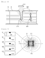
- the first leakage magnetic flux measurement unit 212 of the overall defect detection unit 210 may measure the strength of leakage magnetic flux. That is, as shown in FIG. 3 , when magnetic flux B is generated in the direction of transfer of the steel plate S, the first leakage magnetic flux measurement unit 212 may measure the strength of leakage magnetic flux 300 caused by a surface defect 310 and an internal defect 320. The measured strength of the leakage magnetic flux 300 may be transmitted to the first defect detection unit 213.
- the first defect detection unit 213 of the overall defect detection unit 210 may detect overall defects including the surface defect 310 and the internal defect 320 based on the strength of the measured leakage magnetic flux 300. For example, if the strength of the measured leakage magnetic flux 300 is greater than a certain value, the first defect detection unit 213 may determine that the steel plate S has an internal defect or a surface defect.
- the first defect detection unit 213 may provide first defect data about the positions of the overall defects in a detection region.
- the first defect detection unit 213 may generate first defect data about the positions of overall defects IDF and SDF in a detection region 510 and may transmit the first defect data to the data processing unit 230.
- points of the detection region 510 at which the overall defects IDF or SDF are present may be expressed using a binary number "1," and points of the detection region 510 at which the overall defects IDF and SDF are not present may be expressed using a binary number "0.”
- the surface defect detection unit 220 may detect surface defects based on the strength of leakage magnetic flux measured by generating magnetic flux in the thickness direction of the steel plate S through a detection region in which the overall defects detected by the overall defect detection unit 210 are located.
- the surface defect detection unit 220 may include second magnetizing units 221 and 223, second leakage magnetic flux measurement units 222 and 224, and a second defect detection unit 225.
- the second magnetizing units 221 and 223 of the surface defect detection unit 220 may generate magnetic flux B in the thickness direction of the steel plate S as shown in FIG. 4 .
- Electromagnets including cores 221a and 223a and coils 221b and 223b wound around the core 211a are illustrated as examples of the second magnetizing units 221 and 223.
- the second magnetizing units 221 and 223 are not limited thereto.
- permanent magnets may be used as the second magnetizing units 221 and 223.
- the second magnetizing units 221 and 223 may include: an upper magnetizing unit 221 disposed above the steel plate S to generate magnetic flux in the thickness direction of the steel plate S; and a lower magnetizing unit 223 disposed below the steel plate S to generate magnetic flux in the thickness direction of the steel plate S.
- the second leakage magnetic flux measurement units 222 and 224 of the surface defect detection unit 220 may measure the strength of leakage magnetic flux.
- the second leakage magnetic flux measurement units 222 and 224 may include: an upper leakage magnetic flux measurement unit 222 configured to measure the strength of leakage magnetic flux when magnetic flux generated by the upper magnetizing unit 221 passes through the steel plate S; and a lower leakage magnetic flux measurement unit 224 configured to measure the strength of leakage magnetic flux when magnetic flux generated by the lower magnetizing unit 223 passes through the steel plate S.
- the second magnetizing units 221 and 223 may generate magnetic flux in the thickness direction of the steel plate S, that is, in a direction perpendicular to the steel plate S, and the second leakage magnetic flux measurement units 222 and 224 may measure the strength of leakage magnetic flux when the magnetic flux generated in the thickness direction of the steel plate S passes through the steel plate S. If magnetic flux is generated in a direction (thickness direction) perpendicular to the plane of the steel plate S, the strength of leakage magnetic flux caused by surface defects of the steel plate S is higher than the strength of leakage magnetic flux caused by internal defects of the steel plate S, and thus surface defects may be easily detected based on only a measured degree of the strength of leakage magnetic flux.
- FIG. 4 is a view illustrating the positions of defects measured in the thickness direction of a steel plate S by the surface defect detection unit 220 illustrated in FIG. 2
- FIG. 5 is a views illustrating the strength of magnetic flux with respect to the positions of the defects illustrated in FIG. 4 .
- the horizontal axis refers to a leakage magnetic flux measurement region
- the vertical axis refers to the strength of leakage magnetic flux.
- the positions of defects are illustrated in the thickness direction (T) of the steel plate S.
- a defect DF1 (311) existing on an upper surface of the steel plate S, a defect DF3 (322) existing in a middle position of the steel plate S, a defect DF5 (312) existing on a lower surface of the steel plate S, a defect DF2 (321) existing between the defects DF1 and DF3, and a defect DF4 (323) existing between the defects DF3 and DF5 are illustrated.
- the second magnetizing units 221 and 223 may generate magnetic flux B in the thickness direction T of the steel plate S which is perpendicular to the surfaces of the steel plate S.
- magnetic flux is generated in the thickness direction T of the steel plate S which is perpendicular to the steel plate S, and thus surface defects may be easily detected based on only measured degrees of the strength of leakage magnetic flux.
- the second defect detection unit 225 of the surface defect detection unit 220 may detect surface defects of the steel plate S based on measured degrees of the strength of leakage magnetic flux.
- the second defect detection unit 225 may determine that the steel plate S has a surface defect.
- the second defect detection unit 225 may provide second defect data about the positions of surface defects in a detection region.
- the second defect detection unit 225 may generate second defect data about the positions of surface defects SDF in a detection region 520 and may transmit the second defect data to the data processing unit 230.
- points of the detection region 520 at which surface defects SDF are present may be expressed using a binary number "1," and points of the detection region 510 at which the surface defects SDF are not present may be expressed using a binary number "0.”
- the data processing unit 230 may detect only internal defects from a detection region by subtracting surface defects detected by the surface defect detection unit 220 from overall defects detected by the overall defect detection unit 210.
- the data processing unit 230 may detect only internal defects from a detection region 540 by subtracting second defect data about the detection region 520 received from the second defect detection unit 225 from first defect data about the detection region 510 received from the first defect detection unit 213 by using a subtracter 530.
- each of the first leakage magnetic flux measurement unit 212 and the second leakage magnetic flux measurement units 222 and 224 may be a differential magnetic sensor array including: a first magnetic sensor array having a plurality of magnetic sensors arranged in the width direction of a steel plate S so as to measure the strength of leakage magnetic flux; a second magnetic sensor array having a plurality of magnetic sensors separate from the first magnet sensor array by a predetermined distance in a direction of transfer of the steel plate S so as to measure the strength of leakage magnetic flux; and a differential amplifier amplifying the difference between the strength of leakage magnetic flux measured by the first magnetic sensor array and the strength of leakage magnetic flux measured by the second magnetic sensor array.
- each of the first leakage magnetic flux measurement unit 212 and the second leakage magnetic flux measurement units 222 and 224 is a differential magnetic sensor array, eddy current errors occurring when a steel plate S is moved in a direction of transfer may be compensated for, and thus a non-distorted degree of the strength of leakage magnetic flux may be measured.
- first leakage magnetic flux measurement unit 212 and the second leakage magnetic flux measurement units 222 and 224 may include at least one selected from a Hall sensor, a magneto resistive (MR) sensor, a giant magneto resistive (GMR) sensor, and a giant magneto impedance (GMI) sensor.
- MR magneto resistive
- GMR giant magneto resistive
- GMI giant magneto impedance
- overall defects including surface defects and internal defects are first detected from a predetermined detection region of a steel plate, and then the surface defects are independently detected from the detection region of the steel plate. Therefore, only the internal defects existing in the detection region may be detected by subtracting the independently detected surface defects from the overall defects.
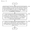
- FIG. 7 is a flowchart illustrating a method for detecting internal defects of a steel plate according to an exemplary embodiment of the present disclosure.
- FIGS. 1 to 7 the method for detecting defects of a steel plate will be described in detail with reference to FIGS. 1 to 7 according to the exemplary embodiment of the present disclosure. However, the same descriptions as those given above with reference to FIGS. 1 to 6 will not be repeated here for clarity.
- the overall defect detection unit 210 may detect overall defects including surface defects of a steel plate S and internal defects of the steel plate S based on the strength of leakage magnetic flux measured by generating magnetic flux in a direction of transfer of the steel plate S (S601).
- the first magnetizing unit 211 of the overall defect detection unit 210 may generate magnetic flux B in the direction of transfer of the steel plate S as shown in FIG. 3 .
- the first leakage magnetic flux measurement unit 212 of the overall defect detection unit 210 may measure the strength of leakage magnetic flux.
- the first defect detection unit 213 of the overall defect detection unit 210 may detect overall defects including surface defects such as a surface defect 310 and internal defects such as an internal defect 320 based on the strength of measured leakage magnetic flux 300.
- the surface defect detection unit 220 may detect the surface defects of the steel plate S based on the strength of leakage magnetic flux measured by generating magnetic flux in the thickness direction of the steel plate S through a detection region in which the overall defects detected by the overall defect detection unit 210 are located (S602).
- the second magnetizing units 221 and 223 of the surface defect detection unit 220 may generate magnetic flux B in the thickness direction of the steel plate S as shown in FIG. 4 .
- the second magnetizing units 221 and 223 may include: the upper magnetizing unit 221 disposed above the steel plate S to generate magnetic flux in the thickness direction of the steel plate S; and the lower magnetizing unit 223 disposed below the steel plate S to generate magnetic flux in the thickness direction of the steel plate S.
- the second leakage magnetic flux measurement units 222 and 224 of the surface defect detection unit 220 may measure the strength of leakage magnetic flux.
- the second leakage magnetic flux measurement units 222 and 224 may include: the upper leakage magnetic flux measurement unit 222 configured to measure the strength of leakage magnetic flux when magnetic flux generated by the upper magnetizing unit 221 passes through the steel plate S; and the lower leakage magnetic flux measurement unit 224 configured to measure the strength of leakage magnetic flux when magnetic flux generated by the lower magnetizing unit 223 passes through the steel plate S.
- the second defect detection unit 225 of the surface defect detection unit 220 may detect the surface defects of the steel plate S based on measured degrees of the strength of leakage magnetic flux.
- the data processing unit 230 may detect only the internal defects existing in the detection region by subtracting the surface defects detected by the surface defect detection unit 220 from the overall defects detected by the overall defect detection unit 210 (S603).
- the data processing unit 230 may detect only internal defects from a detection region 540 by subtracting second defect data about a detection region 520 received from the second defect detection unit 225 from first defect data about a detection region 510 received from the first defect detection unit 213 by using the subtracter 530.
- overall defects including surface defects and internal defects are first detected from a predetermined detection region of a steel plate, and the surface defects are independently detected from the detection region of the steel plate. Therefore, only the internal defects existing in the detection region may be detected by subtracting the independently detected surface defects from the overall defects.
Landscapes
- Chemical & Material Sciences (AREA)
- Health & Medical Sciences (AREA)
- Life Sciences & Earth Sciences (AREA)
- Immunology (AREA)
- Pathology (AREA)
- Physics & Mathematics (AREA)
- General Physics & Mathematics (AREA)
- General Health & Medical Sciences (AREA)
- Analytical Chemistry (AREA)
- Biochemistry (AREA)
- Chemical Kinetics & Catalysis (AREA)
- Electrochemistry (AREA)
- Engineering & Computer Science (AREA)
- Mechanical Engineering (AREA)
- Crystallography & Structural Chemistry (AREA)
- Food Science & Technology (AREA)
- Medicinal Chemistry (AREA)
- Investigating Or Analyzing Materials By The Use Of Magnetic Means (AREA)
Abstract
Description
- The present disclosure relates to a method for detecting internal defects of a steel plate.
- Examples of steel defect detection techniques include an ultrasonic testing method, a magnetic flux leakage inspection method, a magnetic particle inspection method, an eddy current inspection method, and an optical method.
- In the magnetic flux leakage inspection method, magnetic flux leakage from surfaces of a steel plate is measured using a magnetic sensor such as a Hall element capable of converting magnetic flux into an electric signal, and it is determined whether the steel plate has defects based on the measured magnetic flux leakage.
-
FIG. 1 illustrates an apparatus for detecting defects of a steel plate by the magnetic flux leakage inspection method. - Referring to
FIG. 1 , the steel plate defect detection apparatus may include: amagnetizing unit 110 generating magnetic flux in a direction of transfer of a steel plate S to magnetize the steel plate S; amagnetic sensor array 120 arranged along the width of the steel plate S for measuring leakage magnetic flux when magnetic flux passes through defects of the steel plate S; and an amplifyingunit 130 amplifying a signal output from themagnetic sensor array 120 according to leakage magnetic flux. Themagnetizing unit 110 may include a permanent magnet PM andyokes - However, when defects of the steel sheet S are detected using the steel plate defect detection apparatus, since the steel plate S is magnetized in a direction of transfer of the steel plate S, leakage magnetic flux measured using the
magnetic sensor array 120 contains information about defects existing on the surfaces of the steel plate S as well as defects existing inside the steel plate S. That is, it is difficult or impossible to detect only defects existing inside the steel plate S. - Aspects of the present disclosure may provide an apparatus and method for detecting only internal defects of a steel plate.
- According to an aspect of the present disclosure, an apparatus for detecting internal defects of a steel plate may include: an overall defect detection unit detecting overall defects of a steel plate including surface defects existing on surfaces of the steel plate and internal defects existing inside the steel plate based on a degree of strength of leakage magnetic flux measured by generating magnetic flux in a direction of transfer of the steel plate; a surface defect detection unit detecting the surface defects based on a degree of strength of leakage magnetic flux measured by generating magnetic flux in a thickness direction of the steel plate through a detection region in which the overall defects detected by the overall defect detection unit are located; and a data processing unit detecting only the internal defects existing in the detection region by subtracting the surface defects detected by the surface defect detection unit from the overall defects detected by the overall defect detection unit.
- In some embodiments of the present disclosure, the overall defect detection unit may include: a first magnetizing unit generating magnetic flux in the direction of transfer of the steel plate; a first leakage magnetic flux measurement unit measuring a degree of strength of leakage magnetic flux when the magnetic flux generated in the direction of transfer passes through the steel plate; and a first defect detection unit detecting the overall defects based on the measured degree of strength of leakage magnetic flux.
- In some embodiments of the present disclosure, the surface defect detection unit may include: a second magnetizing unit generating magnetic flux in the thickness direction of the steel plate; a second leakage magnetic flux measurement unit measuring a degree of strength of leakage magnetic flux when the magnetic flux generated in the thickness direction passes through the steel plate; and a second defect detection unit detecting the surface defects of the steel plate based on the measured degree of strength of leakage magnetic flux.
- In some embodiments of the present disclosure, the second magnetizing unit may include: an upper magnetizing unit disposed above the steel plate to generate magnetic flux in the thickness direction of the steel plate; and a lower magnetizing unit disposed below the steel plate to generate magnetic flux in the thickness direction of the steel plate, wherein the second leakage magnetic flux measurement unit may include: an upper leakage magnetic flux measurement unit measuring a degree of strength of leakage magnetic flux when the magnetic flux generated by the upper magnetizing unit passes through the steel plate; and a lower leakage magnetic flux measurement unit measuring a degree of strength of leakage magnetic flux when the magnetic flux generated by the lower magnetizing unit passes through the steel plate.
- In some embodiments of the present disclosure, the first defect detection unit may provide first defect data about positions of the overall defects detected in the detection region, the second defect detection unit may provide second defect data about positions of the surface defects detected in the detection region, and the data processing unit may detect only the internal defects existing in the detection region by subtracting the second defect data from the first defect data.
- In some embodiments of the present disclosure, the first defect data may express points of the detection region at which the overall defects are preset by using a binary number "1," and points of the detection region at which the overall defects are not present by using a binary number "0," and the second defect data may express points of the detection region at which the surface defects are present by using a binary number "1," and points of the detection region at which the surface defects are not present by using a binary number "0."
- In some embodiments of the present disclosure, each of the first and second leakage magnetic flux measurement units may include: a first magnetic sensor array including a plurality of magnetic sensors arranged in a width direction of the steel plate so as to measure a degree of strength of leakage magnetic flux; a second magnetic sensor array including a plurality of magnetic sensors separate from the first magnet sensor array by a predetermined distance in the direction of transfer of the steel plate so as to measure a degree of strength of leakage magnetic flux; and a differential amplifier amplifying a difference between the degree of strength of leakage magnetic flux measured by the first magnetic sensor array and the degree of strength of leakage magnetic flux measured by the second magnetic sensor array.
- In some embodiments of the present disclosure, the first and second leakage magnetic flux measurement units may include at least one selected from a Hall sensor, a magneto resistive (MR) sensor, a giant magneto resistive (GMR) sensor, and a giant magneto impedance (GMI) sensor.
- According to another aspect of the present disclosure, a method for detecting internal defects of a steel plate may include: detecting overall defects of a steel plate including surface defects existing on surfaces of the steel plate and internal defects existing inside the steel plate by using an overall defect detection unit based on a degree of strength of leakage magnetic flux measured by generating magnetic flux in a direction of transfer of the steel plate; detecting the surface defects by using a surface defect detection unit based on a degree of strength of leakage magnetic flux measured by generating magnetic flux in a thickness direction of the steel plate through a detection region in which the overall defects detected by the overall defect detection unit are located; and
detecting only the internal defects existing in the detection region by using a data processing unit by subtracting the surface defects detected by the surface defect detection unit from the overall defects detected by the overall defect detection unit. - In some embodiments of the present disclosure, the detecting of the overall defects may include: generating magnetic flux in the direction of transfer of the steel plate by using a first magnetizing unit; measuring a degree of strength of leakage magnetic flux by using a first leakage magnetic flux measurement unit when the magnetic flux generated in the direction of transfer passes through the steel plate; and detecting the overall defects by using a first defect detection unit based on the measured degree of strength of leakage magnetic flux.
- In some embodiments of the present disclosure, the detecting of the surface defect may include: generating magnetic flux in the thickness direction of the steel plate by using a second magnetizing unit; measuring a degree of strength of leakage magnetic flux by using a second leakage magnetic flux measurement unit when the magnetic flux generated in the thickness direction passes through the steel plate; and detecting the surface defects of the steel plate by using a second defect detection unit based on the measured degree of strength of leakage magnetic flux.
- In some embodiments of the present disclosure, the generating of the magnetic flux in the thickness direction of the steel plate may include: generating magnetic flux in the thickness direction of the steel plate by using an upper magnetizing unit of the second magnetizing unit; and generating magnetic flux in the thickness direction of the steel plate by using a lower magnetizing unit of the second magnetizing unit, wherein the measuring of the degree of strength of leakage magnetic flux by using the second leakage magnetic flux measurement unit may include: measuring a degree of strength of leakage magnetic flux by using an upper leakage magnetic flux measurement unit of the second leakage magnetic flux measurement unit when the magnetic flux generated by the upper magnetizing unit passes through the steel plate; and measuring a degree of strength of leakage magnetic flux by using a lower leakage magnetic flux measurement unit of the second leakage magnetic flux measurement unit when the magnetic flux generated by the lower magnetizing unit passes through the steel plate.
- In some embodiments of the present disclosure, the method may further include: providing first defect data regarding positions of the overall defects detected in the detection region by using the first defect detection unit; and providing second defect data about positions of the surface defects detected in the detection region by using the second defect detection unit, wherein the detecting of only the internal defects existing in the detection region may be performed by subtracting the second defect data from the first defect data using the data processing unit.
- In some embodiments of the present disclosure, the first defect data may express points of the detection region at which the overall defects are preset by using a binary number "1," and points of the detection region at which the overall defects are not present by using a binary number "0," and the second defect data may express points of the detection region at which the surface defects are present by using a binary number "1," and points of the detection region at which the surface defects are not present by using a binary number "0."
- In some embodiments of the present disclosure, each of the first and second leakage magnetic flux measurement units may include: a first magnetic sensor array including a plurality of magnetic sensors arranged in a width direction of the steel plate so as to measure a degree of strength of leakage magnetic flux; a second magnetic sensor array including a plurality of magnetic sensors separate from the first magnet sensor array by a predetermined distance in the direction of transfer of the steel plate so as to measure a degree of strength of leakage magnetic flux; and a differential amplifier amplifying a difference between the degree of strength of leakage magnetic flux measured by the first magnetic sensor array and the degree of strength of leakage magnetic flux measured by the second magnetic sensor array.
- In some embodiments of the present disclosure, the first and second leakage magnetic flux measurement units may include at least one selected from a Hall sensor, a magneto resistive (MR) sensor, a giant magneto resistive (GMR) sensor, and a giant magneto impedance (GMI) sensor.
- According to exemplary embodiments of the present disclosure, overall defects including surface defects and internal defects are first detected from a predetermined detection region of a steel plate, and then the surface defects are independently detected from the detection region of the steel plate. Thereafter, only the internal defects existing in the detection region may be detected by subtracting the independently detected surface defects from the overall defects.
-
-
FIG. 1 is a view illustrating an apparatus for detecting defects of a steel plate. -
FIG. 2 is a view illustrating an apparatus for detecting internal defects of a steel plate according to an exemplary embodiment of the present disclosure. -
FIG. 3 is a view illustrating a magnetizing direction of an overall defect detection unit illustrated inFIG. 2 and overall defects detected by the overall defect detection unit. -
FIG. 4 is a view illustrating the positions of defects detected in a thickness direction of a steel plate by a surface defect detection unit illustrated inFIG. 2 . -
FIG. 5 is a view illustrating the strength of magnetic flux with respect to the positions of the defects illustrated inFIG. 4 . -
FIG. 6 is a view illustrating how a data processing unit illustrated inFIG. 2 detects only internal defects. -
FIG. 7 is a flowchart illustrating a method for detecting internal defects of a steel plate according to an exemplary embodiment of the present disclosure. - Hereinafter, exemplary embodiments of the present disclosure will be described in detail with reference to the accompanying drawings. However, various changes in form and details may be made within the scope of the present invention, and the scope of the present invention is not limited to the exemplary embodiments described below. In the drawings, the shapes and dimensions of elements may be exaggerated for clarity, and like reference numerals denote like elements.
-
FIG. 2 is a view illustrating an apparatus for detecting internal defects of a steel plate according to an exemplary embodiment of the present disclosure.FIG. 3 is a view illustrating a magnetizing direction of an overalldefect detection unit 210 illustrated inFIG. 2 and overall defects detected by the overalldefect detection unit 210,FIG. 4 is a view illustrating the positions of defects detected in a thickness direction of a steel plate by a surfacedefect detection unit 220 illustrated inFIG. 2 , andFIG. 5 is a views illustrating the strength of magnetic flux with respect to the positions of the defects illustrated inFIG. 4 .FIG. 6 is a view illustrating how adata processing unit 230 illustrated inFIG. 2 detects only internal defects. - As illustrated in
FIG. 2 , the apparatus for detecting internal defects of a steel plate may include: the overalldefect detection unit 210 detecting overall defects including surface defects existing on the surfaces of a steel plate S and internal defects existing inside the steel plate S based on the strength of leakage magnetic flux measured by generating magnetic flux in a direction of transfer of the steel plate S; the surfacedefect detection unit 220 detecting the surface defects based on the strength of leakage magnetic flux measured by generating magnetic flux in a thickness direction of the steel plate S through a detection region in which the overall defects detected by the overalldefect detection unit 210 are located; and thedata processing unit 230 detecting only the internal defects existing in the detection region by subtracting the surface defects detected by the surfacedefect detection unit 220 from the overall defects detected by the overalldefect detection unit 210. - Hereinafter, the apparatus for detecting defects of a steel plate will be described in detail with reference to
FIGS. 2 to 6 according to the exemplary embodiment of the present disclosure. - Referring to
FIG. 2 , the overalldefect detection unit 210 may detect overall defects including surface defects of a the steel plate S and internal defects of the steel plate S based on the strength of leakage magnetic flux measured by generating magnetic flux in a direction of transfer of the steel plate S. - In detail, the overall
defect detection unit 210 may include a firstmagnetizing unit 211, a first leakage magneticflux measurement unit 212, and a firstdefect detection unit 213. - The first
magnetizing unit 211 of the overalldefect detection unit 210 may generate magnetic flux B in the direction of transfer of the steel plate S as shown inFIG. 3 . An electromagnet including acore 211a and acoil 211b wound around thecore 211a is illustrated as an example of the first magnetizingunit 211. However, the firstmagnetizing unit 211 is not limited thereto. For example, it will be apparent to those of ordinary skill in the art that a permanent magnet may be used as the firstmagnetizing unit 211. - When magnetic flux B generated in the direction of transfer of the steel plate S passes through the steel plate S, the first leakage magnetic
flux measurement unit 212 of the overalldefect detection unit 210 may measure the strength of leakage magnetic flux. That is, as shown inFIG. 3 , when magnetic flux B is generated in the direction of transfer of the steel plate S, the first leakage magneticflux measurement unit 212 may measure the strength of leakagemagnetic flux 300 caused by asurface defect 310 and aninternal defect 320. The measured strength of the leakagemagnetic flux 300 may be transmitted to the firstdefect detection unit 213. - The first
defect detection unit 213 of the overalldefect detection unit 210 may detect overall defects including thesurface defect 310 and theinternal defect 320 based on the strength of the measured leakagemagnetic flux 300. For example, if the strength of the measured leakagemagnetic flux 300 is greater than a certain value, the firstdefect detection unit 213 may determine that the steel plate S has an internal defect or a surface defect. - In addition, the first
defect detection unit 213 may provide first defect data about the positions of the overall defects in a detection region. - That is, as shown in
FIG. 6 , the firstdefect detection unit 213 may generate first defect data about the positions of overall defects IDF and SDF in adetection region 510 and may transmit the first defect data to thedata processing unit 230. In the first defect data, points of thedetection region 510 at which the overall defects IDF or SDF are present may be expressed using a binary number "1," and points of thedetection region 510 at which the overall defects IDF and SDF are not present may be expressed using a binary number "0." - The surface
defect detection unit 220 may detect surface defects based on the strength of leakage magnetic flux measured by generating magnetic flux in the thickness direction of the steel plate S through a detection region in which the overall defects detected by the overalldefect detection unit 210 are located. - In detail, the surface
defect detection unit 220 may include secondmagnetizing units flux measurement units defect detection unit 225. - The second magnetizing
units defect detection unit 220 may generate magnetic flux B in the thickness direction of the steel plate S as shown inFIG. 4 .Electromagnets including cores core 211a are illustrated as examples of the second magnetizingunits units units - The second magnetizing
units upper magnetizing unit 221 disposed above the steel plate S to generate magnetic flux in the thickness direction of the steel plate S; and alower magnetizing unit 223 disposed below the steel plate S to generate magnetic flux in the thickness direction of the steel plate S. - When magnetic flux B generated in the thickness direction of the steel plate S passes through the steel plate S, the second leakage magnetic
flux measurement units defect detection unit 220 may measure the strength of leakage magnetic flux. - The second leakage magnetic
flux measurement units flux measurement unit 222 configured to measure the strength of leakage magnetic flux when magnetic flux generated by the upper magnetizingunit 221 passes through the steel plate S; and a lower leakage magneticflux measurement unit 224 configured to measure the strength of leakage magnetic flux when magnetic flux generated by thelower magnetizing unit 223 passes through the steel plate S. - That is, according to the exemplary embodiment of the present disclosure, the second magnetizing
units flux measurement units - With reference to
FIGS. 4 and5 , the strength of leakage magnetic flux according to the positions of defects of a steel plate S will now be described in detail for the case in which magnetic flux is generated in a direction (thickness direction) perpendicular to the plane of the steel plate S. -
FIG. 4 is a view illustrating the positions of defects measured in the thickness direction of a steel plate S by the surfacedefect detection unit 220 illustrated inFIG. 2 , andFIG. 5 is a views illustrating the strength of magnetic flux with respect to the positions of the defects illustrated inFIG. 4 . InFIG. 5 , the horizontal axis refers to a leakage magnetic flux measurement region, and the vertical axis refers to the strength of leakage magnetic flux. - In
FIG. 4 , the positions of defects are illustrated in the thickness direction (T) of the steel plate S. A defect DF1 (311) existing on an upper surface of the steel plate S, a defect DF3 (322) existing in a middle position of the steel plate S, a defect DF5 (312) existing on a lower surface of the steel plate S, a defect DF2 (321) existing between the defects DF1 and DF3, and a defect DF4 (323) existing between the defects DF3 and DF5 are illustrated. According to the exemplary embodiment of the present disclosure, the second magnetizingunits - In this case, as illustrated (a) in
FIG. 5 in which degrees of strength of leakage magnetic flux measured by the upper leakage magneticflux measurement unit 222 are shown, the strength of leakage magnetic flux caused by the defect DF1 (311) existing on the upper surface of the steel plate S (refer to a curve 310) is much greater than the strength of leakage magnetic flux caused by any of the other defects DF2 to DF5 (refer tocurves - Similarly, as illustrated in (b)
FIG. 5 , in which degrees of strength of leakage magnetic flux measured by the lower leakage magneticflux measurement unit 224 are shown, the strength of leakage magnetic flux caused by the defect DF5 (312) existing on the lower surface of the steel plate S (refer to a curve 312) is much greater than the strength of leakage magnetic flux caused by any of the other defects DF1 to DF4 (refer tocurves - As described above, according to the exemplary embodiment of the present disclosure, magnetic flux is generated in the thickness direction T of the steel plate S which is perpendicular to the steel plate S, and thus surface defects may be easily detected based on only measured degrees of the strength of leakage magnetic flux.
- The second
defect detection unit 225 of the surfacedefect detection unit 220 may detect surface defects of the steel plate S based on measured degrees of the strength of leakage magnetic flux. - That is, if the strength of measured leakage magnetic flux is greater than a certain value, the second
defect detection unit 225 may determine that the steel plate S has a surface defect. - In addition, the second
defect detection unit 225 may provide second defect data about the positions of surface defects in a detection region. - That is, as shown in
FIG. 6 , the seconddefect detection unit 225 may generate second defect data about the positions of surface defects SDF in adetection region 520 and may transmit the second defect data to thedata processing unit 230. In the second defect data, points of thedetection region 520 at which surface defects SDF are present may be expressed using a binary number "1," and points of thedetection region 510 at which the surface defects SDF are not present may be expressed using a binary number "0." - The
data processing unit 230 may detect only internal defects from a detection region by subtracting surface defects detected by the surfacedefect detection unit 220 from overall defects detected by the overalldefect detection unit 210. - In detail, as shown in
FIG. 6 , thedata processing unit 230 may detect only internal defects from adetection region 540 by subtracting second defect data about thedetection region 520 received from the seconddefect detection unit 225 from first defect data about thedetection region 510 received from the firstdefect detection unit 213 by using asubtracter 530. - In
FIG. 6 , althoughdifferent reference numerals numerical references - For example, each of the first leakage magnetic
flux measurement unit 212 and the second leakage magneticflux measurement units - As described above, since each of the first leakage magnetic
flux measurement unit 212 and the second leakage magneticflux measurement units - In addition, the first leakage magnetic
flux measurement unit 212 and the second leakage magneticflux measurement units - As described above, according to the exemplary embodiment of the present disclosure, overall defects including surface defects and internal defects are first detected from a predetermined detection region of a steel plate, and then the surface defects are independently detected from the detection region of the steel plate. Therefore, only the internal defects existing in the detection region may be detected by subtracting the independently detected surface defects from the overall defects.
-
FIG. 7 is a flowchart illustrating a method for detecting internal defects of a steel plate according to an exemplary embodiment of the present disclosure. - Hereinafter, the method for detecting defects of a steel plate will be described in detail with reference to
FIGS. 1 to 7 according to the exemplary embodiment of the present disclosure. However, the same descriptions as those given above with reference toFIGS. 1 to 6 will not be repeated here for clarity. - Referring to
FIGS. 1 to 7 , the overalldefect detection unit 210 may detect overall defects including surface defects of a steel plate S and internal defects of the steel plate S based on the strength of leakage magnetic flux measured by generating magnetic flux in a direction of transfer of the steel plate S (S601). - In detail, the first magnetizing
unit 211 of the overalldefect detection unit 210 may generate magnetic flux B in the direction of transfer of the steel plate S as shown inFIG. 3 . - When the magnetic flux B generated in the direction of transfer of the steel plate S passes through the steel plate S, the first leakage magnetic
flux measurement unit 212 of the overalldefect detection unit 210 may measure the strength of leakage magnetic flux. - Then, the first
defect detection unit 213 of the overalldefect detection unit 210 may detect overall defects including surface defects such as asurface defect 310 and internal defects such as aninternal defect 320 based on the strength of measured leakagemagnetic flux 300. - Thereafter, the surface
defect detection unit 220 may detect the surface defects of the steel plate S based on the strength of leakage magnetic flux measured by generating magnetic flux in the thickness direction of the steel plate S through a detection region in which the overall defects detected by the overalldefect detection unit 210 are located (S602). - In detail, the second magnetizing
units defect detection unit 220 may generate magnetic flux B in the thickness direction of the steel plate S as shown inFIG. 4 . As described above, the second magnetizingunits unit 221 disposed above the steel plate S to generate magnetic flux in the thickness direction of the steel plate S; and thelower magnetizing unit 223 disposed below the steel plate S to generate magnetic flux in the thickness direction of the steel plate S. - When the magnetic flux B generated in the thickness direction of the steel plate S passes through the steel plate S, the second leakage magnetic
flux measurement units defect detection unit 220 may measure the strength of leakage magnetic flux. As described above, the second leakage magneticflux measurement units flux measurement unit 222 configured to measure the strength of leakage magnetic flux when magnetic flux generated by the upper magnetizingunit 221 passes through the steel plate S; and the lower leakage magneticflux measurement unit 224 configured to measure the strength of leakage magnetic flux when magnetic flux generated by thelower magnetizing unit 223 passes through the steel plate S. - Then, the second
defect detection unit 225 of the surfacedefect detection unit 220 may detect the surface defects of the steel plate S based on measured degrees of the strength of leakage magnetic flux. - Finally, the
data processing unit 230 may detect only the internal defects existing in the detection region by subtracting the surface defects detected by the surfacedefect detection unit 220 from the overall defects detected by the overall defect detection unit 210 (S603). - In detail, as shown in
FIG. 6 , thedata processing unit 230 may detect only internal defects from adetection region 540 by subtracting second defect data about adetection region 520 received from the seconddefect detection unit 225 from first defect data about adetection region 510 received from the firstdefect detection unit 213 by using thesubtracter 530. - As described above, according to the exemplary embodiment of the present disclosure, overall defects including surface defects and internal defects are first detected from a predetermined detection region of a steel plate, and the surface defects are independently detected from the detection region of the steel plate. Therefore, only the internal defects existing in the detection region may be detected by subtracting the independently detected surface defects from the overall defects.
- The scope of the present invention is not limited to the above-described exemplary embodiments and the accompanying drawings. The scope of the present invention is defined by the appended claims, and it will be apparent to those of ordinary skill in the art that substitutions, modifications, and variations could be made without departing from the scope of the present invention as defined by the appended claims.
Claims (14)
- An apparatus for detecting internal defects of a steel plate, the apparatus comprising:an overall defect detection unit detecting overall defects of a steel plate including surface defects existing on surfaces of the steel plate and internal defects existing inside the steel plate based on a degree of strength of leakage magnetic flux measured by generating magnetic flux in a direction of transfer of the steel plate;a surface defect detection unit detecting the surface defects based on a degree of strength of leakage magnetic flux measured by generating magnetic flux in a thickness direction of the steel plate through a detection region in which the overall defects detected by the overall defect detection unit are located; anda data processing unit detecting only the internal defects existing in the detection region by subtracting the surface defects detected by the surface defect detection unit from the overall defects detected by the overall defect detection unit.
- The apparatus of claim 1, wherein the overall defect detection unit comprises:a first magnetizing unit generating magnetic flux in the direction of transfer of the steel plate;a first leakage magnetic flux measurement unit measuring a degree of strength of leakage magnetic flux when the magnetic flux generated in the direction of transfer passes through the steel plate; anda first defect detection unit detecting the overall defects based on the measured degree of strength of leakage magnetic flux.
- The apparatus of claim 2, wherein the surface defect detection unit comprises:a second magnetizing unit generating magnetic flux in the thickness direction of the steel plate;a second leakage magnetic flux measurement unit measuring a degree of strength of leakage magnetic flux when the magnetic flux generated in the thickness direction passes through the steel plate; anda second defect detection unit detecting the surface defects of the steel plate based on the measured degree of strength of leakage magnetic flux.
- The apparatus of claim 3, wherein the second magnetizing unit comprises:an upper magnetizing unit disposed above the steel plate to generate magnetic flux in the thickness direction of the steel plate; anda lower magnetizing unit disposed below the steel plate to generate magnetic flux in the thickness direction of the steel plate,wherein the second leakage magnetic flux measurement unit comprises:an upper leakage magnetic flux measurement unit measuring a degree of strength of leakage magnetic flux when the magnetic flux generated by the upper magnetizing unit passes through the steel plate; anda lower leakage magnetic flux measurement unit measuring a degree of strength of leakage magnetic flux when the magnetic flux generated by the lower magnetizing unit passes through the steel plate.
- The apparatus of claim 3, wherein the first defect detection unit provides first defect data about positions of the overall defects detected in the detection region,
the second defect detection unit provides second defect data about positions of the surface defects detected in the detection region, and
the data processing unit detects only the internal defects existing in the detection region by subtracting the second defect data from the first defect data. - The apparatus of claim 5, wherein the first defect data expresses points of the detection region at which the overall defects are preset by using a binary number "1," and points of the detection region at which the overall defects are not present by using a binary number "0," and
the second defect data expresses points of the detection region at which the surface defects are present by using a binary number "1," and points of the detection region at which the surface defects are not present by using a binary number "0." - The apparatus of claim 3, wherein each of the first and second leakage magnetic flux measurement units comprises:a first magnetic sensor array comprising a plurality of magnetic sensors arranged in a width direction of the steel plate so as to measure a degree of strength of leakage magnetic flux;a second magnetic sensor array comprising a plurality of magnetic sensors separate from the first magnet sensor array by a predetermined distance in the direction of transfer of the steel plate so as to measure a degree of strength of leakage magnetic flux; anda differential amplifier amplifying a difference between the degree of strength of leakage magnetic flux measured by the first magnetic sensor array and the degree of strength of leakage magnetic flux measured by the second magnetic sensor array.
- The apparatus of claim 3, wherein the first and second leakage magnetic flux measurement units comprise at least one selected from a Hall sensor, a magneto resistive (MR) sensor, a giant magneto resistive (GMR) sensor, and a giant magneto impedance (GMI) sensor.
- A method for detecting internal defects of a steel plate, the method comprising:detecting overall defects of a steel plate including surface defects existing on surfaces of the steel plate and internal defects existing inside the steel plate by using an overall defect detection unit based on a degree of strength of leakage magnetic flux measured by generating magnetic flux in a direction of transfer of the steel plate;detecting the surface defects by using a surface defect detection unit based on a degree of strength of leakage magnetic flux measured by generating magnetic flux in a thickness direction of the steel plate through a detection region in which the overall defects detected by the overall defect detection unit are located; anddetecting only the internal defects existing in the detection region by using a data processing unit by subtracting the surface defects detected by the surface defect detection unit from the overall defects detected by the overall defect detection unit.
- The method of claim 9, wherein the detecting of the overall defects comprises:generating magnetic flux in the direction of transfer of the steel plate by using a first magnetizing unit;measuring a degree of strength of leakage magnetic flux by using a first leakage magnetic flux measurement unit when the magnetic flux generated in the direction of transfer passes through the steel plate; anddetecting the overall defects by using a first defect detection unit based on the measured degree of strength of leakage magnetic flux.
- The method of claim 10, wherein the detecting of the surface defect comprises:generating magnetic flux in the thickness direction of the steel plate by using a second magnetizing unit;measuring a degree of strength of leakage magnetic flux by using a second leakage magnetic flux measurement unit when the magnetic flux generated in the thickness direction passes through the steel plate; anddetecting the surface defects of the steel plate by using a second defect detection unit based on the measured degree of strength of leakage magnetic flux.
- The method of claim 11, wherein the generating of the magnetic flux in the thickness direction of the steel plate comprises:generating magnetic flux in the thickness direction of the steel plate by using an upper magnetizing unit of the second magnetizing unit; andgenerating magnetic flux in the thickness direction of the steel plate by using a lower magnetizing unit of the second magnetizing unit,wherein the measuring of the degree of strength of leakage magnetic flux by using the second leakage magnetic flux measurement unit comprises:measuring a degree of strength of leakage magnetic flux by using an upper leakage magnetic flux measurement unit of the second leakage magnetic flux measurement unit when the magnetic flux generated by the upper magnetizing unit passes through the steel plate; and
measuring a degree of strength of leakage magnetic flux by using a lower leakage magnetic flux measurement unit of the second leakage magnetic flux measurement unit when the magnetic flux generated by the lower magnetizing unit passes through the steel plate. - The method of claim 11, further comprising:providing first defect data regarding positions of the overall defects detected in the detection region by using the first defect detection unit; andproviding second defect data about positions of the surface defects detected in the detection region by using the second defect detection unit,wherein the detecting of only the internal defects existing in the detection region is performed by subtracting the second defect data from the first defect data using the data processing unit.
- The method of claim 13, wherein the first defect data expresses points of the detection region at which the overall defects are preset by using a binary number "1," and points of the detection region at which the overall defects are not present by using a binary number "0," and
the second defect data expresses points of the detection region at which the surface defects are present by using a binary number "1," and points of the detection region at which the surface defects are not present by using a binary number "0."
Applications Claiming Priority (2)
| Application Number | Priority Date | Filing Date | Title |
|---|---|---|---|
| KR20120154251A KR101482347B1 (en) | 2012-12-27 | 2012-12-27 | Apparatus and method of detecting inner defect of steel plate |
| PCT/KR2013/011993 WO2014104675A1 (en) | 2012-12-27 | 2013-12-23 | Apparatus and method for detecting inner defects of steel plate |
Publications (3)
| Publication Number | Publication Date |
|---|---|
| EP2940464A1 true EP2940464A1 (en) | 2015-11-04 |
| EP2940464A4 EP2940464A4 (en) | 2015-12-16 |
| EP2940464B1 EP2940464B1 (en) | 2021-08-18 |
Family
ID=51021654
Family Applications (1)
| Application Number | Title | Priority Date | Filing Date |
|---|---|---|---|
| EP13866752.2A Active EP2940464B1 (en) | 2012-12-27 | 2013-12-23 | Apparatus and method for detecting inner defects of steel plate |
Country Status (6)
| Country | Link |
|---|---|
| US (1) | US10677755B2 (en) |
| EP (1) | EP2940464B1 (en) |
| JP (1) | JP6060278B2 (en) |
| KR (1) | KR101482347B1 (en) |
| CN (1) | CN104903718B (en) |
| WO (1) | WO2014104675A1 (en) |
Cited By (2)
| Publication number | Priority date | Publication date | Assignee | Title |
|---|---|---|---|---|
| EP3081932A4 (en) * | 2013-12-11 | 2016-12-21 | Posco | APPARATUS AND METHOD FOR INSPECTING DEFECTS IN STEEL PLATE |
| WO2020088765A1 (en) * | 2018-10-31 | 2020-05-07 | Nov Downhole Eurasia Limited | Magnetic flux leakage testing device and associated method for identifying and differentiating defects in metallic plates |
Families Citing this family (15)
| Publication number | Priority date | Publication date | Assignee | Title |
|---|---|---|---|---|
| CN104820014B (en) * | 2015-04-09 | 2016-01-13 | 广东大鹏液化天然气有限公司 | A kind of simulative tube pipe magnet leakage detector is by the proving installation of performance and method and purposes |
| US11009484B1 (en) | 2016-03-11 | 2021-05-18 | The University Of Tulsa | Velocity independent two-component magnetic flux leakage detective system |
| JP6681069B2 (en) * | 2016-10-24 | 2020-04-15 | 国立大学法人 岡山大学 | Magnetic nondestructive inspection method and magnetic nondestructive inspection apparatus |
| US10393702B2 (en) * | 2016-11-02 | 2019-08-27 | Weatherford Technology Holdings, Llc | Defect penetration estimate using magnetic flux image enhancement |
| DE102016124522A1 (en) * | 2016-12-15 | 2018-06-21 | Thyssenkrupp Ag | Method of inspecting a steel strip |
| CN107273573B (en) * | 2017-05-16 | 2020-09-18 | 电子科技大学 | Magnetic flux leakage simulation method based on loop current |
| JP7048028B2 (en) * | 2017-09-27 | 2022-04-05 | 日立造船株式会社 | Eddy current flaw detection system and eddy current flaw detection method |
| TWI663395B (en) * | 2018-11-02 | 2019-06-21 | 中國鋼鐵股份有限公司 | Steel strip crease detection method |
| CN109765503B (en) * | 2019-02-01 | 2021-03-30 | 昆山国显光电有限公司 | Processing chamber with fragment detection function and fragment detection method |
| CN110243924A (en) * | 2019-07-03 | 2019-09-17 | 西红柿科技(武汉)有限公司 | A kind of storage tank bottom plate intelligent detecting method |
| KR102326685B1 (en) * | 2019-12-20 | 2021-11-17 | 주식회사 포스코 | Apparatus and Method for Sensing Quality of Steel Plate Surface |
| CN111579637B (en) * | 2020-06-11 | 2022-04-29 | 哈尔滨工业大学(深圳)(哈尔滨工业大学深圳科技创新研究院) | A non-destructive testing method and device for detecting and distinguishing internal and external defects of wire ropes |
| KR102403603B1 (en) * | 2020-11-30 | 2022-05-31 | (주)엔키아 | Sensor data collection method and system using data and control channels |
| CN113406294B (en) * | 2021-06-30 | 2022-02-18 | 江苏汉诺威铸业有限公司 | Metal casting surface detection equipment |
| JPWO2025009207A1 (en) * | 2023-07-03 | 2025-01-09 |
Family Cites Families (26)
| Publication number | Priority date | Publication date | Assignee | Title |
|---|---|---|---|---|
| US4146837A (en) * | 1977-04-26 | 1979-03-27 | Irkutsky Filial Vsesojuznogo Nauchnoissledovatelskogo I Proektnogo Instituta Aluuminievoi Magnieovi I Elektrodonoi Promyshlennosti | Apparatus for detecting and recording surface and internal flaws |
| US4602212A (en) * | 1982-06-14 | 1986-07-22 | Sumitomo Metal Industries, Ltd. | Method and apparatus including a flux leakage and eddy current sensor for detecting surface flaws in metal products |
| JPS62226054A (en) * | 1986-03-28 | 1987-10-05 | Nippon Steel Corp | Discriminating device for defect of round steel |
| JPH0711508B2 (en) | 1987-03-10 | 1995-02-08 | 住友金属工業株式会社 | Leakage magnetic flux flaw detection method |
| US5485082A (en) * | 1990-04-11 | 1996-01-16 | Micro-Epsilon Messtechnik Gmbh & Co. Kg | Method of calibrating a thickness measuring device and device for measuring or monitoring the thickness of layers, tapes, foils, and the like |
| JPH04279856A (en) * | 1991-03-07 | 1992-10-05 | Sumitomo Metal Ind Ltd | Flaw detector |
| CA2088918C (en) * | 1991-06-04 | 1996-07-02 | Seigo Ando | Magnetic detecting method and apparatus therefor |
| JPH0763699A (en) * | 1993-08-30 | 1995-03-10 | Sumitomo Metal Ind Ltd | Defect inspection equipment |
| US5659248A (en) * | 1994-10-17 | 1997-08-19 | General Electric Company | Multilayer eddy current probe array for complete coverage of an inspection surface without mechanical scanning |
| US6285183B1 (en) * | 1996-09-30 | 2001-09-04 | Mcdonnell Douglas Corporation | Method and system for measuring the volume loss of a metal substrate |
| US6429650B1 (en) * | 1999-03-17 | 2002-08-06 | Southwest Research Institute | Method and apparatus generating and detecting torsional wave inspection of pipes or tubes |
| JP3606439B2 (en) | 2000-01-11 | 2005-01-05 | Jfeスチール株式会社 | Magnetic flux leakage inspection method |
| WO2002004937A1 (en) | 2000-07-12 | 2002-01-17 | Nkk Corporation | Magnetic leakage flux flaw detection method and manufacturing method of hot rolled steel plate using the same |
| US6933718B2 (en) * | 2001-06-12 | 2005-08-23 | The Boeing Company | Quantification method and system for corrosion and damage assessment |
| JP2003322622A (en) * | 2002-05-07 | 2003-11-14 | Jfe Steel Kk | Defect inspection apparatus and defect inspection method using the same |
| JP2004037216A (en) * | 2002-07-03 | 2004-02-05 | Jfe Steel Kk | Leakage magnetic flux detection method |
| US7626383B1 (en) * | 2005-04-25 | 2009-12-01 | Innovative Materials Testing Technologies, Inc. | Apparatus and method for holding a rotatable eddy-current magnetic probe, and for rotating the probe around a boundary |
| JP4279856B2 (en) | 2006-07-18 | 2009-06-17 | レノボ・シンガポール・プライベート・リミテッド | Information transfer method and computer |
| JP2008151744A (en) | 2006-12-20 | 2008-07-03 | Toshiba Corp | Steel sheet inspection system |
| JP5453861B2 (en) * | 2008-03-31 | 2014-03-26 | Jfeスチール株式会社 | Periodic defect detection apparatus and method |
| DE102008020194A1 (en) * | 2008-04-16 | 2009-10-22 | Institut Dr. Foerster Gmbh & Co. Kg | Method and device for detecting near-surface defects by means of leakage flux measurement |
| KR101091343B1 (en) * | 2008-12-26 | 2011-12-07 | 주식회사 포스코 | Flaw flaw detection method and apparatus of steel sheet |
| KR101085563B1 (en) | 2009-09-04 | 2011-11-25 | 조선대학교산학협력단 | Inclusion apparatus of cold rolled steel plate using magnetic sensor |
| JP5614312B2 (en) * | 2011-02-01 | 2014-10-29 | Jfeスチール株式会社 | Periodic defect detection method and periodic defect detection apparatus |
| JP4756409B1 (en) * | 2011-02-18 | 2011-08-24 | 大日機械工業株式会社 | Nondestructive inspection apparatus and nondestructive inspection method using alternating magnetic field |
| KR101309966B1 (en) | 2011-12-15 | 2013-09-17 | 주식회사 포스코 | Apparatus for detecting defect of steel plate |
-
2012
- 2012-12-27 KR KR20120154251A patent/KR101482347B1/en active Active
-
2013
- 2013-12-23 US US14/652,086 patent/US10677755B2/en active Active
- 2013-12-23 WO PCT/KR2013/011993 patent/WO2014104675A1/en not_active Ceased
- 2013-12-23 EP EP13866752.2A patent/EP2940464B1/en active Active
- 2013-12-23 CN CN201380068387.8A patent/CN104903718B/en active Active
- 2013-12-23 JP JP2015550306A patent/JP6060278B2/en active Active
Cited By (3)
| Publication number | Priority date | Publication date | Assignee | Title |
|---|---|---|---|---|
| EP3081932A4 (en) * | 2013-12-11 | 2016-12-21 | Posco | APPARATUS AND METHOD FOR INSPECTING DEFECTS IN STEEL PLATE |
| US10088453B2 (en) | 2013-12-11 | 2018-10-02 | Posco | Apparatus and method of detecting defect of steel plate |
| WO2020088765A1 (en) * | 2018-10-31 | 2020-05-07 | Nov Downhole Eurasia Limited | Magnetic flux leakage testing device and associated method for identifying and differentiating defects in metallic plates |
Also Published As
| Publication number | Publication date |
|---|---|
| JP6060278B2 (en) | 2017-01-11 |
| EP2940464B1 (en) | 2021-08-18 |
| KR20140084608A (en) | 2014-07-07 |
| CN104903718A (en) | 2015-09-09 |
| WO2014104675A1 (en) | 2014-07-03 |
| CN104903718B (en) | 2018-07-10 |
| US10677755B2 (en) | 2020-06-09 |
| EP2940464A4 (en) | 2015-12-16 |
| JP2016506523A (en) | 2016-03-03 |
| KR101482347B1 (en) | 2015-01-13 |
| US20150316508A1 (en) | 2015-11-05 |
Similar Documents
| Publication | Publication Date | Title |
|---|---|---|
| EP2940464B1 (en) | Apparatus and method for detecting inner defects of steel plate | |
| KR102501069B1 (en) | Flaw measurement method, defect measurement device and inspection probe | |
| EP2506003B1 (en) | Methods And Apparatus For The Inspection Of Plates And Pipe Walls | |
| CN106814131B (en) | Magnetic emission detection method and magnetic emission detection system for shallow damage of ferromagnetic planar components | |
| JP6051229B2 (en) | Steel sheet flaw detector | |
| KR20150048141A (en) | Eddy current flaw detection probe and eddy current flaw inspection apparatus | |
| CN103499636A (en) | Method for nondestructively testing micro-defects in sheet ferromagnetic materials based on measurement of magnetostatic force | |
| Kim et al. | A study on the measurement of axial cracks in the magnetic flux leakage NDT system | |
| KR101364684B1 (en) | Unit for Detecting Magnetic Leakage Flux Using Electromagnetic Induction and Non-destructive Testing System and Method Using th Same | |
| JP5851783B2 (en) | Eddy current testing probe | |
| JP2014202483A (en) | Inspection equipment and inspection method | |
| JP6296851B2 (en) | Defect depth estimation method and defect depth estimation apparatus | |
| JP6248201B2 (en) | Steel plate defect inspection apparatus and method | |
| US9726639B1 (en) | Apparatus for detecting magnetic flux leakage and methods of making and using same | |
| JP2017520849A (en) | Coin detection system | |
| KR101482346B1 (en) | Apparatus and method of detecting surface defect of steel plate | |
| CN104792859B (en) | A kind of local micro- magnetization detection means of yoke formula suitable for line style defect | |
| JP5721475B2 (en) | Interpolation probe for eddy current testing of ferromagnetic steel tubes | |
| JP2015078942A (en) | Magnetic flux leakage inspection device | |
| CN110779981A (en) | Ferromagnetic pipeline small defect magnetic detection sensor | |
| JP6580350B2 (en) | Hardened layer depth measuring device |
Legal Events
| Date | Code | Title | Description |
|---|---|---|---|
| PUAI | Public reference made under article 153(3) epc to a published international application that has entered the european phase |
Free format text: ORIGINAL CODE: 0009012 |
|
| 17P | Request for examination filed |
Effective date: 20150625 |
|
| AK | Designated contracting states |
Kind code of ref document: A1 Designated state(s): AL AT BE BG CH CY CZ DE DK EE ES FI FR GB GR HR HU IE IS IT LI LT LU LV MC MK MT NL NO PL PT RO RS SE SI SK SM TR |
|
| AX | Request for extension of the european patent |
Extension state: BA ME |
|
| A4 | Supplementary search report drawn up and despatched |
Effective date: 20151112 |
|
| RIC1 | Information provided on ipc code assigned before grant |
Ipc: G01N 27/83 20060101AFI20151106BHEP Ipc: G01N 33/20 20060101ALI20151106BHEP Ipc: B21B 38/00 20060101ALI20151106BHEP |
|
| RIN1 | Information on inventor provided before grant (corrected) |
Inventor name: CHOI, SANG-WOO Inventor name: CHOI, SE-HO Inventor name: BAE, HO-MOON Inventor name: YUN, JONG-PIL Inventor name: LEE, JU-SEUNG |
|
| DAX | Request for extension of the european patent (deleted) | ||
| STAA | Information on the status of an ep patent application or granted ep patent |
Free format text: STATUS: EXAMINATION IS IN PROGRESS |
|
| 17Q | First examination report despatched |
Effective date: 20191113 |
|
| REG | Reference to a national code |
Ref country code: DE Ref legal event code: R079 Ref document number: 602013078889 Country of ref document: DE Free format text: PREVIOUS MAIN CLASS: G01N0027820000 Ipc: B21B0038000000 |
|
| GRAP | Despatch of communication of intention to grant a patent |
Free format text: ORIGINAL CODE: EPIDOSNIGR1 |
|
| STAA | Information on the status of an ep patent application or granted ep patent |
Free format text: STATUS: GRANT OF PATENT IS INTENDED |
|
| RIC1 | Information provided on ipc code assigned before grant |
Ipc: B21B 38/00 20060101AFI20210301BHEP Ipc: G01N 27/83 20060101ALI20210301BHEP |
|
| INTG | Intention to grant announced |
Effective date: 20210318 |
|
| GRAS | Grant fee paid |
Free format text: ORIGINAL CODE: EPIDOSNIGR3 |
|
| GRAA | (expected) grant |
Free format text: ORIGINAL CODE: 0009210 |
|
| STAA | Information on the status of an ep patent application or granted ep patent |
Free format text: STATUS: THE PATENT HAS BEEN GRANTED |
|
| AK | Designated contracting states |
Kind code of ref document: B1 Designated state(s): AL AT BE BG CH CY CZ DE DK EE ES FI FR GB GR HR HU IE IS IT LI LT LU LV MC MK MT NL NO PL PT RO RS SE SI SK SM TR |
|
| REG | Reference to a national code |
Ref country code: GB Ref legal event code: FG4D |
|
| REG | Reference to a national code |
Ref country code: CH Ref legal event code: EP |
|
| REG | Reference to a national code |
Ref country code: DE Ref legal event code: R096 Ref document number: 602013078889 Country of ref document: DE |
|
| REG | Reference to a national code |
Ref country code: IE Ref legal event code: FG4D Ref country code: AT Ref legal event code: REF Ref document number: 1421148 Country of ref document: AT Kind code of ref document: T Effective date: 20210915 |
|
| REG | Reference to a national code |
Ref country code: LT Ref legal event code: MG9D |
|
| REG | Reference to a national code |
Ref country code: NL Ref legal event code: MP Effective date: 20210818 |
|
| REG | Reference to a national code |
Ref country code: AT Ref legal event code: MK05 Ref document number: 1421148 Country of ref document: AT Kind code of ref document: T Effective date: 20210818 |
|
| PG25 | Lapsed in a contracting state [announced via postgrant information from national office to epo] |
Ref country code: SE Free format text: LAPSE BECAUSE OF FAILURE TO SUBMIT A TRANSLATION OF THE DESCRIPTION OR TO PAY THE FEE WITHIN THE PRESCRIBED TIME-LIMIT Effective date: 20210818 Ref country code: RS Free format text: LAPSE BECAUSE OF FAILURE TO SUBMIT A TRANSLATION OF THE DESCRIPTION OR TO PAY THE FEE WITHIN THE PRESCRIBED TIME-LIMIT Effective date: 20210818 Ref country code: HR Free format text: LAPSE BECAUSE OF FAILURE TO SUBMIT A TRANSLATION OF THE DESCRIPTION OR TO PAY THE FEE WITHIN THE PRESCRIBED TIME-LIMIT Effective date: 20210818 Ref country code: BG Free format text: LAPSE BECAUSE OF FAILURE TO SUBMIT A TRANSLATION OF THE DESCRIPTION OR TO PAY THE FEE WITHIN THE PRESCRIBED TIME-LIMIT Effective date: 20211118 Ref country code: AT Free format text: LAPSE BECAUSE OF FAILURE TO SUBMIT A TRANSLATION OF THE DESCRIPTION OR TO PAY THE FEE WITHIN THE PRESCRIBED TIME-LIMIT Effective date: 20210818 Ref country code: LT Free format text: LAPSE BECAUSE OF FAILURE TO SUBMIT A TRANSLATION OF THE DESCRIPTION OR TO PAY THE FEE WITHIN THE PRESCRIBED TIME-LIMIT Effective date: 20210818 Ref country code: NO Free format text: LAPSE BECAUSE OF FAILURE TO SUBMIT A TRANSLATION OF THE DESCRIPTION OR TO PAY THE FEE WITHIN THE PRESCRIBED TIME-LIMIT Effective date: 20211118 Ref country code: PT Free format text: LAPSE BECAUSE OF FAILURE TO SUBMIT A TRANSLATION OF THE DESCRIPTION OR TO PAY THE FEE WITHIN THE PRESCRIBED TIME-LIMIT Effective date: 20211220 Ref country code: FI Free format text: LAPSE BECAUSE OF FAILURE TO SUBMIT A TRANSLATION OF THE DESCRIPTION OR TO PAY THE FEE WITHIN THE PRESCRIBED TIME-LIMIT Effective date: 20210818 Ref country code: ES Free format text: LAPSE BECAUSE OF FAILURE TO SUBMIT A TRANSLATION OF THE DESCRIPTION OR TO PAY THE FEE WITHIN THE PRESCRIBED TIME-LIMIT Effective date: 20210818 |
|
| PG25 | Lapsed in a contracting state [announced via postgrant information from national office to epo] |
Ref country code: PL Free format text: LAPSE BECAUSE OF FAILURE TO SUBMIT A TRANSLATION OF THE DESCRIPTION OR TO PAY THE FEE WITHIN THE PRESCRIBED TIME-LIMIT Effective date: 20210818 Ref country code: LV Free format text: LAPSE BECAUSE OF FAILURE TO SUBMIT A TRANSLATION OF THE DESCRIPTION OR TO PAY THE FEE WITHIN THE PRESCRIBED TIME-LIMIT Effective date: 20210818 Ref country code: GR Free format text: LAPSE BECAUSE OF FAILURE TO SUBMIT A TRANSLATION OF THE DESCRIPTION OR TO PAY THE FEE WITHIN THE PRESCRIBED TIME-LIMIT Effective date: 20211119 |
|
| PG25 | Lapsed in a contracting state [announced via postgrant information from national office to epo] |
Ref country code: NL Free format text: LAPSE BECAUSE OF FAILURE TO SUBMIT A TRANSLATION OF THE DESCRIPTION OR TO PAY THE FEE WITHIN THE PRESCRIBED TIME-LIMIT Effective date: 20210818 |
|
| PG25 | Lapsed in a contracting state [announced via postgrant information from national office to epo] |
Ref country code: DK Free format text: LAPSE BECAUSE OF FAILURE TO SUBMIT A TRANSLATION OF THE DESCRIPTION OR TO PAY THE FEE WITHIN THE PRESCRIBED TIME-LIMIT Effective date: 20210818 |
|
| REG | Reference to a national code |
Ref country code: DE Ref legal event code: R097 Ref document number: 602013078889 Country of ref document: DE |
|
| PG25 | Lapsed in a contracting state [announced via postgrant information from national office to epo] |
Ref country code: SM Free format text: LAPSE BECAUSE OF FAILURE TO SUBMIT A TRANSLATION OF THE DESCRIPTION OR TO PAY THE FEE WITHIN THE PRESCRIBED TIME-LIMIT Effective date: 20210818 Ref country code: SK Free format text: LAPSE BECAUSE OF FAILURE TO SUBMIT A TRANSLATION OF THE DESCRIPTION OR TO PAY THE FEE WITHIN THE PRESCRIBED TIME-LIMIT Effective date: 20210818 Ref country code: RO Free format text: LAPSE BECAUSE OF FAILURE TO SUBMIT A TRANSLATION OF THE DESCRIPTION OR TO PAY THE FEE WITHIN THE PRESCRIBED TIME-LIMIT Effective date: 20210818 Ref country code: EE Free format text: LAPSE BECAUSE OF FAILURE TO SUBMIT A TRANSLATION OF THE DESCRIPTION OR TO PAY THE FEE WITHIN THE PRESCRIBED TIME-LIMIT Effective date: 20210818 Ref country code: CZ Free format text: LAPSE BECAUSE OF FAILURE TO SUBMIT A TRANSLATION OF THE DESCRIPTION OR TO PAY THE FEE WITHIN THE PRESCRIBED TIME-LIMIT Effective date: 20210818 Ref country code: AL Free format text: LAPSE BECAUSE OF FAILURE TO SUBMIT A TRANSLATION OF THE DESCRIPTION OR TO PAY THE FEE WITHIN THE PRESCRIBED TIME-LIMIT Effective date: 20210818 |
|
| PLBE | No opposition filed within time limit |
Free format text: ORIGINAL CODE: 0009261 |
|
| STAA | Information on the status of an ep patent application or granted ep patent |
Free format text: STATUS: NO OPPOSITION FILED WITHIN TIME LIMIT |
|
| 26N | No opposition filed |
Effective date: 20220519 |
|
| PG25 | Lapsed in a contracting state [announced via postgrant information from national office to epo] |
Ref country code: MC Free format text: LAPSE BECAUSE OF FAILURE TO SUBMIT A TRANSLATION OF THE DESCRIPTION OR TO PAY THE FEE WITHIN THE PRESCRIBED TIME-LIMIT Effective date: 20210818 Ref country code: IT Free format text: LAPSE BECAUSE OF FAILURE TO SUBMIT A TRANSLATION OF THE DESCRIPTION OR TO PAY THE FEE WITHIN THE PRESCRIBED TIME-LIMIT Effective date: 20210818 |
|
| REG | Reference to a national code |
Ref country code: CH Ref legal event code: PL |
|
| GBPC | Gb: european patent ceased through non-payment of renewal fee |
Effective date: 20211223 |
|
| PG25 | Lapsed in a contracting state [announced via postgrant information from national office to epo] |
Ref country code: SI Free format text: LAPSE BECAUSE OF FAILURE TO SUBMIT A TRANSLATION OF THE DESCRIPTION OR TO PAY THE FEE WITHIN THE PRESCRIBED TIME-LIMIT Effective date: 20210818 |
|
| REG | Reference to a national code |
Ref country code: DE Ref legal event code: R081 Ref document number: 602013078889 Country of ref document: DE Owner name: POSCO CO., LTD, POHANG-SI, KR Free format text: FORMER OWNER: POSCO, POHANG-SI, GYEONGSANGBUK-DO, KR Ref country code: DE Ref legal event code: R081 Ref document number: 602013078889 Country of ref document: DE Owner name: POSCO CO., LTD, POHANG- SI, KR Free format text: FORMER OWNER: POSCO, POHANG-SI, GYEONGSANGBUK-DO, KR Ref country code: DE Ref legal event code: R081 Ref document number: 602013078889 Country of ref document: DE Owner name: POSCO HOLDINGS INC., KR Free format text: FORMER OWNER: POSCO, POHANG-SI, GYEONGSANGBUK-DO, KR |
|
| REG | Reference to a national code |
Ref country code: BE Ref legal event code: MM Effective date: 20211231 |
|
| PG25 | Lapsed in a contracting state [announced via postgrant information from national office to epo] |
Ref country code: LU Free format text: LAPSE BECAUSE OF NON-PAYMENT OF DUE FEES Effective date: 20211223 Ref country code: IE Free format text: LAPSE BECAUSE OF NON-PAYMENT OF DUE FEES Effective date: 20211223 Ref country code: GB Free format text: LAPSE BECAUSE OF NON-PAYMENT OF DUE FEES Effective date: 20211223 |
|
| PG25 | Lapsed in a contracting state [announced via postgrant information from national office to epo] |
Ref country code: BE Free format text: LAPSE BECAUSE OF NON-PAYMENT OF DUE FEES Effective date: 20211231 |
|
| PG25 | Lapsed in a contracting state [announced via postgrant information from national office to epo] |
Ref country code: LI Free format text: LAPSE BECAUSE OF NON-PAYMENT OF DUE FEES Effective date: 20211231 Ref country code: CH Free format text: LAPSE BECAUSE OF NON-PAYMENT OF DUE FEES Effective date: 20211231 |
|
| REG | Reference to a national code |
Ref country code: DE Ref legal event code: R081 Ref document number: 602013078889 Country of ref document: DE Owner name: POSCO CO., LTD, POHANG-SI, KR Free format text: FORMER OWNER: POSCO HOLDINGS INC., SEOUL, KR Ref country code: DE Ref legal event code: R081 Ref document number: 602013078889 Country of ref document: DE Owner name: POSCO CO., LTD, POHANG- SI, KR Free format text: FORMER OWNER: POSCO HOLDINGS INC., SEOUL, KR |
|
| PG25 | Lapsed in a contracting state [announced via postgrant information from national office to epo] |
Ref country code: HU Free format text: LAPSE BECAUSE OF FAILURE TO SUBMIT A TRANSLATION OF THE DESCRIPTION OR TO PAY THE FEE WITHIN THE PRESCRIBED TIME-LIMIT; INVALID AB INITIO Effective date: 20131223 |
|
| PG25 | Lapsed in a contracting state [announced via postgrant information from national office to epo] |
Ref country code: CY Free format text: LAPSE BECAUSE OF FAILURE TO SUBMIT A TRANSLATION OF THE DESCRIPTION OR TO PAY THE FEE WITHIN THE PRESCRIBED TIME-LIMIT Effective date: 20210818 |
|
| PG25 | Lapsed in a contracting state [announced via postgrant information from national office to epo] |
Ref country code: MK Free format text: LAPSE BECAUSE OF FAILURE TO SUBMIT A TRANSLATION OF THE DESCRIPTION OR TO PAY THE FEE WITHIN THE PRESCRIBED TIME-LIMIT Effective date: 20210818 |
|
| PG25 | Lapsed in a contracting state [announced via postgrant information from national office to epo] |
Ref country code: MT Free format text: LAPSE BECAUSE OF FAILURE TO SUBMIT A TRANSLATION OF THE DESCRIPTION OR TO PAY THE FEE WITHIN THE PRESCRIBED TIME-LIMIT Effective date: 20210818 |
|
| PGFP | Annual fee paid to national office [announced via postgrant information from national office to epo] |
Ref country code: FR Payment date: 20250925 Year of fee payment: 13 |
|
| PG25 | Lapsed in a contracting state [announced via postgrant information from national office to epo] |
Ref country code: TR Free format text: LAPSE BECAUSE OF FAILURE TO SUBMIT A TRANSLATION OF THE DESCRIPTION OR TO PAY THE FEE WITHIN THE PRESCRIBED TIME-LIMIT Effective date: 20210818 |
|
| PGFP | Annual fee paid to national office [announced via postgrant information from national office to epo] |
Ref country code: DE Payment date: 20250922 Year of fee payment: 13 |