EP2940262A1 - Oil circulation structure in internal combustion engine - Google Patents
Oil circulation structure in internal combustion engine Download PDFInfo
- Publication number
- EP2940262A1 EP2940262A1 EP15164064.6A EP15164064A EP2940262A1 EP 2940262 A1 EP2940262 A1 EP 2940262A1 EP 15164064 A EP15164064 A EP 15164064A EP 2940262 A1 EP2940262 A1 EP 2940262A1
- Authority
- EP
- European Patent Office
- Prior art keywords
- oil
- oil hole
- hole
- cylinder
- receiving portion
- Prior art date
- Legal status (The legal status is an assumption and is not a legal conclusion. Google has not performed a legal analysis and makes no representation as to the accuracy of the status listed.)
- Withdrawn
Links
- 238000002485 combustion reaction Methods 0.000 title claims description 19
- XLYOFNOQVPJJNP-UHFFFAOYSA-N water Substances O XLYOFNOQVPJJNP-UHFFFAOYSA-N 0.000 claims description 14
- 230000002093 peripheral effect Effects 0.000 claims description 12
- 239000007789 gas Substances 0.000 description 15
- 239000000498 cooling water Substances 0.000 description 9
- 230000005540 biological transmission Effects 0.000 description 2
- 230000000694 effects Effects 0.000 description 2
- 230000000452 restraining effect Effects 0.000 description 1
Images
Classifications
-
- F—MECHANICAL ENGINEERING; LIGHTING; HEATING; WEAPONS; BLASTING
- F01—MACHINES OR ENGINES IN GENERAL; ENGINE PLANTS IN GENERAL; STEAM ENGINES
- F01M—LUBRICATING OF MACHINES OR ENGINES IN GENERAL; LUBRICATING INTERNAL COMBUSTION ENGINES; CRANKCASE VENTILATING
- F01M11/00—Component parts, details or accessories, not provided for in, or of interest apart from, groups F01M1/00 - F01M9/00
- F01M11/02—Arrangements of lubricant conduits
-
- F—MECHANICAL ENGINEERING; LIGHTING; HEATING; WEAPONS; BLASTING
- F02—COMBUSTION ENGINES; HOT-GAS OR COMBUSTION-PRODUCT ENGINE PLANTS
- F02F—CYLINDERS, PISTONS OR CASINGS, FOR COMBUSTION ENGINES; ARRANGEMENTS OF SEALINGS IN COMBUSTION ENGINES
- F02F1/00—Cylinders; Cylinder heads
- F02F1/02—Cylinders; Cylinder heads having cooling means
- F02F1/10—Cylinders; Cylinder heads having cooling means for liquid cooling
- F02F1/16—Cylinder liners of wet type
-
- F—MECHANICAL ENGINEERING; LIGHTING; HEATING; WEAPONS; BLASTING
- F02—COMBUSTION ENGINES; HOT-GAS OR COMBUSTION-PRODUCT ENGINE PLANTS
- F02F—CYLINDERS, PISTONS OR CASINGS, FOR COMBUSTION ENGINES; ARRANGEMENTS OF SEALINGS IN COMBUSTION ENGINES
- F02F1/00—Cylinders; Cylinder heads
- F02F1/24—Cylinder heads
- F02F1/42—Shape or arrangement of intake or exhaust channels in cylinder heads
- F02F1/4264—Shape or arrangement of intake or exhaust channels in cylinder heads of exhaust channels
-
- F—MECHANICAL ENGINEERING; LIGHTING; HEATING; WEAPONS; BLASTING
- F01—MACHINES OR ENGINES IN GENERAL; ENGINE PLANTS IN GENERAL; STEAM ENGINES
- F01M—LUBRICATING OF MACHINES OR ENGINES IN GENERAL; LUBRICATING INTERNAL COMBUSTION ENGINES; CRANKCASE VENTILATING
- F01M11/00—Component parts, details or accessories, not provided for in, or of interest apart from, groups F01M1/00 - F01M9/00
- F01M11/02—Arrangements of lubricant conduits
- F01M2011/022—Arrangements of lubricant conduits for lubricating cylinders
-
- F—MECHANICAL ENGINEERING; LIGHTING; HEATING; WEAPONS; BLASTING
- F01—MACHINES OR ENGINES IN GENERAL; ENGINE PLANTS IN GENERAL; STEAM ENGINES
- F01M—LUBRICATING OF MACHINES OR ENGINES IN GENERAL; LUBRICATING INTERNAL COMBUSTION ENGINES; CRANKCASE VENTILATING
- F01M11/00—Component parts, details or accessories, not provided for in, or of interest apart from, groups F01M1/00 - F01M9/00
- F01M11/02—Arrangements of lubricant conduits
- F01M2011/023—Arrangements of lubricant conduits between oil sump and cylinder head
Definitions
- the present invention relates to an oil circulation structure in an internal combustion engine.
- JP 2013-155625 A JP 2013-155625 A describes that the oil holes are formed between the exhaust ports in the cylinder head, and further, the oil hole is formed outside an outermost exhaust port in a longitudinal direction of the cylinder head so that the oil hole is adjacent to the outermost exhaust port.
- oil passing through the oil holes receives heat from exhaust gas in the exhaust ports, so that a temperature of the oil may be easily increased due to the heat.
- the present invention provides an oil circulation structure in an internal combustion engine which circulation structure is able to restrain an increased in temperature of oil.
- a first aspect of the present invention relates to an oil circulation structure in an internal combustion engine.
- the oil circulation structure includes a cylinder block and a cylinder head.
- the cylinder head includes a plurality of exhaust ports.
- the cylinder head has a plurality of oil holes opened on a surface making contact with the cylinder block. Oil is supplied to the cylinder block through the plurality of oil holes.
- the plurality of oil holes includes a first oil hole and a second oil hole.
- the first oil hole is placed outside an outermost exhaust port in a longitudinal direction of the cylinder block.
- the second oil hole is placed outside the first oil hole in the longitudinal direction of the cylinder block.
- the second oil hole has a diameter larger than a diameter of the first oil hole.
- the oil flowing through the second oil hole is hard to receive heat from exhaust gas in the exhaust port, as compared with the oil flowing through the first oil hole. This is because the second oil hole is formed at a position farther from the exhaust port than the first oil hole, and heat transmission from the exhaust port to the second oil hole is interrupted by the oil flowing through the first oil hole placed between the second oil hole and the exhaust port.
- the cylinder block may include an oil receiving portion and a water jacket.
- the oil receiving portion may be configured to receive oil from the plurality of oil holes.
- the water jacket may be adjacent to the oil receiving portion. According to the oil circulation structure, the oil flowing into the oil receiving portion from the second oil hole is effectively cooled down by heat exchange with the cooling water flowing through the water jacket adjacent to the oil receiving portion.
- the second oil hole may have an opening on a cylinder-block side.
- An inner peripheral surface of the second oil hole may include a second portion on a cylinder-block side of the second oil hole.
- a diameter of the second portion may be expanded toward the opening of the second oil hole.
- the first oil hole may have an opening on a cylinder-block side.
- An inner peripheral surface of the first oil hole may have on a cylinder-block side of the first oil hole.
- a diameter of the first portion may be expanded toward the opening of the first oil hole.
- the oil can be effectively cooled down by heat exchange with the cooling water of the water jacket. Accordingly, if the oil passing through the first oil hole receives heat from the exhaust gas in the exhaust port and its temperature is increased, the oil is effectively cooled down while the oil flows along the inner wall of the oil receiving portion, thereby restraining a temperature increase of the oil.
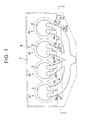
- FIG. 1 a cylinder head 1 of the internal combustion engine is fixed to a top face of a cylinder block 8.
- the cylinder block 8 is provided with a water jacket 11 to flow cooling water for the engine.
- each of four cylinders #1 to #4 disposed in a line is provided with a plurality of exhaust ports 3a, 3b (in this example, two exhaust ports for one cylinder).
- the plurality of exhaust ports 3a, 3b is disposed in a direction where the cylinders #1 to #4 are aligned, that is, in parallel with a longitudinal direction of the cylinder block 8.
- the exhaust ports 3a, 3b are connected to a combustion chamber 2 of their corresponding cylinder.
- the exhaust port 3a and the exhaust port 3b of the first cylinder #1 are joined at a downstream in an exhaust-gas flowing direction so as to form a collective exhaust port 4.
- the exhaust port 3a and the exhaust port 3b of the second cylinder #2 are joined at a downstream in an exhaust-gas flowing direction so as to form a collective exhaust port 5.
- the exhaust port 3a and the exhaust port 3b of the third cylinder #3 are joined at a downstream in an exhaust-gas flowing direction so as to form a collective exhaust port 6.
- the exhaust port 3a and the exhaust port 3b of the fourth cylinder #4 are joined at a downstream in an exhaust-gas flowing direction so as to form a collective exhaust port 7.
- the collective exhaust ports 4 to 7 are joined at a further downstream.
- the collective exhaust ports 4 to 7 are aligned in the same direction as the direction (a right-left direction in the figure) where the first to fourth cylinders #1 to #4 are aligned.
- the cylinder head 1 has a plurality of oil holes 9, 10 to flow, from the cylinder head 1 to the cylinder block 8, oil that has lubricated a valve system and so on in the internal combustion engine, and the plurality of oil holes 9, 10 is formed in parallel with the longitudinal direction of the cylinder block 8.
- the oil holes 9, 10 are opened on a surface of the cylinder head 1 which makes contact with the cylinder block 8.
- the plurality of oil holes 9, 10 includes: first oil holes 9 adjacent to the collective exhaust ports 4, 6, 7; and a second oil hole 10 provided further outside an outermost first oil hole 9 in the longitudinal direction of the cylinder block 8, the second oil hole 10 being placed farther from the collective exhaust port 7 than the outermost first oil hole 9.
- the first oil hole 9 adjacent to the outermost collective exhaust port 7 in the longitudinal direction of the cylinder block 8 is placed further outside the collective exhaust port 7. Further, the second oil hole 10 is placed further outside the first oil hole 9 adjacent to the collective exhaust port 7, in the longitudinal direction of the cylinder block 8.
- the second oil hole 10 is formed to have a diameter larger than that of the first oil hole 9.
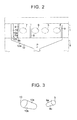
- FIG. 2 is a schematic drawing of the cylinder head 1 and the cylinder block 8 in FIG. 1 , when viewed from a direction of an arrow II-II.
- the cylinder block 8 includes an oil receiving portion 12 for receiving oil from the plurality of oil holes 9, 10, and the oil receiving portion 12 is formed so as to be adjacent to the water jacket 11 ( FIG. 1 ).
- the oil receiving portion 12 is formed in a shape extended long in the longitudinal direction of the cylinder block 8, and has an inner wall 12a of a shape for collecting, into a collecting portion P, the oil flowing from the plurality of the oil holes 9, 10.
- the collecting portion P of the oil receiving portion 12 is placed in a central part in an extending direction of the oil receiving portion 12 (in the longitudinal direction of the cylinder head 8), and is connected to an oil pan for retaining oil that lubricates each part of the cylinder internal combustion engine.
- FIG. 3 is a perspective view illustrating the second oil hole 10 illustrated in FIG. 2 and the first oil hole 9 closest to the second oil hole 10 (the first oil hole 9 adjacent to the collective exhaust port 7), when viewed from a cylinder-block-8 side. As can be seen from FIG.
- a portion of the inner peripheral surface of the first oil hole 9 closest to the second oil hole 10 which is closer to an opening 9b on an oil-receiving-portion-12 side is provided with an expanded portion 9a formed by expanding the first oil hole 9 toward the opening 9b.
- Oil that has lubricated the valve system and so on in the cylinder head 1 of the internal combustion engine illustrated in FIG. 2 flows into the oil receiving portion 12 of the cylinder block 8 through the first oil holes 9 and the second oil hole 10.
- the oil in the second oil hole 10 flows into the oil receiving portion 12
- the oil diffuses due to the portion of the inner peripheral surface of the second oil hole 10 which is closer to the opening 10b on the cylinder-block-8 side, that is, the oil diffuses due to the expanded portion 10a.
- the oil in the first oil hole 9 closest to the second oil hole 10 flows into the oil receiving portion 12
- the oil diffuses due to the portion of the inner peripheral surface of the first oil hole 9 which is closer to the opening 9b on the cylinder-block-8 side, that is, the oil diffuses due to the expanded portion 9a.
- the oil flowing into the oil receiving portion 12 from the first oil holes 9 and the second oil hole 10 flows into the collecting portion P along the inner wall 12a of the oil receiving portion 12.
- the oil thus collected in the collecting portion P of the oil receiving portion 12 is further returned to the oil pan of the internal combustion engine.
- the oil in the oil pan is sent to each part such as the valve system or the like of the internal combustion engine, and after the oil lubricates the each part, the oil is returned to the oil pan.
- the oil flowing through the second oil hole 10 is hard to receive heat from exhaust gas in the collective exhaust ports 4 to 7, as compared with the oil flowing through the first oil holes 9. This is because the second oil hole 10 is formed at a position farther from the collective exhaust ports 4 to 7 than the first oil holes 9. Further, the first oil hole 9 adjacent to the collective exhaust port 7 is placed between the second oil hole 10 and the collective exhaust port 7. The oil flowing through the first oil hole 9 interrupts heat transmission from the collective exhaust port 7 to the second oil hole 10. Hereby, the oil flowing through the second oil hole 10 is hard to receive heat from the exhaust gas in the collective exhaust port 7.
- the second oil hole 10 is formed to have a diameter larger than that of the first oil hole 9. This can increase a flow rate of the oil flowing through the second oil hole 10, among the oil flowing from the cylinder head 1 to the cylinder block 8 (the oil receiving portion 12) through the oil holes 9, 10. By increasing the flow rate of the oil in the second oil hole 10 that is hard to receive heat from the exhaust gas in the collective exhaust ports 4 to 7 as described above, it is possible to restrain an increase in temperature of the oil flowing from the cylinder head 1 to the cylinder block 8 (the oil receiving portion 12).
- the water jacket 11 for flowing cooling water for the internal-combustion engine is formed adjacent to the oil receiving portion 12 in the cylinder block 8. Accordingly, the oil flowing into the oil receiving portion 12 from the second oil hole 10 is effectively cooled down by heat exchange with the cooling water flowing through the water jacket 11 adjacent to the oil receiving portion 12.
- the oil receiving portion 12 is formed in a shape extended long in the longitudinal direction of the cylinder block 8. Then, the oil flowing into the oil receiving portion 12 from the second oil hole 10 flows into the collecting portion P along the inner wall 12a of the oil receiving portion 12 over a long distance. In this case, the heat exchange between the oil of the oil receiving portion 12 and the cooling water of the water jacket 11 can be performed through the oil receiving portion 12 formed in a shape extended long as mentioned earlier. This makes it possible to further effectively cool down the oil flowing into the oil receiving portion 12 from the second oil hole 10.
- the oil in the second oil hole 10 flows into the oil receiving portion 12, the oil diffuses due to the portion of the inner peripheral surface of the second oil hole 10 which is closer to the opening 10b on the cylinder-block-8 side, that is, the oil diffuses due to the expanded portion 10a.
- the oil flows over a large range of the inner wall 12a of the oil receiving portion 12 and then gathers at the collecting portion P. Accordingly, before the oil flows into the oil receiving portion 12 and gathers at the collecting portion P, the oil is effectively cooled down by heat exchange with the cooling water flowing through the water jacket 11.
- the oil in the first oil hole 9 closest to the second oil hole 10 flows into the oil receiving portion 12
- the oil diffuses due to the portion of the inner peripheral surface of the first oil hole 9 which is closer to the opening 9b on the cylinder-block-8 side, that is, the oil diffuses due to the expanded portion 9a.
- the oil flows over a large range of the inner wall 12a of the oil receiving portion 12 and then gathers at the collecting portion P. Accordingly, before the oil flows into the oil receiving portion 12 and gathers at the collecting portion P, the oil is effectively cooled down by heat exchange with the cooling water flowing through the water jacket 11.
- An expanded portion 9a may be formed in any of the first oil holes 9 other than the first oil hole 9 closest to the second oil hole 10.
- the expanded portion 9a of the first oil hole 9 and the expanded portion 10a of the second oil hole 10 may not necessarily be provided. It is conceivable that the collecting portion P is provided on an end (a right end in FIG. 2 ) of the oil receiving portion 12 which end is opposite to the part just under the second oil hole 10 instead of providing the collecting portion P in the central part in the extending direction of the oil receiving portion 12 (in the longitudinal direction of the cylinder block 8) as illustrated in FIG. 2 . In this case, a distance before the oil flowing into the oil receiving portion 12 from the second oil hole 10 reaches the collecting portion P is longest, which makes it possible to effectively cool down the oil before the oil reaches the collecting portion P.
- a plurality of passages respectively communicating with the oil holes 9, 10 may be formed in the cylinder block 8, so that the oil in each of the holes 9, 10 is returned into the oil pan separately via its corresponding passage.
- the exhaust port 3a and the exhaust port 3b of each of the cylinders #1 to #4 are joined per cylinder so as to form each of the collective exhaust ports 4 to 7, and the collective exhaust ports 4 to 7 are further joined at the downstream in the exhaust-gas flowing direction.
- all of the exhaust ports 3a, 3b of the cylinders #1 to #4 may be joined at a predetermined part in the exhaust-gas flowing direction.
- the collective exhaust ports 4 to 7 may be opened outward from the cylinder head, and an exhaust manifold may be connected to openings of the collective exhaust ports 4 to 7, so that respective exhaust gases from the collective exhaust ports 4 to 7 are collected by the exhaust manifold.
- the cylinder head 1 is easy to receive heat from the exhaust gas. In view of this, the application of the present invention yields a large effect.
Landscapes
- Engineering & Computer Science (AREA)
- Mechanical Engineering (AREA)
- General Engineering & Computer Science (AREA)
- Chemical & Material Sciences (AREA)
- Combustion & Propulsion (AREA)
- Lubrication Of Internal Combustion Engines (AREA)
- Cylinder Crankcases Of Internal Combustion Engines (AREA)
Abstract
When oil flows from a cylinder head (1) into a cylinder block (8) through oil holes (9, 10), the oil flowing through the second oil hole (10) is hard to receive heat from exhaust gas in collective exhaust ports (4 to 7), as compared with the oil flowing through the first oil holes (9). This is because the second oil hole (10) is formed outside an outermost collective exhaust port (7) in a longitudinal direction of the cylinder block (8), and the first oil hole (9) is formed between the collective exhaust port (7) and the second oil hole (10). Further, the second oil hole (10) is formed to have a diameter larger than that of the first oil hole (9). This increases a flow rate of the oil flowing through the second oil hole (10), among the oil flowing from the cylinder head (1) into the cylinder block (8) through the oil holes (9, 10).
Description
- The present invention relates to an oil circulation structure in an internal combustion engine.
- As an oil circulation structure in an internal combustion engine, there has been known such a structure in which a plurality of oil holes for flowing oil into a cylinder block from a cylinder head provided with a plurality of exhaust ports is formed in the cylinder head. Japanese Patent Application Publication No.
2013-155625 JP 2013-155625 A - In the oil circulation structure in the internal combustion engine, in a case where the oil holes are formed as described in
JP 2013-155625 A - The present invention provides an oil circulation structure in an internal combustion engine which circulation structure is able to restrain an increased in temperature of oil.
- A first aspect of the present invention relates to an oil circulation structure in an internal combustion engine. The oil circulation structure includes a cylinder block and a cylinder head. The cylinder head includes a plurality of exhaust ports. The cylinder head has a plurality of oil holes opened on a surface making contact with the cylinder block. Oil is supplied to the cylinder block through the plurality of oil holes. The plurality of oil holes includes a first oil hole and a second oil hole. The first oil hole is placed outside an outermost exhaust port in a longitudinal direction of the cylinder block. The second oil hole is placed outside the first oil hole in the longitudinal direction of the cylinder block. The second oil hole has a diameter larger than a diameter of the first oil hole. This increases a flow rate of the oil flowing through the second oil hole, among the oil flowing from the cylinder head to the cylinder block through the oil holes. The oil flowing through the second oil hole is hard to receive heat from exhaust gas in the exhaust port, as compared with the oil flowing through the first oil hole. This is because the second oil hole is formed at a position farther from the exhaust port than the first oil hole, and heat transmission from the exhaust port to the second oil hole is interrupted by the oil flowing through the first oil hole placed between the second oil hole and the exhaust port. By increasing the flow rate of the oil in the second oil hole that is hard to receive heat from the exhaust gas in the exhaust port as described above, it is possible to restrain an increase in temperature of the oil flowing from the cylinder head to the cylinder block.
- In the oil circulation structure, the cylinder block may include an oil receiving portion and a water jacket. The oil receiving portion may be configured to receive oil from the plurality of oil holes. The water jacket may be adjacent to the oil receiving portion. According to the oil circulation structure, the oil flowing into the oil receiving portion from the second oil hole is effectively cooled down by heat exchange with the cooling water flowing through the water jacket adjacent to the oil receiving portion.
- In the oil circulation structure, the second oil hole may have an opening on a cylinder-block side. An inner peripheral surface of the second oil hole may include a second portion on a cylinder-block side of the second oil hole. A diameter of the second portion may be expanded toward the opening of the second oil hole. According to the oil circulation structure, when the oil in the second oil hole flows into the oil receiving portion, the oil diffuses due to the second portion of the inner peripheral surface of the second oil hole which is closer to the opening on the cylinder-block side (the oil-receiving-portion side), that is, the oil diffuses due to the second portion expanded toward the opening. As a result, since the oil flows over a wide range of an inner wall of the oil receiving portion, the oil can be effectively cooled down by heat exchange with the cooling water of the water jacket.
- In the oil circulation structure, the first oil hole may have an opening on a cylinder-block side. An inner peripheral surface of the first oil hole may have on a cylinder-block side of the first oil hole. A diameter of the first portion may be expanded toward the opening of the first oil hole. According to the oil circulation structure, when the oil in the first oil hole flows into the oil receiving portion, the oil diffuses due to the first portion of the inner peripheral surface of the first oil hole which is closer to the opening on the cylinder-block side (the oil-receiving-portion side), that is, the oil diffuses due to the first portion expanded toward the opening. As a result, since the oil flows over a wide range of the inner wall of the oil receiving portion, the oil can be effectively cooled down by heat exchange with the cooling water of the water jacket. Accordingly, if the oil passing through the first oil hole receives heat from the exhaust gas in the exhaust port and its temperature is increased, the oil is effectively cooled down while the oil flows along the inner wall of the oil receiving portion, thereby restraining a temperature increase of the oil.
- Features, advantages, and technical and industrial significance of exemplary embodiments of the invention will be described below with reference to the accompanying drawings, in which like numerals denote like elements, and wherein:
-
FIG. 1 is a plan view diagrammatically illustrating a structure of exhaust ports in a cylinder head of an internal combustion engine, according to the present embodiment; -
FIG. 2 is a schematic drawing of the cylinder head and a cylinder block in the internal combustion engine ofFIG. 1 , when viewed from a direction of an arrow II-II; and -
FIG. 3 is a perspective view of an opening of a first oil hole and an opening of a second oil hole, according to the present embodiment, when viewed from an oil-receiving-portion side. - One embodiment of an oil circulation structure in an internal combustion engine is described below with reference to
FIGS. 1 to 3 . As illustrated inFIG. 1 , acylinder head 1 of the internal combustion engine is fixed to a top face of acylinder block 8. Thecylinder block 8 is provided with awater jacket 11 to flow cooling water for the engine. In thecylinder head 1, each of fourcylinders # 1 to #4 disposed in a line is provided with a plurality ofexhaust ports exhaust ports cylinders # 1 to #4 are aligned, that is, in parallel with a longitudinal direction of thecylinder block 8. Theexhaust ports combustion chamber 2 of their corresponding cylinder. - The
exhaust port 3a and theexhaust port 3b of thefirst cylinder # 1 are joined at a downstream in an exhaust-gas flowing direction so as to form acollective exhaust port 4. Theexhaust port 3a and theexhaust port 3b of thesecond cylinder # 2 are joined at a downstream in an exhaust-gas flowing direction so as to form acollective exhaust port 5. Theexhaust port 3a and theexhaust port 3b of thethird cylinder # 3 are joined at a downstream in an exhaust-gas flowing direction so as to form acollective exhaust port 6. Theexhaust port 3a and theexhaust port 3b of thefourth cylinder # 4 are joined at a downstream in an exhaust-gas flowing direction so as to form acollective exhaust port 7. Thecollective exhaust ports 4 to 7 are joined at a further downstream. Thecollective exhaust ports 4 to 7 are aligned in the same direction as the direction (a right-left direction in the figure) where the first tofourth cylinders # 1 to #4 are aligned. - The
cylinder head 1 has a plurality ofoil holes cylinder head 1 to thecylinder block 8, oil that has lubricated a valve system and so on in the internal combustion engine, and the plurality ofoil holes cylinder block 8. Theoil holes cylinder head 1 which makes contact with thecylinder block 8. The plurality ofoil holes first oil holes 9 adjacent to thecollective exhaust ports second oil hole 10 provided further outside an outermostfirst oil hole 9 in the longitudinal direction of thecylinder block 8, thesecond oil hole 10 being placed farther from thecollective exhaust port 7 than the outermostfirst oil hole 9. Thefirst oil hole 9 adjacent to the outermostcollective exhaust port 7 in the longitudinal direction of thecylinder block 8 is placed further outside thecollective exhaust port 7. Further, thesecond oil hole 10 is placed further outside thefirst oil hole 9 adjacent to thecollective exhaust port 7, in the longitudinal direction of thecylinder block 8. Thesecond oil hole 10 is formed to have a diameter larger than that of thefirst oil hole 9. -
FIG. 2 is a schematic drawing of thecylinder head 1 and thecylinder block 8 inFIG. 1 , when viewed from a direction of an arrow II-II. As illustrated inFIG. 2 , thecylinder block 8 includes anoil receiving portion 12 for receiving oil from the plurality ofoil holes oil receiving portion 12 is formed so as to be adjacent to the water jacket 11 (FIG. 1 ). Further, theoil receiving portion 12 is formed in a shape extended long in the longitudinal direction of thecylinder block 8, and has aninner wall 12a of a shape for collecting, into a collecting portion P, the oil flowing from the plurality of theoil holes oil receiving portion 12 is placed in a central part in an extending direction of the oil receiving portion 12 (in the longitudinal direction of the cylinder head 8), and is connected to an oil pan for retaining oil that lubricates each part of the cylinder internal combustion engine. - As illustrated in
FIG. 3 , a portion of the inner peripheral surface of thesecond oil hole 10 which is closer to anopening 10b on a cylinder-block-8 side (an oil-receiving-portion-12 side) is provided with an expandedportion 10a formed by expanding thesecond oil hole 10 toward theopening 10b.FIG. 3 is a perspective view illustrating thesecond oil hole 10 illustrated inFIG. 2 and thefirst oil hole 9 closest to the second oil hole 10 (thefirst oil hole 9 adjacent to the collective exhaust port 7), when viewed from a cylinder-block-8 side. As can be seen fromFIG. 3 , a portion of the inner peripheral surface of thefirst oil hole 9 closest to thesecond oil hole 10 which is closer to anopening 9b on an oil-receiving-portion-12 side is provided with an expandedportion 9a formed by expanding thefirst oil hole 9 toward theopening 9b. - Next will be described an operation of the oil circulation structure in the internal combustion engine. Oil that has lubricated the valve system and so on in the
cylinder head 1 of the internal combustion engine illustrated inFIG. 2 flows into theoil receiving portion 12 of thecylinder block 8 through thefirst oil holes 9 and thesecond oil hole 10. When the oil in thesecond oil hole 10 flows into theoil receiving portion 12, the oil diffuses due to the portion of the inner peripheral surface of thesecond oil hole 10 which is closer to theopening 10b on the cylinder-block-8 side, that is, the oil diffuses due to the expandedportion 10a. Further, when the oil in thefirst oil hole 9 closest to thesecond oil hole 10 flows into theoil receiving portion 12, the oil diffuses due to the portion of the inner peripheral surface of thefirst oil hole 9 which is closer to theopening 9b on the cylinder-block-8 side, that is, the oil diffuses due to the expandedportion 9a. Then, the oil flowing into theoil receiving portion 12 from thefirst oil holes 9 and thesecond oil hole 10 flows into the collecting portion P along theinner wall 12a of theoil receiving portion 12. Further, the oil thus collected in the collecting portion P of theoil receiving portion 12 is further returned to the oil pan of the internal combustion engine. The oil in the oil pan is sent to each part such as the valve system or the like of the internal combustion engine, and after the oil lubricates the each part, the oil is returned to the oil pan. - At the time when the oil is flowed into the cylinder block 8 (the oil receiving portion 12) from the
cylinder head 1, the oil flowing through thesecond oil hole 10 is hard to receive heat from exhaust gas in thecollective exhaust ports 4 to 7, as compared with the oil flowing through the first oil holes 9. This is because thesecond oil hole 10 is formed at a position farther from thecollective exhaust ports 4 to 7 than the first oil holes 9. Further, thefirst oil hole 9 adjacent to thecollective exhaust port 7 is placed between thesecond oil hole 10 and thecollective exhaust port 7. The oil flowing through thefirst oil hole 9 interrupts heat transmission from thecollective exhaust port 7 to thesecond oil hole 10. Hereby, the oil flowing through thesecond oil hole 10 is hard to receive heat from the exhaust gas in thecollective exhaust port 7. Further, thesecond oil hole 10 is formed to have a diameter larger than that of thefirst oil hole 9. This can increase a flow rate of the oil flowing through thesecond oil hole 10, among the oil flowing from thecylinder head 1 to the cylinder block 8 (the oil receiving portion 12) through the oil holes 9, 10. By increasing the flow rate of the oil in thesecond oil hole 10 that is hard to receive heat from the exhaust gas in thecollective exhaust ports 4 to 7 as described above, it is possible to restrain an increase in temperature of the oil flowing from thecylinder head 1 to the cylinder block 8 (the oil receiving portion 12). - According to the above embodiment described above, it is possible to obtain the following effects. It is possible to restrain an increase in temperature of the oil flowing from the
cylinder head 1 to thecylinder block 8. - The
water jacket 11 for flowing cooling water for the internal-combustion engine is formed adjacent to theoil receiving portion 12 in thecylinder block 8. Accordingly, the oil flowing into theoil receiving portion 12 from thesecond oil hole 10 is effectively cooled down by heat exchange with the cooling water flowing through thewater jacket 11 adjacent to theoil receiving portion 12. - The
oil receiving portion 12 is formed in a shape extended long in the longitudinal direction of thecylinder block 8. Then, the oil flowing into theoil receiving portion 12 from thesecond oil hole 10 flows into the collecting portion P along theinner wall 12a of theoil receiving portion 12 over a long distance. In this case, the heat exchange between the oil of theoil receiving portion 12 and the cooling water of thewater jacket 11 can be performed through theoil receiving portion 12 formed in a shape extended long as mentioned earlier. This makes it possible to further effectively cool down the oil flowing into theoil receiving portion 12 from thesecond oil hole 10. - At the time when the oil in the
second oil hole 10 flows into theoil receiving portion 12, the oil diffuses due to the portion of the inner peripheral surface of thesecond oil hole 10 which is closer to theopening 10b on the cylinder-block-8 side, that is, the oil diffuses due to the expandedportion 10a. Hereby, the oil flows over a large range of theinner wall 12a of theoil receiving portion 12 and then gathers at the collecting portion P. Accordingly, before the oil flows into theoil receiving portion 12 and gathers at the collecting portion P, the oil is effectively cooled down by heat exchange with the cooling water flowing through thewater jacket 11. - At the time when the oil in the
first oil hole 9 closest to thesecond oil hole 10 flows into theoil receiving portion 12, the oil diffuses due to the portion of the inner peripheral surface of thefirst oil hole 9 which is closer to theopening 9b on the cylinder-block-8 side, that is, the oil diffuses due to the expandedportion 9a. Hereby, the oil flows over a large range of theinner wall 12a of theoil receiving portion 12 and then gathers at the collecting portion P. Accordingly, before the oil flows into theoil receiving portion 12 and gathers at the collecting portion P, the oil is effectively cooled down by heat exchange with the cooling water flowing through thewater jacket 11. - Note that the above embodiment can be modified as follows, for example. An expanded
portion 9a may be formed in any of thefirst oil holes 9 other than thefirst oil hole 9 closest to thesecond oil hole 10. - The expanded
portion 9a of thefirst oil hole 9 and the expandedportion 10a of thesecond oil hole 10 may not necessarily be provided. It is conceivable that the collecting portion P is provided on an end (a right end inFIG. 2 ) of theoil receiving portion 12 which end is opposite to the part just under thesecond oil hole 10 instead of providing the collecting portion P in the central part in the extending direction of the oil receiving portion 12 (in the longitudinal direction of the cylinder block 8) as illustrated inFIG. 2 . In this case, a distance before the oil flowing into theoil receiving portion 12 from thesecond oil hole 10 reaches the collecting portion P is longest, which makes it possible to effectively cool down the oil before the oil reaches the collecting portion P. - Instead of forming the
oil receiving portion 12 in thecylinder block 8, a plurality of passages respectively communicating with the oil holes 9, 10 may be formed in thecylinder block 8, so that the oil in each of theholes - The
exhaust port 3a and theexhaust port 3b of each of thecylinders # 1 to #4 are joined per cylinder so as to form each of thecollective exhaust ports 4 to 7, and thecollective exhaust ports 4 to 7 are further joined at the downstream in the exhaust-gas flowing direction. However, instead of this, all of theexhaust ports cylinders # 1 to #4 may be joined at a predetermined part in the exhaust-gas flowing direction. - It is not necessary to join the
collective exhaust ports 4 to 7 together in thecylinder head 1. Thecollective exhaust ports 4 to 7 may be opened outward from the cylinder head, and an exhaust manifold may be connected to openings of thecollective exhaust ports 4 to 7, so that respective exhaust gases from thecollective exhaust ports 4 to 7 are collected by the exhaust manifold. - Note that, in a case where the
collective exhaust ports 4 to 7 are joined together in thecylinder head 1 as described in the above embodiment, thecylinder head 1 is easy to receive heat from the exhaust gas. In view of this, the application of the present invention yields a large effect.
Claims (4)
- An oil circulation structure in an internal combustion engine, the oil circulation structure comprising:a cylinder block (8); anda cylinder head (1) including a plurality of exhaust ports (3a, 3b), the cylinder head (1) having a plurality of oil holes (9, 10) opened on a surface making contact with the cylinder block (8) and configured so that oil can be supplied to the cylinder block (8) therethrough, the plurality of oil holes including a first oil hole (9) and a second oil hole (10), the first oil hole (9) being placed further outside an outermost exhaust port in a longitudinal direction of the cylinder block (8), the second oil hole (10) being placed further outside the first oil hole (9) in the longitudinal direction of the cylinder block (8), and the second oil hole (10) having a diameter larger than a diameter of the first oil hole (9).
- The oil circulation structure according to claim 1, wherein:the cylinder block includes an oil receiving portion (12) and a water jacket (11),the oil receiving portion (12) is configured to receive oil from the plurality of oil holes (9, 10), andthe water jacket (11) is adjacent to the oil receiving portion (12).
- The oil circulation structure according to claim 2, wherein:the second oil hole (10) has an opening (10b) on a cylinder-block side, andan inner peripheral surface of the second oil hole (10) includes a second portion (10a) on the cylinder-block side of the second oil hole (10), a diameter of the second portion (10a) becoming larger toward the opening (10b) of the second oil hole (10).
- The oil circulation structure according to claim 3, wherein:the first oil hole (9) has an opening (9b) on the cylinder-block side, andan inner peripheral surface of the first oil hole (9) includes a first portion (9a) on the cylinder-block side of the first oil hole (9), a diameter of the first portion (9a) becoming larger toward the opening (9b) of the first oil hole (9).
Applications Claiming Priority (1)
| Application Number | Priority Date | Filing Date | Title |
|---|---|---|---|
| JP2014091188A JP2015209802A (en) | 2014-04-25 | 2014-04-25 | Oil distribution structure in internal combustion engines |
Publications (1)
| Publication Number | Publication Date |
|---|---|
| EP2940262A1 true EP2940262A1 (en) | 2015-11-04 |
Family
ID=52997285
Family Applications (1)
| Application Number | Title | Priority Date | Filing Date |
|---|---|---|---|
| EP15164064.6A Withdrawn EP2940262A1 (en) | 2014-04-25 | 2015-04-17 | Oil circulation structure in internal combustion engine |
Country Status (5)
| Country | Link |
|---|---|
| US (1) | US20150308308A1 (en) |
| EP (1) | EP2940262A1 (en) |
| JP (1) | JP2015209802A (en) |
| CN (1) | CN105041498A (en) |
| BR (1) | BR102015007905A2 (en) |
Cited By (1)
| Publication number | Priority date | Publication date | Assignee | Title |
|---|---|---|---|---|
| EP3492729A1 (en) * | 2017-12-01 | 2019-06-05 | RENAULT s.a.s. | Cylinder head of a motor vehicle comprising an integrated exhaust manifold |
Citations (5)
| Publication number | Priority date | Publication date | Assignee | Title |
|---|---|---|---|---|
| JP2010223204A (en) * | 2009-02-25 | 2010-10-07 | Mitsubishi Motors Corp | Oil return passage structure of cylinder head with integrated exhaust port of multi-cylinder engine |
| JP2013155625A (en) | 2012-01-27 | 2013-08-15 | Toyota Motor Corp | Internal combustion engine |
| WO2014033528A1 (en) * | 2012-08-28 | 2014-03-06 | Toyota Jidosha Kabushiki Kaisha | Internal combustion engine |
| JP2014043826A (en) * | 2012-08-28 | 2014-03-13 | Toyota Motor Corp | Internal combustion engine |
| JP2014043825A (en) * | 2012-08-28 | 2014-03-13 | Toyota Motor Corp | Internal combustion engine |
Family Cites Families (3)
| Publication number | Priority date | Publication date | Assignee | Title |
|---|---|---|---|---|
| US5852992A (en) * | 1997-11-24 | 1998-12-29 | Ford Global Technologies, Inc. | Internal combuston engine having separated cylinder head oil drains and crankcase ventilation passages |
| JP3743355B2 (en) * | 2001-11-27 | 2006-02-08 | 日産自動車株式会社 | Internal combustion engine cylinder block |
| JP2003301742A (en) * | 2002-04-11 | 2003-10-24 | Toyota Industries Corp | Cylinder block for multicylinder engine |
-
2014
- 2014-04-25 JP JP2014091188A patent/JP2015209802A/en active Pending
-
2015
- 2015-03-27 US US14/671,230 patent/US20150308308A1/en not_active Abandoned
- 2015-04-09 BR BR102015007905A patent/BR102015007905A2/en not_active IP Right Cessation
- 2015-04-17 EP EP15164064.6A patent/EP2940262A1/en not_active Withdrawn
- 2015-04-23 CN CN201510196747.3A patent/CN105041498A/en active Pending
Patent Citations (5)
| Publication number | Priority date | Publication date | Assignee | Title |
|---|---|---|---|---|
| JP2010223204A (en) * | 2009-02-25 | 2010-10-07 | Mitsubishi Motors Corp | Oil return passage structure of cylinder head with integrated exhaust port of multi-cylinder engine |
| JP2013155625A (en) | 2012-01-27 | 2013-08-15 | Toyota Motor Corp | Internal combustion engine |
| WO2014033528A1 (en) * | 2012-08-28 | 2014-03-06 | Toyota Jidosha Kabushiki Kaisha | Internal combustion engine |
| JP2014043826A (en) * | 2012-08-28 | 2014-03-13 | Toyota Motor Corp | Internal combustion engine |
| JP2014043825A (en) * | 2012-08-28 | 2014-03-13 | Toyota Motor Corp | Internal combustion engine |
Cited By (2)
| Publication number | Priority date | Publication date | Assignee | Title |
|---|---|---|---|---|
| EP3492729A1 (en) * | 2017-12-01 | 2019-06-05 | RENAULT s.a.s. | Cylinder head of a motor vehicle comprising an integrated exhaust manifold |
| FR3074537A1 (en) * | 2017-12-01 | 2019-06-07 | Renault S.A.S. | HEAD OF A MOTOR VEHICLE COMPRISING AN INTEGRATED EXHAUST MANIFOLD |
Also Published As
| Publication number | Publication date |
|---|---|
| US20150308308A1 (en) | 2015-10-29 |
| CN105041498A (en) | 2015-11-11 |
| BR102015007905A2 (en) | 2016-04-19 |
| JP2015209802A (en) | 2015-11-24 |
Similar Documents
| Publication | Publication Date | Title |
|---|---|---|
| EP2951412B1 (en) | Internal combustion engine | |
| US20160186641A1 (en) | Cooling structure of internal combustion engine | |
| EP2497931A1 (en) | Cylinder head for an internal combustion engine, with integrated exhaust manifold and subgroups of exhaust conduits merging into manifold portions which are superimposed and spaced apart from each other | |
| CN204402682U (en) | A kind of cylinder cover structure | |
| JP2005188352A (en) | Exhaust manifold integrated engine cooling structure | |
| CN107288773B (en) | Water jacket structure of cylinder head | |
| US20160281583A1 (en) | Cylinder block of internal combustion engine | |
| TWI672436B (en) | Cylinder head | |
| EP3034846A1 (en) | Cylinder block | |
| US8960134B1 (en) | Targeted cooling with individualized feeding ports to cylinders | |
| EP2940262A1 (en) | Oil circulation structure in internal combustion engine | |
| JP6062312B2 (en) | Cylinder block cooling structure | |
| JP2009180109A (en) | Cooling structure of exhaust manifold integrated cylinder head | |
| CN114562378A (en) | Engine cylinder head, engine and automobile | |
| US10302040B2 (en) | Cylinder head for internal combustion engine | |
| JP6696125B2 (en) | Cylinder head cooling structure | |
| CN204175443U (en) | Cylinder head | |
| JP7119735B2 (en) | internal combustion engine | |
| JP2015129619A (en) | Engine egr cooler | |
| JP2015218662A (en) | Engine egr device | |
| CN204060958U (en) | Cylinder head | |
| JP2016142179A (en) | Cylinder cooling device | |
| JP2008095645A (en) | Head gasket of water-cooled inline multi-cylinder engine | |
| JP2022015676A (en) | Internal combustion engine | |
| JP2018131999A (en) | Cylinder head for engine |
Legal Events
| Date | Code | Title | Description |
|---|---|---|---|
| PUAI | Public reference made under article 153(3) epc to a published international application that has entered the european phase |
Free format text: ORIGINAL CODE: 0009012 |
|
| 17P | Request for examination filed |
Effective date: 20150417 |
|
| AK | Designated contracting states |
Kind code of ref document: A1 Designated state(s): AL AT BE BG CH CY CZ DE DK EE ES FI FR GB GR HR HU IE IS IT LI LT LU LV MC MK MT NL NO PL PT RO RS SE SI SK SM TR |
|
| AX | Request for extension of the european patent |
Extension state: BA ME |
|
| STAA | Information on the status of an ep patent application or granted ep patent |
Free format text: STATUS: THE APPLICATION HAS BEEN WITHDRAWN |
|
| 18W | Application withdrawn |
Effective date: 20160621 |