EP2940099A1 - Process for preparing red-emitting phosphors - Google Patents
Process for preparing red-emitting phosphors Download PDFInfo
- Publication number
- EP2940099A1 EP2940099A1 EP15165675.8A EP15165675A EP2940099A1 EP 2940099 A1 EP2940099 A1 EP 2940099A1 EP 15165675 A EP15165675 A EP 15165675A EP 2940099 A1 EP2940099 A1 EP 2940099A1
- Authority
- EP
- European Patent Office
- Prior art keywords
- phosphor
- process according
- combinations
- formula
- source
- Prior art date
- Legal status (The legal status is an assumption and is not a legal conclusion. Google has not performed a legal analysis and makes no representation as to the accuracy of the status listed.)
- Granted
Links
Images


Classifications
-
- C—CHEMISTRY; METALLURGY
- C09—DYES; PAINTS; POLISHES; NATURAL RESINS; ADHESIVES; COMPOSITIONS NOT OTHERWISE PROVIDED FOR; APPLICATIONS OF MATERIALS NOT OTHERWISE PROVIDED FOR
- C09K—MATERIALS FOR MISCELLANEOUS APPLICATIONS, NOT PROVIDED FOR ELSEWHERE
- C09K11/00—Luminescent materials, e.g. electroluminescent or chemiluminescent
- C09K11/08—Luminescent materials, e.g. electroluminescent or chemiluminescent containing inorganic luminescent materials
- C09K11/61—Luminescent materials, e.g. electroluminescent or chemiluminescent containing inorganic luminescent materials containing fluorine, chlorine, bromine, iodine or unspecified halogen elements
- C09K11/617—Silicates
-
- H—ELECTRICITY
- H10—SEMICONDUCTOR DEVICES; ELECTRIC SOLID-STATE DEVICES NOT OTHERWISE PROVIDED FOR
- H10H—INORGANIC LIGHT-EMITTING SEMICONDUCTOR DEVICES HAVING POTENTIAL BARRIERS
- H10H20/00—Individual inorganic light-emitting semiconductor devices having potential barriers, e.g. light-emitting diodes [LED]
- H10H20/80—Constructional details
- H10H20/85—Packages
- H10H20/851—Wavelength conversion means
- H10H20/8511—Wavelength conversion means characterised by their material, e.g. binder
- H10H20/8512—Wavelength conversion materials
-
- H—ELECTRICITY
- H10—SEMICONDUCTOR DEVICES; ELECTRIC SOLID-STATE DEVICES NOT OTHERWISE PROVIDED FOR
- H10H—INORGANIC LIGHT-EMITTING SEMICONDUCTOR DEVICES HAVING POTENTIAL BARRIERS
- H10H20/00—Individual inorganic light-emitting semiconductor devices having potential barriers, e.g. light-emitting diodes [LED]
- H10H20/80—Constructional details
- H10H20/85—Packages
- H10H20/851—Wavelength conversion means
- H10H20/8515—Wavelength conversion means not being in contact with the bodies
-
- H—ELECTRICITY
- H10—SEMICONDUCTOR DEVICES; ELECTRIC SOLID-STATE DEVICES NOT OTHERWISE PROVIDED FOR
- H10W—GENERIC PACKAGES, INTERCONNECTIONS, CONNECTORS OR OTHER CONSTRUCTIONAL DETAILS OF DEVICES COVERED BY CLASS H10
- H10W74/00—Encapsulations, e.g. protective coatings
-
- Y—GENERAL TAGGING OF NEW TECHNOLOGICAL DEVELOPMENTS; GENERAL TAGGING OF CROSS-SECTIONAL TECHNOLOGIES SPANNING OVER SEVERAL SECTIONS OF THE IPC; TECHNICAL SUBJECTS COVERED BY FORMER USPC CROSS-REFERENCE ART COLLECTIONS [XRACs] AND DIGESTS
- Y02—TECHNOLOGIES OR APPLICATIONS FOR MITIGATION OR ADAPTATION AGAINST CLIMATE CHANGE
- Y02B—CLIMATE CHANGE MITIGATION TECHNOLOGIES RELATED TO BUILDINGS, e.g. HOUSING, HOUSE APPLIANCES OR RELATED END-USER APPLICATIONS
- Y02B20/00—Energy efficient lighting technologies, e.g. halogen lamps or gas discharge lamps
Definitions
- Red-emitting phosphors based on complex fluoride materials activated by Mn 4+ can be utilized in combination with yellow/green emitting phosphors such as YAG:Ce or other garnet compositions to achieve warm white light (CCTs ⁇ 5000 K on the blackbody locus, color rendering index (CRI) >80) from a blue LED, equivalent to that produced by current fluorescent, incandescent and halogen lamps.
- YAG:Ce or other garnet compositions to achieve warm white light (CCTs ⁇ 5000 K on the blackbody locus, color rendering index (CRI) >80) from a blue LED, equivalent to that produced by current fluorescent, incandescent and halogen lamps.
- CCTs ⁇ 5000 K on the blackbody locus, color rendering index (CRI) >80 color rendering index
- These materials absorb blue light strongly and efficiently emit between about 610-635 nm with little deep red/NIR emission. Therefore, luminous efficacy is maximized compared to red phosphors that have significant emission in the deeper
- WO 2007/100824 describes preparation of complex fluoride phosphors using aqueous HF as solvent. The processes utilize significant quantities of this highly toxic material, and alternatives that eliminate HF or at least reduce the amount are economically advantageous.
- the present invention relates to an HF-free process for preparing a Mn 4+ doped phosphor of formula I A x [MF y ]:Mn +4 I wherein
- the process includes combining in an acidic solution, an A+ cation, an anion of formula MFy, and a Mn n+ source comprising a fluoromanganese compound; precipitating a Mn n+ containing phosphor precursor from the acidic solution; and contacting the Mn n+ containing phosphor precursor with a fluorine-containing oxidizing agent in gaseous form, at an elevated temperature, to form the Mn 4+ doped phosphor.
- a solution of a Mn n+ source in aqueous fluorosilicic acid is added to a solution of KF in water to precipitate the Mn n+ containing phosphor precursor, K 2 SiF 6 :Mn 2+ or K 2 SiF 6 :Mn 3+ .
- an acidic solution is the medium in which the A+ cation, the anion of formula MFy, and the Mn n+ source are combined to form the Mn n+ containing precursor.
- Suitable acidic solutions are ones in which both the anion of formula MF y , and the Mn n+ fluoroanion of the precursor are stable.
- the acid may be of formula H x [MF y ]; examples of suitable acids include H 2 SiF 6 , H 2 GeF 6 , H 2 TiF 6 , and combinations thereof.
- the acid is fluorosilicic acid.
- the A+ cations may be supplied as a salt, the corresponding anion for A + may be fluoride, chloride, acetate, chloride, oxalate, dihydrogen phosphate, or a combination thereof, particularly fluoride.
- suitable materials include KF, KHF, LiF, LiHF 2 , NaF, NaHF 2 , RbF, RbHF 2 , CsF, CsHF 2 , and combinations thereof.
- the anion is fluoride.
- the anion of formula MF y may be obtained from the acid of formula H x [MF y ], or a compound such as Cs 2 SiF 6 or MgSiF 6 ⁇ 6H 2 O may be used.
- Fluoromanganese compounds suitable for use as the Mn n+ source yield the Mn n+ fluoroanion when dissolved in the acidic solution.
- suitable Mn 2+ sources include K 2 MnF 4, KMnF 3 , MnF 2 , manganese (II) acetate, manganese(II) oxide, manganese(II) carbonate, manganese(II) nitrate, and combinations thereof.
- suitable Mn 3+ sources include K 2 MnF 5 ⁇ H 2 O, KMnF 4 , and MnF 3 , manganese (III) acetate, manganese(III) oxide, and combinations thereof. Hydrated forms of the Mn n+ sources may produce low concentrations of HF.
- Mn 4+ sources such as MnF 4, K 2 MnF 6 , and MnO 2 , may also be used, but may have limited stability or solubility in non-HF-containing solutions, leading to manganese reduction.
- the A + cation is dissolved in a basic solution, for example, an aqueous solution of a carbonate or hydroxide of A+.
- a basic solution for example, an aqueous solution of a carbonate or hydroxide of A+.
- the order of addition is not necessarily the same in all embodiments, and in some cases, the KF solution may be added to the acid solution. Amounts of the raw materials for the MF y , anion, the Mn n+ fluoroanion and AF are determined by the stoichiometry of the reaction to form the precursor.
- the precursor may be a Mn n+ containing complex fluoride phosphor of formula III Am [MF z ]:Mn n+ III wherein A, M, and n are as defined above, m is the absolute value of the charge of the [MF z ] ion; and 4 ⁇ z ⁇ 7.
- Mn n+ containing phosphor precursor that may be formed as an intermediate in a process according to the present invention is Mn 3+ containing K 2 SiF 6 .
- the Mn 4+ doped phosphor of formula I is sparingly soluble in the aqueous acidic solution and precipitates upon formation. If the phosphor is not sufficiently insoluble in the medium to precipitate, a poor solvent may be added to the solution, causing the phosphor to precipitate. Suitable solvents for use as the poor solvent are those that are not attacked by Mn n+ and include alcohols, ketones, carboxylic acids, and phosphoric acid, particularly acetone.
- the Mn n+ containing phosphor precursor may be converted to the Mn 4+ doped phosphor by contact with a fluorine-containing oxidizing agent in gaseous form at an elevated temperature.
- the temperature may range from about 200°C to about 700°C, particularly from about 350°C to about 600°C during contact, and in some embodiments from about 200°C to about 700°C. In various embodiments of the present invention, the temperature is at least 100°C, particularly at least 225°C, and more particularly at least 350°C.
- the phosphor precursor is contacted with the oxidizing agent for a period of time sufficient to convert it to a Mn 4+ doped phosphor.
- the fluorine-containing oxidizing agent may be F 2 , HF, SF 6 , BrF 5 , NH 4 HF 2 , NH 4 F, KF, AlF 3 , SbF 5 , ClF 3 , BrF 3 , KrF, XeF 2 , XeF 4 , NF 3 , SiF 4 , PbF 2 , ZnF 2 , SnF 2 , CdF 2 or a combination thereof.
- the fluorine-containing oxidizing agent is F 2 .
- the amount of oxidizing agent in the atmosphere may be varied, particularly in conjunction with variation of time and temperature.
- the atmosphere may include at least 0.5% F 2 , although a lower concentration may be effective in some embodiments.
- the atmosphere may include at least 5% F 2 and more particularly at least 20% F 2 .
- the atmosphere may additionally include nitrogen, helium, neon, argon, krypton, xenon, and combinations with the fluorine-containing oxidizing agent.
- the atmosphere contains about 20% F 2 and about 80% nitrogen.
- the manner of contacting the Mn n+ containing phosphor precursor with the fluorine-containing oxidizing agent is not critical and may be accomplished in any way sufficient to convert the phosphor precursor to a phosphor having the desired properties.
- the chamber containing the precursor may be dosed and then sealed such that an overpressure develops as the chamber is heated, and in others, the fluorine and nitrogen mixture is flowed throughout the anneal process ensuring a more uniform pressure.
- an additional dose of the fluorine-containing oxidizing agent may be introduced after a period of time.
- a flux material may be mixed with the Mn n+ containing precursor before annealing.
- Use of a flux may be desirable where the Mn n+ containing phosphor precursor is deficient in A + relative to the product Mn 4+ doped phosphor, that is, where the ratio [A + ]/([Mn n+ ] + [M]) is less than or equal to 2, but is not limited thereto.
- Color stability and quantum efficiency of phosphors prepared by a process according to the present invention may be enhanced by treating the phosphor in particulate form with a saturated solution of a composition of formula II A x [MF y ] II
- K 2 SiF 6 :Mn 4+ maybe treated with a solution of K 2 SiF 6 in HF at room temperature to improve color stability and quantum efficiency of the phosphor.
- the temperature at which the phosphor is contacted with the solution ranges from about 20°C to about 50°C.
- the period of time required to produce the phosphor ranges from about one minute to about five hours, particularly from about five minutes to about one hour.
- Concentration of hydrofluoric acid in the aqueous HF solutions ranges from about 20% w/w to about 70% w/w, particularly about 40% w/w to about 70% w/w. Less concentrated solutions may result in lower yields of the phosphor.
- the Mn n+ containing phosphor precursors utilized in processes according to the present invention and Mn 4+ doped phosphors produced thereby are complex fluoride materials.
- the term complex fluoride material means a coordination compound, containing at least one coordination center, surrounded by fluoride ions acting as ligands, and charge-compensated by counter ions as necessary.
- the coordination center is Si and the counterion is K.
- Complex fluorides are occasionally written down as a combination of simple, binary fluorides but such a representation does not indicate the coordination number for the ligands around the coordination center.
- the square brackets indicate that the complex ion they encompass is a new chemical species, different from the simple fluoride ion.
- the activator ion (Mn 4+ ) also acts as a coordination center, substituting part of the centers of the host lattice, for example, Si.
- the host lattice (including the counter ions) may further modify the excitation and emission properties of the activator ion.
- Mn 4+ doped phosphors that may be prepared by a process according to the present invention are selected from the group consisting of
- Mn 4+ doped phosphors examples include K 2 [SiF 6 ]:Mn 4+ , K 2 [TiF 6 ]:Mn 4+ , Cs 2 [TiF 6 ] :Mn 4+ , Rb 2 [TiF 6 ] :Mn 4+ , Cs 2 [SiF 6 ] :Mn 4+ , Rb 2 [SiF 6 ] :Mn 4+ , Na 2 [TiF 6 ]:Mn 4+ , Na 2 [ZrF 6 ]:Mn 4+ , K 3 [ZrF 7 ]:Mn 4+ , K 3 [BiF 6 ]:Mn 4+ , K 3 [YF 6 ]:Mn 4+ , K 3 [LaF 6 ]:Mn 4+ , K 3 [GdF 6 ]:Mn 4+ , K 3 [NbF 7 ]:Mn 4+
- the coordination center M is Si, Ge, Sn, Ti, Zr, or a combination thereof. More particularly, the coordination center is Si, Ge, Ti, or a combination thereof, the counterion A in formula I is Na, K, Rb, Cs, or a combination thereof, and y is 6.
- Mn 4+ doped phosphors prepared by a process according to the present invention may display good color stability after exposure to light flux.
- a lighting apparatus incorporating a Mn 4+ doped phosphor prepared by a process according to the present invention may have a color shift of ⁇ 1.5 MacAdam ellipses after operating for at least 2,000 hour at a LED current density greater than 2 A/cm 2 , a LED wall-plug efficiency greater than 40%, and a board temperature greater than 25°C, preferably wherein the MacAdam ellipse color shift is ⁇ 1.
- the lighting apparatus may have a color shift of ⁇ 2 MacAdam ellipses after operating for 30 minutes at a LED current density greater than 70 A/cm 2 , a LED wall-plug efficiency greater than 18%, and a board temperature greater than 25°C.
- Stability of the phosphor outside an LED package as measured by % intensity loss of the phosphor after exposure to light flux of at least 80 w/cm 2 at a temperature of at least 50°C; % intensity loss of the color stable phosphors may be ⁇ 4% after 21 hours.
- Lighting apparatus 10 includes a semiconductor radiation source, shown as light emitting diode (LED) chip 12, and leads 14 electrically attached to the LED chip.
- the leads 14 may be thin wires supported by a thicker lead frame(s) 16 or the leads may be self-supported electrodes and the lead frame may be omitted.
- the leads 14 provide current to LED chip 12 and thus cause it to emit radiation.
- the lamp may include any semiconductor blue or UV light source that is capable of producing white light when its emitted radiation is directed onto the phosphor.
- the semiconductor light source is a blue emitting LED doped with various impurities.
- the LED may comprise a semiconductor diode based on any suitable III-V, II-VI or IV-IV semiconductor layers and having an emission wavelength of about 250 to 550 nm.
- the LED may contain at least one semiconductor layer comprising GaN, ZnSe or SiC.
- the chip is a near-uv or blue emitting LED having a peak emission wavelength from about 400 to about 500 nm.
- LED semiconductors are known in the art.
- the radiation source is described herein as an LED for convenience. However, as used herein, the term is meant to encompass all semiconductor radiation sources including, e.g., semiconductor laser diodes.
- LED chip may be replaced by another radiation source unless otherwise noted and that any reference to semiconductor, semiconductor LED, or LED chip is merely representative of any appropriate radiation source, including, but not limited to, organic light emitting diodes.
- phosphor composition 22 is radiationally coupled to the LED chip 12. Radiationally coupled means that the elements are associated with each other so radiation from one is transmitted to the other. Phosphor composition 22 is deposited on the LED 12 by any appropriate method. For example, a water based suspension of the phosphor(s) can be formed, and applied as a phosphor layer to the LED surface. In one such method, a silicone slurry in which the phosphor particles are randomly suspended is placed around the LED. This method is merely exemplary of possible positions of phosphor composition 22 and LED 12. Thus, phosphor composition 22 may be coated over or directly on the light emitting surface of the LED chip 12 by coating and drying the phosphor suspension over the LED chip 12.
- the suspension is cured at an appropriate temperature.
- Both the shell 18 and the encapsulant 20 should be transparent to allow white light 24 to be transmitted through those elements.
- the median particle size of the phosphor composition ranges from about 1 to about 50 microns, particularly from about 15 to about 35 microns.
- Radiation (indicated by arrow 126) emitted by the LED chip 112 mixes with the light emitted by the phosphor 122, and the mixed light appears as white light 124. If the phosphor is to be interspersed within the encapsulant material 120, then a phosphor powder may be added to a polymer precursor, and loaded around the LED chip 112. The polymer or silicone precursor may then be cured to solidify the polymer or silicone. Other known phosphor interspersion methods may also be used, such as transfer molding.
- FIG. 3 illustrates a third possible structure of the system according to the present invention.
- the structure of the embodiment shown in FIG. 3 is similar to that of FIG. 1 , except that the phosphor composition 222 is coated onto a surface of the envelope 218, instead of being formed over the LED chip 212.
- the phosphor composition 222 is preferably coated on the inside surface of the envelope 218, although the phosphor may be coated on the outside surface of the envelope, if desired.
- the phosphor composition 222 may be coated on the entire surface of the envelope, or only a top portion of the surface of the envelope.
- the radiation 226 emitted by the LED chip 212 mixes with the light emitted by the phosphor composition 222, and the mixed light appears as white light 224.
- the structures of FIGS. 1-3 may be combined, and the phosphor may be located in any two or all three locations, or in any other suitable location, such as separately from the envelope, or integrated into the LED.
- the LED chip 412 may be mounted in a reflective cup 430.
- the cup 430 may be made from or coated with a dielectric material, such as alumina, titania, or other dielectric powders known in the art, or be coated by a reflective metal, such as aluminum or silver.
- the remainder of the structure of the embodiment of FIG. 4 is the same as those of any of the previous figures, and can include two leads 416, a conducting wire 432, and an encapsulant material 420.
- the reflective cup 430 is supported by the first lead 416 and the conducting wire 432 is used to electrically connect the LED chip 412 with the second lead 416.
- SMD surface mounted device
- This SMD is a "side-emitting type” and has a light-emitting window 552 on a protruding portion of a light guiding member 554.
- An SMD package may comprise an LED chip as defined above, and a phosphor material that is excited by the light emitted from the LED chip.
- Other backlight devices include, but are not limited to, TVs, computers, smartphones, tablet computers and other handheld devices that have a display including a semiconductor light source and a Mn 4+ doped phosphor prepared by a process according to the present invention.
- Lamp 10 When used with an LED emitting at from 350 to 550 nm and one or more other appropriate phosphors, the resulting lighting system will produce a light having a white color.
- Lamp 10 may also include scattering particles (not shown), which are embedded in the encapsulant material.
- the scattering particles may comprise, for example, alumina or titania. The scattering particles effectively scatter the directional light emitted from the LED chip, preferably with a negligible amount of absorption.
- phosphor composition 22 may include one or more other phosphors.
- the resultant light emitted by the assembly will be a white light.
- Other phosphors such as green, blue, yellow, red, orange, or other color phosphors may be used in the blend to customize the white color of the resulting light and produce specific spectral power distributions.
- phosphor composition 22 materials suitable for use in phosphor composition 22 include electroluminescent polymers such as polyfluorenes, preferably poly(9,9-dioctyl fluorene) and copolymers thereof, such as poly(9,9'-dioctylfluorene-co-bis-N,N'-(4-butylphenyl)diphenylamine) (F8-TFB); poly(vinylcarbazole) and polyphenylenevinylene and their derivatives.
- the light emitting layer may include a blue, yellow, orange, green or red phosphorescent dye or metal complex, or a combination thereof.
- phosphorescent dye Materials suitable for use as the phosphorescent dye include, but are not limited to, tris(1-phenylisoquinoline) iridium (III) (red dye), tris(2-phenylpyridine) iridium (green dye) and Iridium (III) bis(2-(4,6-difluorephenyl)pyridinato-N,C2) (blue dye).
- fluorescent and phosphorescent metal complexes from ADS (American Dyes Source, Inc.) may also be used.
- ADS green dyes include ADS060GE, ADS061 GE, ADS063GE, and ADS066GE, ADS078GE, and ADS090GE.
- Suitable phosphors for use in phosphor composition 22 include, but are not limited to:
- the ratio of each of the individual phosphors in the phosphor blend may vary depending on the characteristics of the desired light output.
- the relative proportions of the individual phosphors in the various embodiment phosphor blends may be adjusted such that when their emissions are blended and employed in an LED lighting device, there is produced visible light of predetermined x and y values on the CIE chromaticity diagram.
- a white light is preferably produced. This white light may, for instance, may possess an x value in the range of about 0.20 to about 0.55, and a y value in the range of about 0.20 to about 0.55.
- the exact identity and amounts of each phosphor in the phosphor composition can be varied according to the needs of the end user.
- the material can be used for LEDs intended for liquid crystal display (LCD) backlighting. In this application, the LED color point would be appropriately tuned based upon the desired white, red, green, and blue colors after passing through an LCD/color filter combination.
- Mn 4+ doped phosphors prepared by a process according to the present invention may be used in applications other than those described above.
- the material may be used as a phosphor in a fluorescent lamp, in a cathode ray tube, in a plasma display device or in a liquid crystal display (LCD).
- the material may also be used as a scintillator in an electromagnetic calorimeter, in a gamma ray camera, in a computed tomography scanner or in a laser. These uses are merely exemplary and not limiting.
- a laser diode emitting at 446 nm was coupled to an optical fiber with a collimator at its other end.
- the power output was 310 mW and the beam diameter at the sample was 700 microns. This is equivalent to a flux of 80 W/cm 2 at the sample surface.
- the spectral power distribution (SPD) spectrum that is a combination of the scattered radiation from the laser and the emission from the excited phosphor is collected with a 1 meter (diameter) integrating sphere and the data processed with the spectrometer software (Specwin).
- the integrated power from the laser and the phosphor emission were recorded over a period of about 21 hours by integrating the SPD from 400nm to 500nm and 550 nm to 700 nm respectively.
- the first 90 minutes of the measurement are discarded to avoid effects due to the thermal stabilization of the laser.
- a Mn-doped potassium fluorosilicate phosphor, K 2 SiF 6 :Mn 4+ , obtained from a commercial source, containing 0.84 wt% Mn, based on total weight was annealed at 540°C in 10 psia under a 20%F 2 /80%N 2 atmosphere for 8 hours.
- the annealed phosphor powder was treated with a saturated solution of K 2 SiF 6 by placing the powder ( ⁇ 10 g) in a Teflon beaker containing 100 mL of a saturated solution of K 2 SiF 6 (initially made by adding ⁇ 17 g of K 2 SiF 6 in 40% HF at room temperature, stirring, and filtering the solution). The suspension was stirred slowly, and the residue is filtered and dried under vacuum. The dried filtrate was washed with acetone 3-5 times and heated at 100°C for 10 minutes to remove HF.
- K 2 CO 3 (5.56 g) and KHF 2 (3.78 g) in 20 ml water was gradually added to a rapidly stirring solution of K 2 MnF 5 ⁇ H 2 O (0.266 g) in 35% H 2 SiF 6 (10 ml).
- the resulting K 2 SiF 6 slurry was vacuum filtered, rinsed with glacial acetic acid to remove trace KF and KHF 2 , rinsed three times with acetone, and then dried in a vacuum desiccator.
- a furnace chamber containing the Mn 3+ containing K 2 SiF 6 of Example 2 was evacuated and then filled with an atmosphere containing 20% fluorine gas and 80% nitrogen gas and heated to 500°C. The furnace was held at that temperature for about 8 hours, then the furnace was cooled.
- the emission spectrum of the product was essentially identical to that of the K 2 SiF 6 :Mn 4+ material of Comparative Example 1.
Landscapes
- Chemical & Material Sciences (AREA)
- Inorganic Chemistry (AREA)
- Engineering & Computer Science (AREA)
- Materials Engineering (AREA)
- Organic Chemistry (AREA)
- Luminescent Compositions (AREA)
Abstract
Description
- Red-emitting phosphors based on complex fluoride materials activated by Mn4+, such as those described in
US 7,358,542 ,US 7,497,973 , andUS 7,648,649 , can be utilized in combination with yellow/green emitting phosphors such as YAG:Ce or other garnet compositions to achieve warm white light (CCTs<5000 K on the blackbody locus, color rendering index (CRI) >80) from a blue LED, equivalent to that produced by current fluorescent, incandescent and halogen lamps. These materials absorb blue light strongly and efficiently emit between about 610-635 nm with little deep red/NIR emission. Therefore, luminous efficacy is maximized compared to red phosphors that have significant emission in the deeper red where eye sensitivity is poor. Quantum efficiency can exceed 85% under blue (440-460 nm) excitation. - Methods for preparation of the phosphors typically require hydrofluoric acid as a solvent. For example,
WO 2007/100824 describes preparation of complex fluoride phosphors using aqueous HF as solvent. The processes utilize significant quantities of this highly toxic material, and alternatives that eliminate HF or at least reduce the amount are economically advantageous. - Briefly, in one aspect, the present invention relates to an HF-free process for preparing a Mn4+ doped phosphor of formula I
Ax[MFy]:Mn+4 I
wherein - A is Li, Na, K, Rb, Cs, or a combination thereof;
- M is Si, Ge, Sn, Ti, Zr, Al, Ga, In, Sc, Hf, Y, La, Nb, Ta, Bi, Gd, or a combination thereof;
- x is the absolute value of the charge of the [MFy] ion;
- y is 5, 6 or 7; and
- n is 2 or 3.
- The process includes combining in an acidic solution, an A+ cation, an anion of formula MFy, and a Mnn+ source comprising a fluoromanganese compound; precipitating a Mnn+ containing phosphor precursor from the acidic solution; and contacting the Mnn+ containing phosphor precursor with a fluorine-containing oxidizing agent in gaseous form, at an elevated temperature, to form the Mn4+ doped phosphor.
- In particular embodiments, a solution of a Mnn+ source in aqueous fluorosilicic acid is added to a solution of KF in water to precipitate the Mnn+ containing phosphor precursor, K2SiF6:Mn2+ or K2SiF6:Mn3+.
- Various features, aspects, and advantages of the present invention will become better understood when the following detailed description is read with reference to the accompanying drawings in which like characters represent like parts throughout the drawings, wherein:
-
FIG. 1 is a schematic cross-sectional view of a lighting apparatus in accordance with one embodiment of the invention; -
FIG. 2 is a schematic cross-sectional view of a lighting apparatus in accordance with another embodiment of the invention; -
FIG. 3 is a schematic cross-sectional view of a lighting apparatus in accordance with yet another embodiment of the invention; -
FIG. 4 is a cutaway side perspective view of a lighting apparatus in accordance with one embodiment of the invention; -
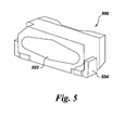
FIG. 5 is a schematic perspective view of a surface-mounted device (SMD) backlight LED. - In the processes of the present invention, an acidic solution is the medium in which the A+ cation, the anion of formula MFy, and the Mnn+ source are combined to form the Mnn+ containing precursor. Suitable acidic solutions are ones in which both the anion of formula MFy, and the Mnn+ fluoroanion of the precursor are stable. The acid may be of formula Hx[MFy]; examples of suitable acids include H2SiF6, H2GeF6, H2TiF6, and combinations thereof. In particular embodiments, the acid is fluorosilicic acid.
- The A+ cations may be supplied as a salt, the corresponding anion for A+ may be fluoride, chloride, acetate, chloride, oxalate, dihydrogen phosphate, or a combination thereof, particularly fluoride. Examples of suitable materials include KF, KHF, LiF, LiHF2, NaF, NaHF2, RbF, RbHF2, CsF, CsHF2, and combinations thereof. In particular embodiments, the anion is fluoride. The anion of formula MFy may be obtained from the acid of formula Hx[MFy], or a compound such as Cs2SiF6 or MgSiF6·6H2O may be used. Fluoromanganese compounds suitable for use as the Mnn+ source yield the Mnn+ fluoroanion when dissolved in the acidic solution. Examples of suitable Mn2+ sources include K2MnF4, KMnF3, MnF2, manganese (II) acetate, manganese(II) oxide, manganese(II) carbonate, manganese(II) nitrate, and combinations thereof. Examples of suitable Mn3+ sources include K2MnF5·H2O, KMnF4, and MnF3, manganese (III) acetate, manganese(III) oxide, and combinations thereof. Hydrated forms of the Mnn+ sources may produce low concentrations of HF. Mn4+ sources, such as MnF4, K2MnF6, and MnO2, may also be used, but may have limited stability or solubility in non-HF-containing solutions, leading to manganese reduction.
- The anion of formula MFy, and Mnn+ source are combined with an A+ cation and an anion of formula MFy in the acidic solution, and the Mnn+ containing phosphor precursor is precipitated. Fluoride or bifluoride anion, or a combination thereof may also be present in the solution; a convenient source of the A+ cation and the fluoride or bifluoride anion may be the fluoride or bifluoride salt of A+, AF or AHF2. In particular embodiments, the Mnn+ source is combined with the acid, which may also provide the anion of formula MFy, and the A+ cation is added thereto. In some cases, the A+ cation is dissolved in a basic solution, for example, an aqueous solution of a carbonate or hydroxide of A+. The order of addition is not necessarily the same in all embodiments, and in some cases, the KF solution may be added to the acid solution. Amounts of the raw materials for the MFy, anion, the Mnn+ fluoroanion and AF are determined by the stoichiometry of the reaction to form the precursor.
- The precursor may be a Mnn+ containing complex fluoride phosphor of formula III
Am [MFz]:Mnn+ III
wherein A, M, and n are as defined above,
m is the absolute value of the charge of the [MFz] ion; and
- One example of a Mnn+ containing phosphor precursor that may be formed as an intermediate in a process according to the present invention is Mn3+ containing K2SiF6.
- In particular embodiments, the phosphor of formula I is K2SiF6:Mn4+, and the Mnn+ source is combined with the SiF6 anion and KF to yield the Mnn+ containing K2SiF6. For example, the Mnn+ source may be dissolved in aqueous fluorosilicic acid and added to a solution of KF in water to precipitate the Mnn+ containing phosphor precursor, K2SiF6:Mn2+ or K2SiF6:Mn3+.
- In some embodiments, the Mn4+ doped phosphor of formula I is sparingly soluble in the aqueous acidic solution and precipitates upon formation. If the phosphor is not sufficiently insoluble in the medium to precipitate, a poor solvent may be added to the solution, causing the phosphor to precipitate. Suitable solvents for use as the poor solvent are those that are not attacked by Mnn+ and include alcohols, ketones, carboxylic acids, and phosphoric acid, particularly acetone.
- The Mnn+ containing phosphor precursor may be converted to the Mn4+ doped phosphor by contact with a fluorine-containing oxidizing agent in gaseous form at an elevated temperature. The temperature may range from about 200°C to about 700°C, particularly from about 350°C to about 600°C during contact, and in some embodiments from about 200°C to about 700°C. In various embodiments of the present invention, the temperature is at least 100°C, particularly at least 225°C, and more particularly at least 350°C. The phosphor precursor is contacted with the oxidizing agent for a period of time sufficient to convert it to a Mn4+ doped phosphor. Time and temperature are interrelated, and may be adjusted together, for example, increasing time while reducing temperature, or increasing temperature while reducing time. The contacting step may include multiple periods of contact, of varying time and temperature, and the precursor may be rehomogenized between the periods to improve uniformity of the treatment. In particular embodiments, the phosphor precursor is contacted with the oxidizing agent for a period of at least eight hours and a temperature of at least 250°C, for example, at about 425°C for about four hours and then at a temperature of about 560°C for about four hours.
- The fluorine-containing oxidizing agent may be F2, HF, SF6, BrF5, NH4HF2, NH4F, KF, AlF3, SbF5, ClF3, BrF3, KrF, XeF2, XeF4, NF3, SiF4, PbF2, ZnF2, SnF2, CdF2 or a combination thereof. In particular embodiments, the fluorine-containing oxidizing agent is F2. The amount of oxidizing agent in the atmosphere may be varied, particularly in conjunction with variation of time and temperature. Where the fluorine-containing oxidizing agent is F2, the atmosphere may include at least 0.5% F2, although a lower concentration may be effective in some embodiments. In particular the atmosphere may include at least 5% F2 and more particularly at least 20% F2. The atmosphere may additionally include nitrogen, helium, neon, argon, krypton, xenon, and combinations with the fluorine-containing oxidizing agent. In particular embodiments, the atmosphere contains about 20% F2 and about 80% nitrogen.
- The manner of contacting the Mnn+ containing phosphor precursor with the fluorine-containing oxidizing agent is not critical and may be accomplished in any way sufficient to convert the phosphor precursor to a phosphor having the desired properties. In some embodiments, the chamber containing the precursor may be dosed and then sealed such that an overpressure develops as the chamber is heated, and in others, the fluorine and nitrogen mixture is flowed throughout the anneal process ensuring a more uniform pressure. In some embodiments, an additional dose of the fluorine-containing oxidizing agent may be introduced after a period of time.
- A flux material may be mixed with the Mnn+ containing precursor before annealing. Use of a flux may be desirable where the Mnn+ containing phosphor precursor is deficient in A+ relative to the product Mn4+ doped phosphor, that is, where the ratio [A+]/([Mnn+] + [M]) is less than or equal to 2, but is not limited thereto. Suitable A+-containing flux materials for use as a flux include compounds of formula AX, EX2, MF2 or MF3, where M is Si, Ge, Sn, Ti, Zr, Al, Ga, In, Sc, Hf, Y, La, Nb, Ta, Bi, Gd, or a combination thereof, particularly monofluorides and bifluorides of potassium, sodium and rubidium, KF and KHF2, NaF and NaHF2, RbF and RbHF2, and combinations thereof. In particular embodiments, the A+-containing flux material is KF or KHF2, or a combination thereof. The flux material may be removed from the phosphor product by washing with a suitable solvent, such as acetic acid.
- Color stability and quantum efficiency of phosphors prepared by a process according to the present invention may be enhanced by treating the phosphor in particulate form with a saturated solution of a composition of formula II
Ax [MFy] II
- in aqueous hydrofluoric acid, as described in
US 8,252,613 . For example, K2SiF6:Mn4+ maybe treated with a solution of K2SiF6 in HF at room temperature to improve color stability and quantum efficiency of the phosphor. The temperature at which the phosphor is contacted with the solution ranges from about 20°C to about 50°C. The period of time required to produce the phosphor ranges from about one minute to about five hours, particularly from about five minutes to about one hour. Concentration of hydrofluoric acid in the aqueous HF solutions ranges from about 20% w/w to about 70% w/w, particularly about 40% w/w to about 70% w/w. Less concentrated solutions may result in lower yields of the phosphor. - The Mnn+ containing phosphor precursors utilized in processes according to the present invention and Mn4+ doped phosphors produced thereby are complex fluoride materials. In the context of the present invention, the term complex fluoride material means a coordination compound, containing at least one coordination center, surrounded by fluoride ions acting as ligands, and charge-compensated by counter ions as necessary. In one example, K2SiF6:Mn4+, the coordination center is Si and the counterion is K. Complex fluorides are occasionally written down as a combination of simple, binary fluorides but such a representation does not indicate the coordination number for the ligands around the coordination center. The square brackets (occasionally omitted for simplicity) indicate that the complex ion they encompass is a new chemical species, different from the simple fluoride ion. The activator ion (Mn4+) also acts as a coordination center, substituting part of the centers of the host lattice, for example, Si. The host lattice (including the counter ions) may further modify the excitation and emission properties of the activator ion.
- In some embodiments, Mn4+ doped phosphors that may be prepared by a process according to the present invention are selected from the group consisting of
- (A) A2[MF5]:Mn4+, where M is selected from Al, Ga, In, and combinations thereof;
- (B) A3[MF6]:Mn4+, where M is selected from Al, Ga, In, and combinations thereof;
- (C) Zn2[MF7]:Mn4+, where M is selected from Al, Ga, In, and combinations thereof;
- (D) A[In2F7]:Mn4+;
- (E) A2[MF6]:Mn4+, where M is selected from Ge, Si, Sn, Ti, Zr, and combinations thereof;
- (F) E[MF6]:Mn4+, where E is selected from Mg, Ca, Sr, Ba, Zn, and combinations thereof; and where M is selected from Ge, Si, Sn, Ti, Zr, and combinations thereof;
- (G) Ba0.65Zr0.35F2.70:Mn4+;
- (H) A3[ZrF7]:Mn4+;
- Examples of Mn4+ doped phosphors that may be prepared by a process according to the present invention include K2[SiF6]:Mn4+, K2[TiF6]:Mn4+, Cs2[TiF6] :Mn4+, Rb2[TiF6] :Mn4+, Cs2[SiF6] :Mn4+, Rb2[SiF6] :Mn4+, Na2[TiF6]:Mn4+, Na2[ZrF6]:Mn4+, K3[ZrF7]:Mn4+, K3[BiF6]:Mn4+, K3[YF6]:Mn4+, K3[LaF6]:Mn4+, K3[GdF6]:Mn4+, K3[NbF7]:Mn4+, K3[TaF7]:Mn4+. In particular embodiments of the, the coordination center M is Si, Ge, Sn, Ti, Zr, or a combination thereof. More particularly, the coordination center is Si, Ge, Ti, or a combination thereof, the counterion A in formula I is Na, K, Rb, Cs, or a combination thereof, and y is 6.
- Mn4+ doped phosphors prepared by a process according to the present invention may display good color stability after exposure to light flux. A lighting apparatus incorporating a Mn4+ doped phosphor prepared by a process according to the present invention may have a color shift of ≤1.5 MacAdam ellipses after operating for at least 2,000 hour at a LED current density greater than 2 A/cm2, a LED wall-plug efficiency greater than 40%, and a board temperature greater than 25°C, preferably wherein the MacAdam ellipse color shift is ≤1. Under accelerated test conditions, the lighting apparatus may have a color shift of ≤2 MacAdam ellipses after operating for 30 minutes at a LED current density greater than 70 A/cm2, a LED wall-plug efficiency greater than 18%, and a board temperature greater than 25°C. Stability of the phosphor outside an LED package as measured by % intensity loss of the phosphor after exposure to light flux of at least 80 w/cm2 at a temperature of at least 50°C; % intensity loss of the color stable phosphors may be ≤ 4% after 21 hours.
- A lighting apparatus or light emitting assembly or
lamp 10 according to one embodiment of the present invention is shown inFIG. 1 .Lighting apparatus 10 includes a semiconductor radiation source, shown as light emitting diode (LED)chip 12, and leads 14 electrically attached to the LED chip. The leads 14 may be thin wires supported by a thicker lead frame(s) 16 or the leads may be self-supported electrodes and the lead frame may be omitted. The leads 14 provide current toLED chip 12 and thus cause it to emit radiation. - The lamp may include any semiconductor blue or UV light source that is capable of producing white light when its emitted radiation is directed onto the phosphor. In one embodiment, the semiconductor light source is a blue emitting LED doped with various impurities. Thus, the LED may comprise a semiconductor diode based on any suitable III-V, II-VI or IV-IV semiconductor layers and having an emission wavelength of about 250 to 550 nm. In particular, the LED may contain at least one semiconductor layer comprising GaN, ZnSe or SiC. For example, the LED may comprise a nitride compound semiconductor represented by the formula IniGajAlkN (where 0≤i; 0≤j; 0≤k and I + j + k =1) having an emission wavelength greater than about 250 nm and less than about 550 nm. In particular embodiments, the chip is a near-uv or blue emitting LED having a peak emission wavelength from about 400 to about 500 nm. Such LED semiconductors are known in the art. The radiation source is described herein as an LED for convenience. However, as used herein, the term is meant to encompass all semiconductor radiation sources including, e.g., semiconductor laser diodes. Further, although the general discussion of the exemplary structures of the invention discussed herein is directed toward inorganic LED based light sources, it should be understood that the LED chip may be replaced by another radiation source unless otherwise noted and that any reference to semiconductor, semiconductor LED, or LED chip is merely representative of any appropriate radiation source, including, but not limited to, organic light emitting diodes.
- In
lighting apparatus 10,phosphor composition 22 is radiationally coupled to theLED chip 12. Radiationally coupled means that the elements are associated with each other so radiation from one is transmitted to the other.Phosphor composition 22 is deposited on theLED 12 by any appropriate method. For example, a water based suspension of the phosphor(s) can be formed, and applied as a phosphor layer to the LED surface. In one such method, a silicone slurry in which the phosphor particles are randomly suspended is placed around the LED. This method is merely exemplary of possible positions ofphosphor composition 22 andLED 12. Thus,phosphor composition 22 may be coated over or directly on the light emitting surface of theLED chip 12 by coating and drying the phosphor suspension over theLED chip 12. In the case of a silicone-based suspension, the suspension is cured at an appropriate temperature. Both theshell 18 and theencapsulant 20 should be transparent to allowwhite light 24 to be transmitted through those elements. Although not intended to be limiting, in some embodiments, the median particle size of the phosphor composition ranges from about 1 to about 50 microns, particularly from about 15 to about 35 microns. - In other embodiments,
phosphor composition 22 is interspersed within theencapsulant material 20, instead of being formed directly on theLED chip 12. The phosphor (in the form of a powder) may be interspersed within a single region of theencapsulant material 20 or throughout the entire volume of the encapsulant material. Blue light emitted by theLED chip 12 mixes with the light emitted byphosphor composition 22, and the mixed light appears as white light. If the phosphor is to be interspersed within the material ofencapsulant 20, then a phosphor powder may be added to a polymer or silicone precursor, loaded around theLED chip 12, and then the polymer precursor may be cured to solidify the polymer or silicone material. Other known phosphor interspersion methods may also be used, such as transfer loading. - In yet another embodiment,
phosphor composition 22 is coated onto a surface of theshell 18, instead of being formed over theLED chip 12. The phosphor composition is preferably coated on the inside surface of theshell 18, although the phosphor may be coated on the outside surface of the shell, if desired.Phosphor composition 22 may be coated on the entire surface of the shell or only a top portion of the surface of the shell. The UV/blue light emitted by theLED chip 12 mixes with the light emitted byphosphor composition 22, and the mixed light appears as white light. Of course, the phosphor may be located in any two or all three locations or in any other suitable location, such as separately from the shell or integrated into the LED. -
FIG. 2 illustrates a second structure of the system according to the present invention. Corresponding numbers fromFIGS. 1-4 (e.g. 12 inFIG. 1 and 112 inFIG. 2 ) relate to corresponding structures in each of the figures, unless otherwise stated. The structure of the embodiment ofFIG. 2 is similar to that ofFIG. 1 , except that thephosphor composition 122 is interspersed within theencapsulant material 120, instead of being formed directly on theLED chip 112. The phosphor (in the form of a powder) may be interspersed within a single region of the encapsulant material or throughout the entire volume of the encapsulant material. Radiation (indicated by arrow 126) emitted by theLED chip 112 mixes with the light emitted by thephosphor 122, and the mixed light appears aswhite light 124. If the phosphor is to be interspersed within theencapsulant material 120, then a phosphor powder may be added to a polymer precursor, and loaded around theLED chip 112. The polymer or silicone precursor may then be cured to solidify the polymer or silicone. Other known phosphor interspersion methods may also be used, such as transfer molding. -
FIG. 3 illustrates a third possible structure of the system according to the present invention. The structure of the embodiment shown inFIG. 3 is similar to that ofFIG. 1 , except that thephosphor composition 222 is coated onto a surface of theenvelope 218, instead of being formed over theLED chip 212. Thephosphor composition 222 is preferably coated on the inside surface of theenvelope 218, although the phosphor may be coated on the outside surface of the envelope, if desired. Thephosphor composition 222 may be coated on the entire surface of the envelope, or only a top portion of the surface of the envelope. Theradiation 226 emitted by theLED chip 212 mixes with the light emitted by thephosphor composition 222, and the mixed light appears aswhite light 224. Of course, the structures ofFIGS. 1-3 may be combined, and the phosphor may be located in any two or all three locations, or in any other suitable location, such as separately from the envelope, or integrated into the LED. - In any of the above structures, the lamp may also include a plurality of scattering particles (not shown), which are embedded in the encapsulant material. The scattering particles may comprise, for example, alumina or titania. The scattering particles effectively scatter the directional light emitted from the LED chip, preferably with a negligible amount of absorption.
- As shown in a fourth structure in
FIG. 4 , theLED chip 412 may be mounted in areflective cup 430. Thecup 430 may be made from or coated with a dielectric material, such as alumina, titania, or other dielectric powders known in the art, or be coated by a reflective metal, such as aluminum or silver. The remainder of the structure of the embodiment ofFIG. 4 is the same as those of any of the previous figures, and can include twoleads 416, aconducting wire 432, and anencapsulant material 420. Thereflective cup 430 is supported by thefirst lead 416 and theconducting wire 432 is used to electrically connect theLED chip 412 with thesecond lead 416. - Another structure (particularly for backlight applications) is a surface mounted device ("SMD") type
light emitting diode 550, e.g. as illustrated inFIG. 5 . This SMD is a "side-emitting type" and has a light-emittingwindow 552 on a protruding portion of alight guiding member 554. An SMD package may comprise an LED chip as defined above, and a phosphor material that is excited by the light emitted from the LED chip. Other backlight devices include, but are not limited to, TVs, computers, smartphones, tablet computers and other handheld devices that have a display including a semiconductor light source and a Mn4+ doped phosphor prepared by a process according to the present invention. - When used with an LED emitting at from 350 to 550 nm and one or more other appropriate phosphors, the resulting lighting system will produce a light having a white color.
Lamp 10 may also include scattering particles (not shown), which are embedded in the encapsulant material. The scattering particles may comprise, for example, alumina or titania. The scattering particles effectively scatter the directional light emitted from the LED chip, preferably with a negligible amount of absorption. - In addition to the Mn4+ doped phosphor,
phosphor composition 22 may include one or more other phosphors. When used in a lighting apparatus in combination with a blue or near UV LED emitting radiation in the range of about 250 to 550 nm, the resultant light emitted by the assembly will be a white light. Other phosphors such as green, blue, yellow, red, orange, or other color phosphors may be used in the blend to customize the white color of the resulting light and produce specific spectral power distributions. Other materials suitable for use inphosphor composition 22 include electroluminescent polymers such as polyfluorenes, preferably poly(9,9-dioctyl fluorene) and copolymers thereof, such as poly(9,9'-dioctylfluorene-co-bis-N,N'-(4-butylphenyl)diphenylamine) (F8-TFB); poly(vinylcarbazole) and polyphenylenevinylene and their derivatives. In addition, the light emitting layer may include a blue, yellow, orange, green or red phosphorescent dye or metal complex, or a combination thereof. Materials suitable for use as the phosphorescent dye include, but are not limited to, tris(1-phenylisoquinoline) iridium (III) (red dye), tris(2-phenylpyridine) iridium (green dye) and Iridium (III) bis(2-(4,6-difluorephenyl)pyridinato-N,C2) (blue dye). Commercially available fluorescent and phosphorescent metal complexes from ADS (American Dyes Source, Inc.) may also be used. ADS green dyes include ADS060GE, ADS061 GE, ADS063GE, and ADS066GE, ADS078GE, and ADS090GE. ADS blue dyes include ADS064BE, ADS065BE, and ADS070BE. ADS red dyes include ADS067RE, ADS068RE, ADS069RE, ADS075RE, ADS076RE, ADS067RE, and ADS077RE. - Suitable phosphors for use in
phosphor composition 22 include, but are not limited to: - ((Sr1-z (Ca, Ba, Mg, Zn)z)1-(x+w)(Li, Na, K, Rb)wCex)3(Al1-ySiy)O4+y3+(x-w)F1-y-3(x-w), 0<x≤0.10, 0≤y≤0.5, 0≤z≤0.5, 0≤w≤x;
- (Ca, Ce)3Sc2Si3O12(CaSiG);
- (Sr,Ca,Ba)3Al1-xSixO4+xF1-x:Ce3+ (SASOF));
- (Ba,Sr,Ca)5(PO4)3(Cl,F,Br,OH):Eu2+,Mn2+; (Ba,Sr,Ca)BPO5:Eu2+,Mn2+;
- (Sr,Ca)10(PO4)6*νB2O3:Eu2+ (wherein 0<ν≤1); Sr2Si3O8*2SrCl2:Eu2+;
- (Ca,Sr,Ba)3MgSi2O8:Eu2+,Mn2+; BaAl8O13:Eu2+;
- 2SrO*0.84P2O5*0.16B2O3:Eu2+;
- (Ba,Sr,Ca)MgAl10O17:Eu2+,Mn2+;(Ba,Sr,Ca)Al2O4:Eu2+;
- (Y,Gd,Lu,Sc,La)BO3:Ce3+,Tb3+;
- ZnS:Cu+,Cl-; ZnS:Cu+,Al3+; ZnS:Ag+,Cl-; ZnS:Ag+,Al3+; (Ba,Sr,Ca)2Si1-O4-2·:Eu2+ (wherein 0≤ξ≤0.2); (Ba,Sr,Ca)2(Mg,Zn)Si2O7:Eu2+;
- (Sr,Ca,Ba)(Al,Ga,In)2S4:Eu2+;
- (Y,Gd,Tb,La,Sm,Pr,Lu)3(Al,Ga)5αO12-3/2α:Ce3+ (wherein 0≤α≤0.5);
- (Ca,Sr)8(Mg,Zn)(SiO4)4Cl2:Eu2+,Mn2+; Na2Gd2B2O7:Ce3+,Tb3+;
- (Sr,Ca,Ba,Mg,Zn)2P2O7:Eu2+,Mn2+;(Gd,Y,Lu,La)2O3:Eu3+,Bi3+;
- (Gd,Y,Lu,La)2O2S:Eu3+,Bi3+; (Gd,Y,Lu,La)VO4:Eu3+,Bi3+; (Ca,Sr)S:Eu2+,Ce3+;
- SrY2S4:Eu2+; CaLa2S4:Ce3+; (Ba,Sr,Ca)MgP2O7:Eu2+,Mn2+;
- (Y,Lu)2WO6:Eu3+,Mo6+;
- (Ba,Sr,Ca)βSiγNµ:Eu2+ (wherein 2β+4γ=3µ); Ca3(SiO4)Cl2:Eu2+;
- (Lu,Sc,Y,Tb)2-u-vCevCa1+uLiwMg2-wPw(Si,Ge)3-wO12-u/2 (where -0.5≤u≤1, 0<v≤0.1, and 0≤w≤0.2); (Y,Lu,Gd)2-ϕCaϕSi4N6+ϕC1-ϕ:Ce3+, (wherein 0≤ϕ≤0.5);
- (Lu,Ca,Li,Mg,Y), α-SiAlON doped with Eu2+ and/or Ce3+;
- (Ca,Sr,Ba)SiO2N2:Eu2+,Ce3+; β-SiAlON:Eu2+,3.5MgO*0.5MgF2*GeO2:Mn4+; Ca1-c-fCecEufAl1+cSi1-cN3, (where 0≤c≤0.2, 0≤f≤0.2); Ca1-h-rCehEurAl1-h(Mg,Zn)hSiN3,
- (where 0≤h≤0.2, 0≤r≤0.2); Ca1-2s-tCes(Li,Na)sEutAlSiN3, (where 0≤s≤0.2, 0≤f≤0.2, s+t>0); and Ca1-σ-χ--φCeσ(Li,Na)χEuφAl1+σ-χSi1-σ+χN3, (where 0≤σ≤0.2, 0≤χ≤0.4, 0≤φ≤0.2).
- The ratio of each of the individual phosphors in the phosphor blend may vary depending on the characteristics of the desired light output. The relative proportions of the individual phosphors in the various embodiment phosphor blends may be adjusted such that when their emissions are blended and employed in an LED lighting device, there is produced visible light of predetermined x and y values on the CIE chromaticity diagram. As stated, a white light is preferably produced. This white light may, for instance, may possess an x value in the range of about 0.20 to about 0.55, and a y value in the range of about 0.20 to about 0.55. As stated, however, the exact identity and amounts of each phosphor in the phosphor composition can be varied according to the needs of the end user. For example, the material can be used for LEDs intended for liquid crystal display (LCD) backlighting. In this application, the LED color point would be appropriately tuned based upon the desired white, red, green, and blue colors after passing through an LCD/color filter combination.
- Mn4+ doped phosphors prepared by a process according to the present invention may be used in applications other than those described above. For example, the material may be used as a phosphor in a fluorescent lamp, in a cathode ray tube, in a plasma display device or in a liquid crystal display (LCD). The material may also be used as a scintillator in an electromagnetic calorimeter, in a gamma ray camera, in a computed tomography scanner or in a laser. These uses are merely exemplary and not limiting.
- A laser diode emitting at 446 nm was coupled to an optical fiber with a collimator at its other end. The power output was 310 mW and the beam diameter at the sample was 700 microns. This is equivalent to a flux of 80 W/cm2 at the sample surface. The spectral power distribution (SPD) spectrum that is a combination of the scattered radiation from the laser and the emission from the excited phosphor is collected with a 1 meter (diameter) integrating sphere and the data processed with the spectrometer software (Specwin). At intervals of two minutes, the integrated power from the laser and the phosphor emission were recorded over a period of about 21 hours by integrating the SPD from 400nm to 500nm and 550 nm to 700 nm respectively. The first 90 minutes of the measurement are discarded to avoid effects due to the thermal stabilization of the laser. The percentage of intensity loss due to laser damage is calculated as follows:

- While only the emitter power from the phosphor is plotted, the integrated power from the laser emission as well as its peak position was monitored to ensure that the laser remained stable (variations of less than 1%) during the experiment.
- A Mn-doped potassium fluorosilicate phosphor, K2SiF6:Mn4+, obtained from a commercial source, containing 0.84 wt% Mn, based on total weight was annealed at 540°C in 10 psia under a 20%F2/80%N2 atmosphere for 8 hours. The annealed phosphor powder was treated with a saturated solution of K2SiF6 by placing the powder (∼10 g) in a Teflon beaker containing 100 mL of a saturated solution of K2SiF6 (initially made by adding ∼17 g of K2SiF6 in 40% HF at room temperature, stirring, and filtering the solution). The suspension was stirred slowly, and the residue is filtered and dried under vacuum. The dried filtrate was washed with acetone 3-5 times and heated at 100°C for 10 minutes to remove HF.
- A solution of hydrochloric acid (45 ml of 37% HCl) was gradually added to a slurry of potassium bifluoride (15.62g KHF2) and potassium permanganate (15.8 g KMnO4) in 10.5 ml 48-49% HF. After the addition was complete, the temperature was increased to 70°C to complete the reaction and drive off dissolved Cl2. The contents of the flask were vacuum filtered. The filtrate was rinsed with glacial acetic acid to remove KHF2, and with acetone three times, then dried in a vacuum desiccator. Yield: 23 grams of pink-rose colored K2MnF5·H2O.
- A solution of K2CO3 (5.56 g) and KHF2 (3.78 g) in 20 ml water was gradually added to a rapidly stirring solution of K2MnF5·H2O (0.266 g) in 35% H2SiF6 (10 ml). The resulting K2SiF6 slurry was vacuum filtered, rinsed with glacial acetic acid to remove trace KF and KHF2, rinsed three times with acetone, and then dried in a vacuum desiccator.
- A furnace chamber containing the Mn3+ containing K2SiF6 of Example 2 was evacuated and then filled with an atmosphere containing 20% fluorine gas and 80% nitrogen gas and heated to 500°C. The furnace was held at that temperature for about 8 hours, then the furnace was cooled. The emission spectrum of the product was essentially identical to that of the K2SiF6:Mn4+ material of Comparative Example 1.
- While only certain features of the invention have been illustrated and described herein, many modifications and changes will occur to those skilled in the art. It is, therefore, to be understood that the appended claims are intended to cover all such modifications and changes as fall within the true spirit of the invention.
- Various aspects and embodiments of the present invention are defined by the following numbered clauses:
- 1. A process for preparing a Mn4+ doped phosphor of formula I,
Ax [MFy]:Mn+4 I
the process comprising combining an A+ cation, an anion of formula MFy, and a Mnn+ source comprising a fluoromanganese compound in an acidic solution;
precipitating a Mnn+ containing phosphor precursor from the acidic solution; and
contacting the Mnn+ containing phosphor precursor with a fluorine-containing oxidizing agent in gaseous form, at an elevated temperature, to form the Mn4+ doped phosphor;
wherein- A is Li, Na, K, Rb, Cs, or a combination thereof;
- M is Si, Ge, Sn, Ti, Zr, Al, Ga, In, Sc, Hf, Y, La, Nb, Ta, Bi, Gd, or a combination thereof;
- x is the absolute value of the charge of the [MFy] ion;
- y is 5, 6 or 7; and
- n is 2 or 3.
- 2. A process according to clause 1, additionally comprising combining a fluoride or bifluoride anion, or a combination thereof, with the A+ cation, the anion of formula MFy, and the Mnn+ source.
- 3. A process according to any preceding clause, wherein the Mn4+ doped phosphor is K2SiF6:Mn4+.
- 4. A process according to any preceding clause, wherein the anion of formula [MFy] is SiF6.
- 5. A process according to any preceding clause, wherein the A+ cation is derived from KF, KHF2, or a combination thereof.
- 6. A process according to any preceding clause, wherein the Mnn+ source is selected from K2MnF5·H2O, KMnF4, K2MnF4, KMnF3, MnF2, MnF3, and combinations thereof.
- 7. A process according to any preceding clause, wherein the Mnn+ source is K2MnF5·H2O.
- 8. A process according to any preceding clause, wherein the acidic solution is aqueous fluorosilicic acid.
- 9. A process according to any preceding clause, wherein the fluorine-containing oxidizing agent is F2.
- 10. A process according to any preceding clause, wherein the step of contacting the Mnn+ containing phosphor precursor with the fluorine-containing oxidizing agent additionally comprises contacting the Mnn+ containing phosphor precursor with the fluorine-containing oxidizing agent and compound of formula AX, where X is F, Cl, Br, I, HF2,or a combination thereof.
- 11. A process according to any preceding clause, comprising
- combining a solution comprising fluorosilicic acid and the Mnn+ source with a potassium fluoride compound selected from KF, KHF2, and combinations thereof;
- precipitating a Mnn+ containing phosphor precursor; and
- exposing the Mnn+ containing phosphor precursor to an atmosphere comprising at least 20% fluorine gas at an elevated temperature, to form the Mn4+ doped phosphor;
- wherein the Mnn+ source comprises a potassium fluoromanganese compound selected from K2MnF5·H2O, KMnF4, MnF3, and combinations thereof.
- 12. A process according to any preceding clause, treating the phosphor in particulate form with a saturated solution of a composition of formula II in aqueous hydrofluoric acid
Ax [MFy] II.
- 13. A Mn4+ doped phosphor prepared by a process according to any preceding clause.
- 14. A lighting apparatus comprising a semiconductor light source and the Mn4+ doped phosphor prepared by a process according to any preceding clause.
- 15. A backlight device comprising a semiconductor light source and the Mn4+ doped phosphor prepared by a process according to any preceding clause.
- 16. A process for preparing a Mn4+ doped phosphor, the process comprising
- combining an A+ cation, an anion of formula MFy, and a Mnn+ source comprising a fluoromanganese compound in an acidic solution;
- precipitating a Mnn+ containing phosphor precursor from the acidic solution; and
- contacting the Mnn+ containing phosphor precursor with a fluorine-containing oxidizing agent in gaseous form, at an elevated temperature, to form the Mn4+ doped phosphor; wherein the Mn4+ doped phosphor is selected from the group consisting of
- (A) A2[MF5]:Mn4+, where M is selected from Al, Ga, In, and combinations thereof;
- (B) A3[MF6]:Mn4+, where M is selected from Al, Ga, In, and combinations thereof;
- (C) Zn2[MF7]:Mn4+, where M is selected from Al, Ga, In, and combinations thereof;
- (D) A[In2F7]:Mn4+;
- (E) A2[MF6]:Mn4+, where M is selected from Ge, Si, Sn, Ti, Zr, and combinations thereof;
- (F) E[MF6]:Mn4+, where E is selected from Mg, Ca, Sr, Ba, Zn, and combinations thereof; and where M is selected from Ge, Si, Sn, Ti, Zr, and combinations thereof;
- (G) Ba0.65Zr0.35F2.70:Mn4+; and
- (H) A3[ZrF7]:Mn4+; and
- A is Li, Na, K, Rb, Cs, or a combination thereof.
- 17. A process according to any preceding clause, wherein the acidic solution is aqueous fluorosilicic acid.
- 18. A process according to any preceding clause, wherein the fluorine-containing oxidizing agent is F2.
- 19. A Mn4+ doped phosphor prepared by a process according to any preceding clause.
- 20. A lighting apparatus comprising a semiconductor light source; and Mn4+ doped phosphor prepared by a process according to any preceding clause.
- 21. A backlight device comprising a semiconductor light source; and a Mn4+ doped phosphor prepared by a process according to any preceding clause.
- 22. A Mnn+ containing complex fluoride compound of formula III
Am [MFz]:Mnn+ III
wherein- A is Li, Na, K, Rb, Cs, or a combination thereof;
- M is Si, Ge, Sn, Ti, Zr, Al, Ga, In, Sc, Hf, Y, La, Nb, Ta, Bi, Gd, or a combination thereof;
- m is the absolute value of the charge of the [MFz] ion;
- 4 ≤ z < 7; and
- n is 2 or 3;
- 23. A Mnn+ containing complex fluoride phosphor according to any preceding clause, of formula K2SiF6:Mn3+.
Claims (15)
- A process for preparing a Mn4+ doped phosphor of formula I,
Ax [MFy]:Mn+4 I
the process comprising combining an A+ cation, an anion of formula MFy, and a Mnn+ source comprising a fluoromanganese compound in an acidic solution;
precipitating a Mnn+ containing phosphor precursor from the acidic solution; and
contacting the Mnn+ containing phosphor precursor with a fluorine-containing oxidizing agent in gaseous form, at an elevated temperature, to form the Mn4+ doped phosphor;
whereinA is Li, Na, K, Rb, Cs, or a combination thereof;M is Si, Ge, Sn, Ti, Zr, Al, Ga, In, Sc, Hf, Y, La, Nb, Ta, Bi, Gd, or a combination thereof;x is the absolute value of the charge of the [MFy] ion;y is 5, 6 or 7; andn is 2 or 3. - A process according to claim 1, additionally comprising combining a fluoride or bifluoride anion, or a combination thereof, with the A+ cation, the anion of formula MFy, and the Mnn+ source.
- A process according to any preceding claim, wherein the Mn4+ doped phosphor is K2SiF6:Mn4+.
- A process according to any preceding claim, wherein the anion of formula [MFy] is SiF6.
- A process according to any preceding claim, wherein the A+ cation is derived from KF, KHF2, or a combination thereof.
- A process according to any preceding claim, wherein the Mnn+ source is selected from K2MnF5·H2O, KMnF4, K2MnF4, KMnF3, MnF2, MnF3, and combinations thereof.
- A process according to any preceding claim, wherein the Mnn+ source is K2MnF5·H2O.
- A process according to any preceding claim, wherein the acidic solution is aqueous fluorosilicic acid.
- A process according to any preceding claim, wherein the fluorine-containing oxidizing agent is F2.
- A process according to any preceding claim, wherein the step of contacting the Mnn+ containing phosphor precursor with the fluorine-containing oxidizing agent additionally comprises contacting the Mnn+ containing phosphor precursor with the fluorine-containing oxidizing agent and compound of formula AX, where X is F, Cl, Br, I, HF2,or a combination thereof.
- A process according to any preceding claim, comprising
combining a solution comprising fluorosilicic acid and the Mnn+ source with a potassium fluoride compound selected from KF, KHF2, and combinations thereof;
precipitating a Mnn+ containing phosphor precursor; and
exposing the Mnn+ containing phosphor precursor to an atmosphere comprising at least 20% fluorine gas at an elevated temperature, to form the Mn4+ doped phosphor;
wherein the Mnn+ source comprises a potassium fluoromanganese compound selected from K2MnF5·H2O, KMnF4, MnF3, and combinations thereof. - A process according to any preceding claim, treating the phosphor in particulate form with a saturated solution of a composition of formula II in aqueous hydrofluoric acid
Ax [MFy] II.
- A lighting apparatus (10) comprising a semiconductor light source (12) and the Mn4+ doped phosphor prepared by a process according to any preceding claim.
- A backlight device (10) comprising a semiconductor light source (112) and the Mn4+ doped phosphor prepared by a process according to any of claims 1 to 12.
- A process for preparing a Mn4+ doped phosphor, the process comprising
combining an A+ cation, an anion of formula MFy, and a Mnn+ source comprising a fluoromanganese compound in an acidic solution;
precipitating a Mnn+ containing phosphor precursor from the acidic solution; and
contacting the Mnn+ containing phosphor precursor with a fluorine-containing oxidizing agent in gaseous form, at an elevated temperature, to form the Mn4+ doped phosphor; wherein the Mn4+ doped phosphor is selected from the group consisting of(A) A2[MF5]:Mn4+, where M is selected from Al, Ga, In, and combinations thereof;(B) A3[MF6]:Mn4+, where M is selected from Al, Ga, In, and combinations thereof;(C) Zn2[MF7]:Mn4+, where M is selected from Al, Ga, In, and combinations thereof;(D) A[In2F7]:Mn4+;(E) A2[MF6]:Mn4+, where M is selected from Ge, Si, Sn, Ti, Zr, and combinations thereof;(F) E[MF6]:Mn4+, where E is selected from Mg, Ca, Sr, Ba, Zn, and combinations thereof; and where M is selected from Ge, Si, Sn, Ti, Zr, and combinations thereof;(G) Ba0.65Zr0.35F2.70:Mn4+; and(H) A3[ZrF7]:Mn4+; andA is Li, Na, K, Rb, Cs, or a combination thereof.
Applications Claiming Priority (1)
| Application Number | Priority Date | Filing Date | Title |
|---|---|---|---|
| US14/267,434 US9512356B2 (en) | 2014-05-01 | 2014-05-01 | Process for preparing red-emitting phosphors |
Publications (2)
| Publication Number | Publication Date |
|---|---|
| EP2940099A1 true EP2940099A1 (en) | 2015-11-04 |
| EP2940099B1 EP2940099B1 (en) | 2017-08-16 |
Family
ID=53189605
Family Applications (1)
| Application Number | Title | Priority Date | Filing Date |
|---|---|---|---|
| EP15165675.8A Active EP2940099B1 (en) | 2014-05-01 | 2015-04-29 | Process for preparing red-emitting phosphors |
Country Status (11)
| Country | Link |
|---|---|
| US (1) | US9512356B2 (en) |
| EP (1) | EP2940099B1 (en) |
| JP (1) | JP6577226B2 (en) |
| KR (1) | KR101913459B1 (en) |
| CN (1) | CN105038775B (en) |
| AU (1) | AU2015202021B2 (en) |
| BR (1) | BR102015008716A2 (en) |
| CA (1) | CA2888734C (en) |
| MX (1) | MX365436B (en) |
| MY (1) | MY171670A (en) |
| TW (1) | TWI684638B (en) |
Cited By (1)
| Publication number | Priority date | Publication date | Assignee | Title |
|---|---|---|---|---|
| EP3266850A1 (en) * | 2016-06-30 | 2018-01-10 | Nichia Corporation | Method of producing nitride fluorescent material |
Families Citing this family (26)
| Publication number | Priority date | Publication date | Assignee | Title |
|---|---|---|---|---|
| US9868898B2 (en) * | 2013-03-15 | 2018-01-16 | General Electric Company | Processes for preparing color stable red-emitting phosphors |
| US9371481B2 (en) * | 2014-06-12 | 2016-06-21 | General Electric Company | Color stable red-emitting phosphors |
| US10563121B2 (en) * | 2014-06-12 | 2020-02-18 | Current Lighting Solutions, Llc | Red-emitting phosphors and associated devices |
| US9567516B2 (en) * | 2014-06-12 | 2017-02-14 | General Electric Company | Red-emitting phosphors and associated devices |
| KR101809793B1 (en) | 2014-09-30 | 2017-12-15 | 니치아 카가쿠 고교 가부시키가이샤 | Fluoride fluorescent material, method for producing the same, and light emitting device |
| WO2016186636A1 (en) * | 2015-05-18 | 2016-11-24 | General Electric Company | Process for manufacturing mn-doped fluoride phosphors |
| FR3043687B1 (en) * | 2015-11-13 | 2020-07-03 | Universite Blaise Pascal Clermont Ii | SOL-GEL PROCESS FOR THE SYNTHESIS OF A LUMINESCENT MATERIAL OF GENERAL FORMULATION AXBYFZ: MN |
| JP7067857B2 (en) * | 2015-11-17 | 2022-05-16 | 株式会社東芝 | A fluorescent substance, a method for producing the same, and a light emitting device using the fluorescent substance. |
| CN105505384B (en) * | 2015-12-03 | 2017-12-19 | 河北利福光电技术有限公司 | A kind of narrow band red light fluorescent powder and preparation method thereof |
| KR102530756B1 (en) * | 2016-01-13 | 2023-05-10 | 삼성전자주식회사 | Fluoride phosphor, manufacturing method of the same, and light emitting device |
| CN106010514A (en) * | 2016-06-27 | 2016-10-12 | 华南理工大学 | Mn<4+>-doped fluorogallate red fluorescent powder and preparation method thereof |
| US10193030B2 (en) * | 2016-08-08 | 2019-01-29 | General Electric Company | Composite materials having red emitting phosphors |
| JP2019533629A (en) * | 2016-10-12 | 2019-11-21 | メルク パテント ゲゼルシャフト ミット ベシュレンクテル ハフツングMerck Patent Gesellschaft mit beschraenkter Haftung | Mn4 + activated luminescent material as conversion phosphor for LED solid state light source |
| JP6344460B2 (en) * | 2016-12-12 | 2018-06-20 | 日亜化学工業株式会社 | Method for producing fluoride phosphor |
| US10793773B2 (en) * | 2017-03-16 | 2020-10-06 | Current Lighting Solutions, Llc | Color stable red-emitting phosphors |
| US20190048258A1 (en) * | 2017-08-10 | 2019-02-14 | General Electric Company | Coated manganese doped phosphors |
| US10720554B2 (en) | 2017-09-20 | 2020-07-21 | General Electric Company | Green-emitting phosphors and devices thereof |
| CN107686726A (en) * | 2017-09-29 | 2018-02-13 | 温州大学 | Lithium sodium fluorosilicate red light material for white light LED and preparation method thereof |
| KR102036661B1 (en) * | 2018-01-25 | 2019-10-25 | 성균관대학교산학협력단 | Preparing method of fluoride phosphor |
| CN108359460B (en) * | 2018-04-16 | 2021-01-01 | 陕西师范大学 | A kind of Mn(IV) activated fluoride red phosphor and preparation method thereof |
| KR102206453B1 (en) | 2018-09-27 | 2021-01-25 | 세종대학교 산학협력단 | Fluoride based phosphors having fast decay time and light-emitting device comprising the same |
| EP4410911A1 (en) | 2020-04-14 | 2024-08-07 | General Electric Company | Ink compositions and films with narrow band emission phosphor materials |
| JP2023522185A (en) | 2020-04-14 | 2023-05-29 | ゼネラル・エレクトリック・カンパニイ | Green-emitting phosphor and its device |
| WO2022051302A1 (en) | 2020-09-01 | 2022-03-10 | General Electric Company | Devices compatible with night vision equipment |
| JP2024517092A (en) | 2021-04-13 | 2024-04-19 | ゼネラル・エレクトリック・カンパニイ | Uranium-Based Phosphors and Compositions for Display and Lighting Applications - Patent application |
| KR102833678B1 (en) * | 2023-11-09 | 2025-07-17 | 주식회사 유제이엘 | Method for processing red phosphors |
Citations (5)
| Publication number | Priority date | Publication date | Assignee | Title |
|---|---|---|---|---|
| US20070205712A1 (en) * | 2005-02-02 | 2007-09-06 | Lumination, Llc | Red line emitting phosphors for use in LED applications |
| WO2007100824A2 (en) | 2006-02-28 | 2007-09-07 | Lumination, Llc | Red line emitting phosphors for use in led applications |
| US7358542B2 (en) | 2005-02-02 | 2008-04-15 | Lumination Llc | Red emitting phosphor materials for use in LED and LCD applications |
| US8252613B1 (en) | 2011-03-23 | 2012-08-28 | General Electric Company | Color stable manganese-doped phosphors |
| EP2508586A2 (en) * | 2011-04-08 | 2012-10-10 | Shin-Etsu Chemical Co., Ltd. | Preparation of complex fluoride and complex fluoride phosphor |
Family Cites Families (19)
| Publication number | Priority date | Publication date | Assignee | Title |
|---|---|---|---|---|
| US2447359A (en) | 1944-12-01 | 1948-08-17 | Tennessee Corp | Production of sodium fluosilicate |
| US3576756A (en) | 1968-06-12 | 1971-04-27 | Mallinckrodt Chemical Works | Fluocomplexes of titanium, silicon, tin and germanium, activated by tetravalent manganese |
| GB1360690A (en) | 1973-02-16 | 1974-07-17 | Gen Electric Co Ltd | Luminescent materials |
| EP1807354B1 (en) | 2004-09-10 | 2008-11-12 | Showa Denko Kabushiki Kaisha | Process for producing manganese fluoride |
| JP5229770B2 (en) * | 2007-03-22 | 2013-07-03 | 株式会社フジクラ | Sialon phosphor |
| US8465166B2 (en) * | 2007-04-20 | 2013-06-18 | Konklijke Philips Electronics N.V. | White emitting light source and luminescent material with improved colour stability |
| TWI429731B (en) | 2007-07-16 | 2014-03-11 | 路明納森公司 | Red-emitting fluorinated phosphor activated by tetravalent manganese ions |
| KR101592836B1 (en) | 2008-02-07 | 2016-02-05 | 미쓰비시 가가꾸 가부시키가이샤 | Semiconductor light emitting device, backlighting device, color image display device and phosphor used for those devices |
| WO2009119486A1 (en) | 2008-03-25 | 2009-10-01 | 国立大学法人群馬大学 | Fluorescent material, process for producing the same, and white-light-emitting diode employing the fluorescent material |
| JP5682104B2 (en) | 2008-09-05 | 2015-03-11 | 三菱化学株式会社 | Phosphor and method for producing the same, phosphor-containing composition and light emitting device using the phosphor, and image display device and lighting device using the light emitting device |
| JP2010093132A (en) | 2008-10-09 | 2010-04-22 | Sharp Corp | Semiconductor light emitting device, and image display and liquid crystal display using the same |
| US8057706B1 (en) * | 2010-07-27 | 2011-11-15 | General Electric Company | Moisture-resistant phosphor and associated method |
| JP5527130B2 (en) | 2010-09-17 | 2014-06-18 | 三菱電機株式会社 | Lighting device and lighting fixture provided with the lighting device |
| WO2012050199A1 (en) * | 2010-10-15 | 2012-04-19 | 三菱化学株式会社 | White light emitting device and lighting device |
| JP5418548B2 (en) * | 2011-07-06 | 2014-02-19 | 日亜化学工業株式会社 | Fluoride phosphor and light emitting device using the fluoride phosphor |
| JP5512905B1 (en) | 2011-12-16 | 2014-06-04 | コーニンクレッカ フィリップス エヌ ヴェ | Manganese activated hexafluorosilicic acid for LED applications |
| BR112014020044B1 (en) | 2012-02-16 | 2021-03-02 | Lumileds Holding B.V. | lighting unit; method of preparing a particulate luminescent material; and particulate luminescent material |
| US9765257B2 (en) | 2012-03-12 | 2017-09-19 | Nitto Denko Corporation | Emissive compacts and method of making the same |
| US9698314B2 (en) * | 2013-03-15 | 2017-07-04 | General Electric Company | Color stable red-emitting phosphors |
-
2014
- 2014-05-01 US US14/267,434 patent/US9512356B2/en active Active
-
2015
- 2015-03-23 MY MYPI2015000725A patent/MY171670A/en unknown
- 2015-04-17 BR BR102015008716-0A patent/BR102015008716A2/en not_active IP Right Cessation
- 2015-04-20 TW TW104112582A patent/TWI684638B/en active
- 2015-04-21 AU AU2015202021A patent/AU2015202021B2/en active Active
- 2015-04-23 CA CA2888734A patent/CA2888734C/en active Active
- 2015-04-24 JP JP2015088859A patent/JP6577226B2/en active Active
- 2015-04-29 EP EP15165675.8A patent/EP2940099B1/en active Active
- 2015-04-30 MX MX2015005580A patent/MX365436B/en active IP Right Grant
- 2015-04-30 KR KR1020150061213A patent/KR101913459B1/en active Active
- 2015-04-30 CN CN201510216824.7A patent/CN105038775B/en active Active
Patent Citations (8)
| Publication number | Priority date | Publication date | Assignee | Title |
|---|---|---|---|---|
| US20070205712A1 (en) * | 2005-02-02 | 2007-09-06 | Lumination, Llc | Red line emitting phosphors for use in LED applications |
| US7358542B2 (en) | 2005-02-02 | 2008-04-15 | Lumination Llc | Red emitting phosphor materials for use in LED and LCD applications |
| US7497973B2 (en) | 2005-02-02 | 2009-03-03 | Lumination Llc | Red line emitting phosphor materials for use in LED applications |
| US7648649B2 (en) | 2005-02-02 | 2010-01-19 | Lumination Llc | Red line emitting phosphors for use in led applications |
| WO2007100824A2 (en) | 2006-02-28 | 2007-09-07 | Lumination, Llc | Red line emitting phosphors for use in led applications |
| US8252613B1 (en) | 2011-03-23 | 2012-08-28 | General Electric Company | Color stable manganese-doped phosphors |
| WO2012128837A1 (en) * | 2011-03-23 | 2012-09-27 | General Electric Company | Color stable manganese-doped phosphors |
| EP2508586A2 (en) * | 2011-04-08 | 2012-10-10 | Shin-Etsu Chemical Co., Ltd. | Preparation of complex fluoride and complex fluoride phosphor |
Non-Patent Citations (2)
| Title |
|---|
| HANS BODE ET AL: "Über eine neue Darstellung des Kalium-hexafluoromanganats(IV)", ANGEWANDTE CHEMIE (INTERNATIONAL ED. IN ENGLISH), vol. 65, no. 11, 7 June 1953 (1953-06-07), pages 304 - 304, XP055212136, ISSN: 0044-8249, DOI: 10.1002/ange.19530651108 * |
| KUBUS MARIUSZ ET AL: "Synthesis and luminescent properties of red-emitting phosphors: ZnSiF66H2O and ZnGeF66H2O doped with Mn4+", JOURNAL OF LUMINESCENCE, ELSEVIER BV NORTH-HOLLAND, NL, vol. 137, 4 January 2013 (2013-01-04), pages 88 - 92, XP028990860, ISSN: 0022-2313, DOI: 10.1016/J.JLUMIN.2012.12.038 * |
Cited By (2)
| Publication number | Priority date | Publication date | Assignee | Title |
|---|---|---|---|---|
| EP3266850A1 (en) * | 2016-06-30 | 2018-01-10 | Nichia Corporation | Method of producing nitride fluorescent material |
| US10563124B2 (en) | 2016-06-30 | 2020-02-18 | Nichia Corporation | Method of producing nitride fluorescent material |
Also Published As
| Publication number | Publication date |
|---|---|
| KR101913459B1 (en) | 2018-10-30 |
| AU2015202021A1 (en) | 2015-11-19 |
| EP2940099B1 (en) | 2017-08-16 |
| US20150315461A1 (en) | 2015-11-05 |
| BR102015008716A2 (en) | 2018-10-30 |
| CA2888734A1 (en) | 2015-11-01 |
| CN105038775B (en) | 2019-04-02 |
| MY171670A (en) | 2019-10-22 |
| US9512356B2 (en) | 2016-12-06 |
| TW201606049A (en) | 2016-02-16 |
| JP2015212375A (en) | 2015-11-26 |
| MX365436B (en) | 2019-06-03 |
| KR20150126298A (en) | 2015-11-11 |
| CN105038775A (en) | 2015-11-11 |
| AU2015202021B2 (en) | 2018-08-02 |
| CA2888734C (en) | 2022-11-15 |
| TWI684638B (en) | 2020-02-11 |
| MX2015005580A (en) | 2015-11-02 |
| JP6577226B2 (en) | 2019-09-18 |
Similar Documents
| Publication | Publication Date | Title |
|---|---|---|
| EP2940099B1 (en) | Process for preparing red-emitting phosphors | |
| US11851595B2 (en) | Color stable red-emitting phosphors | |
| EP2940100B1 (en) | Process for preparing red-emitting phosphors | |
| EP2970765B1 (en) | Color stable red-emitting phosphors | |
| JP6671302B2 (en) | Color stable red light emitting phosphor | |
| EP3155066B1 (en) | Process for synthesizing color stable red-emitting phosphors | |
| EP3221423B1 (en) | Color stable red-emitting phosphors | |
| US10731076B2 (en) | Processes for preparing stable red-emitting phosphors |
Legal Events
| Date | Code | Title | Description |
|---|---|---|---|
| PUAI | Public reference made under article 153(3) epc to a published international application that has entered the european phase |
Free format text: ORIGINAL CODE: 0009012 |
|
| AK | Designated contracting states |
Kind code of ref document: A1 Designated state(s): AL AT BE BG CH CY CZ DE DK EE ES FI FR GB GR HR HU IE IS IT LI LT LU LV MC MK MT NL NO PL PT RO RS SE SI SK SM TR |
|
| AX | Request for extension of the european patent |
Extension state: BA ME |
|
| 17P | Request for examination filed |
Effective date: 20160504 |
|
| RBV | Designated contracting states (corrected) |
Designated state(s): AL AT BE BG CH CY CZ DE DK EE ES FI FR GB GR HR HU IE IS IT LI LT LU LV MC MK MT NL NO PL PT RO RS SE SI SK SM TR |
|
| GRAP | Despatch of communication of intention to grant a patent |
Free format text: ORIGINAL CODE: EPIDOSNIGR1 |
|
| INTG | Intention to grant announced |
Effective date: 20170307 |
|
| GRAS | Grant fee paid |
Free format text: ORIGINAL CODE: EPIDOSNIGR3 |
|
| GRAA | (expected) grant |
Free format text: ORIGINAL CODE: 0009210 |
|
| AK | Designated contracting states |
Kind code of ref document: B1 Designated state(s): AL AT BE BG CH CY CZ DE DK EE ES FI FR GB GR HR HU IE IS IT LI LT LU LV MC MK MT NL NO PL PT RO RS SE SI SK SM TR |
|
| REG | Reference to a national code |
Ref country code: GB Ref legal event code: FG4D |
|
| REG | Reference to a national code |
Ref country code: CH Ref legal event code: EP |
|
| REG | Reference to a national code |
Ref country code: IE Ref legal event code: FG4D |
|
| REG | Reference to a national code |
Ref country code: AT Ref legal event code: REF Ref document number: 919017 Country of ref document: AT Kind code of ref document: T Effective date: 20170915 |
|
| REG | Reference to a national code |
Ref country code: DE Ref legal event code: R096 Ref document number: 602015004098 Country of ref document: DE |
|
| REG | Reference to a national code |
Ref country code: NL Ref legal event code: FP |
|
| REG | Reference to a national code |
Ref country code: LT Ref legal event code: MG4D |
|
| REG | Reference to a national code |
Ref country code: AT Ref legal event code: MK05 Ref document number: 919017 Country of ref document: AT Kind code of ref document: T Effective date: 20170816 |
|
| PG25 | Lapsed in a contracting state [announced via postgrant information from national office to epo] |
Ref country code: NO Free format text: LAPSE BECAUSE OF FAILURE TO SUBMIT A TRANSLATION OF THE DESCRIPTION OR TO PAY THE FEE WITHIN THE PRESCRIBED TIME-LIMIT Effective date: 20171116 Ref country code: LT Free format text: LAPSE BECAUSE OF FAILURE TO SUBMIT A TRANSLATION OF THE DESCRIPTION OR TO PAY THE FEE WITHIN THE PRESCRIBED TIME-LIMIT Effective date: 20170816 Ref country code: SE Free format text: LAPSE BECAUSE OF FAILURE TO SUBMIT A TRANSLATION OF THE DESCRIPTION OR TO PAY THE FEE WITHIN THE PRESCRIBED TIME-LIMIT Effective date: 20170816 Ref country code: FI Free format text: LAPSE BECAUSE OF FAILURE TO SUBMIT A TRANSLATION OF THE DESCRIPTION OR TO PAY THE FEE WITHIN THE PRESCRIBED TIME-LIMIT Effective date: 20170816 Ref country code: AT Free format text: LAPSE BECAUSE OF FAILURE TO SUBMIT A TRANSLATION OF THE DESCRIPTION OR TO PAY THE FEE WITHIN THE PRESCRIBED TIME-LIMIT Effective date: 20170816 |
|
| PG25 | Lapsed in a contracting state [announced via postgrant information from national office to epo] |
Ref country code: ES Free format text: LAPSE BECAUSE OF FAILURE TO SUBMIT A TRANSLATION OF THE DESCRIPTION OR TO PAY THE FEE WITHIN THE PRESCRIBED TIME-LIMIT Effective date: 20170816 Ref country code: BG Free format text: LAPSE BECAUSE OF FAILURE TO SUBMIT A TRANSLATION OF THE DESCRIPTION OR TO PAY THE FEE WITHIN THE PRESCRIBED TIME-LIMIT Effective date: 20171116 Ref country code: IS Free format text: LAPSE BECAUSE OF FAILURE TO SUBMIT A TRANSLATION OF THE DESCRIPTION OR TO PAY THE FEE WITHIN THE PRESCRIBED TIME-LIMIT Effective date: 20171216 Ref country code: RS Free format text: LAPSE BECAUSE OF FAILURE TO SUBMIT A TRANSLATION OF THE DESCRIPTION OR TO PAY THE FEE WITHIN THE PRESCRIBED TIME-LIMIT Effective date: 20170816 Ref country code: LV Free format text: LAPSE BECAUSE OF FAILURE TO SUBMIT A TRANSLATION OF THE DESCRIPTION OR TO PAY THE FEE WITHIN THE PRESCRIBED TIME-LIMIT Effective date: 20170816 Ref country code: GR Free format text: LAPSE BECAUSE OF FAILURE TO SUBMIT A TRANSLATION OF THE DESCRIPTION OR TO PAY THE FEE WITHIN THE PRESCRIBED TIME-LIMIT Effective date: 20171117 Ref country code: PL Free format text: LAPSE BECAUSE OF FAILURE TO SUBMIT A TRANSLATION OF THE DESCRIPTION OR TO PAY THE FEE WITHIN THE PRESCRIBED TIME-LIMIT Effective date: 20170816 |
|
| REG | Reference to a national code |
Ref country code: FR Ref legal event code: PLFP Year of fee payment: 4 |
|
| PG25 | Lapsed in a contracting state [announced via postgrant information from national office to epo] |
Ref country code: DK Free format text: LAPSE BECAUSE OF FAILURE TO SUBMIT A TRANSLATION OF THE DESCRIPTION OR TO PAY THE FEE WITHIN THE PRESCRIBED TIME-LIMIT Effective date: 20170816 Ref country code: RO Free format text: LAPSE BECAUSE OF FAILURE TO SUBMIT A TRANSLATION OF THE DESCRIPTION OR TO PAY THE FEE WITHIN THE PRESCRIBED TIME-LIMIT Effective date: 20170816 Ref country code: CZ Free format text: LAPSE BECAUSE OF FAILURE TO SUBMIT A TRANSLATION OF THE DESCRIPTION OR TO PAY THE FEE WITHIN THE PRESCRIBED TIME-LIMIT Effective date: 20170816 |
|
| REG | Reference to a national code |
Ref country code: DE Ref legal event code: R097 Ref document number: 602015004098 Country of ref document: DE |
|
| PG25 | Lapsed in a contracting state [announced via postgrant information from national office to epo] |
Ref country code: IT Free format text: LAPSE BECAUSE OF FAILURE TO SUBMIT A TRANSLATION OF THE DESCRIPTION OR TO PAY THE FEE WITHIN THE PRESCRIBED TIME-LIMIT Effective date: 20170816 Ref country code: EE Free format text: LAPSE BECAUSE OF FAILURE TO SUBMIT A TRANSLATION OF THE DESCRIPTION OR TO PAY THE FEE WITHIN THE PRESCRIBED TIME-LIMIT Effective date: 20170816 Ref country code: SM Free format text: LAPSE BECAUSE OF FAILURE TO SUBMIT A TRANSLATION OF THE DESCRIPTION OR TO PAY THE FEE WITHIN THE PRESCRIBED TIME-LIMIT Effective date: 20170816 Ref country code: SK Free format text: LAPSE BECAUSE OF FAILURE TO SUBMIT A TRANSLATION OF THE DESCRIPTION OR TO PAY THE FEE WITHIN THE PRESCRIBED TIME-LIMIT Effective date: 20170816 |
|
| PLBE | No opposition filed within time limit |
Free format text: ORIGINAL CODE: 0009261 |
|
| STAA | Information on the status of an ep patent application or granted ep patent |
Free format text: STATUS: NO OPPOSITION FILED WITHIN TIME LIMIT |
|
| 26N | No opposition filed |
Effective date: 20180517 |
|
| PG25 | Lapsed in a contracting state [announced via postgrant information from national office to epo] |
Ref country code: SI Free format text: LAPSE BECAUSE OF FAILURE TO SUBMIT A TRANSLATION OF THE DESCRIPTION OR TO PAY THE FEE WITHIN THE PRESCRIBED TIME-LIMIT Effective date: 20170816 |
|
| PG25 | Lapsed in a contracting state [announced via postgrant information from national office to epo] |
Ref country code: MC Free format text: LAPSE BECAUSE OF FAILURE TO SUBMIT A TRANSLATION OF THE DESCRIPTION OR TO PAY THE FEE WITHIN THE PRESCRIBED TIME-LIMIT Effective date: 20170816 |
|
| REG | Reference to a national code |
Ref country code: CH Ref legal event code: PL |
|
| REG | Reference to a national code |
Ref country code: BE Ref legal event code: MM Effective date: 20180430 |
|
| REG | Reference to a national code |
Ref country code: IE Ref legal event code: MM4A |
|
| PG25 | Lapsed in a contracting state [announced via postgrant information from national office to epo] |
Ref country code: LU Free format text: LAPSE BECAUSE OF NON-PAYMENT OF DUE FEES Effective date: 20180429 |
|
| PG25 | Lapsed in a contracting state [announced via postgrant information from national office to epo] |
Ref country code: LI Free format text: LAPSE BECAUSE OF NON-PAYMENT OF DUE FEES Effective date: 20180430 Ref country code: BE Free format text: LAPSE BECAUSE OF NON-PAYMENT OF DUE FEES Effective date: 20180430 Ref country code: CH Free format text: LAPSE BECAUSE OF NON-PAYMENT OF DUE FEES Effective date: 20180430 |
|
| PG25 | Lapsed in a contracting state [announced via postgrant information from national office to epo] |
Ref country code: IE Free format text: LAPSE BECAUSE OF NON-PAYMENT OF DUE FEES Effective date: 20180429 |
|
| PG25 | Lapsed in a contracting state [announced via postgrant information from national office to epo] |
Ref country code: MT Free format text: LAPSE BECAUSE OF NON-PAYMENT OF DUE FEES Effective date: 20180429 |
|
| PG25 | Lapsed in a contracting state [announced via postgrant information from national office to epo] |
Ref country code: TR Free format text: LAPSE BECAUSE OF FAILURE TO SUBMIT A TRANSLATION OF THE DESCRIPTION OR TO PAY THE FEE WITHIN THE PRESCRIBED TIME-LIMIT Effective date: 20170816 |
|
| PG25 | Lapsed in a contracting state [announced via postgrant information from national office to epo] |
Ref country code: PT Free format text: LAPSE BECAUSE OF FAILURE TO SUBMIT A TRANSLATION OF THE DESCRIPTION OR TO PAY THE FEE WITHIN THE PRESCRIBED TIME-LIMIT Effective date: 20170816 |
|
| PG25 | Lapsed in a contracting state [announced via postgrant information from national office to epo] |
Ref country code: CY Free format text: LAPSE BECAUSE OF FAILURE TO SUBMIT A TRANSLATION OF THE DESCRIPTION OR TO PAY THE FEE WITHIN THE PRESCRIBED TIME-LIMIT Effective date: 20170816 Ref country code: HR Free format text: LAPSE BECAUSE OF FAILURE TO SUBMIT A TRANSLATION OF THE DESCRIPTION OR TO PAY THE FEE WITHIN THE PRESCRIBED TIME-LIMIT Effective date: 20170816 Ref country code: HU Free format text: LAPSE BECAUSE OF FAILURE TO SUBMIT A TRANSLATION OF THE DESCRIPTION OR TO PAY THE FEE WITHIN THE PRESCRIBED TIME-LIMIT; INVALID AB INITIO Effective date: 20150429 Ref country code: MK Free format text: LAPSE BECAUSE OF NON-PAYMENT OF DUE FEES Effective date: 20170816 |
|
| PG25 | Lapsed in a contracting state [announced via postgrant information from national office to epo] |
Ref country code: AL Free format text: LAPSE BECAUSE OF FAILURE TO SUBMIT A TRANSLATION OF THE DESCRIPTION OR TO PAY THE FEE WITHIN THE PRESCRIBED TIME-LIMIT Effective date: 20170816 |
|
| REG | Reference to a national code |
Ref country code: GB Ref legal event code: 732E Free format text: REGISTERED BETWEEN 20210610 AND 20210616 |
|
| P01 | Opt-out of the competence of the unified patent court (upc) registered |
Effective date: 20230518 |
|
| PGFP | Annual fee paid to national office [announced via postgrant information from national office to epo] |
Ref country code: DE Payment date: 20250319 Year of fee payment: 11 |
|
| PGFP | Annual fee paid to national office [announced via postgrant information from national office to epo] |
Ref country code: GB Payment date: 20260320 Year of fee payment: 12 |
|
| PGFP | Annual fee paid to national office [announced via postgrant information from national office to epo] |
Ref country code: NL Payment date: 20260319 Year of fee payment: 12 |
|
| PGFP | Annual fee paid to national office [announced via postgrant information from national office to epo] |
Ref country code: FR Payment date: 20260319 Year of fee payment: 12 |