EP2939859A1 - System zur Befestigung einer Komponente an einen Behälter für ein Kraftfahrzeug - Google Patents
System zur Befestigung einer Komponente an einen Behälter für ein Kraftfahrzeug Download PDFInfo
- Publication number
- EP2939859A1 EP2939859A1 EP14166185.0A EP14166185A EP2939859A1 EP 2939859 A1 EP2939859 A1 EP 2939859A1 EP 14166185 A EP14166185 A EP 14166185A EP 2939859 A1 EP2939859 A1 EP 2939859A1
- Authority
- EP
- European Patent Office
- Prior art keywords
- component
- strip
- attachment portion
- tank
- plastic clamp
- Prior art date
- Legal status (The legal status is an assumption and is not a legal conclusion. Google has not performed a legal analysis and makes no representation as to the accuracy of the status listed.)
- Withdrawn
Links
Images


Classifications
-
- B—PERFORMING OPERATIONS; TRANSPORTING
- B65—CONVEYING; PACKING; STORING; HANDLING THIN OR FILAMENTARY MATERIAL
- B65D—CONTAINERS FOR STORAGE OR TRANSPORT OF ARTICLES OR MATERIALS, e.g. BAGS, BARRELS, BOTTLES, BOXES, CANS, CARTONS, CRATES, DRUMS, JARS, TANKS, HOPPERS, FORWARDING CONTAINERS; ACCESSORIES, CLOSURES, OR FITTINGS THEREFOR; PACKAGING ELEMENTS; PACKAGES
- B65D63/00—Flexible elongated elements, e.g. straps, for bundling or supporting articles
- B65D63/10—Non-metallic straps, tapes, or bands; Filamentary elements, e.g. strings, threads or wires; Joints between ends thereof
- B65D63/1018—Joints produced by application of integral securing members, e.g. buckles, wedges, tongue and slot, locking head and teeth or the like
- B65D63/1027—Joints produced by application of integral securing members, e.g. buckles, wedges, tongue and slot, locking head and teeth or the like the integral securing member being formed as a female and male locking member, e.g. locking head and locking teeth, or the like
- B65D63/1063—Joints produced by application of integral securing members, e.g. buckles, wedges, tongue and slot, locking head and teeth or the like the integral securing member being formed as a female and male locking member, e.g. locking head and locking teeth, or the like the female locking member being provided with at least one plastic barb
-
- B—PERFORMING OPERATIONS; TRANSPORTING
- B60—VEHICLES IN GENERAL
- B60K—ARRANGEMENT OR MOUNTING OF PROPULSION UNITS OR OF TRANSMISSIONS IN VEHICLES; ARRANGEMENT OR MOUNTING OF PLURAL DIVERSE PRIME-MOVERS IN VEHICLES; AUXILIARY DRIVES FOR VEHICLES; INSTRUMENTATION OR DASHBOARDS FOR VEHICLES; ARRANGEMENTS IN CONNECTION WITH COOLING, AIR INTAKE, GAS EXHAUST OR FUEL SUPPLY OF PROPULSION UNITS IN VEHICLES
- B60K15/00—Arrangement in connection with fuel supply of combustion engines or other fuel consuming energy converters, e.g. fuel cells; Mounting or construction of fuel tanks
- B60K15/03—Fuel tanks
-
- B—PERFORMING OPERATIONS; TRANSPORTING
- B65—CONVEYING; PACKING; STORING; HANDLING THIN OR FILAMENTARY MATERIAL
- B65D—CONTAINERS FOR STORAGE OR TRANSPORT OF ARTICLES OR MATERIALS, e.g. BAGS, BARRELS, BOTTLES, BOXES, CANS, CARTONS, CRATES, DRUMS, JARS, TANKS, HOPPERS, FORWARDING CONTAINERS; ACCESSORIES, CLOSURES, OR FITTINGS THEREFOR; PACKAGING ELEMENTS; PACKAGES
- B65D45/00—Clamping or other pressure-applying devices for securing or retaining closure members
- B65D45/32—Clamping or other pressure-applying devices for securing or retaining closure members for applying radial or radial and axial pressure, e.g. contractible bands encircling closure member
-
- B—PERFORMING OPERATIONS; TRANSPORTING
- B60—VEHICLES IN GENERAL
- B60K—ARRANGEMENT OR MOUNTING OF PROPULSION UNITS OR OF TRANSMISSIONS IN VEHICLES; ARRANGEMENT OR MOUNTING OF PLURAL DIVERSE PRIME-MOVERS IN VEHICLES; AUXILIARY DRIVES FOR VEHICLES; INSTRUMENTATION OR DASHBOARDS FOR VEHICLES; ARRANGEMENTS IN CONNECTION WITH COOLING, AIR INTAKE, GAS EXHAUST OR FUEL SUPPLY OF PROPULSION UNITS IN VEHICLES
- B60K15/00—Arrangement in connection with fuel supply of combustion engines or other fuel consuming energy converters, e.g. fuel cells; Mounting or construction of fuel tanks
- B60K15/03—Fuel tanks
- B60K2015/03328—Arrangements or special measures related to fuel tanks or fuel handling
- B60K2015/03453—Arrangements or special measures related to fuel tanks or fuel handling for fixing or mounting parts of the fuel tank together
-
- B—PERFORMING OPERATIONS; TRANSPORTING
- B60—VEHICLES IN GENERAL
- B60Y—INDEXING SCHEME RELATING TO ASPECTS CROSS-CUTTING VEHICLE TECHNOLOGY
- B60Y2410/00—Constructional features of vehicle sub-units
- B60Y2410/113—Mount clips, snap-fit, e.g. quick fit with elastic members
-
- B—PERFORMING OPERATIONS; TRANSPORTING
- B60—VEHICLES IN GENERAL
- B60Y—INDEXING SCHEME RELATING TO ASPECTS CROSS-CUTTING VEHICLE TECHNOLOGY
- B60Y2410/00—Constructional features of vehicle sub-units
- B60Y2410/12—Production or manufacturing of vehicle parts
- B60Y2410/122—Plastic parts manufactured by moulding
-
- B—PERFORMING OPERATIONS; TRANSPORTING
- B60—VEHICLES IN GENERAL
- B60Y—INDEXING SCHEME RELATING TO ASPECTS CROSS-CUTTING VEHICLE TECHNOLOGY
- B60Y2410/00—Constructional features of vehicle sub-units
- B60Y2410/12—Production or manufacturing of vehicle parts
- B60Y2410/123—Over-moulded parts
Definitions
- the present invention relates to a system for attaching a component to a fluid container, such as a fuel tank or a urea tank which is provided in a motor vehicle (i.e. passenger car, truck, etc.).
- a fluid container such as a fuel tank or a urea tank which is provided in a motor vehicle (i.e. passenger car, truck, etc.).
- Liquid and gas tanks carried on board vehicles generally have to satisfy sealing and permeability standards related to the type of use for which they are designed and the requirements in terms of environmental considerations that they have to meet.
- cam lock systems or mason jar systems are well known by the skilled person.
- these known systems use a ring or a lock nut configured to be screwed onto a thread on the tank side.
- the ring or the lock nut can be relatively large and thus difficult to accommodate. Accordingly, the ground clearance of the tank assembly is reduced.
- An object of the present invention is to solve these above-mentioned problems by proposing a system for attaching a component to a tank for a motor vehicle, said tank having a wall portion and a tubular attachment portion projecting outward from said wall portion, said attachment portion defining an opening in said wall portion, said component being placed on said attachment portion.
- the system is such that it comprises a plastic clamp comprising:
- a simple and economic system for attaching a component to a tank i.e. container
- a plastic clamp for fastening the component to the tank.
- the fastening operation simply consists in grabbing and pulling a strip. Such pulling operation can either be performed manually by an operator or automatically by a machine.
- the strip comprises a toothed portion and the head comprises a complementary (i.e. opposing) toothed portion.
- the head comprises a through-opening through which the strip can be inserted.
- the arrangement of the head and the one-way sliding strip by virtue of the adjustable insertion length of the strip, facilitates a "one size fits all" arrangement, applicable across a wide range of components of different size/shape.
- the plastic clamp can be made in two halves clamp, each one having a strip with a toothed portion and at least one head formed onto the strip comprising a complementary toothed portion.
- the two halves clamp can be identical.
- the strip of the first half clamp can be inserted in the head of the second half clamp and the strip of the second half clamp can be inserted in the head of the first half clamp.
- a component is to be understood to mean any part obtained by a shaping technique such as, for example, blow moulding or injection moulding or any other technique known to those skilled in the art.
- the component may be chosen from a pipette, an end piece, a neck, a valve, a pump module or a baseplate supporting components (pump, gauge, sensors, swirl pot, etc.).
- the attachment system of the present invention comprises a sealing ring disposed between the component and the attachment portion of the tank.
- the sealing ring is clamped between the component and the attachment portion of the tank when the plastic clamp is closed onto the component and the attachment portion of the tank. Therefore, a secure and sealable connection can be ensured.
- the plastic clamp comprises at least one internal mouth configured to engage the component and the attachment portion of the tank.
- the internal mouth is configured to resiliently clip the component and the attachment portion of the tank.
- the plastic clamp comprises a series of internal mouths regularly spaced along the strip.
- the space between the internal mouths allows flexibility of the plastic clamp for its diameter reduction during closing.
- each internal mouth has a contact surface having a conical like structure, but this is not mandatory.
- the internal mouth can have a cross section substantially of "V" shape.
- the internal mouth can have a cross section substantially of "U" shape.
- the plastic clamp comprises at least one rib placed between each internal mouth and the strip.
- the function of such rib(s) is to prevent the opening of the internal mouth by applying an opposing force against the force applied by the sealing ring.
- the plastic clamp is an integral injection molded part. Therefore, the plastic clamp is easy to manufacture and low cost.
- the toothed portion and/or the complementary toothed portion comprise(s) teeth obtained by overmoulding metal inserts with plastic material. Therefore, mechanical resistance is improved.
- the plastic clamp comprises at least one extension on which an external element can be fixed.
- a fuel tank assembly for a motor vehicle comprising a fuel tank and at least one component, the component being attached to the fuel tank by a system as described above.
- an ammonia precursor tank assembly for a motor vehicle comprising an ammonia precursor tank and at least one component, the component being attached to the ammonia precursor tank by a system as described above.
- the ammonia precursor is a urea solution.
- the tank and the plastic clamp are made from plastic.
- plastic is understood to mean any synthetic polymeric material, whether thermoplastic or thermosetting, which is in the solid state under ambient conditions, as well as blends of at least two of these materials.
- the intended polymers comprise both homopolymers and copolymers (especially binary or ternary copolymers). Examples of such copolymers are, non-limitingly : random copolymers, linear block copolymers, other block copolymers, and grafted copolymers.
- Thermoplastic polymers, including thermoplastic elastomers, and blends thereof, are preferred.
- the tank and the plastic clamp may be made of polyolefins, grafted polyolefins, thermoplastic polyesters, polyketones, polyamides and copolymers thereof. High-density polyethylene (HDPE) can be used.
- HDPE High-density polyethylene
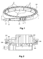
- Figure 1 is a CAD-drawing representing a plastic clamp according to a first particular embodiment of the present invention.
- the plastic clamp (100) comprises a strip (1) equipped with a toothed section (2) and two heads (3, 4) formed onto the strip (1).
- the toothed section (2) comprises a tab (21) equipped with two series of teeth (22, 23).
- the first series of teeth (22) is used for pre-closing operation and the second series of teeth (23) is used for final closing operation. It is an advantage to have a flat section (i.e. section with no teeth) between the first and second series of teeth, since the pull force for intermediate closing of the plastic clamp (100) can be reduced.
- the heads (3, 4) are configured to receive and lock the tab (21).
- Each head (3, 4) accommodates complementary teeth (not illustrated) which cooperate with the first and second series of teeth (22, 23).
- the plastic clamp (100) comprises twelve internal mouths (5) regularly spaced along the strip (1). As illustrated, each internal mouth has a contact surface (51) having a conical like structure.
- the plastic clamp (100) comprises a plurality of ribs (6) placed between the internal mouths (5) and the strip (1).
- the plastic clamp (100) comprises six ribs (three on the top side and three other on the bottom side) per internal mouth.
- Figure 2 is a CAD-drawing representing a partial cross-section of a tank assembly according to a particular embodiment of the present invention.
- the tank assembly comprises a tank having a wall portion (201) and a tubular attachment portion (202) projecting outward from said wall portion.
- the attachment portion (202) defines an opening (203) in the wall portion of the tank.
- the tank assembly further comprises a component (204) which is attached to the attachment portion (202) by means of the plastic clamp (100).
- the attachment portion (202) comprises a groove (205).
- An O ring seal (206) is arranged in the groove (205).
- the plastic clamp (100) is in a final closing position. Accordingly, the component (204) is tightly pressed against the attachment portion (202).
- the O ring seal (206) is compressed axially between the attachment portion (202) and the component (204).
- the tank (202) is a urea tank and the component (201) is a baseplate which incorporates and/or supports at least one active component such as, for example, a pump, a filter, a level sensor, a quality sensor, a temperature sensor or a heater. A part of this baseplate is positioned through the opening (203).
- Figures 3a to 3e illustrate an example of steps for attaching the component (204) to the attachment portion (202) by means of the plastic clamp 100.
- the O ring seal (206) is arranged in the groove (205).
- Figure 4 is a CAD-drawing representing a plastic clamp according to a second particular embodiment of the present invention.
- the plastic clamp (401) is used to attach a component (402) to a tank (406).
- the plastic clamp (401) comprises three extensions (403, 404, 405).
- Each extension is provided with an orifice (4031, 4041, 4051).
- These orifices can be used to attach, for example, a protection plate, some clips for hydraulic lines or wiring harnesses.
- these extensions (403, 404, 405) can advantageously be used as fixation points.
Landscapes
- Engineering & Computer Science (AREA)
- Mechanical Engineering (AREA)
- Life Sciences & Earth Sciences (AREA)
- Sustainable Development (AREA)
- Sustainable Energy (AREA)
- Chemical & Material Sciences (AREA)
- Combustion & Propulsion (AREA)
- Transportation (AREA)
- Cooling, Air Intake And Gas Exhaust, And Fuel Tank Arrangements In Propulsion Units (AREA)
Priority Applications (1)
| Application Number | Priority Date | Filing Date | Title |
|---|---|---|---|
| EP14166185.0A EP2939859A1 (de) | 2014-04-28 | 2014-04-28 | System zur Befestigung einer Komponente an einen Behälter für ein Kraftfahrzeug |
Applications Claiming Priority (1)
| Application Number | Priority Date | Filing Date | Title |
|---|---|---|---|
| EP14166185.0A EP2939859A1 (de) | 2014-04-28 | 2014-04-28 | System zur Befestigung einer Komponente an einen Behälter für ein Kraftfahrzeug |
Publications (1)
| Publication Number | Publication Date |
|---|---|
| EP2939859A1 true EP2939859A1 (de) | 2015-11-04 |
Family
ID=50555086
Family Applications (1)
| Application Number | Title | Priority Date | Filing Date |
|---|---|---|---|
| EP14166185.0A Withdrawn EP2939859A1 (de) | 2014-04-28 | 2014-04-28 | System zur Befestigung einer Komponente an einen Behälter für ein Kraftfahrzeug |
Country Status (1)
| Country | Link |
|---|---|
| EP (1) | EP2939859A1 (de) |
Citations (6)
| Publication number | Priority date | Publication date | Assignee | Title |
|---|---|---|---|---|
| US3339247A (en) * | 1965-08-17 | 1967-09-05 | Thomas & Betts Corp | Self-clinching bundling strap |
| US6332555B1 (en) * | 1996-07-06 | 2001-12-25 | Kautex Textron Gmbh & Co. Kg. | Fuel tank with opening closed by removable holding cover and sealing ring |
| US20060097524A1 (en) * | 2004-11-09 | 2006-05-11 | Stolzman Michael D | One piece locking belt |
| EP2058242A1 (de) * | 2007-11-07 | 2009-05-13 | Newfrey LLC | Befestigungselement zum Befestigen an einem Bolzen |
| DE102007059826A1 (de) * | 2007-12-11 | 2009-06-18 | Volkswagen Ag | Kraftstoff-Fördereinrichtung |
| US20130031751A1 (en) * | 2011-08-03 | 2013-02-07 | Thomas & Betts International, Inc. | Cable tie with improved pawl |
-
2014
- 2014-04-28 EP EP14166185.0A patent/EP2939859A1/de not_active Withdrawn
Patent Citations (6)
| Publication number | Priority date | Publication date | Assignee | Title |
|---|---|---|---|---|
| US3339247A (en) * | 1965-08-17 | 1967-09-05 | Thomas & Betts Corp | Self-clinching bundling strap |
| US6332555B1 (en) * | 1996-07-06 | 2001-12-25 | Kautex Textron Gmbh & Co. Kg. | Fuel tank with opening closed by removable holding cover and sealing ring |
| US20060097524A1 (en) * | 2004-11-09 | 2006-05-11 | Stolzman Michael D | One piece locking belt |
| EP2058242A1 (de) * | 2007-11-07 | 2009-05-13 | Newfrey LLC | Befestigungselement zum Befestigen an einem Bolzen |
| DE102007059826A1 (de) * | 2007-12-11 | 2009-06-18 | Volkswagen Ag | Kraftstoff-Fördereinrichtung |
| US20130031751A1 (en) * | 2011-08-03 | 2013-02-07 | Thomas & Betts International, Inc. | Cable tie with improved pawl |
Similar Documents
| Publication | Publication Date | Title |
|---|---|---|
| EP3026251A1 (de) | Anordnung mit verbessertem System zum Befestigen eines Bauteils an einem Behälter | |
| US8857643B2 (en) | Vessel for storing a fuel and/or operating medium for vehicles | |
| EP2167305B1 (de) | Verfahren zur befestigung eines zubehörs an einem brennstofftank aus kunststoff | |
| US9004415B2 (en) | Clamp | |
| EP3110648B1 (de) | Einfüllstutzengehäuse oder ladegehäuse | |
| US6843267B1 (en) | System and method for closing a tank opening | |
| EP3328672B1 (de) | Fahrzeugflüssigkeitstank mit befestigter komponente | |
| DE202011000201U1 (de) | SCR-Tank | |
| US12107291B2 (en) | Battery shell, traction battery and motor vehicle | |
| EP2939859A1 (de) | System zur Befestigung einer Komponente an einen Behälter für ein Kraftfahrzeug | |
| US20140209616A1 (en) | Cover with filler neck | |
| US9694830B2 (en) | Fastening arrangement for connecting an equipment container to a rail vehicle roof, and rail vehicle equipped therewith | |
| US9016499B2 (en) | Adapter for an oil filler neck and assembly method for the adapter | |
| US4212318A (en) | Retainer assembly for fuel tank mounted sending unit | |
| US8167343B2 (en) | Device for attachment of a bumper covering | |
| KR20180077155A (ko) | 강화 장치를 가진 용기 | |
| US11894582B2 (en) | Stopper for closing and sealing an opening in a housing of an energy storage system and energy storage system | |
| EP3052335B1 (de) | Behälter mit innerem verbindungsteil und verfahren zur montage eines solchen behälters | |
| JP4490156B2 (ja) | グロメット | |
| DE102010039495A1 (de) | Reduktionsmittel-Vorratsbehälter | |
| US7793894B1 (en) | Retaining system | |
| CN111717007A (zh) | 夹子锁块装置 | |
| JP3227716U (ja) | 自動車で使用するための一時保護装置 | |
| US20090309348A1 (en) | Process for producing a fuel tank with underride protector | |
| WO2018232519A1 (en) | EXPANDABLE TANK ASSEMBLY |
Legal Events
| Date | Code | Title | Description |
|---|---|---|---|
| PUAI | Public reference made under article 153(3) epc to a published international application that has entered the european phase |
Free format text: ORIGINAL CODE: 0009012 |
|
| AK | Designated contracting states |
Kind code of ref document: A1 Designated state(s): AL AT BE BG CH CY CZ DE DK EE ES FI FR GB GR HR HU IE IS IT LI LT LU LV MC MK MT NL NO PL PT RO RS SE SI SK SM TR |
|
| AX | Request for extension of the european patent |
Extension state: BA ME |
|
| STAA | Information on the status of an ep patent application or granted ep patent |
Free format text: STATUS: THE APPLICATION IS DEEMED TO BE WITHDRAWN |
|
| 18D | Application deemed to be withdrawn |
Effective date: 20160505 |