EP2939833A1 - Inkjet printing device and inkjet printing method - Google Patents
Inkjet printing device and inkjet printing method Download PDFInfo
- Publication number
- EP2939833A1 EP2939833A1 EP13868469.1A EP13868469A EP2939833A1 EP 2939833 A1 EP2939833 A1 EP 2939833A1 EP 13868469 A EP13868469 A EP 13868469A EP 2939833 A1 EP2939833 A1 EP 2939833A1
- Authority
- EP
- European Patent Office
- Prior art keywords
- inks
- inkjet
- ink
- medium
- inkjet heads
- Prior art date
- Legal status (The legal status is an assumption and is not a legal conclusion. Google has not performed a legal analysis and makes no representation as to the accuracy of the status listed.)
- Withdrawn
Links
- 238000007641 inkjet printing Methods 0.000 title claims abstract description 73
- 238000000034 method Methods 0.000 title claims description 13
- 239000000976 ink Substances 0.000 claims abstract description 264
- 238000010438 heat treatment Methods 0.000 claims abstract description 61
- 239000003086 colorant Substances 0.000 claims abstract description 39
- 238000011144 upstream manufacturing Methods 0.000 claims description 17
- 238000007599 discharging Methods 0.000 claims description 10
- 239000002904 solvent Substances 0.000 description 36
- 229920005989 resin Polymers 0.000 description 29
- 239000011347 resin Substances 0.000 description 29
- 239000004816 latex Substances 0.000 description 15
- 229920000126 latex Polymers 0.000 description 15
- 239000000178 monomer Substances 0.000 description 8
- 230000005855 radiation Effects 0.000 description 8
- 238000001723 curing Methods 0.000 description 7
- XLYOFNOQVPJJNP-UHFFFAOYSA-N water Substances O XLYOFNOQVPJJNP-UHFFFAOYSA-N 0.000 description 7
- 208000032843 Hemorrhage Diseases 0.000 description 5
- 208000034158 bleeding Diseases 0.000 description 5
- 230000000740 bleeding effect Effects 0.000 description 5
- 229920000178 Acrylic resin Polymers 0.000 description 4
- 239000004925 Acrylic resin Substances 0.000 description 4
- 238000001816 cooling Methods 0.000 description 4
- 239000003960 organic solvent Substances 0.000 description 4
- 239000002245 particle Substances 0.000 description 4
- ZWEHNKRNPOVVGH-UHFFFAOYSA-N 2-Butanone Chemical compound CCC(C)=O ZWEHNKRNPOVVGH-UHFFFAOYSA-N 0.000 description 3
- UHOVQNZJYSORNB-UHFFFAOYSA-N Benzene Chemical compound C1=CC=CC=C1 UHOVQNZJYSORNB-UHFFFAOYSA-N 0.000 description 3
- XEKOWRVHYACXOJ-UHFFFAOYSA-N Ethyl acetate Chemical compound CCOC(C)=O XEKOWRVHYACXOJ-UHFFFAOYSA-N 0.000 description 3
- IMNFDUFMRHMDMM-UHFFFAOYSA-N N-Heptane Chemical compound CCCCCCC IMNFDUFMRHMDMM-UHFFFAOYSA-N 0.000 description 3
- YXFVVABEGXRONW-UHFFFAOYSA-N Toluene Chemical compound CC1=CC=CC=C1 YXFVVABEGXRONW-UHFFFAOYSA-N 0.000 description 3
- DKPFZGUDAPQIHT-UHFFFAOYSA-N butyl acetate Chemical compound CCCCOC(C)=O DKPFZGUDAPQIHT-UHFFFAOYSA-N 0.000 description 3
- 238000001035 drying Methods 0.000 description 3
- 230000007613 environmental effect Effects 0.000 description 3
- 230000002070 germicidal effect Effects 0.000 description 3
- -1 glycol ethers Chemical class 0.000 description 3
- 230000001678 irradiating effect Effects 0.000 description 3
- 229910001507 metal halide Inorganic materials 0.000 description 3
- 150000005309 metal halides Chemical class 0.000 description 3
- 238000007639 printing Methods 0.000 description 3
- 229910052724 xenon Inorganic materials 0.000 description 3
- FHNFHKCVQCLJFQ-UHFFFAOYSA-N xenon atom Chemical compound [Xe] FHNFHKCVQCLJFQ-UHFFFAOYSA-N 0.000 description 3
- QQZOPKMRPOGIEB-UHFFFAOYSA-N 2-Oxohexane Chemical compound CCCCC(C)=O QQZOPKMRPOGIEB-UHFFFAOYSA-N 0.000 description 2
- YEJRWHAVMIAJKC-UHFFFAOYSA-N 4-Butyrolactone Chemical group O=C1CCCO1 YEJRWHAVMIAJKC-UHFFFAOYSA-N 0.000 description 2
- HCFAJYNVAYBARA-UHFFFAOYSA-N 4-heptanone Chemical compound CCCC(=O)CCC HCFAJYNVAYBARA-UHFFFAOYSA-N 0.000 description 2
- 239000004215 Carbon black (E152) Substances 0.000 description 2
- YNQLUTRBYVCPMQ-UHFFFAOYSA-N Ethylbenzene Chemical compound CCC1=CC=CC=C1 YNQLUTRBYVCPMQ-UHFFFAOYSA-N 0.000 description 2
- CTQNGGLPUBDAKN-UHFFFAOYSA-N O-Xylene Chemical group CC1=CC=CC=C1C CTQNGGLPUBDAKN-UHFFFAOYSA-N 0.000 description 2
- URLKBWYHVLBVBO-UHFFFAOYSA-N Para-Xylene Chemical group CC1=CC=C(C)C=C1 URLKBWYHVLBVBO-UHFFFAOYSA-N 0.000 description 2
- NMJJFJNHVMGPGM-UHFFFAOYSA-N butyl formate Chemical compound CCCCOC=O NMJJFJNHVMGPGM-UHFFFAOYSA-N 0.000 description 2
- 238000010894 electron beam technology Methods 0.000 description 2
- 239000003759 ester based solvent Substances 0.000 description 2
- FKRCODPIKNYEAC-UHFFFAOYSA-N ethyl propionate Chemical group CCOC(=O)CC FKRCODPIKNYEAC-UHFFFAOYSA-N 0.000 description 2
- XLLIQLLCWZCATF-UHFFFAOYSA-N ethylene glycol monomethyl ether acetate Natural products COCCOC(C)=O XLLIQLLCWZCATF-UHFFFAOYSA-N 0.000 description 2
- NGAZZOYFWWSOGK-UHFFFAOYSA-N heptan-3-one Chemical compound CCCCC(=O)CC NGAZZOYFWWSOGK-UHFFFAOYSA-N 0.000 description 2
- AOGQPLXWSUTHQB-UHFFFAOYSA-N hexyl acetate Chemical group CCCCCCOC(C)=O AOGQPLXWSUTHQB-UHFFFAOYSA-N 0.000 description 2
- 229930195733 hydrocarbon Natural products 0.000 description 2
- 150000002430 hydrocarbons Chemical class 0.000 description 2
- MLFHJEHSLIIPHL-UHFFFAOYSA-N isoamyl acetate Chemical group CC(C)CCOC(C)=O MLFHJEHSLIIPHL-UHFFFAOYSA-N 0.000 description 2
- 239000005453 ketone based solvent Substances 0.000 description 2
- IVSZLXZYQVIEFR-UHFFFAOYSA-N m-xylene Chemical group CC1=CC=CC(C)=C1 IVSZLXZYQVIEFR-UHFFFAOYSA-N 0.000 description 2
- 239000000463 material Substances 0.000 description 2
- UAEPNZWRGJTJPN-UHFFFAOYSA-N methylcyclohexane Chemical compound CC1CCCCC1 UAEPNZWRGJTJPN-UHFFFAOYSA-N 0.000 description 2
- VLKZOEOYAKHREP-UHFFFAOYSA-N n-Hexane Chemical compound CCCCCC VLKZOEOYAKHREP-UHFFFAOYSA-N 0.000 description 2
- TVMXDCGIABBOFY-UHFFFAOYSA-N octane Chemical compound CCCCCCCC TVMXDCGIABBOFY-UHFFFAOYSA-N 0.000 description 2
- XNLICIUVMPYHGG-UHFFFAOYSA-N pentan-2-one Chemical compound CCCC(C)=O XNLICIUVMPYHGG-UHFFFAOYSA-N 0.000 description 2
- FDPIMTJIUBPUKL-UHFFFAOYSA-N pentan-3-one Chemical compound CCC(=O)CC FDPIMTJIUBPUKL-UHFFFAOYSA-N 0.000 description 2
- PGMYKACGEOXYJE-UHFFFAOYSA-N pentyl acetate Chemical group CCCCCOC(C)=O PGMYKACGEOXYJE-UHFFFAOYSA-N 0.000 description 2
- 229920001225 polyester resin Polymers 0.000 description 2
- 229920002635 polyurethane Polymers 0.000 description 2
- 239000004814 polyurethane Substances 0.000 description 2
- YKYONYBAUNKHLG-UHFFFAOYSA-N propyl acetate Chemical compound CCCOC(C)=O YKYONYBAUNKHLG-UHFFFAOYSA-N 0.000 description 2
- OZXIZRZFGJZWBF-UHFFFAOYSA-N 1,3,5-trimethyl-2-(2,4,6-trimethylphenoxy)benzene Chemical compound CC1=CC(C)=CC(C)=C1OC1=C(C)C=C(C)C=C1C OZXIZRZFGJZWBF-UHFFFAOYSA-N 0.000 description 1
- HNAGHMKIPMKKBB-UHFFFAOYSA-N 1-benzylpyrrolidine-3-carboxamide Chemical group C1C(C(=O)N)CCN1CC1=CC=CC=C1 HNAGHMKIPMKKBB-UHFFFAOYSA-N 0.000 description 1
- ARXJGSRGQADJSQ-UHFFFAOYSA-N 1-methoxypropan-2-ol Chemical compound COCC(C)O ARXJGSRGQADJSQ-UHFFFAOYSA-N 0.000 description 1
- UJXNFMNODANVBL-UHFFFAOYSA-N 1-methoxypropan-2-yl butanoate Chemical compound CCCC(=O)OC(C)COC UJXNFMNODANVBL-UHFFFAOYSA-N 0.000 description 1
- DOVZUKKPYKRVIK-UHFFFAOYSA-N 1-methoxypropan-2-yl propanoate Chemical compound CCC(=O)OC(C)COC DOVZUKKPYKRVIK-UHFFFAOYSA-N 0.000 description 1
- VXQBJTKSVGFQOL-UHFFFAOYSA-N 2-(2-butoxyethoxy)ethyl acetate Chemical compound CCCCOCCOCCOC(C)=O VXQBJTKSVGFQOL-UHFFFAOYSA-N 0.000 description 1
- UWAALKSFUOKZEZ-UHFFFAOYSA-N 2-(2-butoxyethoxy)ethyl butanoate Chemical compound CCCCOCCOCCOC(=O)CCC UWAALKSFUOKZEZ-UHFFFAOYSA-N 0.000 description 1
- ATBZPVUIQSIQEQ-UHFFFAOYSA-N 2-(2-butoxyethoxy)ethyl propanoate Chemical compound CCCCOCCOCCOC(=O)CC ATBZPVUIQSIQEQ-UHFFFAOYSA-N 0.000 description 1
- FPZWZCWUIYYYBU-UHFFFAOYSA-N 2-(2-ethoxyethoxy)ethyl acetate Chemical compound CCOCCOCCOC(C)=O FPZWZCWUIYYYBU-UHFFFAOYSA-N 0.000 description 1
- LSZXZWOYLFWMCZ-UHFFFAOYSA-N 2-(2-ethoxyethoxy)ethyl butanoate Chemical compound CCCC(=O)OCCOCCOCC LSZXZWOYLFWMCZ-UHFFFAOYSA-N 0.000 description 1
- WVQBWABPJKXSRL-UHFFFAOYSA-N 2-(2-ethoxyethoxy)ethyl propanoate Chemical compound CCOCCOCCOC(=O)CC WVQBWABPJKXSRL-UHFFFAOYSA-N 0.000 description 1
- BJINVQNEBGOMCR-UHFFFAOYSA-N 2-(2-methoxyethoxy)ethyl acetate Chemical compound COCCOCCOC(C)=O BJINVQNEBGOMCR-UHFFFAOYSA-N 0.000 description 1
- LFXBTVJAXBBHDZ-UHFFFAOYSA-N 2-(2-methoxyethoxy)ethyl butanoate Chemical compound CCCC(=O)OCCOCCOC LFXBTVJAXBBHDZ-UHFFFAOYSA-N 0.000 description 1
- ZQYZWKKVGVACJM-UHFFFAOYSA-N 2-(2-methoxyethoxy)ethyl propanoate Chemical compound CCC(=O)OCCOCCOC ZQYZWKKVGVACJM-UHFFFAOYSA-N 0.000 description 1
- DRLRGHZJOQGQEC-UHFFFAOYSA-N 2-(2-methoxypropoxy)propyl acetate Chemical compound COC(C)COC(C)COC(C)=O DRLRGHZJOQGQEC-UHFFFAOYSA-N 0.000 description 1
- IZXZMWGHPXBDNQ-UHFFFAOYSA-N 2-(2-methoxypropoxy)propyl butanoate Chemical compound CCCC(=O)OCC(C)OCC(C)OC IZXZMWGHPXBDNQ-UHFFFAOYSA-N 0.000 description 1
- NVSZPGYVYSDFEV-UHFFFAOYSA-N 2-(2-methoxypropoxy)propyl propanoate Chemical compound CCC(=O)OCC(C)OCC(C)OC NVSZPGYVYSDFEV-UHFFFAOYSA-N 0.000 description 1
- AVMSWPWPYJVYKY-UHFFFAOYSA-N 2-Methylpropyl formate Chemical compound CC(C)COC=O AVMSWPWPYJVYKY-UHFFFAOYSA-N 0.000 description 1
- NQBXSWAWVZHKBZ-UHFFFAOYSA-N 2-butoxyethyl acetate Chemical compound CCCCOCCOC(C)=O NQBXSWAWVZHKBZ-UHFFFAOYSA-N 0.000 description 1
- JWIUNFHJMLAEPS-UHFFFAOYSA-N 2-butoxyethyl butanoate Chemical compound CCCCOCCOC(=O)CCC JWIUNFHJMLAEPS-UHFFFAOYSA-N 0.000 description 1
- IYVJUFDNYUMRAB-UHFFFAOYSA-N 2-butoxyethyl propanoate Chemical compound CCCCOCCOC(=O)CC IYVJUFDNYUMRAB-UHFFFAOYSA-N 0.000 description 1
- SVONRAPFKPVNKG-UHFFFAOYSA-N 2-ethoxyethyl acetate Chemical compound CCOCCOC(C)=O SVONRAPFKPVNKG-UHFFFAOYSA-N 0.000 description 1
- RUCPXHYWYFCCOY-UHFFFAOYSA-N 2-ethoxyethyl butanoate Chemical compound CCCC(=O)OCCOCC RUCPXHYWYFCCOY-UHFFFAOYSA-N 0.000 description 1
- BYVKCQBOHJQWIO-UHFFFAOYSA-N 2-ethoxyethyl propanoate Chemical compound CCOCCOC(=O)CC BYVKCQBOHJQWIO-UHFFFAOYSA-N 0.000 description 1
- XGNMYOSGLQVPFQ-UHFFFAOYSA-N 2-methoxyethyl butanoate Chemical compound CCCC(=O)OCCOC XGNMYOSGLQVPFQ-UHFFFAOYSA-N 0.000 description 1
- VAHNPAMCADTGIO-UHFFFAOYSA-N 2-methoxyethyl propanoate Chemical compound CCC(=O)OCCOC VAHNPAMCADTGIO-UHFFFAOYSA-N 0.000 description 1
- CPIVYSAVIPTCCX-UHFFFAOYSA-N 4-methylpentan-2-yl acetate Chemical group CC(C)CC(C)OC(C)=O CPIVYSAVIPTCCX-UHFFFAOYSA-N 0.000 description 1
- LPEKGGXMPWTOCB-UHFFFAOYSA-N 8beta-(2,3-epoxy-2-methylbutyryloxy)-14-acetoxytithifolin Chemical group COC(=O)C(C)O LPEKGGXMPWTOCB-UHFFFAOYSA-N 0.000 description 1
- FERIUCNNQQJTOY-UHFFFAOYSA-M Butyrate Chemical compound CCCC([O-])=O FERIUCNNQQJTOY-UHFFFAOYSA-M 0.000 description 1
- XDTMQSROBMDMFD-UHFFFAOYSA-N Cyclohexane Chemical compound C1CCCCC1 XDTMQSROBMDMFD-UHFFFAOYSA-N 0.000 description 1
- 239000004593 Epoxy Substances 0.000 description 1
- NHTMVDHEPJAVLT-UHFFFAOYSA-N Isooctane Chemical compound CC(C)CC(C)(C)C NHTMVDHEPJAVLT-UHFFFAOYSA-N 0.000 description 1
- JGFBQFKZKSSODQ-UHFFFAOYSA-N Isothiocyanatocyclopropane Chemical group S=C=NC1CC1 JGFBQFKZKSSODQ-UHFFFAOYSA-N 0.000 description 1
- NTIZESTWPVYFNL-UHFFFAOYSA-N Methyl isobutyl ketone Chemical compound CC(C)CC(C)=O NTIZESTWPVYFNL-UHFFFAOYSA-N 0.000 description 1
- UIHCLUNTQKBZGK-UHFFFAOYSA-N Methyl isobutyl ketone Natural products CCC(C)C(C)=O UIHCLUNTQKBZGK-UHFFFAOYSA-N 0.000 description 1
- RJUFJBKOKNCXHH-UHFFFAOYSA-N Methyl propionate Chemical group CCC(=O)OC RJUFJBKOKNCXHH-UHFFFAOYSA-N 0.000 description 1
- DIQMPQMYFZXDAX-UHFFFAOYSA-N Pentyl formate Chemical compound CCCCCOC=O DIQMPQMYFZXDAX-UHFFFAOYSA-N 0.000 description 1
- 241001274961 Rubus repens Species 0.000 description 1
- XUIMIQQOPSSXEZ-UHFFFAOYSA-N Silicon Chemical compound [Si] XUIMIQQOPSSXEZ-UHFFFAOYSA-N 0.000 description 1
- BZHJMEDXRYGGRV-UHFFFAOYSA-N Vinyl chloride Chemical compound ClC=C BZHJMEDXRYGGRV-UHFFFAOYSA-N 0.000 description 1
- 229920000180 alkyd Polymers 0.000 description 1
- 239000007900 aqueous suspension Substances 0.000 description 1
- OBNCKNCVKJNDBV-UHFFFAOYSA-N butanoic acid ethyl ester Chemical group CCCC(=O)OCC OBNCKNCVKJNDBV-UHFFFAOYSA-N 0.000 description 1
- QHIWVLPBUQWDMQ-UHFFFAOYSA-N butyl prop-2-enoate;methyl 2-methylprop-2-enoate;prop-2-enoic acid Chemical compound OC(=O)C=C.COC(=O)C(C)=C.CCCCOC(=O)C=C QHIWVLPBUQWDMQ-UHFFFAOYSA-N 0.000 description 1
- BTMVHUNTONAYDX-UHFFFAOYSA-N butyl propionate Chemical group CCCCOC(=O)CC BTMVHUNTONAYDX-UHFFFAOYSA-N 0.000 description 1
- PWLNAUNEAKQYLH-UHFFFAOYSA-N butyric acid octyl ester Chemical group CCCCCCCCOC(=O)CCC PWLNAUNEAKQYLH-UHFFFAOYSA-N 0.000 description 1
- JVSWJIKNEAIKJW-UHFFFAOYSA-N dimethyl-hexane Natural products CCCCCC(C)C JVSWJIKNEAIKJW-UHFFFAOYSA-N 0.000 description 1
- ODQWQRRAPPTVAG-GZTJUZNOSA-N doxepin Chemical group C1OC2=CC=CC=C2C(=C/CCN(C)C)/C2=CC=CC=C21 ODQWQRRAPPTVAG-GZTJUZNOSA-N 0.000 description 1
- 230000000694 effects Effects 0.000 description 1
- 238000001227 electron beam curing Methods 0.000 description 1
- 239000003995 emulsifying agent Substances 0.000 description 1
- 230000001804 emulsifying effect Effects 0.000 description 1
- 239000000839 emulsion Substances 0.000 description 1
- LYCAIKOWRPUZTN-UHFFFAOYSA-N ethylene glycol Natural products OCCO LYCAIKOWRPUZTN-UHFFFAOYSA-N 0.000 description 1
- 238000001704 evaporation Methods 0.000 description 1
- 238000009499 grossing Methods 0.000 description 1
- FUZZWVXGSFPDMH-UHFFFAOYSA-N hexanoic acid Chemical group CCCCCC(O)=O FUZZWVXGSFPDMH-UHFFFAOYSA-N 0.000 description 1
- WGCNASOHLSPBMP-UHFFFAOYSA-N hydroxyacetaldehyde Natural products OCC=O WGCNASOHLSPBMP-UHFFFAOYSA-N 0.000 description 1
- GJRQTCIYDGXPES-UHFFFAOYSA-N iso-butyl acetate Natural products CC(C)COC(C)=O GJRQTCIYDGXPES-UHFFFAOYSA-N 0.000 description 1
- 229940117955 isoamyl acetate Drugs 0.000 description 1
- FGKJLKRYENPLQH-UHFFFAOYSA-M isocaproate Chemical compound CC(C)CCC([O-])=O FGKJLKRYENPLQH-UHFFFAOYSA-M 0.000 description 1
- JMMWKPVZQRWMSS-UHFFFAOYSA-N isopropanol acetate Natural products CC(C)OC(C)=O JMMWKPVZQRWMSS-UHFFFAOYSA-N 0.000 description 1
- 229940011051 isopropyl acetate Drugs 0.000 description 1
- GWYFCOCPABKNJV-UHFFFAOYSA-N isovaleric acid Chemical compound CC(C)CC(O)=O GWYFCOCPABKNJV-UHFFFAOYSA-N 0.000 description 1
- OQAGVSWESNCJJT-UHFFFAOYSA-N isovaleric acid methyl ester Natural products COC(=O)CC(C)C OQAGVSWESNCJJT-UHFFFAOYSA-N 0.000 description 1
- SHOJXDKTYKFBRD-UHFFFAOYSA-N mesityl oxide Natural products CC(C)=CC(C)=O SHOJXDKTYKFBRD-UHFFFAOYSA-N 0.000 description 1
- 229940057867 methyl lactate Drugs 0.000 description 1
- 229940017219 methyl propionate Drugs 0.000 description 1
- GYNNXHKOJHMOHS-UHFFFAOYSA-N methyl-cycloheptane Natural products CC1CCCCCC1 GYNNXHKOJHMOHS-UHFFFAOYSA-N 0.000 description 1
- 238000012986 modification Methods 0.000 description 1
- 230000004048 modification Effects 0.000 description 1
- UUIQMZJEGPQKFD-UHFFFAOYSA-N n-butyric acid methyl ester Chemical group CCCC(=O)OC UUIQMZJEGPQKFD-UHFFFAOYSA-N 0.000 description 1
- 229940078552 o-xylene Drugs 0.000 description 1
- 125000000951 phenoxy group Chemical group [H]C1=C([H])C([H])=C(O*)C([H])=C1[H] 0.000 description 1
- 229920005672 polyolefin resin Polymers 0.000 description 1
- LLHKCFNBLRBOGN-UHFFFAOYSA-N propylene glycol methyl ether acetate Chemical compound COCC(C)OC(C)=O LLHKCFNBLRBOGN-UHFFFAOYSA-N 0.000 description 1
- 230000001681 protective effect Effects 0.000 description 1
- 239000010703 silicon Substances 0.000 description 1
- 229910052710 silicon Inorganic materials 0.000 description 1
- 125000000391 vinyl group Chemical group [H]C([*])=C([H])[H] 0.000 description 1
- 229920002554 vinyl polymer Polymers 0.000 description 1
Images

Classifications
-
- B—PERFORMING OPERATIONS; TRANSPORTING
- B41—PRINTING; LINING MACHINES; TYPEWRITERS; STAMPS
- B41J—TYPEWRITERS; SELECTIVE PRINTING MECHANISMS, i.e. MECHANISMS PRINTING OTHERWISE THAN FROM A FORME; CORRECTION OF TYPOGRAPHICAL ERRORS
- B41J11/00—Devices or arrangements of selective printing mechanisms, e.g. ink-jet printers or thermal printers, for supporting or handling copy material in sheet or web form
- B41J11/0015—Devices or arrangements of selective printing mechanisms, e.g. ink-jet printers or thermal printers, for supporting or handling copy material in sheet or web form for treating before, during or after printing or for uniform coating or laminating the copy material before or after printing
- B41J11/002—Curing or drying the ink on the copy materials, e.g. by heating or irradiating
-
- B—PERFORMING OPERATIONS; TRANSPORTING
- B41—PRINTING; LINING MACHINES; TYPEWRITERS; STAMPS
- B41J—TYPEWRITERS; SELECTIVE PRINTING MECHANISMS, i.e. MECHANISMS PRINTING OTHERWISE THAN FROM A FORME; CORRECTION OF TYPOGRAPHICAL ERRORS
- B41J11/00—Devices or arrangements of selective printing mechanisms, e.g. ink-jet printers or thermal printers, for supporting or handling copy material in sheet or web form
- B41J11/0015—Devices or arrangements of selective printing mechanisms, e.g. ink-jet printers or thermal printers, for supporting or handling copy material in sheet or web form for treating before, during or after printing or for uniform coating or laminating the copy material before or after printing
- B41J11/002—Curing or drying the ink on the copy materials, e.g. by heating or irradiating
- B41J11/0021—Curing or drying the ink on the copy materials, e.g. by heating or irradiating using irradiation
- B41J11/00214—Curing or drying the ink on the copy materials, e.g. by heating or irradiating using irradiation using UV radiation
-
- B—PERFORMING OPERATIONS; TRANSPORTING
- B41—PRINTING; LINING MACHINES; TYPEWRITERS; STAMPS
- B41J—TYPEWRITERS; SELECTIVE PRINTING MECHANISMS, i.e. MECHANISMS PRINTING OTHERWISE THAN FROM A FORME; CORRECTION OF TYPOGRAPHICAL ERRORS
- B41J11/00—Devices or arrangements of selective printing mechanisms, e.g. ink-jet printers or thermal printers, for supporting or handling copy material in sheet or web form
- B41J11/0015—Devices or arrangements of selective printing mechanisms, e.g. ink-jet printers or thermal printers, for supporting or handling copy material in sheet or web form for treating before, during or after printing or for uniform coating or laminating the copy material before or after printing
- B41J11/002—Curing or drying the ink on the copy materials, e.g. by heating or irradiating
- B41J11/0022—Curing or drying the ink on the copy materials, e.g. by heating or irradiating using convection means, e.g. by using a fan for blowing or sucking air
-
- B—PERFORMING OPERATIONS; TRANSPORTING
- B41—PRINTING; LINING MACHINES; TYPEWRITERS; STAMPS
- B41J—TYPEWRITERS; SELECTIVE PRINTING MECHANISMS, i.e. MECHANISMS PRINTING OTHERWISE THAN FROM A FORME; CORRECTION OF TYPOGRAPHICAL ERRORS
- B41J11/00—Devices or arrangements of selective printing mechanisms, e.g. ink-jet printers or thermal printers, for supporting or handling copy material in sheet or web form
- B41J11/0015—Devices or arrangements of selective printing mechanisms, e.g. ink-jet printers or thermal printers, for supporting or handling copy material in sheet or web form for treating before, during or after printing or for uniform coating or laminating the copy material before or after printing
Definitions
- the present invention relates to an inkjet printing device and an inkjet printing method.
- Patent Document 1 describes a printer equipped with a pre-heater for preheating an unprinted medium, and a print-heater for heating the medium with an object just printed thereon.
- Patent Document 1 Japanese Patent Application Laid-Open No. 2010-30313 A (disclosed on February 12, 2010)
- serial inkjet printer described in Patent Document 1 has an unsolved problem; smearing of ink discharged on the medium through an inkjet head may degrade the quality of a printed image.
- the invention has been accomplished to solve this problem, and has an object to provide an inkjet printing device and an inkjet printing method by which high-quality printing is fulfilled.
- an inkjet printing device includes: a transferring unit for transferring a print medium; an inkjet head for discharging an ink on the print medium to carry out a print job; a print-heater for heating the print medium, the print-heater being disposed so as to face a region where the ink is discharged through the inkjet head with the print medium interposed therebetween; and an after-heater for heating the ink discharged on the print medium, the after-heater being installed on a downstream side in a direction of transfer of the print medium relative to the print-heater, wherein the inkjet printing device includes a plurality of inkjet heads as the inkjet head, and the plurality of inkjet heads discharges the inks in different colors and is aligned in the direction of transfer.
- the plural inkjet heads that respectively discharge the inks in different colors are aligned in the direction of transfer. These inkjet heads thus aligned in the direction of transfer discharge the respective inks in a sequential order on the print medium while being transferred. While one of the inkjet heads is discharging its ink on the print medium, the ink discharged and adhered to the print medium is heated by the print-heater. When another one of the inkjet heads starts to discharge its ink on the print medium, the ink previously discharged and adhered to the print medium has already been thickened to a given or higher degree of viscosity. This ink, therefore, has no chance of smearing.
- the inks on the print medium can provide a high-quality print.
- the inkjet printing device is further characterized in that, of the plurality of inkjet heads, the inkjet heads that discharge the inks in any colors but black are arranged from an upstream side toward the downstream side in the direction of transfer, so that the inks in different colors are discharged through the inkjet heads in the order of lower clarity.
- the plural inkjet heads discharge the inks in any colors but black in the order of lower clarity from the upstream side toward the downstream side in the direction of transfer of the print medium. Therefore, the ink of higher clarity is discharged on the ink of lower clarity. This prevents that incident light is reflected or absorbed by an ink surface alone, allowing the inks to exhibit their colors more vividly.
- the inkjet printing device is further characterized in that the plurality of inkjet heads is at least four inkjet heads that are aligned along the direction of transfer, and the four inkjet heads are arranged from the upstream side toward the downstream side in the direction of transfer so as to respectively discharge cyan, magenta, yellow, and black inks in a sequential order.
- the inkjet printing device thus characterized discharges the different color inks except the black ink in the order of lower clarity. This allows the inks to exhibit their colors more vividly.
- the plural inkjet heads may be spaced at intervals optionally decided depending on such factors as transfer speed of the print medium, types of used inks, type of the print medium, heating temperatures, and environmental temperature.
- the inkjet printing device is further characterized in that the plurality of inkjet heads, facing the print medium, moves in a direction intersecting the direction of transfer, the plurality of inkjet heads is at least four inkjet heads, two of the four inkjet heads are aligned in the direction intersecting the direction of transfer, other two of the four inkjet heads are located on the upstream side in the direction of transfer relative to the two of the four inkjet heads aligned in the direction intersecting the direction of transfer, and the two of the four inkjet heads on the downstream side in the direction of transfer respectively discharge the yellow and black inks.
- the serial head inkjet printing device can be compactly structured as compared to disposing plurality of the inkjet heads along the direction of transfer.
- An inkjet printing method includes: a transfer step of transferring a print medium; a print step of discharging an ink on a print medium through an inkjet head to carry out a print job; a first heating step of heating the print medium facing a region where the ink is discharged through the inkjet head; and a second heating step of heating the ink on the print medium transferred subsequent to the first heating step, wherein a plurality of inkjet heads is provided as the inkjet head, and the plurality of inkjet heads discharges the inks in different colors and is aligned in a direction of transfer of the print medium.
- the inkjet printing method according to the invention provides similar technical advantages to those provided by the inkjet printing device according to the invention.
- the inkjet printing device and the inkjet printing method according to the invention can both advantageously fulfill high-speed and high-quality printing.
- FIG. 1 is a drawing of an inkjet printing device according to the embodiment.
- An inkjet printing device 100 includes: a transferring roller (transferring unit, not illustrated) for transferring a medium (print medium) 20; inkjet heads 2 to 5 that respectively discharge inks on the medium 20 to carry out a print job; a print-heater 6 for heating the medium 20, the print-heater 6 being disposed so as to face a region where the inks are discharged through the inkjet heads 2 to 5 with the medium 20 interposed therebetween; and an after-heater 7 for heating the inks discharged on the medium 20, the after-heater 7 being installed on a downstream side in a direction of transfer of the medium 20 (direction indicated by arrow X in FIG. 1 ) relative to the print-heater 6.
- a transferring roller for transferring a medium (print medium) 20
- inkjet heads 2 to 5 that respectively discharge inks on the medium 20 to carry out a print job
- a print-heater 6 for heating the medium 20, the print-heater 6 being disposed so as to
- the plural inkjet heads 2 to 5 respectively discharge the inks in different colors and are aligned in the direction of transfer.
- the inkjet printing device 100 according to the embodiment further includes a take-up roll 1, a fan 8, ultraviolet emitting lamps 10 to 12, and a warm/hot air heater 9. If smearing of the inks can be prevented by the print-heater 6 alone, the ultraviolet emitting lamps 10 and 11 may be unnecessary.
- the inkjet printing device 100 is configured to discharge inks on the medium 20 to obtain a print object inkjet-printed thereon.
- Examples of the inkjet printing device according to the invention are serial head inkjet printing device, and line head inkjet printing device.
- the printer of the former type has movable inkjet heads and discharges inks on a print medium through the heads moving in a direction intersecting a direction of transfer of the print medium.
- the printer of the latter type has relatively long and stationary inkjet heads and discharges inks through the heads on the print medium while being transferred.
- the transferring roller for transferring the medium 20 is installed on the downstream or upstream side in the direction of transfer in vicinity of a region where the medium 20 is printed. By driving the transferring roller, the medium 20 is transferred by a frictional force generated by the roller.
- the take-up roll 1 winds the medium 20 around its outer periphery to retrieve the printed medium 20 in the form of a roll.
- the take-up roll 1 is located on the downstream side in the direction of transfer of the medium 20.
- the inkjet heads 2 to 5 discharge inks on the medium 20 to print an object thereon.
- the inkjet heads 2 to 5 discharge inks in different colors and are aligned in the direction of transfer of the medium 20.
- the inkjet heads 2 to 5 are aligned along the direction of transfer of the medium 20 (direction indicated by arrow X in FIG. 1 ).
- the inkjet heads 2 to 5 are arranged from the upstream side toward the downstream side in the direction of transfer so as to respectively discharge cyan, magenta, yellow, and black inks in a sequential order.
- the inkjet head 2 discharges the cyan ink
- the inkjet head 3 discharges the magenta ink
- the inkjet head 4 discharges the yellow ink
- the inkjet head 5 discharges the black ink.
- the inkjet heads 2 to 4 that discharge the color inks other than the black ink are preferably arranged from the upstream side toward the downstream side in the direction of transfer of the medium 20, so that the different color inks are discharged through these heads in the order of lower clarity.
- the inkjet printing device thus characterized discharges the different color inks except the black ink in the order of lower clarity, so that the inks of higher clarity are discharged on the inks of lower clarity. This prevents that incident light is reflected or absorbed by an ink surface alone, allowing the inks to exhibit their colors more vividly.
- the plural inkjet heads may be spaced at intervals optionally decided depending on such factors as transfer speed of the print medium, types of used inks, and type of the print medium, heating temperatures, and environmental temperature.
- the inkjet heads may be spaced from one another by a distance that the slowest-drying ink among all the inks heated by the print-heater 6 described later can be dry enough not to smear, or the inter-head intervals may be variable depending on the properties of the discharged inks.
- the inkjet head that discharges the black ink may be located on the upstream side or the downstream side relative to the other ink discharging jet heads.
- the inkjet printing device has any number more than one of inkjet heads that respectively discharge different color inks.
- the device may have a plurality of inkjet heads that discharge inks of the same color.
- colors of the inks used in the inkjet heads according to the invention include, but are not limited to, regular colors such as cyan, magenta, yellow, and black, lightened colors of these regular colors, specific colors such as orange, green, white, metallic, and clear colors, and combinations of these colors.
- the print-heater 6 is installed so as to face the region where the inks are discharged through the inkjet heads 2 to 5 with the medium 20 interposed therebetween.
- the print-heater 6, by heating the medium 20, heats the inks discharged on the medium 20.
- the print-heater 6 heats the inks on the medium 20 preferably at temperatures equal to or higher than 30°C and equal to or lower than 90°C, and more preferably at temperatures equal to or higher than 40°C and equal to or lower than 70°C. Heating the ink at temperatures equal to or higher than 40°C allows a solvent contained in the ink to evaporate, increasing the viscosity of the ink in a short period of time, while heating the ink at temperatures equal to or lower than 70°C can better control the occurrence of cockling with print media inferior in heat resistance, a material of which is, for example, vinyl chloride.
- a pre-heater for heating the medium 20 may be further installed on the upstream side in the direction of transfer of the medium 20 relative to the print-heater 6.
- Preheating the medium 20 by the pre-heater can efficiently evaporate the solvent contained in the ink discharged on the medium 20. If using, as the medium 20, a print medium inferior in heat resistance, the print-heater 6 at high temperatures is likely to provoke the occurrence of cockling. However, preheating the medium 20 by the pre-heater makes high-temperature heating by the print-heater 6 unnecessary, effectively avoiding the occurrence of cockling.
- the ink used in the inkjet printing device according to the invention contains a solvent and is curable by radiation irradiated thereon.
- the ink contains at least one of curable monomers and curable oligomers that are polymerized by radiation irradiated thereon.
- the ink is heated to volatilize the solvent and thereby increased in viscosity. Then, radiation is irradiated on the ink to polymerize at least one of curable monomers and curable oligomers.
- radiation is a collective term for various kinds of particle beams and electromagnetic waves.
- An example of the particle beams is electron beam, while an example of the electromagnetic waves is ultraviolet.
- An example of inks of ultraviolet curing type is a solvent UV ink.
- curable monomer is a monomer that is polymerized under some kind of externally applied stimulus to form a cured resin
- curable oligomer is an oligomer that is polymerized under some kind of externally applied stimulus to form a cured resin
- examples of the curable monomer are monomers or oligomers of ultraviolet curing type which are cured by ultraviolet irradiated thereon (hereinafter, “ultraviolet” may be referred to as "UV”).
- UV ultraviolet curing
- the curable oligomers are monomers or oligomers of electron beam curing type which are cured by electron beam irradiated thereon.
- the curable monomers or curable oligomers polymerized and cured are increased in viscosity.
- the inkjet printing device 100 irradiates ultraviolet emitted from the ultraviolet emitting lamps 10 to 12 described later. This is, however, a non-limiting example.
- the ink used in the inkjet printing device contains a solvent.
- the solvent-containing ink when heated and evaporated, is increased in viscosity.
- Such a solvent-diluted ink is advantageous in that when UV is irradiated on the ink during the heating, its degree of cure is not as high as the other known UV inks.
- the degree of cure of the ink through the radiation, such as ultraviolet is easily adjustable.
- glycol ethers and glycol ether acetates including propylene glycol monomethyl ether, ethylene glycol monomethyl ether acetate, ethylene glycol monoethyl ether acetate, ethylene glycol monobutyl ether acetate, diethylene glycol monomethyl ether acetate, diethylene glycol monoethyl ether acetate, diethylene glycol monobutyl ether acetate, propylene glycol monomethyl ether acetate, dipropylene glycol monomethyl ether acetate, ethylene glycol monomethyl ether propionate, ethylene glycol monoethyl ether propionate, ethylene glycol monobutyl ether propionate, diethylene glycol monomethyl ether propionate, diethylene glycol monoethyl ether propionate, diethylene glycol monobutyl ether propionate, propylene glycol monomethyl ether propionate, dipropylene glycol monomethyl ether propionate, ethylene glycol monomethyl ether propionate
- the solvent may be a hydrocarbon-based solvent.
- the hydrocarbon-based solvent examples include n-hexane, n-heptane, n-octane, isooctane, cyclohexane, methylcyclohexane, benzene, toluene, o-xylene, m-xylene, p-xylene, and ethylbenzene.
- the solvent may be an ester-based solvent.
- ester-based solvents are propyl formate, n-butyl formate, isobutyl formate, amyl formate, ethyl acetate, n-propyl acetate, isopropyl acetate, n-butyl acetate, isobutyl acetate, secondary butyl acetate, n-amyl acetate, isoamyl acetate, methyl isoamyl acetate, secondary hexyl acetate, methyl propionate, ethyl propionate, n-butyl propionate, methyl butyrate, ethyl butyrate, methyl lactate, and ⁇ -butyrolactone.
- the solvent may be a ketone-based solvent.
- the ketone-based solvents are methyl ethyl ketone, methyl-n-propyl ketone, methyl-n-butyl ketone, methyl isobutyl ketone, diethyl ketone, ethyl-n-butyl ketone, di-n-propyl ketone, and mesityl oxide.
- the solvent contained in the ink for the inkjet printing device according to the invention is preferably at least one selected from the groups of exemplified solvents. Such a solvent can be efficiently evaporated by heating.
- the solvent content for the whole quantity of the ink may be optionally decided depending on intended uses.
- the solvent content is preferably equal to or greater than 10 wt.%, and more preferably equal to or less than 55 wt.%.
- the solvent contained by a weight percentage within this range can be efficiently evaporated by heating.
- the fan 8 blows air in the direction of transfer of the medium 20 to prevent that gas generated by evaporating the ink condenses, forming dew drops.
- the fan 8 may be configured to blow hot air.
- Each of the inkjet heads 2 to 5 has one of the ultraviolet emitting lamps 10.
- the ultraviolet emitting lamps 10 respectively irradiate ultraviolet on the inks discharged on the medium 20 through the inkjet heads 2 to 5, thereby curing the inks. If the heating by the print-heater 6 is sufficient for preventing smearing of the inks, the inkjet heads may need not be equipped with the ultraviolet emitting lamps 10.
- the ink for the inkjet printing device according to the invention is curable by radiation irradiated thereon.
- the inks on the medium 20 can be cured by irradiating thereon ultraviolet emitted from the ultraviolet emitting lamps 10.
- the ultraviolet emitting lamp 10 may be one selected from UV-LED lamps, metal-halide lamps, black light lamps, germicidal lamps, xenon lamps, and combinations of these lamps.
- a range of ultraviolet wavelengths when using a UV-LED lamp is, for example, 350 nm to 420 nm.
- An amount of ultraviolet irradiation is preferably decided within such a range of values that allows curing of the inks on the medium 20 to a smearing-preventable extent (semi-cured).
- the inks are preferably cured until their degrees of viscosity are equal to or greater than 200 mPa ⁇ sec. and equal to or less than 5,000 mPa ⁇ sec.
- the ink viscosity equal to or greater than 200 mPa ⁇ sec. provides the following advantages; smearing of the inks is prevented, and ink droplets on the medium 20 are spread enough to flatten the surface of a print.
- the ink viscosity equal to or less than 5,000 mPa ⁇ sec. can more effectively prevent smearing of the inks.
- the different color inks discharged through the inkjet heads 2 to 5 can be cured, one each at a time, by the ultraviolet emitting lamps 10 installed in these inkjet heads.
- the cyan ink discharged through the inkjet head 2 is cured by the ultraviolet emitting lamp 10 installed in the head 2.
- the magenta ink discharged through the inkjet head 3 is cured by the ultraviolet emitting lamp 10 installed in the head 3.
- An ultraviolet emitting lamp 11 is installed adjacent to the inkjet head 5 in the direction indicated by arrow X. This ultraviolet emitting lamp is intended to irradiate ultraviolet on the inks on the medium 20 already ultraviolet-irradiated by the ultraviolet emitting lamps 10, thereby further curing the inks. If the heating by the print-heater 6 is sufficient for preventing smearing of the inks, the ultraviolet emitting lamp 11 may be unnecessary.
- the transferring roller After ultraviolet is irradiated by the ultraviolet emitting lamps 10 on the inks on the medium 20, the transferring roller is driven to transfer the medium 20 in the direction indicated by arrow X. After ultraviolet is irradiated on the inks on the medium 20 by the ultraviolet emitting lamps 10, ultraviolet emitted from the ultraviolet emitting lamp 11 is then irradiated on the inks on the medium 20 to further cure the inks.
- the ultraviolet emitting lamp 11 may be one selected from UV-LED lamps, metal-halide lamps, black light lamps, germicidal lamps, xenon lamps, and combinations of these lamps.
- a range of ultraviolet wavelengths when using a UV-LED lamp is, for example, 350 nm to 420 nm.
- An amount of ultraviolet irradiation is preferably decided within such a range of values that allows curing of the inks on the medium 20 to a smearing-preventable extent (semi-cured).
- the inks are preferably cured until their degrees of viscosity are equal to or greater than 200 mPa ⁇ sec. and equal to or less than 5,000 mPa ⁇ sec.
- the ink viscosity equal to or greater than 200 mPa ⁇ sec. provides the following advantages; smearing of the inks is prevented, and ink droplets on the medium 20 are spread enough to flatten the surface of a print.
- the ink viscosity equal to or less than 5,000 mPa ⁇ sec. can more effectively prevent smearing of the inks.
- the warm/hot air heater 9 for heating the inks on the medium 20 is located on the downstream side in the direction of transfer of the medium 20 relative to the ultraviolet emitting lamp 11.
- the warm/hot air heater 9 blasts hot air onto the inks on the medium 20 to volatilize the solvents still left in the inks heated by the print-heater 6.
- the after-heater 7 for heating the inks on the medium 20 is located on the downstream side in the direction of transfer of the medium 20 relative to the print-heater 6.
- the after-heater 7 heats the inks on the medium 20 to volatilize the solvents still left in the inks heated by the print-heater 6.
- An ultraviolet emitting lamp 12 is installed adjacent to the warm/hot air heater 9 in the direction indicated by arrow X. This ultraviolet emitting lamp is intended to further cure the inks by irradiating ultraviolet on the solvent-volatilized inks heated by the after-heater 7 and the warm/hot air heater 9.
- the transferring roller is driven to transfer the medium 20 in the direction indicated by arrow X. Then, ultraviolet emitted from the ultraviolet emitting lamp 12 is irradiated on the inks on the medium 20 to fully cure the inks.
- the ultraviolet emitting lamp 12 may be one selected from UV-LED lamps, metal-halide lamps, black light lamps, germicidal lamps, xenon lamps, and combinations of these lamps.
- a range of ultraviolet wavelengths when using a UV-LED lamp is, for example, 350 nm to 420 nm.
- An amount of ultraviolet irradiation is suitably decided within such a range of values that allows the inks on the medium 20 to be fully cured.
- the inkjet heads 2 to 5 that respectively discharge the inks in different colors are aligned in the direction of transfer.
- the inkjet heads 2 to 5 thus aligned in the direction of transfer discharge the respective inks in a sequential order on the medium 20 while being transferred.
- one of the inkjet heads for example, inkjet head 2
- the ink discharged and adhered to the medium 20 is heated by the print-heater 6.
- another one of the inkjet heads starts to discharge its ink on the medium 20, the ink previously discharged and adhered to the medium 20 has already been thickened to a given or higher degree of viscosity.
- This ink therefore, has no chance of smearing.
- the ink is discharged on the medium 20 through another one of the inkjet heads, therefore, bleeding between colors of the inks does not occur.
- heating the medium 20 by the print-heater 6 serves to thicken the ink discharged later to a given or higher degree of viscosity before smearing of the ink starts.
- smearing of the inks discharged on the print medium 20 is effectively prevented.
- the inks on the medium 20 can provide a high-quality print.
- the inkjet printing method includes: a transfer step of transferring the medium 20; a print step of discharging an ink on the medium 20 through an inkjet head to carry out a print job; a first heating step of heating the medium 20 facing a region where the ink is discharged through the inkjet head; and a second heating step of heating the ink discharged on the medium 20 transferred subsequent to the first heating step, wherein a plurality of inkjet heads is provided as the inkjet head, and the plurality of inkjet heads discharges the inks in different colors and is aligned in a direction of transfer of the medium 20.
- the transferring roller of the inkjet printing device 100 is driven to transfer the medium 20 in a direction indicated by arrow X (transfer step).
- the inkjet heads 2 to 5 discharge inks on the medium 20 to print an object thereon (print step).
- the inkjet heads 2 to 5 respectively discharge the inks in different colors and are aligned in the direction of transfer of the medium 20, so that the different color inks can be discharged, on each at a time, on the medium 20.
- the print-heater 6 heats the medium 20 facing the region where the inks are discharged through the inkjet heads 2 to 5 (first heating step).
- the first heating step is performed concurrently with the print step, or the first heating step starts to be performed before the print step starts and continues until the print step is over.
- the ultraviolet emitting lamps 10 respectively installed in the inkjet heads 2 to 5
- the different color inks are semi-cured, one each at a time, to a smearing-preventable extent.
- the inks can be thickened by the first heating step to a degree of viscosity high enough not to smear, further cure of the inks by the ultraviolet emitting lamps 10 may be unnecessary.
- the ultraviolet emitting lamp 11 irradiates ultraviolet on the inks on the transferred medium 20 to further cure the inks.
- the inks can be thickened by the first heating step to a degree of viscosity high enough not to smear, further cure of the inks by the ultraviolet emitting lamp 11 may be unnecessary.
- the inks on the transferred medium 20 are heated by the after-heater 7 and the warm/hot air heater 9 (second heating step).
- the second heating step is performed to fully evaporate the solvents contained in the inks on the medium 20.
- ultraviolet emitted from the ultraviolet emitting lamp 12 is irradiated on the inks on the medium 20, and the inks on the medium 20 are thereby fully cured.
- the inkjet printing method according to the embodiment can effectively control smearing of the inks on the print medium, thereby providing a high-quality print.
- FIG. 2 is a drawing of an inkjet printing device according to the modified example of the invention.
- An inkjet printing device 200 according to the modified example is not equipped with the ultraviolet emitting lamps 10 to 12 but with a cooling fan 13, which is a difference to the inkjet printing device 100 according to the embodiment described earlier.
- the inkjet printing device 200 uses a solvent ink, an aqueous ink, or a latex ink.
- the ink used in the inkjet printing device 200 according to the modified example may be a solvent ink containing any solvent but water or an aqueous ink containing water.
- the solvent contained in the solvent ink may be the same solvent as contained in the solvent UV ink.
- the ink for the inkjet printing device 200 according to the modified example may be a latex ink containing water or an organic solvent and a resin in which the resin is emulsified or suspended in the organic solvent or water.
- An aqueous latex ink in which a resin is emulsified or suspended in water may as well be said to contain an aqueous emulsion or an aqueous suspension formed by the resin.
- the resin examples include water-soluble vinyl-based resins, acrylic resins, alkyd-based resins, polyester-based resins, polyurethane-based resins, silicon-based resins, fluororesins, epoxy-based resins, phenoxy-based resins, polyolefin-based resins, and modified resins obtained from these resins.
- acrylic resins, water-soluble polyurethane-based resins, water-soluble polyester-based resins, and water-soluble acrylic resins are preferably used, and acrylic resins are particularly preferable.
- the resin contained in the aqueous latex ink may be a resin solely used, or two or more different resins may be combined and used.
- the resin content in the aqueous latex ink may be optionally decided depending on the type of the used resin.
- the resin content is preferably equal to or greater than 1 wt.%, and more preferably equal to or greater than 2 wt.% for the whole quantity of the aqueous latex ink.
- the resin content is preferably equal to or less than 20 mass%, and more preferably equal to or less than 10 mass% for the whole quantity.
- the latex ink is curably by drying or heating.
- the latex ink is advantageously unlikely to merge into images printed with inks of any other types.
- Such an advantage makes the latex ink useful as a protective ink. Therefore, the inkjet printing device 200 using the latex ink is advantageous in that more time is available for smoothing, providing a print with a better smoothed surface.
- Another advantage of the latex ink is its applicability to various kinds of print media.
- the latex ink may further contain an emulsifier for emulsifying or suspending the resin.
- the organic solvent or water of the latex ink may additionally contain another resin dissolved therein in addition to the emulsified or suspended resin.
- This additional resin may be dissolved in the organic solvent or water to adjust the viscosity of the ink.
- the additional resin may serve as a binding material that further strengthens the bond between the particles of the emulsified or suspended resin.
- the cooling fan 13 blasts air onto the medium 20 heated by the after heating unit 7 and the warm/hot air heater 9 to cool the medium 20 and the inks on the medium 20.
- any of the solvent ink, aqueous ink, or latex ink used in the inkjet printing device 200 the solvent contained therein can be evaporated well to prevent smearing of the ink.
- these heads discharge the inks in the same sequential order, meaning that the order of printed colors remains unchanged.
- the device thus advantageous excels in constant color reproducibility.
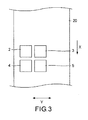
- FIG. 3 is a drawing of the inkjet printing device according to the embodiment of the invention.
- the same structural elements as those described in the first embodiment are illustrated with the same reference numerals and not described again.
- the device has four inkjet heads. Two of the four inkjet heads are aligned in the direction intersecting the direction of transfer (direction indicated by arrow Y in the drawing), while the other two inkjet heads are respectively located on the upstream side in the direction of transfer relative to the two inkjet heads aligned in the intersecting direction.
- the yellow and black inks are discharged through two inkjet heads 4 and 5 on the downstream side in the direction of transfer of the medium 20.
- the serial head inkjet printing device can be compactly structured as compared to disposing all of the inkjet heads along the direction of transfer.
- the inkjet printing device 100 includes: the transferring roller for transferring the medium 20; the inkjet heads that respectively discharge inks on the medium 20 to carry out a print job; the print-heater 6 for heating the medium 20, the print-heater 6 being disposed so as to face the region where the inks are discharged through the inkjet heads with the medium 20 interposed therebetween; and the after-heater 6 for heating the inks discharged on the medium 20, the after-heater 6 being installed on the downstream side in the direction of transfer of the medium 20 relative to the print-heater 6, wherein the plural inkjet heads respectively discharge the inks in different colors and are aligned in the direction of transfer.
- the inkjet heads 2 to 5 that discharge the different color inks are aligned in the direction of transfer.
- the inkjet heads 2 to 5 thus aligned in the direction of transfer discharge the respective inks in a sequential order on the medium 20 while being transferred.
- one of the inkjet heads is discharging its ink on the medium 20
- the ink discharged and adhered thereto is heated by the print-heater 6.
- the ink previously discharged and adhered to the medium 20 has already been thickened to a given or higher degree of viscosity. This ink, therefore, has no chance of smearing.
- the inks on the medium 20 can provide a high-quality print.
- the inkjet printing device 100 is further characterized in that, of the plurality of inkjet heads 2 to 5, the inkjet heads that discharge the inks in any colors but black are arranged from the upstream side toward the downstream side in the direction of transfer, so that the inks in different colors are discharged through the heads in the order of lower clarity.
- the plural inkjet heads discharge the inks in any colors but black in the order of lower clarity from the upstream side toward the downstream side in the direction of transfer of the print medium. Therefore, the inks of higher clarity are discharged on the inks of lower clarity. This prevents that incident light is reflected or absorbed by an ink surface alone, allowing the inks to exhibit their colors more vividly.
- the inkjet printing device 100 is further characterized in that the plurality of inkjet heads 2 to 5 is at least four inkjet heads that are aligned along the direction of transfer, and the four inkjet heads 2 to 5 are arranged from the upstream side toward the downstream side in the direction of transfer so as to respectively discharge cyan, magenta, yellow, and black inks in a sequential order.
- the inkjet printing device 100 thus characterized discharges the different color inks except the black ink in the order of lower clarity. This allows the inks to exhibit their colors more vividly.
- the plural inkjet heads 2 to 5 may be spaced at intervals optionally decided depending on such factors as transfer speed of the print medium, types of used inks, type of the print medium, heating temperatures, and environmental temperature.
- the inkjet printing device 100 is further characterized in that the plurality of inkjet heads 2 to 5, facing the medium 20, moves in the direction intersecting the direction of transfer, the inkjet heads are at least four inkjet heads, two of the four inkjet heads are aligned in the direction intersecting the direction of transfer, the other two inkjet heads are located on the upstream side in the direction of transfer relative to the two inkjet heads aligned in the intersecting direction, and the two inkjet heads on the downstream side in the direction of transfer respectively discharge the yellow and black inks.
- the serial head inkjet printing device 100 can be compactly structured as compared to disposing plurality of the inkjet heads 2 to 5 along the direction of transfer.
- the inkjet printing method includes: the transfer step of transferring the medium 20; the print step of discharging the inks on the medium 20 through the inkjet heads to carry out a print job; the first heating step of heating the medium 20 facing the region where the inks are discharged through the inkjet heads; and the second heating step of heating the inks discharged on the medium 20 transferred subsequent to the first heating step, wherein the plural inkjet heads 2 to 5 respectively discharge the inks in different colors and are aligned in the direction of transfer of the medium 20.
- This inkjet printing method provides similar technical advantages to those provided by the inkjet printing device 100.
- the invention is advantageously applicable to inkjet printing.
Landscapes
- Health & Medical Sciences (AREA)
- General Health & Medical Sciences (AREA)
- Toxicology (AREA)
- Ink Jet (AREA)
Abstract
Description
- The present invention relates to an inkjet printing device and an inkjet printing method.
-
Patent Document 1 describes a printer equipped with a pre-heater for preheating an unprinted medium, and a print-heater for heating the medium with an object just printed thereon. - Patent Document 1: Japanese Patent Application Laid-Open No.
2010-30313 A - The serial inkjet printer described in
Patent Document 1 has an unsolved problem; smearing of ink discharged on the medium through an inkjet head may degrade the quality of a printed image. - The invention has been accomplished to solve this problem, and has an object to provide an inkjet printing device and an inkjet printing method by which high-quality printing is fulfilled.
- To achieve the object, an inkjet printing device according to the invention includes: a transferring unit for transferring a print medium; an inkjet head for discharging an ink on the print medium to carry out a print job; a print-heater for heating the print medium, the print-heater being disposed so as to face a region where the ink is discharged through the inkjet head with the print medium interposed therebetween; and an after-heater for heating the ink discharged on the print medium, the after-heater being installed on a downstream side in a direction of transfer of the print medium relative to the print-heater, wherein the inkjet printing device includes a plurality of inkjet heads as the inkjet head, and the plurality of inkjet heads discharges the inks in different colors and is aligned in the direction of transfer.
- The plural inkjet heads that respectively discharge the inks in different colors are aligned in the direction of transfer. These inkjet heads thus aligned in the direction of transfer discharge the respective inks in a sequential order on the print medium while being transferred. While one of the inkjet heads is discharging its ink on the print medium, the ink discharged and adhered to the print medium is heated by the print-heater. When another one of the inkjet heads starts to discharge its ink on the print medium, the ink previously discharged and adhered to the print medium has already been thickened to a given or higher degree of viscosity. This ink, therefore, has no chance of smearing. When the ink is discharged on the print medium through another one of the inkjet heads, therefore, bleeding between colors of the inks does not occur. Besides, heating the print medium by the print-heater serves to thicken the ink discharged later to a given or higher degree of viscosity before smearing of the ink starts. Thus, smearing of the inks discharged on the print medium is effectively prevented.
- By preventing smearing of the discharged inks on the print medium, the inks on the print medium can provide a high-quality print.
- Preferably, the inkjet printing device according to the invention is further characterized in that, of the plurality of inkjet heads, the inkjet heads that discharge the inks in any colors but black are arranged from an upstream side toward the downstream side in the direction of transfer, so that the inks in different colors are discharged through the inkjet heads in the order of lower clarity.
- The plural inkjet heads discharge the inks in any colors but black in the order of lower clarity from the upstream side toward the downstream side in the direction of transfer of the print medium. Therefore, the ink of higher clarity is discharged on the ink of lower clarity. This prevents that incident light is reflected or absorbed by an ink surface alone, allowing the inks to exhibit their colors more vividly.
- Preferably, the inkjet printing device according to the invention is further characterized in that the plurality of inkjet heads is at least four inkjet heads that are aligned along the direction of transfer, and the four inkjet heads are arranged from the upstream side toward the downstream side in the direction of transfer so as to respectively discharge cyan, magenta, yellow, and black inks in a sequential order.
- The inkjet printing device thus characterized discharges the different color inks except the black ink in the order of lower clarity. This allows the inks to exhibit their colors more vividly. The plural inkjet heads may be spaced at intervals optionally decided depending on such factors as transfer speed of the print medium, types of used inks, type of the print medium, heating temperatures, and environmental temperature.
- Preferably, the inkjet printing device according to the invention is further characterized in that the plurality of inkjet heads, facing the print medium, moves in a direction intersecting the direction of transfer, the plurality of inkjet heads is at least four inkjet heads, two of the four inkjet heads are aligned in the direction intersecting the direction of transfer, other two of the four inkjet heads are located on the upstream side in the direction of transfer relative to the two of the four inkjet heads aligned in the direction intersecting the direction of transfer, and the two of the four inkjet heads on the downstream side in the direction of transfer respectively discharge the yellow and black inks.
- By disposing two of the inkjet heads in the direction intersecting the direction of transfer, the serial head inkjet printing device can be compactly structured as compared to disposing plurality of the inkjet heads along the direction of transfer.
- An inkjet printing method according to the invention includes: a transfer step of transferring a print medium; a print step of discharging an ink on a print medium through an inkjet head to carry out a print job; a first heating step of heating the print medium facing a region where the ink is discharged through the inkjet head; and a second heating step of heating the ink on the print medium transferred subsequent to the first heating step, wherein a plurality of inkjet heads is provided as the inkjet head, and the plurality of inkjet heads discharges the inks in different colors and is aligned in a direction of transfer of the print medium.
- The inkjet printing method according to the invention provides similar technical advantages to those provided by the inkjet printing device according to the invention.
- The inkjet printing device and the inkjet printing method according to the invention can both advantageously fulfill high-speed and high-quality printing.
-
-
FIG. 1 is a drawing of an inkjet printing device according to an embodiment of the invention. -
FIG. 2 is a drawing of an inkjet printing device according to a modified example of the embodiment. -
FIG. 3 is a drawing of an inkjet printing device according to another embodiment of the invention. - An embodiment of the invention is hereinafter described in detail referring to FIGFIG. 1.
FIG. 1 is a drawing of an inkjet printing device according to the embodiment. - An
inkjet printing device 100 according to the embodiment includes: a transferring roller (transferring unit, not illustrated) for transferring a medium (print medium) 20;inkjet heads 2 to 5 that respectively discharge inks on themedium 20 to carry out a print job; a print-heater 6 for heating themedium 20, the print-heater 6 being disposed so as to face a region where the inks are discharged through theinkjet heads 2 to 5 with themedium 20 interposed therebetween; and an after-heater 7 for heating the inks discharged on themedium 20, the after-heater 7 being installed on a downstream side in a direction of transfer of the medium 20 (direction indicated by arrow X inFIG. 1 ) relative to the print-heater 6. Theplural inkjet heads 2 to 5 respectively discharge the inks in different colors and are aligned in the direction of transfer. Theinkjet printing device 100 according to the embodiment further includes a take-up roll 1, afan 8,ultraviolet emitting lamps 10 to 12, and a warm/hot air heater 9. If smearing of the inks can be prevented by the print-heater 6 alone, theultraviolet emitting lamps - The
inkjet printing device 100 is configured to discharge inks on themedium 20 to obtain a print object inkjet-printed thereon. Examples of the inkjet printing device according to the invention are serial head inkjet printing device, and line head inkjet printing device. The printer of the former type has movable inkjet heads and discharges inks on a print medium through the heads moving in a direction intersecting a direction of transfer of the print medium. The printer of the latter type has relatively long and stationary inkjet heads and discharges inks through the heads on the print medium while being transferred. - The transferring roller for transferring the
medium 20 is installed on the downstream or upstream side in the direction of transfer in vicinity of a region where themedium 20 is printed. By driving the transferring roller, themedium 20 is transferred by a frictional force generated by the roller. - The take-
up roll 1 winds themedium 20 around its outer periphery to retrieve the printedmedium 20 in the form of a roll. The take-up roll 1 is located on the downstream side in the direction of transfer of themedium 20. By driving the take-up roll 1 in a manner that coordinates with the transferring roller, themedium 20 transferred by the transferring roller is prevented from slackening when wound around the take-up roll. - The
inkjet heads 2 to 5 discharge inks on themedium 20 to print an object thereon. Theinkjet heads 2 to 5 discharge inks in different colors and are aligned in the direction of transfer of themedium 20. - According to the embodiment, the
inkjet heads 2 to 5 are aligned along the direction of transfer of the medium 20 (direction indicated by arrow X inFIG. 1 ). Theinkjet heads 2 to 5 are arranged from the upstream side toward the downstream side in the direction of transfer so as to respectively discharge cyan, magenta, yellow, and black inks in a sequential order. Specifically, theinkjet head 2 discharges the cyan ink, theinkjet head 3 discharges the magenta ink, theinkjet head 4 discharges the yellow ink, and theinkjet head 5 discharges the black ink. - According to the embodiment, of the plural inkjet heads, the
inkjet heads 2 to 4 that discharge the color inks other than the black ink are preferably arranged from the upstream side toward the downstream side in the direction of transfer of themedium 20, so that the different color inks are discharged through these heads in the order of lower clarity. The inkjet printing device thus characterized discharges the different color inks except the black ink in the order of lower clarity, so that the inks of higher clarity are discharged on the inks of lower clarity. This prevents that incident light is reflected or absorbed by an ink surface alone, allowing the inks to exhibit their colors more vividly. The plural inkjet heads may be spaced at intervals optionally decided depending on such factors as transfer speed of the print medium, types of used inks, and type of the print medium, heating temperatures, and environmental temperature. For example, the inkjet heads may be spaced from one another by a distance that the slowest-drying ink among all the inks heated by the print-heater 6 described later can be dry enough not to smear, or the inter-head intervals may be variable depending on the properties of the discharged inks. - The inkjet head that discharges the black ink may be located on the upstream side or the downstream side relative to the other ink discharging jet heads.
- Although the embodiment provides four inkjet heads, the inkjet printing device according to the invention has any number more than one of inkjet heads that respectively discharge different color inks. Optionally, the device may have a plurality of inkjet heads that discharge inks of the same color.
- Examples of colors of the inks used in the inkjet heads according to the invention include, but are not limited to, regular colors such as cyan, magenta, yellow, and black, lightened colors of these regular colors, specific colors such as orange, green, white, metallic, and clear colors, and combinations of these colors.
- The print-
heater 6 is installed so as to face the region where the inks are discharged through the inkjet heads 2 to 5 with the medium 20 interposed therebetween. The print-heater 6, by heating the medium 20, heats the inks discharged on the medium 20. - The print-
heater 6 heats the inks on the medium 20 preferably at temperatures equal to or higher than 30°C and equal to or lower than 90°C, and more preferably at temperatures equal to or higher than 40°C and equal to or lower than 70°C. Heating the ink at temperatures equal to or higher than 40°C allows a solvent contained in the ink to evaporate, increasing the viscosity of the ink in a short period of time, while heating the ink at temperatures equal to or lower than 70°C can better control the occurrence of cockling with print media inferior in heat resistance, a material of which is, for example, vinyl chloride. - A pre-heater for heating the medium 20 may be further installed on the upstream side in the direction of transfer of the medium 20 relative to the print-
heater 6. Preheating the medium 20 by the pre-heater can efficiently evaporate the solvent contained in the ink discharged on the medium 20. If using, as the medium 20, a print medium inferior in heat resistance, the print-heater 6 at high temperatures is likely to provoke the occurrence of cockling. However, preheating the medium 20 by the pre-heater makes high-temperature heating by the print-heater 6 unnecessary, effectively avoiding the occurrence of cockling. - The ink used in the inkjet printing device according to the invention contains a solvent and is curable by radiation irradiated thereon. For example, the ink contains at least one of curable monomers and curable oligomers that are polymerized by radiation irradiated thereon.
- The ink is heated to volatilize the solvent and thereby increased in viscosity. Then, radiation is irradiated on the ink to polymerize at least one of curable monomers and curable oligomers. As used herein, "radiation" is a collective term for various kinds of particle beams and electromagnetic waves. An example of the particle beams is electron beam, while an example of the electromagnetic waves is ultraviolet. An example of inks of ultraviolet curing type is a solvent UV ink.
- As used herein, "curable monomer" is a monomer that is polymerized under some kind of externally applied stimulus to form a cured resin, and "curable oligomer" is an oligomer that is polymerized under some kind of externally applied stimulus to form a cured resin. Examples of the curable monomer are monomers or oligomers of ultraviolet curing type which are cured by ultraviolet irradiated thereon (hereinafter, "ultraviolet" may be referred to as "UV"). Examples of the curable oligomers are monomers or oligomers of electron beam curing type which are cured by electron beam irradiated thereon. The curable monomers or curable oligomers polymerized and cured are increased in viscosity. Among the examples of radiation, the
inkjet printing device 100 according to the embodiment irradiates ultraviolet emitted from theultraviolet emitting lamps 10 to 12 described later. This is, however, a non-limiting example. - The ink used in the inkjet printing device according to the invention contains a solvent. The solvent-containing ink, when heated and evaporated, is increased in viscosity. Such a solvent-diluted ink is advantageous in that when UV is irradiated on the ink during the heating, its degree of cure is not as high as the other known UV inks. Thus, the degree of cure of the ink through the radiation, such as ultraviolet, is easily adjustable.
- Examples of the solvent are glycol ethers and glycol ether acetates, including propylene glycol monomethyl ether, ethylene glycol monomethyl ether acetate, ethylene glycol monoethyl ether acetate, ethylene glycol monobutyl ether acetate, diethylene glycol monomethyl ether acetate, diethylene glycol monoethyl ether acetate, diethylene glycol monobutyl ether acetate, propylene glycol monomethyl ether acetate, dipropylene glycol monomethyl ether acetate, ethylene glycol monomethyl ether propionate, ethylene glycol monoethyl ether propionate, ethylene glycol monobutyl ether propionate, diethylene glycol monomethyl ether propionate, diethylene glycol monoethyl ether propionate, diethylene glycol monobutyl ether propionate, propylene glycol monomethyl ether propionate, dipropylene glycol monomethyl ether propionate, ethylene glycol monomethyl ether butyrate, ethylene glycol monoethyl ether butyrate, ethylene glycol monobutyl ether butyrate, diethylene glycol monomethyl ether butyrate, diethylene glycol monoethyl ether butyrate, diethylene glycol monobutyl ether butyrate, propylene glycol monomethyl ether butyrate, and dipropylene glycol monomethyl ether butyrate.
- Other than the before-mentioned examples, the solvent may be a hydrocarbon-based solvent. Examples of the hydrocarbon-based solvent are n-hexane, n-heptane, n-octane, isooctane, cyclohexane, methylcyclohexane, benzene, toluene, o-xylene, m-xylene, p-xylene, and ethylbenzene.
- Other than the before-mentioned examples, the solvent may be an ester-based solvent. Examples of the ester-based solvents are propyl formate, n-butyl formate, isobutyl formate, amyl formate, ethyl acetate, n-propyl acetate, isopropyl acetate, n-butyl acetate, isobutyl acetate, secondary butyl acetate, n-amyl acetate, isoamyl acetate, methyl isoamyl acetate, secondary hexyl acetate, methyl propionate, ethyl propionate, n-butyl propionate, methyl butyrate, ethyl butyrate, methyl lactate, and γ-butyrolactone.
- Other than the before-mentioned examples, the solvent may be a ketone-based solvent. Examples of the ketone-based solvents are methyl ethyl ketone, methyl-n-propyl ketone, methyl-n-butyl ketone, methyl isobutyl ketone, diethyl ketone, ethyl-n-butyl ketone, di-n-propyl ketone, and mesityl oxide.
- The solvent contained in the ink for the inkjet printing device according to the invention is preferably at least one selected from the groups of exemplified solvents. Such a solvent can be efficiently evaporated by heating.
- The solvent content for the whole quantity of the ink (solvent UV ink) may be optionally decided depending on intended uses. For example, the solvent content is preferably equal to or greater than 10 wt.%, and more preferably equal to or less than 55 wt.%. The solvent contained by a weight percentage within this range can be efficiently evaporated by heating.
- The
fan 8 blows air in the direction of transfer of the medium 20 to prevent that gas generated by evaporating the ink condenses, forming dew drops. As required, thefan 8 may be configured to blow hot air. - Each of the inkjet heads 2 to 5 has one of the
ultraviolet emitting lamps 10. Theultraviolet emitting lamps 10 respectively irradiate ultraviolet on the inks discharged on the medium 20 through the inkjet heads 2 to 5, thereby curing the inks. If the heating by the print-heater 6 is sufficient for preventing smearing of the inks, the inkjet heads may need not be equipped with theultraviolet emitting lamps 10. - The ink for the inkjet printing device according to the invention is curable by radiation irradiated thereon. The inks on the medium 20 can be cured by irradiating thereon ultraviolet emitted from the
ultraviolet emitting lamps 10. - The
ultraviolet emitting lamp 10 may be one selected from UV-LED lamps, metal-halide lamps, black light lamps, germicidal lamps, xenon lamps, and combinations of these lamps. A range of ultraviolet wavelengths when using a UV-LED lamp is, for example, 350 nm to 420 nm. An amount of ultraviolet irradiation is preferably decided within such a range of values that allows curing of the inks on the medium 20 to a smearing-preventable extent (semi-cured). - Through ultraviolet irradiation by the
ultraviolet emitting lamps 10, the inks are preferably cured until their degrees of viscosity are equal to or greater than 200 mPa·sec. and equal to or less than 5,000 mPa·sec. The ink viscosity equal to or greater than 200 mPa·sec. provides the following advantages; smearing of the inks is prevented, and ink droplets on the medium 20 are spread enough to flatten the surface of a print. The ink viscosity equal to or less than 5,000 mPa·sec. can more effectively prevent smearing of the inks. - According to the embodiment, the different color inks discharged through the inkjet heads 2 to 5 can be cured, one each at a time, by the
ultraviolet emitting lamps 10 installed in these inkjet heads. For example, the cyan ink discharged through theinkjet head 2 is cured by theultraviolet emitting lamp 10 installed in thehead 2. Then, the magenta ink discharged through theinkjet head 3 is cured by theultraviolet emitting lamp 10 installed in thehead 3. By thus curing each color ink at a time, the inks discharged on the medium 20 are very lustrous and improved in smoothness. - An
ultraviolet emitting lamp 11 is installed adjacent to theinkjet head 5 in the direction indicated by arrow X. This ultraviolet emitting lamp is intended to irradiate ultraviolet on the inks on the medium 20 already ultraviolet-irradiated by theultraviolet emitting lamps 10, thereby further curing the inks. If the heating by the print-heater 6 is sufficient for preventing smearing of the inks, theultraviolet emitting lamp 11 may be unnecessary. - After ultraviolet is irradiated by the
ultraviolet emitting lamps 10 on the inks on the medium 20, the transferring roller is driven to transfer the medium 20 in the direction indicated by arrow X. After ultraviolet is irradiated on the inks on the medium 20 by theultraviolet emitting lamps 10, ultraviolet emitted from theultraviolet emitting lamp 11 is then irradiated on the inks on the medium 20 to further cure the inks. - The
ultraviolet emitting lamp 11 may be one selected from UV-LED lamps, metal-halide lamps, black light lamps, germicidal lamps, xenon lamps, and combinations of these lamps. A range of ultraviolet wavelengths when using a UV-LED lamp is, for example, 350 nm to 420 nm. An amount of ultraviolet irradiation is preferably decided within such a range of values that allows curing of the inks on the medium 20 to a smearing-preventable extent (semi-cured). - Through ultraviolet irradiation by the
ultraviolet emitting lamp 11, the inks are preferably cured until their degrees of viscosity are equal to or greater than 200 mPa·sec. and equal to or less than 5,000 mPa·sec. The ink viscosity equal to or greater than 200 mPa·sec. provides the following advantages; smearing of the inks is prevented, and ink droplets on the medium 20 are spread enough to flatten the surface of a print. The ink viscosity equal to or less than 5,000 mPa·sec. can more effectively prevent smearing of the inks. - The warm/
hot air heater 9 for heating the inks on the medium 20 is located on the downstream side in the direction of transfer of the medium 20 relative to theultraviolet emitting lamp 11. The warm/hot air heater 9 blasts hot air onto the inks on the medium 20 to volatilize the solvents still left in the inks heated by the print-heater 6. - The after-
heater 7 for heating the inks on the medium 20 is located on the downstream side in the direction of transfer of the medium 20 relative to the print-heater 6. The after-heater 7 heats the inks on the medium 20 to volatilize the solvents still left in the inks heated by the print-heater 6. - An
ultraviolet emitting lamp 12 is installed adjacent to the warm/hot air heater 9 in the direction indicated by arrow X. This ultraviolet emitting lamp is intended to further cure the inks by irradiating ultraviolet on the solvent-volatilized inks heated by the after-heater 7 and the warm/hot air heater 9. - After the inks on the medium 20 are heated by the after-
heater 7 and the warm/hot air heater 9 and the solvents contained therein are thereby volatilized, the transferring roller is driven to transfer the medium 20 in the direction indicated by arrow X. Then, ultraviolet emitted from theultraviolet emitting lamp 12 is irradiated on the inks on the medium 20 to fully cure the inks. - The
ultraviolet emitting lamp 12 may be one selected from UV-LED lamps, metal-halide lamps, black light lamps, germicidal lamps, xenon lamps, and combinations of these lamps. A range of ultraviolet wavelengths when using a UV-LED lamp is, for example, 350 nm to 420 nm. An amount of ultraviolet irradiation is suitably decided within such a range of values that allows the inks on the medium 20 to be fully cured. - In the
inkjet printing device 100, the inkjet heads 2 to 5 that respectively discharge the inks in different colors are aligned in the direction of transfer. The inkjet heads 2 to 5 thus aligned in the direction of transfer discharge the respective inks in a sequential order on the medium 20 while being transferred. While one of the inkjet heads (for example, inkjet head 2) is discharging its ink on the medium 20, the ink discharged and adhered to the medium 20 is heated by the print-heater 6. When another one of the inkjet heads (for example, inkjet head 3) starts to discharge its ink on the medium 20, the ink previously discharged and adhered to the medium 20 has already been thickened to a given or higher degree of viscosity. This ink, therefore, has no chance of smearing. When the ink is discharged on the medium 20 through another one of the inkjet heads, therefore, bleeding between colors of the inks does not occur. Besides, heating the medium 20 by the print-heater 6 serves to thicken the ink discharged later to a given or higher degree of viscosity before smearing of the ink starts. Thus, smearing of the inks discharged on theprint medium 20 is effectively prevented. - When the black ink, which becomes particularly noticeable if smeared, is discharged through the
inkjet head 5 on the downstream side in the direction of transfer, any other color inks on the medium 20 have already been increased in viscosity to a smearing-preventable extent. Therefore, there is no risk of bleeding between black and other colors of the inks, leading to improvements in a print quality. - Thus, possible bleeding between colors of the inks on the medium 20 is well-controlled, and a printing speed can be accordingly improved even with inks slow to dry.
- By effectively preventing smearing of the inks discharged on the medium 20, the inks on the medium 20 can provide a high-quality print.
- An inkjet printing method using the
inkjet printing device 100 is hereinafter described. The inkjet printing method according to the embodiment includes: a transfer step of transferring the medium 20; a print step of discharging an ink on the medium 20 through an inkjet head to carry out a print job; a first heating step of heating the medium 20 facing a region where the ink is discharged through the inkjet head; and a second heating step of heating the ink discharged on the medium 20 transferred subsequent to the first heating step, wherein a plurality of inkjet heads is provided as the inkjet head, and the plurality of inkjet heads discharges the inks in different colors and is aligned in a direction of transfer of the medium 20. - The transferring roller of the
inkjet printing device 100 is driven to transfer the medium 20 in a direction indicated by arrow X (transfer step). - The inkjet heads 2 to 5 discharge inks on the medium 20 to print an object thereon (print step). The inkjet heads 2 to 5 respectively discharge the inks in different colors and are aligned in the direction of transfer of the medium 20, so that the different color inks can be discharged, on each at a time, on the medium 20.
- The print-
heater 6 heats the medium 20 facing the region where the inks are discharged through the inkjet heads 2 to 5 (first heating step). To prevent smearing of the inks discharged on the medium 20, preferably, the first heating step is performed concurrently with the print step, or the first heating step starts to be performed before the print step starts and continues until the print step is over. By irradiating ultraviolet on the inks on the medium 20 from theultraviolet emitting lamps 10 respectively installed in the inkjet heads 2 to 5, the different color inks are semi-cured, one each at a time, to a smearing-preventable extent. As far as the inks can be thickened by the first heating step to a degree of viscosity high enough not to smear, further cure of the inks by theultraviolet emitting lamps 10 may be unnecessary. - Subsequent to the first heating step, the
ultraviolet emitting lamp 11 irradiates ultraviolet on the inks on the transferred medium 20 to further cure the inks. As far as the inks can be thickened by the first heating step to a degree of viscosity high enough not to smear, further cure of the inks by theultraviolet emitting lamp 11 may be unnecessary. - Subsequent to the ultraviolet irradiation by the
ultraviolet emitting lamp 11, the inks on the transferredmedium 20 are heated by the after-heater 7 and the warm/hot air heater 9 (second heating step). The second heating step is performed to fully evaporate the solvents contained in the inks on the medium 20. Then, ultraviolet emitted from theultraviolet emitting lamp 12 is irradiated on the inks on the medium 20, and the inks on the medium 20 are thereby fully cured. - The inkjet printing method according to the embodiment can effectively control smearing of the inks on the print medium, thereby providing a high-quality print.
- A modified example of the embodiment is described below referring to
FIG. 2. FIG. 2 is a drawing of an inkjet printing device according to the modified example of the invention. Aninkjet printing device 200 according to the modified example is not equipped with theultraviolet emitting lamps 10 to 12 but with a coolingfan 13, which is a difference to theinkjet printing device 100 according to the embodiment described earlier. - Instead of the ink containing a solvent and cured by radiation irradiated thereon (solvent UV ink), the
inkjet printing device 200 according to the modified example uses a solvent ink, an aqueous ink, or a latex ink. - The ink used in the
inkjet printing device 200 according to the modified example may be a solvent ink containing any solvent but water or an aqueous ink containing water. The solvent contained in the solvent ink may be the same solvent as contained in the solvent UV ink. - The ink for the
inkjet printing device 200 according to the modified example may be a latex ink containing water or an organic solvent and a resin in which the resin is emulsified or suspended in the organic solvent or water. - An aqueous latex ink in which a resin is emulsified or suspended in water may as well be said to contain an aqueous emulsion or an aqueous suspension formed by the resin.
- Examples of the resin are water-soluble vinyl-based resins, acrylic resins, alkyd-based resins, polyester-based resins, polyurethane-based resins, silicon-based resins, fluororesins, epoxy-based resins, phenoxy-based resins, polyolefin-based resins, and modified resins obtained from these resins. Of these examples, acrylic resins, water-soluble polyurethane-based resins, water-soluble polyester-based resins, and water-soluble acrylic resins are preferably used, and acrylic resins are particularly preferable. The resin contained in the aqueous latex ink may be a resin solely used, or two or more different resins may be combined and used. The resin content in the aqueous latex ink may be optionally decided depending on the type of the used resin. For example, the resin content is preferably equal to or greater than 1 wt.%, and more preferably equal to or greater than 2 wt.% for the whole quantity of the aqueous latex ink. Also, the resin content is preferably equal to or less than 20 mass%, and more preferably equal to or less than 10 mass% for the whole quantity.
- The latex ink is curably by drying or heating. The latex ink is advantageously unlikely to merge into images printed with inks of any other types. Such an advantage makes the latex ink useful as a protective ink. Therefore, the
inkjet printing device 200 using the latex ink is advantageous in that more time is available for smoothing, providing a print with a better smoothed surface. Another advantage of the latex ink is its applicability to various kinds of print media. - The latex ink may further contain an emulsifier for emulsifying or suspending the resin.
- The organic solvent or water of the latex ink may additionally contain another resin dissolved therein in addition to the emulsified or suspended resin. This additional resin may be dissolved in the organic solvent or water to adjust the viscosity of the ink. After the ink is dehydrated by drying, particles of the emulsified or suspended resin are bonded to form a film. At the time, the additional resin may serve as a binding material that further strengthens the bond between the particles of the emulsified or suspended resin.
- The cooling
fan 13 blasts air onto the medium 20 heated by the afterheating unit 7 and the warm/hot air heater 9 to cool the medium 20 and the inks on the medium 20. - In any of the solvent ink, aqueous ink, or latex ink used in the
inkjet printing device 200, the solvent contained therein can be evaporated well to prevent smearing of the ink. In the case of reciprocating the inkjet heads to obtain a print, these heads discharge the inks in the same sequential order, meaning that the order of printed colors remains unchanged. The device thus advantageous excels in constant color reproducibility. - An inkjet printing device according to another embodiment of the invention is hereinafter described.
FIG. 3 is a drawing of the inkjet printing device according to the embodiment of the invention. The same structural elements as those described in the first embodiment are illustrated with the same reference numerals and not described again. - In the inkjet printing device according to the embodiment, the inkjet heads 2 to 5, facing the medium 20, move in a direction intersecting the direction of transfer. As illustrated in
FIG. 3 , the device has four inkjet heads. Two of the four inkjet heads are aligned in the direction intersecting the direction of transfer (direction indicated by arrow Y in the drawing), while the other two inkjet heads are respectively located on the upstream side in the direction of transfer relative to the two inkjet heads aligned in the intersecting direction. - The yellow and black inks are discharged through two
inkjet heads - By disposing two of the inkjet heads in the direction intersecting the direction of transfer, the serial head inkjet printing device can be compactly structured as compared to disposing all of the inkjet heads along the direction of transfer.
- The invention is not necessarily limited to the embodiment described so far and may be carried out in many other forms. The technical scope of the invention encompasses any modifications within the scope of the invention defined by the appended claims and embodiments obtained by variously combining the technical means disclosed herein.
- As described thus far, the
inkjet printing device 100 includes: the transferring roller for transferring the medium 20; the inkjet heads that respectively discharge inks on the medium 20 to carry out a print job; the print-heater 6 for heating the medium 20, the print-heater 6 being disposed so as to face the region where the inks are discharged through the inkjet heads with the medium 20 interposed therebetween; and the after-heater 6 for heating the inks discharged on the medium 20, the after-heater 6 being installed on the downstream side in the direction of transfer of the medium 20 relative to the print-heater 6, wherein the plural inkjet heads respectively discharge the inks in different colors and are aligned in the direction of transfer. - The inkjet heads 2 to 5 that discharge the different color inks are aligned in the direction of transfer. The inkjet heads 2 to 5 thus aligned in the direction of transfer discharge the respective inks in a sequential order on the medium 20 while being transferred. While one of the inkjet heads is discharging its ink on the medium 20, the ink discharged and adhered thereto is heated by the print-
heater 6. When another one of the inkjet heads starts to discharge its ink on the medium 20, the ink previously discharged and adhered to the medium 20 has already been thickened to a given or higher degree of viscosity. This ink, therefore, has no chance of smearing. When the ink is discharged on the medium 20 through another one of the inkjet heads, therefore, bleeding between colors of the inks does not occur. Besides, heating the medium 20 by the print-heater 6 serves to thicken the ink discharged later to a given or higher degree of viscosity before smearing of the ink starts. In this manner, smearing of the inks discharged on the medium 20 is effectively prevented. - By effectively preventing smearing of the inks discharged on the medium 20, the inks on the medium 20 can provide a high-quality print.
- The
inkjet printing device 100 is further characterized in that, of the plurality of inkjet heads 2 to 5, the inkjet heads that discharge the inks in any colors but black are arranged from the upstream side toward the downstream side in the direction of transfer, so that the inks in different colors are discharged through the heads in the order of lower clarity. - The plural inkjet heads discharge the inks in any colors but black in the order of lower clarity from the upstream side toward the downstream side in the direction of transfer of the print medium. Therefore, the inks of higher clarity are discharged on the inks of lower clarity. This prevents that incident light is reflected or absorbed by an ink surface alone, allowing the inks to exhibit their colors more vividly.
- The
inkjet printing device 100 is further characterized in that the plurality of inkjet heads 2 to 5 is at least four inkjet heads that are aligned along the direction of transfer, and the fourinkjet heads 2 to 5 are arranged from the upstream side toward the downstream side in the direction of transfer so as to respectively discharge cyan, magenta, yellow, and black inks in a sequential order. - The
inkjet printing device 100 thus characterized discharges the different color inks except the black ink in the order of lower clarity. This allows the inks to exhibit their colors more vividly. The plural inkjet heads 2 to 5 may be spaced at intervals optionally decided depending on such factors as transfer speed of the print medium, types of used inks, type of the print medium, heating temperatures, and environmental temperature. - The
inkjet printing device 100 is further characterized in that the plurality of inkjet heads 2 to 5, facing the medium 20, moves in the direction intersecting the direction of transfer, the inkjet heads are at least four inkjet heads, two of the four inkjet heads are aligned in the direction intersecting the direction of transfer, the other two inkjet heads are located on the upstream side in the direction of transfer relative to the two inkjet heads aligned in the intersecting direction, and the two inkjet heads on the downstream side in the direction of transfer respectively discharge the yellow and black inks. - By disposing two of the inkjet heads in the direction intersecting the direction of transfer, the serial head
inkjet printing device 100 can be compactly structured as compared to disposing plurality of the inkjet heads 2 to 5 along the direction of transfer. - The inkjet printing method includes: the transfer step of transferring the medium 20; the print step of discharging the inks on the medium 20 through the inkjet heads to carry out a print job; the first heating step of heating the medium 20 facing the region where the inks are discharged through the inkjet heads; and the second heating step of heating the inks discharged on the medium 20 transferred subsequent to the first heating step, wherein the plural inkjet heads 2 to 5 respectively discharge the inks in different colors and are aligned in the direction of transfer of the medium 20.
- This inkjet printing method provides similar technical advantages to those provided by the
inkjet printing device 100. - The invention is advantageously applicable to inkjet printing.
-
- 1: Take-up roll
- 2, 3, 4, 5: Inkjet head
- 6: Print-heater
- 7: After-heater
- 8: Fan
- 9: Warm/hot air heater
- 10: Ultraviolet emitting lamp
- 11: Ultraviolet emitting lamp
- 12: Ultraviolet emitting lamp
- 13: Cooling fan
- 20: Medium (print medium)
- 100: Inkjet printing device
Claims (5)
- An inkjet printing device, comprising:a transferring unit for transferring a print medium;an inkjet head for discharging an ink on the print medium to carry out a print job;a print-heater for heating the print medium, the print-heater being disposed so as to face a region where the ink is discharged through the inkjet head with the print medium interposed therebetween; andan after-heater for heating the ink discharged on the print medium, the after-heater being installed on a downstream side in a direction of transfer of the print medium relative to the print-heater, whereinthe inkjet printing device comprises a plurality of inkjet heads as the inkjet head, andthe plurality of inkjet heads discharges the inks in different colors and is aligned in the direction of transfer.
- The inkjet printing device according to claim 1, wherein
in the plurality of inkjet heads, the inkjet heads that discharge the inks in any colors but black are arranged from an upstream side toward the downstream side in the direction of transfer, so that the inks in different colors are discharged through the inkjet heads in the order of lower clarity. - The inkjet printing device according to claim 1 or 2, wherein
the plurality of inkjet heads is at least four inkjet heads that are aligned along the direction of transfer, and
the four inkjet heads are arranged from the upstream side toward the downstream side in the direction of transfer so as to respectively discharge cyan, magenta, yellow, and black inks in a sequential order. - The inkjet printing device according to claim 1 or 2, wherein
the plurality of inkjet heads, facing the print medium, moves in a direction intersecting the direction of transfer,
the plurality of inkjet heads is at least four inkjet heads,
two of the four inkjet heads are aligned in the direction intersecting the direction of transfer,
other two of the four inkjet heads are located on the upstream side in the direction of transfer relative to the two of the four inkjet heads aligned in the direction intersecting the direction of transfer, and
the two of the four inkjet heads on the downstream side in the direction of transfer respectively discharge yellow and black inks. - An inkjet printing method, comprising:a transfer step of transferring a print medium;a print step of discharging an ink on a print medium through an inkjet head to carry out a print job;a first heating step of heating the print medium facing a region where the ink is discharged through the inkjet head; anda second heating step of heating the ink on the print medium transferred subsequent to the first heating step, whereina plurality of inkjet heads is provided as the inkjet head, andthe plurality of inkjet heads discharges the inks in different colors and is aligned in a direction of transfer of the print medium.
Applications Claiming Priority (2)
| Application Number | Priority Date | Filing Date | Title |
|---|---|---|---|
| JP2012281642A JP2014124807A (en) | 2012-12-25 | 2012-12-25 | Ink jet printer and ink jet printing method |
| PCT/JP2013/083677 WO2014103782A1 (en) | 2012-12-25 | 2013-12-16 | Inkjet printing device and inkjet printing method |
Publications (2)
| Publication Number | Publication Date |
|---|---|
| EP2939833A1 true EP2939833A1 (en) | 2015-11-04 |
| EP2939833A4 EP2939833A4 (en) | 2017-03-15 |
Family
ID=51020870
Family Applications (1)
| Application Number | Title | Priority Date | Filing Date |
|---|---|---|---|
| EP13868469.1A Withdrawn EP2939833A4 (en) | 2012-12-25 | 2013-12-16 | Inkjet printing device and inkjet printing method |
Country Status (4)
| Country | Link |
|---|---|
| US (1) | US9718283B2 (en) |
| EP (1) | EP2939833A4 (en) |
| JP (1) | JP2014124807A (en) |
| WO (1) | WO2014103782A1 (en) |
Cited By (2)
| Publication number | Priority date | Publication date | Assignee | Title |
|---|---|---|---|---|
| EP3312013A1 (en) * | 2016-10-20 | 2018-04-25 | Mimaki Engineering Co., Ltd. | Printer and printing method |
| EP3363644A1 (en) * | 2017-02-21 | 2018-08-22 | Seiko Epson Corporation | Recording method and recording apparatus |
Families Citing this family (12)
| Publication number | Priority date | Publication date | Assignee | Title |
|---|---|---|---|---|
| JP6093472B1 (en) * | 2016-08-09 | 2017-03-08 | ローランドディー.ジー.株式会社 | Inkjet recording apparatus and printing method |
| JP6177413B1 (en) * | 2016-12-13 | 2017-08-09 | ローランドディー.ジー.株式会社 | Inkjet recording apparatus and printing method |
| JP6962001B2 (en) * | 2017-02-21 | 2021-11-05 | セイコーエプソン株式会社 | Recording method and recording device |
| CN108624119A (en) * | 2017-03-24 | 2018-10-09 | 卡西欧计算机株式会社 | The manufacturing method of ink, printing equipment, printing process and forming object |
| JP6835030B2 (en) | 2018-04-27 | 2021-02-24 | カシオ計算機株式会社 | Method for manufacturing a heat-expandable sheet, a method for manufacturing a heat-expandable sheet, and a method for manufacturing a modeled object |
| JP7259364B2 (en) * | 2019-01-31 | 2023-04-18 | セイコーエプソン株式会社 | Medium heating device and liquid ejection device |
| JP2021109391A (en) * | 2020-01-12 | 2021-08-02 | 株式会社ミマキエンジニアリング | Inkjet printing equipment |
| EP4159443B1 (en) * | 2020-06-30 | 2024-12-18 | Kyocera Corporation | Printing device |
| US11541673B2 (en) * | 2020-09-08 | 2023-01-03 | Xerox Corporation | System and method for removing ink solvent and water vapors in aqueous ink printers |
| US11884088B2 (en) * | 2021-05-26 | 2024-01-30 | Xerox Corporation | System and method for printing documents with texture |
| JP2023176509A (en) * | 2022-05-31 | 2023-12-13 | コニカミノルタ株式会社 | Cured film manufacturing method and cured film manufacturing device |
| JP2024027262A (en) * | 2022-08-17 | 2024-03-01 | セイコーエプソン株式会社 | Drying method, drying device, and printing device |
Family Cites Families (24)
| Publication number | Priority date | Publication date | Assignee | Title |
|---|---|---|---|---|
| EP0798119B1 (en) * | 1996-03-27 | 2002-12-04 | Canon Kabushiki Kaisha | Ink jet recording method and recording apparatus using same |
| JPH10278243A (en) * | 1997-04-04 | 1998-10-20 | Minolta Co Ltd | Ink-jet recording head |
| US6454402B1 (en) * | 1998-12-24 | 2002-09-24 | Canon Kabushiki Kaisha | Ink-jet printing method an ink-jet printing apparatus |
| US6390618B1 (en) * | 2000-01-07 | 2002-05-21 | Hewlett-Packard Company | Method and apparatus for ink-jet print zone drying |
| JP2002137375A (en) * | 2000-10-31 | 2002-05-14 | Riso Kagaku Corp | Ink jet printer and ink curing method for the printer |
| JP2004195996A (en) * | 2001-06-21 | 2004-07-15 | Ricoh Co Ltd | Ink jet recording device and copier |
| JP2003072059A (en) * | 2001-06-21 | 2003-03-12 | Ricoh Co Ltd | Ink jet recording device and copier |
| JP2004098577A (en) * | 2002-09-11 | 2004-04-02 | Ricoh Co Ltd | Liquid jet recording apparatus, ink jet head and ink |
| US6957886B2 (en) * | 2002-09-27 | 2005-10-25 | Eastman Kodak Company | Apparatus and method of inkjet printing on untreated hydrophobic media |
| US7216968B2 (en) * | 2003-05-24 | 2007-05-15 | Hewlett-Packard Development Company, L.P. | Media electrostatic hold down and conductive heating assembly |
| US7134749B2 (en) * | 2003-06-16 | 2006-11-14 | Kornit Digital Ltd. | Method for image printing on a dark textile piece |
| KR20070095465A (en) * | 2005-06-17 | 2007-10-01 | 삼성전자주식회사 | High quality printing method of inkjet image forming apparatus and inkjet image forming apparatus |
| JP2008024829A (en) * | 2006-07-21 | 2008-02-07 | Konica Minolta Holdings Inc | Inkjet recording method, inkjet ink and inkjet ink set |
| JP4971784B2 (en) * | 2006-12-27 | 2012-07-11 | 株式会社リコー | Ink media set, ink cartridge, ink jet recording method, ink jet recording apparatus, and ink recorded matter |
| JP5251479B2 (en) * | 2008-12-16 | 2013-07-31 | セイコーエプソン株式会社 | Recording device |
| JP2010208218A (en) * | 2009-03-11 | 2010-09-24 | Seiko Epson Corp | Printer |
| US8632157B2 (en) * | 2009-05-29 | 2014-01-21 | Konica Minolta Holdings, Inc. | Inkjet recording device |
| JP2011011442A (en) * | 2009-07-01 | 2011-01-20 | Seiko Epson Corp | Print method |
| JP4889059B2 (en) | 2009-11-09 | 2012-02-29 | 株式会社ミマキエンジニアリング | Inkjet printer |
| JP5556574B2 (en) * | 2010-10-19 | 2014-07-23 | セイコーエプソン株式会社 | Image recording apparatus and image recording method |
| JP2012171237A (en) * | 2011-02-22 | 2012-09-10 | Seiko Epson Corp | Image forming apparatus and image forming method |
| JP5717595B2 (en) * | 2011-03-29 | 2015-05-13 | 株式会社ミマキエンジニアリング | Curved surface printing method and printing system |
| JP5582175B2 (en) * | 2012-07-04 | 2014-09-03 | セイコーエプソン株式会社 | Recording device |
| JP6251475B2 (en) * | 2012-12-19 | 2017-12-20 | 株式会社ミマキエンジニアリング | Inkjet printer and printing method |
-
2012
- 2012-12-25 JP JP2012281642A patent/JP2014124807A/en active Pending
-
2013
- 2013-12-16 EP EP13868469.1A patent/EP2939833A4/en not_active Withdrawn
- 2013-12-16 WO PCT/JP2013/083677 patent/WO2014103782A1/en not_active Ceased
- 2013-12-16 US US14/655,054 patent/US9718283B2/en active Active
Non-Patent Citations (1)
| Title |
|---|
| See references of WO2014103782A1 * |
Cited By (4)
| Publication number | Priority date | Publication date | Assignee | Title |
|---|---|---|---|---|
| EP3312013A1 (en) * | 2016-10-20 | 2018-04-25 | Mimaki Engineering Co., Ltd. | Printer and printing method |
| EP3363644A1 (en) * | 2017-02-21 | 2018-08-22 | Seiko Epson Corporation | Recording method and recording apparatus |
| CN108454253A (en) * | 2017-02-21 | 2018-08-28 | 精工爱普生株式会社 | Recording method and recording device |
| US10265973B2 (en) | 2017-02-21 | 2019-04-23 | Seiko Epson Corporation | Recording method and recording apparatus |
Also Published As
| Publication number | Publication date |
|---|---|
| JP2014124807A (en) | 2014-07-07 |
| US9718283B2 (en) | 2017-08-01 |
| EP2939833A4 (en) | 2017-03-15 |
| WO2014103782A1 (en) | 2014-07-03 |
| US20150343796A1 (en) | 2015-12-03 |
Similar Documents
| Publication | Publication Date | Title |
|---|---|---|
| US9718283B2 (en) | Inkjet printing device and inkjet printing method | |
| CN103547458B (en) | Ink jet printing method | |
| US6561640B1 (en) | Systems and methods of printing with ultraviolet photosensitive resin-containing materials using light emitting devices | |
| US10792937B2 (en) | Printing apparatus and printing method | |
| JP6185758B2 (en) | Printing apparatus and printing method | |
| JP5843215B2 (en) | Inkjet recording method | |
| US10343416B2 (en) | Printer and printing method | |
| US9475277B2 (en) | Printing device | |
| WO2014098019A1 (en) | Inkjet printer and printing method | |
| WO2010140294A1 (en) | Ink, inkjet printer, and method for printing | |
| JP2006137185A (en) | Printing of radiation-curable ink into radiation-curable liquid layer | |
| US10926554B2 (en) | Printing apparatus and print method | |
| US10040298B2 (en) | Inkjet printing device, ink set, and inkjet printing method | |
| US10220639B2 (en) | Printer, printing method, and ink | |
| US10967652B2 (en) | Printing device and printing method | |
| US10696059B2 (en) | Printing apparatus and printing method | |
| WO2014136684A1 (en) | Inkjet printer, printing method, and ink | |
| WO2021177087A1 (en) | Printing device and printing method | |
| US10787004B2 (en) | Printing apparatus and print method | |
| JP2020062834A (en) | Printing device, printing method, powdering device and powdering method | |
| US10449784B2 (en) | Printing device and printing method | |
| EP1930169A1 (en) | Curing method for inkjet printing apparatus | |
| JP2021062530A (en) | Printing device and printing method |
Legal Events
| Date | Code | Title | Description |
|---|---|---|---|
| PUAI | Public reference made under article 153(3) epc to a published international application that has entered the european phase |
Free format text: ORIGINAL CODE: 0009012 |
|
| 17P | Request for examination filed |
Effective date: 20150727 |
|
| AK | Designated contracting states |
Kind code of ref document: A1 Designated state(s): AL AT BE BG CH CY CZ DE DK EE ES FI FR GB GR HR HU IE IS IT LI LT LU LV MC MK MT NL NO PL PT RO RS SE SI SK SM TR |
|
| AX | Request for extension of the european patent |
Extension state: BA ME |
|
| DAX | Request for extension of the european patent (deleted) | ||
| A4 | Supplementary search report drawn up and despatched |
Effective date: 20170215 |
|
| RIC1 | Information provided on ipc code assigned before grant |
Ipc: B41J 11/00 20060101ALI20170209BHEP Ipc: B41J 2/01 20060101AFI20170209BHEP |
|
| 17Q | First examination report despatched |
Effective date: 20171221 |
|
| STAA | Information on the status of an ep patent application or granted ep patent |
Free format text: STATUS: THE APPLICATION HAS BEEN WITHDRAWN |
|
| 18W | Application withdrawn |
Effective date: 20180405 |