EP2939755A1 - Deburring tool for laser beam machine and deburring method therefor - Google Patents
Deburring tool for laser beam machine and deburring method therefor Download PDFInfo
- Publication number
- EP2939755A1 EP2939755A1 EP13867052.6A EP13867052A EP2939755A1 EP 2939755 A1 EP2939755 A1 EP 2939755A1 EP 13867052 A EP13867052 A EP 13867052A EP 2939755 A1 EP2939755 A1 EP 2939755A1
- Authority
- EP
- European Patent Office
- Prior art keywords
- sheet material
- ball
- cut portion
- thermally cut
- deburring
- Prior art date
- Legal status (The legal status is an assumption and is not a legal conclusion. Google has not performed a legal analysis and makes no representation as to the accuracy of the status listed.)
- Withdrawn
Links
Images




Classifications
-
- B—PERFORMING OPERATIONS; TRANSPORTING
- B23—MACHINE TOOLS; METAL-WORKING NOT OTHERWISE PROVIDED FOR
- B23K—SOLDERING OR UNSOLDERING; WELDING; CLADDING OR PLATING BY SOLDERING OR WELDING; CUTTING BY APPLYING HEAT LOCALLY, e.g. FLAME CUTTING; WORKING BY LASER BEAM
- B23K26/00—Working by laser beam, e.g. welding, cutting or boring
- B23K26/0093—Working by laser beam, e.g. welding, cutting or boring combined with mechanical machining or metal-working covered by other subclasses than B23K
-
- B—PERFORMING OPERATIONS; TRANSPORTING
- B21—MECHANICAL METAL-WORKING WITHOUT ESSENTIALLY REMOVING MATERIAL; PUNCHING METAL
- B21D—WORKING OR PROCESSING OF SHEET METAL OR METAL TUBES, RODS OR PROFILES WITHOUT ESSENTIALLY REMOVING MATERIAL; PUNCHING METAL
- B21D19/00—Flanging or other edge treatment, e.g. of tubes
- B21D19/005—Edge deburring or smoothing
-
- B—PERFORMING OPERATIONS; TRANSPORTING
- B21—MECHANICAL METAL-WORKING WITHOUT ESSENTIALLY REMOVING MATERIAL; PUNCHING METAL
- B21J—FORGING; HAMMERING; PRESSING METAL; RIVETING; FORGE FURNACES
- B21J5/00—Methods for forging, hammering, or pressing; Special equipment or accessories therefor
- B21J5/02—Die forging; Trimming by making use of special dies ; Punching during forging
- B21J5/027—Trimming
-
- B—PERFORMING OPERATIONS; TRANSPORTING
- B21—MECHANICAL METAL-WORKING WITHOUT ESSENTIALLY REMOVING MATERIAL; PUNCHING METAL
- B21K—MAKING FORGED OR PRESSED METAL PRODUCTS, e.g. HORSE-SHOES, RIVETS, BOLTS OR WHEELS
- B21K23/00—Making other articles
-
- B—PERFORMING OPERATIONS; TRANSPORTING
- B23—MACHINE TOOLS; METAL-WORKING NOT OTHERWISE PROVIDED FOR
- B23K—SOLDERING OR UNSOLDERING; WELDING; CLADDING OR PLATING BY SOLDERING OR WELDING; CUTTING BY APPLYING HEAT LOCALLY, e.g. FLAME CUTTING; WORKING BY LASER BEAM
- B23K26/00—Working by laser beam, e.g. welding, cutting or boring
- B23K26/08—Devices involving relative movement between laser beam and workpiece
-
- B—PERFORMING OPERATIONS; TRANSPORTING
- B23—MACHINE TOOLS; METAL-WORKING NOT OTHERWISE PROVIDED FOR
- B23K—SOLDERING OR UNSOLDERING; WELDING; CLADDING OR PLATING BY SOLDERING OR WELDING; CUTTING BY APPLYING HEAT LOCALLY, e.g. FLAME CUTTING; WORKING BY LASER BEAM
- B23K26/00—Working by laser beam, e.g. welding, cutting or boring
- B23K26/08—Devices involving relative movement between laser beam and workpiece
- B23K26/083—Devices involving movement of the workpiece in at least one axial direction
-
- B—PERFORMING OPERATIONS; TRANSPORTING
- B23—MACHINE TOOLS; METAL-WORKING NOT OTHERWISE PROVIDED FOR
- B23K—SOLDERING OR UNSOLDERING; WELDING; CLADDING OR PLATING BY SOLDERING OR WELDING; CUTTING BY APPLYING HEAT LOCALLY, e.g. FLAME CUTTING; WORKING BY LASER BEAM
- B23K26/00—Working by laser beam, e.g. welding, cutting or boring
- B23K26/36—Removing material
- B23K26/38—Removing material by boring or cutting
-
- B—PERFORMING OPERATIONS; TRANSPORTING
- B23—MACHINE TOOLS; METAL-WORKING NOT OTHERWISE PROVIDED FOR
- B23K—SOLDERING OR UNSOLDERING; WELDING; CLADDING OR PLATING BY SOLDERING OR WELDING; CUTTING BY APPLYING HEAT LOCALLY, e.g. FLAME CUTTING; WORKING BY LASER BEAM
- B23K26/00—Working by laser beam, e.g. welding, cutting or boring
- B23K26/36—Removing material
- B23K26/40—Removing material taking account of the properties of the material involved
-
- B—PERFORMING OPERATIONS; TRANSPORTING
- B23—MACHINE TOOLS; METAL-WORKING NOT OTHERWISE PROVIDED FOR
- B23K—SOLDERING OR UNSOLDERING; WELDING; CLADDING OR PLATING BY SOLDERING OR WELDING; CUTTING BY APPLYING HEAT LOCALLY, e.g. FLAME CUTTING; WORKING BY LASER BEAM
- B23K26/00—Working by laser beam, e.g. welding, cutting or boring
- B23K26/60—Preliminary treatment
-
- B—PERFORMING OPERATIONS; TRANSPORTING
- B23—MACHINE TOOLS; METAL-WORKING NOT OTHERWISE PROVIDED FOR
- B23K—SOLDERING OR UNSOLDERING; WELDING; CLADDING OR PLATING BY SOLDERING OR WELDING; CUTTING BY APPLYING HEAT LOCALLY, e.g. FLAME CUTTING; WORKING BY LASER BEAM
- B23K26/00—Working by laser beam, e.g. welding, cutting or boring
- B23K26/70—Auxiliary operations or equipment
-
- B—PERFORMING OPERATIONS; TRANSPORTING
- B23—MACHINE TOOLS; METAL-WORKING NOT OTHERWISE PROVIDED FOR
- B23K—SOLDERING OR UNSOLDERING; WELDING; CLADDING OR PLATING BY SOLDERING OR WELDING; CUTTING BY APPLYING HEAT LOCALLY, e.g. FLAME CUTTING; WORKING BY LASER BEAM
- B23K26/00—Working by laser beam, e.g. welding, cutting or boring
- B23K26/70—Auxiliary operations or equipment
- B23K26/702—Auxiliary equipment
-
- B—PERFORMING OPERATIONS; TRANSPORTING
- B23—MACHINE TOOLS; METAL-WORKING NOT OTHERWISE PROVIDED FOR
- B23K—SOLDERING OR UNSOLDERING; WELDING; CLADDING OR PLATING BY SOLDERING OR WELDING; CUTTING BY APPLYING HEAT LOCALLY, e.g. FLAME CUTTING; WORKING BY LASER BEAM
- B23K37/00—Auxiliary devices or processes, not specially adapted for a procedure covered by only one of the other main groups of this subclass
- B23K37/02—Carriages for supporting the welding or cutting element
- B23K37/0211—Carriages for supporting the welding or cutting element travelling on a guide member, e.g. rail, track
- B23K37/0235—Carriages for supporting the welding or cutting element travelling on a guide member, e.g. rail, track the guide member forming part of a portal
-
- B—PERFORMING OPERATIONS; TRANSPORTING
- B23—MACHINE TOOLS; METAL-WORKING NOT OTHERWISE PROVIDED FOR
- B23K—SOLDERING OR UNSOLDERING; WELDING; CLADDING OR PLATING BY SOLDERING OR WELDING; CUTTING BY APPLYING HEAT LOCALLY, e.g. FLAME CUTTING; WORKING BY LASER BEAM
- B23K37/00—Auxiliary devices or processes, not specially adapted for a procedure covered by only one of the other main groups of this subclass
- B23K37/08—Auxiliary devices or processes, not specially adapted for a procedure covered by only one of the other main groups of this subclass for flash removal
-
- B—PERFORMING OPERATIONS; TRANSPORTING
- B24—GRINDING; POLISHING
- B24B—MACHINES, DEVICES, OR PROCESSES FOR GRINDING OR POLISHING; DRESSING OR CONDITIONING OF ABRADING SURFACES; FEEDING OF GRINDING, POLISHING, OR LAPPING AGENTS
- B24B39/00—Burnishing machines or devices, i.e. requiring pressure members for compacting the surface zone; Accessories therefor
-
- B—PERFORMING OPERATIONS; TRANSPORTING
- B24—GRINDING; POLISHING
- B24B—MACHINES, DEVICES, OR PROCESSES FOR GRINDING OR POLISHING; DRESSING OR CONDITIONING OF ABRADING SURFACES; FEEDING OF GRINDING, POLISHING, OR LAPPING AGENTS
- B24B9/00—Machines or devices designed for grinding edges or bevels on work or for removing burrs; Accessories therefor
-
- B—PERFORMING OPERATIONS; TRANSPORTING
- B21—MECHANICAL METAL-WORKING WITHOUT ESSENTIALLY REMOVING MATERIAL; PUNCHING METAL
- B21D—WORKING OR PROCESSING OF SHEET METAL OR METAL TUBES, RODS OR PROFILES WITHOUT ESSENTIALLY REMOVING MATERIAL; PUNCHING METAL
- B21D28/00—Shaping by press-cutting; Perforating
- B21D28/02—Punching blanks or articles with or without obtaining scrap; Notching
- B21D28/16—Shoulder or burr prevention, e.g. fine-blanking
-
- B—PERFORMING OPERATIONS; TRANSPORTING
- B23—MACHINE TOOLS; METAL-WORKING NOT OTHERWISE PROVIDED FOR
- B23K—SOLDERING OR UNSOLDERING; WELDING; CLADDING OR PLATING BY SOLDERING OR WELDING; CUTTING BY APPLYING HEAT LOCALLY, e.g. FLAME CUTTING; WORKING BY LASER BEAM
- B23K2101/00—Articles made by soldering, welding or cutting
- B23K2101/18—Sheet panels
-
- B—PERFORMING OPERATIONS; TRANSPORTING
- B23—MACHINE TOOLS; METAL-WORKING NOT OTHERWISE PROVIDED FOR
- B23K—SOLDERING OR UNSOLDERING; WELDING; CLADDING OR PLATING BY SOLDERING OR WELDING; CUTTING BY APPLYING HEAT LOCALLY, e.g. FLAME CUTTING; WORKING BY LASER BEAM
- B23K2101/00—Articles made by soldering, welding or cutting
- B23K2101/34—Coated articles ; Surface treated articles
-
- B—PERFORMING OPERATIONS; TRANSPORTING
- B23—MACHINE TOOLS; METAL-WORKING NOT OTHERWISE PROVIDED FOR
- B23K—SOLDERING OR UNSOLDERING; WELDING; CLADDING OR PLATING BY SOLDERING OR WELDING; CUTTING BY APPLYING HEAT LOCALLY, e.g. FLAME CUTTING; WORKING BY LASER BEAM
- B23K2101/00—Articles made by soldering, welding or cutting
- B23K2101/34—Coated articles ; Surface treated articles
- B23K2101/35—Surface treated articles
-
- B—PERFORMING OPERATIONS; TRANSPORTING
- B23—MACHINE TOOLS; METAL-WORKING NOT OTHERWISE PROVIDED FOR
- B23K—SOLDERING OR UNSOLDERING; WELDING; CLADDING OR PLATING BY SOLDERING OR WELDING; CUTTING BY APPLYING HEAT LOCALLY, e.g. FLAME CUTTING; WORKING BY LASER BEAM
- B23K2103/00—Materials to be soldered, welded or cut
- B23K2103/16—Composite materials
- B23K2103/166—Multilayered materials
Definitions
- the present invention relates to deburring tools that press surfaces of edge portions of thermally cut portions of sheet materials that have been thermally cut by laser processing machines to obtain smooth finish, and a deburring method therefor.
- slag or the like generated in the processing is solidified to generate a burr-like protrusion 70 in a surface edge portion, in particular, in a lower surface edge portion C along a thermally cut portion A of a sheet material W, as shown in Fig. 12 . Since molten metal is blown off from the upper side by inert gas during the thermal cutting process, the slag or the like tends to be accumulated on the lower side. Therefore, the protrusion 70 is generated in the lower surface edge portion C.
- a small projection 71 may be partially generated also in an upper surface edge portion B.
- the projection 71 is formed mainly by the metal Wb being molten during a thermal cutting process and the being blown off or scattered.
- the protrusion 70 and the projection 71 which are thus generated during the thermal cutting process are manually removed by using a sander in a later process.
- the protrusion 70 and the projection 71 are enlarged in exaggerated manners.
- Patent Document 1 For removing burr generated in a sheet material during a punching process with the use of a punch press, a deburring tool mounted on a tool supporter of the punch press has been known (for example, Patent Document 1).
- Patent Document 1 Japanese Patent No. 4916104
- An object of the present invention is to provide: a deburring tool capable of efficiently removing burr-like protrusions which are generated in a lower surface edge portion along a thermally cut portion of a sheet material in a thermal cutting process using a laser processing machine, with the use of a sheet material moving mechanism mounted on the laser processing machine; a laser processing machine including the deburring tool; and a deburring method for performing surface pressing process using the deburring tool.
- a deburring tool, of a laser processing machine, according to the present invention is used for a laser processing machine that includes: a laser head configured to irradiate a sheet material with a laser beam downward; and a sheet material moving mechanism configured to move, below the laser head, the sheet material in a front, rear, left, and right directions relative to the laser head, thereby to perform thermal cutting process for the sheet material by irradiating the sheet material, moved by the sheet material moving mechanism, with the laser beam.
- the deburring tool includes: upper and lower ball holding members disposed so as to oppose each other; and upper and lower balls rotatably supported by the respective upper and lower ball holding members, the upper and lower balls projecting so as to confront opposing surfaces of the respective lower and upper ball holding members.
- the sheet material In a state where a thermally cut portion of the sheet material is held between the upper ball and the lower ball, the sheet material is moved along the thermally cut portion by the sheet material moving mechanism, and a lower surface edge portion along the thermally cut portion of the sheet material is pressed upward by the lower ball.
- the thermally cut portion represents a slit-like portion or interspace obtained by a metal material being removed by thermal cutting process.
- portions, on both sides, separated by the thermally cut portion are, for example, a material portion and a product portion that are separated from each other, the thermally cut portion is not in a slit-like shape but is a virtual space between the end surface of the sheet material (product portion) and a virtual plane that is distant from the end surface by a width of the slit-like portion.
- the deburring tool having this configuration, by moving the sheet material while the sheet material is held between the upper and lower balls, a burr-like protrusion generated in the lower surface edge portion along the thermally cut portion of the sheet material is squashed and removed by the surface pressing or deburring press with the use of the lower ball.
- the "removed” described herein indicates that a portion, of the burr-like protrusion, protruding from the lower surface of the sheet material is at least reduced or eliminated by the squashing operation. Since the upper and lower balls are rotatably supported by the respective upper and lower ball holding members and freely rotate in any direction by the sheet material being moved, the sheet material can be smoothly moved. Accordingly, the surface pressing process for the removal of the burr-like protrusion can be sequentially performed with high efficiency.
- the sheet material in a state where the sheet material is held between the upper ball and the lower ball, the sheet material may be moved by the sheet material moving mechanism, and an upper surface edge portion along the thermally cut portion of the sheet material is pressed downward by the upper ball.
- the surface pressing process for removal can be sequentially performed with high efficiency for the projection generated in the upper surface edge portion, in addition to the burr-like protrusion generated in the lower surface edge portion along the thermally cut portion of the sheet material.
- the removal for the projection also indicates that a portion, of the projection, projecting from the upper surface of the sheet material is at least reduced or eliminated by the squashing operation.
- the laser processing machine includes the deburring tool described above. Therefore, the surface pressing process for removal can be sequentially performed with high efficiency for the burr-like protrusion generated in the lower surface edge portion along the thermally cut portion of the sheet material.
- a deburring method, for use in a thermally cut portion of a sheet material, according to the present invention performs, by using the deburring tool described above, dedurring press process for a thermally cut portion of a sheet material that is a plated steel sheet in which a surface of a steel is plated with a metal having a melting point lower than the steel.
- dedurring press process for a thermally cut portion of a sheet material that is a plated steel sheet in which a surface of a steel is plated with a metal having a melting point lower than the steel.
- a burr-like protrusion generated in the lower surface edge portion along the thermally cut portion of the sheet material is squashed and removed by the surface pressing using the lower ball.
- a projection generated in the upper surface edge portion is squashed and removed by the surface pressing using the upper ball.
- the projection can be removed by means of this deburring method. Since the upper and lower balls are rotatably supported by the respective upper and lower ball holding members and freely rotate in any direction by the sheet material being moved, the sheet material can be smoothly moved. Accordingly, the surface pressing process for the removal of the burr-like protrusion and the projection can be sequentially performed with high efficiency.
- Fig. 1 is a plan view of a schematic configuration of a laser processing machine including a deburring tool according to the preferred embodiment
- Fig. 2 is a side view thereof.
- the laser processing machine 1 is configured as a laser punch combination machine having a laser processing machine portion 2 and a punch press mechanism portion 3 combined with each other.
- a plate material or sheet material W is thermally cut at a laser processing position P1 by the laser processing machine portion 2, and the sheet material W is punched at a punching position P2 by the punch press mechanism portion 3.
- the laser processing position P1 and the punching position P2 are fixed positions.
- the sheet material W is moved by a sheet material moving mechanism 4 such that a portion, to be processed, of the sheet material W supported by a sheet material table 5 conforms with the laser processing position P1 or the punching process position P2.
- the laser processing machine portion 2 is disposed at the laser processing position P1 positioned at the front end of an upper frame portion 7a of a frame 7 having a C-shaped side surface, and includes: a laser head 11 configured to irradiate the sheet material W with a laser beam downward; a laser oscillator 12 disposed on a floor surface distant from the frame 7; and a transmission path 13 through which laser beam is guided from the laser oscillator 12 to the laser head 11.
- a transmission path 13 for example, an optical fiber for transmission is used.
- the punch press mechanism portion 3 includes disk-shaped upper and lower turrets 15 and 16 that serve as a tool supporter, and those upper and lower turrets 15 and 16 are supported by the upper frame portion 7a and a lower frame portion 7b of the frame 7, respectively, so as to be concentric with each other and rotatable about the vertical axis.
- a plurality of upper dies 17 and lower dies 18 for forming process, and an upper die 21 and a lower die 22 for deburring press or surface pressing are aligned in the circumferential direction.
- the upper die 21 and the lower die 22 for surface pressing may be provided at only one portion in the circumferential direction, or plural kinds of the upper and lower dies for surface pressing may be provided at a plurality of portions in the circumferential direction.
- a deburring tool 20 is formed by the paired upper die 21 and lower die 22 for surface pressing.
- the upper and lower turrets 15 and 16 are indexed by die indexing unit (not shown) mounted in the frame 7 such that desired dies are positioned to the punching position P2.
- die indexing unit (not shown) mounted in the frame 7 such that desired dies are positioned to the punching position P2.
- the upper die 17, 21 is driven by a ram 25 so as to ascend and descend.
- the ram 25 is supported by the upper frame portion 7a of the frame 7 so as to be ascendable and descendable via a guide member (not shown), and is driven by a punch driving mechanism 26 so as to ascend and descend.
- the punch driving mechanism 26 includes, for example, a servomotor 27 and a movement transforming mechanism 28 for transforming rotation of the motor into linear movement.
- the sheet material moving mechanism 4 includes a carriage 31 that moves in the front-rear direction (Y direction), a cross slide 32 that moves in the left-right direction (X direction) mounted on the carriage 31 and a workpiece holder 33 that is mounted on the cross slide 32 and holds the end portion of the sheet material W.
- a guide rail 34 is disposed below the carriage 31 so as to extend in the front-rear direction.
- the carriage 31 is moved along the guide rail 34 by a not-illustrated driving source for front-rear movement.
- the cross slide 32 is moved in the left-right direction relative to the carriage 31 by a not-illustrated driving source for left-right movement.
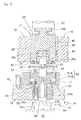
- Fig. 3 is a longitudinal cross-sectional view of the upper die 21 and the lower die 22 of the deburring tool 20 mounted to the respective upper and lower turrets 15 and 16.
- the upper die 21 and the lower die 22 are used for surface pressing process for edge portions B, C ( Fig. 12 ), on both the upper and lower surfaces along the thermally cut portion A, relative to the sheet material W having been thermally cut by the laser processing machine portion 2 ( Fig. 1, Fig. 2 ).
- the thermally cut portion A represents a slit-like portion or interspace obtained by a metal material being removed by thermal cutting process.
- a width a ( Fig. 12 ) of the thermally cut portion A is from about 0.2 mm to about 0.3 mm.
- the upper die 21 for surface pressing includes: a cylindrical upper die body 40 provided with a guide hole 40a that is opened on the lower side; a guide member 41 that is inserted into the guide hole 40a of the upper die body 40 so as to be ascendable and descendable; a ball holding member 42 fixed to the guide member 41; and a ball 43 that is rotatably supported by the ball holding member 42 and that projects downward.
- the guide member 41 is prevented from dropping, by a stopper 44 ( Fig. 3 ) disposed at the lower end of the upper die body 40, and is urged downward by a coil spring 45 inserted into the guide hole 40a.
- the ball 43 is pressed against the edge portion B ( Fig. 10 ) of the sheet material W, as described below, by force of the coil spring 45.
- the coil spring 45 may not necessarily be provided, and also, the ball 43 may be pressed against the edge portion B of the sheet material W by controlling driving of the ascending and descending of the ram 25 ( Fig. 2 ). Further, the ball 43 may be pressed against the edge portion B of the sheet material W by using both the coil spring 45 and the ram 25.
- the upper die 21 for surface pressing is fitted into a die holding hole 38 of the upper turret 15 so as to be ascendable and descendable, and a key 46 provided on an outer circumference of the upper die body 40 is engaged with a key groove 38a formed on an inner periphery of the die holding hole 38, to prevent the upper die 21 from rotating relative to the upper turret 15.
- the upper die 21 for surface pressing is connected, at the punching position P2 ( Fig. 1, Fig. 2 ), to the ram 25 via a T-shaped connecting portion 40b provided at the upper end of the upper die body 40.
- the lower die 22 for surface pressing includes: a lower die outer case 49 fixed to the lower turret 16 via a lower die holder 47; a lower die body 50 supported in the lower die outer case 49 so as to be ascendable and descendable; a ball holding member 52 fixed to an upper member 51A of the lower die body 50; and a ball 53 that is rotatably supported by the ball holding member 52 and that projects upward.
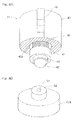
- Fig. 4B is a perspective view of the upper member 51A of the lower die body 50.
- the ball holding member 42 of the upper die 21 confronts the ball holding member 43 of the lower die 22, while a lower surface of the ball holding member 42 is oppose to a upper surface of the ball holding member 43. That is, the lower surface of the ball holding member 42 and the upper surface of the ball holding member 43 define opposed surfaces.
- the ball 43 of the upper die 21 is disposed in the opposed surface of the ball holding member 42 so as to project downwardly
- the ball 53 of the lower die 22 is disposed in the opposed surface of the ball holding member 52 so as to project upwardly, with the balls 43, 53 being opposed to each other.
- a diameter of each of the balls 43, 53 is sufficiently greater than the width a of the thermally cut portion A.
- the diameter of the ball 43 of the upper die 21 is about several times greater than the diameter of the ball 53 of the lower die 22. It is noted that the upper and the lower balls 43 and 53 may have the same diameter.
- the ball 43 and the ball holding member 42 of the upper die 21 are implemented as a free bearing, and the ball 43 is rotatably disposed in the ball holding member 42 that serves as a case, such that the ball 43 is prevented from dropping and partially projects from the ball holding member 42.
- the ball 53 and the ball holding member 52 of the lower die 22 are implemented as a free bearing as described for the upper die 21.
- the upper and lower free bearings may have the same structure except that the diameters of the balls 43 and 53 are different from each other. Alternatively, the structures of the balls 43 and 53 may be the same including the diameter thereof.
- the balls 43 and 53 are implemented as, for example, steel balls.
- the lower member 51B of the lower die body 50 is fitted into a guide hole 49a formed in the lower die outer case 49 so as to be ascendable and descendable.
- the lower die body 50 is supported so as to be ascendable and descendable relative to the lower die outer case 49.
- a bolt 55 that passes through a bolt insertion hole 54 formed in the lower die outer case 49 so as to be parallel to the guide hole 49a is screwed into the lower member 51B of the lower die body 50.
- the lower die body 50 is urged downward by a coil spring 56 disposed between a head portion 55a of the bolt 55 and a peripheral portion 54a of the bolt insertion hole 54.
- a lower die ascending and descending unit 57 is provided at a position below the lower turret 16 at the punching position P2.
- the lower die ascending and descending unit 57 causes the lower die 22 to ascend to a predetermined height, when the edge portions B, C on both the upper and lower surfaces along the thermally cut portion A of the sheet material W are surface-pressed or deburred by the deburring tool 20. As shown in a plan view of Fig. 5A and a front view of Fig.
- the lower die ascending and descending unit 57 includes: an advancing and retracting member 61 that is guided on a reaction force receiver 58 so as to advance and retract in, for example, a direction orthogonal to the radial direction of the lower turret 16 by a pair of guide members 59 and 60; and an actuator 62 that drives the advancing and retracting member 61.
- the upper surface of the advancing and retracting member 61 includes: an upper-side plane portion 61a and a lower-side plane portion 61c; and a tilted surface portion 61b that is tilted downward from the upper-side plane portion 61 a to the lower-side plane portion 61c.
- the actuator 62 is implemented as a fluid cylinder, and the front end of a piston rod of the actuator 62 is connected to the rear end of the advancing and retracting member 61 by means of a connecting member 63.
- a cam follower 64 disposed at the lower end of the lower member 51B of the lower die body 50 slidably contacts with the upper surface of the advancing and retracting member 61.
- the deburring tool 20 is used to perform surface pressing process along the thermally cut portion A.
- the surface pressing process may be performed for each thermally cut portion A, immediately after the thermal cutting process, prior to, for example, shift to the following thermally cutting portion A.
- the surface pressing process may be performed collectively for the thermally cut portions A when all the thermal cutting process has been completed.
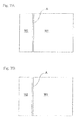
- the surface pressing process may be performed in a state where sheet material portions, such as a product sheet material W1 and an unprocessed sheet material W2 to be discarded, are positioned on both sides lateral to the thermally cut portion A, as shown in Fig. 7A .
- the surface pressing process may be also performed in a state where a sheet material portion, such as the product sheet material W1 separated from the unprocessed sheet material W2, is positioned on only one side lateral to the thermally cut portion A, as shown in Fig. 7B .
- the above surface pressing process is performed as follows. In the description herein, the surface pressing process in the case of the sheet material portions being positioned on both sides lateral to the thermally cut portion A, will be described.
- the upper and lower turrets 15 and 16 are driven to rotate, and the upper and lower dies 21 and 22 of the deburring tool 20 are indexed to the punching position P2.
- the sheet material W held by the workpiece holder 33 of the sheet material moving mechanism 4 is moved such that one end portion of the thermally cut portion A conforms with the punching position P2 as indicated by a solid line in Fig. 8 .
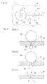
- step (A) of in Fig. 9 the upper die 21 is in the course of descending and the lower die 22 is in the course of ascending. At this time, the upper die 21 and the lower die 22 contact with the upper and lower surfaces, respectively, of the sheet material W.
- the upper die 21 has descended to the predetermined height
- the lower die 22 has ascended to the predetermined height.
- the lower end of the upper ball 43 presses the sheet material W from the upper surface thereof slightly toward the center, of the plate, in thickness
- the upper end of the lower ball 53 presses the sheet material W from the lower surface thereof slightly toward the center, of the plate, in thickness.
- the sheet material W is moved by the sheet material moving mechanism 4 such that the balls 43 and 53 are moved relative thereto along the thermally cut portion A.
- the edge portions B and C on both the upper and lower surfaces along the thermally cut portion A are held from the upper side and the lower side by the paired upper and lower balls 43 and 53 to perform surface pressing.
- the burr-like protrusion 70 of the lower surface edge portion C is squashed and removed by the lower ball 53.
- the "removed” described herein indicates that a portion, of the burr-like protrusion 70, protruding from the lower surface of the sheet material W is eliminated or at least reduced by the squashing operation.
- the upper and lower balls 43 and 53 are pressed against the sheet material W, whereby the upper surface edge portion B is plastically deformed, by the upper ball 43, into a shape that is recessed from the upper surface, and the lower surface edge portion C is plastically deformed, by the lower ball 53, into a shape that is recessed from the lower surface, as shown in step (C) of in Fig. 9 .
- edges of the upper surface edge portion B and the lower surface edge portion C are removed, and are made smooth, which can be felt by fingers.
- the surface pressing process operation since the upper ball 43 is urged downward by the coil spring 45 ( Fig. 3 ), the surface pressing can be uniformly performed along the thermally cut portion A without influence of variation in thickness of the sheet material W.
- the upper ball 43 and the lower ball 53 are rotatably supported by the respective upper and lower ball holding members 42 and 52 ( Fig. 3 ), and freely rotate in any direction by the sheet material W being moved. Therefore, the sheet material W can be smoothly moved. Accordingly, the surface pressing process can be sequentially performed with high efficiency.
- Fig. 10 is a cross-sectional view illustrating the surface pressing process operation performed when the sheet material W is a coated or plated steel sheet, such as a zinc-plated steel sheet, in which a surface of a steel Wa is plated with a metal Wb having a melting point lower than the steel Wa. Even in the case that the sheet material W is a plated steel sheet, the surface pressing process operation is performed in the same manner as described above (steps (A) to (C) of Fig. 10 ).
- the burr-like protrusion 70 generated in the lower surface edge portion C of the sheet material W is squashed and removed by the lower ball 53, and a small projection 71 generated in the upper surface edge portion B of the sheet material W is also squashed and removed by the upper ball 43.
- the upper surface edge portion B and the lower surface edge portion C are plastically deformed into recessed shapes by the respective upper and lower balls 43 and 53 in the same manner as described above, whereby the upper surface edge portion B and the lower surface edge portion C are made smooth, which can be felt by fingers.
- Fig. 11 illustrates the surface pressing process performed when a sheet material portion, such as the product sheet material W1 separated from the unprocessed sheet material W2, is positioned on only one side lateral to the thermally cut portion A. Even in this case, a series of the surface pressing process operation is performed as described for the case where sheet material portions are positioned on both sides lateral to the thermally cut portion A (steps (A) to (C) of Fig. 11 ). Thus, the same effect as obtained in the case of the sheet material portions being positioned on both sides lateral to the thermally cut portion A, can be obtained.
- the laser processing machine 1 is implemented as a laser punch combination machine in the above preferred embodiment
- the punch press mechanism portion 3 may not be provided.
- the ascending and descending mechanism (not shown) configured to ascend and descend the upper die 21 and the lower die 22 of the deburring tool 20 needs to be separately provided. Accordingly, such changes and modifications are, unless they depart from the scope of the present invention as delivered from the claims annexed hereto, to be construed as included therein.
Landscapes
- Engineering & Computer Science (AREA)
- Mechanical Engineering (AREA)
- Physics & Mathematics (AREA)
- Optics & Photonics (AREA)
- Plasma & Fusion (AREA)
- Punching Or Piercing (AREA)
- Laser Beam Processing (AREA)
Abstract
Description
- This application is based on and claims Convention priority to Japanese patent application No.
2012-284869, filed December 27, 2012 - The present invention relates to deburring tools that press surfaces of edge portions of thermally cut portions of sheet materials that have been thermally cut by laser processing machines to obtain smooth finish, and a deburring method therefor.
- When a sheet material made of steel is thermally cut by a laser processing machine, slag or the like generated in the processing is solidified to generate a burr-
like protrusion 70 in a surface edge portion, in particular, in a lower surface edge portion C along a thermally cut portion A of a sheet material W, as shown inFig. 12 . Since molten metal is blown off from the upper side by inert gas during the thermal cutting process, the slag or the like tends to be accumulated on the lower side. Therefore, theprotrusion 70 is generated in the lower surface edge portion C. - Further, as shown in
Fig. 13 , in the case that the sheet material W is a plated steel sheet, such as a zinc-plated steel sheet, in which a surface of a steel Wa is plated with a metal Wb having a melting point lower than the steel Wa, asmall projection 71 may be partially generated also in an upper surface edge portion B. Theprojection 71 is formed mainly by the metal Wb being molten during a thermal cutting process and the being blown off or scattered. Conventionally theprotrusion 70 and theprojection 71 which are thus generated during the thermal cutting process are manually removed by using a sander in a later process. InFig. 12 and Fig. 13 , theprotrusion 70 and theprojection 71 are enlarged in exaggerated manners. - For removing burr generated in a sheet material during a punching process with the use of a punch press, a deburring tool mounted on a tool supporter of the punch press has been known (for example, Patent Document 1).
- [Patent Document 1] Japanese Patent No.
4916104 - In a case where the
protrusion 70 and theprojection 71 which are generated during a thermal cutting process with the use of a laser processing machine are manually removed by using a sander, such an operation requires much time and work, which may increase production cost. - An object of the present invention is to provide: a deburring tool capable of efficiently removing burr-like protrusions which are generated in a lower surface edge portion along a thermally cut portion of a sheet material in a thermal cutting process using a laser processing machine, with the use of a sheet material moving mechanism mounted on the laser processing machine; a laser processing machine including the deburring tool; and a deburring method for performing surface pressing process using the deburring tool.
- A deburring tool, of a laser processing machine, according to the present invention is used for a laser processing machine that includes: a laser head configured to irradiate a sheet material with a laser beam downward; and a sheet material moving mechanism configured to move, below the laser head, the sheet material in a front, rear, left, and right directions relative to the laser head, thereby to perform thermal cutting process for the sheet material by irradiating the sheet material, moved by the sheet material moving mechanism, with the laser beam. The deburring tool includes: upper and lower ball holding members disposed so as to oppose each other; and upper and lower balls rotatably supported by the respective upper and lower ball holding members, the upper and lower balls projecting so as to confront opposing surfaces of the respective lower and upper ball holding members. In a state where a thermally cut portion of the sheet material is held between the upper ball and the lower ball, the sheet material is moved along the thermally cut portion by the sheet material moving mechanism, and a lower surface edge portion along the thermally cut portion of the sheet material is pressed upward by the lower ball.
- The thermally cut portion represents a slit-like portion or interspace obtained by a metal material being removed by thermal cutting process. In a case where portions, on both sides, separated by the thermally cut portion are, for example, a material portion and a product portion that are separated from each other, the thermally cut portion is not in a slit-like shape but is a virtual space between the end surface of the sheet material (product portion) and a virtual plane that is distant from the end surface by a width of the slit-like portion.
- According to the deburring tool having this configuration, by moving the sheet material while the sheet material is held between the upper and lower balls, a burr-like protrusion generated in the lower surface edge portion along the thermally cut portion of the sheet material is squashed and removed by the surface pressing or deburring press with the use of the lower ball. The "removed" described herein indicates that a portion, of the burr-like protrusion, protruding from the lower surface of the sheet material is at least reduced or eliminated by the squashing operation. Since the upper and lower balls are rotatably supported by the respective upper and lower ball holding members and freely rotate in any direction by the sheet material being moved, the sheet material can be smoothly moved. Accordingly, the surface pressing process for the removal of the burr-like protrusion can be sequentially performed with high efficiency.
- In the deburring tool according to the present invention, in a state where the sheet material is held between the upper ball and the lower ball, the sheet material may be moved by the sheet material moving mechanism, and an upper surface edge portion along the thermally cut portion of the sheet material is pressed downward by the upper ball. In this case, the surface pressing process for removal can be sequentially performed with high efficiency for the projection generated in the upper surface edge portion, in addition to the burr-like protrusion generated in the lower surface edge portion along the thermally cut portion of the sheet material. The removal for the projection also indicates that a portion, of the projection, projecting from the upper surface of the sheet material is at least reduced or eliminated by the squashing operation.
- The laser processing machine according to the present invention includes the deburring tool described above. Therefore, the surface pressing process for removal can be sequentially performed with high efficiency for the burr-like protrusion generated in the lower surface edge portion along the thermally cut portion of the sheet material.
- A deburring method, for use in a thermally cut portion of a sheet material, according to the present invention performs, by using the deburring tool described above, dedurring press process for a thermally cut portion of a sheet material that is a plated steel sheet in which a surface of a steel is plated with a metal having a melting point lower than the steel. In a state where the thermally cut portion of the sheet material is held between the upper ball and the lower ball, by moving the sheet material along the thermally cut portion by the sheet material moving mechanism, a lower surface edge portion along the thermally cut portion of the sheet material is pressed upward by the lower ball, and an upper surface edge portion along the thermally cut portion of the sheet material is pressed downward by the upper ball.
- According to the deburring method described above, by moving the sheet material while the sheet material is held between the upper and lower balls, a burr-like protrusion generated in the lower surface edge portion along the thermally cut portion of the sheet material is squashed and removed by the surface pressing using the lower ball. Further, a projection generated in the upper surface edge portion is squashed and removed by the surface pressing using the upper ball. Although, in a plated steel sheet, a projection tends to be generated in the upper surface edge portion as described above, the projection can be removed by means of this deburring method. Since the upper and lower balls are rotatably supported by the respective upper and lower ball holding members and freely rotate in any direction by the sheet material being moved, the sheet material can be smoothly moved. Accordingly, the surface pressing process for the removal of the burr-like protrusion and the projection can be sequentially performed with high efficiency.
- Any combination of at least two constructions, disclosed in the appended claims and/or the specification and/or the accompanying drawings should be construed as included within the scope of the present invention. In particular, any combination of two or more of the appended claims should be equally construed as included within the scope of the present invention.
- In any event, the present invention will become more clearly understood from the following description of preferred embodiments thereof, when taken in conjunction with the accompanying drawings. However, the embodiments and the drawings are given only for the purpose of illustration and explanation, and are not to be taken as limiting the scope of the present invention in any way whatsoever, which scope is to be determined by the appended claims. In the accompanying drawings, like reference numerals are used to denote like parts throughout the several views, and:
-
Fig. 1 is a plan view of a schematic configuration of a laser processing machine including a deburring tool according to a preferred embodiment of the present invention; -
Fig. 2 is a side view of a schematic configuration of the laser processing machine; -
Fig. 3 is a longitudinal cross-sectional view illustrating a state where the deburring tool is installed in the laser processing machine; -
Fig. 4A is a perspective view of an upper die of the deburring tool; -
Fig. 4B is a perspective view of an upper member of a lower die body in a lower die of the deburring tool; -
Fig. 5A is a plan view of a schematic configuration of lower die ascending and descending unit to ascend and descend the lower die of the deburring tool; -
Fig. 5B is a front view of a schematic configuration of the lower die ascending and descending unit; -
Fig. 6 is a cross-sectional view illustrating a state where the lower die of the deburring tool is descended by the lower die ascending and descending unit; -
Fig. 7A is a plan view of a sheet material having sheet material portions on both sides lateral to a thermally cut portion; -
Fig. 7B is a plan view of a sheet material having a sheet material portion on only one side lateral to a thermally cut portion; -
Fig. 8 is a plan view illustrating a surface pressing process operation by the deburring tool; -
Fig. 9 is a cross-sectional view illustrating an example of the surface pressing process operation by the deburring tool; -
Fig. 10 is a cross-sectional view illustrating another example of the surface pressing process operation by the deburring tool; -
Fig. 11 is a cross-sectional view illustrating a further different example of the surface pressing process operation by the deburring tool; -
Fig. 12 illustrates a cross-sectional shape of a peripheral portion of a thermally cut portion in a sheet material made of steel; and -
Fig. 13 illustrates a cross-sectional shape of a peripheral portion of a thermally cut portion in a sheet material that is a plated steel sheet. - A preferred embodiment of the present invention will be described with reference to the drawings.
Fig. 1 is a plan view of a schematic configuration of a laser processing machine including a deburring tool according to the preferred embodiment, andFig. 2 is a side view thereof. The laser processing machine 1 is configured as a laser punch combination machine having a laserprocessing machine portion 2 and a punchpress mechanism portion 3 combined with each other. A plate material or sheet material W is thermally cut at a laser processing position P1 by the laserprocessing machine portion 2, and the sheet material W is punched at a punching position P2 by the punchpress mechanism portion 3. The laser processing position P1 and the punching position P2 are fixed positions. The sheet material W is moved by a sheetmaterial moving mechanism 4 such that a portion, to be processed, of the sheet material W supported by a sheet material table 5 conforms with the laser processing position P1 or the punching process position P2. - The laser
processing machine portion 2 is disposed at the laser processing position P1 positioned at the front end of anupper frame portion 7a of aframe 7 having a C-shaped side surface, and includes: alaser head 11 configured to irradiate the sheet material W with a laser beam downward; alaser oscillator 12 disposed on a floor surface distant from theframe 7; and atransmission path 13 through which laser beam is guided from thelaser oscillator 12 to thelaser head 11. For thetransmission path 13, for example, an optical fiber for transmission is used. - The punch
press mechanism portion 3 includes disk-shaped upper andlower turrets lower turrets upper frame portion 7a and alower frame portion 7b of theframe 7, respectively, so as to be concentric with each other and rotatable about the vertical axis. In the upper andlower turrets upper die 21 and alower die 22 for deburring press or surface pressing are aligned in the circumferential direction. Theupper die 21 and thelower die 22 for surface pressing may be provided at only one portion in the circumferential direction, or plural kinds of the upper and lower dies for surface pressing may be provided at a plurality of portions in the circumferential direction. Adeburring tool 20 is formed by the pairedupper die 21 andlower die 22 for surface pressing. - The upper and
lower turrets frame 7 such that desired dies are positioned to the punching position P2. In a state where theupper die 17 andlower die 18 for forming process, or theupper die 21 and thelower die 22 for surface pressing have been indexed to the punching position P2 by the die indexing unit, theupper die ram 25 so as to ascend and descend. Theram 25 is supported by theupper frame portion 7a of theframe 7 so as to be ascendable and descendable via a guide member (not shown), and is driven by apunch driving mechanism 26 so as to ascend and descend. Thepunch driving mechanism 26 includes, for example, aservomotor 27 and amovement transforming mechanism 28 for transforming rotation of the motor into linear movement. - The sheet
material moving mechanism 4 includes acarriage 31 that moves in the front-rear direction (Y direction), across slide 32 that moves in the left-right direction (X direction) mounted on thecarriage 31 and aworkpiece holder 33 that is mounted on thecross slide 32 and holds the end portion of the sheet material W.A guide rail 34 is disposed below thecarriage 31 so as to extend in the front-rear direction. Thecarriage 31 is moved along theguide rail 34 by a not-illustrated driving source for front-rear movement. Further, thecross slide 32 is moved in the left-right direction relative to thecarriage 31 by a not-illustrated driving source for left-right movement. -
Fig. 3 is a longitudinal cross-sectional view of theupper die 21 and thelower die 22 of thedeburring tool 20 mounted to the respective upper andlower turrets upper die 21 and thelower die 22 are used for surface pressing process for edge portions B, C (Fig. 12 ), on both the upper and lower surfaces along the thermally cut portion A, relative to the sheet material W having been thermally cut by the laser processing machine portion 2 (Fig. 1, Fig. 2 ). In the description herein, the thermally cut portion A represents a slit-like portion or interspace obtained by a metal material being removed by thermal cutting process. A width a (Fig. 12 ) of the thermally cut portion A is from about 0.2 mm to about 0.3 mm. - As shown in a perspective view of
Fig. 4A , theupper die 21 for surface pressing includes: a cylindricalupper die body 40 provided with aguide hole 40a that is opened on the lower side; aguide member 41 that is inserted into theguide hole 40a of theupper die body 40 so as to be ascendable and descendable; aball holding member 42 fixed to theguide member 41; and aball 43 that is rotatably supported by theball holding member 42 and that projects downward. Theguide member 41 is prevented from dropping, by a stopper 44 (Fig. 3 ) disposed at the lower end of theupper die body 40, and is urged downward by acoil spring 45 inserted into theguide hole 40a. - In the preferred embodiment, the
ball 43 is pressed against the edge portion B (Fig. 10 ) of the sheet material W, as described below, by force of thecoil spring 45. However, thecoil spring 45 may not necessarily be provided, and also, theball 43 may be pressed against the edge portion B of the sheet material W by controlling driving of the ascending and descending of the ram 25 (Fig. 2 ). Further, theball 43 may be pressed against the edge portion B of the sheet material W by using both thecoil spring 45 and theram 25. - As shown in
Fig. 3 , theupper die 21 for surface pressing is fitted into adie holding hole 38 of theupper turret 15 so as to be ascendable and descendable, and a key 46 provided on an outer circumference of theupper die body 40 is engaged with akey groove 38a formed on an inner periphery of thedie holding hole 38, to prevent the upper die 21 from rotating relative to theupper turret 15. The upper die 21 for surface pressing is connected, at the punching position P2 (Fig. 1, Fig. 2 ), to theram 25 via a T-shaped connectingportion 40b provided at the upper end of theupper die body 40. - In
Fig. 3 , thelower die 22 for surface pressing includes: a lower dieouter case 49 fixed to thelower turret 16 via alower die holder 47; alower die body 50 supported in the lower dieouter case 49 so as to be ascendable and descendable; aball holding member 52 fixed to anupper member 51A of thelower die body 50; and aball 53 that is rotatably supported by theball holding member 52 and that projects upward.Fig. 4B is a perspective view of theupper member 51A of thelower die body 50. - As shown in
Fig. 3 , theball holding member 42 of theupper die 21 confronts theball holding member 43 of thelower die 22, while a lower surface of theball holding member 42 is oppose to a upper surface of theball holding member 43. That is, the lower surface of theball holding member 42 and the upper surface of theball holding member 43 define opposed surfaces. Theball 43 of theupper die 21 is disposed in the opposed surface of theball holding member 42 so as to project downwardly, and theball 53 of thelower die 22 is disposed in the opposed surface of theball holding member 52 so as to project upwardly, with theballs balls ball 43 of theupper die 21 is about several times greater than the diameter of theball 53 of thelower die 22. It is noted that the upper and thelower balls - The
ball 43 and theball holding member 42 of theupper die 21 are implemented as a free bearing, and theball 43 is rotatably disposed in theball holding member 42 that serves as a case, such that theball 43 is prevented from dropping and partially projects from theball holding member 42. Theball 53 and theball holding member 52 of thelower die 22 are implemented as a free bearing as described for theupper die 21. The upper and lower free bearings may have the same structure except that the diameters of theballs balls balls - The
lower member 51B of thelower die body 50 is fitted into aguide hole 49a formed in the lower dieouter case 49 so as to be ascendable and descendable. Thus, thelower die body 50 is supported so as to be ascendable and descendable relative to the lower dieouter case 49. Abolt 55 that passes through abolt insertion hole 54 formed in the lower dieouter case 49 so as to be parallel to theguide hole 49a is screwed into thelower member 51B of thelower die body 50. Thelower die body 50 is urged downward by acoil spring 56 disposed between ahead portion 55a of thebolt 55 and aperipheral portion 54a of thebolt insertion hole 54. - A lower die ascending and descending
unit 57 is provided at a position below thelower turret 16 at the punching position P2. The lower die ascending and descendingunit 57 causes thelower die 22 to ascend to a predetermined height, when the edge portions B, C on both the upper and lower surfaces along the thermally cut portion A of the sheet material W are surface-pressed or deburred by thedeburring tool 20. As shown in a plan view ofFig. 5A and a front view ofFig. 5B , the lower die ascending and descendingunit 57 includes: an advancing and retractingmember 61 that is guided on areaction force receiver 58 so as to advance and retract in, for example, a direction orthogonal to the radial direction of thelower turret 16 by a pair ofguide members actuator 62 that drives the advancing and retractingmember 61. - The upper surface of the advancing and retracting
member 61 includes: an upper-side plane portion 61a and a lower-side plane portion 61c; and a tiltedsurface portion 61b that is tilted downward from the upper-side plane portion 61 a to the lower-side plane portion 61c. Theactuator 62 is implemented as a fluid cylinder, and the front end of a piston rod of theactuator 62 is connected to the rear end of the advancing and retractingmember 61 by means of a connectingmember 63. Acam follower 64 disposed at the lower end of thelower member 51B of thelower die body 50 slidably contacts with the upper surface of the advancing and retractingmember 61. - By the
actuator 62 driving the advancing and retractingmember 61 so as to advance and retract, as shown inFig. 3 , in a state where thecam follower 64 is received on the upper-side plane portion 61a of the advancing and retractingmember 61, thelower die 22 is lifted to a predetermined height at which the surface pressing is performed. On the other hand, as shown inFig. 6 , in a state where thecam follower 64 is received on the lower-side plane portion 61 c of the advancing and retractingmember 61, thelower die 22 descends. Thus, when thelower die 22 is positioned distant from the punching position P2 by rotation of thelower turret 16, theball 53 of thelower die 22 is prevented from slidably contacting with the lower surface of the sheet material W. - According to the laser processing machine 1 of the preferred embodiment, in a case where the sheet material W is thermally cut by the laser
processing machine portion 2, thedeburring tool 20 is used to perform surface pressing process along the thermally cut portion A. The surface pressing process may be performed for each thermally cut portion A, immediately after the thermal cutting process, prior to, for example, shift to the following thermally cutting portion A. Alternatively, the surface pressing process may be performed collectively for the thermally cut portions A when all the thermal cutting process has been completed. Further, the surface pressing process may be performed in a state where sheet material portions, such as a product sheet material W1 and an unprocessed sheet material W2 to be discarded, are positioned on both sides lateral to the thermally cut portion A, as shown inFig. 7A . The surface pressing process may be also performed in a state where a sheet material portion, such as the product sheet material W1 separated from the unprocessed sheet material W2, is positioned on only one side lateral to the thermally cut portion A, as shown inFig. 7B . - The above surface pressing process is performed as follows. In the description herein, the surface pressing process in the case of the sheet material portions being positioned on both sides lateral to the thermally cut portion A, will be described.
- Initially, the upper and
lower turrets deburring tool 20 are indexed to the punching position P2. The sheet material W held by theworkpiece holder 33 of the sheetmaterial moving mechanism 4 is moved such that one end portion of the thermally cut portion A conforms with the punching position P2 as indicated by a solid line inFig. 8 . - Subsequently, the
upper die 21 is caused to descend to a predetermined height by driving of theram 25 and thelower die 22 is caused to ascend to a predetermined height by the lower die ascending and descending means 57, to hold the sheet material W from the upper and lower sides by the paired upper andlower balls Fig. 9 . In step (A) of inFig. 9 , theupper die 21 is in the course of descending and thelower die 22 is in the course of ascending. At this time, theupper die 21 and thelower die 22 contact with the upper and lower surfaces, respectively, of the sheet material W. In step (B) of inFig. 9 , theupper die 21 has descended to the predetermined height, and thelower die 22 has ascended to the predetermined height. In this final state, the lower end of theupper ball 43 presses the sheet material W from the upper surface thereof slightly toward the center, of the plate, in thickness, and the upper end of thelower ball 53 presses the sheet material W from the lower surface thereof slightly toward the center, of the plate, in thickness. - In this state, as indicated by a double dotted line in
Fig. 8 , the sheet material W is moved by the sheetmaterial moving mechanism 4 such that theballs lower balls like protrusion 70 of the lower surface edge portion C is squashed and removed by thelower ball 53. The "removed" described herein indicates that a portion, of the burr-like protrusion 70, protruding from the lower surface of the sheet material W is eliminated or at least reduced by the squashing operation. - Further, in the surface pressing process of the preferred embodiment, the upper and
lower balls upper ball 43, into a shape that is recessed from the upper surface, and the lower surface edge portion C is plastically deformed, by thelower ball 53, into a shape that is recessed from the lower surface, as shown in step (C) of inFig. 9 . By such plastic deformation, edges of the upper surface edge portion B and the lower surface edge portion C are removed, and are made smooth, which can be felt by fingers. - In the above surface pressing process operation, since the
upper ball 43 is urged downward by the coil spring 45 (Fig. 3 ), the surface pressing can be uniformly performed along the thermally cut portion A without influence of variation in thickness of the sheet material W. Theupper ball 43 and thelower ball 53 are rotatably supported by the respective upper and lowerball holding members 42 and 52 (Fig. 3 ), and freely rotate in any direction by the sheet material W being moved. Therefore, the sheet material W can be smoothly moved. Accordingly, the surface pressing process can be sequentially performed with high efficiency. -
Fig. 10 is a cross-sectional view illustrating the surface pressing process operation performed when the sheet material W is a coated or plated steel sheet, such as a zinc-plated steel sheet, in which a surface of a steel Wa is plated with a metal Wb having a melting point lower than the steel Wa. Even in the case that the sheet material W is a plated steel sheet, the surface pressing process operation is performed in the same manner as described above (steps (A) to (C) ofFig. 10 ). In this case, the burr-like protrusion 70 generated in the lower surface edge portion C of the sheet material W is squashed and removed by thelower ball 53, and asmall projection 71 generated in the upper surface edge portion B of the sheet material W is also squashed and removed by theupper ball 43. Further, the upper surface edge portion B and the lower surface edge portion C are plastically deformed into recessed shapes by the respective upper andlower balls -
Fig. 11 illustrates the surface pressing process performed when a sheet material portion, such as the product sheet material W1 separated from the unprocessed sheet material W2, is positioned on only one side lateral to the thermally cut portion A. Even in this case, a series of the surface pressing process operation is performed as described for the case where sheet material portions are positioned on both sides lateral to the thermally cut portion A (steps (A) to (C) ofFig. 11 ). Thus, the same effect as obtained in the case of the sheet material portions being positioned on both sides lateral to the thermally cut portion A, can be obtained. - Although the present invention has been fully described in connection with the preferred embodiments thereof with reference to the accompanying drawings, those skilled in the art will readily conceive numerous changes and modifications within the framework of obviousness upon the reading of the specification herein presented of the present invention. For example, although the laser processing machine 1 is implemented as a laser punch combination machine in the above preferred embodiment, the punch
press mechanism portion 3 may not be provided. In this case, the ascending and descending mechanism (not shown) configured to ascend and descend theupper die 21 and thelower die 22 of thedeburring tool 20 needs to be separately provided. Accordingly, such changes and modifications are, unless they depart from the scope of the present invention as delivered from the claims annexed hereto, to be construed as included therein. -
- 1
- laser processing machine
- 4
- sheet material moving mechanism
- 11
- laser head
- 20
- deburring tool
- 42
- ball holding member for upper die
- 43
- ball for upper die
- 52
- ball holding member for lower die
- 53
- ball for lower die
- 70
- protrusion
- 71
- projection
- A
- thermally cut portion
- B
- upper surface edge portion
- C
- lower surface edge portion
- W
- workpiece
- Wa
- steel
- Wb
- plated layer
Claims (4)
- A deburring tool for use in a laser processing machine that comprises:a laser head configured to irradiate a sheet material with a laser beam downward; and a sheet material moving mechanism configured to move, below the laser head, the sheet material in a front, rear, left, and right directions relative to the laser head, thereby to perform thermal cutting process for the sheet material by irradiating the sheet material, moved by the sheet material moving mechanism, with the laser beam, the deburring tool comprising:upper and lower ball holding members disposed so as to oppose each other; andupper and lower balls rotatably supported by the respective upper and lower ball holding members, the upper and lower balls projecting so as to confront opposing surfaces of the respective lower and upper ball holding members, whereinin a state where a thermally cut portion of the sheet material is held between the upper ball and the lower ball, the sheet material is moved along the thermally cut portion by the sheet material moving mechanism, and a lower surface edge portion along the thermally cut portion of the sheet material is pressed upward by the lower ball.
- The deburring tool for use in the laser processing machine as claimed in claim 1, wherein, in a state where the sheet material is held between the upper ball and the lower ball, the sheet material is moved by the sheet material moving mechanism, and an upper surface edge portion along the thermally cut portion of the sheet material is pressed downward by the upper ball.
- A laser processing machine comprising the deburring tool as claimed in claim 1 or 2.
- A deburring method for performing, by using the deburring tool as claimed in claim 2, a deburring press process for a thermally cut portion of a material that is a plated steel sheet in which a surface of a steel is plated with a metal having a melting point lower than the steel, wherein
in a state where the thermally cut portion of the sheet material is held between the upper ball and the lower ball, by moving the sheet material along the thermally cut portion by the sheet material moving mechanism, a lower surface edge portion along the thermally cut portion of the sheet material is pressed upward by the lower ball, and an upper surface edge portion along the thermally cut portion of the sheet material is pressed downward by the upper ball.
Applications Claiming Priority (2)
| Application Number | Priority Date | Filing Date | Title |
|---|---|---|---|
| JP2012284869 | 2012-12-27 | ||
| PCT/JP2013/081120 WO2014103561A1 (en) | 2012-12-27 | 2013-11-19 | Deburring tool for laser beam machine and deburring method therefor |
Publications (2)
| Publication Number | Publication Date |
|---|---|
| EP2939755A1 true EP2939755A1 (en) | 2015-11-04 |
| EP2939755A4 EP2939755A4 (en) | 2016-09-28 |
Family
ID=51020655
Family Applications (1)
| Application Number | Title | Priority Date | Filing Date |
|---|---|---|---|
| EP13867052.6A Withdrawn EP2939755A4 (en) | 2012-12-27 | 2013-11-19 | Deburring tool for laser beam machine and deburring method therefor |
Country Status (5)
| Country | Link |
|---|---|
| US (1) | US20160214205A1 (en) |
| EP (1) | EP2939755A4 (en) |
| JP (1) | JPWO2014103561A1 (en) |
| CN (1) | CN104870116A (en) |
| WO (1) | WO2014103561A1 (en) |
Families Citing this family (9)
| Publication number | Priority date | Publication date | Assignee | Title |
|---|---|---|---|---|
| CN104162576A (en) * | 2014-07-16 | 2014-11-26 | 苏州市天烨机械工程有限公司 | Safety punching device with burr removing function |
| CN105171250B (en) * | 2015-10-30 | 2017-07-04 | 中信戴卡股份有限公司 | A kind of apparatus and method for being cut by laser aluminum-alloy wheel blank overlap |
| JP6931277B2 (en) * | 2016-08-31 | 2021-09-01 | 三洋電機株式会社 | Method for manufacturing electrodes for secondary batteries and method for manufacturing secondary batteries |
| DE102017123745A1 (en) * | 2017-10-12 | 2019-04-18 | Elha-Maschinenbau Liemke Kg | Method for processing a workpiece provided with a metal layer, and device for carrying out the method |
| CN112809195A (en) * | 2019-10-31 | 2021-05-18 | 上工富怡智能制造(天津)有限公司 | Laser punching and shearing integrated machine |
| CN112692449A (en) * | 2020-12-24 | 2021-04-23 | 河南科技大学 | Device and method for machining bearing ball based on laser |
| CN113369379B (en) * | 2021-06-21 | 2023-03-14 | 杭州山丰机械有限公司 | Multi-station hydraulic plate punching machine |
| CN118357599B (en) * | 2024-05-24 | 2024-11-01 | 如皋佳百塑料制品有限公司 | Laser cutting process for producing polytetrafluoroethylene product |
| CN118559307A (en) * | 2024-06-03 | 2024-08-30 | 武汉优力克自动化系统工程股份有限公司 | An automatic welding manipulator for automobile assembly |
Family Cites Families (10)
| Publication number | Priority date | Publication date | Assignee | Title |
|---|---|---|---|---|
| US3478558A (en) * | 1967-03-09 | 1969-11-18 | Armco Steel Corp | Deburring tool |
| JPH0630825B2 (en) * | 1985-02-07 | 1994-04-27 | 川崎製鉄株式会社 | Laser welding device with grinding device |
| JPH0740076A (en) * | 1993-07-27 | 1995-02-10 | Mitsubishi Electric Corp | Laser processing equipment |
| JPH07266075A (en) * | 1994-03-31 | 1995-10-17 | Komatsu Ltd | Dross removing device for heat cutting machine |
| JPH07323383A (en) * | 1994-06-03 | 1995-12-12 | Yoshiyuki Uno | Metal plate processing method, lead frame processing method, and lead frame |
| JP2005334927A (en) * | 2004-05-26 | 2005-12-08 | Yamazaki Mazak Corp | Projection removal processing apparatus in laser processing machine |
| JP4916104B2 (en) * | 2004-08-30 | 2012-04-11 | 村田機械株式会社 | Punch press deburring tool |
| CN201154414Y (en) * | 2007-12-28 | 2008-11-26 | 深圳市大族激光科技股份有限公司 | Operating console for laser cutting equipment |
| JP5427491B2 (en) * | 2009-07-02 | 2014-02-26 | 株式会社アマダ | Deburring method and apparatus |
| CN102554476A (en) * | 2012-02-28 | 2012-07-11 | 句容市大华激光科技开发有限公司 | Laser cutting machine |
-
2013
- 2013-11-19 EP EP13867052.6A patent/EP2939755A4/en not_active Withdrawn
- 2013-11-19 WO PCT/JP2013/081120 patent/WO2014103561A1/en not_active Ceased
- 2013-11-19 CN CN201380066019.XA patent/CN104870116A/en active Pending
- 2013-11-19 JP JP2014554238A patent/JPWO2014103561A1/en active Pending
- 2013-11-19 US US14/649,563 patent/US20160214205A1/en not_active Abandoned
Also Published As
| Publication number | Publication date |
|---|---|
| EP2939755A4 (en) | 2016-09-28 |
| US20160214205A1 (en) | 2016-07-28 |
| CN104870116A (en) | 2015-08-26 |
| JPWO2014103561A1 (en) | 2017-01-12 |
| WO2014103561A1 (en) | 2014-07-03 |
Similar Documents
| Publication | Publication Date | Title |
|---|---|---|
| US20160214205A1 (en) | Deburring tool for laser beam machine and deburring method therefor | |
| JP4916104B2 (en) | Punch press deburring tool | |
| CN102470419B (en) | Burr removing method and device | |
| CN108213142B (en) | Blanking and trimming dies including integrated power grinding tool | |
| CN109843465B (en) | Method, machine and grooving tool for multi-stroke progressive grooving of plate workpieces | |
| JP6157195B2 (en) | Method for forming a molded part on a plate-like workpiece | |
| CA2692664C (en) | Interchangeable spring loaded scrap cutter | |
| JP2011025309A (en) | Method for defining punching tool set for punching of workpiece and punching machine with such punching tool set | |
| JP2007000901A (en) | Deburring tool for punch press | |
| JP2011148006A (en) | Deburring tool for punch press | |
| US9266163B2 (en) | Punching sheet metal | |
| US9328824B2 (en) | Cylinder member of automatic transmission and manufacturing method thereof | |
| CN109789470B (en) | Tool and machine tool and method for machining plate-shaped workpieces | |
| US11471924B2 (en) | Tools, machines, and methods for processing planar workpieces | |
| JP2014226687A (en) | Laser punch compound machine | |
| JPWO2005097373A1 (en) | Shearing device | |
| JP2019162693A (en) | Punching method and metal die | |
| CN101101818A (en) | Punching and trimming device in electrolytic capacitor lead wire welding machine | |
| JP2018089632A (en) | Countersunk hole forming method and press machine | |
| JP2012110933A (en) | Shearing device and shearing method using the same | |
| JP2016078080A (en) | Burr removal device | |
| JPH091258A (en) | Piercing method of soft material and soft laminated material with turret punch press machine | |
| CN107735189A (en) | A kind of a kind of method of instrument and side for machining plate-like workpieces for stamping machine | |
| JP6481362B2 (en) | Gear molding equipment | |
| KR102918736B1 (en) | Punching equipment for metal sheet processing |
Legal Events
| Date | Code | Title | Description |
|---|---|---|---|
| PUAI | Public reference made under article 153(3) epc to a published international application that has entered the european phase |
Free format text: ORIGINAL CODE: 0009012 |
|
| 17P | Request for examination filed |
Effective date: 20150612 |
|
| AK | Designated contracting states |
Kind code of ref document: A1 Designated state(s): AL AT BE BG CH CY CZ DE DK EE ES FI FR GB GR HR HU IE IS IT LI LT LU LV MC MK MT NL NO PL PT RO RS SE SI SK SM TR |
|
| AX | Request for extension of the european patent |
Extension state: BA ME |
|
| DAX | Request for extension of the european patent (deleted) | ||
| A4 | Supplementary search report drawn up and despatched |
Effective date: 20160825 |
|
| RIC1 | Information provided on ipc code assigned before grant |
Ipc: B23K 26/38 20140101ALI20160819BHEP Ipc: B23K 26/70 20140101ALI20160819BHEP Ipc: B21D 28/36 20060101AFI20160819BHEP Ipc: B21D 19/00 20060101ALI20160819BHEP Ipc: B23K 26/60 20140101ALI20160819BHEP |
|
| STAA | Information on the status of an ep patent application or granted ep patent |
Free format text: STATUS: THE APPLICATION IS DEEMED TO BE WITHDRAWN |
|
| 18D | Application deemed to be withdrawn |
Effective date: 20170324 |