EP2939728A1 - Exhaust gas processing device and exhaust gas processing method - Google Patents
Exhaust gas processing device and exhaust gas processing method Download PDFInfo
- Publication number
- EP2939728A1 EP2939728A1 EP13868670.4A EP13868670A EP2939728A1 EP 2939728 A1 EP2939728 A1 EP 2939728A1 EP 13868670 A EP13868670 A EP 13868670A EP 2939728 A1 EP2939728 A1 EP 2939728A1
- Authority
- EP
- European Patent Office
- Prior art keywords
- amount
- flue gas
- dust particles
- denotes
- treatment agent
- Prior art date
- Legal status (The legal status is an assumption and is not a legal conclusion. Google has not performed a legal analysis and makes no representation as to the accuracy of the status listed.)
- Withdrawn
Links
- 238000003672 processing method Methods 0.000 title 1
- 239000000428 dust Substances 0.000 claims abstract description 263
- UGFAIRIUMAVXCW-UHFFFAOYSA-N Carbon monoxide Chemical compound [O+]#[C-] UGFAIRIUMAVXCW-UHFFFAOYSA-N 0.000 claims abstract description 185
- 239000003546 flue gas Substances 0.000 claims abstract description 184
- 239000002245 particle Substances 0.000 claims abstract description 184
- 239000003795 chemical substances by application Substances 0.000 claims abstract description 132
- 238000006477 desulfuration reaction Methods 0.000 claims abstract description 93
- 230000023556 desulfurization Effects 0.000 claims abstract description 93
- 238000002485 combustion reaction Methods 0.000 claims abstract description 86
- 230000003247 decreasing effect Effects 0.000 claims abstract description 43
- 238000000034 method Methods 0.000 claims abstract description 40
- 239000010440 gypsum Substances 0.000 claims abstract description 30
- 229910052602 gypsum Inorganic materials 0.000 claims abstract description 30
- NINIDFKCEFEMDL-UHFFFAOYSA-N Sulfur Chemical compound [S] NINIDFKCEFEMDL-UHFFFAOYSA-N 0.000 claims abstract description 16
- 229910052717 sulfur Inorganic materials 0.000 claims abstract description 16
- 239000011593 sulfur Substances 0.000 claims abstract description 16
- 238000011144 upstream manufacturing Methods 0.000 claims abstract description 16
- 238000001816 cooling Methods 0.000 claims abstract description 12
- VTYYLEPIZMXCLO-UHFFFAOYSA-L Calcium carbonate Chemical compound [Ca+2].[O-]C([O-])=O VTYYLEPIZMXCLO-UHFFFAOYSA-L 0.000 claims description 90
- 229910000019 calcium carbonate Inorganic materials 0.000 claims description 45
- OKTJSMMVPCPJKN-UHFFFAOYSA-N Carbon Chemical compound [C] OKTJSMMVPCPJKN-UHFFFAOYSA-N 0.000 claims description 29
- 230000014509 gene expression Effects 0.000 claims description 16
- 239000002956 ash Substances 0.000 claims description 9
- AKEJUJNQAAGONA-UHFFFAOYSA-N sulfur trioxide Chemical compound O=S(=O)=O AKEJUJNQAAGONA-UHFFFAOYSA-N 0.000 description 192
- RAHZWNYVWXNFOC-UHFFFAOYSA-N Sulphur dioxide Chemical compound O=S=O RAHZWNYVWXNFOC-UHFFFAOYSA-N 0.000 description 40
- 239000002002 slurry Substances 0.000 description 15
- 239000003595 mist Substances 0.000 description 12
- 239000000243 solution Substances 0.000 description 9
- 239000007789 gas Substances 0.000 description 8
- 239000002699 waste material Substances 0.000 description 8
- 239000007788 liquid Substances 0.000 description 7
- 239000000843 powder Substances 0.000 description 7
- 238000010586 diagram Methods 0.000 description 6
- 239000000779 smoke Substances 0.000 description 6
- 238000002347 injection Methods 0.000 description 5
- 239000007924 injection Substances 0.000 description 5
- 238000005259 measurement Methods 0.000 description 5
- QAOWNCQODCNURD-UHFFFAOYSA-N Sulfuric acid Chemical compound OS(O)(=O)=O QAOWNCQODCNURD-UHFFFAOYSA-N 0.000 description 4
- 238000006243 chemical reaction Methods 0.000 description 4
- 239000003245 coal Substances 0.000 description 4
- 238000005260 corrosion Methods 0.000 description 4
- 230000007797 corrosion Effects 0.000 description 4
- 239000000446 fuel Substances 0.000 description 4
- 239000000295 fuel oil Substances 0.000 description 4
- 238000002360 preparation method Methods 0.000 description 4
- 238000011084 recovery Methods 0.000 description 4
- 238000003756 stirring Methods 0.000 description 4
- 230000000694 effects Effects 0.000 description 3
- 239000002803 fossil fuel Substances 0.000 description 3
- 238000001179 sorption measurement Methods 0.000 description 3
- QJZYHAIUNVAGQP-UHFFFAOYSA-N 3-nitrobicyclo[2.2.1]hept-5-ene-2,3-dicarboxylic acid Chemical compound C1C2C=CC1C(C(=O)O)C2(C(O)=O)[N+]([O-])=O QJZYHAIUNVAGQP-UHFFFAOYSA-N 0.000 description 2
- OYPRJOBELJOOCE-UHFFFAOYSA-N Calcium Chemical compound [Ca] OYPRJOBELJOOCE-UHFFFAOYSA-N 0.000 description 2
- -1 Hg) Inorganic materials 0.000 description 2
- 238000010521 absorption reaction Methods 0.000 description 2
- 229910052791 calcium Inorganic materials 0.000 description 2
- 239000011575 calcium Substances 0.000 description 2
- 230000015556 catabolic process Effects 0.000 description 2
- 238000006731 degradation reaction Methods 0.000 description 2
- 239000003517 fume Substances 0.000 description 2
- 229910001385 heavy metal Inorganic materials 0.000 description 2
- 239000004021 humic acid Substances 0.000 description 2
- 239000005416 organic matter Substances 0.000 description 2
- 239000007787 solid Substances 0.000 description 2
- 239000000126 substance Substances 0.000 description 2
- 229910052799 carbon Inorganic materials 0.000 description 1
- 239000010883 coal ash Substances 0.000 description 1
- 239000002826 coolant Substances 0.000 description 1
- 230000007423 decrease Effects 0.000 description 1
- 230000018044 dehydration Effects 0.000 description 1
- 238000006297 dehydration reaction Methods 0.000 description 1
- 239000010419 fine particle Substances 0.000 description 1
- 238000002309 gasification Methods 0.000 description 1
- 239000008235 industrial water Substances 0.000 description 1
- 239000000463 material Substances 0.000 description 1
- 239000003921 oil Substances 0.000 description 1
- 238000010248 power generation Methods 0.000 description 1
- 239000002244 precipitate Substances 0.000 description 1
- 239000007921 spray Substances 0.000 description 1
- 239000012808 vapor phase Substances 0.000 description 1
- XLYOFNOQVPJJNP-UHFFFAOYSA-N water Substances O XLYOFNOQVPJJNP-UHFFFAOYSA-N 0.000 description 1
Images


Classifications
-
- B—PERFORMING OPERATIONS; TRANSPORTING
- B01—PHYSICAL OR CHEMICAL PROCESSES OR APPARATUS IN GENERAL
- B01D—SEPARATION
- B01D53/00—Separation of gases or vapours; Recovering vapours of volatile solvents from gases; Chemical or biological purification of waste gases, e.g. engine exhaust gases, smoke, fumes, flue gases, aerosols
- B01D53/34—Chemical or biological purification of waste gases
- B01D53/46—Removing components of defined structure
- B01D53/48—Sulfur compounds
- B01D53/50—Sulfur oxides
- B01D53/508—Sulfur oxides by treating the gases with solids
-
- B—PERFORMING OPERATIONS; TRANSPORTING
- B01—PHYSICAL OR CHEMICAL PROCESSES OR APPARATUS IN GENERAL
- B01D—SEPARATION
- B01D53/00—Separation of gases or vapours; Recovering vapours of volatile solvents from gases; Chemical or biological purification of waste gases, e.g. engine exhaust gases, smoke, fumes, flue gases, aerosols
- B01D53/34—Chemical or biological purification of waste gases
- B01D53/346—Controlling the process
-
- B—PERFORMING OPERATIONS; TRANSPORTING
- B01—PHYSICAL OR CHEMICAL PROCESSES OR APPARATUS IN GENERAL
- B01D—SEPARATION
- B01D53/00—Separation of gases or vapours; Recovering vapours of volatile solvents from gases; Chemical or biological purification of waste gases, e.g. engine exhaust gases, smoke, fumes, flue gases, aerosols
- B01D53/34—Chemical or biological purification of waste gases
- B01D53/46—Removing components of defined structure
- B01D53/48—Sulfur compounds
- B01D53/50—Sulfur oxides
-
- B—PERFORMING OPERATIONS; TRANSPORTING
- B01—PHYSICAL OR CHEMICAL PROCESSES OR APPARATUS IN GENERAL
- B01D—SEPARATION
- B01D53/00—Separation of gases or vapours; Recovering vapours of volatile solvents from gases; Chemical or biological purification of waste gases, e.g. engine exhaust gases, smoke, fumes, flue gases, aerosols
- B01D53/34—Chemical or biological purification of waste gases
- B01D53/46—Removing components of defined structure
- B01D53/48—Sulfur compounds
- B01D53/50—Sulfur oxides
- B01D53/501—Sulfur oxides by treating the gases with a solution or a suspension of an alkali or earth-alkali or ammonium compound
-
- B—PERFORMING OPERATIONS; TRANSPORTING
- B01—PHYSICAL OR CHEMICAL PROCESSES OR APPARATUS IN GENERAL
- B01D—SEPARATION
- B01D53/00—Separation of gases or vapours; Recovering vapours of volatile solvents from gases; Chemical or biological purification of waste gases, e.g. engine exhaust gases, smoke, fumes, flue gases, aerosols
- B01D53/34—Chemical or biological purification of waste gases
- B01D53/74—General processes for purification of waste gases; Apparatus or devices specially adapted therefor
- B01D53/81—Solid phase processes
-
- B—PERFORMING OPERATIONS; TRANSPORTING
- B01—PHYSICAL OR CHEMICAL PROCESSES OR APPARATUS IN GENERAL
- B01D—SEPARATION
- B01D53/00—Separation of gases or vapours; Recovering vapours of volatile solvents from gases; Chemical or biological purification of waste gases, e.g. engine exhaust gases, smoke, fumes, flue gases, aerosols
- B01D53/34—Chemical or biological purification of waste gases
- B01D53/96—Regeneration, reactivation or recycling of reactants
-
- B—PERFORMING OPERATIONS; TRANSPORTING
- B01—PHYSICAL OR CHEMICAL PROCESSES OR APPARATUS IN GENERAL
- B01D—SEPARATION
- B01D2251/00—Reactants
- B01D2251/40—Alkaline earth metal or magnesium compounds
- B01D2251/404—Alkaline earth metal or magnesium compounds of calcium
-
- B—PERFORMING OPERATIONS; TRANSPORTING
- B01—PHYSICAL OR CHEMICAL PROCESSES OR APPARATUS IN GENERAL
- B01D—SEPARATION
- B01D2253/00—Adsorbents used in seperation treatment of gases and vapours
- B01D2253/10—Inorganic adsorbents
- B01D2253/102—Carbon
-
- B—PERFORMING OPERATIONS; TRANSPORTING
- B01—PHYSICAL OR CHEMICAL PROCESSES OR APPARATUS IN GENERAL
- B01D—SEPARATION
- B01D2253/00—Adsorbents used in seperation treatment of gases and vapours
- B01D2253/10—Inorganic adsorbents
- B01D2253/112—Metals or metal compounds not provided for in B01D2253/104 or B01D2253/106
Definitions
- the present invention relates to a flue gas treatment apparatus and to a flue gas treatment method for removing sulfur contained in combustion flue gas.
- Fossil fuels such as heavy oil, coal, and the like contain sulfur, and when such a fossil fuel is combusted in a boiler or the like, the sulfur contents are oxidized in a furnace and most of it is oxidized into sulfur dioxide (SO 2 ) gas, and some of the sulfur dioxide gas is further oxidized to be converted into sulfur trioxide (SO 3 ) gas.
- SO 3 gas When SO 3 gas is cooled in a smoke exhaust system, the cooled SO 3 gas turns into sulfuric acid (SO 3 ) mist.
- SO 3 mist consists of condensed sulfuric acid, and if coal is used as the fuel, SO 3 mist does not cause corrosion because SO 3 mist is "sprinkled" over a large amount of coal ash; on the other hand, if a fuel containing low ash content such as oil is used, SO 3 mist may often cause corrosion because the content of ash over which SO 3 mist is to be "sprinkled” is low. In particular, if a fuel including very high sulfur contents such as heavy oil is used, a large amount of SO 3 is generated, and thus, corrosion due to SO 3 that may occur in devices such as a dust collection apparatus and a flue that are installed in the smoke exhaust system has become a serious problem.
- SO 3 mist consists of fine particles that are precipitated in a vapor phase and are difficult to collect even if a flue gas desulfurization apparatus is installed, and most of it may remain uncollected and pass through the gas desulfurization apparatus to be released from the stack as violet smoke.
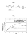
- FIG. 3 is a schematic diagram which illustrates such a conventional apparatus.
- the apparatus illustrated in FIG. 3 has a problem in that because it is necessary to feed a large amount of calcium carbonate in order to increase the probability of contact between SO 3 and calcium carbonate, the operation cost is high due to the increase in the consumption of calcium carbonate. Furthermore, another problem may arise in that because a large amount of calcium carbonate is used, the ratio of the calcium contents in relation to sulfur contents is excessively high, and thus, the purity of gypsum generated by the desulfurization apparatus 5 may degrade. In addition, yet another problem may arise such that because an excessively large amount of calcium carbonate is used, the level of dust concentration at the outlet of a flue gas desulfurization apparatus may be high.
- the present invention has been devised in consideration of the above-described problems, and an object of the present invention is to provide a flue gas treatment apparatus and a flue gas treatment method capable of further greatly reducing operation costs compared with a conventional apparatus while maintaining efficiency of removing SO 3 at or above a specific level.
- a flue gas treatment apparatus for removing sulfur contents contained in combustion flue gas comprises treatment agent feeding means for feeding a treatment agent into a flue through which the combustion flue gas flows, temperature decreasing means for cooling the combustion flue gas to which the treatment agent has been fed to condense SO 3 components in the combustion flue gas, an electric dust collection apparatus provided in a flue arranged on a downstream side of the temperature decreasing means in a direction of flow of flue gas, a desulfurization apparatus based on a lime-gypsum process, provided at a downstream side of the electric dust collection apparatus in a direction of flow of the flue gas, and circulation means for feeding a portion of dust particles recovered by the electric dust collection apparatus into a flue arranged on an upstream side of the temperature decreasing means in the direction of flow of the flue gas for circulated use of the portion of the dust particles as the treatment agent.
- a flue gas treatment method for removing sulfur contents contained in combustion flue gas comprises feeding a treatment agent into a flue through which the combustion flue gas flows, cooling the combustion flue gas to which the treatment agent has been fed by using a temperature decreasing means, removing dust from the cooled combustion flue gas by using an electric dust collection apparatus, and treating the combustion flue gas from which the dusts have been removed by using a desulfurization apparatus based on a lime-gypsum process, and in the method, a portion of the dust particles recovered by the electric dust collection apparatus is fed into a flue arranged on an upstream side of the temperature decreasing means for circulated use of the portion of the dust particles as the treatment agent.
- the present invention can provide a flue gas treatment apparatus and a flue gas treatment method capable of greatly reducing operational costs while maintaining the efficiency of removing SO 3 at or above a specific level at the same time.
- the present invention provides a flue gas treatment apparatus for removing sulfur contents contained in combustion flue gas, which comprises treatment agent feeding means for feeding a treatment agent into a flue through which combustion flue gas flows, temperature decreasing means for cooling the combustion flue gas to which the treatment agent has been fed to condense SO 3 components in the combustion flue gas, an electric dust collection apparatus provided in the flue arranged on a downstream side of the temperature decreasing means in the direction of flow of flue gas, a desulfurization apparatus based on a lime-gypsum process that is provided on a downstream side of the electric dust collection apparatus in the direction of flow of the flue gas, and circulation means for feeding a portion of dust particles recovered by the electric dust collection apparatus into a flue arranged on an upstream side of the temperature decreasing means in the direction of flow of the flue gas for circulated use of the fed dust particles as the treatment agent.
- the powder for the treatment be selected from the group consisting of calcium carbonate, activated carbon, ash, and gypsum.
- the flue gas treatment apparatus of the present invention preferably further comprises reusing means for feeding another portion of the dust particles recovered by the electric dust collection apparatus to the desulfurization apparatus.
- D(t) denotes an amount of the dust particles to be disposed of after the recovery by the
- the powder for the treatment is preferably calcium carbonate or activated carbon.
- the present invention provides a flue gas treatment method for removing sulfur contents contained in combustion flue gas, comprising feeding a treatment agent into a flue through which the combustion flue gas flows, cooling the combustion flue gas to which the treatment agent has been fed by using temperature decreasing means, removing dust from the cooled combustion flue gas by using an electric dust collection apparatus, and treating the combustion flue gas after the dusts have been removed therefrom by using a desulfurization apparatus based on a lime-gypsum process, in which method some of the dust particles recovered by the electric dust collection apparatus is fed into a flue arranged on an upstream side of the temperature decreasing means for circulated use of the portion of the dust particles as the treatment agent.
- the powder for the treatment is preferably selected from the group consisting of calcium carbonate, activated carbon, ash, and gypsum.
- the flue gas treatment method of the present invention preferably further comprises feeding another portion of the recovered dust particles into the desulfurization apparatus to reuse the same in the desulfurization.
- an amount of the dust particles to be disposed of an amount of the dust particles to be circulated for reuse, an amount of the treatment agent to be additionally fed, an amount of the dust particles to be reused in the desulfurization apparatus, and an amount of the desulfurization agent to be additionally fed to the desulfurization apparatus to satisfy, at a time (t), the following expressions (II):
- D t Z t ⁇ Y / X 0 + Y ⁇ K 2 t
- R SO 2 ⁇ t F
- D(t) denotes an amount of the dust particles to be disposed of after the dust
- the powder for the treatment is preferably calcium carbonate or activated carbon.
- the flue gas treatment apparatus and the flue gas treatment method of the present invention will be described in more detail below.
- the present invention is not limited to the following embodiments.
- FIG. 1 illustrates one embodiment of the flue gas treatment apparatus of the present invention.
- the flue gas treatment apparatus illustrated in FIG. 1 comprises treatment agent feeding means 2, temperature decreasing means 3, an electric dust collection apparatus 4, a desulfurization apparatus 5, and a circulation line 6 as its main components.
- the temperature decreasing means 3, the electric dust collection apparatus 4, and the desulfurization apparatus 5 are arranged in this order via a flue.
- the flue gas treatment apparatus of this embodiment includes the temperature decreasing means 3 that is arranged via a flue 11 on a downstream side of a boiler 1 in the direction of flow of the flue gas.
- the treatment agent feeding means 2 is connected to the flue 11 which connects the boiler 1 and the temperature decreasing means 3.
- the electric dust collection apparatus 4 is provided in the flue 11 arranged on a downstream side of the temperature decreasing means 3 in the direction of flow of the flue gas.
- a dust particle transport line 12 is connected to the electric dust collection apparatus 4, and the dust particle transport line 12 is branched from distribution means 9 as the starting point, into a circulation line 6, which is connected to the flue 11 that connects the boiler 1 with the temperature decreasing means 3, and into a waste line 14, which is a line for disposing of the remaining dust particles.
- the desulfurization apparatus 5, which is connected via the flue 11, is arranged on a downstream side of the electric dust collection apparatus 4 in the direction of flow of the flue gas.
- a calcium carbonate feeding means 8 is connected to the desulfurization apparatus 5 via a pipe line.
- a stack 13, which is connected via the flue, is arranged on a downstream side of the desulfurization apparatus 5 in the direction of flow of the flue gas.
- the boiler 1 is arranged on an upstream side of the flue gas treatment apparatus in the direction of flow of the flue gas, burns a fossil fuel such as heavy oil and coal, and exhausts the flue gas. It is suitable if the boiler 1 uses a fuel, such as heavy oil, having a high sulfur content and a low ash content and generating a large amount of SO 3 .
- a boiler such as a coal Integrated Gasification Combined Cycle (IGCC) boiler is suitable.
- apparatuses such as a denitrification apparatus, an electric dust collection apparatus, and a heat recovery apparatus may be installed.
- the treatment agent feeding means 2 is means for feeding a treatment agent 102 into the flue 11 through which combustion flue gas 100 flows.
- the treatment agent feeding means 2 is connected to the flue 11 that connects the boiler 1 with the temperature decreasing means 3.
- Examples of the treatment agent feeding means 2 include a device constituted by a tank or a hopper for storing the treatment agent 102, a pipe line that connects the treatment agent tank or hopper with the flue 11, and means for conveying the treatment agent 102 from the treatment agent tank or hopper via the pipe line, and the like.
- Examples of the means for conveying the treatment agent 102 include a blower or an air compressor, and the like as gas-flow conveyance means.
- Examples of the means for conveying the treatment agent 102 by slurry conveyance include a device constituted by a stirring tank, in which particles of a treatment agent are mixed into liquid to convert the liquid into slurry, and a slurry pump, which is a pump for pressure-feeding the slurry produced in the stirring tank. It is suitable if a means for injecting the treatment agent 102 into the combustion flue gas in the flue 11, e.g., an injection grid having a plurality of injection nozzles, for example, is provided at an outlet port of the pipe line.
- the amount of the treatment agent to be fed from the treatment agent feeding means 2 is preferably controlled by a control device 7, which will be described below.
- the treatment agent 102 is preferably solid particles selected from the group consisting of calcium carbonate, activated carbon, ash, and gypsum.
- the treatment agent has an action of adsorbing SO 3 mist contained in the combustion flue gas in the flue.
- activated carbon has an action of binding to organic matter (e.g., a component for detecting total organic carbon (TOC) such as humic acid), heavy metals (e.g., Hg), HCl, and H 2 S, and thereby, it is enabled to remove these substances from the combustion flue gas.
- TOC total organic carbon
- the treatment agent is fed as a slurry, it is preferable to use liquid that immediately vaporizes due to heat from the combustion flue gas as the liquid constituting the slurry so as to achieve a high level of action of adsorbing SO 3 on the surfaces of particles of the treatment agent, and commonly used water such as industrial water, for example, can be used as the liquid described above.
- the temperature decreasing means 3 is a means for cooling the combustion flue gas 100 to which the treatment agent 102 has been fed and condense the SO 3 components in the combustion flue gas.
- the temperature decreasing means 3 is provided via the flue 11 on a downstream side of the boiler 1 in the direction of flow of the flue gas.
- the temperature decreasing means 3 decreases the temperature of the flue gas, preferably to 90 to 150°C.
- the temperature decreasing means 3 is not limited to a particular device and any device capable of decreasing the temperature of the flue gas to the extent that the SO 3 components condense can be used, and examples of the temperature decreasing means 3 include a heat recovery device such as a gas-gas heater (GGH), a cooling spray device configured to inject a cooling medium into flue gas, and the like.
- GGH gas-gas heater
- the electric dust collection apparatus 4 is a means for removing dust from the flue gas that has been cooled by the temperature decreasing means 3.
- the treatment agent that has been brought into contact with the combustion flue gas 100 is recovered as the dust particles 101.
- the electric dust collection apparatus 4 is provided in the flue 11 arranged on a downstream side of the temperature decreasing means 3 in the direction of flow of the flue gas.
- the dust particle transport line 12 for transporting the recovered dust particles is connected.
- the dust particle transport line 12 is branched from the distribution means 9 as the starting point, into the circulation line 6, which is connected to the flue 11 that connects the boiler 1 with the temperature decreasing means 3, and into the waste line 14, which is a line for disposing of the remaining dust particles.
- the distribution means 9 includes, for example, a combination of a hopper for receiving the dust particles 101 that have been transported thereto, two valves branched therefrom into the circulation line 6 and the waste line 14, and conveyers or blowers configured to transport the smoke and dust into the lines.
- a flowmeter configured to measure the flow rate of the dust particles 101 conveyed from the electric dust collection apparatus 4 and an SO 3 concentration measuring device configured to measure the concentration of SO 3 in the dust particles 101 are connected to the dust particle transport line 12 on an upstream side of the distribution means 9 in the direction of flow of the dust particles. Measurement values measured by the flowmeter and the SO 3 concentration measuring device are output to the control means 7.
- the circulation line 6 is a line for feeding dust particles into the flue 11 as a powder or slurry.
- the circulation line 6 preferably includes gas-flow conveyance means configured to gas-flow convey dust particles, such as a blower or an air compressor, or a slurry-conveyance means, which includes a combination of a stirring tank in which dust particles are mixed into liquid to convert the liquid into slurry and a slurry pump for pressure-feeding the slurry produced in the stirring tank.
- a means for injecting the dust particles into the combustion flue gas e.g., an injection grid having a plurality of injection nozzles, etc., be provided at an outlet port of the circulation line 6 at the flue 11.
- the desulfurization apparatus 5 is a means for removing SO 2 components in the combustion flue gas on the basis of a lime-gypsum process.
- the desulfurization apparatus 5 is provided on a downstream side of the electric dust collection apparatus 4 in the direction of flow of the flue gas, via the electric dust collection apparatus 4 and the flue 11.
- a known apparatus can be used as the desulfurization apparatus 5, e.g., an apparatus including an absorption column, in which sulfur contents in combustion flue gas are absorbed by an absorbing solution containing calcium carbonate as its main component, can be used.
- the calcium carbonate feeding means 8 for feeding calcium carbonate 103 for preparation of the absorbing solution is connected to the desulfurization apparatus 5 via a pipe line.
- the calcium carbonate feeding means 8 includes a hopper for storing calcium carbonate, for example.
- the desulfurization apparatus 5 may be connected to an apparatus, such as a belt filter, which is configured to transport gypsum slurry generated in the absorption column of the desulfurization apparatus 5 from a discharge port for dehydration and recovery thereof.
- the stack 13 is arranged via the flue 11 on a downstream side of the desulfurization apparatus 5 in the direction of flow of the flue gas and is configured to discharge the flue gas to an outside of the flue gas treatment apparatus.
- the control means 7 is configured to control the amount of the dust particles to be disposed of, the amount of the dust particles to be circulated for reuse, and the amount of the treatment agent to be additionally fed, on the basis of the measurement values output from the flowmeter for the dust particles and the SO 3 concentration measuring device.
- the control means 7 controls the amount of the dust particles to be disposed of by controlling the degree of opening of the waste hopper and by adjusting the output from the blower, for example.
- the amount of the dust particles to be circulated and used is controlled by a combined control of the conveyor and the degree of opening of the hopper, for example.
- the amount of the treatment agent to be additionally fed is controlled on the basis of the degree of opening of the hopper, for example.
- D(t) denotes an amount of dust particles to be disposed of among the dust particles recovered by the electric dust collection apparatus 4.
- Z(t) denotes the total amount of the dust particles that have been recovered by the electric dust collection apparatus 4 per unit time (unit: ton/h), and the total amount of the dust particles is calculated on the basis of measurement values that have been measured by the flowmeter for measuring the flow rate of the dust particles 101, which is arranged on an upstream side of the distribution means 9 provided in the dust particle transport line 12 in the direction of flow of the dust particles.
- X 0 denotes the amount of the treatment agent to be fed before the circulation of the dust particles is started (unit: ton/h), and this amount corresponds to the amount of the treatment agent required for removing the SO 3 component in the combustion flue gas until the level of the SO 3 component is decreased to 0 ppm when the flue gas is treated without circulating the dust particles.
- the value of X 0 can be determined as a value about 10 to 30 times the value of the mass of SO 3 entrained in combustion flue gas.
- Y denotes an amount of SO 3 to be removed from the combustion flue gas (unit: ton/h), and this amount can be measured by the SO 3 concentration measuring device which measures the concentration of SO 3 in the dust particles 101 and is provided on an upstream side of the distribution means 9 arranged in the dust particle transport line 12 in the direction of flow of the dust particles.
- K 1 (t) denotes the correction amount of the dust particles to be disposed of, and this amount is adjusted so that the purity of the treatment agent will not degrade due to repeated circulation of the dust particles.
- K 1 (t) can be a freely selected value and can be a constant or a variable. It is preferable that mass balance calculations be previously carried out to determine K 1 (t), and K 1 (t) may be preferably determined to have a value for maintaining a high effective concentration of the treatment agent component, i.e., a value for maintaining a high level of concentration of the treatment agent available for removal of SO 3 , after the circulation of the dust particles has reached a stable state.
- the mass balance calculations can be carried out by performing calculations by the expressions (I) in consideration of changes with time.
- the effective concentration of the treatment agent component when the circulation of the dust particles has reached the stable state be 60% by mass or higher, more preferably 70% by mass or higher, in relation to the entirety of the substances recovered by the electric dust collection apparatus 4, or it is preferable that the concentration of SO 3 recovered by the electric dust collection apparatus 4 when the circulation of the dust particles has reached the stationary state be 40% by mass or less, and more preferably 30% by mass.
- K 1 (t) may have a value of 2.5 or more, preferably, and may more preferably have a value ranging from 3.5 to 4.0.
- K 1 (t) By controlling the values of K 1 (t) within the above-described range, it is made possible to carry out control so that the stable state of the dust particles can be maintained, in which the concentration of SO 3 in the dust particles is restricted to be at a specific level or less and degradation of the rate of removal of SO 3 that may occur due to the circulated use of the dust particles is prevented.
- FIG. 4 is a graph illustrating calculation values of the concentration of SO 3 in the dust particles obtained by setting to various values the correction amount K 1 (t) of the dust particles to be disposed of.
- the concentration of SO 3 in the dust particles can be considered to be the same as the ratio of off-quality calcium carbonate in the dust particles.
- the calculation values were obtained for a case in which calcium carbonate was used as the treatment agent.
- K 1 (t) a value of 1, 1.50, 2, 3, or 10 was used, or a value of 2 was set thereto at the start of the circulation, and a value of 3.5 was set when 6 hours had elapsed since the start of the circulation.
- FIG. 5 illustrates the ratio of calcium carbonate to be additionally fed for removal of SO 3 , which is fed from the treatment agent feeding means 2.
- the graph illustrated in FIG. 5 has been generated by performing calculations under the same conditions as those used for the case illustrated in FIG. 4 .
- the flue gas treatment method of this embodiment includes feeding the treatment agent 102 into the flue 11 through which the combustion flue gas 100 flows, cooling the combustion flue gas 100 to which the treatment agent 102 has been fed, by using the temperature decreasing means 3, removing dust from the cooled combustion flue gas by using the electric dust collection apparatus 4, and treating the combustion flue gas after the dust has been removed therefrom by using the desulfurization apparatus 5 on the basis of the lime-gypsum process, and in the flue gas treatment method, in which a portion of the dust particles 101 recovered by the electric dust collection apparatus 4 is fed into the flue 11 provided on an upstream side of the temperature decreasing means for circulated use of the portion of the dust particles 101 as the treatment agent.
- the treatment agent 102 is fed by the treatment agent feeding means 2 into the flue 11, which is arranged on a downstream side of the boiler 1 and on an upstream side of the temperature decreasing means 3 in the direction of flow of the flue gas.
- the treatment agent 102 can be fed into the flue 11 as a powder or slurry.
- the amount of the treatment agent 102 to be fed is controlled by the control means 7.
- the treatment agent 102 is preferably injected into the combustion flue gas in the flue 11 and uniformly dispersed therein.
- the combustion flue gas 100 is cooled by the temperature cooling means 3 to condense the SO 3 component in the combustion flue gas.
- the flue gas 100 is preferably cooled to have a temperature ranging from 90 to 150°C.
- the SO 3 mist is adsorbed by the treatment agent in the combustion flue gas and is carried by the flue gas stream to the electric dust collection apparatus 4 together with the treatment agent.
- the treatment agent to which the SO 3 components have been adsorbed from the combustion flue gas is separated and recovered as dust particles by using the electric dust collection apparatus 4.
- the SO 3 mist is substantially completely removed from the combustion flue gas and substantially no SO 3 remains in the combustion flue gas after the dust is removed.
- the recovered dust particles are transported to the dust particle transport line 12, a part thereof is transported into the circulation line 6 via the distribution means 9, and the other portion of the dust particles is disposed of via the waste line 14.
- the amount of the dust particles to be transported to the circulation line 6 and the amount of the dust particles to be disposed of are controlled by the control means 7.
- the combustion flue gas after the dust has been removed therefrom undergoes desulfurization by the desulfurization apparatus 5 on the basis of the lime-gypsum process.
- calcium carbonate 103 is fed by the calcium carbonate feeding means 8 for preparation of an absorbing solution used in the lime-gypsum process.
- the amount of calcium carbonate 103 to be fed can be determined on the basis of a concentration of SO 2 at the inlet, a required desulfurization ratio, and a required purity of gypsum.
- sulfur contents in the combustion flue gas primarily SO 2 components
- Gypsum slurry precipitates in the absorbing solution, and the precipitated gypsum slurry is dehydrated by a belt filter or the like, for example, and is recovered as gypsum.
- activated carbon is used as the treatment agent, Hg in the absorbing solution is adsorbed by activated carbon and is thereby removed from the combustion flue gas.
- Combustion flue gas that has been exhausted from the desulfurization apparatus 5 is discharged from the stack 13.
- the treatment agent for the combustion flue gas can be used in a circulating manner, which thereby enables reduction of the amount of the treatment agent to be fed, and as a result, the operation costs can be reduced. Further, by controlling the ratio of the treatment agent to be circulated and used, the concentration of the effective component of the treatment agent can be maintained to a specific level or higher and degradation of the ratio of removed SO 3 that may occur due to circulated use of the treatment agent can be prevented.
- the combustion flue gas undergoes dust removal by the electric dust collection apparatus 4, the treatment agent will not flow into the desulfurization apparatus 5 without being treated, and thus calcium contents in the gypsum will not become excessive. Therefore, there will be no problem that the purity of gypsum to be produced may degrade or that the concentration of smoke and dust will be high at the outlet of the desulfurization apparatus.
- FIG. 2 illustrates a second embodiment of the flue gas treatment apparatus of the present invention.
- the flue gas treatment apparatus shown in FIG. 2 includes, as main components, the treatment agent feeding means 2, the temperature decreasing means 3, the electric dust collection apparatus 4, the desulfurization apparatus 5, the circulation line 6, and a feed line 10.
- the temperature decreasing means 3, the electric dust collection apparatus 4, and the desulfurization apparatus 5 are arranged in this order via the flue.
- the flue gas treatment apparatus of the present embodiment is characterized in that a portion of the dust particles recovered by the electric dust collection apparatus 4 is fed into the flue 11 arranged upstream of the temperature decreasing means 3 in the direction of flow of the flue gas to circulate and use a portion of the dust particles as the treatment agent, and in addition, this embodiment is characterized in that another portion of the dust particles 101 is fed to the desulfurization apparatus 5.
- the components provided with the same reference numerals as those in FIG. 1 have similar configurations and actions as those illustrated in FIG. 1 .
- the flue gas treatment apparatus of this embodiment further includes the feed line 10, which is provided at the dust particle transport line 12 and is branched from the distribution means 9 as the starting point, and is connected to the desulfurization apparatus 5.
- the distribution means 9 includes, for example, a combination of a hopper for receiving the dust particles 101 that have been transported thereto, three valves that branch into the circulation line 6, the waste line 14, and the feed line 10, and conveyers or blowers configured to transport smoke and dust into the lines.
- the feed line 10 feeds another portion of the dust particles different from the portion of the dust particles to be transported to the circulation line 6, among the dust particles 101 that have been recovered by the electric dust collection apparatus 4, to the desulfurization apparatus 5 to reuse another portion of the dust particles for preparation of an absorbing solution.
- the amount of dust particles to be fed to the desulfurization apparatus 5 via the feed line 10 is determined by the control means 7.
- the treatment agent 102 is calcium carbonate or activated carbon. If activated carbon is used, not only SO 3 components, but also organic matter (components for detecting TOC such as humic acid), heavy metals (e.g., Hg), HCl, and H 2 S can be adsorbed and removed from the combustion flue gas.
- activated carbon not only SO 3 components, but also organic matter (components for detecting TOC such as humic acid), heavy metals (e.g., Hg), HCl, and H 2 S can be adsorbed and removed from the combustion flue gas.
- an SO 2 concentration measuring device configured to measure the concentration of SO 2 in the combustion flue gas that flows out of the desulfurization apparatus 5 is provided in the flue 11, which connects the desulfurization apparatus 5 with the stack 13. Measurement values measured by the SO 2 concentration measuring device are output to the control means 7.
- the control means 7 controls the amount of the dust particles to be disposed of, the amount of the dust particles to be circulated for reuse, the amount of the treatment agent to be additionally fed, the amount of the dust particles to be reused in the desulfurization apparatus, and the amount of a desulfurization agent to be additionally fed to the desulfurization apparatus on the basis of measurement values output from the flowmeter, the SO 3 concentration measuring device, and the SO 2 concentration measuring device.
- the control means 7 controls the amount of dust particles to be disposed of by controlling the degree of opening of the waste hopper and by adjusting the output from the blower, for example.
- the amount of the dust particles to be circulated for reuse is controlled by combined control of the conveyor and the degree of opening of the hopper, for example.
- the amount of the treatment agent to be additionally fed is controlled on the basis of the degree of opening of the hopper, for example.
- the amount of the dust particles to be reused in the desulfurization apparatus is controlled by a combined control of the conveyor and the degree of opening of the hopper, for example.
- the amount of the desulfurization agent to be additionally fed to the desulfurization apparatus is controlled on the basis of the degree of opening of the hopper, for example.
- D(t) denotes an amount of the dust particles to be disposed of among the dust particles recovered by the electric dust collection apparatus 4.
- Z(t) denotes the total amount of the dust particles that have been recovered by the electric dust collection apparatus 4 per unit time (unit: ton/h), and this amount is calculated on the basis of measured values measured by the flowmeter for measuring the flow rate of the dust particles 101, which is provided on an upstream side of the distribution means 9 arranged in the dust particle transport line 12 in the direction of flow of the dust particles.
- X 0 denotes the amount of the treatment agent to be fed before the circulation is started (unit: ton/h), and this amount corresponds to the amount of the treatment agent required for removing the SO 3 component in the combustion flue gas to the extent that the level of the SO 3 component is decreased to 0 ppm if the flue gas is treated without circulating the dust particles.
- the value of X 0 can be determined as a value about 10 to 30 times the value of the mass of SO 3 entrained in the gas.
- Y denotes an amount of SO 3 to be removed from the combustion flue gas (unit: ton/h), and this amount can be measured by the SO 3 concentration measuring device which measures the concentration of SO 3 in the dust particles 101 and is provided upstream of the distribution means 9 arranged in the dust particle transport line 12 in the direction of flow of the dust particles.
- F denotes the amount of calcium carbonate required in the desulfurization apparatus 5, and this amount can be calculated on the basis of the concentration of SO 2 at the inlet, a required desulfurization rate, a required purity of the gypsum, and the like.
- R(SO 3 )(t) denotes the amount of the dust particles to be circulated by the circulation line 6 for reuse (unit: ton/h)
- X(SO 3 )(t) denotes the amount of the treatment agent to be additionally fed (unit: ton/h)
- R(SO 2 )(t) denotes the amount of the dust particles to be reused in the desulfurization apparatus 5 (unit: ton/h)
- X(SO 2 )(t) denotes the amount of calcium carbonate to be additionally fed to the desulfurization apparatus 5 (unit: ton/h)
- K 2 (t) denotes the correction amount of the dust particles to be disposed of, and this amount is adjusted so that the purity of the treatment agent may not degrade due to repeated circulation of the dust particles.
- K 2 (t) may be a constant or a variable.
- K 2 (t) can have a freely selected value, and it is preferable that mass balance calculations be previously carried out to determine K 2 (t), and K 2 (t) may be preferably determined to have a value for maintaining a high effective concentration of the treatment agent component after the circulation of the dust particles has reached a stable state, i.e., it is preferable to determine K 2 (t) so that it may have a value for maintaining a high level of concentration of the treatment agent available for removal of SO 3 , preferably as high as 60% by mass or more, more preferably as high as 70% by mass or more, in the dust particles recovered by the electric dust collection apparatus 4.
- the mass balance calculations can be carried out by time-serially performing calculations by the expressions (II).
- the flue gas treatment method according to this embodiment is different from the first embodiment in that it further includes a step of feeding another portion of the dust particles recovered by the electric dust collection apparatus 4 into the desulfurization apparatus 5 to be reused there.
- the flue gas treatment apparatus of this embodiment and the flue gas treatment method that uses the apparatus can achieve the effects of reducing the operation costs by reducing the amount of the treatment agent to be fed and maintain the ratio of removal of SO 3 to a specific level or higher at the same time, and can also achieve the effect of controlling the sulfur contents coming into the desulfurization apparatus 5 within an appropriate range, and thereby the purity of gypsum generated by the desulfurization apparatus 5 can be steadily maintained at a high level.
Landscapes
- Engineering & Computer Science (AREA)
- Chemical & Material Sciences (AREA)
- Environmental & Geological Engineering (AREA)
- Health & Medical Sciences (AREA)
- Biomedical Technology (AREA)
- Analytical Chemistry (AREA)
- General Chemical & Material Sciences (AREA)
- Oil, Petroleum & Natural Gas (AREA)
- Chemical Kinetics & Catalysis (AREA)
- Life Sciences & Earth Sciences (AREA)
- Sustainable Development (AREA)
- Treating Waste Gases (AREA)
Abstract
Description
- The present invention relates to a flue gas treatment apparatus and to a flue gas treatment method for removing sulfur contained in combustion flue gas.
- Fossil fuels such as heavy oil, coal, and the like contain sulfur, and when such a fossil fuel is combusted in a boiler or the like, the sulfur contents are oxidized in a furnace and most of it is oxidized into sulfur dioxide (SO2) gas, and some of the sulfur dioxide gas is further oxidized to be converted into sulfur trioxide (SO3) gas. When SO3 gas is cooled in a smoke exhaust system, the cooled SO3 gas turns into sulfuric acid (SO3) mist. SO3 mist consists of condensed sulfuric acid, and if coal is used as the fuel, SO3 mist does not cause corrosion because SO3 mist is "sprinkled" over a large amount of coal ash; on the other hand, if a fuel containing low ash content such as oil is used, SO3 mist may often cause corrosion because the content of ash over which SO3 mist is to be "sprinkled" is low. In particular, if a fuel including very high sulfur contents such as heavy oil is used, a large amount of SO3 is generated, and thus, corrosion due to SO3 that may occur in devices such as a dust collection apparatus and a flue that are installed in the smoke exhaust system has become a serious problem.
- SO3 mist consists of fine particles that are precipitated in a vapor phase and are difficult to collect even if a flue gas desulfurization apparatus is installed, and most of it may remain uncollected and pass through the gas desulfurization apparatus to be released from the stack as violet smoke. Therefore, a conventional flue gas treatment facility provided for power generation equipment in which the flue gas includes low ash content and the amount of generated SO3 is large (i.e., the conversion rate of S is high) has been known, in which calcium carbonate (CaCO3) is fed by injection for adsorption of SO3 at a location downstream of a denitrification apparatus, and thus, SO3 is separated and removed as gypsum to prevent corrosion of equipment that may occur due to SO3 (Patent Literature 1).
- In addition, a conventional apparatus has been known, in which the temperature of the flue gas is lowered to a temperature at which SO3 in the flue gas changes into SO3 fumes, the SO3 fumes are adsorbed to charged solid particles such as calcium carbonate that has been electrically charged, and thereby, SO3 is separated and removed (Patent Literature 2).
FIG. 3 is a schematic diagram which illustrates such a conventional apparatus. - In the apparatus illustrated in the drawing, calcium carbonate is injected by calcium carbonate feeding means 22 into combustion flue gas, the combustion flue gas is cooled by temperature lowering
means 3, and thereby SO3 is condensed and adsorbed by calcium carbonate. In adesulfurization apparatus 5, the remaining calcium carbonate that has not reacted with SO3 is used as a material for the lime-gypsum method and SO2 is separated as gypsum. -
- Patent Literature 1:
JP 2001-145818 A - Patent Literature 2:
JP 2007-245074 A - However, the apparatus illustrated in
FIG. 3 has a problem in that because it is necessary to feed a large amount of calcium carbonate in order to increase the probability of contact between SO3 and calcium carbonate, the operation cost is high due to the increase in the consumption of calcium carbonate. Furthermore, another problem may arise in that because a large amount of calcium carbonate is used, the ratio of the calcium contents in relation to sulfur contents is excessively high, and thus, the purity of gypsum generated by thedesulfurization apparatus 5 may degrade. In addition, yet another problem may arise such that because an excessively large amount of calcium carbonate is used, the level of dust concentration at the outlet of a flue gas desulfurization apparatus may be high. - The present invention has been devised in consideration of the above-described problems, and an object of the present invention is to provide a flue gas treatment apparatus and a flue gas treatment method capable of further greatly reducing operation costs compared with a conventional apparatus while maintaining efficiency of removing SO3 at or above a specific level.
- In order to achieve the above object, according to an aspect of the present invention, a flue gas treatment apparatus for removing sulfur contents contained in combustion flue gas comprises treatment agent feeding means for feeding a treatment agent into a flue through which the combustion flue gas flows, temperature decreasing means for cooling the combustion flue gas to which the treatment agent has been fed to condense SO3 components in the combustion flue gas, an electric dust collection apparatus provided in a flue arranged on a downstream side of the temperature decreasing means in a direction of flow of flue gas, a desulfurization apparatus based on a lime-gypsum process, provided at a downstream side of the electric dust collection apparatus in a direction of flow of the flue gas, and circulation means for feeding a portion of dust particles recovered by the electric dust collection apparatus into a flue arranged on an upstream side of the temperature decreasing means in the direction of flow of the flue gas for circulated use of the portion of the dust particles as the treatment agent.
- According to another aspect of the present invention, a flue gas treatment method for removing sulfur contents contained in combustion flue gas comprises feeding a treatment agent into a flue through which the combustion flue gas flows, cooling the combustion flue gas to which the treatment agent has been fed by using a temperature decreasing means, removing dust from the cooled combustion flue gas by using an electric dust collection apparatus, and treating the combustion flue gas from which the dusts have been removed by using a desulfurization apparatus based on a lime-gypsum process, and in the method, a portion of the dust particles recovered by the electric dust collection apparatus is fed into a flue arranged on an upstream side of the temperature decreasing means for circulated use of the portion of the dust particles as the treatment agent.
- The present invention can provide a flue gas treatment apparatus and a flue gas treatment method capable of greatly reducing operational costs while maintaining the efficiency of removing SO3 at or above a specific level at the same time.
-
-
FIG. 1 is a system diagram which illustrates an embodiment of an entire configuration of a flue gas treatment apparatus of the present invention. -
FIG. 2 is a system diagram which illustrates another embodiment of an entire configuration of a flue gas treatment apparatus according to the present invention. -
FIG. 3 is a system diagram which illustrates a flue gas treatment apparatus according to a prior art. -
FIG. 4 is a diagram which illustrates a concentration of SO3 in dust particles. -
FIG. 5 is a diagram which illustrates a ratio of additional feed (= additional feed amount/initial feed amount) of calcium carbonate used for removal of SO3. - The present invention provides a flue gas treatment apparatus for removing sulfur contents contained in combustion flue gas, which comprises treatment agent feeding means for feeding a treatment agent into a flue through which combustion flue gas flows, temperature decreasing means for cooling the combustion flue gas to which the treatment agent has been fed to condense SO3 components in the combustion flue gas, an electric dust collection apparatus provided in the flue arranged on a downstream side of the temperature decreasing means in the direction of flow of flue gas, a desulfurization apparatus based on a lime-gypsum process that is provided on a downstream side of the electric dust collection apparatus in the direction of flow of the flue gas, and circulation means for feeding a portion of dust particles recovered by the electric dust collection apparatus into a flue arranged on an upstream side of the temperature decreasing means in the direction of flow of the flue gas for circulated use of the fed dust particles as the treatment agent.
- In one embodiment, the flue gas treatment apparatus of the present invention preferably further comprises control means for controlling an amount of dust particles to be disposed of, an amount of dust particles to be circulated for reuse, and an amount of treatment agent to be additionally fed so as to satisfy, at a time (t), the following expressions (I):


wherein D(t) denotes an amount of the dust particles to be disposed of among the dust particles recovered by the electric dust collection apparatus, Z(t) denotes the total amount of dust particles recovered by the electric dust collection apparatus, X0 denotes an amount of the treatment agent to be fed before the circulation is started, Y denotes an amount of SO3 to be removed from the combustion flue gas, R(SO3)(t) denotes an amount of the dust particles to be circulated for reuse by the circulation means, X(SO3)(t) denotes an amount of the treatment agent to be additionally fed, and K1(t) denotes a correction amount of the dust particles to be disposed of - In one embodiment of the flue gas treatment apparatus of the present invention, it is preferable that the powder for the treatment be selected from the group consisting of calcium carbonate, activated carbon, ash, and gypsum.
- In another embodiment, the flue gas treatment apparatus of the present invention preferably further comprises reusing means for feeding another portion of the dust particles recovered by the electric dust collection apparatus to the desulfurization apparatus.
- In one embodiment, the flue gas treatment apparatus of the present invention further comprises control means for controlling an amount of the dust particles to be disposed of, an amount of the dust particles to be circulated for reuse, an amount of the treatment agent to be additionally fed, an amount of the dust particles to be reused in the desulfurization apparatus, and an amount of desulfurization agent to be additionally fed to the desulfurization apparatus to satisfy, at a time (t), the following expressions (II):


wherein D(t) denotes an amount of the dust particles to be disposed of after the recovery by the electric dust collection apparatus, Z(t) denotes the total amount of the dust particles that have been recovered by the electric dust collection apparatus, X0 denotes an amount of the treatment agent to be fed before the circulation is started, Y denotes an amount of SO3 to be removed from the combustion flue gas, R(SO3)(t) denotes an amount of the dust particles to be circulated for reuse by the circulation means, X(SO3)(t) denotes an amount of the treatment agent to be additionally fed, K(t) denotes a correction amount of the dust particles to be disposed of, R(SO2)(t) denotes an amount of the dust particles to be reused in the desulfurization apparatus, F denotes an amount required in the desulfurization apparatus, and X(SO2)(t) denotes an amount of desulfurization agent to be additionally fed to the desulfurization apparatus. - In one embodiment of the flue gas treatment apparatus of the present invention, the powder for the treatment is preferably calcium carbonate or activated carbon.
- In another aspect, the present invention provides a flue gas treatment method for removing sulfur contents contained in combustion flue gas, comprising feeding a treatment agent into a flue through which the combustion flue gas flows, cooling the combustion flue gas to which the treatment agent has been fed by using temperature decreasing means, removing dust from the cooled combustion flue gas by using an electric dust collection apparatus, and treating the combustion flue gas after the dusts have been removed therefrom by using a desulfurization apparatus based on a lime-gypsum process, in which method some of the dust particles recovered by the electric dust collection apparatus is fed into a flue arranged on an upstream side of the temperature decreasing means for circulated use of the portion of the dust particles as the treatment agent.
- In one embodiment of the flue gas treatment method of the present invention, it is preferable to control an amount of the dust particles to be disposed of, an amount of the dust particles to be circulated and used, and an amount of the treatment agent to be additionally fed so as to satisfy, at a time (t), the following expressions (I):


wherein D(t) denotes an amount of the dust particles to be disposed of among the recovered dust particles, Z(t) denotes the total amount of dust particles recovered by the electric dust collection apparatus, X0 denotes an amount of the treatment agent to be fed before the circulation is started, Y denotes an amount of SO3 to be removed from the combustion flue gas, R(SO3)(t) denotes an amount of the dust particles to be circulated for reuse, X(SO3)(t) denotes an amount of the treatment agent to be additionally fed, and K1(t) denotes a correction amount of the dust particles to be disposed of - In one embodiment of the flue gas treatment method of the present invention, the powder for the treatment is preferably selected from the group consisting of calcium carbonate, activated carbon, ash, and gypsum.
- In another embodiment, the flue gas treatment method of the present invention preferably further comprises feeding another portion of the recovered dust particles into the desulfurization apparatus to reuse the same in the desulfurization.
- In one embodiment of the flue gas treatment method of the present invention, it is preferable to control an amount of the dust particles to be disposed of, an amount of the dust particles to be circulated for reuse, an amount of the treatment agent to be additionally fed, an amount of the dust particles to be reused in the desulfurization apparatus, and an amount of the desulfurization agent to be additionally fed to the desulfurization apparatus to satisfy, at a time (t), the following expressions (II):


wherein D(t) denotes an amount of the dust particles to be disposed of after the dust removal step, Z(t) denotes the total amount of recovered dust particles, X0 denotes an amount of the treatment agent to be fed before the circulation is started, Y denotes an amount of SO3 to be removed from the combustion flue gas, R(SO3)(t) denotes an amount of the dust particles to be circulated for reuse, X(SO3)(t) denotes an amount of the treatment agent to be additionally fed, K(t) denotes a correction amount of the dust particles to be disposed of, R(SO2)(t) denotes an amount of the dust particles to be reused, F denotes an amount required in the desulfurization apparatus, and X(SO2)(t) denotes an amount of desulfurization agent to be additionally fed to the desulfurization apparatus. - In one embodiment of the flue gas treatment method of the present invention, the powder for the treatment is preferably calcium carbonate or activated carbon.
- The flue gas treatment apparatus and the flue gas treatment method of the present invention will be described in more detail below. The present invention is not limited to the following embodiments.
-
FIG. 1 illustrates one embodiment of the flue gas treatment apparatus of the present invention. The flue gas treatment apparatus illustrated inFIG. 1 comprises treatment agent feeding means 2, temperature decreasing means 3, an electricdust collection apparatus 4, adesulfurization apparatus 5, and acirculation line 6 as its main components. The temperature decreasing means 3, the electricdust collection apparatus 4, and thedesulfurization apparatus 5 are arranged in this order via a flue. - The flue gas treatment apparatus of this embodiment includes the temperature decreasing means 3 that is arranged via a
flue 11 on a downstream side of aboiler 1 in the direction of flow of the flue gas. The treatment agent feeding means 2 is connected to theflue 11 which connects theboiler 1 and the temperature decreasing means 3. The electricdust collection apparatus 4 is provided in theflue 11 arranged on a downstream side of the temperature decreasing means 3 in the direction of flow of the flue gas. A dustparticle transport line 12 is connected to the electricdust collection apparatus 4, and the dustparticle transport line 12 is branched from distribution means 9 as the starting point, into acirculation line 6, which is connected to theflue 11 that connects theboiler 1 with the temperature decreasing means 3, and into awaste line 14, which is a line for disposing of the remaining dust particles. Thedesulfurization apparatus 5, which is connected via theflue 11, is arranged on a downstream side of the electricdust collection apparatus 4 in the direction of flow of the flue gas. A calcium carbonate feeding means 8 is connected to thedesulfurization apparatus 5 via a pipe line. Astack 13, which is connected via the flue, is arranged on a downstream side of thedesulfurization apparatus 5 in the direction of flow of the flue gas. - The
boiler 1 is arranged on an upstream side of the flue gas treatment apparatus in the direction of flow of the flue gas, burns a fossil fuel such as heavy oil and coal, and exhausts the flue gas. It is suitable if theboiler 1 uses a fuel, such as heavy oil, having a high sulfur content and a low ash content and generating a large amount of SO3. For example, a boiler such as a coal Integrated Gasification Combined Cycle (IGCC) boiler is suitable. In theflue 11 arranged between theboiler 1 and the flue gas treatment apparatus, apparatuses such as a denitrification apparatus, an electric dust collection apparatus, and a heat recovery apparatus may be installed. - The treatment agent feeding means 2 is means for feeding a
treatment agent 102 into theflue 11 through whichcombustion flue gas 100 flows. The treatment agent feeding means 2 is connected to theflue 11 that connects theboiler 1 with thetemperature decreasing means 3. Examples of the treatment agent feeding means 2 include a device constituted by a tank or a hopper for storing thetreatment agent 102, a pipe line that connects the treatment agent tank or hopper with theflue 11, and means for conveying thetreatment agent 102 from the treatment agent tank or hopper via the pipe line, and the like. Examples of the means for conveying thetreatment agent 102 include a blower or an air compressor, and the like as gas-flow conveyance means. Examples of the means for conveying thetreatment agent 102 by slurry conveyance include a device constituted by a stirring tank, in which particles of a treatment agent are mixed into liquid to convert the liquid into slurry, and a slurry pump, which is a pump for pressure-feeding the slurry produced in the stirring tank. It is suitable if a means for injecting thetreatment agent 102 into the combustion flue gas in theflue 11, e.g., an injection grid having a plurality of injection nozzles, for example, is provided at an outlet port of the pipe line. The amount of the treatment agent to be fed from the treatment agent feeding means 2 is preferably controlled by acontrol device 7, which will be described below. - The
treatment agent 102 is preferably solid particles selected from the group consisting of calcium carbonate, activated carbon, ash, and gypsum. The treatment agent has an action of adsorbing SO3 mist contained in the combustion flue gas in the flue. In addition to the action of adsorbing SO3 mist, activated carbon has an action of binding to organic matter (e.g., a component for detecting total organic carbon (TOC) such as humic acid), heavy metals (e.g., Hg), HCl, and H2S, and thereby, it is enabled to remove these substances from the combustion flue gas. The treatment agent is preferably fed into theflue 11 as a powder or slurry. If the treatment agent is fed as a slurry, it is preferable to use liquid that immediately vaporizes due to heat from the combustion flue gas as the liquid constituting the slurry so as to achieve a high level of action of adsorbing SO3 on the surfaces of particles of the treatment agent, and commonly used water such as industrial water, for example, can be used as the liquid described above. - The
temperature decreasing means 3 is a means for cooling thecombustion flue gas 100 to which thetreatment agent 102 has been fed and condense the SO3 components in the combustion flue gas. Thetemperature decreasing means 3 is provided via theflue 11 on a downstream side of theboiler 1 in the direction of flow of the flue gas. Thetemperature decreasing means 3 decreases the temperature of the flue gas, preferably to 90 to 150°C. Thetemperature decreasing means 3 is not limited to a particular device and any device capable of decreasing the temperature of the flue gas to the extent that the SO3 components condense can be used, and examples of thetemperature decreasing means 3 include a heat recovery device such as a gas-gas heater (GGH), a cooling spray device configured to inject a cooling medium into flue gas, and the like. - The electric
dust collection apparatus 4 is a means for removing dust from the flue gas that has been cooled by thetemperature decreasing means 3. In the electricdust collection apparatus 4, the treatment agent that has been brought into contact with thecombustion flue gas 100 is recovered as thedust particles 101. The electricdust collection apparatus 4 is provided in theflue 11 arranged on a downstream side of thetemperature decreasing means 3 in the direction of flow of the flue gas. At a discharge port of the electricdust collection apparatus 4, the dustparticle transport line 12 for transporting the recovered dust particles is connected. The dustparticle transport line 12 is branched from the distribution means 9 as the starting point, into thecirculation line 6, which is connected to theflue 11 that connects theboiler 1 with thetemperature decreasing means 3, and into thewaste line 14, which is a line for disposing of the remaining dust particles. The distribution means 9 includes, for example, a combination of a hopper for receiving thedust particles 101 that have been transported thereto, two valves branched therefrom into thecirculation line 6 and thewaste line 14, and conveyers or blowers configured to transport the smoke and dust into the lines. A flowmeter configured to measure the flow rate of thedust particles 101 conveyed from the electricdust collection apparatus 4 and an SO3 concentration measuring device configured to measure the concentration of SO3 in thedust particles 101 are connected to the dustparticle transport line 12 on an upstream side of the distribution means 9 in the direction of flow of the dust particles. Measurement values measured by the flowmeter and the SO3 concentration measuring device are output to the control means 7. - The
circulation line 6 is a line for feeding dust particles into theflue 11 as a powder or slurry. Thecirculation line 6 preferably includes gas-flow conveyance means configured to gas-flow convey dust particles, such as a blower or an air compressor, or a slurry-conveyance means, which includes a combination of a stirring tank in which dust particles are mixed into liquid to convert the liquid into slurry and a slurry pump for pressure-feeding the slurry produced in the stirring tank. It is preferable that a means for injecting the dust particles into the combustion flue gas, e.g., an injection grid having a plurality of injection nozzles, etc., be provided at an outlet port of thecirculation line 6 at theflue 11. - The
desulfurization apparatus 5 is a means for removing SO2 components in the combustion flue gas on the basis of a lime-gypsum process. Thedesulfurization apparatus 5 is provided on a downstream side of the electricdust collection apparatus 4 in the direction of flow of the flue gas, via the electricdust collection apparatus 4 and theflue 11. A known apparatus can be used as thedesulfurization apparatus 5, e.g., an apparatus including an absorption column, in which sulfur contents in combustion flue gas are absorbed by an absorbing solution containing calcium carbonate as its main component, can be used. The calcium carbonate feeding means 8 for feedingcalcium carbonate 103 for preparation of the absorbing solution is connected to thedesulfurization apparatus 5 via a pipe line. The calcium carbonate feeding means 8 includes a hopper for storing calcium carbonate, for example. Thedesulfurization apparatus 5 may be connected to an apparatus, such as a belt filter, which is configured to transport gypsum slurry generated in the absorption column of thedesulfurization apparatus 5 from a discharge port for dehydration and recovery thereof. - The
stack 13 is arranged via theflue 11 on a downstream side of thedesulfurization apparatus 5 in the direction of flow of the flue gas and is configured to discharge the flue gas to an outside of the flue gas treatment apparatus. - The control means 7 is configured to control the amount of the dust particles to be disposed of, the amount of the dust particles to be circulated for reuse, and the amount of the treatment agent to be additionally fed, on the basis of the measurement values output from the flowmeter for the dust particles and the SO3 concentration measuring device. The control means 7 controls the amount of the dust particles to be disposed of by controlling the degree of opening of the waste hopper and by adjusting the output from the blower, for example. The amount of the dust particles to be circulated and used is controlled by a combined control of the conveyor and the degree of opening of the hopper, for example. The amount of the treatment agent to be additionally fed is controlled on the basis of the degree of opening of the hopper, for example.
- The control means 7 may preferably carry out control of D(t): the amount of the dust particles to be disposed of; R(SO3)(t): the amount of the dust particles to be circulated and used; and X(SO3)(t): the amount of the treatment agent to be additionally fed so as to satisfy, at a time (t), the following expressions (I):


wherein time (t) denotes a freely selected time after having started the circulation of the dust particles. - In the expressions (I), D(t) denotes an amount of dust particles to be disposed of among the dust particles recovered by the electric
dust collection apparatus 4. Z(t) denotes the total amount of the dust particles that have been recovered by the electricdust collection apparatus 4 per unit time (unit: ton/h), and the total amount of the dust particles is calculated on the basis of measurement values that have been measured by the flowmeter for measuring the flow rate of thedust particles 101, which is arranged on an upstream side of the distribution means 9 provided in the dustparticle transport line 12 in the direction of flow of the dust particles. X0 denotes the amount of the treatment agent to be fed before the circulation of the dust particles is started (unit: ton/h), and this amount corresponds to the amount of the treatment agent required for removing the SO3 component in the combustion flue gas until the level of the SO3 component is decreased to 0 ppm when the flue gas is treated without circulating the dust particles. The value of X0 can be determined as a value about 10 to 30 times the value of the mass of SO3 entrained in combustion flue gas. Y denotes an amount of SO3 to be removed from the combustion flue gas (unit: ton/h), and this amount can be measured by the SO3 concentration measuring device which measures the concentration of SO3 in thedust particles 101 and is provided on an upstream side of the distribution means 9 arranged in the dustparticle transport line 12 in the direction of flow of the dust particles. R(SO3)(t) denotes the amount of the dust particles to be circulated by thecirculation line 6 for reuse (unit: ton/h) and X(SO3)(t) denotes the amount of the treatment agent to be additionally fed (unit: ton/h), and these amounts can be determined on the basis of the expressions (I). It should be kept in mind that because reactions between SO3 and CaCO3 and adsorption of SO3 by CaCO3 occur, the equation Z(t) = X0 + Y would not always hold. - K1(t) denotes the correction amount of the dust particles to be disposed of, and this amount is adjusted so that the purity of the treatment agent will not degrade due to repeated circulation of the dust particles. K1(t) can be a freely selected value and can be a constant or a variable. It is preferable that mass balance calculations be previously carried out to determine K1(t), and K1(t) may be preferably determined to have a value for maintaining a high effective concentration of the treatment agent component, i.e., a value for maintaining a high level of concentration of the treatment agent available for removal of SO3, after the circulation of the dust particles has reached a stable state. The mass balance calculations can be carried out by performing calculations by the expressions (I) in consideration of changes with time. For example, in order to maintain the efficiency of removal of SO3 components at 60% or higher, it is preferable that the effective concentration of the treatment agent component when the circulation of the dust particles has reached the stable state be 60% by mass or higher, more preferably 70% by mass or higher, in relation to the entirety of the substances recovered by the electric
dust collection apparatus 4, or it is preferable that the concentration of SO3 recovered by the electricdust collection apparatus 4 when the circulation of the dust particles has reached the stationary state be 40% by mass or less, and more preferably 30% by mass. Based on the mass balance calculation, K1(t) may have a value of 2.5 or more, preferably, and may more preferably have a value ranging from 3.5 to 4.0. By controlling the values of K1(t) within the above-described range, it is made possible to carry out control so that the stable state of the dust particles can be maintained, in which the concentration of SO3 in the dust particles is restricted to be at a specific level or less and degradation of the rate of removal of SO3 that may occur due to the circulated use of the dust particles is prevented. -
FIG. 4 is a graph illustrating calculation values of the concentration of SO3 in the dust particles obtained by setting to various values the correction amount K1(t) of the dust particles to be disposed of. The concentration of SO3 in the dust particles can be considered to be the same as the ratio of off-quality calcium carbonate in the dust particles. The calculation values were obtained for a case in which calcium carbonate was used as the treatment agent. For the value of K1(t), a value of 1, 1.50, 2, 3, or 10 was used, or a value of 2 was set thereto at the start of the circulation, and a value of 3.5 was set when 6 hours had elapsed since the start of the circulation. For other conditions, the calculations were performed under the following conditions: X0 (the initial feeding amount) = 150 ton/h and Y (the amount of SO3 to be removed) = 10 ton/h. It should be kept in mind that in this calculation, the change in mass occurring due to a reaction between SO3 and the moisture content was not considered. It can be understood from the graph inFIG. 4 that the ratio of off-quality calcium carbonate in the dust particles can be reduced to 30% by mass or less, for example, by setting a low value to the correction amount of the dust particles to be disposed of (e.g., K1(t) = 2) at the start of the circulation and increasing it to a high value (e.g., K1(t) = 3.5) after a specific time, e.g., 6 hours, has elapsed after the start of the circulation. -
FIG. 5 illustrates the ratio of calcium carbonate to be additionally fed for removal of SO3, which is fed from the treatment agent feeding means 2. The graph illustrated inFIG. 5 has been generated by performing calculations under the same conditions as those used for the case illustrated inFIG. 4 . - Next, an embodiment of a flue gas treatment method that uses the flue gas treatment apparatus of the present embodiment will be described. The flue gas treatment method of this embodiment includes feeding the
treatment agent 102 into theflue 11 through which thecombustion flue gas 100 flows, cooling thecombustion flue gas 100 to which thetreatment agent 102 has been fed, by using thetemperature decreasing means 3, removing dust from the cooled combustion flue gas by using the electricdust collection apparatus 4, and treating the combustion flue gas after the dust has been removed therefrom by using thedesulfurization apparatus 5 on the basis of the lime-gypsum process, and in the flue gas treatment method, in which a portion of thedust particles 101 recovered by the electricdust collection apparatus 4 is fed into theflue 11 provided on an upstream side of the temperature decreasing means for circulated use of the portion of thedust particles 101 as the treatment agent. - In the step of feeding the
treatment agent 102 into theflue 11 through which thecombustion flue gas 100 flows, thetreatment agent 102 is fed by the treatment agent feeding means 2 into theflue 11, which is arranged on a downstream side of theboiler 1 and on an upstream side of thetemperature decreasing means 3 in the direction of flow of the flue gas. Thetreatment agent 102 can be fed into theflue 11 as a powder or slurry. The amount of thetreatment agent 102 to be fed is controlled by the control means 7. Thetreatment agent 102 is preferably injected into the combustion flue gas in theflue 11 and uniformly dispersed therein. - In the step of cooling the
combustion flue gas 100, thecombustion flue gas 100 is cooled by the temperature cooling means 3 to condense the SO3 component in the combustion flue gas. Theflue gas 100 is preferably cooled to have a temperature ranging from 90 to 150°C. When thecombustion flue gas 100 is cooled, almost all the SO3 components condense and change into SO3 mist. The SO3 mist is adsorbed by the treatment agent in the combustion flue gas and is carried by the flue gas stream to the electricdust collection apparatus 4 together with the treatment agent. - In the step of removing dust from the combustion flue gas by using the electric
dust collection apparatus 4, the treatment agent to which the SO3 components have been adsorbed from the combustion flue gas is separated and recovered as dust particles by using the electricdust collection apparatus 4. By carrying out this step, the SO3 mist is substantially completely removed from the combustion flue gas and substantially no SO3 remains in the combustion flue gas after the dust is removed. The recovered dust particles are transported to the dustparticle transport line 12, a part thereof is transported into thecirculation line 6 via the distribution means 9, and the other portion of the dust particles is disposed of via thewaste line 14. The amount of the dust particles to be transported to thecirculation line 6 and the amount of the dust particles to be disposed of are controlled by the control means 7. - In the step of carrying out treatment by using the
desulfurization apparatus 5, the combustion flue gas after the dust has been removed therefrom undergoes desulfurization by thedesulfurization apparatus 5 on the basis of the lime-gypsum process. To thedesulfurization apparatus 5,calcium carbonate 103 is fed by the calcium carbonate feeding means 8 for preparation of an absorbing solution used in the lime-gypsum process. The amount ofcalcium carbonate 103 to be fed can be determined on the basis of a concentration of SO2 at the inlet, a required desulfurization ratio, and a required purity of gypsum. By performing the step of carrying out the treatment by thedesulfurization apparatus 5, sulfur contents in the combustion flue gas, primarily SO2 components, are adsorbed into the absorbing solution to produce gypsum. Gypsum slurry precipitates in the absorbing solution, and the precipitated gypsum slurry is dehydrated by a belt filter or the like, for example, and is recovered as gypsum. If activated carbon is used as the treatment agent, Hg in the absorbing solution is adsorbed by activated carbon and is thereby removed from the combustion flue gas. Combustion flue gas that has been exhausted from thedesulfurization apparatus 5 is discharged from thestack 13. - According to the flue gas treatment apparatus and the flue gas treatment method of the first embodiment, the treatment agent for the combustion flue gas can be used in a circulating manner, which thereby enables reduction of the amount of the treatment agent to be fed, and as a result, the operation costs can be reduced. Further, by controlling the ratio of the treatment agent to be circulated and used, the concentration of the effective component of the treatment agent can be maintained to a specific level or higher and degradation of the ratio of removed SO3 that may occur due to circulated use of the treatment agent can be prevented. In this embodiment, the combustion flue gas undergoes dust removal by the electric
dust collection apparatus 4, the treatment agent will not flow into thedesulfurization apparatus 5 without being treated, and thus calcium contents in the gypsum will not become excessive. Therefore, there will be no problem that the purity of gypsum to be produced may degrade or that the concentration of smoke and dust will be high at the outlet of the desulfurization apparatus. -
FIG. 2 illustrates a second embodiment of the flue gas treatment apparatus of the present invention. The flue gas treatment apparatus shown inFIG. 2 includes, as main components, the treatment agent feeding means 2, thetemperature decreasing means 3, the electricdust collection apparatus 4, thedesulfurization apparatus 5, thecirculation line 6, and afeed line 10. Thetemperature decreasing means 3, the electricdust collection apparatus 4, and thedesulfurization apparatus 5 are arranged in this order via the flue. The flue gas treatment apparatus of the present embodiment is characterized in that a portion of the dust particles recovered by the electricdust collection apparatus 4 is fed into theflue 11 arranged upstream of thetemperature decreasing means 3 in the direction of flow of the flue gas to circulate and use a portion of the dust particles as the treatment agent, and in addition, this embodiment is characterized in that another portion of thedust particles 101 is fed to thedesulfurization apparatus 5. The components provided with the same reference numerals as those inFIG. 1 have similar configurations and actions as those illustrated inFIG. 1 . - The flue gas treatment apparatus of this embodiment further includes the
feed line 10, which is provided at the dustparticle transport line 12 and is branched from the distribution means 9 as the starting point, and is connected to thedesulfurization apparatus 5. The distribution means 9 includes, for example, a combination of a hopper for receiving thedust particles 101 that have been transported thereto, three valves that branch into thecirculation line 6, thewaste line 14, and thefeed line 10, and conveyers or blowers configured to transport smoke and dust into the lines. Thefeed line 10 feeds another portion of the dust particles different from the portion of the dust particles to be transported to thecirculation line 6, among thedust particles 101 that have been recovered by the electricdust collection apparatus 4, to thedesulfurization apparatus 5 to reuse another portion of the dust particles for preparation of an absorbing solution. The amount of dust particles to be fed to thedesulfurization apparatus 5 via thefeed line 10 is determined by the control means 7. - In the present embodiment, the
treatment agent 102 is calcium carbonate or activated carbon. If activated carbon is used, not only SO3 components, but also organic matter (components for detecting TOC such as humic acid), heavy metals (e.g., Hg), HCl, and H2S can be adsorbed and removed from the combustion flue gas. - In the flue gas treatment apparatus of the present embodiment, an SO2 concentration measuring device configured to measure the concentration of SO2 in the combustion flue gas that flows out of the
desulfurization apparatus 5 is provided in theflue 11, which connects thedesulfurization apparatus 5 with thestack 13. Measurement values measured by the SO2 concentration measuring device are output to the control means 7. - The control means 7 controls the amount of the dust particles to be disposed of, the amount of the dust particles to be circulated for reuse, the amount of the treatment agent to be additionally fed, the amount of the dust particles to be reused in the desulfurization apparatus, and the amount of a desulfurization agent to be additionally fed to the desulfurization apparatus on the basis of measurement values output from the flowmeter, the SO3 concentration measuring device, and the SO2 concentration measuring device. The control means 7 controls the amount of dust particles to be disposed of by controlling the degree of opening of the waste hopper and by adjusting the output from the blower, for example. The amount of the dust particles to be circulated for reuse is controlled by combined control of the conveyor and the degree of opening of the hopper, for example. The amount of the treatment agent to be additionally fed is controlled on the basis of the degree of opening of the hopper, for example. The amount of the dust particles to be reused in the desulfurization apparatus is controlled by a combined control of the conveyor and the degree of opening of the hopper, for example. The amount of the desulfurization agent to be additionally fed to the desulfurization apparatus is controlled on the basis of the degree of opening of the hopper, for example.
- The control means 7 may preferably carry out control of the amount of the dust particles to be disposed of, the amount of the dust particles to be circulated for reuse, and the amount of the desulfurization agent to be additionally fed so as to satisfy, at a time (t), the following expressions (II):


- In the expressions (II), D(t) denotes an amount of the dust particles to be disposed of among the dust particles recovered by the electric
dust collection apparatus 4. Z(t) denotes the total amount of the dust particles that have been recovered by the electricdust collection apparatus 4 per unit time (unit: ton/h), and this amount is calculated on the basis of measured values measured by the flowmeter for measuring the flow rate of thedust particles 101, which is provided on an upstream side of the distribution means 9 arranged in the dustparticle transport line 12 in the direction of flow of the dust particles. X0 denotes the amount of the treatment agent to be fed before the circulation is started (unit: ton/h), and this amount corresponds to the amount of the treatment agent required for removing the SO3 component in the combustion flue gas to the extent that the level of the SO3 component is decreased to 0 ppm if the flue gas is treated without circulating the dust particles. The value of X0 can be determined as a value about 10 to 30 times the value of the mass of SO3 entrained in the gas. Y denotes an amount of SO3 to be removed from the combustion flue gas (unit: ton/h), and this amount can be measured by the SO3 concentration measuring device which measures the concentration of SO3 in thedust particles 101 and is provided upstream of the distribution means 9 arranged in the dustparticle transport line 12 in the direction of flow of the dust particles. F denotes the amount of calcium carbonate required in thedesulfurization apparatus 5, and this amount can be calculated on the basis of the concentration of SO2 at the inlet, a required desulfurization rate, a required purity of the gypsum, and the like. R(SO3)(t) denotes the amount of the dust particles to be circulated by thecirculation line 6 for reuse (unit: ton/h), X(SO3)(t) denotes the amount of the treatment agent to be additionally fed (unit: ton/h), R(SO2)(t) denotes the amount of the dust particles to be reused in the desulfurization apparatus 5 (unit: ton/h), and X(SO2)(t) denotes the amount of calcium carbonate to be additionally fed to the desulfurization apparatus 5 (unit: ton/h), and these amounts can be determined on the basis of the expressions (II). It should be borne in mind that because reactions between SO3 and CaCO3 and adsorption of SO3 by CaCO3 occur, the equation Z(t) = X0 + Y would not always hold. - K2(t) denotes the correction amount of the dust particles to be disposed of, and this amount is adjusted so that the purity of the treatment agent may not degrade due to repeated circulation of the dust particles. K2(t) may be a constant or a variable. K2(t) can have a freely selected value, and it is preferable that mass balance calculations be previously carried out to determine K2(t), and K2(t) may be preferably determined to have a value for maintaining a high effective concentration of the treatment agent component after the circulation of the dust particles has reached a stable state, i.e., it is preferable to determine K2(t) so that it may have a value for maintaining a high level of concentration of the treatment agent available for removal of SO3, preferably as high as 60% by mass or more, more preferably as high as 70% by mass or more, in the dust particles recovered by the electric
dust collection apparatus 4. The mass balance calculations can be carried out by time-serially performing calculations by the expressions (II). - Next, an embodiment of the flue gas treatment method that uses the flue gas treatment apparatus of this embodiment will be described. The flue gas treatment method according to this embodiment is different from the first embodiment in that it further includes a step of feeding another portion of the dust particles recovered by the electric
dust collection apparatus 4 into thedesulfurization apparatus 5 to be reused there. - In the step of feeding another portion of the dust particles recovered by the electric
dust collection apparatus 4 into thedesulfurization apparatus 5 to be reused there, another portion of the dust particles recovered by the electricdust collection apparatus 4, which is different from the portion of the dust particles recovered by the electricdust collection apparatus 4 that has been transported to thecirculation line 6, is transported to thefeed line 10 via the distribution means 9 and fed into thedesulfurization apparatus 5 for preparation of an absorbing solution. The amount of the dust particles to be fed into thedesulfurization apparatus 5 is controlled by the control means 7. The concentration of SO2 in the combustion flue gas that flows out of thedesulfurization apparatus 5 can be measured by using the SO2 concentration measuring device which is connected to theflue 11 that connects thedesulfurization apparatus 5 with thestack 13. - The flue gas treatment apparatus of this embodiment and the flue gas treatment method that uses the apparatus can achieve the effects of reducing the operation costs by reducing the amount of the treatment agent to be fed and maintain the ratio of removal of SO3 to a specific level or higher at the same time, and can also achieve the effect of controlling the sulfur contents coming into the
desulfurization apparatus 5 within an appropriate range, and thereby the purity of gypsum generated by thedesulfurization apparatus 5 can be steadily maintained at a high level. -
- 1
- Boiler
- 2
- Treatment agent feeding means
- 3
- Temperature decreasing means
- 4
- Electric dust collection apparatus
- 5
- Desulfurization apparatus
- 6
- Circulation line
- 7
- Control means
- 8
- Calcium carbonate feeding means
- 9
- Distribution means
- 10
- Feed line
- 11
- Flue
- 12
- Dust particle transport line
- 13
- Stack
- 14
- Waste line
- 22
- Calcium carbonate feeding means
- 100
- Combustion flue gas
- 101
- Dust particles
- 102
- Treatment agent
- 103
- Calcium carbonate
Claims (12)
- A flue gas treatment apparatus for removing sulfur contents contained in combustion flue gas, comprising:treatment agent feeding means for feeding a treatment agent into a flue through which the combustion flue gas flows;temperature decreasing means for cooling the combustion flue gas to which the treatment agent has been fed to condense SO3 components in the combustion flue gas;an electric dust collection apparatus provided in a flue arranged on a downstream side of the temperature decreasing means in a direction of flow of flue gas;a desulfurization apparatus based on a lime-gypsum process, provided downstream of the electric dust collection apparatus in a direction of flow of the flue gas; andcirculation means for feeding a portion of dust particles recovered by the electric dust collection apparatus into a flue arranged upstream of the temperature decreasing means in the direction of flow of the flue gas for circulated use of the portion of the dust particles as the treatment agent.
- The flue gas treatment apparatus according to claim 1, further comprising control means for controlling an amount of the dust particles to be disposed of, an amount of the dust particles to be circulated for reuse, and an amount of the treatment agent to be additionally fed so as to satisfy, at a timing (t), the following expressions (I):


wherein D(t) denotes an amount of the dust particles to be disposed of, of the dust particles recovered by the electric dust collection apparatus, Z(t) denotes the total amount of the dust particles recovered by the electric dust collection apparatus, X0 denotes an amount of the treatment agent to be fed before circulation is started, Y denotes an amount of SO3 to be removed from the combustion flue gas, R(SO3)(t) denotes an amount of the dust particles to be circulated by the circulation means for reuse, X(SO3)(t) denotes an amount of the treatment agent to be additionally fed, and K1(t) denotes a correction amount of the dust particles to be disposed of - The flue gas treatment apparatus according to claim 1 or 2, wherein the treatment agent is selected from the group consisting of calcium carbonate, activated carbon, ash, and gypsum.
- The flue gas treatment apparatus according to claim 1, further comprising reusing means for feeding another portion of the dust particles recovered by the electric dust collection apparatus to the desulfurization apparatus.
- The flue gas treatment apparatus according to claim 4, further comprising control means for controlling the amount of the dust particles to be disposed of, the amount of the dust particles to be circulated for reuse, the amount of the treatment agent to be additionally fed, the amount of the dust particles to be reused in the desulfurization apparatus, and the amount of a desulfurization agent to be additionally fed to the desulfurization apparatus so as to satisfy, at a timing (t), the following expressions (II):


wherein D(t) denotes an amount of the dust particles to be disposed of after the dust particles have been recovered by the electric dust collection apparatus, Z(t) denotes the total amount of the dust particles that have been recovered by the electric dust collection apparatus, X0 denotes an amount of the treatment agent to be fed before circulation is started, Y denotes an amount of SO3 to be removed from the combustion flue gas, R(SO3)(t) denotes an amount of the dust particles to be circulated by the circulation means for reuse, X(SO3)(t) denotes an amount of the treatment agent to be additionally fed, K(t) denotes a correction amount of the dust particles to be disposed of, R(SO2)(t) denotes an amount of the dust particles to be reused in the desulfurization apparatus, F denotes an amount required in the desulfurization apparatus, and X(SO2)(t) denotes an amount of a desulfurization agent to be additionally fed to the desulfurization apparatus. - The flue gas treatment apparatus according to claim 4 or 5, wherein the treatment agent is calcium carbonate or activated carbon.
- A flue gas treatment method for removing sulfur contents contained in combustion flue gas, the method comprising:feeding a treatment agent into a flue through which the combustion flue gas flows;cooling the combustion flue gas to which the treatment agent has been fed by using temperature decreasing means;removing dust from the cooled combustion flue gas by using an electric dust collection apparatus; andtreating the combustion flue gas from which the dust has been removed, by using a desulfurization apparatus based on a lime-gypsum process,wherein a portion of the dust particles recovered by the electric dust collection apparatus is fed into a flue arranged on an upstream side of the temperature decreasing means for circulated use of the portion of the dust particles as the treatment agent.
- The flue gas treatment method according to claim 7, wherein an amount of the dust particles to be disposed of, an amount of the dust particles to be circulated for reuse, and an amount of the treatment agent to be additionally fed are controlled so as to satisfy, at a timing (t), the following expressions (I):


wherein D(t) denotes an amount of the dust particles to be disposed of, of the recovered dust particles, Z(t) denotes the total amount of the dust particles that have been recovered by the electric dust collection apparatus, X0 denotes an amount of the treatment agent to be fed before circulation is started, Y denotes an amount of SO3 to be removed from the combustion flue gas, R(SO3)(t) denotes an amount of the dust particles to be circulated for reuse, X(SO3)(t) denotes an amount of the treatment agent to be additionally fed, and K1(t) denotes a correction amount of the dust particles to be disposed of. - The flue gas treatment method according to claim 7 or 8, wherein the treatment agent is selected from the group consisting of calcium carbonate, activated carbon, ash, and gypsum.
- The combustion flue gas treatment method according to claim 7, further comprising reusing another portion of the recovered dust particles by feeding the same into the desulfurization apparatus.
- The combustion flue gas treatment method according to claim 10, wherein an amount of the dust particles to be disposed of, an amount of the dust particles to be circulated for reuse, an amount of the treatment agent to be additionally fed, an amount of the dust particles to be reused in the desulfurization apparatus, and an amount of a desulfurization agent to be additionally fed to the desulfurization apparatus are controlled so as to satisfy, at a timing (t), the following expressions (II):


wherein D(t) denotes an amount of the dust particles to be disposed of after the dust removal step, Z(t) denotes the total amount of the recovered dust particles, X0 denotes an amount of the treatment agent to be fed before circulation is started, Y denotes an amount of SO3 to be removed from the combustion flue gas, R(SO3)(t) denotes an amount of the dust particles to be circulated for reuse, X(SO3)(t) denotes an amount of the treatment agent to be additionally fed, K(t) denotes a correction amount of the dust particles to be disposed of, R(SO2)(t) denotes an amount of the dust particles to be reused, F denotes an amount required in the desulfurization apparatus, and X(SO2)(t) denotes an amount of a desulfurization agent to be additionally fed to the desulfurization apparatus. - The combustion flue gas treatment method according to claim 10 or 11, wherein the treatment agent is calcium carbonate or activated carbon.
Applications Claiming Priority (2)
| Application Number | Priority Date | Filing Date | Title |
|---|---|---|---|
| JP2012282971A JP6121158B2 (en) | 2012-12-26 | 2012-12-26 | Exhaust gas treatment apparatus and exhaust gas treatment method |
| PCT/JP2013/082026 WO2014103602A1 (en) | 2012-12-26 | 2013-11-28 | Exhaust gas processing device and exhaust gas processing method |
Publications (2)
| Publication Number | Publication Date |
|---|---|
| EP2939728A1 true EP2939728A1 (en) | 2015-11-04 |
| EP2939728A4 EP2939728A4 (en) | 2016-07-20 |
Family
ID=51020696
Family Applications (1)
| Application Number | Title | Priority Date | Filing Date |
|---|---|---|---|
| EP13868670.4A Withdrawn EP2939728A4 (en) | 2012-12-26 | 2013-11-28 | Exhaust gas processing device and exhaust gas processing method |
Country Status (7)
| Country | Link |
|---|---|
| US (1) | US9573095B2 (en) |
| EP (1) | EP2939728A4 (en) |
| JP (1) | JP6121158B2 (en) |
| KR (1) | KR20150060967A (en) |
| CN (1) | CN104736224B (en) |
| IN (1) | IN2015DN02946A (en) |
| WO (1) | WO2014103602A1 (en) |
Cited By (1)
| Publication number | Priority date | Publication date | Assignee | Title |
|---|---|---|---|---|
| CN108970315A (en) * | 2018-08-15 | 2018-12-11 | 四川银趣环保科技有限公司 | A kind of flue gas depth separator and method |
Families Citing this family (10)
| Publication number | Priority date | Publication date | Assignee | Title |
|---|---|---|---|---|
| EP3281686B1 (en) * | 2015-04-09 | 2019-12-18 | Mitsubishi Hitachi Power Systems, Ltd. | Method and device for wet flue-gas desulfurization |
| CN106039997A (en) * | 2016-07-01 | 2016-10-26 | 大唐环境产业集团股份有限公司 | Multistage dehydration and separation system |
| CN107138016A (en) * | 2017-05-08 | 2017-09-08 | 浙江大学 | Based on many particulate matter coalescence reunion intensifying devices promoted and method |
| CN107096640A (en) * | 2017-06-19 | 2017-08-29 | 浙江中泰环保股份有限公司 | A kind of electrostatic precipitation integrated apparatus |
| CN107952342A (en) * | 2017-11-14 | 2018-04-24 | 成都易态科技有限公司 | Smelting flue gas purification process |
| KR102174956B1 (en) * | 2018-10-30 | 2020-11-05 | 주식회사 포스코건설 | High-throughput two-stage dry apparatus for removing acidic gas |
| CN112933911B (en) * | 2021-03-08 | 2022-10-25 | 上海交通大学 | A moving bed desulfurization system based on flue gas semi-dry desulfurization and its application |
| CN114195416A (en) * | 2021-12-21 | 2022-03-18 | 泰山石膏有限公司 | Method and equipment for quickly cooling and uniformly aging high-temperature gypsum for plastering gypsum |
| CN116626228B (en) * | 2023-03-16 | 2026-03-17 | 华北电力科学研究院有限责任公司 | Methods, systems, storage media and devices for determining sulfur trioxide concentration in flue gas from coal-fired power plant boilers |
| CN119588137A (en) * | 2025-02-10 | 2025-03-11 | 浙江君华智慧物联科技有限公司 | A waste heat recovery system and waste heat recovery method for sulfur-containing flue gas |
Family Cites Families (14)
| Publication number | Priority date | Publication date | Assignee | Title |
|---|---|---|---|---|
| AT380406B (en) * | 1983-08-16 | 1986-05-26 | Staudinger Gernot | METHOD FOR DESULFURING COMBUSTION EXHAUST GASES |
| JPH0664715U (en) * | 1993-02-26 | 1994-09-13 | 三菱重工業株式会社 | Flue gas desulfurization equipment |
| JPH07110109A (en) * | 1993-10-13 | 1995-04-25 | Mitsubishi Heavy Ind Ltd | Simple dry desulfurization equipment |
| DE69631446T2 (en) * | 1995-03-30 | 2004-07-22 | Mitsubishi Jukogyo K.K. | Device and method for treating exhaust gases from incineration plants |
| JP3621822B2 (en) * | 1997-03-03 | 2005-02-16 | 三菱重工業株式会社 | Smoke treatment method and equipment |
| EP0937491A3 (en) * | 1998-02-23 | 1999-10-13 | Mitsubishi Heavy Industries, Ltd. | Flue gas treating process and apparatus |
| JP2001145818A (en) | 1999-11-24 | 2001-05-29 | Ishikawajima Harima Heavy Ind Co Ltd | Flue gas desulfurization method and apparatus |
| SE523667C2 (en) * | 2002-09-20 | 2004-05-11 | Alstom Switzerland Ltd | Method and apparatus for separating gaseous pollutants from hot gases by particulate absorbent material and mixer for wetting the absorbent material |
| JP5307974B2 (en) | 2006-03-17 | 2013-10-02 | 三菱重工業株式会社 | Exhaust gas treatment equipment |
| US7641876B2 (en) * | 2006-07-13 | 2010-01-05 | Alstom Technology Ltd | Reduced liquid discharge in wet flue gas desulfurization |
| US7776141B2 (en) * | 2007-09-25 | 2010-08-17 | Hitachi Power Systems America, Ltd. | Methods and apparatus for performing flue gas pollution control and/or energy recovery |
| JP5113788B2 (en) * | 2009-03-19 | 2013-01-09 | バブコック日立株式会社 | Exhaust gas treatment system |
| JP2011125814A (en) * | 2009-12-18 | 2011-06-30 | Babcock Hitachi Kk | Exhaust gas treatment method |
| US20120237423A1 (en) * | 2011-03-18 | 2012-09-20 | Edward Bialkin | Method and system for multi-stage flue gas cleaning |
-
2012
- 2012-12-26 JP JP2012282971A patent/JP6121158B2/en active Active
-
2013
- 2013-11-28 KR KR1020157011204A patent/KR20150060967A/en not_active Ceased
- 2013-11-28 US US14/434,330 patent/US9573095B2/en active Active
- 2013-11-28 WO PCT/JP2013/082026 patent/WO2014103602A1/en not_active Ceased
- 2013-11-28 CN CN201380055519.3A patent/CN104736224B/en active Active
- 2013-11-28 EP EP13868670.4A patent/EP2939728A4/en not_active Withdrawn
- 2013-11-28 IN IN2946DEN2015 patent/IN2015DN02946A/en unknown
Cited By (1)
| Publication number | Priority date | Publication date | Assignee | Title |
|---|---|---|---|---|
| CN108970315A (en) * | 2018-08-15 | 2018-12-11 | 四川银趣环保科技有限公司 | A kind of flue gas depth separator and method |
Also Published As
| Publication number | Publication date |
|---|---|
| CN104736224A (en) | 2015-06-24 |
| IN2015DN02946A (en) | 2015-09-18 |
| WO2014103602A1 (en) | 2014-07-03 |
| US9573095B2 (en) | 2017-02-21 |
| KR20150060967A (en) | 2015-06-03 |
| EP2939728A4 (en) | 2016-07-20 |
| JP2014124580A (en) | 2014-07-07 |
| JP6121158B2 (en) | 2017-04-26 |
| US20150265965A1 (en) | 2015-09-24 |
| CN104736224B (en) | 2017-03-22 |
Similar Documents
| Publication | Publication Date | Title |
|---|---|---|
| US9573095B2 (en) | Flue gas treatment apparatus and flue gas treatment method | |
| US8398944B2 (en) | Air pollution control system and air pollution control method | |
| US8071060B2 (en) | Flue gas control system of coal combustion boiler and operating method thereof | |
| US8388917B2 (en) | Air pollution control system and air pollution control method | |
| KR100489646B1 (en) | Mercury removal in utility wet scrubber using a chelating agent | |
| CN106061584B (en) | Exhaust treatment system and waste gas processing method | |
| EP2628527B1 (en) | System for processing mercury in exhaust gas | |
| JP6852958B2 (en) | Devices and methods for evaporating wastewater and reducing acidic gas emissions | |
| US7704472B2 (en) | Air pollutant control system and method for removing mercury in flue gas | |
| US20170312684A1 (en) | Systems and methods for post combustion mercury control using sorbent injection and wet scrubbing | |
| JP2015529545A (en) | Method for controlling acidic compounds produced from oxyfuel combustion processes | |
| EP2898939A1 (en) | Flue gas treatment method and flue gas treatment device | |
| CN102548638A (en) | Method for eliminating spikes of mercury emissions | |
| CN105934268B (en) | Lime feedway and exhaust treatment system | |
| CN1327939C (en) | High-efficient catalyzing smoke desulfurizing and denitrifying method and apparatus thereof | |
| JP5299601B2 (en) | Exhaust gas treatment method and exhaust gas treatment apparatus | |
| JP4681259B2 (en) | Sludge treatment method and sludge treatment system | |
| JP2024084323A (en) | Wastewater treatment support device and wastewater treatment system | |
| JP2010221085A (en) | Exhaust gas treatment system | |
| Gostomczyk et al. | Flue-gas cleaning after thermal waste utilization | |
| MXPA99010903A (en) | Mercury removal in utility wet scrubber using a chelating agent |
Legal Events
| Date | Code | Title | Description |
|---|---|---|---|
| PUAI | Public reference made under article 153(3) epc to a published international application that has entered the european phase |
Free format text: ORIGINAL CODE: 0009012 |
|
| 17P | Request for examination filed |
Effective date: 20150429 |
|
| AK | Designated contracting states |
Kind code of ref document: A1 Designated state(s): AL AT BE BG CH CY CZ DE DK EE ES FI FR GB GR HR HU IE IS IT LI LT LU LV MC MK MT NL NO PL PT RO RS SE SI SK SM TR |
|
| AX | Request for extension of the european patent |
Extension state: BA ME |
|
| DAX | Request for extension of the european patent (deleted) | ||
| A4 | Supplementary search report drawn up and despatched |
Effective date: 20160621 |
|
| RIC1 | Information provided on ipc code assigned before grant |
Ipc: B01D 53/34 20060101ALI20160615BHEP Ipc: B01D 53/50 20060101AFI20160615BHEP Ipc: B01D 53/77 20060101ALI20160615BHEP Ipc: B01D 53/81 20060101ALI20160615BHEP |
|
| STAA | Information on the status of an ep patent application or granted ep patent |
Free format text: STATUS: THE APPLICATION IS DEEMED TO BE WITHDRAWN |
|
| 18D | Application deemed to be withdrawn |
Effective date: 20170119 |