EP2939536A1 - Brake plate assembly for a drag mechanism of a fishing reel - Google Patents
Brake plate assembly for a drag mechanism of a fishing reel Download PDFInfo
- Publication number
- EP2939536A1 EP2939536A1 EP15161363.5A EP15161363A EP2939536A1 EP 2939536 A1 EP2939536 A1 EP 2939536A1 EP 15161363 A EP15161363 A EP 15161363A EP 2939536 A1 EP2939536 A1 EP 2939536A1
- Authority
- EP
- European Patent Office
- Prior art keywords
- brake plate
- plate assembly
- bonding surface
- brake
- lining material
- Prior art date
- Legal status (The legal status is an assumption and is not a legal conclusion. Google has not performed a legal analysis and makes no representation as to the accuracy of the status listed.)
- Granted
Links
Images


Classifications
-
- A—HUMAN NECESSITIES
- A01—AGRICULTURE; FORESTRY; ANIMAL HUSBANDRY; HUNTING; TRAPPING; FISHING
- A01K—ANIMAL HUSBANDRY; AVICULTURE; APICULTURE; PISCICULTURE; FISHING; REARING OR BREEDING ANIMALS, NOT OTHERWISE PROVIDED FOR; NEW BREEDS OF ANIMALS
- A01K89/00—Reels
- A01K89/02—Brake devices for reels
- A01K89/033—Brake devices for reels with a rotary drum, i.e. for reels with a rotating spool
-
- A—HUMAN NECESSITIES
- A01—AGRICULTURE; FORESTRY; ANIMAL HUSBANDRY; HUNTING; TRAPPING; FISHING
- A01K—ANIMAL HUSBANDRY; AVICULTURE; APICULTURE; PISCICULTURE; FISHING; REARING OR BREEDING ANIMALS, NOT OTHERWISE PROVIDED FOR; NEW BREEDS OF ANIMALS
- A01K89/00—Reels
- A01K89/02—Brake devices for reels
-
- A—HUMAN NECESSITIES
- A01—AGRICULTURE; FORESTRY; ANIMAL HUSBANDRY; HUNTING; TRAPPING; FISHING
- A01K—ANIMAL HUSBANDRY; AVICULTURE; APICULTURE; PISCICULTURE; FISHING; REARING OR BREEDING ANIMALS, NOT OTHERWISE PROVIDED FOR; NEW BREEDS OF ANIMALS
- A01K89/00—Reels
- A01K89/02—Brake devices for reels
- A01K89/027—Brake devices for reels with pick-up, i.e. for reels with the guiding member rotating and the spool not rotating during normal retrieval of the line
Definitions
- the first hole in the brake plate assembly recited in the fourth aspect of the invention extends in the thickness direction of at least one of the first brake plate or the second brake plate.
- the first hole extends through in the thickness direction of at least one of the first brake plate or the second brake plate.
- the thickness of the third brake plate is greater than the thickness of the second brake plate, it is possible to form the lining material on the third brake plate side from a material with a higher friction strength or a material with a different characteristic than the lining material on the second brake plate side. In this manner, since the selection of lining material can be widened, the adjustment range of the drag performance (the friction performance) can be expanded.
- both the second brake plate assembly 52 and the third brake plate assembly 53 the third bonding surface 71 a of the third plate element 71, and the fifth bonding surface 72a of the fourth plate element 72 are bonded together, and the fourth bonding surface 71 b of the third plate element 71 and the sixth bonding surface 73a of the fifth plate element 73 are bonded together. That is, both the second brake plate assembly 52 and the third brake plate assembly 53 function as standalone brake plates while the third plate element 71 is disposed between the fourth plate element 72 and the fifth plate element 73.
- the wear resistance of the second plate element 62 is greater than that of the first plate element 61.
- the second plate element 62 comprises a second bonding surface 62a and a first frictional contact surface 62b.
- the second bonding surface 62a is bonded to the first bonding surface 61 a of the first plate element 61. Accordingly, the first frictional contact surface 62b of the first brake plate assembly 51 comes into frictional contact with the first lining material 65a.
- the first frictional contact surface 62b of the fourth brake plate assembly 54 comes into frictional contact with the third lining material 65c.
Landscapes
- Life Sciences & Earth Sciences (AREA)
- Environmental Sciences (AREA)
- Animal Husbandry (AREA)
- Biodiversity & Conservation Biology (AREA)
- Braking Arrangements (AREA)
Abstract

Description
- The present invention relates to a brake plate assembly for a drag mechanism of a fishing reel. The present invention also relates to a fishing reel having a brake plate assembly for a drag mechanism.
- In general, a fishing reel comprises a drag mechanism. A drag mechanism applies a braking force to a spool when the spool rotates in the line unreeling (delivering) direction. In particular, in a drag mechanism, a braking structure is able to brake a spool via a rotation transmission mechanism. Here, the rotation transmission mechanism is configured by a drive shaft, a drive gear, a pinion gear, etc.
- Specifically, the braking structure comprises a plurality of brake plates and a plurality of lining materials. The lining materials are disposed between adjacent brake plates and generate frictional force along with the brake plates. In such a braking structure, the pressure state of the brake plate and the lining material, that is, the frictional force of the brake plate and the lining material are changed by a drag adjustment mechanism. Accordingly, the braking force (the drag force) that is applied to the spool is changed.
- Fiber material, such as wool felt, or a resin material, such as PTFE, are used as material for a conventional lining material. Grease is applied to a wool felt lining material when this is used. In contrast, since a PTFE lining material is formed by a resin material, the plate thickness can be molded to be thin, as compared to a wool felt lining material. Additionally, the PTFE lining material is only slightly deformed by compression and does not require the application of grease. In this manner, the PTFE lining material can have a more favorable characteristic than a wool felt lining material, as disclosed e.g. in
JP 2002-218880 A JP 2002-238421 B1 - Meanwhile, there are cases in which the lining material, with a mixture of reinforcing fiber material, is used to enhance the heat resistance, durability, and flexibility of the lining material. Here, the reinforcing fiber is a fibrous material with excellent heat resistance and wear resistance. Specifically,
JP 2003-000114 A - As described above, conventionally, the performance of braking structures of drive mechanisms has been improved by using various lining materials. However, in recent years, as the performance of fishing reels has improved, further improvement in the performance of the braking structure have been expected. For example, various attempts have been made to exert a greater drag force than conventional technology by improving the frictional force in the braking structure. More specifically, attempts have been made to use a metal-based sintered material for the lining material of the braking structure.
- When a metal-based sintered material is used for the lining material and the lining material slides with a conventional brake plate, such as an aluminum brake plate, there is the risk that the brake plate will be worn out due to the friction between the lining material and the brake plate. That is, there is the risk that the frictional force between the lining material and the brake plate will decline and that the drag force that was assumed at the time of design cannot be maintained. On the other hand, when the brake plate is changed to a material that is harder than the above-described material in order to solve this problem, such as a stainless steel material, the weight of the brake plate will increase. That is, a problem occurs when the weight of the entire reel increases.
- The present invention was made in light of the problems described above, and an object of the present invention is to provide a brake plate assembly for a drag mechanism that is able to simultaneously enhance the drag force as well as reduce the weight. Another object is to provide a fishing reel having this brake plate assembly for a drag mechanism.
- A brake plate assembly for a drag mechanism of a fishing reel according to the first aspect of the invention comprises a first brake plate and a second brake plate. The first brake plate comprises a first bonding surface. The second brake plate comprises a second bonding surface. The second bonding surface is bonded to the first bonding surface of the first brake plate. The wear resistance of the second brake plate is greater than that of the first brake plate.
- In the present brake plate assembly, the first bonding surface of the first brake plate and the second bonding surface of the second brake plate are bonded together. A brake plate assembly having this configuration functions as a standalone brake plate. Additionally, since the wear resistance of the second brake plate is greater than that of the first brake plate, there is the possibility that a lining material can come into frictional contact with the second brake plate. That is, in the present brake plate assembly, the portion where the lining material comes into frictional contact is formed by the second brake plate, and the portion where the lining material does not come into frictional contact is formed by the first brake plate. Accordingly, the drag force can be enhanced by the second brake plate, and the weight can be reduced with the first brake plate. That is, it is possible to provide a brake plate assembly for a drag mechanism that is able to simultaneously enhance the drag force and reduce the weight.
- In a brake plate assembly for a drag mechanism of a fishing reel according to the second aspect of the invention, the first brake plate in the brake plate assembly recited in the first aspect of the invention is an aluminum alloy.
- In this embodiment, since the first brake plate is an aluminum alloy, the weight of the brake plate assembly can be reduced.
- In a brake plate assembly for a drag mechanism of a fishing reel according to the third aspect of the invention, the second brake plate in the brake plate assembly recited in the first or second aspect of the invention is a stainless steel alloy.
- In this embodiment, since the second brake plate is a stainless steel alloy, the wear resistance of the brake plate assembly can be enhanced.
- In a brake plate assembly for a drag mechanism of a fishing reel according to the fourth aspect of the invention, either the first brake plate or the second brake plate in the brake plate assembly recited in any one of the first to the third aspects of the invention comprises at least one first hole.
- In this embodiment, it is possible to reduce the weight of the brake plate assembly by forming at least one first hole in at least one of the first brake plate or the second brake plate.
- In a brake plate assembly for a drag mechanism of a fishing reel according to the fifth aspect of the invention, the first hole in the brake plate assembly recited in the fourth aspect of the invention extends in the thickness direction of at least one of the first brake plate or the second brake plate. In particular, the first hole extends through in the thickness direction of at least one of the first brake plate or the second brake plate.
- In this embodiment, effectively reducing the weight while maintaining the strength of a brake plate is possible by forming a first hole in the thickness direction of at least one of the first brake plate or the second brake plate.
- In a brake plate assembly for a drag mechanism of a fishing reel according to the sixth aspect of the invention, the first hole in the brake plate assembly recited in the fourth or fifth aspects of the invention extends in a direction that intersects with the thickness direction described above.
- In this embodiment, since the first hole extends in a direction that intersects with the thickness direction described above, effectively reducing the weight while maintaining the bonding strength is possible because the bonding area of the bonding surfaces of the first brake plate and the second brake plate (the first bonding surface and the second bonding surface) can be maintained.
- A brake plate assembly for a drag mechanism of a fishing reel according to the seventh aspect of the invention further comprises a third brake plate in a brake plate assembly recited in any one of the first to the sixth aspects of the invention. The first brake plate further comprises a third bonding surface. The third bonding surface is disposed on the opposite side of the first bonding surface of the first brake plate. The third brake plate comprises a fourth bonding surface. The fourth bonding surface is bonded to the third bonding surface of the first brake plate. The wear resistance of the third brake plate is greater than that of the first brake plate.
- In this embodiment, the first bonding surface of the first brake plate and the second bonding surface of the second brake plate are bonded together, and the third bonding surface of the first brake plate and the fourth bonding surface of the third brake plate are bonded together. That is, the brake plate assembly functions as a standalone brake plate in a state in which the first brake plate is disposed between the second brake plate and the third brake plate.
- Additionally, in this embodiment, since the wear resistance of the second brake plate and the wear resistance of the third brake plate are greater than that of the first brake plate, there is the possibility that a lining material can come into frictional contact with the second brake plate and the third brake plate. That is, in the present brake plate assembly, the portion where the lining material comes into frictional contact is formed by the second brake plate and the third brake plate, and the portion where the lining material does not come into frictional contact is formed by the first brake plate. Accordingly, the drag force can be enhanced by the second brake plate and the third brake plate, and the weight can be reduced with the first brake plate. That is, it is possible to provide a brake plate assembly for a drag mechanism that is able to simultaneously enhance the drag force and reduce the weight.
- In a brake plate assembly for a drag mechanism of a fishing reel according to the eighth aspect of the invention, the third brake plate in the brake plate assembly recited in the seventh aspect of the invention is configured by a stainless steel alloy.
- In this embodiment, since the third brake plate is formed by a stainless steel alloy, the wear resistance of the brake plate assembly can be enhanced.
- In a brake plate assembly for a drag mechanism of a fishing reel according to the ninth aspect of the invention, the wear resistance of the third brake plate is greater than that of the second brake plate in the brake plate assembly recited in the seventh or eighth aspect of the invention.
- In this embodiment, since the wear resistance of the third brake plate is greater than that of the second brake plate, it is possible to form the lining material on the third brake plate side from a material with a higher friction strength or a material with a different characteristic than the lining material on the second brake plate side. In this manner, since the selection of lining material can be widened, the adjustment range of the drag performance (the friction performance) can be expanded.
- In a brake plate assembly for a drag mechanism of a fishing reel according to the tenth aspect of the invention, the thickness of the third brake plate is greater than the thickness of the second brake plate in a brake plate assembly recited in any one of the seventh to the ninth aspects of the invention.
- In this embodiment, since the thickness of the third brake plate is greater than the thickness of the second brake plate, it is possible to form the lining material on the third brake plate side from a material with a higher friction strength or a material with a different characteristic than the lining material on the second brake plate side. In this manner, since the selection of lining material can be widened, the adjustment range of the drag performance (the friction performance) can be expanded.
- In a brake plate assembly for a drag mechanism of a fishing reel according to the eleventh aspect of the invention, the third brake plate in the brake plate assembly recited in any one of the seventh to the tenth aspects of the invention comprises at least one second hole.
- In this embodiment, reducing the weight of the third brake plate, that is, the brake plate assembly, is possible by forming at least one second hole in the third brake plate.
- In a brake plate assembly for a drag mechanism of a fishing reel according to the twelfth aspect of the invention, the second hole in the brake plate assembly recited in the eleventh aspect of the invention extends in the thickness direction of the third brake plate. In particular, the second hole extends through the thickness direction of the third brake plate.
- In this embodiment, effectively reducing the weight while maintaining the strength of a brake plate is possible by forming a second hole in the thickness direction of the third brake plate.
- In a brake plate assembly for a drag mechanism of a fishing reel according to the thirteenth aspect of the invention, the second hole in the brake plate assembly recited in the eleventh or twelfth aspect of the invention extends in a direction that intersects with the thickness direction described above.
- In this embodiment, since the second hole extends in a direction that intersects the thickness direction described above, it is possible to effectively reduce the weight while maintaining the bonding strength because the bonding area of the bonding surfaces of the first brake plate and the third brake plate (the third bonding surface and the fourth bonding surface) can be maintained.
- The fishing reel according to the fourteenth aspect of the invention comprises a reel body, a spool, and a drag mechanism. The spool is rotatably mounted to the reel body. The drag mechanism comprises a braking structure. The braking structure is capable of braking the rotation of the spool in the casting (line delivering) direction. The braking structure comprises a lining material and a brake plate assembly recited in any one of the first to the thirteenth aspect of the invention.
- In the present fishing reel, the braking structure of the drag mechanism is capable of braking the rotation of the spool in the casting direction. In this embodiment, since the braking structure comprises a lining material and a brake plate assembly recited in any one of the first to the thirteenth aspect of the invention, the same effect as that described above can also be obtained in the present fishing reel.
- In the fishing reel according to the fifteenth aspect of the invention, the lining material in the fishing reel recited in the fourteenth aspect of the invention is a metal-based sintered material.
- In this embodiment, since the lining material is a metal-based sintered material, it is possible to enhance the drag force. Additionally, even if the lining material is a metal-based sintered material, it is possible to reduce the weight of the brake plate assembly described above.
- The fishing reel according to the sixteenth aspect of the invention comprises a reel body, a spool, and a drag mechanism. The spool is rotatably mounted to the reel body. The drag mechanism comprises a braking structure. The braking structure is capable of braking the rotation of the spool in the casting direction. The braking structure comprises a first lining material, a second lining material, a first brake plate assembly, and a second brake plate assembly.
- The first brake plate assembly comprises a fourth brake plate and a fifth brake plate. The fourth brake plate comprises a fifth bonding surface. The wear resistance of the fifth brake plate is greater than that of the fourth brake plate. The fifth brake plate comprises a sixth bonding surface and a first frictional contact surface. The sixth bonding surface is bonded to the fifth bonding surface of the fourth brake plate. The first frictional contact surface comes into frictional contact with the first lining material.
- The second brake plate assembly comprises a sixth brake plate, a seventh brake plate, and an eighth brake plate. The sixth brake plate comprises a seventh bonding surface and an eighth bonding surface. The eighth bonding surface is disposed on the opposite side of the seventh bonding surface. The wear resistance of the seventh brake plate is greater than that of the sixth brake plate. The seventh brake plate comprises a ninth bonding surface and a second frictional contact surface. The ninth bonding surface is bonded to the seventh bonding surface of the sixth brake plate. The second frictional contact surface comes into frictional contact with the first lining material. The wear resistance of the eighth brake plate is greater than that of the sixth brake plate. The eighth brake plate comprises a tenth bonding surface and a third frictional contact surface. The tenth bonding surface is bonded to the eighth bonding surface of the sixth brake plate. The third frictional contact surface comes into frictional contact with the second lining material.
- In the present fishing reel, the braking structure comprises a first lining material, a second lining material, a first brake plate assembly, and a second brake plate assembly. The first brake plate assembly functions as a standalone brake plate in a state in which the fourth brake plate and the fifth brake plate are bonded together, as described above. Additionally, the fifth brake plate comes into frictional contact with the first lining material. The second brake plate assembly functions as a standalone brake plate in a state in which the sixth brake plate is disposed between the seventh brake plate and the eighth brake plate, as described above. The second brake plate assembly (the seventh brake plate and the eighth brake plate) also comes into frictional contact with the first lining material and the second lining material.
- Accordingly, in the present fishing reel, it is possible to reduce the weight of the brake plate assembly with the fourth brake plate of the first brake plate assembly and the sixth brake plate of the second brake plate assembly. Additionally, it is possible to enhance the drag force with the fifth brake plate of the first brake plate assembly and the seventh brake plate and the eighth brake plate of the second brake plate assembly. That is, it is possible to provide a fishing reel that is capable of simultaneously enhancing the drag force and reduce the weight.
- In the fishing reel according to another aspect of the invention, the first lining material and the second lining material in the fishing reel mentioned above is a metal-based sintered material.
- In this embodiment, since the first lining material and the second lining material are formed by a metal-based sintered material, it is possible to enhance the drag force. Additionally, even if the first lining material and the second lining material are formed by a metal-based sintered material, it is possible to reduce the weight of the first brake plate assembly and the second brake plate assembly.
- In the fishing reel according to another aspect of the invention, the drag mechanism in the fishing reel mentioned above further comprises an adjustment member for adjusting the first brake plate assembly.
- In this embodiment, the first brake plate assembly is adjusted by the adjustment member. Then, the pressure state between the brake plate assembly (the first brake plate assembly and the second brake plate assembly) and the lining material (the first lining material and the second lining material), that is the frictional force between the brake plate assembly and the lining material, changes. That is, when the first brake plate assembly is adjusted by the adjustment member, the frictional force in the braking structure changes. In this manner, in the present fishing reel, it is possible to reliably change the frictional force in the braking structure by the adjustment member.
- According to embodiments of the present invention, it is possible to provide a brake plate assembly for a drag mechanism that is capable of simultaneously enhancing the drag force and reducing the weight. Additionally, it is possible to provide a fishing reel having this brake plate assembly for a drag mechanism.
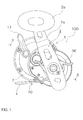
- Figure 1
- is a side view of a dual-bearing reel according to one embodiment of the present invention;
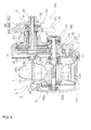
- Figure 2
- is a cross-sectional view of the section line II-II in
Figure 1 ; - Figure 3
- is an exploded perspective view showing the configuration of the
drag mechanism 23; - Figure 4
- is a partial enlarged view of the first and fourth brake plate assemblies according to one embodiment of the present invention;
- Figure 5
- is a partial enlarged view of the second and third brake plate assemblies according to one embodiment of the present invention;
- Figure 6A
- is a perspective view illustrating another embodiment in which the brake plate assembly comprises holes (Part 1: when there are holes in the thickness direction);
- Figure 6B
- is a cross-sectional view of the section line VIB-VIB in
Figure 6A ; - Figure 7A
- is a perspective view illustrating another embodiment in which the brake plate assembly comprises holes (Part 2: when there are holes in a direction that intersects with the thickness direction); and
- Figure 7B
- is a cross-sectional view of the section line VIIB-VIIB in
Figure 7A . - Meanwhile, in the explanation below, there are descriptions including wording indicating the left, right, front, and rear. In these descriptions, the direction in which the fishing line is unreeled (or cast) when the dual-
bearing reel 100 is mounted to the fishing rod corresponds to the front. Additionally, the left and right are defined by looking at the dual-bearing reel 100 from the rear in the above-described state. - As shown in
Figure 1 , thehandle 2 comprises a plate-like arm portion 2a and agrip 2b that is rotatably mounted to the distal end of thearm portion 2a. The proximal end of thearm portion 2a is integrally and rotatably mounted to the distal end of adrive shaft 30 mentioned below, as shown inFigure 2 . Specifically, the proximal end of thearm portion 2a is fastened to thedrive shaft 30 by anut 28. - The
reel body 1 comprises a frame 5, afirst side cover 6 and asecond side cover 7 that are mounted on both sides of the frame 5, as shown inFigure 2 . Aspool 12 is rotatably mounted inside thereel body 1 via aspool shaft 20. - The frame 5 comprises a left and right pair of a ring-shaped first side plate 8 and
second side plate 9, which are disposed at a prescribed interval, and a plurality of connectingportions 10 that couple the first side plate 8 and thesecond side plate 9. - The plurality of connecting
portions 10 are integrally formed with the first side plate 8 and thesecond side plate 9. A longitudinally long rod mountingleg portion 4 for mounting a reel to the fishing rod is riveted to the connecting portion 10 (refer toFigure 1 ). - The
first side cover 6 is integrally formed with the first side plate 8. Thefirst side cover 6 rotatably supports the left end of aspool shaft 20 mentioned below. Thesecond side cover 7 is fastened to amechanism mounting plate 34 by a plurality of screw members 11 (for example, five). Thesecond side cover 7 rotatably supports thedrive shaft 30. Aclutch lever 17 is mounted to thesecond side cover 7. Themechanism mounting plate 34 that forms the frame 5 is disposed between thesecond side cover 7 and thesecond side plate 9. - Meanwhile, the
clutch lever 17 is pivotally mounted to the rear portion of thesecond side cover 7. Theclutch lever 17 is coupled with aclutch control mechanism 22. When theclutch lever 17 pivots, a clutch mechanism 21 moves to a clutch-on and a clutch-off position via theclutch control mechanism 22. - As shown in
Figure 2 , arotation transmission mechanism 19, the clutch mechanism 21, theclutch control mechanism 22, adrag mechanism 23, and acasting control mechanism 24 are disposed between thesecond side cover 7 and themechanism mounting plate 34. - The
rotation transmission mechanism 19 transmits the rotation of thehandle 2 in the line winding direction to thespool 12. The details of therotation transmission mechanism 19 will be described below. - The clutch mechanism 21 couples and decouples the
handle 2 and thespool 12. When the clutch mechanism 21 is put in a clutch-off state (a decoupled state), thespool 12 is freely rotatable. - The
clutch control mechanism 22 is for controlling the clutch mechanism 21. - The
drag mechanism 23 brakes the rotation of thespool 12 in the casting direction. - The details of the
drag mechanism 23 will be described below. - A
casting control mechanism 24 adjusts the resistive force during the rotation of thespool 12. - As shown in
Figure 2 , thespool 12 comprises a left and right pair of plate-like flanges 12a on both sides, as well as a tubular line winding cylinder part 12b disposed between the pair offlanges 12a. Thespool 12 is non-rotatably fixed by, for example, serration bonding to aspool shaft 20 that extends through the inner peripheral side of the line winding cylinder part 12b. The fixing method is not limited to serration bonding, and various bonding methods can be used, such as key coupling, spline coupling, etc. - The
spool shaft 20 is disposed substantially parallel to thedrive shaft 30. Thespool shaft 20 extends through thesecond side plate 9 and extends to asecond boss portion 7f of thesecond side cover 7. Thespool shaft 20 is rotatably supported by thereel body 1 via a first axle bearing 26a and a second axle bearing 26b on both sides of thespool 12. - A
large diameter portion 20a is formed in the center of thespool shaft 20, and an engagement pin of the clutch mechanism 21 is fixed to thelarge diameter portion 20a. The engagement pin extends through thelarge diameter portion 20a in the radial direction, both ends of which protrude in the radial direction. - As shown in
Figure 2 andFigure 3 , therotation transmission mechanism 19 comprises adrive shaft 30, adrive gear 31 that is fixed to thedrive shaft 30, and atubular pinion gear 32 that meshes with thedrive gear 31. - The
drive shaft 30 is rotatably mounted to themechanism mounting plate 34 and thesecond side cover 7 via a third axle bearing 15 and a fourth axle bearing 16. As shown inFigure 3 , a plurality ofdetent portions 30a andflange portions 30d are formed on thedrive shaft 30. Specifically, notched surfaces that are parallel with each other are formed in the plurality ofdetent portions 30a. Theflange portion 30d is formed with a large diameter on the outer peripheral surface of thedrive shaft 30. - Additionally, a first male threaded
portion 30b and a second male threadedportion 30c are formed on thedrive shaft 30. Thearm portion 2a of thehandle 2 is fixed to the first male threadedportion 30b. A star drag 36 (discussed below) for adjusting the drag force of thedrag mechanism 23 is mounted on the second male threadedportion 30c. - In this embodiment, the
drive shaft 30 is prohibited from rotating in the casting direction (reverse rotation) by a roller-type first one-way clutch 86 (refer toFigure 2 ) and a pawl-type second one-way clutch 87 (refer toFigure 3 ). - As shown in
Figure 2 , the first one-way clutch 86 is mounted between thesecond side cover 7 and thedrive shaft 30. The first one-way clutch 86 comprises anouter ring 86a and aninner ring 86b. Theouter ring 86a is non-rotatably mounted to a first boss portion 7c. Theinner ring 86b is non-rotatably coupled with thedrive shaft 30. A rollingbody 86c is disposed between theouter ring 86a and theinner ring 86b. - As shown in
Figure 3 , the second one-way clutch 87 comprises aratchet wheel 88 and aratchet pawl 89. Theratchet wheel 88 is integrally and rotatably mounted to one of thedetent portions 30a of thedrive shaft 30. Theratchet wheel 88 is also disposed so as to come in contact with theflange portion 30d. That is, theratchet wheel 88 transmits the pressing force of thestar drag 36 to theflange portion 30d. - As shown in
Figure 2 , thedrive gear 31 is rotatably mounted to thedrive shaft 30. Thedrive gear 31 is frictionally coupled with thedrive shaft 30 via thedrag mechanism 23. Acircular housing recess 31a for housing thedrag mechanism 23 is formed on the side surface of the drive gear 31 (the right side surface inFigure 3 ). - A plurality of first engagement recesses 31b (for example, four) are formed on the inner peripheral surface of the
housing recess 31 a. A rotating member of a drag sounding mechanism, which is not diagrammed, integrally and rotatably engages with the plurality of first engagement recesses 31 b. Additionally, a second engagement recess 31 c is formed between two first engagement recesses 31 b. Here, a plurality of second engagement recesses 31 c (for example, two) is formed on the inner peripheral surface of thehousing recess 31 a so as to face each other. Locking lugs 55 and 56 of afriction mechanism 37 mentioned below integrally and rotatably engage with the plurality of second engagement recesses 31 c. - As shown in
Figure 2 , thepinion gear 32 is a tubular member. Aspool shaft 20 extends through thepinion gear 32. Thepinion gear 32 is movably mounted in the axial direction with respect to thespool shaft 20. - The left end of the
pinion gear 32 inFigure 2 is supported rotatably and movably in the axial direction with respect to themechanism mounting plate 34 and thesecond boss portion 7f via a fifth andsixth axle bearings pinion gear 32 being controlled by theclutch control mechanism 22. - The
drag mechanism 23 is actuated when the fishing line is pulled at a force that exceeds the drag force after adjustment. That is, thespool 12 is capable of rotating in the casting direction when thedrag mechanism 23 is actuated. As shown inFigure 1 to Figure 3 , thedrag mechanism 23 comprises a star drag 36 (one example of an adjustment member) and afriction mechanism 37, the drag force of which is adjusted by thestar drag 36. - The
star drag 36 is for adjusting the drag force. As shown inFigure 2 , thestar drag 36 adjusts the drag force of thefriction mechanism 37 via anadjustment mechanism 41 that changes the drag force of thefriction mechanism 37. For example, theadjustment mechanism 41 engages theinner ring 86b of the first one-way clutch 86. When thestar drag 36 is rotated, the pressing state of theadjustment mechanism 41 with respect to theinner ring 86b of the first one-way clutch 86 changes. Then, the drag force of thefriction mechanism 37 is adjusted in response to the pressing state of theadjustment mechanism 41. - The
friction mechanism 37 is capable of braking the rotation of the spool in the casting direction, and is disposed around thedrive shaft 30, as shown inFigure 2 andFigure 3 . Thefriction mechanism 37 is pressed by theadjustment mechanism 41 via the first one-way clutch 86 (e.g., byinner ring 86b). - As shown in
Figure 3 , thefriction mechanism 37 comprises a plurality ofbrake plate assemblies lining materials - The plurality of brake plate assemblies comprise a first
brake plate assembly 51, a secondbrake plate assembly 52, a thirdbrake plate assembly 53, and a fourthbrake plate assembly 54. The firstbrake plate assembly 51 engages thedetent portion 30a of thedrive shaft 30 and is integrally and rotatably coupled with thedrive shaft 30. The firstbrake plate assembly 51 is also integrally and rotatably coupled with respect to theinner ring 86b of the first one-way clutch 86. Additionally, theinner ring 86b of the first one-way clutch 86 abuts the firstbrake plate assembly 51, and theinner ring 86b presses the firstbrake plate assembly 51. Consequently, theinner ring 86b is integrally rotatable with respect to thedrive shaft 30, and the firstbrake plate assembly 51 is pressed by theinner ring 86b. - The second
brake plate assembly 52 and the fourthbrake plate assembly 54 are both integrally and rotatably coupled with thedrive gear 31. The secondbrake plate assembly 52 and the fourthbrake plate assembly 54 both have a pair of locking lugs 55 and 56 that are bent toward the left on the outer peripheral surface. These locking lugs 55 and 56 engage with the second engagement recesses 31 c of thedrive gear 31. Consequently, the secondbrake plate assembly 52 and the fourthbrake plate assembly 54 are integrally rotatable with thedrive gear 31. Additionally, the secondbrake plate assembly 52 and the fourthbrake plate assembly 54 are disposed so as to be relatively rotatable with respect to thedrive shaft 30. - The third
brake plate assembly 53 engages with thedetent portion 30a of thedrive shaft 30 and is integrally and rotatably coupled with thedrive shaft 30. - In this embodiment, the first one-way clutch 86 and the second one-way clutch 87 prohibit the
drive shaft 30 from rotating in the casting direction (reverse rotation). Accordingly, the firstbrake plate assembly 51 and the thirdbrake plate assembly 53, which are integrally and rotatably coupled with thedrive shaft 30, also do not rotate in the casting direction. On the other hand, the secondbrake plate assembly 52 is disposed so as to be integrally rotatable with thedrive gear 31 and to be relatively rotatable with respect to thedrive shaft 30. That is, when thedrive gear 31 is rotated, the secondbrake plate assembly 52 rotates relatively with respect to thedrive shaft 30, that is, to the firstbrake plate assembly 51 and the thirdbrake plate assembly 53. - The configuration of the first
brake plate assembly 51, the secondbrake plate assembly 52, the thirdbrake plate assembly 53, and the fourthbrake plate assembly 54 will be described in detail below. The firstbrake plate assembly 51, the secondbrake plate assembly 52, the thirdbrake plate assembly 53, and the fourthbrake plate assembly 54 is a clad material. - As shown in
Figure 4 , both the firstbrake plate assembly 51 and the fourthbrake plate assembly 54 are formed by a first plate element 61 (one example of a first brake plate and a fourth brake plate) and a second plate element 62 (one example of a second brake plate and a fifth brake plate). - The
first plate element 61 is formed by, for example, an aluminum alloy. Thefirst plate element 61 comprises afirst bonding surface 61a (one example of a first bonding surface and a fifth bonding surface). Theinner ring 86b of the first one-way clutch 86 abuts thefirst plate element 61, and thefirst plate element 61 is pressed by theinner ring 86b. - Additionally, the wear resistance of the
second plate element 62 is greater than that of thefirst plate element 61. Thesecond plate element 62 is formed by, for example, a stainless steel alloy. Thesecond plate element 62 comprises asecond bonding surface 62a (one example of a second bonding surface and a sixth bonding surface) and a firstfrictional contact surface 62b. Thesecond bonding surface 62a is bonded to thefirst bonding surface 61 a of thefirst plate element 61. - A first
frictional contact surface 62b of the firstbrake plate assembly 51 comes into frictional contact with afirst lining material 65a mentioned below. Meanwhile, the firstfrictional contact surface 62b of the fourthbrake plate assembly 54 comes into frictional contact with athird lining material 65c (one example for a first lining material and a third lining material) mentioned below. - To summarize the above, with the
first bonding surface 61 a of thefirst plate element 61 and thesecond bonding surface 62a of thesecond plate element 62 being bonded together, both the firstbrake plate assembly 51 and the fourthbrake plate assembly 54 function as standalone brake plates. - Additionally, in the first
brake plate assembly 51, which functions as a standalone brake plate, the second plate element 62 (the firstfrictional contact surface 62b) comes into frictional contact with thefirst lining material 65a. On the other hand, in the fourthbrake plate assembly 54, which functions as a standalone brake plate, the second plate element 62 (the firstfrictional contact surface 62b) comes into frictional contact with thethird lining material 65c. - Meanwhile, the locking
lug 56 of the fourthbrake plate assembly 54 is formed on both thefirst plate element 61 and thesecond plate element 62. - As shown in
Figure 5 , both the secondbrake plate assembly 52 and the thirdbrake plate assembly 53 are formed by a third plate element 71 (one example of a first brake plate and a sixth brake plate), a fourth plate element 72 (one example of a second brake plate and a seventh brake plate), and a fifth plate element 73 (one example of a third brake plate and an eighth brake plate). - The
third plate element 71 is formed by, for example, an aluminum alloy. Thethird plate element 71 comprises athird bonding surface 71 a (one example of a first bonding surface, a third bonding surface and a seventh bonding surface) and afourth bonding surface 71 b (one example of a third bonding surface, a fourth bonding surface and an eighth bonding surface). Thefourth bonding surface 71 b is disposed on the opposite side of thethird bonding surface 71 a. - The wear resistance of the
fourth plate element 72 is greater than that of thethird plate element 71. Thefourth plate element 72 is formed, for example, by a stainless steel alloy. Thefourth plate element 72 comprises afifth bonding surface 72a (one example of a second bonding surface and a ninth bonding surface) and a secondfrictional contact surface 72b. Thefifth bonding surface 72a is bonded to thethird bonding surface 71 a of thethird plate element 71. - The second
frictional contact surface 72b of the secondbrake plate assembly 52 comes into frictional contact with thefirst lining material 65a. Meanwhile, the secondfrictional contact surface 72b of the thirdbrake plate assembly 53 comes into frictional contact with asecond lining material 65b discussed below. - The wear resistance of the
fifth plate element 73 is greater than that of thethird plate element 71. Thefifth plate element 73 is formed, for example, by a stainless steel alloy. Thefifth plate element 73 comprises asixth bonding surface 73a (one example of a fourth bonding surface and a tenth bonding surface) and a thirdfrictional contact surface 73b. Thesixth bonding surface 73a is bonded to thefourth bonding surface 71 b of thethird plate element 71. - The third
frictional contact surface 73b of the secondbrake plate assembly 52 comes into frictional contact with thesecond lining material 65b. The thirdfrictional contact surface 73b of the thirdbrake plate assembly 53 comes into frictional contact with thethird lining material 65c. - To summarize the above, in both the second
brake plate assembly 52 and the thirdbrake plate assembly 53, thethird bonding surface 71 a of thethird plate element 71, and thefifth bonding surface 72a of thefourth plate element 72 are bonded together, and thefourth bonding surface 71 b of thethird plate element 71 and thesixth bonding surface 73a of thefifth plate element 73 are bonded together. That is, both the secondbrake plate assembly 52 and the thirdbrake plate assembly 53 function as standalone brake plates while thethird plate element 71 is disposed between thefourth plate element 72 and thefifth plate element 73. - Additionally, in the second
brake plate assembly 52, which functions as a standalone brake plate, the fourth plate element 72 (the secondfrictional contact surface 72b) comes into frictional contact with thefirst lining material 65a, and the fifth plate element 73 (the thirdfrictional contact surface 73b) comes into frictional contact with thesecond lining material 65b. Also, in the thirdbrake plate assembly 53, which functions as a standalone brake plate, the fourth plate element 72 (the secondfrictional contact surface 72b) comes into frictional contact with thesecond lining material 65b, and the fifth plate element 73 (the thirdfrictional contact surface 73b) comes into frictional contact with thethird lining material 65c. - Meanwhile, the locking
lug 55 of the secondbrake plate assembly 52 is formed on thethird plate element 71, thefourth plate element 72, and thefifth plate element 73. - Next, the configuration of the
first lining material 65a, thesecond lining material 65b, and thethird lining material 65c will be described in detail. - As shown in
Figure 3 to Figure 5 , thefirst lining material 65a is disposed between the firstbrake plate assembly 51 and the secondbrake plate assembly 52. One surface of thefirst lining material 65a comes into contact with the first brake plate assembly 51 (the firstfrictional contact surface 62b). The other surface of thefirst lining material 65a comes into contact with the second brake plate assembly 52 (the secondfrictional contact surface 72b). - The
second lining material 65b is disposed between the secondbrake plate assembly 52 and the thirdbrake plate assembly 53. One surface of thesecond lining material 65b comes into contact with the second brake plate assembly 52 (the thirdfrictional contact surface 73b). The other surface of thesecond lining material 65b also comes into contact with the third brake plate assembly 53 (the secondfrictional contact surface 72b). - The
third lining material 65c is disposed between the thirdbrake plate assembly 53 and the fourthbrake plate assembly 54. One surface of thethird lining material 65c comes into contact with the third brake plate assembly 53 (the thirdfrictional contact surface 73b). The other surface of thethird lining material 65c comes into contact with the fourth brake plate assembly 54 (the firstfrictional contact surface 62b). - The
first lining material 65a, thesecond lining material 65b, and thethird lining material 65c is configured by, for example, a metal-based sintered material. Additionally, plate materials that come in frictional contact with each of these first tothird lining materials - In this embodiment, the above-described
ratchet wheel 88 is disposed to be adjacent to thedrive gear 31 and rotates relatively. For this reason, afourth lining material 65d is disposed between theratchet wheel 88 and thedrive gear 31. Thisfourth lining material 65d also contributes to the generation of drag force. - The
fourth lining material 65d is configured by, for example, carbon or felt. Here, an example was shown in which the fourth lining material is formed by, for example, carbon or felt, but the fourth lining material can also be formed by, for example, a metal-based sintered material. - The embodiment described above can be expressed as the following.
- (A) The first
brake plate assembly 51 and the fourthbrake plate assembly 54 of the present dual-bearing reel 100 comprises afirst plate element 61 and asecond plate element 62. Thefirst plate element 61 comprises afirst bonding surface 61 a. Thesecond plate element 62 comprises asecond bonding surface 62a. Thesecond bonding surface 62a is bonded to thefirst bonding surface 61 a of thefirst plate element 61. The wear resistance of thesecond plate element 62 is greater than that of thefirst plate element 61. - In the first
brake plate assembly 51 and the fourthbrake plate assembly 54, thefirst bonding surface 61 a of thefirst plate element 61 and thesecond bonding surface 62a of the second plate element are bonded together. That is, both the firstbrake plate assembly 51 and the fourthbrake plate assembly 54 function as standalone brake plates. Additionally, since the wear resistance of thesecond plate element 62 is greater than that of thefirst plate element 61, thefirst lining material 65a and thethird lining material 65c come in frictional contact with thesecond plate element 62. - That is, in the first
brake plate assembly 51 and the fourthbrake plate assembly 54, the portion that comes into frictional contact with thefirst lining material 65a and thethird lining material 65c is formed by thesecond plate element 62, and the portion that does not come into frictional contact with thefirst lining material 65a and thethird lining material 65c is formed by thefirst plate element 61. Accordingly, the drag force can be enhanced by thesecond plate element 62, and the weight can be reduced by thefirst plate element 61. That is, it is possible to provide the firstbrake plate assembly 51 and the fourthbrake plate assembly 54 such that they are able to simultaneously enhance the drag force and reduce the weight. - Additionally, the second
brake plate assembly 52 and the thirdbrake plate assembly 53 of the present dual-bearing reel 100 comprises thethird plate element 71, thefourth plate element 72, and thefifth plate element 73. Thethird plate element 71 corresponds to thefirst plate element 61 of the firstbrake plate assembly 51 and the fourthbrake plate assembly 54. Thefourth plate element 72 and thefifth plate element 73 correspond to thesecond plate element 62 of the firstbrake plate assembly 51 and the fourthbrake plate assembly 54. Therefore, the secondbrake plate assembly 52 and the thirdbrake plate assembly 53 are able to obtain the same effects as the firstbrake plate assembly 51 and the fourthbrake plate assembly 54. - (B) In the first to the fourth
brake plate assemblies bearing reel 100, thefirst plate element 61 and thethird plate element 71 are formed by an aluminum alloy. - In this embodiment, since the
first plate element 61 and thethird plate element 71 are formed by an aluminum alloy, it is possible to reduce the weight of the first to the fourthbrake plate assemblies - (C) In the first to the fourth
brake plate assemblies bearing reel 100, thesecond plate element 62, thefourth plate element 72, and thefifth plate element 73 are formed by a stainless steel alloy. - In this embodiment, since the
second plate element 62, thefourth plate element 72, and thefifth plate element 73 are formed by a stainless steel alloy, it is possible to enhance the wear resistance of the first to the fourthbrake plate assemblies - (D) The second
brake plate assembly 52 and the thirdbrake plate assembly 53 of the present dual-bearing reel 100 comprises afourth plate element 72 and afifth plate element 73. The wear resistance of thefourth plate element 72 and thefifth plate element 73 is greater than that of thethird plate element 71. - Accordingly, the
fourth plate element 72 comprises afifth bonding surface 72a, and thefifth plate element 73 comprises asixth bonding surface 73a. Thefifth bonding surface 72a is bonded to thethird bonding surface 71 a of thethird plate element 71. Thesixth bonding surface 73a is bonded to thefourth bonding surface 71 b of thethird plate element 71. That is, both the secondbrake plate assembly 52 and the thirdbrake plate assembly 53 function as standalone brake plates in a state in which thethird plate element 71 is disposed between thefourth plate element 72 and thefifth plate element 73, and they are bonded together. - Additionally, in this embodiment, the wear resistance of the
fourth plate element 72 and thefifth plate element 73 is greater than that of thethird plate element 71. Accordingly, thefirst lining material 65a comes into frictional contact with thefourth plate element 72 of the secondbrake plate assembly 52. Thesecond lining material 65b comes into frictional contact with thefifth plate element 73 of the secondbrake plate assembly 52. On the other hand, thesecond lining material 65b comes into frictional contact with thefourth plate element 72 of the thirdbrake plate assembly 53. Thethird lining material 65c comes into frictional contact with thefifth plate element 73 of the thirdbrake plate assembly 53. - Accordingly, the drag force can be enhanced by the
fourth plate element 72 and thefifth plate element 73, and the weight can be reduced by thethird plate element 71. That is, it is possible to provide the secondbrake plate assembly 52 and the thirdbrake plate assembly 53 such that they are able to simultaneously enhance the drag force and reduce the weight. - (E) The present dual-
bearing reel 100 comprises areel body 1, aspool 12, and adrag mechanism 23. Thespool 12 is rotatably mounted to thereel body 1. Thedrag mechanism 23 comprises afriction mechanism 37. Thefriction mechanism 37 is able to brake the rotation of thespool 12 in the casting direction, and comprises first to fourthbrake plate assemblies third lining materials - In the present dual-
bearing reel 100, thefriction mechanism 37 of thedrag mechanism 23 is able to brake the rotation of thespool 12 in the casting direction. In this embodiment, since thefriction mechanism 37 comprises first to fourthbrake plate assemblies third lining materials - (F) The present dual-
bearing reel 100 comprises areel body 1, aspool 12, and adrag mechanism 23. Thespool 12 is rotatably mounted to thereel body 1. Thedrag mechanism 23 comprises afriction mechanism 37. Thefriction mechanism 37 is able to brake the rotation of thespool 12 in the casting direction. Thefriction mechanism 37 comprises first to fourthbrake plate assemblies third lining materials - The first
brake plate assembly 51 and the fourthbrake plate assembly 54 comprise afirst plate element 61 and asecond plate element 62. Thefirst plate element 61 comprises afirst bonding surface 61 a. - The wear resistance of the
second plate element 62 is greater than that of thefirst plate element 61. Thesecond plate element 62 comprises asecond bonding surface 62a and a firstfrictional contact surface 62b. Thesecond bonding surface 62a is bonded to thefirst bonding surface 61 a of thefirst plate element 61. Accordingly, the firstfrictional contact surface 62b of the firstbrake plate assembly 51 comes into frictional contact with thefirst lining material 65a. On the other hand, the firstfrictional contact surface 62b of the fourthbrake plate assembly 54 comes into frictional contact with thethird lining material 65c. - Both the second
brake plate assembly 52 and the thirdbrake plate assembly 53 comprise athird plate element 71, afourth plate element 72, and afifth plate element 73. - The
third plate element 71 comprises athird bonding surface 71 a and afourth bonding surface 71 b. Thefourth bonding surface 71b is provided on the opposite side of thethird bonding surface 71 a. - The wear resistance of the
fourth plate element 72 is greater than that of thethird plate element 71. Thefourth plate element 72 comprises afifth bonding surface 72a and a secondfrictional contact surface 72b. Thefifth bonding surface 72a is bonded to thethird bonding surface 71 a of thethird plate element 71. Here, the secondfrictional contact surface 72b of the secondbrake plate assembly 52 comes into frictional contact with thefirst lining material 65a. On the other hand, the secondfrictional contact surface 72b of the thirdbrake plate assembly 53 comes into frictional contact with thesecond lining material 65b. - The wear resistance of the
fifth plate element 73 is greater than that of thethird plate element 71. Thefifth plate element 73 comprises asixth bonding surface 73a and a thirdfrictional contact surface 73b. Thesixth bonding surface 73a is bonded to thefourth bonding surface 71 b of thethird plate element 71. Here, the thirdfrictional contact surface 73b of the secondbrake plate assembly 52 comes into frictional contact with thesecond lining material 65b. The thirdfrictional contact surface 73b of the thirdbrake plate assembly 53 comes into frictional contact with thethird lining material 65c. - In the present dual-
bearing reel 100, the firstbrake plate assembly 51 and the fourthbrake plate assembly 54 function as standalone brake plates in a state in which thefirst plate element 61 and thesecond plate element 62 are bonded together. Additionally, the firstbrake plate assembly 51 comes into frictional contact with thefirst lining material 65a. On the other hand, the fourthbrake plate assembly 54 comes into frictional contact with thethird lining material 65c. - In the second
brake plate assembly 52 and the thirdbrake plate assembly 53, both the secondbrake plate assembly 52 and the thirdbrake plate assembly 53 function as standalone brake plates in a state in which thethird plate element 71 is disposed between thefourth plate element 72 and thefifth plate element 73 and they are bonded together. Additionally, the secondbrake plate assembly 52 comes into frictional contact with thefirst lining material 65a and thesecond lining material 65b. The thirdbrake plate assembly 53 also comes into frictional contact with thesecond lining material 65b and thethird lining material 65c. - Accordingly, in the
present fishing reel 100, it is possible to reduce the weight of the brake plate assembly with thefirst plate element 61 of the first and the fourthbrake plate assemblies third plate element 71 of the second and the thirdbrake plate assemblies second plate element 62 of the first and fourthbrake plate assemblies fifth plate elements brake plate assemblies bearing reel 100 that is able to simultaneously enhance the drag force and reduce the weight. - (G) In the present dual-
bearing reel 100, the first to thethird lining materials - In this embodiment, since the first to the
third lining materials third lining materials brake plate assemblies - (H) In the present dual-
bearing reel 100, thedrag mechanism 23 further comprises astar drag 36 for adjusting the firstbrake plate assembly 51. - In this embodiment, the first
brake plate assembly 51 is adjusted by thestar drag 36. Then, the pressure state of the first to the fourthbrake plate assemblies third lining materials brake plate assemblies third lining materials brake plate assembly 51 is adjusted by thestar drag 36, the frictional force in thefriction mechanism 37 changes. Accordingly, in the present dual-bearing reel 100, it is possible to reliably change the frictional force in thefriction mechanism 37 with thestar drag 36. - One embodiment of the present invention is described above, but the present invention is not limited to the above-described embodiment; various modifications can be made without departing from the scope of the invention. In particular, the various embodiments and modified examples described in the present Specification can be freely combined according to necessity.
- (a) In the above-described embodiment, an example is provided in which the first to fourth
brake plate assemblies drag mechanism 23 of the dual-bearing reel 100; however, the first to fourthbrake plate assemblies - (b) In the first to fourth
brake plate assemblies fifth plate elements hole 90, 91 (one example of a first hole and/or a second hole). - For example, as shown in
Figure 6A, Figure 6B ,Figure 7A, and Figure 7B , the secondbrake plate assembly 52 can compriseholes brake plate assembly 52 has been enlarged inFigure 6A andFigure 7A in order to facilitate the description. - As shown in
Figure 6A and Figure 6B , in the secondbrake plate assembly 52, theholes 90 can extend in the thickness direction of the third to thefifth plate elements holes 90 in this way. - Meanwhile, while not illustrated, at least one hole can be formed in one or two of the third to the
fifth plate elements holes 90 are formed at intervals at prescribed angles in the peripheral direction; however, the angle at which theholes 90 are formed can be any angle. - Also, as shown in
Figure 7A and Figure 7B , in the secondbrake plate assembly 52, holes 91 can extend in a direction that intersects with the thickness direction of thethird plate element 71. Maintaining the bonding area of thebonding surfaces brake plate assembly 52 is possible by forming theholes 91 in this way. Consequently, it is possible to effectively reduce the weight while maintaining the joining strength. - Meanwhile, as described herein, an example is provided in which the
holes 91 are formed at intervals at prescribed angles in the peripheral direction, but the angle at which theholes 91 are formed can be any angle. Meanwhile, while not illustrated, the above-describedholes 91 can be formed in two or all of the third to thefifth plate elements - Meanwhile, in
Figure 6A, Figure 6B ,Figure 7A, and Figure 7B , theholes brake plate assembly 52, but thesame holes brake plate assembly 51, the thirdbrake plate assembly 53, and the fourthbrake plate assembly 54. - With the above-described configuration, it is possible to effectively reduce the weight of the first to the fourth
brake plate assemblies - (c) In the second
brake plate assembly 52 of the above-described embodiment, as shown inFigure 6B , the thickness t1 of thefifth plate element 73 can be configured to be thicker than the thickness t2 of thefourth plate element 72. Also, while not illustrated, it is possible to configure the thickness t1 of thefifth plate element 73 to be thicker than the thickness t2 of thefourth plate element 72 in the same way as with the secondbrake plate assembly 52 in the thirdbrake plate assembly 53. - Consequently, it is possible to configure the
lining material 65b (65c) on thefifth plate element 73 side from a material with a greater frictional force or a material with a different characteristic than thelining material 65a (65b) on thefourth plate element 72 side. Accordingly, since the width of the selection of lining material can be widened, the adjustment range of the drag performance (the friction performance) can be expanded. - Meanwhile, in
Figure 6B , an example is provided in which the thickness t1 of thefifth plate element 73 is thicker than the thickness t2 of thefourth plate element 72; however, the configuration can be such that the thickness of thefourth plate element 72 is thicker than the thickness of thefifth plate element 73. In this embodiment as well, it is possible to expand the adjustment range of the drag performance (the friction performance). - (d) In both the second
brake plate assembly 52 and the thirdbrake plate assembly 53 of the embodiment described above, the wear resistance of the fourth plate element 72 (or the fifth plate element 73) can be greater than that of the fifth plate element 73 (or the fourth plate element 72). - In this embodiment, it is possible to configure the
lining materials lining materials materials lining materials -
- 1
- reel body
- 2
- handle
- 2a
- arm portion
- 2b
- grip
- 4
- leg portion
- 5
- frame
- 6
- first side cover
- 7
- second side cover
- 7c
- first boss portion
- 7f
- second boss portion
- 8
- first side plate
- 9
- second side plate
- 10
- connecting portion
- 11
- screw members
- 12
- spool
- 12a
- plate like flange
- 12b
- tubular line winding cylinder part
- 15
- third axle bearing
- 16
- fourth axle bearing
- 17
- clutch lever
- 18a
- fifth axle bearing
- 18b
- sixth axle bearing
- 19
- rotation transmission mechanism
- 20
- spool shaft
- 20a
- large diameter portion
- 21
- clutch mechanism
- 22
- clutch control mechanism
- 23
- drag mechanism
- 24
- casting control mechanism
- 26a
- first axle bearing
- 26b
- second axle bearing
- 28
- nut
- 29
- engagement pin
- 30
- drive shaft
- 30a
- detent portion
- 30b
- first male thread portion
- 30c
- second male thread portion
- 30d
- flange portion
- 31
- drive gear
- 31a
- circular housing recess
- 31b
- first engagement recess
- 31c
- second engagement recess
- 32
- pinon gear
- 34
- mechanism mounting plate
- 36
- star drag/ adjusting member
- 37
- friction meachanism
- 41
- adjustment mechanism
- 51
- first brake plate assembly
- 52
- second brake plate assembly
- 53
- third brake plate assembly
- 54
- fourth brake plate assembly
- 55
- locking lug
- 56
- locking lug
- 61
- first plate element (first brake plate, fourth brake plate)
- 61a
- first bonding surface (fifth bonding surface)
- 62
- second plate element (second brake plate, fifth brake plate)
- 62a
- second bonding surface (sixth bonding surface)
- 62b
- first frictional contact surface
- 65a
- first lining material
- 65b
- second lining material
- 65c
- third lining material
- 65d
- fourth lining material
- 71
- third plate element (first brake plate, sixth brake plate)
- 71a
- third bonding surface (first bonding surface, seventh bonding surface)
- 71b
- fourth bonding surface (third bonding surface, eighth bonding surface)
- 72
- fourth plate element (second brake plate, seventh brake plate)
- 72a
- fifth bonding surface (second bonding surface, ninth bonding surface)
- 72b
- second frictional contact surface
- 73
- fifth plate element (third brake plate, eighth brake plate)
- 73a
- sixth bonding surface (fourth bonding surface, tenth bonding surface)
- 73b
- third frictional contact surface
- 86
- first one- way clutch
- 86a
- outer ring
- 86b
- inner ring
- 86c
- rolling body
- 87
- second one- way clutch
- 88
- ratchet wheel
- 89
- ratchet pawl
- 90
- hole
- 91
- hole
- 100
- reel
- t1
- thickness of fifth plate element
- t2
- thickness of fourth plate element
Claims (18)
- A brake plate assembly (51, 52, 53, 54) in a drag mechanism (23) of a fishing reel (100), comprising:a first brake plate (61, 71) having a first bonding surface (71 a, 61 a); anda second brake plate (62, 72) having a second bonding surface (62a, 72a) bonded to the first bonding surface (71 a, 61 a), andhaving greater wear resistance than that of the first brake plate (61, 71).
- The brake plate assembly (51, 52, 53, 54) for the drag mechanism (23) of the fishing reel (100) recited in claim 1, wherein the first brake plate (61, 71) is an aluminum alloy.
- The brake plate assembly (51, 52, 53, 54) for the drag mechanism (23) of the fishing reel (100) recited in claim 1 or 2, wherein the second brake plate (62, 72) is a stainless steel alloy.
- The brake plate assembly (52, 53) for the drag mechanism (23) of the fishing reel (100) recited in claims 1 to 3, wherein at least one of the first brake plate (71) and the second brake plate (72) includes at least one first hole (90, 91).
- The brake plate assembly (52, 53) for the drag mechanism (23) of the fishing reel (100) recited in claim 4, wherein the first hole (90) extends in a thickness direction of at least one of the first brake plate (71) and the second brake plate (72).
- The brake plate assembly (52, 53) for the drag mechanism (23) of the fishing reel (100) recited in claim 4 or 5, wherein the first hole (90, 91) extends in a direction that intersects with a thickness direction of at least one of the first brake plate (71) and the second brake plate (72).
- The brake plate assembly (52, 53) for the drag mechanism (23) of the fishing reel recited in claims 1 to 6, further comprising a third brake plate (73) having a greater wear resistance than that of the first brake plate (71), the first brake plate (71) including a third bonding surface (71 b) disposed on the opposite side of the first bonding surface (71 a), and the third brake plate (73) including a fourth bonding surface (73a) bonded to the third bonding surface (71 b).
- The brake plate assembly (52, 53) for the drag mechanism (23) of the fishing reel (100) recited in claim 7, wherein the third brake plate (73) is a stainless steel alloy.
- The brake plate assembly (52, 53) for the drag mechanism (23) of the fishing reel (23) recited in claim 7 or 8, wherein the wear resistance of the third brake plate (73) is greater than that of the second brake plate (72).
- The brake plate assembly (52, 53) for the drag mechanism (23) of the fishing reel (100) recited in claims 7 to 9, wherein the thickness (t1) of the third brake plate (73) is greater than the thickness (t1) of the second brake plate (72).
- The brake plate assembly (52, 53) for the drag mechanism (23) of the fishing reel (100) recited in claims 7 to 10, wherein the third brake plate (73) includes at least one second hole (90).
- The brake plate (52, 53) assembly for the drag mechanism (23) of the fishing reel (100) recited in claim 11, wherein the second hole (90) extends in the thickness direction of the third brake plate (73).
- The brake plate assembly (52) for the drag mechanism (23) of the fishing reel (100) recited in claim 11 or 12, wherein the second hole (90) extends in a direction that intersects with the thickness direction.
- A fishing reel (100), comprising: a reel body (1); a spool (12) rotatably mounted to the reel body (1); and a drag mechanism (23) having a braking structure configured to brake the rotation of the spool (12) in a casting direction, the braking structure including a lining material (65a, 65b, 65c, 65d) and the brake plate assembly (51, 52, 53, 54) for the drag mechanism (23) of the fishing reel (100) recited in claims 1 to 13.
- The fishing reel (100) recited in claim 14, wherein the lining material (65a, 65b, 65c, 65d) is a metal-based sintered material.
- A fishing reel (100), comprising:a reel body (1); a spool (12) rotatably mounted to the reel body (1); anda drag mechanism (23) having a braking structure configured to brake the rotation of the spool (12) in a casting direction, the braking structure including a first lining material (65a, 65c), a second lining material (65b),a first brake plate assembly (51, 54), anda second brake plate assembly (52),the first brake plate assembly (51, 54) including a fourth brake plate (61) having a fifth bonding surface (61 a), anda fifth brake plate (62) having a first frictional contact surface (62b) configured to frictionally contact a sixth bonding surface (62a) bonded to the fifth bonding surface (61 a) andthe fifth brake plate (62) having a greater wear resistance than that of the fourth brake plate (61), andthe second brake plate assembly (52, 53) including a sixth brake plate (71) having a seventh bonding surface (71a) and an eighth bonding surface (71 b) disposed on an opposite side of the seventh bonding surface (71 a),a seventh brake plate (72) having a second frictional contact surface (72b) configured to frictionally contact a ninth bonding surface (72a) bonded to the seventh bonding surface (71a) andan eighth brake plate (73) having a third frictional contact surface (73b) configured to frictionally contact a tenth bonding surface (73a) bonded to the eighth bonding surface (71 b) and the second lining material (65b) having a greater wear resistance than that of the sixth brake plate (72), and the eighth brake plate (73) having a greater wear resistance than that of the sixth brake plate (72),.
- The fishing reel (100) recited in claim 16, wherein the first lining material (65a) and the second lining material (65b) are a metal-based sintered material.
- The fishing reel (100) recited in claim 16 or 17, wherein the drag mechanism (23) includes an adjustment member (36) configured to adjust the first brake plate assembly (51).
Applications Claiming Priority (1)
| Application Number | Priority Date | Filing Date | Title |
|---|---|---|---|
| JP2014092498A JP6368529B2 (en) | 2014-04-28 | 2014-04-28 | Brake plate assembly for fishing reel drag mechanism, and fishing reel provided with brake plate assembly for fishing reel drag mechanism |
Publications (2)
| Publication Number | Publication Date |
|---|---|
| EP2939536A1 true EP2939536A1 (en) | 2015-11-04 |
| EP2939536B1 EP2939536B1 (en) | 2018-05-30 |
Family
ID=52779554
Family Applications (1)
| Application Number | Title | Priority Date | Filing Date |
|---|---|---|---|
| EP15161363.5A Active EP2939536B1 (en) | 2014-04-28 | 2015-03-27 | Brake plate assembly for a drag mechanism of a fishing reel |
Country Status (7)
| Country | Link |
|---|---|
| US (1) | US9832984B2 (en) |
| EP (1) | EP2939536B1 (en) |
| JP (1) | JP6368529B2 (en) |
| KR (1) | KR102392179B1 (en) |
| CN (1) | CN105028359B (en) |
| MY (1) | MY172335A (en) |
| TW (1) | TWI650072B (en) |
Cited By (1)
| Publication number | Priority date | Publication date | Assignee | Title |
|---|---|---|---|---|
| EP3342285A1 (en) * | 2017-01-03 | 2018-07-04 | Okuma Fishing Tackle Co., Ltd. | Brake mechanism of fishing reel |
Families Citing this family (7)
| Publication number | Priority date | Publication date | Assignee | Title |
|---|---|---|---|---|
| US10091978B2 (en) * | 2015-04-02 | 2018-10-09 | Mark E. Champion | Lever-operated fishing reel |
| JP6879844B2 (en) * | 2017-06-30 | 2021-06-02 | 帝人株式会社 | Fishing gear member and fishing reel drag device using it |
| CN109315363B (en) * | 2018-09-20 | 2023-08-29 | 宁波海宝渔具有限公司 | Brake mechanism and fishing gear using same |
| US11785930B2 (en) | 2020-09-14 | 2023-10-17 | TrikaUSA Inc. | Fishing reel with translatable spool |
| US12102073B2 (en) * | 2021-06-14 | 2024-10-01 | James Edwards Milton | Fishing reel with a line transfer mechanism |
| US11974558B2 (en) * | 2021-12-21 | 2024-05-07 | Accurate Grinding and Mfg. Corp. | Star drag fishing reel |
| JP7854367B2 (en) * | 2022-08-10 | 2026-05-01 | 株式会社シマノ | Fishing reel |
Citations (7)
| Publication number | Priority date | Publication date | Assignee | Title |
|---|---|---|---|---|
| US5040743A (en) * | 1990-04-16 | 1991-08-20 | Zebco Corporation | Spinning reel with rear-actuated front drag |
| US20020027176A1 (en) * | 2000-08-22 | 2002-03-07 | Takeshi Ikuta | Dual-bearing reel spool-locking mechanism |
| JP2002218880A (en) | 2001-01-23 | 2002-08-06 | Daiwa Seiko Inc | Fishing reel |
| JP2002238421A (en) | 2001-02-16 | 2002-08-27 | Daiwa Seiko Inc | Lining material for fishing reel and method of manufacturing the same |
| JP2003000114A (en) | 2001-06-26 | 2003-01-07 | Daiwa Seiko Inc | Fishing reel |
| US7017845B2 (en) * | 2004-05-28 | 2006-03-28 | Penn Fishing Tackel Manufacturing Co. | Drag material and apparatus for fishing reels |
| US20130292504A1 (en) * | 2012-05-04 | 2013-11-07 | Doyo Engineering Co., Ltd. | Fishing reel having centrifugal brake system |
Family Cites Families (11)
| Publication number | Priority date | Publication date | Assignee | Title |
|---|---|---|---|---|
| US3428268A (en) * | 1966-07-07 | 1969-02-18 | Oscar Fleischer | Brake for fishing reel |
| JPS5931638A (en) * | 1982-08-13 | 1984-02-20 | ダイワ精工株式会社 | Drag mechanism of fishing reel |
| JPS60185479U (en) * | 1984-05-18 | 1985-12-09 | 株式会社シマノ | Lining material for fishing reels |
| JP2687150B2 (en) * | 1988-10-22 | 1997-12-08 | スズキ株式会社 | Disc brake rotor manufacturing method |
| JP3525054B2 (en) * | 1998-06-26 | 2004-05-10 | ダイワ精工株式会社 | Fishing reel |
| JP3747429B2 (en) * | 1999-07-07 | 2006-02-22 | 株式会社シマノ | Double bearing reel braking device |
| TW462871B (en) * | 1999-12-03 | 2001-11-11 | Shimano Kk | Spinning reel spool |
| TW200809113A (en) * | 2006-08-11 | 2008-02-16 | Metal Ind Res & Dev Ct | Structure of braking disc having a composition |
| US7665683B2 (en) * | 2007-12-18 | 2010-02-23 | Shimano Inc. | Fishing line guiding mechanism of spinning reel |
| TWM423441U (en) * | 2011-11-09 | 2012-03-01 | Shih-Yuan Yeh | Brake structure for fishing reel |
| JP6072422B2 (en) * | 2012-03-12 | 2017-02-01 | 株式会社シマノ | Double bearing reel |
-
2014
- 2014-04-28 JP JP2014092498A patent/JP6368529B2/en active Active
- 2014-12-03 KR KR1020140171963A patent/KR102392179B1/en active Active
- 2014-12-26 TW TW103145864A patent/TWI650072B/en not_active IP Right Cessation
-
2015
- 2015-02-12 US US14/620,485 patent/US9832984B2/en active Active
- 2015-03-20 MY MYPI2015700897A patent/MY172335A/en unknown
- 2015-03-27 EP EP15161363.5A patent/EP2939536B1/en active Active
- 2015-04-28 CN CN201510208407.8A patent/CN105028359B/en not_active Expired - Fee Related
Patent Citations (7)
| Publication number | Priority date | Publication date | Assignee | Title |
|---|---|---|---|---|
| US5040743A (en) * | 1990-04-16 | 1991-08-20 | Zebco Corporation | Spinning reel with rear-actuated front drag |
| US20020027176A1 (en) * | 2000-08-22 | 2002-03-07 | Takeshi Ikuta | Dual-bearing reel spool-locking mechanism |
| JP2002218880A (en) | 2001-01-23 | 2002-08-06 | Daiwa Seiko Inc | Fishing reel |
| JP2002238421A (en) | 2001-02-16 | 2002-08-27 | Daiwa Seiko Inc | Lining material for fishing reel and method of manufacturing the same |
| JP2003000114A (en) | 2001-06-26 | 2003-01-07 | Daiwa Seiko Inc | Fishing reel |
| US7017845B2 (en) * | 2004-05-28 | 2006-03-28 | Penn Fishing Tackel Manufacturing Co. | Drag material and apparatus for fishing reels |
| US20130292504A1 (en) * | 2012-05-04 | 2013-11-07 | Doyo Engineering Co., Ltd. | Fishing reel having centrifugal brake system |
Cited By (1)
| Publication number | Priority date | Publication date | Assignee | Title |
|---|---|---|---|---|
| EP3342285A1 (en) * | 2017-01-03 | 2018-07-04 | Okuma Fishing Tackle Co., Ltd. | Brake mechanism of fishing reel |
Also Published As
| Publication number | Publication date |
|---|---|
| TWI650072B (en) | 2019-02-11 |
| KR102392179B1 (en) | 2022-04-29 |
| JP2015208284A (en) | 2015-11-24 |
| JP6368529B2 (en) | 2018-08-01 |
| MY172335A (en) | 2019-11-21 |
| US9832984B2 (en) | 2017-12-05 |
| KR20150124365A (en) | 2015-11-05 |
| CN105028359A (en) | 2015-11-11 |
| US20150305315A1 (en) | 2015-10-29 |
| TW201540182A (en) | 2015-11-01 |
| CN105028359B (en) | 2019-10-15 |
| EP2939536B1 (en) | 2018-05-30 |
Similar Documents
| Publication | Publication Date | Title |
|---|---|---|
| EP2939536B1 (en) | Brake plate assembly for a drag mechanism of a fishing reel | |
| JP2015208284A5 (en) | ||
| TWI566694B (en) | One-way clutch for fishing reel | |
| JP5324819B2 (en) | Lever drag reel reverse rotation prevention mechanism | |
| US7866587B2 (en) | Drag adjusting mechanism for dual-bearing reel | |
| JP5701788B2 (en) | Gears built into fishing reels | |
| US9615560B2 (en) | Dual-bearing reel | |
| TWI465193B (en) | Reel shaft support structure of double bearing reel | |
| JP2009273378A5 (en) | ||
| US9700032B2 (en) | Clutch return mechanism for a dual-bearing reel | |
| KR20150077323A (en) | Dual-bearing reel pinion gear and dual-bearing reel | |
| CN103907577A (en) | Dual-bearing reel | |
| JP2015228799A5 (en) | ||
| TWI772580B (en) | Dual-bearing reel | |
| JP3185765U (en) | Double-bearing reel drive shaft | |
| US10045519B2 (en) | Washer for fishing reel | |
| KR102502468B1 (en) | Dual-bearing fishing reel | |
| JP5931495B2 (en) | Double bearing type reel | |
| JP3882019B2 (en) | Fishing reel drag mechanism | |
| JP3961690B2 (en) | Double-bearing reel drag mechanism | |
| JP2933301B2 (en) | Drag adjuster for fishing reel | |
| JP2013192507A (en) | Double-bearing type reel for fishing | |
| US9560841B2 (en) | Spinning reel for fishing and a braking operation lever for the rotor braking device | |
| JP2010148458A (en) | Spinning reel | |
| JP2005261207A (en) | Left and right-winding direction-switching mechanism of single axial bearing reel |
Legal Events
| Date | Code | Title | Description |
|---|---|---|---|
| PUAI | Public reference made under article 153(3) epc to a published international application that has entered the european phase |
Free format text: ORIGINAL CODE: 0009012 |
|
| AK | Designated contracting states |
Kind code of ref document: A1 Designated state(s): AL AT BE BG CH CY CZ DE DK EE ES FI FR GB GR HR HU IE IS IT LI LT LU LV MC MK MT NL NO PL PT RO RS SE SI SK SM TR |
|
| AX | Request for extension of the european patent |
Extension state: BA ME |
|
| 17P | Request for examination filed |
Effective date: 20160503 |
|
| RBV | Designated contracting states (corrected) |
Designated state(s): AL AT BE BG CH CY CZ DE DK EE ES FI FR GB GR HR HU IE IS IT LI LT LU LV MC MK MT NL NO PL PT RO RS SE SI SK SM TR |
|
| STAA | Information on the status of an ep patent application or granted ep patent |
Free format text: STATUS: EXAMINATION IS IN PROGRESS |
|
| 17Q | First examination report despatched |
Effective date: 20170321 |
|
| GRAP | Despatch of communication of intention to grant a patent |
Free format text: ORIGINAL CODE: EPIDOSNIGR1 |
|
| STAA | Information on the status of an ep patent application or granted ep patent |
Free format text: STATUS: GRANT OF PATENT IS INTENDED |
|
| INTG | Intention to grant announced |
Effective date: 20171222 |
|
| RIN1 | Information on inventor provided before grant (corrected) |
Inventor name: IWAI, TORU Inventor name: SOUWA, MAKOTO Inventor name: KASHIMOTO, YOSHIKAZU |
|
| GRAS | Grant fee paid |
Free format text: ORIGINAL CODE: EPIDOSNIGR3 |
|
| GRAA | (expected) grant |
Free format text: ORIGINAL CODE: 0009210 |
|
| STAA | Information on the status of an ep patent application or granted ep patent |
Free format text: STATUS: THE PATENT HAS BEEN GRANTED |
|
| AK | Designated contracting states |
Kind code of ref document: B1 Designated state(s): AL AT BE BG CH CY CZ DE DK EE ES FI FR GB GR HR HU IE IS IT LI LT LU LV MC MK MT NL NO PL PT RO RS SE SI SK SM TR |
|
| REG | Reference to a national code |
Ref country code: GB Ref legal event code: FG4D |
|
| REG | Reference to a national code |
Ref country code: CH Ref legal event code: EP |
|
| REG | Reference to a national code |
Ref country code: AT Ref legal event code: REF Ref document number: 1002623 Country of ref document: AT Kind code of ref document: T Effective date: 20180615 |
|
| REG | Reference to a national code |
Ref country code: DE Ref legal event code: R096 Ref document number: 602015011560 Country of ref document: DE |
|
| REG | Reference to a national code |
Ref country code: IE Ref legal event code: FG4D |
|
| REG | Reference to a national code |
Ref country code: NL Ref legal event code: MP Effective date: 20180530 |
|
| REG | Reference to a national code |
Ref country code: LT Ref legal event code: MG4D |
|
| PG25 | Lapsed in a contracting state [announced via postgrant information from national office to epo] |
Ref country code: LT Free format text: LAPSE BECAUSE OF FAILURE TO SUBMIT A TRANSLATION OF THE DESCRIPTION OR TO PAY THE FEE WITHIN THE PRESCRIBED TIME-LIMIT Effective date: 20180530 Ref country code: BG Free format text: LAPSE BECAUSE OF FAILURE TO SUBMIT A TRANSLATION OF THE DESCRIPTION OR TO PAY THE FEE WITHIN THE PRESCRIBED TIME-LIMIT Effective date: 20180830 Ref country code: CY Free format text: LAPSE BECAUSE OF FAILURE TO SUBMIT A TRANSLATION OF THE DESCRIPTION OR TO PAY THE FEE WITHIN THE PRESCRIBED TIME-LIMIT Effective date: 20180530 Ref country code: ES Free format text: LAPSE BECAUSE OF FAILURE TO SUBMIT A TRANSLATION OF THE DESCRIPTION OR TO PAY THE FEE WITHIN THE PRESCRIBED TIME-LIMIT Effective date: 20180530 Ref country code: FI Free format text: LAPSE BECAUSE OF FAILURE TO SUBMIT A TRANSLATION OF THE DESCRIPTION OR TO PAY THE FEE WITHIN THE PRESCRIBED TIME-LIMIT Effective date: 20180530 Ref country code: NO Free format text: LAPSE BECAUSE OF FAILURE TO SUBMIT A TRANSLATION OF THE DESCRIPTION OR TO PAY THE FEE WITHIN THE PRESCRIBED TIME-LIMIT Effective date: 20180830 Ref country code: SE Free format text: LAPSE BECAUSE OF FAILURE TO SUBMIT A TRANSLATION OF THE DESCRIPTION OR TO PAY THE FEE WITHIN THE PRESCRIBED TIME-LIMIT Effective date: 20180530 |
|
| PG25 | Lapsed in a contracting state [announced via postgrant information from national office to epo] |
Ref country code: LV Free format text: LAPSE BECAUSE OF FAILURE TO SUBMIT A TRANSLATION OF THE DESCRIPTION OR TO PAY THE FEE WITHIN THE PRESCRIBED TIME-LIMIT Effective date: 20180530 Ref country code: GR Free format text: LAPSE BECAUSE OF FAILURE TO SUBMIT A TRANSLATION OF THE DESCRIPTION OR TO PAY THE FEE WITHIN THE PRESCRIBED TIME-LIMIT Effective date: 20180831 Ref country code: HR Free format text: LAPSE BECAUSE OF FAILURE TO SUBMIT A TRANSLATION OF THE DESCRIPTION OR TO PAY THE FEE WITHIN THE PRESCRIBED TIME-LIMIT Effective date: 20180530 Ref country code: RS Free format text: LAPSE BECAUSE OF FAILURE TO SUBMIT A TRANSLATION OF THE DESCRIPTION OR TO PAY THE FEE WITHIN THE PRESCRIBED TIME-LIMIT Effective date: 20180530 |
|
| REG | Reference to a national code |
Ref country code: AT Ref legal event code: MK05 Ref document number: 1002623 Country of ref document: AT Kind code of ref document: T Effective date: 20180530 |
|
| PG25 | Lapsed in a contracting state [announced via postgrant information from national office to epo] |
Ref country code: NL Free format text: LAPSE BECAUSE OF FAILURE TO SUBMIT A TRANSLATION OF THE DESCRIPTION OR TO PAY THE FEE WITHIN THE PRESCRIBED TIME-LIMIT Effective date: 20180530 |
|
| PG25 | Lapsed in a contracting state [announced via postgrant information from national office to epo] |
Ref country code: AT Free format text: LAPSE BECAUSE OF FAILURE TO SUBMIT A TRANSLATION OF THE DESCRIPTION OR TO PAY THE FEE WITHIN THE PRESCRIBED TIME-LIMIT Effective date: 20180530 Ref country code: PL Free format text: LAPSE BECAUSE OF FAILURE TO SUBMIT A TRANSLATION OF THE DESCRIPTION OR TO PAY THE FEE WITHIN THE PRESCRIBED TIME-LIMIT Effective date: 20180530 Ref country code: CZ Free format text: LAPSE BECAUSE OF FAILURE TO SUBMIT A TRANSLATION OF THE DESCRIPTION OR TO PAY THE FEE WITHIN THE PRESCRIBED TIME-LIMIT Effective date: 20180530 Ref country code: SK Free format text: LAPSE BECAUSE OF FAILURE TO SUBMIT A TRANSLATION OF THE DESCRIPTION OR TO PAY THE FEE WITHIN THE PRESCRIBED TIME-LIMIT Effective date: 20180530 Ref country code: RO Free format text: LAPSE BECAUSE OF FAILURE TO SUBMIT A TRANSLATION OF THE DESCRIPTION OR TO PAY THE FEE WITHIN THE PRESCRIBED TIME-LIMIT Effective date: 20180530 Ref country code: EE Free format text: LAPSE BECAUSE OF FAILURE TO SUBMIT A TRANSLATION OF THE DESCRIPTION OR TO PAY THE FEE WITHIN THE PRESCRIBED TIME-LIMIT Effective date: 20180530 Ref country code: DK Free format text: LAPSE BECAUSE OF FAILURE TO SUBMIT A TRANSLATION OF THE DESCRIPTION OR TO PAY THE FEE WITHIN THE PRESCRIBED TIME-LIMIT Effective date: 20180530 |
|
| PG25 | Lapsed in a contracting state [announced via postgrant information from national office to epo] |
Ref country code: SM Free format text: LAPSE BECAUSE OF FAILURE TO SUBMIT A TRANSLATION OF THE DESCRIPTION OR TO PAY THE FEE WITHIN THE PRESCRIBED TIME-LIMIT Effective date: 20180530 Ref country code: IT Free format text: LAPSE BECAUSE OF FAILURE TO SUBMIT A TRANSLATION OF THE DESCRIPTION OR TO PAY THE FEE WITHIN THE PRESCRIBED TIME-LIMIT Effective date: 20180530 |
|
| REG | Reference to a national code |
Ref country code: DE Ref legal event code: R097 Ref document number: 602015011560 Country of ref document: DE |
|
| PLBE | No opposition filed within time limit |
Free format text: ORIGINAL CODE: 0009261 |
|
| STAA | Information on the status of an ep patent application or granted ep patent |
Free format text: STATUS: NO OPPOSITION FILED WITHIN TIME LIMIT |
|
| 26N | No opposition filed |
Effective date: 20190301 |
|
| PG25 | Lapsed in a contracting state [announced via postgrant information from national office to epo] |
Ref country code: SI Free format text: LAPSE BECAUSE OF FAILURE TO SUBMIT A TRANSLATION OF THE DESCRIPTION OR TO PAY THE FEE WITHIN THE PRESCRIBED TIME-LIMIT Effective date: 20180530 |
|
| PG25 | Lapsed in a contracting state [announced via postgrant information from national office to epo] |
Ref country code: MC Free format text: LAPSE BECAUSE OF FAILURE TO SUBMIT A TRANSLATION OF THE DESCRIPTION OR TO PAY THE FEE WITHIN THE PRESCRIBED TIME-LIMIT Effective date: 20180530 |
|
| REG | Reference to a national code |
Ref country code: CH Ref legal event code: PL |
|
| PG25 | Lapsed in a contracting state [announced via postgrant information from national office to epo] |
Ref country code: LU Free format text: LAPSE BECAUSE OF NON-PAYMENT OF DUE FEES Effective date: 20190327 Ref country code: AL Free format text: LAPSE BECAUSE OF FAILURE TO SUBMIT A TRANSLATION OF THE DESCRIPTION OR TO PAY THE FEE WITHIN THE PRESCRIBED TIME-LIMIT Effective date: 20180530 |
|
| REG | Reference to a national code |
Ref country code: BE Ref legal event code: MM Effective date: 20190331 |
|
| PG25 | Lapsed in a contracting state [announced via postgrant information from national office to epo] |
Ref country code: CH Free format text: LAPSE BECAUSE OF NON-PAYMENT OF DUE FEES Effective date: 20190331 Ref country code: IE Free format text: LAPSE BECAUSE OF NON-PAYMENT OF DUE FEES Effective date: 20190327 Ref country code: LI Free format text: LAPSE BECAUSE OF NON-PAYMENT OF DUE FEES Effective date: 20190331 |
|
| PG25 | Lapsed in a contracting state [announced via postgrant information from national office to epo] |
Ref country code: BE Free format text: LAPSE BECAUSE OF NON-PAYMENT OF DUE FEES Effective date: 20190331 |
|
| PG25 | Lapsed in a contracting state [announced via postgrant information from national office to epo] |
Ref country code: TR Free format text: LAPSE BECAUSE OF FAILURE TO SUBMIT A TRANSLATION OF THE DESCRIPTION OR TO PAY THE FEE WITHIN THE PRESCRIBED TIME-LIMIT Effective date: 20180530 |
|
| PG25 | Lapsed in a contracting state [announced via postgrant information from national office to epo] |
Ref country code: MT Free format text: LAPSE BECAUSE OF NON-PAYMENT OF DUE FEES Effective date: 20190327 Ref country code: PT Free format text: LAPSE BECAUSE OF FAILURE TO SUBMIT A TRANSLATION OF THE DESCRIPTION OR TO PAY THE FEE WITHIN THE PRESCRIBED TIME-LIMIT Effective date: 20181001 |
|
| PGFP | Annual fee paid to national office [announced via postgrant information from national office to epo] |
Ref country code: FR Payment date: 20210210 Year of fee payment: 7 |
|
| PGFP | Annual fee paid to national office [announced via postgrant information from national office to epo] |
Ref country code: GB Payment date: 20210318 Year of fee payment: 7 |
|
| PG25 | Lapsed in a contracting state [announced via postgrant information from national office to epo] |
Ref country code: IS Free format text: LAPSE BECAUSE OF FAILURE TO SUBMIT A TRANSLATION OF THE DESCRIPTION OR TO PAY THE FEE WITHIN THE PRESCRIBED TIME-LIMIT Effective date: 20180930 |
|
| PG25 | Lapsed in a contracting state [announced via postgrant information from national office to epo] |
Ref country code: HU Free format text: LAPSE BECAUSE OF FAILURE TO SUBMIT A TRANSLATION OF THE DESCRIPTION OR TO PAY THE FEE WITHIN THE PRESCRIBED TIME-LIMIT; INVALID AB INITIO Effective date: 20150327 |
|
| PG25 | Lapsed in a contracting state [announced via postgrant information from national office to epo] |
Ref country code: MK Free format text: LAPSE BECAUSE OF FAILURE TO SUBMIT A TRANSLATION OF THE DESCRIPTION OR TO PAY THE FEE WITHIN THE PRESCRIBED TIME-LIMIT Effective date: 20180530 |
|
| GBPC | Gb: european patent ceased through non-payment of renewal fee |
Effective date: 20220327 |
|
| PG25 | Lapsed in a contracting state [announced via postgrant information from national office to epo] |
Ref country code: GB Free format text: LAPSE BECAUSE OF NON-PAYMENT OF DUE FEES Effective date: 20220327 Ref country code: FR Free format text: LAPSE BECAUSE OF NON-PAYMENT OF DUE FEES Effective date: 20220331 |
|
| P01 | Opt-out of the competence of the unified patent court (upc) registered |
Effective date: 20230428 |
|
| PGFP | Annual fee paid to national office [announced via postgrant information from national office to epo] |
Ref country code: DE Payment date: 20260128 Year of fee payment: 12 |