EP2939399B1 - Methods and system for seamless network communications between ipv4 and ipv6 devices - Google Patents
Methods and system for seamless network communications between ipv4 and ipv6 devices Download PDFInfo
- Publication number
- EP2939399B1 EP2939399B1 EP13830056.1A EP13830056A EP2939399B1 EP 2939399 B1 EP2939399 B1 EP 2939399B1 EP 13830056 A EP13830056 A EP 13830056A EP 2939399 B1 EP2939399 B1 EP 2939399B1
- Authority
- EP
- European Patent Office
- Prior art keywords
- ilnp
- mobile node
- binding
- address
- message
- Prior art date
- Legal status (The legal status is an assumption and is not a legal conclusion. Google has not performed a legal analysis and makes no representation as to the accuracy of the status listed.)
- Active
Links
- 238000000034 method Methods 0.000 title claims description 22
- 238000004891 communication Methods 0.000 title description 18
- 230000027455 binding Effects 0.000 claims description 87
- 238000009739 binding Methods 0.000 claims description 87
- 230000003068 static effect Effects 0.000 claims description 22
- 238000004873 anchoring Methods 0.000 claims description 4
- 230000004044 response Effects 0.000 claims description 3
- 238000010586 diagram Methods 0.000 description 18
- 230000006870 function Effects 0.000 description 11
- 238000004590 computer program Methods 0.000 description 6
- 238000012545 processing Methods 0.000 description 5
- 230000008859 change Effects 0.000 description 3
- 230000008569 process Effects 0.000 description 3
- 238000012986 modification Methods 0.000 description 2
- 230000004048 modification Effects 0.000 description 2
- 241001025261 Neoraja caerulea Species 0.000 description 1
- 238000013459 approach Methods 0.000 description 1
- 230000008901 benefit Effects 0.000 description 1
- 230000001413 cellular effect Effects 0.000 description 1
- 238000010276 construction Methods 0.000 description 1
- 238000013500 data storage Methods 0.000 description 1
- 238000009826 distribution Methods 0.000 description 1
- 238000005516 engineering process Methods 0.000 description 1
- 230000003116 impacting effect Effects 0.000 description 1
- 238000003780 insertion Methods 0.000 description 1
- 230000037431 insertion Effects 0.000 description 1
- 238000004519 manufacturing process Methods 0.000 description 1
- 230000007246 mechanism Effects 0.000 description 1
- 238000010295 mobile communication Methods 0.000 description 1
- 230000003287 optical effect Effects 0.000 description 1
- 238000011160 research Methods 0.000 description 1
- 238000012552 review Methods 0.000 description 1
- 239000004065 semiconductor Substances 0.000 description 1
- 238000012546 transfer Methods 0.000 description 1
- 238000013519 translation Methods 0.000 description 1
- 230000005641 tunneling Effects 0.000 description 1
Images


Classifications
-
- H—ELECTRICITY
- H04—ELECTRIC COMMUNICATION TECHNIQUE
- H04L—TRANSMISSION OF DIGITAL INFORMATION, e.g. TELEGRAPHIC COMMUNICATION
- H04L61/00—Network arrangements, protocols or services for addressing or naming
- H04L61/50—Address allocation
- H04L61/5007—Internet protocol [IP] addresses
-
- H—ELECTRICITY
- H04—ELECTRIC COMMUNICATION TECHNIQUE
- H04L—TRANSMISSION OF DIGITAL INFORMATION, e.g. TELEGRAPHIC COMMUNICATION
- H04L61/00—Network arrangements, protocols or services for addressing or naming
- H04L61/09—Mapping addresses
- H04L61/25—Mapping addresses of the same type
- H04L61/2503—Translation of Internet protocol [IP] addresses
- H04L61/251—Translation of Internet protocol [IP] addresses between different IP versions
-
- H—ELECTRICITY
- H04—ELECTRIC COMMUNICATION TECHNIQUE
- H04L—TRANSMISSION OF DIGITAL INFORMATION, e.g. TELEGRAPHIC COMMUNICATION
- H04L61/00—Network arrangements, protocols or services for addressing or naming
- H04L61/50—Address allocation
- H04L61/5084—Providing for device mobility
-
- H—ELECTRICITY
- H04—ELECTRIC COMMUNICATION TECHNIQUE
- H04W—WIRELESS COMMUNICATION NETWORKS
- H04W36/00—Hand-off or reselection arrangements
- H04W36/0005—Control or signalling for completing the hand-off
- H04W36/0011—Control or signalling for completing the hand-off for data sessions of end-to-end connection
- H04W36/0016—Hand-off preparation specially adapted for end-to-end data sessions
-
- H—ELECTRICITY
- H04—ELECTRIC COMMUNICATION TECHNIQUE
- H04W—WIRELESS COMMUNICATION NETWORKS
- H04W80/00—Wireless network protocols or protocol adaptations to wireless operation
- H04W80/04—Network layer protocols, e.g. mobile IP [Internet Protocol]
- H04W80/045—Network layer protocols, e.g. mobile IP [Internet Protocol] involving different protocol versions, e.g. MIPv4 and MIPv6
-
- H—ELECTRICITY
- H04—ELECTRIC COMMUNICATION TECHNIQUE
- H04L—TRANSMISSION OF DIGITAL INFORMATION, e.g. TELEGRAPHIC COMMUNICATION
- H04L2101/00—Indexing scheme associated with group H04L61/00
- H04L2101/60—Types of network addresses
- H04L2101/604—Address structures or formats
-
- H—ELECTRICITY
- H04—ELECTRIC COMMUNICATION TECHNIQUE
- H04L—TRANSMISSION OF DIGITAL INFORMATION, e.g. TELEGRAPHIC COMMUNICATION
- H04L61/00—Network arrangements, protocols or services for addressing or naming
- H04L61/45—Network directories; Name-to-address mapping
- H04L61/4505—Network directories; Name-to-address mapping using standardised directories; using standardised directory access protocols
- H04L61/4511—Network directories; Name-to-address mapping using standardised directories; using standardised directory access protocols using domain name system [DNS]
Definitions
- the present inventive concept generally relates to communication systems and, more particularly, to systems and methods for seamless communications between identifier locator network protocol (ILNP) enabled mobile communication devices and existing internet protocol version 4 (IPv4) communication devices.
- ILNP identifier locator network protocol
- IPv4 internet protocol version 4
- the identifier locator network protocol is a network protocol designed to separate the two functions of network addresses, the identification of network endpoints and assisting routing by separating topological information from node identity.
- ILNP provides transport layers a static identifier (i.e. name), which allows seamless mobility and multi-homing.
- IP internet protocol
- ILNP itself is an architecture with two different instantiations at present.
- ILNP is ILNP engineered as a set of Internet protocol version 6 (IPv6) extensions. ILNP is expected to coexist with both IPv4 and IPv6 at least during the early phase of deployment. Thus, the ability to enable connectivity between IPv6-only end user devices and IPv4 destinations is desirable.
- US-A1-2011/0038377 discloses a method implemented in a host node for communicating with a corresponding node through one of a plurality of available networks that includes: receiving a request to initiate a connection with the corresponding node from an application executing on a host node, sending a request to a DNS64 node for an address of the corresponding node, receiving a virtual IPv6 address for the corresponding node with a generic prefix, selecting a connection to one of the plurality of networks through which the data is to be forwarded to the corresponding node, and sending the data to the corresponding node using a virtual IPv6 address for the corresponding node with the prefix of the NAT64 node in the network of the selected connection, whereby the host node is able to maintain connectivity with the corresponding node despite having connections to the plurality of networks that each have NAT64 nodes.
- US-A1-2011/0211553 discloses a method for maintaining connectivity between a mobile node and a corresponding node when the mobile node connects to a foreign network, where the foreign network and the home network are Internet protocol version 6 (IPv6) networks but the corresponding node is an Internet protocol version 4 (IPv4) node.
- the method includes receiving at the home agent node an IPv6 care-of address, determining that the IPv6 care-of address belongs to the foreign network and that the foreign NAT64 node has a prefix to generate virtual IPv6 addresses and sending a prefix binding request message to a home NAT64 node to bind the prefix to the home address of the mobile node for translation between IPv6 and IPv4.
- IPv6 Internet protocol version 6
- IPv4 Internet Protocol version 4
- Identifier locator network protocol is an identifier locator split protocol embedded in Internet protocol version 6 (IPv6).
- IPv6 Internet protocol version 6
- ILNP is a host centric solution, which typically requires no update to the operator's network infrastructure.
- the identifier locator network protocol is a network protocol designed to separate the two functions of network addresses.
- an ILNP address has both an identifier portion, which is static, and a locator portion, which is dynamic, i.e., it changes based on the current location of the mobile node in the network.
- ILNP provides the transport layers of the system with the static identifier, for example, a name of the user device, which allows seamless mobility and multi-homing as will be discussed further herein.
- the identifier portion of the ILNP address is 64 bits long.
- the identifier portion it not topologically significant and names a logical/virtual/physical node, not an interface.
- the identifier portion remains constant during the lifetime of the transport session. Multiple identifiers can be used by a node, but not during the same transport session.
- the locator portion of the ILNP address is dynamic and, therefore, can change value during the lifetime of the transport session and multiple locators can be used simultaneously.
- a locator portion of the ILNP address enables mobility, multi-homing and multi-path transport protocol.
- a "transport session” refers to an established connection between two hosts/systems/nodes.
- a negotiation involves the terms of how data will be transferred between the mobile node and the destination node.
- This session can be terminated when communication between the nodes is complete.
- the identifier portion of the ILNP address remains static for a given node during the transport session.
- the same node can have a different identifier portion during a different session, for example, if the session is terminated and then a new session is established, the same node may have two different identifier portions.
- the locator portion of the ILNP address is dynamic within the session and can change based on the current position of the mobile node.
- IPv4 Internet Protocol version 4
- NAT 64 network address translator 64
- Domain A includes first and second networks 120, 120', a domain name server (DNS) server 150 and an IPv4 device 150.
- DNS domain name server
- each network 120, 120' in Domain A includes a mobile node 110, 110', an NAT64 123, 123' and a domain name server 64 (DNS64) 130, 130'.
- the mobile node 110,110' is an ILNP-enabled mobile node, which is attached to an ILNP enabled network 120, 120'.
- the NAT64 123 communicates with the DNS64, which is configured to convert an IPv4 address to a "fake" IPv6 address.
- a "fake” address refers to an address created by the system such that an IPv4 device looks like an IPv6 device to the IPv6 devices trying to communicate therewith. This facilitates communication between the IPv6 device and the IPv4 device.
- the DNS64 converts the IPv4 address of the IPv4 device 150 to a fake IPv6 address for the destination device 150.
- This fake IPv6 address of the IPv4 device 150 is presented to the IPv6 mobile device 110, 110' as if the destination device 150 were also running IPv6.
- the NAT64 123, 123' that sits between the mobile device 110, 110' and the destination device 150 is configured to convert the IPv4 packets from the destination device 150 to IPv6 packets using the fake IPv6 address assigned by the DNS64 130, 103' for receipt by the IPv6 mobile device 110, 110'.
- the NAT64 123, 123' is configured to convert the IPv6 packets from the mobile node 110, 110' to IPv4 packets for the destination device 150.
- the mobile node 110 when the mobile node 110 in the first network 120 beings operation in the IPv6 network, the mobile node 110 sends a DNS Update registering its ILNP information with the DNS server 140.
- the mobile node 110 registers its ILNP identifier in the DNS server 140 with its associated/selected ILNP locator(s). In some embodiments, this may be accomplished by the mobile node 110 sending the message to the DNS64 130, which would then send the message on to the DNS server 140.
- the mobile node 110 decides to establish a session with the IPv4 device 150, the mobile node 110 will send a DNS lookup to the DNS64 130.
- the ILNP address 800 includes both a static ILNP identifier portion 890 and an ILNP locator portion 891.
- the DNS64 130 assigns a fake IPv6 address to the IPv4 device 150 and provides this fake IPv6 address to the mobile node 110 as if it were the real address of the destination device 150.
- the mobile node 110 uses the fakeIPv6 address to connect to the IPv4 device 150 while the NAT64 123 translates the headers of the packets.
- the mobile node 110' when the mobile node 110' moves to the second network 120', the mobile node 110' sends an ILNP DNS update to the DNS server 140 to update its ILNP locator(s), i.e. to inform the DNS server that the mobile node 110' has moved from the first network 120 to the second network 120'.
- the ILNP identifier stays static during the session.
- the mobile node 110, 110' when the mobile node 110, 110' moves from the first network 120 to the second network 120', the mobile node 110, 110' will lose its current session after the ILNP locator(s) are updated at the DNS server 140 as the mobile node 110, 110' will stop using the NAT64 123 in first network 120 and start using the NAT64 123' in the second network 120'. Losing the session when switching between NAT64 123 and NAT64 123' affects the seamless operation of the network.
- embodiments of the present inventive concept enable seamless connectivity between Internet protocol version 6 (IPv6) only end user devices and Internet Protocol version 4 (IPv4) destinations by enabling a full ILNP session therebetween.
- embodiments of the present inventive concept provide an improved NAT64, referred to herein as “NAT64+”, and improved DNS64, referred to herein as "DNS64+”.
- Use of the NAT64+ and the DNS64+ in combination with a virtual root server enable a mobile device to maintain the session even when moving between multiple networks in the same domain.
- the virtual root server allows foreign/visited NAT64+ and DNS64+ to learn about the mobile node and related ongoing sessions with IPv4 destination devices and take the necessary steps to provide seamless mobility of the mobile node, i.e. the session can be maintained through multiple NAT64+s.
- embodiments of the present inventive concept provide seamless network centric IP mobility as will be discussed further herein with respect to Figures 3 through 14 .
- a "foreign/visited" NAT64+ is a NAT64+ positioned in a network different from the network the mobile node was present in when the session was established, i.e. not the home NAT64+.
- a "foreign/visited” DNS64+ is a DNS64+ positioned in a network different from the network the mobile node was present in when the session was established, i.e. not the home DNS64+.
- NAT64+(X) and DNS64+(X) notations refer to a NAT64+ and DNS64+ entities in accordance with embodiments discussed herein running in Network X.
- IPv4 devices destinations are considered to be static devices/destinations, i.e. these are not mobile nodes.
- Figures 3-6 are block diagrams illustrating various aspects of systems including NAT64+s, DNS64+s and virtual root servers in accordance with embodiments of the present inventive concept. Embodiments and operations in accordance with the inventive concept will now be discussed with respect to Figures 3-6 .
- the Domain A includes first and second networks 320, 320', a domain name server (DNS) server 340, a virtual root server 360 and an IPv4 device (destination device) 350.
- DNS domain name server
- IPv4 device destination device 350.
- Domain A only includes two networks and a single DNS server, virtual root server and destination device, embodiments of the present inventive concept are not limited to this configuration. For example, any number of each of these components may be present in Domain A without departing from the scope of the present inventive concept.
- the destination device 350 can be located in Domain A or anywhere else outside Domain A without departing from the scope of the present inventive concept.
- the destination device 350 is illustrated outside Domain A in Figures 4-6 for ease of discussion; however, embodiments are not limited to this configuration.
- each network 320, 320' in Domain A includes a NAT64+ 321, 321' and a DNS64+ 331, 331'.
- the mobile node 310 is positioned in the first network 320 in Figure 3 .
- the mobile node 310 is an ILNP-enabled mobile node running IPv6, which is attached to an ILNP enabled network 320.
- IPv6 ILNP-enabled mobile node running IPv6
- the mobile node 310 runs a DNS lookup, which involves the DNS64+ 331, as illustrated in Figure 3 .
- the DNS64+ 331 sends a binding identifiers create (BIC) message to the virtual root server 360 as illustrated in Figure 3 .
- the BIC message includes an ILNP address of the mobile node 310 running IPv6, a fake ILNP address of a destination device 350 running IPv4 assigned by the DNS64+ and an ILNP address of the DNS64+ server (home DNS64+).
- the fake ILNP address for the destination device 350 includes a full "real" address of the destination device 350 in the identifier portion of the fake ILNP address.
- the BIC message may further include a time stamp.
- the ILNP address 800 of Figure 8 of the mobile node includes an identifier portion 890 and a locator portion 891.
- the identifier portion 890 is static during a session and is configured to identify the mobile node during the session.
- the locator portion 891 is dynamic and identifies at least one current location of the mobile node.
- the "home” DNS64+ or NAT64+ is the DNS64+ or the NAT64+ in the network the mobile node was in when the session was established.
- the "real" address of the destination device 350 is the actual IPv4 address of the destination device 350, i.e. not the "fake” address assigned by the DNS64+.
- the virtual root server 360 Upon receiving the BIC message, the virtual root server 360 creates a binding between the ILNP address of the mobile node 310 and the fake ILNP address of the destination device 350 and stores the binding at the virtual root server 360.
- the virtual root server sends a binding identifier acknowledgement (BIA) message to the DNS64+ server.
- BiA binding identifier acknowledgement
- the mobile node 310, 310' gets a new locator it has to update the DNS entry for the mobile node during the current session.
- the mobile node 310' has moved into the second network 320' and now sends an ILNP DNS update to the DNS server 340.
- the DNS64+ 331' obtains updated locator information based on an identifier associated with the mobile node 310' that is included in the ILNP DNS update message and updates the virtual root server 360 with the new locator(s).
- the DNS64+ 331' (visited DNS64+) is configured to send a binding identifier update (BIU) message to the virtual root server 360.
- the BIU message includes both the static identifier portion of the ILNP address of the mobile node 310' and the new ILNP locator portion of the ILNP address of the mobile node 310'. It will be understood that the DNS64+ 331' only needs to perform this operation once upon device attachment. It will be understood that the BIU message is used when the visited DNS64+ 331' is not creating a new fake ILNP address.
- the virtual root server 360 Responsive to receipt of the BIU message from the DNS64+ 331', the virtual root server 360 is configured to determine if at least one binding exists for the mobile node 310' based on the static identifier portion of the ILNP address of the mobile node. In other words, the virtual root server 360 checks its cache to see if a binding exists for the mobile node 310' having the static identifier associated therewith. The virtual root server 360 then sends a binding identifier response (BIR) message to the DNS64+ 331'.
- BIR binding identifier response
- the BIR message either indicates that no binding currently exists for the mobile node 310' if it is determined that at least one binding does not exist in its cache for the mobile node 310' having the associated identifier; or provides a list of all available bindings for the mobile node 310' if it is determined that at least one binding exists in its cache.
- receipt of the BIU triggers the virtual root server 360 to alert the home DNS64+ 331 that the mobile node has new locator(s).
- the virtual root server 360 is configured to send a mobile locator update (MLU) message to the home DNS64+ 331.
- MLU mobile locator update
- the MLU includes the new locator(s) for the mobile node 310' having the associated identifier.
- the communication between the virtual root server 360 and the home DNS64+ 331 is possible because upon creating the binding in its cache, the virtual root server 360 also stores the ILNP address of the DNS64+ 331 that sends the BIC discussed above with respect to Figure 3 .
- the home DNS64+ 331 is configured to send a mobile locator acknowledgement (MLA) message to the virtual root server 360 responsive to receipt of the MLU message.
- MLA mobile locator acknowledgement
- the home NAT64+ 321 removes a binding between a fake ILNP address associated with the destination device 350 and the ILNP of the mobile device 310, 310', it alerts the DNS64+ 331.
- the DNS64+ 331 requests that the virtual root server 360 remove the binding from its cache.
- the DNS64+ 331 sends a binding delete (BD) message to the virtual root server 360 requesting removal of the binding.
- BD binding delete
- the virtual root server 360 receives the BD message from the home DNS64+ 331 and determines if the binding between the ILNP address for the mobile node and the fake ILNP address for the destination device exists. If the binding exists in the cache at the virtual root server 360, the virtual root server 360 removes the binding at the virtual root server 360 and sends a binding delete acknowledgment (BDA) message to the home DNS64+ 331. In this scenario, the BDA indicates removal of the requested binding.
- BDA binding delete acknowledgment
- the BDA message indicates that no binding between the ILNP address for the mobile node 310, 310' and the fake ILNP address for the destination device 350 exists. It will be understood that only the DNS64+ that creates a binding at the virtual root server can delete the binding.
- the NAT64+ 721 includes a lightweight destination agent (LDA) 722.
- LDA lightweight destination agent
- FIG. 9 a block diagram of a network node and/or user device 995 in accordance with some embodiments will be discussed.
- the illustrated components may be included in any component of the communication system illustrated in Figures 3-6 .
- the illustrated components may be included in the user phone device and/or the user network device without departing from the scope of the present inventive concept.
- the user network device can be any type of electronic communication device that can operated by a user to initiate or receive calls, and may include, but is not limited to, fixed/mobile/transportable terminals (e.g., smart phones, tablet computers, etc.), televisions, gaming consoles, and desktop computers.
- fixed/mobile/transportable terminals e.g., smart phones, tablet computers, etc.
- televisions e.g., gaming consoles, and desktop computers.
- the network node/user device 995 includes a processor circuit 911, memory circuitry/devices 925, and one or more network interfaces 935.
- the one or more network interfaces 935 can include any type of wired and/or wireless communication interface (e.g., cellular, wireless local area network, wireless metropolitan area network, etc.).
- the processor circuit 911 may include one or more data processing circuits, such as a general purpose and/or special purpose processor (e.g., microprocessor and/or digital signal processor).
- the processor circuit 911 is configured to execute computer program instructions from functional modules 927 in the memory devices 925, described below as a computer readable medium, to perform some or all of the operations and methods that are described above for one or more of the embodiments disclosed herein, such as the embodiments of Figures 3-8 and 10-14 .
- the DNS64+ in accordance with embodiments discussed herein communicates with the virtual root server to enable seamless mobility. Examples of implementation of the NAT64+, DNS64+ and virtual root server in accordance with embodiments of the present inventive concept will be discussed.
- the IPv4 device when the mobile node 310 establishes a connection with the IPv4 device 350, the IPv4 device is assigned a fake ILNP address by the DNS64+ 331. Assigning the IPv4 device a fake ILNP address instead of a fake IPv6 address may allow the locator portion of the fake ILNP address to change freely without impacting the session continuity or requiring unnecessary tunneling to the mobile node.
- Some embodiments of the present inventive concept use a fake ILNP locator for the IPv4 device, the locator is also configured by the home NAT64+ ILNP address.
- the virtual root server 360 creates a binding between the mobile node's 310 ILNP address and the fake ILNP address assigned to the IPv4 device 350.
- the fake ILNP address includes a real address of the IPv4 device 350 in the identifier portion thereof.
- the fake ILNP identifier allows insertion of all necessary information in the 64 bit length space of the identifier portion of the ILNP address.
- the leftmost 32 bits of the 64 bit fake ILNP identifier includes the real address of the IPv4 device 350.
- each NAT64+ in accordance with embodiments discussed herein includes an LDA.
- the LDA allows virtual dynamic anchoring of the session with the real destination.
- the mobile node 310 does not use a mobility anchor point.
- the static anchoring remains at the home NAT 64+ 321.
- the mobile node 310 uses the fake ILNP address assigned by the DNS64+ (1) 331 (the DNS64+ of network 1 320), the mobile node 310 establishes a session with the IPv4 device 350, which consists of exchanging ILNP packets with the NAT64+(1) 321 (the NAT64+ of network 1 320).
- the mobile node 310' Upon switching to Network 2 320', the mobile node 310' follows ILNP procedure and updates its DNS with its new locator(s) obtained from network 2 320'. It will be understood that using the mobile node's identifier sent in the ILNP DNS update, the DNS64+(2) 331' updates the virtual root server 360 and also discovers the existing binding which involves the home NAT64+ 321 (NAT64+(1)). The virtual root server 360 updates the home DNS64+ 331 with the new ILNP locator associated with the mobile node 310'.
- the home DNS64+ 331 After receiving an update from the virtual root server 360, the home DNS64+ 331 alerts the home NAT64+ 321 about the new locator associated with the mobile node 310'. Thus, the home NAT64+ 321 translates the incoming IPv4 packets to the correct ILNP locator for the mobile node. For at least these reasons, embodiments of the present inventive concept provide more seamless communications between IPv6 and IPv4 devices.
- FIG. 10 Operations in accordance with some embodiments of the present inventive concept will now be discussed with respect to the flow charts of Figures 10-14 .
- the mobile node is attached to an IPv6 network in an IPv6 domain.
- Operations begin at block 1000 by receiving, at a virtual root server, a BIC message from a DNS64+ associated with the IPv6 network.
- the BIC message includes an ILNP address of the mobile node running IPv6, a fake ILNP address of a destination device running IPv4 assigned by the DNS64+ and an ILNP address of the DNS64+.
- the fake ILNP address includes a full real address of the destination device.
- a binding is created between the ILNP address of the mobile node and the fake ILNP address of the destination device (block 1002).
- the binding is stored at the virtual root server (block 1004).
- a BIA message is sent to the DNS64+ (block 1006).
- the BIC message may include a time stamp.
- the ILNP address of the mobile node includes an identifier portion and a locator portion.
- the identifier portion is static during a session and identifies the mobile node during the session.
- the locator portion is dynamic and identifies at least one current location of the mobile node.
- Operations of block 1000 of Figure 10 are preceded by operations of blocks 1100 and 1102 of Figure 12 .
- Operations begin at block 1100 by receiving, at a DNS64+ server, a request from the mobile node running IPv6 for a session to be established between the mobile node running IPv6 and the destination device running internet protocol version 4 (IPv4).
- IPv4 internet protocol version 4
- the DNS64+ assigns the fake IPv6 ILNP address to the destination device running IPv4 responsive to the request (block 1102).
- the IPv6 network may be a first IPv6 network in the IPv6 domain and wherein the DNS64+ may be a home DNS64+.
- Operations continue at block 1200 by attaching the mobile node to a second IPv6 network in the IPv6 domain.
- a new ILNP locator portion of the ILNP address is received for the mobile node (block 1202).
- the new ILNP locator is sent to a DN64+ server for the IPv6 domain (block 1204).
- the new ILNP locator portion of the ILNP address of the mobile node is received (block 1206).
- a BIU message is sent to the virtual root server (block 1208).
- the BIU message includes the static identifier portion of the ILNP address of the mobile node and the new ILNP locator portion of the mobile node.
- operations continue at block 1300 by determining, at the virtual root server, if at least one binding exists for the mobile node based on the static identifier portion of the ILNP address of the mobile node responsive to the BIU message (block 1300).
- a BIR message is sent to the new DNS64+ (block 1302).
- the BIR message indicates that no binding currently exists for the mobile node if it is determined that at least one binding does not exist; or provides a list of all available bindings for the mobile node if it is determined that at least one binding exists.
- An MLU message is sent from the virtual root server to the home DNS64+ responsive to a BIU message indicating that at least one binding exists for the mobile node (block 1304).
- the MLU message updates the ILNP locator at the home DNS64+.
- An MLA message is sent from the home DNS64+ to the virtual root server responsive to the MLU message (block 1306).
- operations continue at block 1400 by removing, at a NAT64+ associated with the first IPv6 network, a binding between the ILNP address for the mobile node and the fake ILNP address for the destination
- the home DNS64+ is alerted of removal of the binding (block 1402).
- a BD message is sent from the home DNS64+ to the virtual root server (block 1404).
- the BD message is received at the virtual root server from the home DNS64+ (block 1404). It is determined if the binding between the ILNP address for the mobile node and the fake ILNP address for the destination device exists (block 1406).
- the binding at the virtual root server is removed if the binding is determined to exist (block 1408).
- a BDA message is sent to the home DNS64+ (block 1410).
- the BDA message may indicate that no binding between the ILNP address for the mobile node and the fake ILNP address for the destination device exists if it is determined that the binding does not exist.
- the terms “comprise”, “comprising”, “comprises”, “include”, “including”, “includes”, “have”, “has”, “having”, or variants thereof are open-ended, and include one or more stated features, integers, elements, steps, components or functions but does not preclude the presence or addition of one or more other features, integers, elements, steps, components, functions or groups thereof.
- the common abbreviation “e.g.”, which derives from the Latin phrase “exempli gratia” may be used to introduce or specify a general example or examples of a previously mentioned item, and is not intended to be limiting of such item.
- the common abbreviation “i.e.”, which derives from the Latin phrase “id est,” may be used to specify a particular item from a more general recitation.
- Example embodiments are described herein with reference to block diagrams and/or flowchart illustrations of computer-implemented methods, apparatus (systems and/or devices) and/or computer program products. It is understood that a block of the block diagrams and/or flowchart illustrations, and combinations of blocks in the block diagrams and/or flowchart illustrations, can be implemented by computer program instructions that are performed by one or more computer circuits.
- These computer program instructions may be provided to a processor circuit of a general purpose computer circuit, special purpose computer circuit, and/or other programmable data processing circuit to produce a machine, such that the instructions, which execute via the processor of the computer and/or other programmable data processing apparatus, transform and control transistors, values stored in memory locations, and other hardware components within such circuitry to implement the functions/acts specified in the block diagrams and/or flowchart block or blocks, and thereby create means (functionality) and/or structure for implementing the functions/acts specified in the block diagrams and/or flowchart block(s).
- These computer program instructions may also be stored in a tangible computer-readable medium that can direct a computer or other programmable data processing apparatus to function in a particular manner, such that the instructions stored in the computer-readable medium produce an article of manufacture including instructions which implement the functions/acts specified in the block diagrams and/or flowchart block or blocks.
- a tangible, non-transitory computer-readable medium may include an electronic, magnetic, optical, electromagnetic, or semiconductor data storage system, apparatus, or device. More specific examples of the non-transitory computer-readable medium would include the following: a portable computer diskette, a random access memory (RAM) circuit, a read-only memory (ROM) circuit, an erasable programmable read-only memory (EPROM or Flash memory) circuit, a portable compact disc read-only memory (CD-ROM), and a portable digital video disc read-only memory (DVD/BlueRay).
- RAM random access memory
- ROM read-only memory
- EPROM or Flash memory erasable programmable read-only memory
- CD-ROM compact disc read-only memory
- DVD/BlueRay portable digital video disc read-only memory
- the computer program instructions may also be loaded onto a computer and/or other programmable data processing apparatus to cause a series of operational steps to be performed on the computer and/or other programmable apparatus to produce a computer-implemented process such that the instructions which execute on the computer or other programmable apparatus provide steps for implementing the functions/acts specified in the block diagrams and/or flowchart block or blocks.
- embodiments of the present inventive concept may be embodied in hardware and/or in software (including firmware, resident software, micro-code, etc.) that runs on a processor such as a digital signal processor, which may collectively be referred to as "circuitry," "a module” or variants thereof.
Landscapes
- Engineering & Computer Science (AREA)
- Computer Networks & Wireless Communication (AREA)
- Signal Processing (AREA)
- Mobile Radio Communication Systems (AREA)
- Data Exchanges In Wide-Area Networks (AREA)
Description
- The present inventive concept generally relates to communication systems and, more particularly, to systems and methods for seamless communications between identifier locator network protocol (ILNP) enabled mobile communication devices and existing internet protocol version 4 (IPv4) communication devices.
- The identifier locator network protocol (ILNP) is a network protocol designed to separate the two functions of network addresses, the identification of network endpoints and assisting routing by separating topological information from node identity. Thus, ILNP provides transport layers a static identifier (i.e. name), which allows seamless mobility and multi-homing. ILNP is backwards-compatible with existing internet protocol (IP). ILNP itself is an architecture with two different instantiations at present. ILNP is ILNP engineered as a set of Internet protocol version 6 (IPv6) extensions. ILNP is expected to coexist with both IPv4 and IPv6 at least during the early phase of deployment. Thus, the ability to enable connectivity between IPv6-only end user devices and IPv4 destinations is desirable.
- RJ Atkinson el al in "Identifier-Location Network Protocol (ILNP) Architectural Description" from November 2012 discloses an architectural description and the concept of operations for the Identifier-Location Netowl Protocol (ILNP), which is an experimental, evolutionary enhancement to IP. This is a product of the IRTF Routing Research Group.
-
US-A1-2011/0038377 discloses a method implemented in a host node for communicating with a corresponding node through one of a plurality of available networks that includes: receiving a request to initiate a connection with the corresponding node from an application executing on a host node, sending a request to a DNS64 node for an address of the corresponding node, receiving a virtual IPv6 address for the corresponding node with a generic prefix, selecting a connection to one of the plurality of networks through which the data is to be forwarded to the corresponding node, and sending the data to the corresponding node using a virtual IPv6 address for the corresponding node with the prefix of the NAT64 node in the network of the selected connection, whereby the host node is able to maintain connectivity with the corresponding node despite having connections to the plurality of networks that each have NAT64 nodes. -
US-A1-2011/0211553 discloses a method for maintaining connectivity between a mobile node and a corresponding node when the mobile node connects to a foreign network, where the foreign network and the home network are Internet protocol version 6 (IPv6) networks but the corresponding node is an Internet protocol version 4 (IPv4) node. The method includes receiving at the home agent node an IPv6 care-of address, determining that the IPv6 care-of address belongs to the foreign network and that the foreign NAT64 node has a prefix to generate virtual IPv6 addresses and sending a prefix binding request message to a home NAT64 node to bind the prefix to the home address of the mobile node for translation between IPv6 and IPv4. - It is therefore an object to provide seamless communications between systems running different versions of Internet protocols. The invention is defined by the subject-matter of
independent claims 1 and 8. A potential advantage of this approach is an increased likelihood of seamless connectivity between Internet protocol version 6 (IPv6) only end user devices and Internet Protocol version 4 (IPv4) destinations by enabling a full ILNP session therebetween. - Other methods and systems according to embodiments of the inventive concept will be or become apparent to one with skill in the art upon review of the following drawings and detailed description. It is intended that all such additional methods and apparatuses be included within this description, be within the scope of the present inventive concept, and be protected by the accompanying claims. Moreover, it is intended that all embodiments disclosed herein can be implemented separately or combined in any way and/or combination.
- The accompanying drawings, which are included to provide a further understanding of the disclosure and are incorporated in and constitute a part of this application, illustrate certain non-limiting embodiment(s) of the inventive concept. In the drawings:
-
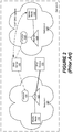
Figure 1 is a block diagram of a conventional communications system. -
Figure 2 is a block diagram of a conventional communications system. -
Figures 3 through 6 are block diagrams of communication systems in accordance with some embodiments of the present inventive concept. -
Figure 7 is a block diagram of anetwork address translator 64+ (NAT64+) in accordance with some embodiments of the present inventive concept. -
Figure 8 is a block diagram of an ILNP address including an identifier portion and a locator portion in accordance with some embodiments of the present inventive concept. -
Figure 9 is a block diagram of a network node/user device in accordance with some embodiments of the present inventive concept. -
Figures 10-14 are flow charts illustrating operations and methods for communicating between at least one identifier locator network protocol (ILNP) enabled mobile node running Internet protocol version 6 (IPv6) and a destination device running IPv4 in accordance with some embodiments of the present inventive concept. - The present inventive concept now will be described more fully hereinafter with reference to the accompanying drawings, in which embodiments of the inventive concept are shown. However, this inventive concept is not to be construed as limited to the embodiments set forth herein.
- Identifier locator network protocol (ILNP) is an identifier locator split protocol embedded in Internet protocol version 6 (IPv6). ILNP is a host centric solution, which typically requires no update to the operator's network infrastructure. As discussed above, the identifier locator network protocol (ILNP) is a network protocol designed to separate the two functions of network addresses. Thus, an ILNP address has both an identifier portion, which is static, and a locator portion, which is dynamic, i.e., it changes based on the current location of the mobile node in the network. ILNP provides the transport layers of the system with the static identifier, for example, a name of the user device, which allows seamless mobility and multi-homing as will be discussed further herein. The identifier portion of the ILNP address is 64 bits long. The identifier portion it not topologically significant and names a logical/virtual/physical node, not an interface. The identifier portion remains constant during the lifetime of the transport session. Multiple identifiers can be used by a node, but not during the same transport session. The locator portion of the ILNP address, on the other hand, is dynamic and, therefore, can change value during the lifetime of the transport session and multiple locators can be used simultaneously. A locator portion of the ILNP address enables mobility, multi-homing and multi-path transport protocol.
- As used herein, a "transport session" refers to an established connection between two hosts/systems/nodes. When a mobile node tries to connect to a destination node there is a negotiation that happens between the mobile node and/or the related system and the destination node/system. In brief, the negotiation involves the terms of how data will be transferred between the mobile node and the destination node. Once the negotiation is complete, data transfer between the nodes can begin over the established "transport session." This session can be terminated when communication between the nodes is complete. Thus, as discussed above, the identifier portion of the ILNP address remains static for a given node during the transport session. However, the same node can have a different identifier portion during a different session, for example, if the session is terminated and then a new session is established, the same node may have two different identifier portions. The locator portion of the ILNP address is dynamic within the session and can change based on the current position of the mobile node.
- ILNP is incrementally deployable and is expected to coexist with IPv6 and Internet Protocol version 4 (IPv4). In other words, although IPv6 is being developed, IPv4 may remain in use. Thus, a mechanism is needed to enable connectivity between IPv6-only end user devices, and IPv4 destinations. Currently, a network address translator 64 (NAT 64) technology has been developed to enable connectivity between the IPv6 and IPv4 devices, which will be discussed with respect to
Figures 1 and2 below. - As illustrated in
Figures 1 and2 , Domain A includes first andsecond networks 120, 120', a domain name server (DNS)server 150 and anIPv4 device 150. As further illustrated inFigure 1 , eachnetwork 120, 120' in Domain A includes amobile node 110, 110', anNAT64 123, 123' and a domain name server 64 (DNS64) 130, 130'. The mobile node 110,110' is an ILNP-enabled mobile node, which is attached to an ILNP enablednetwork 120, 120'. As illustrated, theNAT64 123 communicates with the DNS64, which is configured to convert an IPv4 address to a "fake" IPv6 address. As used herein, a "fake" address refers to an address created by the system such that an IPv4 device looks like an IPv6 device to the IPv6 devices trying to communicate therewith. This facilitates communication between the IPv6 device and the IPv4 device. Thus, when themobile node 110, 110', which is an IPv6 device, establishes contact with theIPv4 destination device 150, the DNS64 converts the IPv4 address of theIPv4 device 150 to a fake IPv6 address for thedestination device 150. This fake IPv6 address of theIPv4 device 150 is presented to the IPv6mobile device 110, 110' as if thedestination device 150 were also running IPv6. - The
NAT64 123, 123' that sits between themobile device 110, 110' and thedestination device 150 is configured to convert the IPv4 packets from thedestination device 150 to IPv6 packets using the fake IPv6 address assigned by theDNS64 130, 103' for receipt by the IPv6mobile device 110, 110'. Similarly, theNAT64 123, 123' is configured to convert the IPv6 packets from themobile node 110, 110' to IPv4 packets for thedestination device 150. - Referring now to
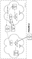
Figure 1 , when themobile node 110 in thefirst network 120 beings operation in the IPv6 network, themobile node 110 sends a DNS Update registering its ILNP information with theDNS server 140. In other words, themobile node 110 registers its ILNP identifier in theDNS server 140 with its associated/selected ILNP locator(s). In some embodiments, this may be accomplished by themobile node 110 sending the message to theDNS64 130, which would then send the message on to theDNS server 140. When themobile node 110 decides to establish a session with theIPv4 device 150, themobile node 110 will send a DNS lookup to theDNS64 130. As discussed above, as illustrated inFigure 8 below, theILNP address 800 includes both a staticILNP identifier portion 890 and anILNP locator portion 891. Responsive to the DNS lookup, theDNS64 130 assigns a fake IPv6 address to theIPv4 device 150 and provides this fake IPv6 address to themobile node 110 as if it were the real address of thedestination device 150. Themobile node 110 uses the fakeIPv6 address to connect to theIPv4 device 150 while theNAT64 123 translates the headers of the packets. - Referring now to
Figure 2 , when the mobile node 110' moves to the second network 120', the mobile node 110' sends an ILNP DNS update to theDNS server 140 to update its ILNP locator(s), i.e. to inform the DNS server that the mobile node 110' has moved from thefirst network 120 to the second network 120'. As is understood, the ILNP identifier stays static during the session. In a conventional system, when themobile node 110, 110' moves from thefirst network 120 to the second network 120', themobile node 110, 110' will lose its current session after the ILNP locator(s) are updated at theDNS server 140 as themobile node 110, 110' will stop using theNAT64 123 infirst network 120 and start using the NAT64 123' in the second network 120'. Losing the session when switching betweenNAT64 123 and NAT64 123' affects the seamless operation of the network. - Accordingly, some embodiments of the present inventive concept enable seamless connectivity between Internet protocol version 6 (IPv6) only end user devices and Internet Protocol version 4 (IPv4) destinations by enabling a full ILNP session therebetween. In particular, embodiments of the present inventive concept provide an improved NAT64, referred to herein as "NAT64+", and improved DNS64, referred to herein as "DNS64+". Use of the NAT64+ and the DNS64+ in combination with a virtual root server enable a mobile device to maintain the session even when moving between multiple networks in the same domain. The virtual root server allows foreign/visited NAT64+ and DNS64+ to learn about the mobile node and related ongoing sessions with IPv4 destination devices and take the necessary steps to provide seamless mobility of the mobile node, i.e. the session can be maintained through multiple NAT64+s. Thus, embodiments of the present inventive concept provide seamless network centric IP mobility as will be discussed further herein with respect to
Figures 3 through 14 . - As used herein, a "foreign/visited" NAT64+ is a NAT64+ positioned in a network different from the network the mobile node was present in when the session was established, i.e. not the home NAT64+. Similarly, a "foreign/visited" DNS64+ is a DNS64+ positioned in a network different from the network the mobile node was present in when the session was established, i.e. not the home DNS64+. Furthermore, as used herein, NAT64+(X) and DNS64+(X) notations refer to a NAT64+ and DNS64+ entities in accordance with embodiments discussed herein running in Network X.
- The assumption is that, generally, operators interested in deploying ILNP would prefer to avoid going through another major update to their client devices and, instead, turn on ILNP in parallel with IPv6. Furthermore, embodiments of the present inventive concept assume that a hierarchical DNS64+ entities in accordance with embodiments discussed herein have been distributed within the domain, for example, Domain A. The root of such distribution is called "Domain
virtual root 64" or "root 64." Root64, referred to herein as virtual root server, is configured to store bindings between ILNP identifiers and can be securely reached by any DNS64+ entities within the Domain. A virtual root server cannot be reached by a DNS64+ entity located outside its assigned domain. Between different Domains, virtual root servers communicate with virtual root servers. - It is further assumed that the mobile node will continue to use ILNP while roaming between different networks and across different NAT64+s located within a particular Domain. As used herein, the IPv4 devices (destinations) are considered to be static devices/destinations, i.e. these are not mobile nodes.
-
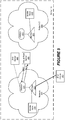
Figures 3-6 are block diagrams illustrating various aspects of systems including NAT64+s, DNS64+s and virtual root servers in accordance with embodiments of the present inventive concept. Embodiments and operations in accordance with the inventive concept will now be discussed with respect toFigures 3-6 . - Referring first to
Figure 3 , the Domain A includes first andsecond networks 320, 320', a domain name server (DNS)server 340, avirtual root server 360 and an IPv4 device (destination device) 350. It will be understood that although Domain A only includes two networks and a single DNS server, virtual root server and destination device, embodiments of the present inventive concept are not limited to this configuration. For example, any number of each of these components may be present in Domain A without departing from the scope of the present inventive concept. - As illustrated in
Figure 3 , thedestination device 350 can be located in Domain A or anywhere else outside Domain A without departing from the scope of the present inventive concept. Thedestination device 350 is illustrated outside Domain A inFigures 4-6 for ease of discussion; however, embodiments are not limited to this configuration. - As further illustrated in
Figure 3 , eachnetwork 320, 320' in Domain A includes aNAT64+ 321, 321' and aDNS64+ 331, 331'. Themobile node 310 is positioned in thefirst network 320 inFigure 3 . Themobile node 310 is an ILNP-enabled mobile node running IPv6, which is attached to an ILNP enablednetwork 320. When themobile node 310 attempts to connect to theIPv4 device 350, themobile node 310 runs a DNS lookup, which involves theDNS64+ 331, as illustrated inFigure 3 . TheDNS64+ 331 sends a binding identifiers create (BIC) message to thevirtual root server 360 as illustrated inFigure 3 . The BIC message includes an ILNP address of themobile node 310 running IPv6, a fake ILNP address of adestination device 350 running IPv4 assigned by the DNS64+ and an ILNP address of the DNS64+ server (home DNS64+). The fake ILNP address for thedestination device 350 includes a full "real" address of thedestination device 350 in the identifier portion of the fake ILNP address. In some embodiments, the BIC message may further include a time stamp. - As discussed above, the
ILNP address 800 ofFigure 8 of the mobile node includes anidentifier portion 890 and alocator portion 891. Theidentifier portion 890 is static during a session and is configured to identify the mobile node during the session. Thelocator portion 891 is dynamic and identifies at least one current location of the mobile node. - As used herein, the "home" DNS64+ or NAT64+ is the DNS64+ or the NAT64+ in the network the mobile node was in when the session was established. As used herein, the "real" address of the
destination device 350 is the actual IPv4 address of thedestination device 350, i.e. not the "fake" address assigned by the DNS64+. - Upon receiving the BIC message, the
virtual root server 360 creates a binding between the ILNP address of themobile node 310 and the fake ILNP address of thedestination device 350 and stores the binding at thevirtual root server 360. The virtual root server sends a binding identifier acknowledgement (BIA) message to the DNS64+ server. - Referring now to
Figure 4 , each time themobile node 310 attaches to a new network, it gets a new ILNP locator, but the ILNP identifier stays static. When themobile node 310, 310' gets a new locator, it has to update the DNS entry for the mobile node during the current session. Thus, as illustrated inFigure 4 , the mobile node 310' has moved into the second network 320' and now sends an ILNP DNS update to theDNS server 340. The DNS64+ 331' obtains updated locator information based on an identifier associated with the mobile node 310' that is included in the ILNP DNS update message and updates thevirtual root server 360 with the new locator(s). In particular, as illustrated inFigure 4 , the DNS64+ 331' (visited DNS64+) is configured to send a binding identifier update (BIU) message to thevirtual root server 360. The BIU message includes both the static identifier portion of the ILNP address of the mobile node 310' and the new ILNP locator portion of the ILNP address of the mobile node 310'. It will be understood that the DNS64+ 331' only needs to perform this operation once upon device attachment. It will be understood that the BIU message is used when the visited DNS64+ 331' is not creating a new fake ILNP address. - Responsive to receipt of the BIU message from the DNS64+ 331', the
virtual root server 360 is configured to determine if at least one binding exists for the mobile node 310' based on the static identifier portion of the ILNP address of the mobile node. In other words, thevirtual root server 360 checks its cache to see if a binding exists for the mobile node 310' having the static identifier associated therewith. Thevirtual root server 360 then sends a binding identifier response (BIR) message to the DNS64+ 331'. The BIR message either indicates that no binding currently exists for the mobile node 310' if it is determined that at least one binding does not exist in its cache for the mobile node 310' having the associated identifier; or provides a list of all available bindings for the mobile node 310' if it is determined that at least one binding exists in its cache. - Referring now to
Figure 5 , receipt of the BIU triggers thevirtual root server 360 to alert thehome DNS64+ 331 that the mobile node has new locator(s). Thus, as illustrated inFigure 5 , thevirtual root server 360 is configured to send a mobile locator update (MLU) message to thehome DNS64+ 331. Thus, the MLU includes the new locator(s) for the mobile node 310' having the associated identifier. The communication between thevirtual root server 360 and thehome DNS64+ 331 is possible because upon creating the binding in its cache, thevirtual root server 360 also stores the ILNP address of theDNS64+ 331 that sends the BIC discussed above with respect toFigure 3 . Thehome DNS64+ 331 is configured to send a mobile locator acknowledgement (MLA) message to thevirtual root server 360 responsive to receipt of the MLU message. It will be understood that themobile node 310, 310' is not involved or aware of this exchange between thevirtual root server 360 and theDNS64+ 331, thus, enabling a more seamless process in accordance with embodiments discussed herein. - Referring now to
Figure 6 , whenever thehome NAT64+ 321 removes a binding between a fake ILNP address associated with thedestination device 350 and the ILNP of themobile device 310, 310', it alerts theDNS64+ 331. TheDNS64+ 331 requests that thevirtual root server 360 remove the binding from its cache. In particular, theDNS64+ 331 sends a binding delete (BD) message to thevirtual root server 360 requesting removal of the binding. - The
virtual root server 360 receives the BD message from thehome DNS64+ 331 and determines if the binding between the ILNP address for the mobile node and the fake ILNP address for the destination device exists. If the binding exists in the cache at thevirtual root server 360, thevirtual root server 360 removes the binding at thevirtual root server 360 and sends a binding delete acknowledgment (BDA) message to thehome DNS64+ 331. In this scenario, the BDA indicates removal of the requested binding. - However, if it is determined that no binding exits in the cache of the
virtual root server 360, the BDA message indicates that no binding between the ILNP address for themobile node 310, 310' and the fake ILNP address for thedestination device 350 exists. It will be understood that only the DNS64+ that creates a binding at the virtual root server can delete the binding. - As illustrated in
Figure 7 , in some embodiments of the present inventive concept, theNAT64+ 721 includes a lightweight destination agent (LDA) 722. The LDA allows virtual dynamic anchoring of a session as will be discussed further below. - Referring now to
Figure 9 , a block diagram of a network node and/or user device 995 in accordance with some embodiments will be discussed. When used for a network node, the illustrated components may be included in any component of the communication system illustrated inFigures 3-6 . When implemented as the user device, the illustrated components may be included in the user phone device and/or the user network device without departing from the scope of the present inventive concept. - The user network device can be any type of electronic communication device that can operated by a user to initiate or receive calls, and may include, but is not limited to, fixed/mobile/transportable terminals (e.g., smart phones, tablet computers, etc.), televisions, gaming consoles, and desktop computers.
- As illustrated in
Figure 9 , the network node/user device 995 includes aprocessor circuit 911, memory circuitry/devices 925, and one or more network interfaces 935. The one ormore network interfaces 935 can include any type of wired and/or wireless communication interface (e.g., cellular, wireless local area network, wireless metropolitan area network, etc.). - The
processor circuit 911 may include one or more data processing circuits, such as a general purpose and/or special purpose processor (e.g., microprocessor and/or digital signal processor). Theprocessor circuit 911 is configured to execute computer program instructions fromfunctional modules 927 in thememory devices 925, described below as a computer readable medium, to perform some or all of the operations and methods that are described above for one or more of the embodiments disclosed herein, such as the embodiments ofFigures 3-8 and10-14 . - As discussed above, the DNS64+ in accordance with embodiments discussed herein communicates with the virtual root server to enable seamless mobility. Examples of implementation of the NAT64+, DNS64+ and virtual root server in accordance with embodiments of the present inventive concept will be discussed.
- Referring back to
Figures 3-6 , when themobile node 310 establishes a connection with theIPv4 device 350, the IPv4 device is assigned a fake ILNP address by theDNS64+ 331. Assigning the IPv4 device a fake ILNP address instead of a fake IPv6 address may allow the locator portion of the fake ILNP address to change freely without impacting the session continuity or requiring unnecessary tunneling to the mobile node. Some embodiments of the present inventive concept use a fake ILNP locator for the IPv4 device, the locator is also configured by the home NAT64+ ILNP address. As discussed above, thevirtual root server 360 creates a binding between the mobile node's 310 ILNP address and the fake ILNP address assigned to theIPv4 device 350. As discussed above, the fake ILNP address includes a real address of theIPv4 device 350 in the identifier portion thereof. - In other words, the fake ILNP identifier allows insertion of all necessary information in the 64 bit length space of the identifier portion of the ILNP address. In particular, the leftmost 32 bits of the 64 bit fake ILNP identifier includes the real address of the
IPv4 device 350. As discussed above with respect toFigure 7 , each NAT64+ in accordance with embodiments discussed herein includes an LDA. The LDA allows virtual dynamic anchoring of the session with the real destination. When using ILNP, themobile node 310 does not use a mobility anchor point. The static anchoring remains at thehome NAT 64+ 321. - Using the fake ILNP address assigned by the DNS64+ (1) 331 (the DNS64+ of
network 1 320), themobile node 310 establishes a session with theIPv4 device 350, which consists of exchanging ILNP packets with the NAT64+(1) 321 (the NAT64+ ofnetwork 1 320). - Upon switching to
Network 2 320', the mobile node 310' follows ILNP procedure and updates its DNS with its new locator(s) obtained fromnetwork 2 320'. It will be understood that using the mobile node's identifier sent in the ILNP DNS update, the DNS64+(2) 331' updates thevirtual root server 360 and also discovers the existing binding which involves the home NAT64+ 321 (NAT64+(1)). Thevirtual root server 360 updates thehome DNS64+ 331 with the new ILNP locator associated with the mobile node 310'. - After receiving an update from the
virtual root server 360, thehome DNS64+ 331 alerts thehome NAT64+ 321 about the new locator associated with the mobile node 310'. Thus, thehome NAT64+ 321 translates the incoming IPv4 packets to the correct ILNP locator for the mobile node. For at least these reasons, embodiments of the present inventive concept provide more seamless communications between IPv6 and IPv4 devices. - Operations in accordance with some embodiments of the present inventive concept will now be discussed with respect to the flow charts of
Figures 10-14 . Referring first toFigure 10 , operations for communicating between at least one ILNP enabled mobile node running IPv6 and a destination device running IPv4 will be discussed. The mobile node is attached to an IPv6 network in an IPv6 domain. Operations begin atblock 1000 by receiving, at a virtual root server, a BIC message from a DNS64+ associated with the IPv6 network. The BIC message includes an ILNP address of the mobile node running IPv6, a fake ILNP address of a destination device running IPv4 assigned by the DNS64+ and an ILNP address of the DNS64+. The fake ILNP address includes a full real address of the destination device. A binding is created between the ILNP address of the mobile node and the fake ILNP address of the destination device (block 1002). The binding is stored at the virtual root server (block 1004). A BIA message is sent to the DNS64+ (block 1006). In some embodiments, the BIC message may include a time stamp. - As discussed above, the ILNP address of the mobile node includes an identifier portion and a locator portion. The identifier portion is static during a session and identifies the mobile node during the session. The locator portion is dynamic and identifies at least one current location of the mobile node.
- Referring now to
Figure 11 , operations ofblock 1000 ofFigure 10 are preceded by operations ofblocks Figure 12 . Operations begin atblock 1100 by receiving, at a DNS64+ server, a request from the mobile node running IPv6 for a session to be established between the mobile node running IPv6 and the destination device running internet protocol version 4 (IPv4). The DNS64+ assigns the fake IPv6 ILNP address to the destination device running IPv4 responsive to the request (block 1102). - Referring now to
Figure 12 , the IPv6 network may be a first IPv6 network in the IPv6 domain and wherein the DNS64+ may be a home DNS64+. Operations continue atblock 1200 by attaching the mobile node to a second IPv6 network in the IPv6 domain. A new ILNP locator portion of the ILNP address is received for the mobile node (block 1202). The new ILNP locator is sent to a DN64+ server for the IPv6 domain (block 1204). At a new DNS64+ associated with the second IPv6 network, the new ILNP locator portion of the ILNP address of the mobile node is received (block 1206). A BIU message is sent to the virtual root server (block 1208). The BIU message includes the static identifier portion of the ILNP address of the mobile node and the new ILNP locator portion of the mobile node. - Referring now to
Figure 13 , operations continue atblock 1300 by determining, at the virtual root server, if at least one binding exists for the mobile node based on the static identifier portion of the ILNP address of the mobile node responsive to the BIU message (block 1300). A BIR message is sent to the new DNS64+ (block 1302). The BIR message indicates that no binding currently exists for the mobile node if it is determined that at least one binding does not exist; or provides a list of all available bindings for the mobile node if it is determined that at least one binding exists. An MLU message is sent from the virtual root server to the home DNS64+ responsive to a BIU message indicating that at least one binding exists for the mobile node (block 1304). The MLU message updates the ILNP locator at the home DNS64+. An MLA message is sent from the home DNS64+ to the virtual root server responsive to the MLU message (block 1306). - Referring now to
Figure 14 , operations continue atblock 1400 by removing, at a NAT64+ associated with the first IPv6 network, a binding between the ILNP address for the mobile node and the fake ILNP address for the destination The home DNS64+ is alerted of removal of the binding (block 1402). A BD message is sent from the home DNS64+ to the virtual root server (block 1404). The BD message is received at the virtual root server from the home DNS64+ (block 1404). It is determined if the binding between the ILNP address for the mobile node and the fake ILNP address for the destination device exists (block 1406). The binding at the virtual root server is removed if the binding is determined to exist (block 1408). A BDA message is sent to the home DNS64+ (block 1410). The BDA message may indicate that no binding between the ILNP address for the mobile node and the fake ILNP address for the destination device exists if it is determined that the binding does not exist. - In the above-description of various embodiments of the present inventive concept, it is to be understood that the terminology used herein is for the purpose of describing particular embodiments only and is not intended to be limiting of the inventive concept. Unless otherwise defined, all terms (including technical and scientific terms) used herein have the same meaning as commonly understood by one of ordinary skill in the art to which this inventive concept belongs. It will be further understood that terms, such as those defined in commonly used dictionaries, should be interpreted as having a meaning that is consistent with their meaning in the context of this specification and the relevant art and will not be interpreted in an idealized or overly formal sense expressly so defined herein.
- When an element is referred to as being "connected", "coupled", "responsive", or variants thereof to another element, it can be directly connected, coupled, or responsive to the other element or intervening elements may be present. In contrast, when an element is referred to as being "directly connected", "directly coupled", "directly responsive", or variants thereof to another element, there are no intervening elements present. Like numbers refer to like elements throughout. Furthermore, "coupled", "connected", "responsive", or variants thereof as used herein may include wirelessly coupled, connected, or responsive. As used herein, the singular forms "a", "an" and "the" are intended to include the plural forms as well, unless the context clearly indicates otherwise. Well-known functions or constructions may not be described in detail for brevity and/or clarity. The term "and/or" or "/" includes any and all combinations of one or more of the associated listed items.
- As used herein, the terms "comprise", "comprising", "comprises", "include", "including", "includes", "have", "has", "having", or variants thereof are open-ended, and include one or more stated features, integers, elements, steps, components or functions but does not preclude the presence or addition of one or more other features, integers, elements, steps, components, functions or groups thereof. Furthermore, as used herein, the common abbreviation "e.g.", which derives from the Latin phrase "exempli gratia," may be used to introduce or specify a general example or examples of a previously mentioned item, and is not intended to be limiting of such item. The common abbreviation "i.e.", which derives from the Latin phrase "id est," may be used to specify a particular item from a more general recitation.
- Example embodiments are described herein with reference to block diagrams and/or flowchart illustrations of computer-implemented methods, apparatus (systems and/or devices) and/or computer program products. It is understood that a block of the block diagrams and/or flowchart illustrations, and combinations of blocks in the block diagrams and/or flowchart illustrations, can be implemented by computer program instructions that are performed by one or more computer circuits. These computer program instructions may be provided to a processor circuit of a general purpose computer circuit, special purpose computer circuit, and/or other programmable data processing circuit to produce a machine, such that the instructions, which execute via the processor of the computer and/or other programmable data processing apparatus, transform and control transistors, values stored in memory locations, and other hardware components within such circuitry to implement the functions/acts specified in the block diagrams and/or flowchart block or blocks, and thereby create means (functionality) and/or structure for implementing the functions/acts specified in the block diagrams and/or flowchart block(s).
- These computer program instructions may also be stored in a tangible computer-readable medium that can direct a computer or other programmable data processing apparatus to function in a particular manner, such that the instructions stored in the computer-readable medium produce an article of manufacture including instructions which implement the functions/acts specified in the block diagrams and/or flowchart block or blocks.
- A tangible, non-transitory computer-readable medium may include an electronic, magnetic, optical, electromagnetic, or semiconductor data storage system, apparatus, or device. More specific examples of the non-transitory computer-readable medium would include the following: a portable computer diskette, a random access memory (RAM) circuit, a read-only memory (ROM) circuit, an erasable programmable read-only memory (EPROM or Flash memory) circuit, a portable compact disc read-only memory (CD-ROM), and a portable digital video disc read-only memory (DVD/BlueRay).
- The computer program instructions may also be loaded onto a computer and/or other programmable data processing apparatus to cause a series of operational steps to be performed on the computer and/or other programmable apparatus to produce a computer-implemented process such that the instructions which execute on the computer or other programmable apparatus provide steps for implementing the functions/acts specified in the block diagrams and/or flowchart block or blocks. Accordingly, embodiments of the present inventive concept may be embodied in hardware and/or in software (including firmware, resident software, micro-code, etc.) that runs on a processor such as a digital signal processor, which may collectively be referred to as "circuitry," "a module" or variants thereof.
- It should also be noted that in some alternate implementations, the functions/acts noted in the blocks may occur out of the order noted in the flowcharts. For example, two blocks shown in succession may in fact be executed substantially concurrently or the blocks may sometimes be executed in the reverse order, depending upon the functionality/acts involved. Moreover, the functionality of a given block of the flowcharts and/or block diagrams may be separated into multiple blocks and/or the functionality of two or more blocks of the flowcharts and/or block diagrams may be at least partially integrated. Finally, other blocks may be added/inserted between the blocks that are illustrated. Moreover, although some of the diagrams include arrows on communication paths to show a primary direction of communication, it is to be understood that communication may occur in the opposite direction to the depicted arrows.
- Many different embodiments have been disclosed herein, in connection with the above description and the drawings. It will be understood that it would be unduly repetitious and obfuscating to literally describe and illustrate every combination and subcombination of these embodiments. Accordingly, the present specification, including the drawings, shall be construed to constitute a complete written description of various example combinations and subcombinations of embodiments and of the manner and process of making and using them, and shall support claims to any such combination or subcombination.
- Many variations and modifications can be made to the embodiments without substantially departing from the principles of the present inventive concept. All such variations and modifications are intended to be included herein within the scope of the present inventive concept.
Claims (13)
- A system including at least one identifier locator network protocol, ILNP, enabled mobile node (310, 310') running Internet protocol version 6, IPv6, the mobile node being arranged to attach a first IPv6 network (320) in an IPv6 domain (Domain A), the system comprising:a virtual root server (360) configured to:receive a binding identifiers create, BIC, message from a home domain name system 64, DNS64, server (331) associated with the IPv6 network, wherein the BIC message includes an ILNP address of the mobile node (310, 310') running IPv6, a fake ILNP address of a destination device (350, 350') running internet protocol version 4, IPv4, assigned by the home DNS64 server (331) and an ILNP address of the home DNS64 server (331) and wherein the fake ILNP address includes a full real address of the destination device (350, 350');create a binding between the ILNP address of the mobile node (310, 310') and the fake ILNP address of the destination device (350, 350');store the binding; andsend a binding identifier acknowledgement, BIA, message to the home DNS64 server (331),wherein the home DNS64 server (331) is configured to receive a request from the mobile node (310, 310') running IPv6 for a session to be established between the mobile node (310, 310') running IPv6 and the destination device (350, 350') running IPv4 and assign the fake ILNP address to the destination device (350, 350') running IPv4 responsive to the request,wherein the session between the mobile node (310, 310') running IPv6 and the destination device (350, 350') running IPv4 is established using the fake ILNP address and wherein establishing the session comprises exchanging ILNP packets with a home network address translator 64, NAT64, (321) associated with the first IPv6 network (320),wherein the ILNP address of the mobile node (310, 310') includes an identifier portion and a locator portion,wherein the identifier portion is static during a session and is configured to identify the mobile node (310, 310') during the session;wherein the locator portion is dynamic and identifies a current location of the mobile node (310, 310'),wherein the mobile node (310, 310') is arranged to attach to a second IPv6 network (320') in the IPv6 domain (Domain A), receive a new ILNP locator portion of the ILNP address for the mobile node (310, 310') and send the new ILNP locator portion to a DNS server (340) for the IPv6 domain,the system further comprising a new DNS64 server (331') associated with the second IPv6 network (320') that is configured to receive the new ILNP locator portion of the ILNP address of the mobile node (310, 310') and send a binding identifier update, BIU, message to the virtual root server (360), the BIU message including the static identifier portion of the ILNP address of the mobile node (310, 310') and the new ILNP locator portion of the ILNP address of the mobile node (310, 310'),wherein the virtual root server (360) is further configured to:determine if at least one binding exists for the mobile node (310, 310') based on the static identifier portion of the ILNP address of the mobile node responsive to the BIU message;send a binding identifier response, BIR, message to the new DNS64 server (331'), the BIR message indicating that no binding currently exists for the mobile node if it is determined that at least one binding does not exist or providing a list of all available bindings for the mobile node if it is determined that at least one binding exists; andsend a mobile locator update, MLU, message to the home DNS64 (331) responsive to a BIU message indicating that at least one binding exists for the mobile node, the MLU message updating the ILNP locator at the home DNS64 (331),wherein the home DNS64 (331) is configured to send a mobile locator acknowledgement, MLA, message to the virtual root server (360) responsive to the MLU message, and alert the home NAT64 (321) about the new ILNP locator portion of the ILNP address of the mobile node (310, 310').
- The system of Claim 1, wherein the BIC message further includes a time stamp.
- The system of Claim 1, wherein the home NAT64 (321) is configured to:remove a binding between the ILNP address for the mobile node and the fake ILNP address for the destination device (350, 350'); andalert the home DNS64 (331) of removal of the binding such that the DNS64 sends a binding delete, BD, message from the home DNS64 (331) to the virtual root server (360).
- The system of Claim 3, wherein the virtual root server (360) is further configured to:receive the BD message from the home DNS64 (331);determine if the binding between the ILNP address for the mobile node (310, 310') and the fake ILNP address for the destination device (350, 350') exists;remove the binding at the virtual root server (360) if the binding is determined to exist; andsend a binding delete acknowledgment, BDA, message to the home DNS64 (331).
- The system of Claim 4, wherein the BDA message indicates that no binding between the ILNP address for the mobile node (310, 310') and the fake ILNP address for the destination device (350, 350') exists if it is determined that the binding does not exist.
- The system of Claim 1, wherein the fake ILNP address of the destination device (350, 350') comprises a locator portion and an identifier portion, the identifier portion being a 64 bit length space including a 32 bit identifier of the full real address of the destination device (350, 350').
- The system of Claim 6, further comprising a network address translator 64, NAT64, (321') associated with the IPv6 network (320'), wherein the home NAT64 (321) and the NAT64 (321') comprises a lightweight destination agent, LDA, allowing virtual dynamic anchoring of a session.
- A method for communicating between at least one identifier locator network protocol, ILNP, enabled mobile node running Internet protocol version 6, IPv6, and a destination device running internet protocol version 4, IPv4, the mobile node being arranged to attach to a first IPv6 network in an IPv6 domain, the method comprising:receiving (1000), at a virtual root server, a binding identifiers create, BIC, message from a home domain name system 64, DNS64, server associated with the IPv6 network, wherein the BIC message includes an ILNP address of the mobile node (310, 310') running IPv6, a fake ILNP address of the destination device running IPv4 assigned by the home DNS64 server and an ILNP address of the home DNS64 server and wherein the fake ILNP address includes a full real address of the destination device;creating (1002) a binding between the ILNP address of the mobile node and the fake ILNP address of the destination device;storing (1004) the binding;sending (1006) a binding identifier acknowledgement, BIA, message to the home DNS64 server;receiving (1100), at the home DNS64 server, a request from the mobile node running IPv6 for a session to be established between the mobile node running IPv6 and the destination device running IPv4; andassigning (1102), at the home DNS64 server, the fake ILNP address to the destination device running IPv4 responsive to the request,wherein the session between the mobile node (310, 310') running IPv6 and the destination device running IPv4 is established using the fake ILNP address and wherein establishing the session comprises exchanging ILNP packets with a home network address translator 64, NAT64, (321) associated with the first IPv6 network,wherein the ILNP address of the mobile node includes an identifier portion and a locator portion,wherein the identifier portion is static during a session and identifies the mobile node during the session,wherein the locator portion is dynamic and identifies a current location of the mobile node, the method further comprising:attaching (1200) the mobile node to a second IPv6 network in the IPv6 domain;receiving (1202) a new ILNP locator portion of the ILNP address for the mobile node;sending (1204) the new ILNP locator portion to a DNS server for the IPv6 domain;receiving (1206), at a new DNS64 server associated with the second IPv6 network, the new ILNP locator portion of the ILNP address of the mobile node;sending (1208) a binding identifier update, BIU, message to the virtual root server, the BIU message including the static identifier portion of the ILNP address of the mobile node and the new ILNP locator portion of the ILNP address of the mobile node;determining (1300), at the virtual root server, if at least one binding exists for the mobile node based on the static identifier portion of the ILNP address of the mobile node responsive to the BIU message;sending (1302) a binding identifier response, BIR, message to the new DNS64 server, the BIR message indicating that no binding currently exists for the mobile node if it is determined that at least one binding does not exist or providing a list of all available bindings for the mobile node if it is determined that at least one binding exists;sending (1304), from the virtual root server, a mobile locator update, MLU, message to the home DNS64 responsive to a BIU message indicating that at least one binding exists for the mobile node, the MLU message updating the ILNP locator at the home DNS64; andsending (1306), from the home DNS64, a mobile locator acknowledgement, MLA, message to the virtual root server responsive to the MLU message, and alerting the home NAT64 (321) about the new ILNP locator portion of the ILNP address of the mobile node (310, 310').
- The method of Claim 8, wherein the BIC message further includes a time stamp.
- The method of Claim 8, further comprising:removing (1400), at the home NAT64, a binding between the ILNP address for the mobile node and the fake ILNP address for the destination device; andalerting (1402) the home DNS64 of removal of the binding; andsending (1404) a binding delete, BD, message from the home DNS64 to the virtual root server.
- The method of Claim 10, further comprising:receiving (1406), at the virtual root server, the BD message from the home DNS64;determining (1408) if the binding between the ILNP address for the mobile node and the fake ILNP address for the destination device exists;removing (1410) the binding at the virtual root server if the binding is determined to exist; andsending (1412) a binding delete acknowledgment, BDA, message to the home DNS64.
- The method of Claim 11, wherein the BDA message indicates that no binding between the ILNP address for the mobile node (310, 310') and the fake ILNP address for the destination device (350, 350') exists if it is determined that the binding does not exist.
- The method of Claim 8, wherein the fake ILNP address of the destination device (350, 350') comprises a locator portion and an identifier portion, the identifier portion being a 64 bit length space including a 32 bit identifier of the full real address of the destination device (350, 350').
Applications Claiming Priority (2)
| Application Number | Priority Date | Filing Date | Title |
|---|---|---|---|
| US13/732,044 US9185071B2 (en) | 2012-12-31 | 2012-12-31 | Methods and systems for seamless network communications between devices running internet protocol version 6 and internet protocol version 4 |
| PCT/IB2013/061288 WO2014102714A1 (en) | 2012-12-31 | 2013-12-23 | Methods and systems for seamless network communications between ipv4 and ipv6 devices |
Publications (2)
| Publication Number | Publication Date |
|---|---|
| EP2939399A1 EP2939399A1 (en) | 2015-11-04 |
| EP2939399B1 true EP2939399B1 (en) | 2018-03-14 |
Family
ID=50112950
Family Applications (1)
| Application Number | Title | Priority Date | Filing Date |
|---|---|---|---|
| EP13830056.1A Active EP2939399B1 (en) | 2012-12-31 | 2013-12-23 | Methods and system for seamless network communications between ipv4 and ipv6 devices |
Country Status (4)
| Country | Link |
|---|---|
| US (1) | US9185071B2 (en) |
| EP (1) | EP2939399B1 (en) |
| CN (1) | CN104995902B (en) |
| WO (1) | WO2014102714A1 (en) |
Families Citing this family (16)
| Publication number | Priority date | Publication date | Assignee | Title |
|---|---|---|---|---|
| US9398505B2 (en) | 2013-03-14 | 2016-07-19 | Google Inc. | Reducing stream interruptions during network handover |
| US9241292B2 (en) | 2013-09-25 | 2016-01-19 | Google Inc. | Seamless application connectivity |
| WO2015136842A1 (en) * | 2014-03-13 | 2015-09-17 | 日本電気株式会社 | Network management device, network system, network management method, and recording medium |
| US9826436B2 (en) | 2014-09-29 | 2017-11-21 | At&T Intellectual Property I, L.P. | Facilitation of mobility management across various radio technologies |
| US9729480B2 (en) | 2015-02-04 | 2017-08-08 | Kno2 Llc | Interoperable clinical document-exchange system |
| US10164934B1 (en) * | 2015-04-03 | 2018-12-25 | Sprint Communications Company L.P. | User device parameter allocation based on internet protocol version capabilities |
| US10165091B1 (en) * | 2015-04-03 | 2018-12-25 | Sprint Communications Company L.P. | User device parameter allocation based on internet protocol version capabilities |
| US10164869B1 (en) * | 2015-04-03 | 2018-12-25 | Sprint Communications Company, L.P. | Facilitating routing of data based on an internet protocol version capability of a user device |
| US10645057B2 (en) * | 2016-06-22 | 2020-05-05 | Cisco Technology, Inc. | Domain name system identification and attribution |
| CN106413034A (en) * | 2016-09-30 | 2017-02-15 | 深圳前海弘稼科技有限公司 | Binding method, binding system, intelligent device and planting device |
| WO2018138544A1 (en) | 2017-01-24 | 2018-08-02 | Telefonaktiebolaget Lm Ericsson (Publ) | Using location identifier separation protocol to implement a distributed gateway architecture for 3gpp mobility |
| US10716045B2 (en) | 2017-01-24 | 2020-07-14 | Telefonaktiebolaget Lm Ericsson (Publ) | Lossless handover for mobility with location identifier separation protocol in 3rd generation partnership project networks |
| CN110832904B (en) * | 2017-05-12 | 2022-02-08 | 瑞典爱立信有限公司 | Local Identifier Locator Network Protocol (ILNP) breakout |
| US11129061B1 (en) | 2018-11-07 | 2021-09-21 | Telefonaktiebolaget Lm Ericsson (Publ) | Local identifier locator network protocol (ILNP) breakout |
| US11658934B2 (en) * | 2021-04-26 | 2023-05-23 | Verizon Patent And Licensing Inc. | Systems and methods for advertising internet protocol (IP) version 4 network layer routing information with an IP version 6 Next Hop address |
| CN116074386B (en) * | 2023-02-27 | 2023-09-26 | 阿里巴巴(中国)有限公司 | Service calling method and device, service registration method and device |
Family Cites Families (6)
| Publication number | Priority date | Publication date | Assignee | Title |
|---|---|---|---|---|
| JP4796135B2 (en) * | 2005-06-01 | 2011-10-19 | テレフオンアクチーボラゲット エル エム エリクソン(パブル) | Method and network node for managing handover in a packet data communication environment |
| US8509244B2 (en) * | 2009-08-14 | 2013-08-13 | Telefonaktiebolaget L M Ericsson (Publ) | Method and apparatus for providing host node awareness for multiple NAT64 environments |
| CN102025589B (en) * | 2009-09-18 | 2015-04-01 | 中兴通讯股份有限公司 | Method and system for realizing virtual private network |
| CN102025604B (en) * | 2009-09-18 | 2014-11-05 | 中兴通讯股份有限公司 | Carrying network and data transmission method |
| US8509185B2 (en) * | 2010-02-26 | 2013-08-13 | Telefonaktiebolaget Lm Ericsson | Enabling IPV6 mobility with NAT64 |
| US9210735B2 (en) * | 2010-07-02 | 2015-12-08 | Futurewei Technologies, Inc. | Network address translation six to four for proxy mobile internet protocol version six |
-
2012
- 2012-12-31 US US13/732,044 patent/US9185071B2/en not_active Expired - Fee Related
-
2013
- 2013-12-23 CN CN201380068996.3A patent/CN104995902B/en active Active
- 2013-12-23 WO PCT/IB2013/061288 patent/WO2014102714A1/en active Application Filing
- 2013-12-23 EP EP13830056.1A patent/EP2939399B1/en active Active
Also Published As
| Publication number | Publication date |
|---|---|
| US9185071B2 (en) | 2015-11-10 |
| EP2939399A1 (en) | 2015-11-04 |
| CN104995902A (en) | 2015-10-21 |
| WO2014102714A1 (en) | 2014-07-03 |
| CN104995902B (en) | 2019-06-18 |
| US20140189160A1 (en) | 2014-07-03 |
Similar Documents
| Publication | Publication Date | Title |
|---|---|---|
| EP2939399B1 (en) | Methods and system for seamless network communications between ipv4 and ipv6 devices | |
| US8804746B2 (en) | Network based on identity identifier and location separation architecture backbone network, and network element thereof | |
| US9307393B2 (en) | Peer-to-peer mobility management in heterogeneous IPV4 networks | |
| JP5876505B2 (en) | Method and system for efficient homeless MPLS micromobility | |
| TW201212603A (en) | Enabling IPV6 mobility with NAT64 | |
| US20140075047A1 (en) | Network-Assisted Virtual Machine Mobility | |
| AU2007284214B2 (en) | System and method for routing and domain name system support of a mobile node | |
| US9294548B2 (en) | Mobility handling in a communication network | |
| US20080080427A1 (en) | Method and system for handoff of mobile node in mobile communication system supporting proxy mobile internet protocol | |
| US8599790B1 (en) | Multiple packet data network support for wireless client devices with network-based proxy mobility | |
| JP2006279167A (en) | Mobile router, home agent and method of managing terminal position | |
| US9445256B1 (en) | Binding update forwarding between packet gateways | |
| JP5905722B2 (en) | System and method for mobile IP | |
| US9326125B2 (en) | Device and method for realizing identity and locator separation network | |
| CN103167463B (en) | Update the processing method and system, mapping server and mobile node of message | |
| US20150049669A1 (en) | Method and system for management of the mobility of a mobile network | |
| US9763135B1 (en) | Load balancing with mobile resources | |
| JP2006114946A (en) | Mobile network system | |
| JP2006025341A (en) | Neighbor discovery substitution system and method for vlan, and router device | |
| WO2014000175A1 (en) | Session routing method, apparatus and system | |
| JP2008017068A (en) | Method of connecting with access network and local network, mobile terminal, and program | |
| US20150201048A1 (en) | System and Method for Mobility Management in a Wireless Communications System | |
| Li et al. | A Mobility Management Solution Based on ID/Locator Separation | |
| JP2004289659A (en) | Mobile communication system, communication device and mobile ip terminal to be used for mobile communication system | |
| JP2008244905A (en) | Mobile communication system and mobile communication program |
Legal Events
| Date | Code | Title | Description |
|---|---|---|---|
| PUAI | Public reference made under article 153(3) epc to a published international application that has entered the european phase |
Free format text: ORIGINAL CODE: 0009012 |
|
| 17P | Request for examination filed |
Effective date: 20150716 |
|
| AK | Designated contracting states |
Kind code of ref document: A1 Designated state(s): AL AT BE BG CH CY CZ DE DK EE ES FI FR GB GR HR HU IE IS IT LI LT LU LV MC MK MT NL NO PL PT RO RS SE SI SK SM TR |
|
| AX | Request for extension of the european patent |
Extension state: BA ME |
|
| DAX | Request for extension of the european patent (deleted) | ||
| STAA | Information on the status of an ep patent application or granted ep patent |
Free format text: STATUS: EXAMINATION IS IN PROGRESS |
|
| 17Q | First examination report despatched |
Effective date: 20161031 |
|
| GRAP | Despatch of communication of intention to grant a patent |
Free format text: ORIGINAL CODE: EPIDOSNIGR1 |
|
| STAA | Information on the status of an ep patent application or granted ep patent |
Free format text: STATUS: GRANT OF PATENT IS INTENDED |
|
| INTG | Intention to grant announced |
Effective date: 20171121 |
|
| GRAS | Grant fee paid |
Free format text: ORIGINAL CODE: EPIDOSNIGR3 |
|
| GRAA | (expected) grant |
Free format text: ORIGINAL CODE: 0009210 |
|
| STAA | Information on the status of an ep patent application or granted ep patent |
Free format text: STATUS: THE PATENT HAS BEEN GRANTED |
|
| AK | Designated contracting states |
Kind code of ref document: B1 Designated state(s): AL AT BE BG CH CY CZ DE DK EE ES FI FR GB GR HR HU IE IS IT LI LT LU LV MC MK MT NL NO PL PT RO RS SE SI SK SM TR |
|
| REG | Reference to a national code |
Ref country code: GB Ref legal event code: FG4D |
|
| REG | Reference to a national code |
Ref country code: CH Ref legal event code: EP Ref country code: AT Ref legal event code: REF Ref document number: 979900 Country of ref document: AT Kind code of ref document: T Effective date: 20180315 |
|
| REG | Reference to a national code |
Ref country code: IE Ref legal event code: FG4D |
|
| REG | Reference to a national code |
Ref country code: DE Ref legal event code: R096 Ref document number: 602013034502 Country of ref document: DE |
|
| REG | Reference to a national code |
Ref country code: NL Ref legal event code: FP |
|
| REG | Reference to a national code |
Ref country code: LT Ref legal event code: MG4D |
|
| PG25 | Lapsed in a contracting state [announced via postgrant information from national office to epo] |
Ref country code: HR Free format text: LAPSE BECAUSE OF FAILURE TO SUBMIT A TRANSLATION OF THE DESCRIPTION OR TO PAY THE FEE WITHIN THE PRESCRIBED TIME-LIMIT Effective date: 20180314 Ref country code: NO Free format text: LAPSE BECAUSE OF FAILURE TO SUBMIT A TRANSLATION OF THE DESCRIPTION OR TO PAY THE FEE WITHIN THE PRESCRIBED TIME-LIMIT Effective date: 20180614 Ref country code: FI Free format text: LAPSE BECAUSE OF FAILURE TO SUBMIT A TRANSLATION OF THE DESCRIPTION OR TO PAY THE FEE WITHIN THE PRESCRIBED TIME-LIMIT Effective date: 20180314 Ref country code: LT Free format text: LAPSE BECAUSE OF FAILURE TO SUBMIT A TRANSLATION OF THE DESCRIPTION OR TO PAY THE FEE WITHIN THE PRESCRIBED TIME-LIMIT Effective date: 20180314 Ref country code: CY Free format text: LAPSE BECAUSE OF FAILURE TO SUBMIT A TRANSLATION OF THE DESCRIPTION OR TO PAY THE FEE WITHIN THE PRESCRIBED TIME-LIMIT Effective date: 20180314 |
|
| REG | Reference to a national code |
Ref country code: AT Ref legal event code: MK05 Ref document number: 979900 Country of ref document: AT Kind code of ref document: T Effective date: 20180314 |
|
| PG25 | Lapsed in a contracting state [announced via postgrant information from national office to epo] |
Ref country code: SE Free format text: LAPSE BECAUSE OF FAILURE TO SUBMIT A TRANSLATION OF THE DESCRIPTION OR TO PAY THE FEE WITHIN THE PRESCRIBED TIME-LIMIT Effective date: 20180314 Ref country code: LV Free format text: LAPSE BECAUSE OF FAILURE TO SUBMIT A TRANSLATION OF THE DESCRIPTION OR TO PAY THE FEE WITHIN THE PRESCRIBED TIME-LIMIT Effective date: 20180314 Ref country code: GR Free format text: LAPSE BECAUSE OF FAILURE TO SUBMIT A TRANSLATION OF THE DESCRIPTION OR TO PAY THE FEE WITHIN THE PRESCRIBED TIME-LIMIT Effective date: 20180615 Ref country code: RS Free format text: LAPSE BECAUSE OF FAILURE TO SUBMIT A TRANSLATION OF THE DESCRIPTION OR TO PAY THE FEE WITHIN THE PRESCRIBED TIME-LIMIT Effective date: 20180314 Ref country code: BG Free format text: LAPSE BECAUSE OF FAILURE TO SUBMIT A TRANSLATION OF THE DESCRIPTION OR TO PAY THE FEE WITHIN THE PRESCRIBED TIME-LIMIT Effective date: 20180614 |
|
| PG25 | Lapsed in a contracting state [announced via postgrant information from national office to epo] |
Ref country code: RO Free format text: LAPSE BECAUSE OF FAILURE TO SUBMIT A TRANSLATION OF THE DESCRIPTION OR TO PAY THE FEE WITHIN THE PRESCRIBED TIME-LIMIT Effective date: 20180314 Ref country code: IT Free format text: LAPSE BECAUSE OF FAILURE TO SUBMIT A TRANSLATION OF THE DESCRIPTION OR TO PAY THE FEE WITHIN THE PRESCRIBED TIME-LIMIT Effective date: 20180314 Ref country code: AL Free format text: LAPSE BECAUSE OF FAILURE TO SUBMIT A TRANSLATION OF THE DESCRIPTION OR TO PAY THE FEE WITHIN THE PRESCRIBED TIME-LIMIT Effective date: 20180314 Ref country code: EE Free format text: LAPSE BECAUSE OF FAILURE TO SUBMIT A TRANSLATION OF THE DESCRIPTION OR TO PAY THE FEE WITHIN THE PRESCRIBED TIME-LIMIT Effective date: 20180314 Ref country code: ES Free format text: LAPSE BECAUSE OF FAILURE TO SUBMIT A TRANSLATION OF THE DESCRIPTION OR TO PAY THE FEE WITHIN THE PRESCRIBED TIME-LIMIT Effective date: 20180314 Ref country code: PL Free format text: LAPSE BECAUSE OF FAILURE TO SUBMIT A TRANSLATION OF THE DESCRIPTION OR TO PAY THE FEE WITHIN THE PRESCRIBED TIME-LIMIT Effective date: 20180314 |
|
| PG25 | Lapsed in a contracting state [announced via postgrant information from national office to epo] |
Ref country code: AT Free format text: LAPSE BECAUSE OF FAILURE TO SUBMIT A TRANSLATION OF THE DESCRIPTION OR TO PAY THE FEE WITHIN THE PRESCRIBED TIME-LIMIT Effective date: 20180314 Ref country code: CZ Free format text: LAPSE BECAUSE OF FAILURE TO SUBMIT A TRANSLATION OF THE DESCRIPTION OR TO PAY THE FEE WITHIN THE PRESCRIBED TIME-LIMIT Effective date: 20180314 Ref country code: SK Free format text: LAPSE BECAUSE OF FAILURE TO SUBMIT A TRANSLATION OF THE DESCRIPTION OR TO PAY THE FEE WITHIN THE PRESCRIBED TIME-LIMIT Effective date: 20180314 Ref country code: SM Free format text: LAPSE BECAUSE OF FAILURE TO SUBMIT A TRANSLATION OF THE DESCRIPTION OR TO PAY THE FEE WITHIN THE PRESCRIBED TIME-LIMIT Effective date: 20180314 |
|
| REG | Reference to a national code |
Ref country code: DE Ref legal event code: R097 Ref document number: 602013034502 Country of ref document: DE |
|
| PG25 | Lapsed in a contracting state [announced via postgrant information from national office to epo] |
Ref country code: PT Free format text: LAPSE BECAUSE OF FAILURE TO SUBMIT A TRANSLATION OF THE DESCRIPTION OR TO PAY THE FEE WITHIN THE PRESCRIBED TIME-LIMIT Effective date: 20180716 |
|
| PLBE | No opposition filed within time limit |
Free format text: ORIGINAL CODE: 0009261 |
|
| STAA | Information on the status of an ep patent application or granted ep patent |
Free format text: STATUS: NO OPPOSITION FILED WITHIN TIME LIMIT |
|
| PG25 | Lapsed in a contracting state [announced via postgrant information from national office to epo] |
Ref country code: DK Free format text: LAPSE BECAUSE OF FAILURE TO SUBMIT A TRANSLATION OF THE DESCRIPTION OR TO PAY THE FEE WITHIN THE PRESCRIBED TIME-LIMIT Effective date: 20180314 |
|
| 26N | No opposition filed |
Effective date: 20181217 |
|
| PG25 | Lapsed in a contracting state [announced via postgrant information from national office to epo] |
Ref country code: SI Free format text: LAPSE BECAUSE OF FAILURE TO SUBMIT A TRANSLATION OF THE DESCRIPTION OR TO PAY THE FEE WITHIN THE PRESCRIBED TIME-LIMIT Effective date: 20180314 |
|
| REG | Reference to a national code |
Ref country code: CH Ref legal event code: PL |
|
| PG25 | Lapsed in a contracting state [announced via postgrant information from national office to epo] |
Ref country code: LU Free format text: LAPSE BECAUSE OF NON-PAYMENT OF DUE FEES Effective date: 20181223 Ref country code: MC Free format text: LAPSE BECAUSE OF FAILURE TO SUBMIT A TRANSLATION OF THE DESCRIPTION OR TO PAY THE FEE WITHIN THE PRESCRIBED TIME-LIMIT Effective date: 20180314 |
|
| REG | Reference to a national code |
Ref country code: IE Ref legal event code: MM4A |
|
| REG | Reference to a national code |
Ref country code: BE Ref legal event code: MM Effective date: 20181231 |
|
| PG25 | Lapsed in a contracting state [announced via postgrant information from national office to epo] |
Ref country code: FR Free format text: LAPSE BECAUSE OF NON-PAYMENT OF DUE FEES Effective date: 20181231 Ref country code: IE Free format text: LAPSE BECAUSE OF NON-PAYMENT OF DUE FEES Effective date: 20181223 |
|
| PG25 | Lapsed in a contracting state [announced via postgrant information from national office to epo] |
Ref country code: BE Free format text: LAPSE BECAUSE OF NON-PAYMENT OF DUE FEES Effective date: 20181231 |
|
| PG25 | Lapsed in a contracting state [announced via postgrant information from national office to epo] |
Ref country code: CH Free format text: LAPSE BECAUSE OF NON-PAYMENT OF DUE FEES Effective date: 20181231 Ref country code: LI Free format text: LAPSE BECAUSE OF NON-PAYMENT OF DUE FEES Effective date: 20181231 |
|
| PG25 | Lapsed in a contracting state [announced via postgrant information from national office to epo] |
Ref country code: MT Free format text: LAPSE BECAUSE OF NON-PAYMENT OF DUE FEES Effective date: 20181223 |
|
| PG25 | Lapsed in a contracting state [announced via postgrant information from national office to epo] |
Ref country code: TR Free format text: LAPSE BECAUSE OF FAILURE TO SUBMIT A TRANSLATION OF THE DESCRIPTION OR TO PAY THE FEE WITHIN THE PRESCRIBED TIME-LIMIT Effective date: 20180314 |
|
| PG25 | Lapsed in a contracting state [announced via postgrant information from national office to epo] |
Ref country code: HU Free format text: LAPSE BECAUSE OF FAILURE TO SUBMIT A TRANSLATION OF THE DESCRIPTION OR TO PAY THE FEE WITHIN THE PRESCRIBED TIME-LIMIT; INVALID AB INITIO Effective date: 20131223 Ref country code: MK Free format text: LAPSE BECAUSE OF NON-PAYMENT OF DUE FEES Effective date: 20180314 |
|
| PG25 | Lapsed in a contracting state [announced via postgrant information from national office to epo] |
Ref country code: IS Free format text: LAPSE BECAUSE OF FAILURE TO SUBMIT A TRANSLATION OF THE DESCRIPTION OR TO PAY THE FEE WITHIN THE PRESCRIBED TIME-LIMIT Effective date: 20180714 |
|
| REG | Reference to a national code |
Ref country code: DE Ref legal event code: R079 Ref document number: 602013034502 Country of ref document: DE Free format text: PREVIOUS MAIN CLASS: H04L0029120000 Ipc: H04L0067286900 |
|
| PGFP | Annual fee paid to national office [announced via postgrant information from national office to epo] |
Ref country code: NL Payment date: 20221226 Year of fee payment: 10 Ref country code: GB Payment date: 20221227 Year of fee payment: 10 |
|
| PGFP | Annual fee paid to national office [announced via postgrant information from national office to epo] |
Ref country code: DE Payment date: 20221228 Year of fee payment: 10 |
|
| REG | Reference to a national code |
Ref country code: DE Ref legal event code: R119 Ref document number: 602013034502 Country of ref document: DE |
|
| REG | Reference to a national code |
Ref country code: NL Ref legal event code: MM Effective date: 20240101 |
|
| GBPC | Gb: european patent ceased through non-payment of renewal fee |
Effective date: 20231223 |