EP2939387B1 - Apparatus for and method of multi-factor authentication among collaborating communication devices - Google Patents
Apparatus for and method of multi-factor authentication among collaborating communication devices Download PDFInfo
- Publication number
- EP2939387B1 EP2939387B1 EP13805687.4A EP13805687A EP2939387B1 EP 2939387 B1 EP2939387 B1 EP 2939387B1 EP 13805687 A EP13805687 A EP 13805687A EP 2939387 B1 EP2939387 B1 EP 2939387B1
- Authority
- EP
- European Patent Office
- Prior art keywords
- communication devices
- factor
- authentication
- identification
- devices
- Prior art date
- Legal status (The legal status is an assumption and is not a legal conclusion. Google has not performed a legal analysis and makes no representation as to the accuracy of the status listed.)
- Revoked
Links
Images


Classifications
-
- H—ELECTRICITY
- H04—ELECTRIC COMMUNICATION TECHNIQUE
- H04L—TRANSMISSION OF DIGITAL INFORMATION, e.g. TELEGRAPHIC COMMUNICATION
- H04L63/00—Network architectures or network communication protocols for network security
- H04L63/08—Network architectures or network communication protocols for network security for authentication of entities
- H04L63/0815—Network architectures or network communication protocols for network security for authentication of entities providing single-sign-on or federations
-
- G—PHYSICS
- G06—COMPUTING; CALCULATING OR COUNTING
- G06F—ELECTRIC DIGITAL DATA PROCESSING
- G06F21/00—Security arrangements for protecting computers, components thereof, programs or data against unauthorised activity
- G06F21/30—Authentication, i.e. establishing the identity or authorisation of security principals
- G06F21/31—User authentication
- G06F21/40—User authentication by quorum, i.e. whereby two or more security principals are required
Definitions
- the present disclosure relates generally to an apparatus for, and a method of, multi-factor authentication among a plurality of collaborating communication devices.
- Multi-factor authentication is an approach to security authentication, which requires that an on-line user of a network provide more than one form of verification in order to prove his or her identity and allow access to the network.
- Multi-factor authentication takes advantage of a combination of several factors of authentication. Three major factors include: verification by something the user knows, such as a password, or a personal identification number (PIN); something the user has, such as a smart card, a security fob, a hardware or virtual token, a USB dongle, or a digital certificate; and something the user is, such as a biometric characteristic, e.g., a fingerprint, a facial image, a retinal pattern, a voice print, etc. Due to its increased complexity, a multi-factor authentication is harder to compromise than a single factor authentication.
- multi-factor authentication is not supported when a user performs authentication by using a first authentication factor on a first communication device, and performs authentication by using a second authentication factor on a second collaborating communication device.
- the term "collaborating" or “collaboration” refers to a type of working cooperation among the communication devices, whereby a user can securely leverage the capabilities of a second communication device from a first communication device; for example, the user can sign-on, or login, to a first service from a first communication device, and leverage a set of enhanced identity management procedures to securely access the first service, as well as other services, from the first communication device, as well as from other communication devices, without needing to perform additional manual sign-on procedures.
- a user may be checking his or her email, or using some other application hosted by a service provider, on a personal digital assistant or a smartphone, and then, for whatever reason, may subsequently wish to check his or her email, or even run a different application, e.g., banking services, shopping services, etc., on his or her laptop computer or a desktop computer. Thereafter, the user may wish to check his or her email, or even run a different application, on his or her tablet. The user may, in case of emergency, subsequently wish to run an application, on his or her land mobile radio (LMR).
- SAML Security Assertion Markup Language
- OAuth Web Authorization Protocol
- each of these devices typically has different hardware specifications and often are accessed with different authentication factors.
- One device might have a real or virtual keyboard to enter a user name and password, but not a biometric scanner, or some other means of factor authentication.
- Another device might have a biometric scanner, but not a slot/socket for receiving a security card, a dongle, or hardware token, or some other means of factor authentication.
- Some devices may be configured to enter multiple factors, but the user may be unwilling to repeat a factor previously entered on another device.
- Some service providers require multi-factor authentication to access their services.
- Hocking et al. "A distributed and cooperative user authentication framework", Proceedings of the Sixth International Conference on Information Assurance and Security, IEEE, 2010, pp.304-310 , discloses a system and a method for combining authentication mechanisms used by different devices operated by same user.
- the apparatus includes a server operative for authenticating a user who uses a first authentication factor on a first of the communication devices, and a second authentication factor on a second of the communication devices.
- the server is further operative for sharing a collaboration credential (as defined below) among the communication devices to enable the communication devices to collaborate with each other.
- the server is still further operative for binding both of the authentication factors, and for issuing a multi-factor identification token to each to the communication devices, to support multi-factor authentication for the user across the plurality of communication devices.
- the collaboration credential can be generated by the server or by one of the communication devices.
- sharing is intended to mean a transmission of the collaboration credential among the server and the devices. For example, if the server generates the collaboration credential, then the collaboration credential is shared when it is received by one of the devices, and/or when it is sent to, and received by, another of the devices. Similarly, if one of the devices generates the collaboration credential, then the collaboration credential is shared when it is received by the server or another of the devices, and/or when it is sent by the other device to the server or the one device.
- a method, in accordance with another aspect of this disclosure, of multi-factor authentication among a plurality of communication devices is performed by authenticating a user who uses a first authentication factor on a first of the communication devices, and who uses a second authentication factor on a second of the communication devices, by sharing a collaboration credential among the communication devices to enable the communication devices to collaborate with each other, by binding both of the authentication factors, and by issuing a multi-factor identification token to each of the communication devices, to support multi-factor authentication for the user across the plurality of communication devices.
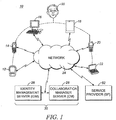
- reference numeral 10 in FIG. 1 generally identifies an apparatus for multi-factor authentication for a user 50 among a plurality of his or her communication devices, such as, by way of non-limiting example, a personal digital assistant 12, a smartphone 14, a desktop computer 16, a tablet 18, a land mobile radio (LMR) 20, and a laptop computer 22.
- LMR land mobile radio
- Each of these communication devices has one or more network interfaces, which may include one or more radio frequency (RF) transceivers operatively connected to a network 24, for example, the Internet, preferably over a bi-directional wireless link, such as Wi-Fi, which is an open wireless standard for transmission of digital voice and data.
- RF radio frequency
- the network 24 need not be a single network as illustrated, but could comprise a plurality of networks interconnected by forwarding equipment.
- the communication devices 12, 14, 16, 18, 20 and 22 not only communicate over the network 24 with a service provider (SP) 52, but can also wirelessly communicate with one another, for example, via Bluetooth ® , which is another open wireless standard for transmission of digital voice and data between devices.
- SP service provider
- all of the user's communication devices 12, 14, 16, 18, 20 and 22 can communicate directly with each other. In another embodiment, some of the user's communication devices may have to communicate with each other via one or more of the user's other communication devices. In one embodiment, all of the user's communication devices have the same wireless interface, such as Bluetooth ® . In another embodiment, some of the user's communication devices have one wireless interface, such as Bluetooth ® ; others of the communication devices have another wireless interface, such as Wi-Fi; and still others of the communication devices have both, or other interfaces.
- the apparatus 10 includes a server 30, which comprises either a single identity management server (IdM) 26, or the IdM 26 in combination with a collaboration manager server (CM) 28.
- the server 30 is operatively connected to the network 24 over a bi-directional wireline or wireless link and interacts with one or more of the devices 12, 14, 16, 18, 20 and 22, as described in detail below.
- Each server comprises one or more processes running on one or more computers. More particularly, each of the server 30 and the mobile devices 12, 14, 16, 18, 20 and 22 includes a processor, such as one or more microprocessors, microcontrollers, digital signal processors (DSPs), combinations thereof or such other devices known to those having ordinary skill in the art.
- DSPs digital signal processors
- the particular operations/functions of the processor, and respectively thus of the server and communication devices, is determined by an execution of software instructions and routines that are stored in a respective at least one memory device associated with the processor, such as random access memory (RAM), dynamic random access memory (DRAM), and/or read only memory (ROM) or equivalents thereof, that store data and programs that may be executed by the corresponding processor.
- RAM random access memory
- DRAM dynamic random access memory
- ROM read only memory
- each of the IdM and the CM includes a processor whose particular operations/functions, and respectively thus of the server, is determined by an execution of software instructions and routines that are stored in a respective at least one memory device associated with the processor.
- the functionality described herein as being performed by the server(s) and mobile devices is implemented with or in software programs and instructions stored in the respective at least one memory device of the server(s) and mobile devices and executed by the associated processor of the server(s) and mobile devices.
- each of these devices 12, 14, 16, 18, 20 and 22 typically has different hardware specifications and often are accessed with different authentication factors.
- the laptop computer 22 has a real keyboard to enter a user name and password, but may not have a biometric scanner, or some other means of factor authentication.
- the tablet 18 might have a biometric scanner, but not a slot/socket for receiving a security card, a dongle, or hardware token, or some other means of factor authentication.
- the desktop computer 16 may be the only device configured to enter multiple factors, but the user 50 may be unwilling to repeat a factor previously entered on another device. Some SPs 52 require multi-factor authentication to access their services.
- any one of the aforementioned devices 12, 14, 16, 18, 20 and 22 is depicted, and hereinafter referred to, as device 1, and any other of the aforementioned devices 12, 14, 16, 18, 20 and 22 is depicted, and hereinafter referred to, as device 2.
- the devices 1 and 2 may be of different types, or may be of the same type, e.g., both devices 1 and 2 may be smartphones.
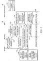
- the IdM 26 and the SP 52 are also shown, across the top of each chart, e.g., a host for hosting services and applications that are provided over the network 24. The timed sequence in which various actions are performed is shown as one proceeds down away from the top of the chart.
- the SP 52 requires multi-factor authentication (box 100) to access its services.
- the user 50 of the device 1 first establishes a secure connection or "pairing" with the device (see message 102). If Bluetooth ® is employed, then pairing occurs when two Bluetooth ® devices agree to communicate with each other and establish the secure connection. In some cases, Bluetooth ® can provide the needed security association, and, in other cases, a higher communication layer can provide the needed security association. In some cases, a shared secret, also sometimes referred to as a passkey or a personal identification number (PIN), is exchanged between the two devices 1 and 2.
- PIN personal identification number
- the devices 1 and 2 can each derive a shared secret without directly exchanging the value of the shared secret between each other, such as is provided by the well known Diffie-Hellman algorithm.
- a passkey is a code shared by both devices 1 and 2, which proves that both devices have agreed to pair with each other.
- the security association used for pairing is established through the use of certificate-based authentication.
- the paired devices exchange digital certificates, such as standard X.509 certificates, public key cryptographic methods, such as those described by the TLS standard, are used to establish the necessary security association.
- the device 1 sends a collaboration request (box 104) to device 2.
- the user of device 2 authenticates himself or herself to the IdM 26 by using a first authentication factor 1 (box 106).
- the IdM 26 generates (see box 108) a single factor identity token (as defined below) and a collaboration credential (as also defined below), and then sends the single factor identity token to the device 2 (see message 110), and also sends the collaboration credential to the device 2 (see message 112).
- Messages 110 and 112 need not be separate independent transmissions, but could be sent simultaneously in a single transmission.
- the collaboration credential is then sent by the device 2 to the device 1 (message 114), which initially requested collaboration in message 104. In this way, the collaboration credential is shared by the IdM 26 and the devices 1 and 2.
- the collaboration credential is a Kerberos data structure or ticket containing, by way of non-limiting example, one or more of a user identification, a session identification, a collaboration device identification(s), other collaboration device description(s), an expiration time, and other usage constraints.
- the collaboration credential is an OAuth token, a SAML token, a JSON Web Token (JWT), or another type of identity token.
- the collaboration credential is a data structure that contains information used to bind multiple devices to a single user 50, or to bind multiple devices to a single purpose, or to bind the user 50 to a device, or to bind a device to one or more other devices, or to bind at least one device to a user group.
- the collaboration credential may contain a user identification, and one or more device identifications.
- the collaboration credential can include constraints indicating under what circumstances collaboration can occur, such as requirements on devices with which collaboration can occur, and identifying when collaboration can occur.
- the collaboration credential can also contain an indication of how user authentication was performed on the device to which the collaboration credential is being issued, including an indication of the type of authentication factor used, or an indication or identification of the single factor identity token issued as a result of the user authentication, or a session identification associated with the user authentication. Because constraints may be included in the collaboration credential, each device 1 and 2 now knows which of the plurality of communication devices are permitted to collaborate with them, and also knows the conditions under which such collaboration is permitted to be conducted.
- the device 1 might be instructed by the collaboration credential to collaborate with only one other device, such as the user's desktop computer 16, or to only collaborate with another device for a set period of time, or to only collaborate using certain applications hosted by the SP 52, or to collaborate only with communication devices with which it is able to perform certificate-based authentication, etc.
- the data contained in the collaboration credential may have been supplied by the user 50, or by the device 1, during identification/authentication as described above, or may have been entered into a database of the server 30 beforehand.
- the data provided by the user 50 may be used in conjunction with data in the aforementioned database to determine the conditions under which collaboration is permitted.
- the user 50 of the device 1 may now request a multi-factor identity token 1in order to access a service from the SP 52. Even though the user 50 is on a different device, i.e., device 1, the user 50 of the device 1 may use a different second authentication factor 2 to perform user authentication. Hence, the user of device1 now authenticates himself or herself to the IdM 26 by using the second authentication factor 2 and forwards the collaboration credential to the IdM 26(message 118). Although message 118 is shown as a single transmission, it could be equivalently accomplished with a sequence of transmissions between the IdM 26 and the device 1.
- the IdM 26 determines from the collaboration credential that this is the same user 50 who has previously authenticated himself or herself with the message(s) 118 by using a separate authentication factor, and generates (see box 120) multi-factor identity tokens (as defined below). More particularly, the IdM 26 sends a first multi-factor identity token 1 to the device 1 (see message 122), and also sends a second multi-factor identity token 2 to the device 2 (see message 124). Now, the user 50 of the device 1 can request access to the SP 52 by using the multi-factor identity token 1 (see message 126).
- FIG. 3 describes a variant architecture in which, among other things, the single factor identity token 1 is generated and sent to its respective device 1 before the devices 1 and 2 are paired.
- the SP 52 requires multi-factor authentication (box 100) to access its services.
- the user 50 of device authenticates himself or herself to the IdM 26 by using a first authentication factor 1 (box 128).
- the IdM 26 generates (see box 130) a single factor identity token (as defined below) and a collaboration credential (as also defined below), and then sends the single factor identity token 1 and the collaboration credential to the device 1 (see message 132) in a single transmission, although, as noted above, these could be separate independent transmissions.
- the devices 1 and 2 are paired (see message 134), as described above.
- Either device 1 or 2 may implicitly or explicitly request a collaboration credential (as defined below) with the other (message 136), whereupon the collaboration credential is transferred between the devices 1 and 2 (message 138).
- the user 50 of the device 2 now authenticates himself or herself to the IdM 26 by using a second authentication factor 2 and the collaboration credential is forwarded to the IdM 26 (message 140).
- Message 140 can be one or more transmissions.
- the IdM 26 In response, the IdM 26 generates (box 142) a multi-factor identity token (as defined below), and then sends the multi-factor identity token to the device 2 (message 144), and also sends the same multi-factor identity token to the device 1 (see message 146). Now, the user 50 of either device 1 or 2 can request access to the SP 52 using the multi-factor identity token (message 148).
- a multi-factor identity token as defined below
- FIG. 4 describes a variant architecture in which, among other things, the single factor identity tokens 1 and 2 are both initially generated and sent to the respective devices 1 and 2, after which the devices 1 and 2 are paired.
- the SP 52 requires multi-factor authentication (box 100) to access its services.
- the user 50 of device authenticates himself or herself to the IdM 26 by using a first authentication factor 1 (box 150).
- the IdM 26 generates (see box 152) a single factor identity token 1 (as defined below) and a collaboration credential (as also defined below), and then sends the single factor identity token 1 and the collaboration credential to the device 1 (see message 154) in a single transmission, although, as noted above, these could be separate independent transmissions.
- the user 50 of the device 2 now authenticates himself or herself to the IdM 26 by using a second authentication factor 2 (message 156).
- the IdM 26 does not know if the user intended to perform multi-factor authentication.
- the IdM 26 generates (see box 158) another single factor identity token 2 (as defined below) and another collaboration credential (as also defined below), and then sends the single factor identity token 2 and the collaboration credential to the device 2 (see message 160) in a single transmission, although, as noted above, these could be separate independent transmissions.
- the devices are paired (see message 162), as described above.
- Either device 1 or 2 may implicitly or explicitly request a collaboration credential (as defined below) with the other (message 164), whereupon the collaboration credential is transferred between the devices 1 and 2 (message 166), and then to the IdM 26 (message 168).
- the message 168 may contain at least one of the single factor identity token 2 issued to the device 2, the collaboration credential issued to the device 1, the collaboration credential issued to the device 2, or a reference to any combination of these tokens/credentials.
- the IdM 26 now knows that multi-factor authentication is being requested and then generates (box 170) a multi-factor identity token (as defined below), and then sends the multi-factor identity token to the device 2 (message 172), and also sends the same multi-factor identity token to the device 1 (see message 174). Now, the user 50 of either device 1 or 2 can request access to the SP 52 using the multi-factor identity token (message 176).
- collaboration credential is the same for all the devices. It is also contemplated that different collaboration credentials could be used for different sets of the devices. For example, one collaboration credential can be used by the device 1 to enable single sign-on (SSO) collaboration with other devices, and a separate collaboration credential can be used by device 2 to collaborate with other devices. Alternatively, one collaboration credential may be constrained to a specific application, a set of applications, a device type, a device assurance level, a collaborative network type (personal area network, vehicular area network, etc.), or to any other device, user, or network attribute. The collaboration credential may contain a data field in which one, or more, or all, of the multiple authentication factors are identified. although this is not necessary if the collaboration credential contained an indication of the first single factor identity token, because the IdM 26 could use that information to look up the first single factor identity token and determine the authentication factor that was used.
- identity token is used to refer to a syntactical structure that communicates information about the user 50.
- Types of information often communicated within an identity token include: a unique identifier for the user 50, a unique identifier of the server 30 which issued the identity token, an expiration time after which the identity token may no longer be used, the time at which the identity token was issued, and a primary authentication context reference specifying the time at which the user authenticated themselves in order to obtain the identity token and the method of authentication they used (passwords and RSA passcodes are two examples).
- Identity tokens may also contain other relevant attributes about the user 50, such as his or her agency of employment, roles within his or her agency, special skills, or identifying facial attributes. This list is meant to be exemplary of a typical identity token, and non-binding, as many other attributes might be included as well. Identity tokens may be either digitally signed by the token issuer, or may alternatively require a secure connection between the consumer of the identity token (often referred to as the relying party, service provider, or resource server) and the identity token issuer.
- Identity tokens are also known by other names within industry and standards. In the SAML 2.0 protocol, identity tokens may be referred to as SAML assertions, or simply, identity assertions. In OAuth, identity tokens are referred to as access tokens, and in OpenID Connect, identity tokens may be referred to as id_tokens. Other identity tokens are intended for usage strictly between the user and the token issuing server, and these are often referred to as session tokens. In OAuth, a refresh token could be thought of as but one example of a session token.
- a includes ... a
- or “contains ... a” does not, without more constraints, preclude the existence of additional identical elements in the process, method, article, or apparatus that comprises, has, includes, or contains the element.
- the terms “a” and “an” are defined as one or more unless explicitly stated otherwise herein.
- the terms “substantially,” “essentially,” “approximately,” “about,” or any other version thereof, are defined as being close to as understood by one of ordinary skill in the art, and in one non-limiting embodiment the term is defined to be within 10%, in another embodiment within 5%, in another embodiment within 1%, and in another embodiment within 0.5%.
- the term “coupled” as used herein is defined as connected, although not necessarily directly and not necessarily mechanically.
- a device or structure that is “configured” in a certain way is configured in at least that way, but may also be configured in ways that are not listed.
- processors such as microprocessors, digital signal processors, customized processors, and field programmable gate arrays (FPGAs), and unique stored program instructions (including both software and firmware) that control the one or more processors to implement, in conjunction with certain non-processor circuits, some, most, or all of the functions of the method and/or apparatus described herein.
- processors or “processing devices”
- FPGAs field programmable gate arrays
- unique stored program instructions including both software and firmware
- an embodiment can be implemented as a computer-readable storage medium having computer readable code stored thereon for programming a computer (e.g., comprising a processor) to perform a method as described and claimed herein.
- Examples of such computer-readable storage mediums include, but are not limited to, a hard disk, a CD-ROM, an optical storage device, a magnetic storage device, a ROM (Read Only Memory), a PROM (Programmable Read Only Memory), an EPROM (Erasable Programmable Read Only Memory), an EEPROM (Electrically Erasable Programmable Read Only Memory) and a Flash memory.
Description
- The present disclosure relates generally to an apparatus for, and a method of, multi-factor authentication among a plurality of collaborating communication devices.
- Multi-factor authentication is an approach to security authentication, which requires that an on-line user of a network provide more than one form of verification in order to prove his or her identity and allow access to the network. Multi-factor authentication takes advantage of a combination of several factors of authentication. Three major factors include: verification by something the user knows, such as a password, or a personal identification number (PIN); something the user has, such as a smart card, a security fob, a hardware or virtual token, a USB dongle, or a digital certificate; and something the user is, such as a biometric characteristic, e.g., a fingerprint, a facial image, a retinal pattern, a voice print, etc. Due to its increased complexity, a multi-factor authentication is harder to compromise than a single factor authentication.
- As advantageous as these multi-factor authentication techniques have been, multi-factor authentication is not supported when a user performs authentication by using a first authentication factor on a first communication device, and performs authentication by using a second authentication factor on a second collaborating communication device. The term "collaborating" or "collaboration" refers to a type of working cooperation among the communication devices, whereby a user can securely leverage the capabilities of a second communication device from a first communication device; for example, the user can sign-on, or login, to a first service from a first communication device, and leverage a set of enhanced identity management procedures to securely access the first service, as well as other services, from the first communication device, as well as from other communication devices, without needing to perform additional manual sign-on procedures. By way of example, a user may be checking his or her email, or using some other application hosted by a service provider, on a personal digital assistant or a smartphone, and then, for whatever reason, may subsequently wish to check his or her email, or even run a different application, e.g., banking services, shopping services, etc., on his or her laptop computer or a desktop computer. Thereafter, the user may wish to check his or her email, or even run a different application, on his or her tablet. The user may, in case of emergency, subsequently wish to run an application, on his or her land mobile radio (LMR). Security Assertion Markup Language (SAML) and Web Authorization Protocol (OAuth) are examples of open standards for exchanging authentication and authorization data between such multiple applications on a single communication device, but not across multiple devices.
- However, each of these devices typically has different hardware specifications and often are accessed with different authentication factors. One device might have a real or virtual keyboard to enter a user name and password, but not a biometric scanner, or some other means of factor authentication. Another device might have a biometric scanner, but not a slot/socket for receiving a security card, a dongle, or hardware token, or some other means of factor authentication. Some devices may be configured to enter multiple factors, but the user may be unwilling to repeat a factor previously entered on another device. Some service providers require multi-factor authentication to access their services.
- Hocking et al., "A distributed and cooperative user authentication framework", Proceedings of the Sixth International Conference on Information Assurance and Security, IEEE, 2010, pp.304-310, discloses a system and a method for combining authentication mechanisms used by different devices operated by same user.
- At present, there is no multi-factor authentication process that supports the user across a plurality of collaborating communication devices, whereby the user performs authentication by using a first authentication factor on a first device, and then performs authentication by using a second authentication factor on a second device, and whereby these authentication factors are bound together such that the network recognizes that multi-factor authentication has been performed. Accordingly, there is a need to enable multi-factor authentication across a plurality of collaborating communication devices for greater network security.
- The accompanying figures, where like reference numerals refer to identical or functionally similar elements throughout the separate views, together with the detailed description below, are incorporated in and form part of the specification, and serve to further illustrate embodiments of concepts that include the claimed invention, and explain various principles and advantages of those embodiments.
-
FIG. 1 is a schematic view of an apparatus for multi-factor authentication among a plurality of collaborating communication devices in accordance with the present disclosure. -
FIG. 2 is a message sequence chart depicting steps performed in a method of multi-factor authentication among a plurality of collaborating communication devices in accordance with one embodiment of the present disclosure. -
FIG. 3 is a message sequence chart depicting steps performed in a method of multi-factor authentication among a plurality of collaborating communication devices in accordance with another embodiment of the present disclosure. -
FIG. 4 is a message sequence chart depicting steps performed in a method of multi-factor authentication among a plurality of collaborating communication devices in accordance with another embodiment of the present disclosure. - Skilled artisans will appreciate that elements in the figures are illustrated for simplicity and clarity and have not necessarily been drawn to scale. For example, the dimensions and locations of some of the elements in the figures may be exaggerated relative to other elements to help to improve understanding of embodiments of the present invention.
- The apparatus and method components have been represented where appropriate by conventional symbols in the drawings, showing only those specific details that are pertinent to understanding the embodiments of the present invention so as not to obscure the disclosure with details that will be readily apparent to those of ordinary skill in the art having the benefit of the description herein.
- One aspect of this disclosure relates to an apparatus for multi-factor authentication among a plurality of collaborating communication devices. The apparatus includes a server operative for authenticating a user who uses a first authentication factor on a first of the communication devices, and a second authentication factor on a second of the communication devices. The server is further operative for sharing a collaboration credential (as defined below) among the communication devices to enable the communication devices to collaborate with each other. The server is still further operative for binding both of the authentication factors, and for issuing a multi-factor identification token to each to the communication devices, to support multi-factor authentication for the user across the plurality of communication devices.
- Advantageously, the collaboration credential can be generated by the server or by one of the communication devices. The term "sharing" is intended to mean a transmission of the collaboration credential among the server and the devices. For example, if the server generates the collaboration credential, then the collaboration credential is shared when it is received by one of the devices, and/or when it is sent to, and received by, another of the devices. Similarly, if one of the devices generates the collaboration credential, then the collaboration credential is shared when it is received by the server or another of the devices, and/or when it is sent by the other device to the server or the one device.
- A method, in accordance with another aspect of this disclosure, of multi-factor authentication among a plurality of communication devices, is performed by authenticating a user who uses a first authentication factor on a first of the communication devices, and who uses a second authentication factor on a second of the communication devices, by sharing a collaboration credential among the communication devices to enable the communication devices to collaborate with each other, by binding both of the authentication factors, and by issuing a multi-factor identification token to each of the communication devices, to support multi-factor authentication for the user across the plurality of communication devices.
- Turning now to the drawings,
reference numeral 10 inFIG. 1 generally identifies an apparatus for multi-factor authentication for auser 50 among a plurality of his or her communication devices, such as, by way of non-limiting example, a personaldigital assistant 12, asmartphone 14, adesktop computer 16, atablet 18, a land mobile radio (LMR) 20, and alaptop computer 22. Other communication devices, and other device types, that are different from those illustrated are also contemplated by the present disclosure. Each of these communication devices has one or more network interfaces, which may include one or more radio frequency (RF) transceivers operatively connected to anetwork 24, for example, the Internet, preferably over a bi-directional wireless link, such as Wi-Fi, which is an open wireless standard for transmission of digital voice and data. Thenetwork 24 need not be a single network as illustrated, but could comprise a plurality of networks interconnected by forwarding equipment. Thecommunication devices network 24 with a service provider (SP) 52, but can also wirelessly communicate with one another, for example, via Bluetooth®, which is another open wireless standard for transmission of digital voice and data between devices. - In one embodiment, all of the user's
communication devices - The
apparatus 10 includes aserver 30, which comprises either a single identity management server (IdM) 26, or the IdM 26 in combination with a collaboration manager server (CM) 28. Theserver 30 is operatively connected to thenetwork 24 over a bi-directional wireline or wireless link and interacts with one or more of thedevices server 30 and themobile devices server 30 is implement as both theIdM 26 and theCM 28, each of the IdM and the CM includes a processor whose particular operations/functions, and respectively thus of the server, is determined by an execution of software instructions and routines that are stored in a respective at least one memory device associated with the processor. Unless otherwise specified herein, the functionality described herein as being performed by the server(s) and mobile devices is implemented with or in software programs and instructions stored in the respective at least one memory device of the server(s) and mobile devices and executed by the associated processor of the server(s) and mobile devices. - As noted above, each of these
devices laptop computer 22 has a real keyboard to enter a user name and password, but may not have a biometric scanner, or some other means of factor authentication. Thetablet 18 might have a biometric scanner, but not a slot/socket for receiving a security card, a dongle, or hardware token, or some other means of factor authentication. Thedesktop computer 16 may be the only device configured to enter multiple factors, but theuser 50 may be unwilling to repeat a factor previously entered on another device. SomeSPs 52 require multi-factor authentication to access their services. - Turning now to the message sequence charts of
FIGs. 2-4 , across the top of each chart, any one of theaforementioned devices device 1, and any other of theaforementioned devices device 2. It will be appreciated that thedevices devices SP 52, e.g., a host for hosting services and applications that are provided over thenetwork 24. The timed sequence in which various actions are performed is shown as one proceeds down away from the top of the chart. - In
FIG. 2 , theSP 52 requires multi-factor authentication (box 100) to access its services. As shown, theuser 50 of thedevice 1 first establishes a secure connection or "pairing" with the device (see message 102). If Bluetooth® is employed, then pairing occurs when two Bluetooth® devices agree to communicate with each other and establish the secure connection. In some cases, Bluetooth® can provide the needed security association, and, in other cases, a higher communication layer can provide the needed security association. In some cases, a shared secret, also sometimes referred to as a passkey or a personal identification number (PIN), is exchanged between the twodevices devices devices - It will be appreciated by those skilled in the art that once a security association exists between devices, data can be sent securely between the
devices - Once paired, the
device 1 sends a collaboration request (box 104) todevice 2. Then, the user ofdevice 2, for example, authenticates himself or herself to theIdM 26 by using a first authentication factor 1 (box 106). In response, theIdM 26 generates (see box 108) a single factor identity token (as defined below) and a collaboration credential (as also defined below), and then sends the single factor identity token to the device 2 (see message 110), and also sends the collaboration credential to the device 2 (see message 112).Messages device 2 to the device 1 (message 114), which initially requested collaboration inmessage 104. In this way, the collaboration credential is shared by theIdM 26 and thedevices - In one embodiment, the collaboration credential is a Kerberos data structure or ticket containing, by way of non-limiting example, one or more of a user identification, a session identification, a collaboration device identification(s), other collaboration device description(s), an expiration time, and other usage constraints. In another embodiment, the collaboration credential is an OAuth token, a SAML token, a JSON Web Token (JWT), or another type of identity token. The collaboration credential is a data structure that contains information used to bind multiple devices to a
single user 50, or to bind multiple devices to a single purpose, or to bind theuser 50 to a device, or to bind a device to one or more other devices, or to bind at least one device to a user group. - As such, the collaboration credential may contain a user identification, and one or more device identifications. The collaboration credential can include constraints indicating under what circumstances collaboration can occur, such as requirements on devices with which collaboration can occur, and identifying when collaboration can occur. Further, the collaboration credential can also contain an indication of how user authentication was performed on the device to which the collaboration credential is being issued, including an indication of the type of authentication factor used, or an indication or identification of the single factor identity token issued as a result of the user authentication, or a session identification associated with the user authentication. Because constraints may be included in the collaboration credential, each
device - By way of non-limiting example, the
device 1 might be instructed by the collaboration credential to collaborate with only one other device, such as the user'sdesktop computer 16, or to only collaborate with another device for a set period of time, or to only collaborate using certain applications hosted by theSP 52, or to collaborate only with communication devices with which it is able to perform certificate-based authentication, etc. The data contained in the collaboration credential may have been supplied by theuser 50, or by thedevice 1, during identification/authentication as described above, or may have been entered into a database of theserver 30 beforehand. In one embodiment, the data provided by theuser 50 may be used in conjunction with data in the aforementioned database to determine the conditions under which collaboration is permitted. - Next, the
user 50 of thedevice 1 may now request a multi-factor identity token 1in order to access a service from theSP 52. Even though theuser 50 is on a different device, i.e.,device 1, theuser 50 of thedevice 1 may use a differentsecond authentication factor 2 to perform user authentication. Hence, the user of device1 now authenticates himself or herself to theIdM 26 by using thesecond authentication factor 2 and forwards the collaboration credential to the IdM 26(message 118). Althoughmessage 118 is shown as a single transmission, it could be equivalently accomplished with a sequence of transmissions between theIdM 26 and thedevice 1. In response, theIdM 26 determines from the collaboration credential that this is thesame user 50 who has previously authenticated himself or herself with the message(s) 118 by using a separate authentication factor, and generates (see box 120) multi-factor identity tokens (as defined below). More particularly, theIdM 26 sends a firstmulti-factor identity token 1 to the device 1 (see message 122), and also sends a secondmulti-factor identity token 2 to the device 2 (see message 124). Now, theuser 50 of thedevice 1 can request access to theSP 52 by using the multi-factor identity token 1 (see message 126). - As described in
FIG. 2 , thedevices factor identity token 1 is generated and sent to its respective device.FIG. 3 describes a variant architecture in which, among other things, the singlefactor identity token 1 is generated and sent to itsrespective device 1 before thedevices - In
FIG. 3 , as before, theSP 52 requires multi-factor authentication (box 100) to access its services. First, theuser 50 ofdevice 1, for example, authenticates himself or herself to theIdM 26 by using a first authentication factor 1 (box 128). In response, theIdM 26 generates (see box 130) a single factor identity token (as defined below) and a collaboration credential (as also defined below), and then sends the singlefactor identity token 1 and the collaboration credential to the device 1 (see message 132) in a single transmission, although, as noted above, these could be separate independent transmissions. - Next, the
devices device devices 1 and 2 (message 138). Next, theuser 50 of thedevice 2 now authenticates himself or herself to theIdM 26 by using asecond authentication factor 2 and the collaboration credential is forwarded to the IdM 26 (message 140).Message 140 can be one or more transmissions. In response, theIdM 26 generates (box 142) a multi-factor identity token (as defined below), and then sends the multi-factor identity token to the device 2 (message 144), and also sends the same multi-factor identity token to the device 1 (see message 146). Now, theuser 50 of eitherdevice SP 52 using the multi-factor identity token (message 148). -
FIG. 4 describes a variant architecture in which, among other things, the singlefactor identity tokens respective devices devices FIG. 4 , as before, theSP 52 requires multi-factor authentication (box 100) to access its services. - First, the
user 50 ofdevice 1, for example, authenticates himself or herself to theIdM 26 by using a first authentication factor 1 (box 150). In response, theIdM 26 generates (see box 152) a single factor identity token 1 (as defined below) and a collaboration credential (as also defined below), and then sends the singlefactor identity token 1 and the collaboration credential to the device 1 (see message 154) in a single transmission, although, as noted above, these could be separate independent transmissions. - Next, the
user 50 of thedevice 2 now authenticates himself or herself to theIdM 26 by using a second authentication factor 2 (message 156). At this point, theIdM 26 does not know if the user intended to perform multi-factor authentication. Hence, theIdM 26 generates (see box 158) another single factor identity token 2 (as defined below) and another collaboration credential (as also defined below), and then sends the singlefactor identity token 2 and the collaboration credential to the device 2 (see message 160) in a single transmission, although, as noted above, these could be separate independent transmissions. - Next, the devices are paired (see message 162), as described above. Either
device devices 1 and 2 (message 166), and then to the IdM 26 (message 168). In a variant of this embodiment, themessage 168 may contain at least one of the singlefactor identity token 2 issued to thedevice 2, the collaboration credential issued to thedevice 1, the collaboration credential issued to thedevice 2, or a reference to any combination of these tokens/credentials. - In response, the
IdM 26 now knows that multi-factor authentication is being requested and then generates (box 170) a multi-factor identity token (as defined below), and then sends the multi-factor identity token to the device 2 (message 172), and also sends the same multi-factor identity token to the device 1 (see message 174). Now, theuser 50 of eitherdevice SP 52 using the multi-factor identity token (message 176). - As described so far, the collaboration credential is the same for all the devices. It is also contemplated that different collaboration credentials could be used for different sets of the devices. For example, one collaboration credential can be used by the
device 1 to enable single sign-on (SSO) collaboration with other devices, and a separate collaboration credential can be used bydevice 2 to collaborate with other devices. Alternatively, one collaboration credential may be constrained to a specific application, a set of applications, a device type, a device assurance level, a collaborative network type (personal area network, vehicular area network, etc.), or to any other device, user, or network attribute. The collaboration credential may contain a data field in which one, or more, or all, of the multiple authentication factors are identified. although this is not necessary if the collaboration credential contained an indication of the first single factor identity token, because theIdM 26 could use that information to look up the first single factor identity token and determine the authentication factor that was used. - Throughout this specification, the term "identity token" is used to refer to a syntactical structure that communicates information about the
user 50. Types of information often communicated within an identity token include: a unique identifier for theuser 50, a unique identifier of theserver 30 which issued the identity token, an expiration time after which the identity token may no longer be used, the time at which the identity token was issued, and a primary authentication context reference specifying the time at which the user authenticated themselves in order to obtain the identity token and the method of authentication they used (passwords and RSA passcodes are two examples). - Identity tokens may also contain other relevant attributes about the
user 50, such as his or her agency of employment, roles within his or her agency, special skills, or identifying facial attributes. This list is meant to be exemplary of a typical identity token, and non-binding, as many other attributes might be included as well. Identity tokens may be either digitally signed by the token issuer, or may alternatively require a secure connection between the consumer of the identity token (often referred to as the relying party, service provider, or resource server) and the identity token issuer. - Identity tokens are also known by other names within industry and standards. In the SAML 2.0 protocol, identity tokens may be referred to as SAML assertions, or simply, identity assertions. In OAuth, identity tokens are referred to as access tokens, and in OpenID Connect, identity tokens may be referred to as id_tokens. Other identity tokens are intended for usage strictly between the user and the token issuing server, and these are often referred to as session tokens. In OAuth, a refresh token could be thought of as but one example of a session token.
- In the foregoing specification, specific embodiments have been described. However, one of ordinary skill in the art appreciates that various modifications and changes can be made without departing from the scope of the invention as set forth in the claims below. For example, although the TLS protocol has been described and illustrated herein, other cryptographic protocols, such as Internet Protocol Security (IPsec), Secure Sockets Layer (SSL), Secure Shell (SSH), and like cryptographic protocols that provide communication security over the Internet, could be employed. Accordingly, the specification and figures are to be regarded in an illustrative rather than a restrictive sense, and all such modifications are intended to be included within the scope of present teachings.
- The benefits, advantages, solutions to problems, and any element(s) that may cause any benefit, advantage, or solution to occur or become more pronounced are not to be construed as a critical, required, or essential features or elements of any or all the claims. The invention is defined solely by the appended claims including any amendments made during the pendency of this application and all equivalents of those claims as issued.
- Moreover in this document, relational terms such as first and second, top and bottom, and the like may be used solely to distinguish one entity or action from another entity or action without necessarily requiring or implying any actual such relationship or order between such entities or actions. The terms "comprises," "comprising," "has," "having," "includes," "including," "contains," "containing," or any other variation thereof, are intended to cover a non-exclusive inclusion, such that a process, method, article, or apparatus that comprises, has, includes, contains a list of elements does not include only those elements, but may include other elements not expressly listed or inherent to such process, method, article, or apparatus. An element proceeded by "comprises ... a," "has ... a," "includes ... a," or "contains ... a," does not, without more constraints, preclude the existence of additional identical elements in the process, method, article, or apparatus that comprises, has, includes, or contains the element. The terms "a" and "an" are defined as one or more unless explicitly stated otherwise herein. The terms "substantially," "essentially," "approximately," "about," or any other version thereof, are defined as being close to as understood by one of ordinary skill in the art, and in one non-limiting embodiment the term is defined to be within 10%, in another embodiment within 5%, in another embodiment within 1%, and in another embodiment within 0.5%. The term "coupled" as used herein is defined as connected, although not necessarily directly and not necessarily mechanically. A device or structure that is "configured" in a certain way is configured in at least that way, but may also be configured in ways that are not listed.
- It will be appreciated that some embodiments may be comprised of one or more generic or specialized processors (or "processing devices") such as microprocessors, digital signal processors, customized processors, and field programmable gate arrays (FPGAs), and unique stored program instructions (including both software and firmware) that control the one or more processors to implement, in conjunction with certain non-processor circuits, some, most, or all of the functions of the method and/or apparatus described herein. Alternatively, some or all functions could be implemented by a state machine that has no stored program instructions, or in one or more application specific integrated circuits (ASICs), in which each function or some combinations of certain of the functions are implemented as custom logic. Of course, a combination of the two approaches could be used.
- Moreover, an embodiment can be implemented as a computer-readable storage medium having computer readable code stored thereon for programming a computer (e.g., comprising a processor) to perform a method as described and claimed herein. Examples of such computer-readable storage mediums include, but are not limited to, a hard disk, a CD-ROM, an optical storage device, a magnetic storage device, a ROM (Read Only Memory), a PROM (Programmable Read Only Memory), an EPROM (Erasable Programmable Read Only Memory), an EEPROM (Electrically Erasable Programmable Read Only Memory) and a Flash memory. Further, it is expected that one of ordinary skill, notwithstanding possibly significant effort and many design choices motivated by, for example, available time, current technology, and economic considerations, when guided by the concepts and principles disclosed herein, will be readily capable of generating such software instructions and programs and ICs with minimal experimentation.
- The Abstract of the Disclosure is provided to allow the reader to quickly ascertain the nature of the technical disclosure. It is submitted with the understanding that it will not be used to interpret or limit the scope or meaning of the claims. In addition, in the foregoing Detailed Description, it can be seen that various features are grouped together in various embodiments for the purpose of streamlining the disclosure. This method of disclosure is not to be interpreted as reflecting an intention that the claimed embodiments require more features than are expressly recited in each claim. Rather, as the following claims reflect, inventive subject matter lies in less than all features of a single disclosed embodiment. Thus, the following claims are hereby incorporated into the Detailed Description, with each claim standing on its own as a separately claimed subject matter.
Claims (15)
- An apparatus for multi-factor authentication among a plurality of communication devices, comprising:a server having a processor that is configured to:authenticate a user who uses a first authentication factor on a first of the communication devices, and who uses a second authentication factor on a second of the communication devices,transmit a collaboration credential (112) and a single factor identity token (110) to the first communication device to enable the communication devices to collaborate with each other, wherein the collaboration credential gives permission for the first and the second devices to share services among devices;receive (118) the collaboration credential from the second of the communication devices along with the second authentication factor, andbind both of the authentication factors, and issue (122, 124) a multi-factor identification token to each of the communication devices, to support multi-factor authentication for the user across the plurality of communication devices to request (126) access to a service.
- The apparatus of claim 1, wherein one of the server and one of the communication devices is operative for generating (108) the collaboration credential.
- The apparatus of claim 1, wherein the processor is configured to send the multi-factor identification token to each of the communication devices after the collaboration credential has been shared (114) by the communication devices.
- The apparatus of claim 3, wherein the multi-factor identification token issued to each of the communication devices is the same.
- The apparatus of claim 3, wherein the multi-factor identification token issued to each of the communication devices is different.
- The apparatus of claim 1, wherein the processor is configured to issue and send (110) a single factor identity token to one of the communication devices.
- The apparatus of claim 1, wherein the processor is configured to issue and send (154, 160) single factor identity tokens to each of the communication devices.
- The apparatus of claim 1, wherein the processor is configured to configure the collaboration credential as a data structure comprising at least one of an identification of the user, an identification of the first communication device, an identification of which of the plurality of other communication devices are permitted to collaborate with the first communication device, an identification of the conditions under which the collaboration is permitted to be conducted, and an identification of the authentication factors.
- A method of multi-factor authentication among a plurality of communication devices, comprising:authenticating a user who uses a first authentication factor on a first of the communication devices, and who uses a second authentication factor on a second of the communication devices,transmitting a collaboration credential (112) and a single factor identity token (110) to the first communication device to enable the communication devices to collaborate with each other, wherein the collaboration credential gives permission for the first and the second devices to share services among devices,receiving (118) the collaboration credential from the second of the communication devices along with the second authentication factor,binding both of the authentication factors, andissuing (122, 124) a multi-factor identification token to each of the communication devices, to support multi-factor authentication for the user across the plurality of communication devices to request access to a service.
- The method of claim 9, further comprising the step of generating the collaboration credential with one of the server and one of the communication devices.
- The method of claim 9, further comprising the step of sending the multi-factor identification token to each of the communication devices after the collaboration credential has been shared (114) by the communication devices.
- The method of claim 11, further comprising the steps of sending the same multi-factor identification token to each of the communication devices.
- The method of claim 11, further comprising the step of sending different multi-factor identification tokens to each of the communication devices.
- The method of claim 11, further comprising the step of issuing and sending (154, 160) single factor identity tokens to each of the communication devices.
- The method of claim 9, further comprising the step of configuring the collaboration credential as a data structure comprising at least one of an identification of the user, an identification of the first communication device, an identification of which of the plurality of other communication devices are permitted to collaborate with the first communication device, an identification of the conditions under which the collaboration is permitted to be conducted, and an identification of the authentication factors.
Applications Claiming Priority (2)
| Application Number | Priority Date | Filing Date | Title |
|---|---|---|---|
| US13/728,797 US8806205B2 (en) | 2012-12-27 | 2012-12-27 | Apparatus for and method of multi-factor authentication among collaborating communication devices |
| PCT/US2013/071887 WO2014105343A1 (en) | 2012-12-27 | 2013-11-26 | Apparatus for and method of multi-factor authentication among collaborating communication devices |
Publications (2)
| Publication Number | Publication Date |
|---|---|
| EP2939387A1 EP2939387A1 (en) | 2015-11-04 |
| EP2939387B1 true EP2939387B1 (en) | 2017-03-29 |
Family
ID=49765699
Family Applications (1)
| Application Number | Title | Priority Date | Filing Date |
|---|---|---|---|
| EP13805687.4A Revoked EP2939387B1 (en) | 2012-12-27 | 2013-11-26 | Apparatus for and method of multi-factor authentication among collaborating communication devices |
Country Status (5)
| Country | Link |
|---|---|
| US (1) | US8806205B2 (en) |
| EP (1) | EP2939387B1 (en) |
| AU (1) | AU2013368375B2 (en) |
| CA (1) | CA2896681C (en) |
| WO (1) | WO2014105343A1 (en) |
Families Citing this family (55)
| Publication number | Priority date | Publication date | Assignee | Title |
|---|---|---|---|---|
| US9253168B2 (en) * | 2012-04-26 | 2016-02-02 | Fitbit, Inc. | Secure pairing of devices via pairing facilitator-intermediary device |
| US9571282B1 (en) | 2012-04-03 | 2017-02-14 | Google Inc. | Authentication on a computing device |
| US9038142B2 (en) * | 2013-02-05 | 2015-05-19 | Google Inc. | Authorization flow initiation using short-term wireless communication |
| US9992021B1 (en) | 2013-03-14 | 2018-06-05 | GoTenna, Inc. | System and method for private and point-to-point communication between computing devices |
| WO2014160853A1 (en) * | 2013-03-27 | 2014-10-02 | Interdigital Patent Holdings, Inc. | Seamless authentication across multiple entities |
| US9397989B1 (en) * | 2013-07-03 | 2016-07-19 | Amazon Technologies, Inc. | Bootstrapping user authentication on devices |
| US10148629B1 (en) | 2013-09-23 | 2018-12-04 | Amazon Technologies, Inc. | User-friendly multifactor authentication |
| WO2015130700A1 (en) * | 2014-02-26 | 2015-09-03 | Secureauth Corporation | Security object creation, validation, and assertion for single sign on authentication |
| US9710640B1 (en) | 2014-03-28 | 2017-07-18 | Amazon Technologies, Inc. | Bootstrapping authentication of second application via confirmation by first application |
| US9602501B1 (en) * | 2014-03-28 | 2017-03-21 | Amazon Technologies, Inc. | Bootstrapping user authentication |
| US10055567B2 (en) * | 2014-05-30 | 2018-08-21 | Apple Inc. | Proximity unlock and lock operations for electronic devices |
| US9942229B2 (en) * | 2014-10-03 | 2018-04-10 | Gopro, Inc. | Authenticating a limited input device via an authenticated application |
| US10255429B2 (en) | 2014-10-03 | 2019-04-09 | Wells Fargo Bank, N.A. | Setting an authorization level at enrollment |
| US9473490B2 (en) * | 2014-10-13 | 2016-10-18 | Wells Fargo Bank, N.A. | Bidirectional authentication |
| US10069814B2 (en) * | 2014-10-28 | 2018-09-04 | Ca, Inc. | Single sign on across multiple devices using a unique machine identification |
| US9648164B1 (en) | 2014-11-14 | 2017-05-09 | United Services Automobile Association (“USAA”) | System and method for processing high frequency callers |
| US10652739B1 (en) | 2014-11-14 | 2020-05-12 | United Services Automobile Association (Usaa) | Methods and systems for transferring call context |
| US9578023B2 (en) * | 2014-11-14 | 2017-02-21 | Motorola Solutions, Inc. | Identity assertion based on biometric information |
| US9659160B2 (en) | 2014-12-22 | 2017-05-23 | University Of South Florida | System and methods for authentication using multiple devices |
| US10367817B2 (en) | 2014-12-22 | 2019-07-30 | University Of South Florida | Systems and methods for challengeless coauthentication |
| US9380058B1 (en) | 2014-12-22 | 2016-06-28 | University Of South Florida | Systems and methods for anonymous authentication using multiple devices |
| WO2016115633A1 (en) * | 2015-01-21 | 2016-07-28 | FusionPipe Software Solutions Inc. | Enhanced security authentication methods, systems and media |
| KR20160109466A (en) * | 2015-03-11 | 2016-09-21 | 삼성전자주식회사 | Method for controlling dislay and an electronic device thereof |
| EP3284093B1 (en) | 2015-04-14 | 2021-08-04 | Cambou, Bertrand, F. | Memory circuits using a blocking state |
| WO2016182596A1 (en) | 2015-05-11 | 2016-11-17 | Cambou Bertrand F | Memory circuit using dynamic random access memory arrays |
| WO2016195736A1 (en) | 2015-06-02 | 2016-12-08 | Cambou Bertrand F | Memory circuit using resistive random access memory arrays in a secure element |
| US9614835B2 (en) | 2015-06-08 | 2017-04-04 | Microsoft Technology Licensing, Llc | Automatic provisioning of a device to access an account |
| US9882887B2 (en) | 2015-06-15 | 2018-01-30 | Airwatch Llc | Single sign-on for managed mobile devices |
| US11057364B2 (en) | 2015-06-15 | 2021-07-06 | Airwatch Llc | Single sign-on for managed mobile devices |
| US9961085B2 (en) * | 2015-06-15 | 2018-05-01 | Microsoft Technology Licensing, Llc | Linking identities in a network entity |
| US10944738B2 (en) | 2015-06-15 | 2021-03-09 | Airwatch, Llc. | Single sign-on for managed mobile devices using kerberos |
| US10171447B2 (en) | 2015-06-15 | 2019-01-01 | Airwatch Llc | Single sign-on for unmanaged mobile devices |
| US10812464B2 (en) | 2015-06-15 | 2020-10-20 | Airwatch Llc | Single sign-on for managed mobile devices |
| EP3320647B1 (en) | 2015-07-09 | 2020-11-18 | Nokia Technologies Oy | Token based authentication |
| US9967244B2 (en) | 2015-10-14 | 2018-05-08 | Microsoft Technology Licensing, Llc | Multi-factor user authentication framework using asymmetric key |
| US10187374B2 (en) * | 2015-10-29 | 2019-01-22 | Airwatch Llc | Multi-factor authentication for managed applications using single sign-on technology |
| US9866546B2 (en) * | 2015-10-29 | 2018-01-09 | Airwatch Llc | Selectively enabling multi-factor authentication for managed devices |
| US9787654B2 (en) * | 2015-10-29 | 2017-10-10 | Microsoft Technology Licensing, Llc | Resolving authenticating issues with a second device |
| US10740481B2 (en) | 2015-11-17 | 2020-08-11 | Idee Limited | Security systems and methods with identity management for access to restricted access locations |
| US9906520B2 (en) | 2015-12-02 | 2018-02-27 | International Business Machines Corporation | Multi-user authentication |
| US20170257363A1 (en) * | 2016-03-04 | 2017-09-07 | Secureauth Corporation | Secure mobile device two-factor authentication |
| US10038690B2 (en) | 2016-05-31 | 2018-07-31 | International Business Machines Corporation | Multifactor authentication processing using two or more devices |
| US10645079B2 (en) * | 2017-05-12 | 2020-05-05 | Bank Of America Corporation | Preventing unauthorized access to secured information systems using authentication tokens and multi-device authentication prompts |
| US11263300B2 (en) * | 2017-07-25 | 2022-03-01 | Samsung Electronics Co., Ltd. | Voice activation method for service provisioning on smart assistant devices |
| WO2019133769A1 (en) | 2017-12-29 | 2019-07-04 | Idee Limited | Single sign on (sso) using continuous authentication |
| US11095659B2 (en) * | 2018-05-30 | 2021-08-17 | Cisco Technology, Inc. | Personalized services based on confirmed proximity of user |
| US10791462B2 (en) * | 2018-10-15 | 2020-09-29 | Cisco Technology, Inc. | Flexible device onboarding via bootstrap keys |
| AU2018448130A1 (en) * | 2018-11-01 | 2021-06-24 | Fts Forest Technology Systems Ltd. | Multi-level authentication for shared device |
| US11469894B2 (en) * | 2019-05-20 | 2022-10-11 | Citrix Systems, Inc. | Computing system and methods providing session access based upon authentication token with different authentication credentials |
| US11336682B2 (en) | 2019-07-09 | 2022-05-17 | Nice Ltd. | System and method for generating and implementing a real-time multi-factor authentication policy across multiple channels |
| EP3767501A1 (en) * | 2019-07-18 | 2021-01-20 | Hewlett-Packard Development Company, L.P. | User authentication |
| WO2021247017A1 (en) * | 2020-06-03 | 2021-12-09 | Hewlett-Packard Development Company, L.P. | Shared security states |
| US20220138283A1 (en) * | 2020-10-30 | 2022-05-05 | Comcast Cable Communications, Llc | Secure Content Access |
| US11930014B2 (en) | 2021-09-29 | 2024-03-12 | Bank Of America Corporation | Information security using multi-factor authorization |
| US11762973B2 (en) | 2021-11-16 | 2023-09-19 | International Business Machines Corporation | Auditing of multi-factor authentication |
Citations (3)
| Publication number | Priority date | Publication date | Assignee | Title |
|---|---|---|---|---|
| US7788711B1 (en) | 2003-10-09 | 2010-08-31 | Oracle America, Inc. | Method and system for transferring identity assertion information between trusted partner sites in a network using artifacts |
| US8201231B2 (en) | 2007-02-21 | 2012-06-12 | Microsoft Corporation | Authenticated credential-based multi-tenant access to a service |
| US20120222102A1 (en) | 2011-02-24 | 2012-08-30 | Empire Technology Development Llc | Authentication using mobile devices |
Family Cites Families (93)
| Publication number | Priority date | Publication date | Assignee | Title |
|---|---|---|---|---|
| US6421768B1 (en) | 1999-05-04 | 2002-07-16 | First Data Corporation | Method and system for authentication and single sign on using cryptographically assured cookies in a distributed computer environment |
| WO2003009500A1 (en) | 2001-07-19 | 2003-01-30 | Cocomo Mb Communications, Inc. | Hub and probe system and method |
| US6760758B1 (en) | 1999-08-31 | 2004-07-06 | Qwest Communications International, Inc. | System and method for coordinating network access |
| DE10012057A1 (en) | 2000-03-14 | 2001-09-20 | Bosch Gmbh Robert | Identification/authentication data transfer method for connecting mobile telephone to radio network, involves establishing wireless short range communication between mobile telephones |
| US6876643B1 (en) | 2000-08-08 | 2005-04-05 | International Business Machines Corporation | Clustering in wireless ad hoc networks |
| CN1332350C (en) | 2000-09-07 | 2007-08-15 | 萨维技术公司 | Method and apparatus for tracking devices using tags |
| US7181015B2 (en) | 2001-07-31 | 2007-02-20 | Mcafee, Inc. | Method and apparatus for cryptographic key establishment using an identity based symmetric keying technique |
| US20080148350A1 (en) | 2006-12-14 | 2008-06-19 | Jeffrey Hawkins | System and method for implementing security features and policies between paired computing devices |
| US7987501B2 (en) | 2001-12-04 | 2011-07-26 | Jpmorgan Chase Bank, N.A. | System and method for single session sign-on |
| US20030159072A1 (en) | 2002-02-04 | 2003-08-21 | Atreus Systems Corp. | Single sign-on for multiple network -based services |
| JP4197315B2 (en) | 2002-04-25 | 2008-12-17 | インターナショナル・ビジネス・マシーンズ・コーポレーション | Collaboration server, collaboration system, session management method and program thereof |
| AU2003239385A1 (en) | 2002-05-10 | 2003-11-11 | Richard R. Reisman | Method and apparatus for browsing using multiple coordinated device |
| US7243231B2 (en) | 2002-07-31 | 2007-07-10 | Intel Corporation | Sensory verification of shared data |
| US20040097217A1 (en) | 2002-08-06 | 2004-05-20 | Mcclain Fred | System and method for providing authentication and authorization utilizing a personal wireless communication device |
| US7185199B2 (en) | 2002-08-30 | 2007-02-27 | Xerox Corporation | Apparatus and methods for providing secured communication |
| EP1533971A1 (en) | 2003-11-18 | 2005-05-25 | STMicroelectronics S.r.l. | Method and system for establishing secure communication |
| US7817606B2 (en) | 2004-04-05 | 2010-10-19 | Daniel J. LIN | Method for establishing network connections between stationary terminals and remote devices through mobile devices |
| US20050221813A1 (en) | 2004-04-05 | 2005-10-06 | Jarno Rajahalme | System and method for initiating auxiliary communication interfaces via a primary communication interface |
| US7672255B2 (en) | 2004-04-05 | 2010-03-02 | Oomble, Inc. | Mobile instant messaging conferencing method and system |
| US20050266826A1 (en) | 2004-06-01 | 2005-12-01 | Nokia Corporation | Method for establishing a security association between a wireless access point and a wireless node in a UPnP environment |
| DE102004027311B4 (en) | 2004-06-04 | 2016-02-11 | Giesecke & Devrient Gmbh | telecommunications system |
| EP1635508A1 (en) | 2004-09-08 | 2006-03-15 | Koninklijke Philips Electronics N.V. | Secure pairing for wireless communications devices |
| US20060075230A1 (en) | 2004-10-05 | 2006-04-06 | Baird Leemon C Iii | Apparatus and method for authenticating access to a network resource using multiple shared devices |
| FI118501B (en) | 2004-12-21 | 2007-11-30 | Teliasonera Ab | Improving the use of telecommunications services |
| US8015116B2 (en) | 2005-01-21 | 2011-09-06 | Newport Scientific Research Llc | Methods for authentication |
| US20060185004A1 (en) | 2005-02-11 | 2006-08-17 | Samsung Electronics Co., Ltd. | Method and system for single sign-on in a network |
| US7720438B2 (en) | 2005-03-30 | 2010-05-18 | Nokia Corporation | Reducing power consumption of a short-range wireless communication reader associated with a mobile terminal |
| US9185108B2 (en) | 2005-05-06 | 2015-11-10 | Symantec Corporation | Token sharing system and method |
| US7925022B2 (en) | 2005-05-23 | 2011-04-12 | The Invention Science Fund I, Llc | Device pairing via device to device contact |
| US20060293028A1 (en) | 2005-06-27 | 2006-12-28 | Gadamsetty Uma M | Techniques to manage network authentication |
| US20070019616A1 (en) | 2005-06-29 | 2007-01-25 | Olli Rantapuska | Group formation using mobile computing devices |
| US20070022301A1 (en) | 2005-07-19 | 2007-01-25 | Intelligent Voice Research, Llc | System and method for highly reliable multi-factor authentication |
| US8090945B2 (en) | 2005-09-16 | 2012-01-03 | Tara Chand Singhal | Systems and methods for multi-factor remote user authentication |
| FR2891677A1 (en) | 2005-10-05 | 2007-04-06 | France Telecom | User e.g. employee, authenticating method for accessing service e.g. product, involves verifying that identity level relative to user`s earlier authentication is stored with identity provider, and granting access authorization to user |
| US20100005294A1 (en) | 2005-10-18 | 2010-01-07 | Kari Kostiainen | Security in Wireless Environments Using Out-Of-Band Channel Communication |
| US8154386B2 (en) | 2005-11-03 | 2012-04-10 | Lg Innotek Co., Ltd. | RFID reader and RFID system |
| EP1802155A1 (en) | 2005-12-21 | 2007-06-27 | Cronto Limited | System and method for dynamic multifactor authentication |
| WO2007084807A1 (en) | 2006-01-18 | 2007-07-26 | Koninklijke Philips Electronics, N.V. | Automatic and secure configuration of wireless medical networks |
| US8041339B2 (en) | 2006-01-31 | 2011-10-18 | Alcatel Lucent | Method for secure authentication of mobile devices |
| KR100800733B1 (en) | 2006-02-08 | 2008-02-01 | 삼성전자주식회사 | Bluetooth system and bluetooth bonding process method |
| WO2007093038A1 (en) | 2006-02-14 | 2007-08-23 | Ubitrak Inc. | Rfid sensor system for lateral discrimination |
| US20070203850A1 (en) | 2006-02-15 | 2007-08-30 | Sapphire Mobile Systems, Inc. | Multifactor authentication system |
| US20090063851A1 (en) | 2006-03-20 | 2009-03-05 | Nijdam Mark J | Establishing communications |
| US20070264976A1 (en) | 2006-03-30 | 2007-11-15 | Sony Ericsson Mobile Communication Ab | Portable device with short range communication function |
| US20070236586A1 (en) | 2006-04-05 | 2007-10-11 | Ryckman Lawrence G | Performance-driven promotional super network with recording booth nexus |
| US20070254709A1 (en) | 2006-04-28 | 2007-11-01 | Motorola, Inc. | Method and system for unambiguous accessory association |
| EP1865656A1 (en) | 2006-06-08 | 2007-12-12 | BRITISH TELECOMMUNICATIONS public limited company | Provision of secure communications connection using third party authentication |
| WO2009044228A2 (en) | 2006-08-15 | 2009-04-09 | Nxp B.V. | Device with an eeprom having both a near field communication interface and a second interface |
| US7737383B2 (en) | 2006-08-25 | 2010-06-15 | Thermal Dynamics Corporation | Contoured shield orifice for a plasma arc torch |
| US8190753B2 (en) | 2006-08-28 | 2012-05-29 | Samsung Electronics Co., Ltd. | System and method for protecting emergency response services in telecommunication networks from attack |
| WO2008027750A2 (en) | 2006-08-29 | 2008-03-06 | At & T Mobility Ii Llc | First responder ad-hoc communications |
| US8327427B2 (en) | 2006-09-25 | 2012-12-04 | Rockstar Consortium Us Lp | System and method for transparent single sign-on |
| US8365258B2 (en) | 2006-11-16 | 2013-01-29 | Phonefactor, Inc. | Multi factor authentication |
| US8522019B2 (en) | 2007-02-23 | 2013-08-27 | Qualcomm Incorporated | Method and apparatus to create trust domains based on proximity |
| US20080268776A1 (en) | 2007-04-25 | 2008-10-30 | General Instrument Corporation | Method and Apparatus for Secure Pairing of Bluetooth Devices |
| US8078787B2 (en) | 2007-06-22 | 2011-12-13 | Apple Inc. | Communication between a host device and an accessory via an intermediate device |
| US8321508B2 (en) | 2007-09-25 | 2012-11-27 | International Business Machines Corporation | Controlling collaboration participation |
| US7970350B2 (en) | 2007-10-31 | 2011-06-28 | Motorola Mobility, Inc. | Devices and methods for content sharing |
| WO2009070430A2 (en) | 2007-11-08 | 2009-06-04 | Suridx, Inc. | Apparatus and methods for providing scalable, dynamic, individualized credential services using mobile telephones |
| US20100281261A1 (en) | 2007-11-21 | 2010-11-04 | Nxp B.V. | Device and method for near field communications using audio transducers |
| EP2068597A1 (en) | 2007-12-07 | 2009-06-10 | Gemalto SA | A method for loading credentials into a mobile communication device such as a mobile phone. |
| DE102008007085A1 (en) | 2008-01-31 | 2009-08-06 | T-Mobile Internationale Ag | Method for managing the authorization of mobile phones without a SIM card |
| US20090202079A1 (en) | 2008-02-11 | 2009-08-13 | Nokia Corporation | Method, apparatus and computer program product for providing mobile broadcast service protection |
| WO2009104131A1 (en) | 2008-02-19 | 2009-08-27 | Nxp B.V. | System and method for entering a pairing mode without user intervention |
| US20090217367A1 (en) | 2008-02-25 | 2009-08-27 | Norman James M | Sso in volatile session or shared environment |
| US8220035B1 (en) | 2008-02-29 | 2012-07-10 | Adobe Systems Incorporated | System and method for trusted embedded user interface for authentication |
| US9286742B2 (en) | 2008-03-31 | 2016-03-15 | Plantronics, Inc. | User authentication system and method |
| WO2009133419A1 (en) | 2008-04-28 | 2009-11-05 | Nokia Corporation | Method, apparatus, and computer program product for providing a group based decentralized authorization mechanism |
| US8006291B2 (en) | 2008-05-13 | 2011-08-23 | Veritrix, Inc. | Multi-channel multi-factor authentication |
| US20100088390A1 (en) | 2008-10-03 | 2010-04-08 | Microsoft Corporation | Data sharing proxy for mobile devices |
| US8838503B2 (en) | 2008-12-08 | 2014-09-16 | Ebay Inc. | Unified identity verification |
| US8141134B2 (en) | 2009-06-08 | 2012-03-20 | Bank Of America Corporation | Authentication engine for enrollment into a computer environment |
| US20110028091A1 (en) | 2009-08-03 | 2011-02-03 | Motorola, Inc. | Method and system for near-field wireless device pairing |
| US8281381B2 (en) | 2009-08-03 | 2012-10-02 | Novell, Inc. | Techniques for environment single sign on |
| US20110119743A1 (en) | 2009-11-17 | 2011-05-19 | General Instrument Corporation | Communication of content to event attendees |
| EP2514134A1 (en) | 2009-12-18 | 2012-10-24 | Nokia Corp. | Credential transfer |
| US8228883B2 (en) | 2010-01-03 | 2012-07-24 | Mitsubishi Electric Research Labortories, Inc. | Method and network for transmitting data in a wireless network with fixed transmission intervals |
| US8670709B2 (en) | 2010-02-26 | 2014-03-11 | Blackberry Limited | Near-field communication (NFC) system providing mobile wireless communications device operations based upon timing and sequence of NFC sensor communication and related methods |
| US8464063B2 (en) | 2010-03-10 | 2013-06-11 | Avaya Inc. | Trusted group of a plurality of devices with single sign on, secure authentication |
| US8380160B2 (en) | 2010-03-29 | 2013-02-19 | Motorola Solutions, Inc. | Method and apparatus for enhanced safety in a public safety communication system |
| US8850196B2 (en) | 2010-03-29 | 2014-09-30 | Motorola Solutions, Inc. | Methods for authentication using near-field |
| US8886730B2 (en) | 2010-09-22 | 2014-11-11 | Intel Mobile Communications GmbH | Methods and devices for authorization in collaborative communications sessions |
| US8965298B2 (en) | 2010-09-24 | 2015-02-24 | Canon Kabushiki Kaisha | Establishing communication between devices |
| US8819437B2 (en) | 2010-09-30 | 2014-08-26 | Microsoft Corporation | Cryptographic device that binds an additional authentication factor to multiple identities |
| US8825767B2 (en) | 2010-10-05 | 2014-09-02 | Sivapathalingham Sivavakeesar | Scalable secure wireless interaction enabling methods, system and framework |
| US8544068B2 (en) | 2010-11-10 | 2013-09-24 | International Business Machines Corporation | Business pre-permissioning in delegated third party authorization |
| EP2456245B1 (en) | 2010-11-19 | 2013-09-11 | BlackBerry Limited | System, devices and method for secure authentication |
| US8868915B2 (en) | 2010-12-06 | 2014-10-21 | Verizon Patent And Licensing Inc. | Secure authentication for client application access to protected resources |
| US9826404B2 (en) | 2011-01-11 | 2017-11-21 | Qualcomm Incorporated | System and method for peer-to-peer authorization via non-access stratum procedures |
| US20120198531A1 (en) | 2011-01-31 | 2012-08-02 | Microsoft Corporation | Multi-device session pairing using a visual tag |
| US9413750B2 (en) | 2011-02-11 | 2016-08-09 | Oracle International Corporation | Facilitating single sign-on (SSO) across multiple browser instance |
| US8875269B2 (en) | 2011-02-23 | 2014-10-28 | International Business Machines Corporation | User initiated and controlled identity federation establishment and revocation mechanism |
| US20130018975A1 (en) | 2011-07-15 | 2013-01-17 | Motorola Solutions, Inc. | Low frequency method of pairing a master device to multiple slave devices |
-
2012
- 2012-12-27 US US13/728,797 patent/US8806205B2/en active Active
-
2013
- 2013-11-26 CA CA2896681A patent/CA2896681C/en active Active
- 2013-11-26 AU AU2013368375A patent/AU2013368375B2/en active Active
- 2013-11-26 WO PCT/US2013/071887 patent/WO2014105343A1/en active Application Filing
- 2013-11-26 EP EP13805687.4A patent/EP2939387B1/en not_active Revoked
Patent Citations (3)
| Publication number | Priority date | Publication date | Assignee | Title |
|---|---|---|---|---|
| US7788711B1 (en) | 2003-10-09 | 2010-08-31 | Oracle America, Inc. | Method and system for transferring identity assertion information between trusted partner sites in a network using artifacts |
| US8201231B2 (en) | 2007-02-21 | 2012-06-12 | Microsoft Corporation | Authenticated credential-based multi-tenant access to a service |
| US20120222102A1 (en) | 2011-02-24 | 2012-08-30 | Empire Technology Development Llc | Authentication using mobile devices |
Non-Patent Citations (5)
| Title |
|---|
| CONOR CAHILL, JEFF HODGES: "Liberty ID-WSF Discovery Service Specification, Liberty Alliance Project Version: 2.0-errata-v1.0", INTERNET ARCHIVE- WAYBACK MACHINE,, 13 June 2010 (2010-06-13), pages 1 - 105, XP055449564, Retrieved from the Internet <URL:https://web.archive.org/web/20100613183348/http://www.projectliberty.orq/liberty/content/download/3449/22973/file/liberty-idwsf-disco-svc-2.0-errata-v1.0.pdf> |
| HOCKING, CG ET AL.: "A distributed and cooperative user authentication framework", INFORMATION ASSURANCE AND SECURITY (IAS) , 2010 SIXTH INTERNATIONAL CONFERENCE ON, 23 August 2010 (2010-08-23), Piscataway, NJ, USA, pages 304 - 310, XP031777197, ISBN: 978-1-4244-7407-3 |
| MARC BARISCH: "Design and Evaluation of an Architecture for Ubiquitous User Authentication Based on Identity Management Systems", TRUST, SECURITY AND PRIVACY IN COMPUTING AND COMMUNICATIONS (TRUSTCOM), 2011 IEEE 10TH INTERNATIONAL CONFERENCE ON, 16 November 2011 (2011-11-16), pages 863 - 872, XP032086891 |
| MICROSOFT TECHNET TOPIC: "How the Kerberos Version 5 Authentication Protocol Works", WAYBACK MACHINE- WEB ARCHIVE, 14 November 2012 (2012-11-14), XP055451556, Retrieved from the Internet <URL:https://web.archive.org/web/20121114035118/https://technet.microsoft.com/en-us/library/cc772815%28v=ws.10%29.aspx> |
| PAUL MADSEN, NTT: "Liberty ID-WSF Multi-Device SSO Deployment Guide, Liberty Alliance Project: Version 1.0-02", INTERNET ARCHIVE- WAYBACK MACHINE,, 13 June 2010 (2010-06-13), pages 1 - 13, XP055449554, Retrieved from the Internet <URL:https://web.archive.orq/web/20100613111504/ http://www. projectliberty.org/liberty/content/download/4473/30604/file/draft-liberty-idwsf- mdsso-deplovquide-v1.0-02.pdf> |
Also Published As
| Publication number | Publication date |
|---|---|
| WO2014105343A1 (en) | 2014-07-03 |
| AU2013368375B2 (en) | 2016-03-31 |
| US20140189841A1 (en) | 2014-07-03 |
| EP2939387A1 (en) | 2015-11-04 |
| US8806205B2 (en) | 2014-08-12 |
| CA2896681A1 (en) | 2014-07-03 |
| AU2013368375A1 (en) | 2015-07-09 |
| CA2896681C (en) | 2017-10-17 |
Similar Documents
| Publication | Publication Date | Title |
|---|---|---|
| EP2939387B1 (en) | Apparatus for and method of multi-factor authentication among collaborating communication devices | |
| EP2939386B1 (en) | Method and apparatus for single sign-on collaboration among mobile devices | |
| US8955081B2 (en) | Method and apparatus for single sign-on collaboraton among mobile devices | |
| CN110337797B (en) | Method for performing two-factor authentication | |
| US8495720B2 (en) | Method and system for providing multifactor authentication | |
| US9083703B2 (en) | Mobile enterprise smartcard authentication | |
| JP6586446B2 (en) | Method for confirming identification information of user of communication terminal and related system | |
| US8769289B1 (en) | Authentication of a user accessing a protected resource using multi-channel protocol | |
| CN102457507B (en) | Cloud computing resources secure sharing method, Apparatus and system | |
| CN113630377B (en) | Single sign-on for hosted mobile devices | |
| US10693854B2 (en) | Method for authenticating a user, corresponding server, communications terminal and programs | |
| US11025592B2 (en) | System, method and computer-accessible medium for two-factor authentication during virtual private network sessions | |
| WO2017042023A1 (en) | Method of managing credentials in a server and a client system | |
| US10575348B2 (en) | Online peer-to-peer communication for accelerated data transmission | |
| WO2013152136A1 (en) | Authentication token | |
| Kerttula | A novel federated strong mobile signature service—the finnish case | |
| KR20180039037A (en) | Cross authentication method and system between online service server and client | |
| US20240114022A1 (en) | System and method of imaged based login to an access device | |
| CN115190483B (en) | Method and device for accessing network | |
| CN114172685A (en) | Double-layer online identity authentication system and method | |
| IT201600115265A1 (en) | Process and computer system for the identification and authentication of the digital identity of a subject in possession of a personal telecommunication device. |
Legal Events
| Date | Code | Title | Description |
|---|---|---|---|
| PUAI | Public reference made under article 153(3) epc to a published international application that has entered the european phase |
Free format text: ORIGINAL CODE: 0009012 |
|
| 17P | Request for examination filed |
Effective date: 20150727 |
|
| AK | Designated contracting states |
Kind code of ref document: A1 Designated state(s): AL AT BE BG CH CY CZ DE DK EE ES FI FR GB GR HR HU IE IS IT LI LT LU LV MC MK MT NL NO PL PT RO RS SE SI SK SM TR |
|
| AX | Request for extension of the european patent |
Extension state: BA ME |
|
| RIN1 | Information on inventor provided before grant (corrected) |
Inventor name: METKE, ANTHONY Inventor name: REITSMA, KATRIN Inventor name: UPP, STEVEN D. |
|
| DAX | Request for extension of the european patent (deleted) | ||
| GRAJ | Information related to disapproval of communication of intention to grant by the applicant or resumption of examination proceedings by the epo deleted |
Free format text: ORIGINAL CODE: EPIDOSDIGR1 |
|
| GRAP | Despatch of communication of intention to grant a patent |
Free format text: ORIGINAL CODE: EPIDOSNIGR1 |
|
| GRAP | Despatch of communication of intention to grant a patent |
Free format text: ORIGINAL CODE: EPIDOSNIGR1 |
|
| GRAJ | Information related to disapproval of communication of intention to grant by the applicant or resumption of examination proceedings by the epo deleted |
Free format text: ORIGINAL CODE: EPIDOSDIGR1 |
|
| GRAP | Despatch of communication of intention to grant a patent |
Free format text: ORIGINAL CODE: EPIDOSNIGR1 |
|
| STAA | Information on the status of an ep patent application or granted ep patent |
Free format text: STATUS: GRANT OF PATENT IS INTENDED |
|
| INTG | Intention to grant announced |
Effective date: 20161021 |
|
| INTG | Intention to grant announced |
Effective date: 20161027 |
|
| INTC | Intention to grant announced (deleted) | ||
| INTG | Intention to grant announced |
Effective date: 20161109 |
|
| RAP1 | Party data changed (applicant data changed or rights of an application transferred) |
Owner name: MOTOROLA SOLUTIONS, INC. |
|
| GRAS | Grant fee paid |
Free format text: ORIGINAL CODE: EPIDOSNIGR3 |
|
| GRAA | (expected) grant |
Free format text: ORIGINAL CODE: 0009210 |
|
| STAA | Information on the status of an ep patent application or granted ep patent |
Free format text: STATUS: THE PATENT HAS BEEN GRANTED |
|
| AK | Designated contracting states |
Kind code of ref document: B1 Designated state(s): AL AT BE BG CH CY CZ DE DK EE ES FI FR GB GR HR HU IE IS IT LI LT LU LV MC MK MT NL NO PL PT RO RS SE SI SK SM TR |
|
| REG | Reference to a national code |
Ref country code: GB Ref legal event code: FG4D |
|
| REG | Reference to a national code |
Ref country code: CH Ref legal event code: EP |
|
| REG | Reference to a national code |
Ref country code: AT Ref legal event code: REF Ref document number: 880718 Country of ref document: AT Kind code of ref document: T Effective date: 20170415 |
|
| REG | Reference to a national code |
Ref country code: IE Ref legal event code: FG4D |
|
| REG | Reference to a national code |
Ref country code: DE Ref legal event code: R096 Ref document number: 602013019255 Country of ref document: DE |
|
| PG25 | Lapsed in a contracting state [announced via postgrant information from national office to epo] |
Ref country code: FI Free format text: LAPSE BECAUSE OF FAILURE TO SUBMIT A TRANSLATION OF THE DESCRIPTION OR TO PAY THE FEE WITHIN THE PRESCRIBED TIME-LIMIT Effective date: 20170329 Ref country code: GR Free format text: LAPSE BECAUSE OF FAILURE TO SUBMIT A TRANSLATION OF THE DESCRIPTION OR TO PAY THE FEE WITHIN THE PRESCRIBED TIME-LIMIT Effective date: 20170630 Ref country code: LT Free format text: LAPSE BECAUSE OF FAILURE TO SUBMIT A TRANSLATION OF THE DESCRIPTION OR TO PAY THE FEE WITHIN THE PRESCRIBED TIME-LIMIT Effective date: 20170329 Ref country code: HR Free format text: LAPSE BECAUSE OF FAILURE TO SUBMIT A TRANSLATION OF THE DESCRIPTION OR TO PAY THE FEE WITHIN THE PRESCRIBED TIME-LIMIT Effective date: 20170329 Ref country code: NO Free format text: LAPSE BECAUSE OF FAILURE TO SUBMIT A TRANSLATION OF THE DESCRIPTION OR TO PAY THE FEE WITHIN THE PRESCRIBED TIME-LIMIT Effective date: 20170629 |
|
| REG | Reference to a national code |
Ref country code: NL Ref legal event code: MP Effective date: 20170329 |
|
| REG | Reference to a national code |
Ref country code: AT Ref legal event code: MK05 Ref document number: 880718 Country of ref document: AT Kind code of ref document: T Effective date: 20170329 |
|
| PG25 | Lapsed in a contracting state [announced via postgrant information from national office to epo] |
Ref country code: LV Free format text: LAPSE BECAUSE OF FAILURE TO SUBMIT A TRANSLATION OF THE DESCRIPTION OR TO PAY THE FEE WITHIN THE PRESCRIBED TIME-LIMIT Effective date: 20170329 Ref country code: BG Free format text: LAPSE BECAUSE OF FAILURE TO SUBMIT A TRANSLATION OF THE DESCRIPTION OR TO PAY THE FEE WITHIN THE PRESCRIBED TIME-LIMIT Effective date: 20170629 Ref country code: SE Free format text: LAPSE BECAUSE OF FAILURE TO SUBMIT A TRANSLATION OF THE DESCRIPTION OR TO PAY THE FEE WITHIN THE PRESCRIBED TIME-LIMIT Effective date: 20170329 Ref country code: RS Free format text: LAPSE BECAUSE OF FAILURE TO SUBMIT A TRANSLATION OF THE DESCRIPTION OR TO PAY THE FEE WITHIN THE PRESCRIBED TIME-LIMIT Effective date: 20170329 |
|
| PG25 | Lapsed in a contracting state [announced via postgrant information from national office to epo] |
Ref country code: NL Free format text: LAPSE BECAUSE OF FAILURE TO SUBMIT A TRANSLATION OF THE DESCRIPTION OR TO PAY THE FEE WITHIN THE PRESCRIBED TIME-LIMIT Effective date: 20170329 |
|
| PG25 | Lapsed in a contracting state [announced via postgrant information from national office to epo] |
Ref country code: CZ Free format text: LAPSE BECAUSE OF FAILURE TO SUBMIT A TRANSLATION OF THE DESCRIPTION OR TO PAY THE FEE WITHIN THE PRESCRIBED TIME-LIMIT Effective date: 20170329 Ref country code: SK Free format text: LAPSE BECAUSE OF FAILURE TO SUBMIT A TRANSLATION OF THE DESCRIPTION OR TO PAY THE FEE WITHIN THE PRESCRIBED TIME-LIMIT Effective date: 20170329 Ref country code: RO Free format text: LAPSE BECAUSE OF FAILURE TO SUBMIT A TRANSLATION OF THE DESCRIPTION OR TO PAY THE FEE WITHIN THE PRESCRIBED TIME-LIMIT Effective date: 20170329 Ref country code: ES Free format text: LAPSE BECAUSE OF FAILURE TO SUBMIT A TRANSLATION OF THE DESCRIPTION OR TO PAY THE FEE WITHIN THE PRESCRIBED TIME-LIMIT Effective date: 20170329 Ref country code: AT Free format text: LAPSE BECAUSE OF FAILURE TO SUBMIT A TRANSLATION OF THE DESCRIPTION OR TO PAY THE FEE WITHIN THE PRESCRIBED TIME-LIMIT Effective date: 20170329 Ref country code: EE Free format text: LAPSE BECAUSE OF FAILURE TO SUBMIT A TRANSLATION OF THE DESCRIPTION OR TO PAY THE FEE WITHIN THE PRESCRIBED TIME-LIMIT Effective date: 20170329 Ref country code: IT Free format text: LAPSE BECAUSE OF FAILURE TO SUBMIT A TRANSLATION OF THE DESCRIPTION OR TO PAY THE FEE WITHIN THE PRESCRIBED TIME-LIMIT Effective date: 20170329 |
|
| PG25 | Lapsed in a contracting state [announced via postgrant information from national office to epo] |
Ref country code: PL Free format text: LAPSE BECAUSE OF FAILURE TO SUBMIT A TRANSLATION OF THE DESCRIPTION OR TO PAY THE FEE WITHIN THE PRESCRIBED TIME-LIMIT Effective date: 20170329 Ref country code: SM Free format text: LAPSE BECAUSE OF FAILURE TO SUBMIT A TRANSLATION OF THE DESCRIPTION OR TO PAY THE FEE WITHIN THE PRESCRIBED TIME-LIMIT Effective date: 20170329 Ref country code: IS Free format text: LAPSE BECAUSE OF FAILURE TO SUBMIT A TRANSLATION OF THE DESCRIPTION OR TO PAY THE FEE WITHIN THE PRESCRIBED TIME-LIMIT Effective date: 20170729 |
|
| REG | Reference to a national code |
Ref country code: DE Ref legal event code: R026 Ref document number: 602013019255 Country of ref document: DE |
|
| PLBI | Opposition filed |
Free format text: ORIGINAL CODE: 0009260 |
|
| PLAX | Notice of opposition and request to file observation + time limit sent |
Free format text: ORIGINAL CODE: EPIDOSNOBS2 |
|
| PG25 | Lapsed in a contracting state [announced via postgrant information from national office to epo] |
Ref country code: DK Free format text: LAPSE BECAUSE OF FAILURE TO SUBMIT A TRANSLATION OF THE DESCRIPTION OR TO PAY THE FEE WITHIN THE PRESCRIBED TIME-LIMIT Effective date: 20170329 |
|
| 26 | Opposition filed |
Opponent name: HYTERA COMMUNICATIONS CORPORATION LIMITED Effective date: 20171229 |
|
| PLBB | Reply of patent proprietor to notice(s) of opposition received |
Free format text: ORIGINAL CODE: EPIDOSNOBS3 |
|
| PG25 | Lapsed in a contracting state [announced via postgrant information from national office to epo] |
Ref country code: SI Free format text: LAPSE BECAUSE OF FAILURE TO SUBMIT A TRANSLATION OF THE DESCRIPTION OR TO PAY THE FEE WITHIN THE PRESCRIBED TIME-LIMIT Effective date: 20170329 |
|
| PG25 | Lapsed in a contracting state [announced via postgrant information from national office to epo] |
Ref country code: MC Free format text: LAPSE BECAUSE OF FAILURE TO SUBMIT A TRANSLATION OF THE DESCRIPTION OR TO PAY THE FEE WITHIN THE PRESCRIBED TIME-LIMIT Effective date: 20170329 |
|
| PG25 | Lapsed in a contracting state [announced via postgrant information from national office to epo] |
Ref country code: LI Free format text: LAPSE BECAUSE OF NON-PAYMENT OF DUE FEES Effective date: 20171130 Ref country code: CH Free format text: LAPSE BECAUSE OF NON-PAYMENT OF DUE FEES Effective date: 20171130 |
|
| PG25 | Lapsed in a contracting state [announced via postgrant information from national office to epo] |
Ref country code: LU Free format text: LAPSE BECAUSE OF NON-PAYMENT OF DUE FEES Effective date: 20171126 |
|
| REG | Reference to a national code |
Ref country code: FR Ref legal event code: ST Effective date: 20180731 Ref country code: BE Ref legal event code: MM Effective date: 20171130 |
|
| REG | Reference to a national code |
Ref country code: IE Ref legal event code: MM4A |
|
| PG25 | Lapsed in a contracting state [announced via postgrant information from national office to epo] |
Ref country code: MT Free format text: LAPSE BECAUSE OF NON-PAYMENT OF DUE FEES Effective date: 20171126 |
|
| PG25 | Lapsed in a contracting state [announced via postgrant information from national office to epo] |
Ref country code: IE Free format text: LAPSE BECAUSE OF NON-PAYMENT OF DUE FEES Effective date: 20171126 Ref country code: FR Free format text: LAPSE BECAUSE OF NON-PAYMENT OF DUE FEES Effective date: 20171130 |
|
| PG25 | Lapsed in a contracting state [announced via postgrant information from national office to epo] |
Ref country code: BE Free format text: LAPSE BECAUSE OF NON-PAYMENT OF DUE FEES Effective date: 20171130 |
|
| REG | Reference to a national code |
Ref country code: DE Ref legal event code: R064 Ref document number: 602013019255 Country of ref document: DE Ref country code: DE Ref legal event code: R103 Ref document number: 602013019255 Country of ref document: DE |
|
| PGFP | Annual fee paid to national office [announced via postgrant information from national office to epo] |
Ref country code: GB Payment date: 20181130 Year of fee payment: 6 |
|
| RDAF | Communication despatched that patent is revoked |
Free format text: ORIGINAL CODE: EPIDOSNREV1 |
|
| PGFP | Annual fee paid to national office [announced via postgrant information from national office to epo] |
Ref country code: DE Payment date: 20190131 Year of fee payment: 6 |
|
| RDAG | Patent revoked |
Free format text: ORIGINAL CODE: 0009271 |
|
| STAA | Information on the status of an ep patent application or granted ep patent |
Free format text: STATUS: PATENT REVOKED |
|
| 27W | Patent revoked |
Effective date: 20190211 |
|
| GBPR | Gb: patent revoked under art. 102 of the ep convention designating the uk as contracting state |
Effective date: 20190211 |
|
| PG25 | Lapsed in a contracting state [announced via postgrant information from national office to epo] |
Ref country code: MK Free format text: LAPSE BECAUSE OF FAILURE TO SUBMIT A TRANSLATION OF THE DESCRIPTION OR TO PAY THE FEE WITHIN THE PRESCRIBED TIME-LIMIT Effective date: 20170329 |
|
| PG25 | Lapsed in a contracting state [announced via postgrant information from national office to epo] |
Ref country code: CY Free format text: LAPSE BECAUSE OF FAILURE TO SUBMIT A TRANSLATION OF THE DESCRIPTION OR TO PAY THE FEE WITHIN THE PRESCRIBED TIME-LIMIT Effective date: 20170329 Ref country code: PT Free format text: LAPSE BECAUSE OF FAILURE TO SUBMIT A TRANSLATION OF THE DESCRIPTION OR TO PAY THE FEE WITHIN THE PRESCRIBED TIME-LIMIT Effective date: 20170329 |
|
| PG25 | Lapsed in a contracting state [announced via postgrant information from national office to epo] |
Ref country code: AL Free format text: LAPSE BECAUSE OF FAILURE TO SUBMIT A TRANSLATION OF THE DESCRIPTION OR TO PAY THE FEE WITHIN THE PRESCRIBED TIME-LIMIT Effective date: 20170329 |
|
| PG25 | Lapsed in a contracting state [announced via postgrant information from national office to epo] |
Ref country code: TR Free format text: LAPSE BECAUSE OF FAILURE TO SUBMIT A TRANSLATION OF THE DESCRIPTION OR TO PAY THE FEE WITHIN THE PRESCRIBED TIME-LIMIT Effective date: 20170329 |