EP2939166B1 - Query system and method to determine authentication capabilities - Google Patents
Query system and method to determine authentication capabilities Download PDFInfo
- Publication number
- EP2939166B1 EP2939166B1 EP13867269.6A EP13867269A EP2939166B1 EP 2939166 B1 EP2939166 B1 EP 2939166B1 EP 13867269 A EP13867269 A EP 13867269A EP 2939166 B1 EP2939166 B1 EP 2939166B1
- Authority
- EP
- European Patent Office
- Prior art keywords
- authentication
- client
- user
- server
- secure
- Prior art date
- Legal status (The legal status is an assumption and is not a legal conclusion. Google has not performed a legal analysis and makes no representation as to the accuracy of the status listed.)
- Active
Links
- 238000000034 method Methods 0.000 title claims description 56
- 238000001914 filtration Methods 0.000 claims description 2
- 238000012545 processing Methods 0.000 description 36
- 230000004044 response Effects 0.000 description 18
- 238000010586 diagram Methods 0.000 description 16
- 238000007726 management method Methods 0.000 description 12
- 230000008569 process Effects 0.000 description 12
- 238000004891 communication Methods 0.000 description 9
- 230000003287 optical effect Effects 0.000 description 8
- 230000001815 facial effect Effects 0.000 description 5
- 230000003993 interaction Effects 0.000 description 5
- 238000012790 confirmation Methods 0.000 description 3
- 238000001514 detection method Methods 0.000 description 2
- 230000000977 initiatory effect Effects 0.000 description 2
- 210000001525 retina Anatomy 0.000 description 2
- 238000012795 verification Methods 0.000 description 2
- 230000009471 action Effects 0.000 description 1
- 230000003213 activating effect Effects 0.000 description 1
- 230000005540 biological transmission Effects 0.000 description 1
- 230000001413 cellular effect Effects 0.000 description 1
- 230000008859 change Effects 0.000 description 1
- 230000006870 function Effects 0.000 description 1
- 229910000078 germane Inorganic materials 0.000 description 1
- 230000007246 mechanism Effects 0.000 description 1
- 238000012913 prioritisation Methods 0.000 description 1
- 238000012552 review Methods 0.000 description 1
- 238000000926 separation method Methods 0.000 description 1
Images


Classifications
-
- H—ELECTRICITY
- H04—ELECTRIC COMMUNICATION TECHNIQUE
- H04L—TRANSMISSION OF DIGITAL INFORMATION, e.g. TELEGRAPHIC COMMUNICATION
- H04L63/00—Network architectures or network communication protocols for network security
- H04L63/20—Network architectures or network communication protocols for network security for managing network security; network security policies in general
- H04L63/205—Network architectures or network communication protocols for network security for managing network security; network security policies in general involving negotiation or determination of the one or more network security mechanisms to be used, e.g. by negotiation between the client and the server or between peers or by selection according to the capabilities of the entities involved
-
- H—ELECTRICITY
- H04—ELECTRIC COMMUNICATION TECHNIQUE
- H04L—TRANSMISSION OF DIGITAL INFORMATION, e.g. TELEGRAPHIC COMMUNICATION
- H04L63/00—Network architectures or network communication protocols for network security
- H04L63/08—Network architectures or network communication protocols for network security for authentication of entities
-
- G—PHYSICS
- G06—COMPUTING; CALCULATING OR COUNTING
- G06F—ELECTRIC DIGITAL DATA PROCESSING
- G06F21/00—Security arrangements for protecting computers, components thereof, programs or data against unauthorised activity
- G06F21/30—Authentication, i.e. establishing the identity or authorisation of security principals
- G06F21/31—User authentication
- G06F21/32—User authentication using biometric data, e.g. fingerprints, iris scans or voiceprints
-
- G—PHYSICS
- G06—COMPUTING; CALCULATING OR COUNTING
- G06F—ELECTRIC DIGITAL DATA PROCESSING
- G06F21/00—Security arrangements for protecting computers, components thereof, programs or data against unauthorised activity
- G06F21/30—Authentication, i.e. establishing the identity or authorisation of security principals
- G06F21/31—User authentication
- G06F21/34—User authentication involving the use of external additional devices, e.g. dongles or smart cards
Definitions
- This invention relates generally to the field of data processing systems. More particularly, the invention relates to a query system and method for determine authentication capabilities.
- an Online Secure Transaction Plugin (OSTP) protocol developed by the Fast Identify Online (FIDO) alliance enables strong authentication (e.g., protection against identity theft and phishing), secure transactions (e.g., protection against "malware in the browser” and “man in the middle” attacks for transactions), and enrollment/management of client authentication tokens (e.g., fingerprint readers, facial recognition devices, smartcards, trusted platform modules, etc).
- client authentication tokens e.g., fingerprint readers, facial recognition devices, smartcards, trusted platform modules, etc.
- Prior art document US 2012/278873 A1 discloses techniques for resource operation based on usage, sharing, and recommendations with modular authentication are provided.
- a resource space is associated with a principal.
- the resource space comprises resources local to a device of the principal and remote from the device.
- the device negotiates authentication with an intermediary for access to a legacy service where authentication is performed by the intermediary on behalf of the device, and the intermediary establishes an authentication session between the principal and the legacy service.
- Prior art document US 2006/026671 A1 discloses a method for determining the authentication capabilities of a supplicant before initiating an authentication conversation with a client.
- the method provides for sending, to a supplicant that is requesting access to a computer network subject to authentication of a user of the supplicant, a list of first authentication methods that are supported by an authentication server; receiving, from the supplicant, a counter-list of second authentication methods that are supported by the supplicant; determining how many second authentication methods in the counter-list match the first authentication methods; and performing an authentication policy action based on how many of the second authentication methods match the first authentication methods.
- biometric devices such as biometric devices. These devices are sometimes referred to herein as “tokens.”
- biometric devices may be used including, but not limited to, fingerprint sensors, voice recognition hardware/software (e.g., a microphone and associated software for recognizing a user's voice), facial recognition hardware/software (e.g., a camera and associated software for recognizing a user's face), and optical recognition capabilities (e.g., an optical scanner and associated software for scanning the retina of a user).
- the authentication capabilities may also include non-biometric devices such as a trusted platform modules (TPMs) and smartcards.
- TPMs trusted platform modules
- one embodiment of the invention implements a query policy in which a secure transaction server initially transmits a server policy to the client indicating the authentication capabilities accepted by the server. The client then analyzes the server policy to identify a subset of authentication capabilities, thereby reducing the privacy impact to the client.
- a secure transaction server initially transmits a server policy to the client indicating the authentication capabilities accepted by the server.
- the client analyzes the server policy to identify a subset of authentication capabilities, thereby reducing the privacy impact to the client.
- Privacy classes are predefined and may be selected and/or modified by the end user. In one embodiment of the invention, the privacy classes are defined based on the probability with which a client can be identified using the information requested. At relatively higher privacy levels (having a relatively lower privacy impact), relatively less information about the client device is divulged to perform the authentication techniques described herein.
- Another embodiment of the invention provides for the provisioning or authentication of multiple devices at the same time, thereby improving efficiency. For example, instead of requesting registration or authentication for a single authentication device at a time, a list of authentication devices may be sent from the server. Symmetric and/or asymmetric keys are then provisioned into multiple tokens/devices in one operation, or series of sequential operations executed locally on the client. For authentication, several tokens/devices may be selected concurrently for a given transaction.
- Another embodiment of the invention improves the efficiency with which server challenges are processed and managed.
- a server sends a random challenge to the client (e.g., a cryptographic nonce)
- the client e.g., a cryptographic nonce
- the client detects that the random challenge has expired and automatically and transparently requests a new challenge from the server.
- the server then generates a new challenge and transmits it to the client where it may be used for authentication.
- the end user experience is improved because the user does not receive an error or denial of an authentication request.
- Another embodiment of the invention employs transaction signing on a secure transaction server so that no transaction state needs to be maintained on the server to maintain current sessions with clients.
- Transaction content such as transaction text is sent to the client signed by server, when the server responds it sends back the transaction content with the signature.
- the server does not need to store transaction state because it can verify that the signed transaction responses received by the client are valid by verifying the signature.
- Figures 1A-B illustrate two embodiments of a system architecture comprising client-side and server-side components for authenticating a user.
- the embodiment shown in Figure 1A uses a browser plugin-based architecture for communicating with a website while the embodiment shown in Figure 1B does not require a browser.
- the various techniques described herein such as enrolling a user with authentication devices, registering the authentication devices with a secure server, and authenticating a user may be implemented on either of these system architectures.
- the architecture shown in Figure 1A is used to demonstrate the operation of several of the embodiments described below, the same basic principles may be easily implemented on the system shown in Figure 1B (e.g., by removing the browser plugin 105 as the intermediary for communication between the server 130 and the secure transaction service 101 on the client).
- the illustrated embodiment includes a client 100 equipped with one or more authentication devices 110-112 (sometimes referred to in the art as authentication “tokens”) for enrolling and authenticating an end user.
- the authentication devices 110-112 may include biometric device such as fingerprint sensors, voice recognition hardware/software (e.g., a microphone and associated software for recognizing a user's voice), facial recognition hardware/software (e.g., a camera and associated software for recognizing a user's face), and optical recognition capabilities (e.g., an optical scanner and associated software for scanning the retina of a user) and non-biometric devices such as a trusted platform modules (TPMs) and smartcards.
- biometric device such as fingerprint sensors, voice recognition hardware/software (e.g., a microphone and associated software for recognizing a user's voice), facial recognition hardware/software (e.g., a camera and associated software for recognizing a user's face), and optical recognition capabilities (e.g., an optical scanner and associated software for scanning the retina of a user) and non
- the authentication devices 110-112 are communicatively coupled to the client through an interface 102 (e.g., an application programming interface or API) exposed by a secure transaction service 101.
- the secure transaction service 101 is a secure application for communicating with one or more secure transaction servers 132-133 over a network and for interfacing with a secure transaction plugin 105 executed within the context of a web browser 104.
- the Interface 102 may also provide secure access to a secure storage device 120 on the client 100 which stores information related to each of the authentication devices 110-112 such as a device identification code, user identification code, user enrollment data (e.g., scanned fingerprint or other biometric data), and keys used to perform the secure authentication techniques described herein. For example, as discussed in detail below, a unique key may be stored into each of the authentication devices and used when communicating to servers 130 over a network such as the Internet.
- the secure transaction plugin 105 is initiated in response to specific HTML tags inserted into the HTML code of a web page by the web server 131 within the secure enterprise or Web destination 130 (sometimes simply referred to below as "server 130"). In response to detecting such a tag, the secure transaction plugin 105 may forward transactions to the secure transaction service 101 for processing. In addition, for certain types of transactions (e.g., such as secure key exchange) the secure transaction service 101 may open a direct communication channel with the on-premises transaction server 132 (i.e., co-located with the website) or with an off-premises transaction server 133.
- the on-premises transaction server 132 i.e., co-located with the website
- an off-premises transaction server 133 i.e., co-located with the website
- the secure transaction servers 132-133 are coupled to a secure transaction database 120 for storing user data, authentication device data, keys and other secure information needed to support the secure authentication transactions described below. It should be noted, however, that the underlying principles of the invention do not require the separation of logical components within the secure enterprise or web destination 130 shown in Figure 1A .
- the website 131 and the secure transaction servers 132-133 may be implemented within a single physical server or separate physical servers.
- the website 131 and transaction servers 132-133 may be implemented within an integrated software module executed on one or more servers for performing the functions described below.
- Figure 1B illustrates an alternate implementation in which a stand-alone application 154 utilizes the functionality provided by the secure transaction service 101 to authenticate a user over a network.
- the application 154 is designed to establish communication sessions with one or more network services 151 which rely on the secure transaction servers 132-133 for performing the user/client authentication techniques described in detail below.
- the secure transaction servers 132-133 may generate the keys which are then securely transmitted to the secure transaction service 101 and stored into the authentication devices within the secure storage 120. Additionally, the secure transaction servers 132-133 manage the secure transaction database 120 on the server side.
- FIG. 2-6 An exemplary series of transactions for performing authentication device discovery, enrollment, registration, and authentication are shown in Figures 2-6 . Some aspects of these transactions have been employed in the OSTP protocol mentioned above (see the OSTP Framework (March 23, 2011) for additional details). An understanding of the basic operation of these transactions will provide a context in which embodiments of the invention may be implemented.
- the operations described below include detection of authentication devices ( Figure 2 ); enrollment of the user with the authentication devices ( Figure 3 ); registration of authentication devices ( Figure 4 ); user authentication with the registered authentication devices ( Figure 5 ); and implementation of secure transactions following authentication ( Figure 6 ).
- Figure 2 illustrates a series of transactions for detecting authentication devices on the client machine.
- the server 130 possesses exhaustive information about the authentication devices attached to the client and will be able to assess which device(s) are most appropriate to use with the enhanced security infrastructure. Only the server 130 filters the list of authentication devices. The user will be provided with this list and may choose one (or combination) of authentication devices to use for further authentication and implementation of secure transactions.
- the user authenticates with username and password in browser and logs in to web site. This is the only time that the user will be required to provide a user name and password.
- the server 130 determines that the user is not currently using enhanced security (e.g., by querying the secure transaction database 120) and provides a suggestion to the user to change to enhanced security.
- the server 130 includes a "query for devices" tag in an HTML page which the secure transaction plugin 105 detects. In response to detecting the tag, the secure transaction plugin 105 reroutes the request to the secure transaction service 101 which then prepares exhaustive information about all authentication devices attached to the system including security characteristics of the devices. In one embodiment, the information is packaged in an XML format prior to transmission using a pre-specified data schema.
- the secure transaction plugin 105 receives this information from the secure transaction service 101 and, in one embodiment, passes the information to the web page's JavaScript via a registered callback. It then chooses how to display the information in the browser 104.
- the list, filtered by the website, may be shown to the user and the user may select one or a combination of authentication devices.
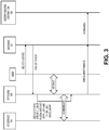
- Figure 3 illustrates a series of transactions to enroll the user with the authentication devices.
- enrollment is a prerequisite for using the enhanced security provided by the embodiments of the invention described herein.
- Enrollment involves taking a biometric reading of the user (e.g., a fingerprint, voice sample, etc) so that the same authentication device can be used to authenticate the user during a subsequent transaction.
- the enrollment operation may be done solely on the client, without interaction with the server 130.
- the user interface(s) provided for enrollment may be displayed in the browser extension or may be displayed in a separate application or mobile device app.
- the enrollment operation may be initiated as soon as devices are detected.
- the user may choose to use one or a group of discovered devices for enhanced security.
- the user may select a device from the displayed device list in the browser, application or mobile device app.
- the secure transaction plugin 105 displays a device-specific enrollment graphical user interface (GUI).
- GUI device-specific enrollment graphical user interface
- the secure transaction plugin 105 transmits the device identifier and an enrollment request to secure transaction service 101 and waits for completion. If the user is already enrolled with an authentication device on the client, the user may only need to verify their identity (i.e., they will not be required to enroll again).
- the secure transaction service 101 starts the enrollment process by activating the physical authentication device (e.g., via the device interface 102). The user then interacts with the secure transaction plugin 105 GUI and follows the specified enrollment steps (e.g., swiping a finger, speaking into a microphone, snapping a picture, etc). Once complete, the user will be enrolled with the authentication device. Significantly, once a user is enrolled with a device, they may use this enrollment to register or authenticate with any website or network service as described herein.
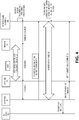
- Figure 4 illustrates a series of transactions for registration of authentication devices.
- a key is shared between the authentication device and one of the secure transaction servers 132-133.
- the key is stored within the secure storage 120 of the client 100 and the secure transaction database 120 used by the secure transaction servers 132-133.
- the key is a symmetric key generated by one of the secure transaction servers 132-133.
- asymmetric keys may be used.
- the public key may be stored by the secure transaction servers 132-133 and a second, related private key may be stored in the secure storage 120 on the client.
- the key(s) may be generated on the client 100 (e.g., by the authentication device or the authentication device interface rather than the secure transaction servers 132-133).
- a secure key provisioning protocol such as the Dynamic Symmetric Key Provisioning Protocol (DSKPP) may be used to share the key with the client over a secure communication channel (see, e.g., Request for Comments (RFC) 6063).
- DSKPP Dynamic Symmetric Key Provisioning Protocol
- RRC Request for Comments
- the underlying principles of the invention are not limited to any particular key provisioning protocol.
- the server 130 generates a randomly generated challenge (e.g., a cryptographic nonce) that must be presented by the client during device registration.
- the random challenge may be valid for a limited period of time.
- the secure transaction plugin detects the random challenge and forwards it to the secure transaction service 101.
- the secure transaction service initiates an out-of-band session with the server 130 (e.g., an out-of-band transaction) and communicates with the server 130 using the key provisioning protocol.
- the server 130 locates the user with the user name, validates the random challenge, validates the device's authentication code if one was sent, and creates a new entry in the secure transaction database 120 for the user.
- the authentication device and the server 130 share the same key if a symmetric key was used or different keys if asymmetric keys were used.
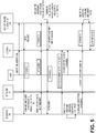
- Figure 5 illustrates a series of transactions for user authentication with the registered authentication devices. Once device registration is complete the server 130 will accept a token generated by the local authentication device as a valid authentication token.
- the user enters the uniform resource locator (URL) of the server 130 in the browser 104.
- the user may enter a network address for a network service or the application or app may automatically attempt to connect to the network service at the network address.
- the website embeds a query for registered devices in the HTML page. This may be done in many ways other than embedding the query in an HTML page, such as through Javascript or using HTTP headers.
- the secure transaction plugin 105 receives the URL and sends it to secure transaction service 101, which searches the looks into the secure storage 120 (which, as discussed, includes a database of authentication device and user information) and determines whether there is a user enrolled within this URL. If so, the secure transaction service 101 sends a list of provisioned devices associated with this URL to the secure transaction plugin 105.
- the secure transaction plugin then calls the registered JavaScript API and passes this information to the server 130 (e.g., the website).
- the server 130 chooses the appropriate device from the sent device list, generates a random challenge and sends the device information, and argument back to the client.
- the website displays the corresponding user interface and asks for authentication from the user.
- the user then provides the requested authentication measure (e.g., swiping a finger across the fingerprint reader, speaking for voice recognition, etc).
- the secure transaction service 101 identifies the user (this step can be skipped for devices which don't support storing users), obtains the username from the database, generates an authentication token using the key and sends this information to the website via the secure transaction plugin.
- the server 130 identifies the user from the secure transaction database 120 and verifies the token by generating the same token on the server 130 (e.g., using its copy of the key). Once verified, the authentication process is complete.
- Figure 6 illustrates a secure transaction following authentication for a browser-based implementation.
- the secure transaction is designed to provide stronger security for certain types of transactions (e.g., financial transactions).
- the user confirms each transaction prior to committing the transaction.
- the user confirms exactly what he/she wants to commit and commits exactly what he/she sees displayed in the GUI.
- this embodiment ensures that the transaction text cannot be modified by a "man in the middle" to commit a transaction which the user did not confirm.
- the secure transaction plugin 105 displays a window 601 in the browser context to show the transaction details.
- the secure transaction server 101 periodically (e.g., with a random interval) verifies that the text that is shown in the window is not being tampered by anyone.
- a user chooses items for purchase from a merchant site and selects "check out.”
- the merchant site sends the transaction to a service provide which has a secure transaction server 132-133 implementing one or more of the embodiments of the invention described herein (e.g., PayPal).
- the merchant site authenticates the user and completes the transaction.
- the secure transaction server 132-133 receives the transaction details (TD) and puts a "Secure Transaction" request in an HTML page and sends to client 100.
- the Secure Transaction request includes the transaction details and a random challenge (e.g., a random nonce).
- the secure transaction plugin 105 detects the request for transaction confirmation message and forwards all data to the secure transaction service 101. In an embodiment which does not use a browser or plugin, the information may be sent directly from the secure transaction servers to the secure transaction service on the client 100.
- the secure transaction plugin 105 displays a window 601 with transaction details to the user (in a browser context) and asks the user to provide authentication to confirm the transaction.
- the secure transaction service 101 or application 154 may display the window 601.
- the secure transaction service 101 starts a timer and verifies the content of the window 601 being displayed to the user. The period of verification may be randomly chosen.
- the secure transaction service 101 ensures that user sees the valid transaction details in the window 601. If it detects that the content has been tampered with it prevents the confirmation token from being generated.
- the device After the user provides valid authentication (e.g., swipes a finger on the fingerprint sensor), the device identifies the user and generates a token (cryptographic signature) with the transaction details and the random challenge (i.e., the token is calculated over the transaction details and the nonce).
- a token cryptoographic signature
- the secure transaction service 101 sends the generated token and username to the secure transaction plugin 105 which forwards the token to the secure transaction server 132-133.
- the secure transaction server 132-133 identifies the user with the username and verifies the token. If verification succeeds, a confirmation message is sent to the client and the transaction is processed.
- one embodiment of the invention implements a query policy in which a secure transaction server transmits a server policy to the client indicating the authentication capabilities accepted by the server.
- the client analyzes the server policy to identify a subset of authentication capabilities which it supports and/or which the user has indicated a desire to use.
- the client registers and/or authenticates the user using the subset of authentication tokens matching the provided policy. Consequently, there is a lower impact to the client's privacy because the client is not required to transmit exhaustive information about its authentication capabilities (e.g., all of its authentication devices) or other information which might be used to uniquely identify the client.
- the client may include numerous authentication capabilities such as a fingerprint sensor, voice recognition capabilities, facial recognition capabilities, eye/optical recognition capabilities, a trusted platform module (TPM), and smartcard, to name a few.
- TPM trusted platform module
- the secure transaction server may transmit a server policy to the client indicating that it supports, for example, fingerprint, optical, or smartcard authentication. The client may then compare the server policy against its own authentication capabilities and choose one or more of the available authentication options.
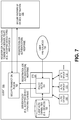
- FIG. 7 illustrates one embodiment of a client-server architecture for implementing these techniques.
- the secure transaction service 101 implemented on the client 100 includes a policy filter 701 for analyzing the policy provided by the server 130 and identifying a subset of authentication capabilities to be used for registration and/or authentication.
- the policy filter 701 is implemented as a software module executed within the context of the secure transaction service 101. It should be noted, however, that the policy filter 701 may be implemented in any manner while still complying with the underlying principles of the invention and may include software, hardware, firmware, or any combination thereof.
- the particular implementation shown in Figure 7 includes a secure transaction plugin 105 for establishing communication with the secure enterprise or Web destination 130 (sometimes referred to simply as "server 130") using techniques previously discussed.
- the secure transaction plugin may identify a specific HTML tag inserted into the HTML code by a web server 131.
- the server policy is provided to the secure transaction plugin 105 which forwards it to the secure transaction service 101 implementing the policy filter 701.
- the policy filter 701 may determine the client authentication capabilities by reading the capabilities from the client's secure storage area 720.
- the secure storage 720 may comprise a repository of all of the client's authentication capabilities (e.g., identification codes for all of the authentication devices). If the user has already enrolled the user with its authentication devices, the user's enrollment data is stored within the secure storage 720. If the client has already registered an authentication device with a server 130, then the secure storage may also store an encrypted secret key associated with each authentication device.
- the policy filter 701 may then identify a subset of authentication capabilities to be used. Depending on the configuration, the policy filter 701 may identify a complete list of authentication capabilities supported by both the client and the server or may identify a subset of the complete list. For example, if the server supports authentication capabilities A, B, C, D, and E and the client has authentication capabilities A, B, C, F, and G, then the policy filter 701 may identify the entire subset of common authentication capabilities to the server: A, B, and C. Alternatively, if a higher level of privacy is desired, as indicated by user preferences 730 in Figure 7 , then a more limited subset of authentication capabilities may be identified to the server.
- the user may indicate that only a single common authentication capability should be identified to the server (e.g., one of A, B or C).
- the user may establish a prioritization scheme for all of the authentication capabilities of the client 100 and the policy filter may select the highest priority authentication capability (or a prioritized set of N authentication capabilities) common to both the server and the client.
- the secure transaction service 130 performs that operation on the filtered subset of authentication devices (110-112) and sends the operation response back to server 130 via the secure transaction plugin 105 as shown in Figure 7 .
- the information may be passed directly from the secure transaction service 101 to the server 130.
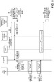
- Figure 8 illustrates a transaction diagram showing additional details for an exemplary series of registration with query policy transaction.
- the user has not previously registered devices with the server 130. Consequently, at 801 the user may enter a user name and password as an initial, one-time authentication step, which is forwarded at 802 to the server 130 via the client browser 104. It should be noted, however, that a user name and password are not required for complying with the underlying principles of the invention.
- the server 130 transmits its server policy to the client at 804.
- the server policy may include an indication of the authentication capabilities supported by the server 130.
- the server policy is passed to the secure transaction service 101 via transaction 806.
- the secure transaction service 101 compares the server policy with the capabilities of the client (and potentially other information such as device priority scheme and/or user preferences as described above) to arrive at a filtered list of authentication capabilities.
- the filtered list of devices (102) then generate keys (808 and 809) and then provide public parts of these keys to secure transaction service 101 which in its turn sends these as registration response back to server 130.
- the server attests the authentication devices and stores public keys in secure transaction database.
- the Token Attestation employed here is the process of validating authentication device identity during registration. It allows server to cryptographically make sure that the device reported by Client is really who it claimed to be.
- the user may be provided with an opportunity to review the list and/or select specific authentication capabilities to be used with this particular server 130.
- the filtered list may indicate the option to use authentication with a fingerprint scan, facial recognition, and/or voice recognition. The user may then choose to use one or more of these options when authenticating with the server 130.
- a browser plugin architecture is not required for complying with the underlying principles of the invention.
- the transaction diagram shown in Figure 8 may be simplified such that the browser 104 is removed, and the secure transaction service 101 communicates directly with the server 130.
- One embodiment of the invention is capable of enrolling, registering, and authenticating multiple devices at the same time, thereby improving efficiency and the user experience. For example, instead of requesting registration and authentication for a single device at a time, a list of devices may be sent to the client. Symmetric or asymmetric keys may then be registered into multiple devices in one operation, or series of sequential operations executed locally on the client. For authentication, several tokens/devices may be selected concurrently for a given transaction.
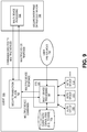
- Figure 9 illustrates one embodiment of a client-server architecture for implementing these techniques.
- the secure transaction service 101 implemented on the client 100 includes multi-device processing logic 901 for performing specified operations such as enrollment and registration of multiple devices at a time without the need for continual back-and-forth communication with the server 130 as each device is enrolled/registered.
- the server 130 includes multi-device processing logic for issuing commands directed to multiple authentication devices.
- the multi-device processing logic 901 is implemented as a software module executed within the context of the secure transaction service 101. It should be noted, however, that the multi-device processing logic 901 may be implemented in any manner while still complying with the underlying principles of the invention and may include software, hardware, or firmware components, or any combination thereof.
- the particular implementation shown in Figure 9 includes secure transaction plugin 105 for establishing communication with the server 130 (which, as discussed, may include a Website server 131 and secure transaction servers 132-133).
- the server 130 communicates with the secure transaction service 101 via the secure transaction plugin 105.
- a browser-based plugin architecture is not required for complying with the underlying principles of the invention.
- the multi-device processing logic 902 on the server 130 may communicate commands to be executed by the multi-device processing logic 901 on the client 100 which performs the operations on multiple authentication devices 110-112.
- the multi-device processing logic 902 may generate N keys to be registered with each of N authentication devices and then transmit securely to the multi-device processing logic 901 along with a command to register the N devices.
- the multi-device processing logic 901 may then perform the registration concurrently or in a series of sequential operations for all N devices (e.g., for authentication devices 110-112) without further interaction with the server. A single response may then be sent to the server 130 to indicate the completed registration of all N devices.
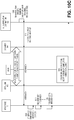
- Figures 10A-C A series of exemplary multiple-device transactions are illustrated in Figures 10A-C .
- Figure 10A illustrates a multiple-device enrollment process which may be performed without any interaction with the server 130 (e.g., enrolling the user with authentication devices may be performed under the control of the secure transaction service 101 on the client).
- the server 130 may transmit a request to the client (now shown) to enroll the user with the N devices.
- Figures 10B-C illustrate two different embodiments for registering multiple devices with the server 130.
- the user indicates a desire to enroll with N authentication devices on the client (representing all or a subset of the available authentication devices).
- the secure transaction plugin is called at 1002 and, at 1003, a device-specific graphical user interface (GUI) is generated to walk the user through the process or enrolling with authentication device # 1.
- GUI graphical user interface
- the user interacts with the secure transaction plugin as indicated (e.g., by positioning a finger over a fingerprint sensor, speaking into a microphone, snapping a picture with the camera, etc).
- enrollment is performed for each of the N devices until enrollment is completed for the Nth device at 1004.
- a different, device-specific script and/or user interface may be presented to the user to enroll the user with each individual authentication device.
- the user enrollment data may be stored within the secure storage 720 on the client 100 and made accessible only through the secure transaction service 101. Once enrollment for all N devices is complete, a notification may be sent to the server 130 via transactions 1004-1005.
- the transaction diagram shown in Figure 10B may be used to register the N devices with the server 130.
- the server 130 generates a user-specific random challenge which, as previously described, may only be valid for a limited window of time and may comprise a randomly-generated code such as a cryptographic nonce.
- the random challenge is transmitted along with a command to register N authentication devices with the server 130.
- the secure transaction service 101 creates a secure connection with the server 130 and transmits identification data for the N devices, along with the random challenge.
- the secure connection is an HTTPS connection.
- the underlying principles of the invention are not limited to any particular secure connection type.
- the server 130 attests the N devices, generates a key for each of the N devices, and sends the N keys back to the secure transaction service over the secure connection.
- the Dynamic Symmetric Key Provisioning Protocol (DSKPP) is used to exchange keys with the client over the secure connection.
- DSKPP Dynamic Symmetric Key Provisioning Protocol
- the keys may be generated in each Authentication Device and then transmitted to server 130.
- the multi-device processing logic of the secure transaction service registers each of the N keys into each of the N devices. As previously described, each key may be stored and associated with its respective device within the secure storage 720 on the client. Once registration is complete for each authentication device, a notification is sent to the server over the secure connection at 1016.
- the keys registered into each authentication device are symmetric keys.
- an identical copy of each key is stored in the secure storage 720 on the client and the secure transaction database 120 on the server 130.
- asymmetric key pairs may be generated, with one of the keys being maintained as a public key in the secure transaction database 120 on the server and the private key being stored in the secure storage 720 of the client. It should be noted, however, that the underlying principles of the invention are not limited to any particular type of encryption keys.
- FIG. 10C An alternate implementation is illustrated in Figure 10C in which keys are generated on the client rather than the server 130.
- the multi-device processing logic of the secure transaction service 101 after receiving the request to register devices with the random challenge at 1011, the multi-device processing logic of the secure transaction service 101 generates N keys for each of the N devices at 1120. Once generated, the keys are registered with each of the N devices at 1013-1014 and the registration stored within the secure storage 720 as previously described. Once all keys have been registered, the secure transaction service 101 provides a notification to the server at 1015 along with the random challenge (to verify the identity of the client). The server 130 may then store the registration in the secure transaction database 120 as described above.
- the random challenge comprises a randomly generated code such as a cryptographic nonce.
- the random challenge is no longer valid and the client will receive an error in response to a subsequent authentication attempt (e.g., the user will swipe a finger on the fingerprint reader and be denied).
- the client automatically detects that the challenge has expired and transparently requests a new challenge from the server (i.e., without user intervention).
- the server then generates a new random challenge and transmits it to the client which may then use it to establish secure communication with the server.
- the end user experience is improved because the user does not receive an error or denial of an authentication request.
- Figure 11A illustrates one such embodiment which is used within the context of a registration process
- Figure 11B illustrates an embodiment which is used within the context of an authentication process. It should be noted, however, that the underlying principles of the invention may be employed in other contexts than those shown in Figures 11A-B . For example, the techniques described herein may be used with any process in which a time-sensitive code is communicated from a server to a client.
- the server 130 generates a random challenge and an indication of a timeout period.
- the timeout period comprises a period of time for which the random challenge is considered valid. After the timeout period has elapsed, the random challenge is no longer considered valid by the server 130.
- the timeout period is specified simply as a point in time at which the random challenge will no longer be valid. Once this point in time is reached, the random challenge is invalid.
- the timeout period is specified by using a current timestamp (i.e., the time at which the random challenge is generated by the server 130) and a duration.
- the secure transaction service 101 may then calculate the timeout time by adding the duration value to the timestamp to calculate the point in time when the random challenge becomes invalid. It should be noted, however, that the underlying principles of the invention are not limited to any specific technique for calculating the timeout period.
- the random challenge and the timeout indication are transmitted to the secure transaction service 101 (via the browser 104 and secure transaction plugin 105 in the illustrated example).
- the secure transaction service 101 detects that the random challenge has timed out and is no longer valid based on the timeout indication sent from the server 130.
- the user may have turned off his/her client machine or closed the lid on his/her notebook computer prior to completing the series of transactions. If the transaction is one which requires user interaction, the user may have simply walked away or ignored a message displayed within the GUI.
- the secure transaction service 101 transmits a request for a new random challenge to the server 130 (via the secure transaction plugin 105 and browser 104 in the illustrated example).
- the server 130 generates a new random challenge an a new indication of the timeout period.
- the timeout period is the same as in operation 1101 or may be modified.
- the server 130 may increase the duration of the timeout period to reduce data traffic with the client or decrease the duration to increase the level of security provided by the random challenge.
- the new random challenge and timeout indication is transmitted to the secure transaction service 101.
- the secure transaction service opens a secure connection directly to the server at 1107 in order to perform device registration and key exchange as discussed above with respect to Figure 4 , Figure 10B , or Figure 10C .
- the server 130 identifies the user (e.g., with a user name or other ID), attests authentication device, and generates a key for the device.
- the key may be a symmetric key or an asymmetric key.
- the keys are transmitted to the secure transaction service 101 via the secure connection and, at 1110, the secure transaction service 101 registers the key into the authentication device.
- a notification that registration is complete is transmitted to the server 130.
- the key used for device registration is generated at the server 130 as in the embodiment shown in Figure 10B .
- the underlying principles of the invention may also be used in an embodiment in which the key(s) are generated by the secure transaction service 101 on the client 100, such as that described above with respect to Figure 10C .
- Figure 11B illustrates one embodiment of the invention implemented within the context of an authentication process.
- the user enters a particular website URL into the browser 104 and is directed to the web server 131 within the enterprise/web destination servers 130 which includes the secure transaction servers 132-133.
- a query is sent back to the secure transaction service (via the browser and plugin) to determine which device(s) are registered with the website's URL.
- the secure transaction service 101 queries the secure storage 720 on the client 100 to identify a list of devices which are sent back to the server 130 at 1153.
- the server 1154 chooses a device to use for authentication, generates a random challenge and a timeout indication and, at 1155, sends this information back to the secure transaction service 101.
- the secure transaction service 1156 automatically detects that the random challenge is no longer valid upon reaching the end of the timeout period. As mentioned above, various different techniques may be employed for indicating and detecting the end of the timeout period (see Figure 11A and associated text).
- the secure transaction service 101 transparently (i.e., without user intervention) notifies the server 130 and requests a new random challenge.
- the server 130 generates a new random challenge and a new indication of the timeout period.
- the new timeout period may be the same as previously sent to the client or may be modified. In either case, at 1159, the new random challenge and timeout indication are sent to the secure transaction service 101.
- an authentication user interface is displayed (e.g., directing the user to swipe a finger on a fingerprint sensor) and, at 1161, the user provides authentication (e.g., swipes a finger on the fingerprint scanner).
- the secure transaction service verifies the identity of the user (e.g., comparing the authentication data collected from the user with that stored in the secure storage 720) and uses the key associated with the authentication device to encrypt the random challenge.
- the user name (or other ID code) and the encrypted random challenge are sent to the server 130.
- the server 130 identifies the user within the secure transaction database 120 using the user name (or other ID code), and decrypts/verifies the random challenge using the key stored in the secure transaction database 120 to complete the authentication process.
- multiple classes of privacy protection may be predefined, selected and/or modified by the end user.
- the privacy classes may be defined based on the probability with which a client can be identified using the divulged information. At privacy classes having relatively higher privacy levels, relatively less information about the client device is divulged to perform the authentication techniques described herein.
- the user may choose to disclose the least amount of information possible when communicating with different servers (i.e., may choose transactions having the lowest allowable privacy impact for each website or network service).
- Figure 12 illustrates a high level architecture for implementing privacy classes.
- the secure transaction service 101 of this embodiment includes privacy management logic 1201 for analyzing queries received from the server 130 for client information such as information related to authentication devices, implementing a privacy policy in response to such queries, and generating a response containing client information collected based on the particular privacy class in use.
- the privacy management module 1201 is implemented as a software module executed within the context of the secure transaction service 101. It should be noted, however, that the privacy management module 1201 may be implemented in any manner while still complying with the underlying principles of the invention and may include software, hardware, firmware, or any combination thereof.
- the privacy classes utilized by the privacy management logic 1201 may be pre-specified and stored on the client 100 (e.g., within stored within secure storage 720).
- three privacy classes are defined: high privacy impact, medium privacy impact, and low privacy impact.
- Each privacy class may be defined based on a probability with which the divulged information could be used to uniquely identify a user/client. For example, the information divulged for a low privacy impact transaction may result in a 10% probability of the user or machine being uniquely identified over internet; a medium privacy impact transaction may result in a 50% probability of the user or machine being uniquely identified; and a high privacy impact transaction may result in a 100% probability of the user or machine being uniquely identified.
- Various other privacy class levels may be defined while still complying with the underlying principles of the invention.
- each relying party may specify a required privacy class or other privacy threshold. For example, websites and services requiring a heightened level of security may only allow communication in accordance with the high privacy impact class whereas other websites/services may permit interactions using the medium privacy impact or low privacy impact class.
- the query for client information sent from the server 130 includes an attribute specifying which privacy classes of information should be retrieved (i.e. low, medium, high).
- the privacy management logic 1201 will store information for the highest approved privacy class for each relying party.
- the privacy management logic may store the new association between the relying party (e.g., identified via a URL) and the new privacy class.
- While the user preferences 1230 are applied directly to the privacy management logic in Figure 12 for simplicity, it should be noted that the user may specify preferences via a browser-based graphical user interface (not shown). In such a case, the user would enter privacy setting via a browser window. The secure transaction plugin 105 would then store the new settings to the privacy management logic 1201, or to a configuration data file accessible by the privacy management logic 1201. In short, the underlying principles of the invention are not limited to any particular mechanism for configuring the privacy management logic.
- client data may be specified at the various privacy class levels including, for example, a machine model identifier, client software information, client capabilities, and various levels of information related to each authentication device configured on the client device (e.g., device ID codes, vendor ID codes, device class ID, etc). Different combinations of this information may be gathered to determine the percentages specified above defining the different privacy classes.
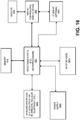
- Figure 13 illustrates a series of transactions for providing information to a requesting party using defined privacy classes.
- the server 130 generates a notification containing a query for client device information.
- the query is sent to the client and ultimately received by the secure transaction service 101.
- the privacy management logic of the secure transaction service determines a privacy class for the response and collects the necessary information.
- N different privacy class levels may be defined and the secure transaction service 101 may choose the one which complies with the requirements of the requesting party while at the same time divulges as little information as possible regarding the client.
- the collected information is sent to the server 130 and at 1305, the server uses the information for one or more subsequent transactions with the client.
- One embodiment of the invention employs transaction signing on the secure transaction server so that no transaction state needs to be maintained on the server to maintain sessions with clients.
- transaction details such as transaction text may be sent to the client signed by server.
- the server may then verify that the signed transaction responses received by the client are valid by verifying the signature.
- the server does not need to persistently store the transaction content, which would consume a significant amount of storage space for a large number of clients and would open possibility for denial of service type attacks on server.
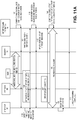
- Figure 14 shows a website or other network service (1401) initiating a transaction with a client 100.
- the user may have selected items for purchase on the website and may be ready to check out and pay.
- the website or service 1401 hands off the transaction to a secure transaction server 1402 which includes signature processing logic 1403 for generating and verifying signatures (as described herein) and authentication logic for performing client authentication 1404 (e.g., using the authentication techniques previously described).
- the authentication request sent from the secure transaction server 1402 to the client 100 includes the random challenge such as a cryptographic nonce (as described above), the transaction details (e.g., the specific text presented to complete the transaction), and a signature generated by the signature processing logic 1403 over the random challenge and the transaction details using a private key (known only by the secure transaction server).
- the random challenge such as a cryptographic nonce (as described above)
- the transaction details e.g., the specific text presented to complete the transaction
- a signature generated by the signature processing logic 1403 over the random challenge and the transaction details using a private key (known only by the secure transaction server).
- the user may receive an indication that authentication is required to complete the transaction.
- the user may, for example, swipe a finger across a fingerprint scanner, snap a picture, speak into a microphone, or perform any other type of authentication permitted for the given transaction.
- the client transmits the following back to the server: (1) the random challenge and transaction text (both previously provided to the client by the server), (2) authentication data proving that the user successfully completed authentication, and (3) the signature.
- the authentication module 1404 on the secure transaction server 1402 may then confirm that the user has correctly authenticated and the signature processing logic 1403 re-generates the signature over the random challenge and the transaction text using the private key. If the signature matches the one sent by the client, then the server can verify that the transaction text is the same as it was when initially received from the website or service 1401. Storage and processing resources are conserved because the secure transaction server 1402 is not required to persistently store the transaction text (or other transaction data) within the secure transaction database 120.
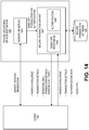
- Figure 15 is a block diagram illustrating an exemplary clients and servers which may be used in some embodiments of the invention. It should be understood that while Figure 15 illustrates various components of a computer system, it is not intended to represent any particular architecture or manner of interconnecting the components as such details are not germane to the present invention. It will be appreciated that other computer systems that have fewer components or more components may also be used with the present invention.
- the computer system 1500 which is a form of a data processing system, includes the bus(es) 1550 which is coupled with the processing system 1520, power supply 1525, memory 1530, and the nonvolatile memory 1540 (e.g., a hard drive, flash memory, Phase-Change Memory (PCM), etc.).
- the bus(es) 1550 may be connected to each other through various bridges, controllers, and/or adapters as is well known in the art.
- the processing system 1520 may retrieve instruction(s) from the memory 1530 and/or the nonvolatile memory 1540, and execute the instructions to perform operations as described above.
- the bus 1550 interconnects the above components together and also interconnects those components to the optional dock 1560, the display controller & display device 1570, Input/Output devices 1580 (e.g., NIC (Network Interface Card), a cursor control (e.g., mouse, touchscreen, touchpad, etc.), a keyboard, etc.), and the optional wireless transceiver(s) 1590 (e.g., Bluetooth, WiFi, Infrared, etc.).
- NIC Network Interface Card
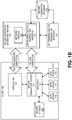
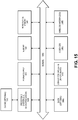
- Figure 16 is a block diagram illustrating an exemplary data processing system which may be used in some embodiments of the invention.
- the data processing system 1600 may be a handheld computer, a personal digital assistant (PDA), a mobile telephone, a portable gaming system, a portable media player, a tablet or a handheld computing device which may include a mobile telephone, a media player, and/or a gaming system.
- the data processing system 1600 may be a network computer or an embedded processing device within another device.
- the exemplary architecture of the data processing system 1600 may be used for the mobile devices described above.
- the data processing system 1600 includes the processing system 1620, which may include one or more microprocessors and/or a system on an integrated circuit.
- the processing system 1620 is coupled with a memory 1610, a power supply 1625 (which includes one or more batteries) an audio input/output 1640, a display controller and display device 1660, optional input/output 1650, input device(s) 1670, and wireless transceiver(s) 1630.
- additional components not shown in Figure 16 , may also be a part of the data processing system 1600 in certain embodiments of the invention, and in certain embodiments of the invention fewer components than shown in Figure 16 may be used.
- one or more buses, not shown in Figure 16 may be used to interconnect the various components as is well known in the art.
- the memory 1610 may store data and/or programs for execution by the data processing system 1600.
- the audio input/output 1640 may include a microphone and/or a speaker to, for example, play music and/or provide telephony functionality through the speaker and microphone.
- the display controller and display device 1660 may include a graphical user interface (GUI).
- the wireless (e.g., RF) transceivers 1630 e.g., a WiFi transceiver, an infrared transceiver, a Bluetooth transceiver, a wireless cellular telephony transceiver, etc.
- the one or more input devices 1670 allow a user to provide input to the system. These input devices may be a keypad, keyboard, touch panel, multi touch panel, etc.
- the optional other input/output 1650 may be a connector for a dock.
- Embodiments of the invention may include various steps as set forth above.
- the steps may be embodied in machine-executable instructions which cause a general-purpose or special-purpose processor to perform certain steps.
- these steps may be performed by specific hardware components that contain hardwired logic for performing the steps, or by any combination of programmed computer components and custom hardware components.
- Elements of the present invention may also be provided as a machine-readable medium for storing the machine-executable program code.
- the machine-readable medium may include, but is not limited to, floppy diskettes, optical disks, CD-ROMs, and magneto-optical disks, ROMs, RAMs, EPROMs, EEPROMs, magnetic or optical cards, or other type of media/machine-readable medium suitable for storing electronic program code.
Description
- This invention relates generally to the field of data processing systems. More particularly, the invention relates to a query system and method for determine authentication capabilities.
- Existing systems have been designed for providing secure user authentication over a network using biometric sensors. In particular, an Online Secure Transaction Plugin (OSTP) protocol developed by the Fast Identify Online (FIDO) alliance enables strong authentication (e.g., protection against identity theft and phishing), secure transactions (e.g., protection against "malware in the browser" and "man in the middle" attacks for transactions), and enrollment/management of client authentication tokens (e.g., fingerprint readers, facial recognition devices, smartcards, trusted platform modules, etc). Details of the existing OSTP protocol can be found, for example, in
U.S. Patent Application No. 201 1 /0082801 ("'801 Application"), and the document entitled OSTP Framework (March 23, 2011), both of which describe a framework for user registration and authentication on a network. - Prior art document
US 2012/278873 A1 discloses techniques for resource operation based on usage, sharing, and recommendations with modular authentication are provided. A resource space is associated with a principal. The resource space comprises resources local to a device of the principal and remote from the device. The resources presented in a merged view within a local file system and operating system of the device. In an embodiment, the device negotiates authentication with an intermediary for access to a legacy service where authentication is performed by the intermediary on behalf of the device, and the intermediary establishes an authentication session between the principal and the legacy service. - Prior art document
US 2006/026671 A1 discloses a method for determining the authentication capabilities of a supplicant before initiating an authentication conversation with a client. The method provides for sending, to a supplicant that is requesting access to a computer network subject to authentication of a user of the supplicant, a list of first authentication methods that are supported by an authentication server; receiving, from the supplicant, a counter-list of second authentication methods that are supported by the supplicant; determining how many second authentication methods in the counter-list match the first authentication methods; and performing an authentication policy action based on how many of the second authentication methods match the first authentication methods. - A better understanding of the present invention can be obtained from the following detailed description in conjunction with the following drawings, in which:
-
FIGS. 1A-B illustrate two different embodiments of a secure authentication system architecture. -
FIG. 2 is a transaction diagram showing how authentication devices on a client device may be discovered. -
FIG. 3 is a transaction diagram showing how a user may enroll with authentication devices. -
FIG. 4 is a transaction diagram showing how keys may be registered into authentication devices. -
FIG. 5 is a transaction diagram showing how user authentication may be implemented within an authentication framework. -
FIG. 6 is a transaction diagram showing how details of a transaction may be verified. -
FIG. 7 illustrates a query policy filter implemented in accordance with one embodiment of the invention. -
FIG. 8 is a transaction diagram showing how a registration operation with query policy is implemented in one embodiment of the invention. -
FIG. 9 illustrates one embodiment of an architecture for implementing multiple authentication device processing. -
FIG. 10A-C illustrate three embodiments of the invention for multiple authentication device processing. -
FIGS. 11A-B illustrate a transaction diagram for detecting and responding to a random challenge timeout. -
FIG. 12 illustrates an architecture for implementing privacy classes in accordance with one embodiment of the invention. -
FIG. 13 is a transaction diagram for implementing privacy classes in accordance with one embodiment of the invention. -
FIG. 14 illustrates one embodiment of an architecture for using signatures to authenticate and a transaction. -
FIGS. 15-16 illustrate exemplary embodiments of a computer system for executing embodiments of the invention. - Described below are embodiments of an apparatus, method, and machine-readable medium for intelligently implementing an authentication framework in a client-server environment. Throughout the description, for the purposes of explanation, numerous specific details are set forth in order to provide a thorough understanding of the present invention. It will be apparent, however, to one skilled in the art that the present invention may be practiced without some of these specific details. In other instances, well-known structures and devices are not shown or are shown in a block diagram form to avoid obscuring the underlying principles of the present invention. In the following, references to embodiments that are not covered by the claims are to be read as background examples for understanding the invention.
- The embodiments of the invention discussed below involve client devices with authentication capabilities such as biometric devices. These devices are sometimes referred to herein as "tokens." Various different biometric devices may be used including, but not limited to, fingerprint sensors, voice recognition hardware/software (e.g., a microphone and associated software for recognizing a user's voice), facial recognition hardware/software (e.g., a camera and associated software for recognizing a user's face), and optical recognition capabilities (e.g., an optical scanner and associated software for scanning the retina of a user). The authentication capabilities may also include non-biometric devices such as a trusted platform modules (TPMs) and smartcards.
- The embodiments of the invention described below provide various improvements over existing authentication techniques. For example, in contrast to current techniques which require a client to communicate an exhaustive list of all of its authentication capabilities (e.g., all of its authentication tokens/devices) over a network, one embodiment of the invention implements a query policy in which a secure transaction server initially transmits a server policy to the client indicating the authentication capabilities accepted by the server. The client then analyzes the server policy to identify a subset of authentication capabilities, thereby reducing the privacy impact to the client.
- In another embodiment, multiple configurable levels of privacy protection are employed. Privacy classes are predefined and may be selected and/or modified by the end user. In one embodiment of the invention, the privacy classes are defined based on the probability with which a client can be identified using the information requested. At relatively higher privacy levels (having a relatively lower privacy impact), relatively less information about the client device is divulged to perform the authentication techniques described herein.
- Another embodiment of the invention provides for the provisioning or authentication of multiple devices at the same time, thereby improving efficiency. For example, instead of requesting registration or authentication for a single authentication device at a time, a list of authentication devices may be sent from the server. Symmetric and/or asymmetric keys are then provisioned into multiple tokens/devices in one operation, or series of sequential operations executed locally on the client. For authentication, several tokens/devices may be selected concurrently for a given transaction.
- Another embodiment of the invention improves the efficiency with which server challenges are processed and managed. Today, after a server sends a random challenge to the client (e.g., a cryptographic nonce), if the client does not respond within a specified timeout period, the nonce is no longer valid and the client will receive an error in response to a subsequent authentication attempt. For example, if the user suspends the client to move to a new location (e.g., closing the lid on a laptop) and then attempts authentication, the authentication attempt will be denied. In one embodiment of the invention, the client detects that the random challenge has expired and automatically and transparently requests a new challenge from the server. The server then generates a new challenge and transmits it to the client where it may be used for authentication. The end user experience is improved because the user does not receive an error or denial of an authentication request.
- Another embodiment of the invention employs transaction signing on a secure transaction server so that no transaction state needs to be maintained on the server to maintain current sessions with clients. Transaction content such as transaction text is sent to the client signed by server, when the server responds it sends back the transaction content with the signature. The server does not need to store transaction state because it can verify that the signed transaction responses received by the client are valid by verifying the signature.
- While described above as separate embodiments, all of the above techniques may be combined together in various ways within a single comprehensive authentication system. Thus, a given embodiment of the invention may be combined with one or more other embodiments described herein for improving client and user authentication in a secure network environment.
-
Figures 1A-B illustrate two embodiments of a system architecture comprising client-side and server-side components for authenticating a user. The embodiment shown inFigure 1A uses a browser plugin-based architecture for communicating with a website while the embodiment shown inFigure 1B does not require a browser. The various techniques described herein such as enrolling a user with authentication devices, registering the authentication devices with a secure server, and authenticating a user may be implemented on either of these system architectures. Thus, while the architecture shown inFigure 1A is used to demonstrate the operation of several of the embodiments described below, the same basic principles may be easily implemented on the system shown inFigure 1B (e.g., by removing thebrowser plugin 105 as the intermediary for communication between theserver 130 and thesecure transaction service 101 on the client). - Turning first to
Figure 1A , the illustrated embodiment includes aclient 100 equipped with one or more authentication devices 110-112 (sometimes referred to in the art as authentication "tokens") for enrolling and authenticating an end user. As mentioned above, the authentication devices 110-112 may include biometric device such as fingerprint sensors, voice recognition hardware/software (e.g., a microphone and associated software for recognizing a user's voice), facial recognition hardware/software (e.g., a camera and associated software for recognizing a user's face), and optical recognition capabilities (e.g., an optical scanner and associated software for scanning the retina of a user) and non-biometric devices such as a trusted platform modules (TPMs) and smartcards. - The authentication devices 110-112 are communicatively coupled to the client through an interface 102 (e.g., an application programming interface or API) exposed by a
secure transaction service 101. Thesecure transaction service 101 is a secure application for communicating with one or more secure transaction servers 132-133 over a network and for interfacing with asecure transaction plugin 105 executed within the context of aweb browser 104. As illustrated, theInterface 102 may also provide secure access to asecure storage device 120 on theclient 100 which stores information related to each of the authentication devices 110-112 such as a device identification code, user identification code, user enrollment data (e.g., scanned fingerprint or other biometric data), and keys used to perform the secure authentication techniques described herein. For example, as discussed in detail below, a unique key may be stored into each of the authentication devices and used when communicating toservers 130 over a network such as the Internet. - As discussed below, certain types of network transactions are supported by the
secure transaction plugin 105 such as HTTP or HTTPS transactions withwebsites 131 or other servers. In one embodiment, the secure transaction plugin is initiated in response to specific HTML tags inserted into the HTML code of a web page by theweb server 131 within the secure enterprise or Web destination 130 (sometimes simply referred to below as "server 130"). In response to detecting such a tag, thesecure transaction plugin 105 may forward transactions to thesecure transaction service 101 for processing. In addition, for certain types of transactions (e.g., such as secure key exchange) thesecure transaction service 101 may open a direct communication channel with the on-premises transaction server 132 (i.e., co-located with the website) or with an off-premises transaction server 133. - The secure transaction servers 132-133 are coupled to a
secure transaction database 120 for storing user data, authentication device data, keys and other secure information needed to support the secure authentication transactions described below. It should be noted, however, that the underlying principles of the invention do not require the separation of logical components within the secure enterprise orweb destination 130 shown inFigure 1A . For example, thewebsite 131 and the secure transaction servers 132-133 may be implemented within a single physical server or separate physical servers. Moreover, thewebsite 131 and transaction servers 132-133 may be implemented within an integrated software module executed on one or more servers for performing the functions described below. - As mentioned above, the underlying principles of the invention are not limited to a browser-based architecture shown in
Figure 1A .Figure 1B illustrates an alternate implementation in which a stand-alone application 154 utilizes the functionality provided by thesecure transaction service 101 to authenticate a user over a network. In one embodiment, theapplication 154 is designed to establish communication sessions with one ormore network services 151 which rely on the secure transaction servers 132-133 for performing the user/client authentication techniques described in detail below. - In either of the embodiments shown in
Figures 1A-B , the secure transaction servers 132-133 may generate the keys which are then securely transmitted to thesecure transaction service 101 and stored into the authentication devices within thesecure storage 120. Additionally, the secure transaction servers 132-133 manage thesecure transaction database 120 on the server side. - An exemplary series of transactions for performing authentication device discovery, enrollment, registration, and authentication are shown in
Figures 2-6 . Some aspects of these transactions have been employed in the OSTP protocol mentioned above (see the OSTP Framework (March 23, 2011) for additional details). An understanding of the basic operation of these transactions will provide a context in which embodiments of the invention may be implemented. - The operations described below include detection of authentication devices (
Figure 2 ); enrollment of the user with the authentication devices (Figure 3 ); registration of authentication devices (Figure 4 ); user authentication with the registered authentication devices (Figure 5 ); and implementation of secure transactions following authentication (Figure 6 ). -
Figure 2 illustrates a series of transactions for detecting authentication devices on the client machine. After device detection is successfully completed, theserver 130 possesses exhaustive information about the authentication devices attached to the client and will be able to assess which device(s) are most appropriate to use with the enhanced security infrastructure. Only theserver 130 filters the list of authentication devices. The user will be provided with this list and may choose one (or combination) of authentication devices to use for further authentication and implementation of secure transactions. - In operation, the user authenticates with username and password in browser and logs in to web site. This is the only time that the user will be required to provide a user name and password. The
server 130 determines that the user is not currently using enhanced security (e.g., by querying the secure transaction database 120) and provides a suggestion to the user to change to enhanced security. - In one embodiment, the
server 130 includes a "query for devices" tag in an HTML page which thesecure transaction plugin 105 detects. In response to detecting the tag, thesecure transaction plugin 105 reroutes the request to thesecure transaction service 101 which then prepares exhaustive information about all authentication devices attached to the system including security characteristics of the devices. In one embodiment, the information is packaged in an XML format prior to transmission using a pre-specified data schema. - The
secure transaction plugin 105 receives this information from thesecure transaction service 101 and, in one embodiment, passes the information to the web page's JavaScript via a registered callback. It then chooses how to display the information in thebrowser 104. The list, filtered by the website, may be shown to the user and the user may select one or a combination of authentication devices. -
Figure 3 illustrates a series of transactions to enroll the user with the authentication devices. In one embodiment, enrollment is a prerequisite for using the enhanced security provided by the embodiments of the invention described herein. Enrollment involves taking a biometric reading of the user (e.g., a fingerprint, voice sample, etc) so that the same authentication device can be used to authenticate the user during a subsequent transaction. The enrollment operation may be done solely on the client, without interaction with theserver 130. The user interface(s) provided for enrollment may be displayed in the browser extension or may be displayed in a separate application or mobile device app. - The enrollment operation may be initiated as soon as devices are detected. The user may choose to use one or a group of discovered devices for enhanced security. In operation, the user may select a device from the displayed device list in the browser, application or mobile device app. For the browser-based implementation illustrated in
Figure 3 , thesecure transaction plugin 105 displays a device-specific enrollment graphical user interface (GUI). Thesecure transaction plugin 105 transmits the device identifier and an enrollment request to securetransaction service 101 and waits for completion. If the user is already enrolled with an authentication device on the client, the user may only need to verify their identity (i.e., they will not be required to enroll again). If the user is not currently enrolled, then thesecure transaction service 101 starts the enrollment process by activating the physical authentication device (e.g., via the device interface 102). The user then interacts with thesecure transaction plugin 105 GUI and follows the specified enrollment steps (e.g., swiping a finger, speaking into a microphone, snapping a picture, etc). Once complete, the user will be enrolled with the authentication device. Significantly, once a user is enrolled with a device, they may use this enrollment to register or authenticate with any website or network service as described herein. -
Figure 4 illustrates a series of transactions for registration of authentication devices. During registration, a key is shared between the authentication device and one of the secure transaction servers 132-133. The key is stored within thesecure storage 120 of theclient 100 and thesecure transaction database 120 used by the secure transaction servers 132-133. In one embodiment, the key is a symmetric key generated by one of the secure transaction servers 132-133. However, in another embodiment discussed below, asymmetric keys may be used. In this embodiment, the public key may be stored by the secure transaction servers 132-133 and a second, related private key may be stored in thesecure storage 120 on the client. Moreover, in one embodiment (also discussed below), the key(s) may be generated on the client 100 (e.g., by the authentication device or the authentication device interface rather than the secure transaction servers 132-133). - A secure key provisioning protocol such as the Dynamic Symmetric Key Provisioning Protocol (DSKPP) may be used to share the key with the client over a secure communication channel (see, e.g., Request for Comments (RFC) 6063). However, the underlying principles of the invention are not limited to any particular key provisioning protocol.
- Turning to the specific details shown in
Figure 4 , once the user enrollment or user authentication is complete, theserver 130 generates a randomly generated challenge (e.g., a cryptographic nonce) that must be presented by the client during device registration. The random challenge may be valid for a limited period of time. The secure transaction plugin detects the random challenge and forwards it to thesecure transaction service 101. In response, the secure transaction service initiates an out-of-band session with the server 130 (e.g., an out-of-band transaction) and communicates with theserver 130 using the key provisioning protocol. Theserver 130 locates the user with the user name, validates the random challenge, validates the device's authentication code if one was sent, and creates a new entry in thesecure transaction database 120 for the user. It may also generate the key, write the key to thedatabase 120 and send the key back to thesecure transaction service 101 using the key provisioning protocol. Once complete, the authentication device and theserver 130 share the same key if a symmetric key was used or different keys if asymmetric keys were used. -
Figure 5 illustrates a series of transactions for user authentication with the registered authentication devices. Once device registration is complete theserver 130 will accept a token generated by the local authentication device as a valid authentication token. - Turning to the specific details shown in
Figure 5 , which shows a browser-based implementation, the user enters the uniform resource locator (URL) of theserver 130 in thebrowser 104. In an implementation which uses a stand alone application or mobile device app (rather than a browser), the user may enter a network address for a network service or the application or app may automatically attempt to connect to the network service at the network address. - For a browser-based implementation, the website embeds a query for registered devices in the HTML page. This may be done in many ways other than embedding the query in an HTML page, such as through Javascript or using HTTP headers. The
secure transaction plugin 105 receives the URL and sends it to securetransaction service 101, which searches the looks into the secure storage 120 (which, as discussed, includes a database of authentication device and user information) and determines whether there is a user enrolled within this URL. If so, thesecure transaction service 101 sends a list of provisioned devices associated with this URL to thesecure transaction plugin 105. The secure transaction plugin then calls the registered JavaScript API and passes this information to the server 130 (e.g., the website). Theserver 130 chooses the appropriate device from the sent device list, generates a random challenge and sends the device information, and argument back to the client. The website displays the corresponding user interface and asks for authentication from the user. The user then provides the requested authentication measure (e.g., swiping a finger across the fingerprint reader, speaking for voice recognition, etc). Thesecure transaction service 101 identifies the user (this step can be skipped for devices which don't support storing users), obtains the username from the database, generates an authentication token using the key and sends this information to the website via the secure transaction plugin. Theserver 130 identifies the user from thesecure transaction database 120 and verifies the token by generating the same token on the server 130 (e.g., using its copy of the key). Once verified, the authentication process is complete. -
Figure 6 illustrates a secure transaction following authentication for a browser-based implementation. The secure transaction is designed to provide stronger security for certain types of transactions (e.g., financial transactions). In the illustrated embodiment, the user confirms each transaction prior to committing the transaction. Using the illustrated techniques, the user confirms exactly what he/she wants to commit and commits exactly what he/she sees displayed in the GUI. In other words, this embodiment ensures that the transaction text cannot be modified by a "man in the middle" to commit a transaction which the user did not confirm. - In one embodiment, the
secure transaction plugin 105 displays awindow 601 in the browser context to show the transaction details. Thesecure transaction server 101 periodically (e.g., with a random interval) verifies that the text that is shown in the window is not being tampered by anyone. - The following example will help to highlight the operation of this embodiment. A user chooses items for purchase from a merchant site and selects "check out." The merchant site sends the transaction to a service provide which has a secure transaction server 132-133 implementing one or more of the embodiments of the invention described herein (e.g., PayPal). The merchant site authenticates the user and completes the transaction.
- The secure transaction server 132-133 receives the transaction details (TD) and puts a "Secure Transaction" request in an HTML page and sends to
client 100. The Secure Transaction request includes the transaction details and a random challenge (e.g., a random nonce). Thesecure transaction plugin 105 detects the request for transaction confirmation message and forwards all data to thesecure transaction service 101. In an embodiment which does not use a browser or plugin, the information may be sent directly from the secure transaction servers to the secure transaction service on theclient 100. - For a browser-based implementation, the
secure transaction plugin 105 displays awindow 601 with transaction details to the user (in a browser context) and asks the user to provide authentication to confirm the transaction. In an embodiment which does not use a browser or plugin, thesecure transaction service 101 orapplication 154 may display thewindow 601. Thesecure transaction service 101 starts a timer and verifies the content of thewindow 601 being displayed to the user. The period of verification may be randomly chosen. Thesecure transaction service 101 ensures that user sees the valid transaction details in thewindow 601. If it detects that the content has been tampered with it prevents the confirmation token from being generated. - After the user provides valid authentication (e.g., swipes a finger on the fingerprint sensor), the device identifies the user and generates a token (cryptographic signature) with the transaction details and the random challenge (i.e., the token is calculated over the transaction details and the nonce). This allows the secure transaction server 132-133 to ensure that the transaction details have not been modified between the server and the client. The
secure transaction service 101 sends the generated token and username to thesecure transaction plugin 105 which forwards the token to the secure transaction server 132-133. The secure transaction server 132-133 identifies the user with the username and verifies the token. If verification succeeds, a confirmation message is sent to the client and the transaction is processed. - As mentioned, one embodiment of the invention implements a query policy in which a secure transaction server transmits a server policy to the client indicating the authentication capabilities accepted by the server. The client then analyzes the server policy to identify a subset of authentication capabilities which it supports and/or which the user has indicated a desire to use.. The client then registers and/or authenticates the user using the subset of authentication tokens matching the provided policy. Consequently, there is a lower impact to the client's privacy because the client is not required to transmit exhaustive information about its authentication capabilities (e.g., all of its authentication devices) or other information which might be used to uniquely identify the client.
- By way of example, and not limitation, the client may include numerous authentication capabilities such as a fingerprint sensor, voice recognition capabilities, facial recognition capabilities, eye/optical recognition capabilities, a trusted platform module (TPM), and smartcard, to name a few. However, for privacy reasons, the user may not wish to divulge the details for all of its capabilities to a requesting server. Thus, using the techniques described herein, the secure transaction server may transmit a server policy to the client indicating that it supports, for example, fingerprint, optical, or smartcard authentication. The client may then compare the server policy against its own authentication capabilities and choose one or more of the available authentication options.
-
Figure 7 illustrates one embodiment of a client-server architecture for implementing these techniques. As illustrated, thesecure transaction service 101 implemented on theclient 100 includes apolicy filter 701 for analyzing the policy provided by theserver 130 and identifying a subset of authentication capabilities to be used for registration and/or authentication. In one embodiment, thepolicy filter 701 is implemented as a software module executed within the context of thesecure transaction service 101. It should be noted, however, that thepolicy filter 701 may be implemented in any manner while still complying with the underlying principles of the invention and may include software, hardware, firmware, or any combination thereof. - The particular implementation shown in
Figure 7 includes asecure transaction plugin 105 for establishing communication with the secure enterprise or Web destination 130 (sometimes referred to simply as "server 130") using techniques previously discussed. For example, the secure transaction plugin may identify a specific HTML tag inserted into the HTML code by aweb server 131. Thus, in this embodiment, the server policy is provided to thesecure transaction plugin 105 which forwards it to thesecure transaction service 101 implementing thepolicy filter 701. - The
policy filter 701 may determine the client authentication capabilities by reading the capabilities from the client'ssecure storage area 720. As previously discussed, thesecure storage 720 may comprise a repository of all of the client's authentication capabilities (e.g., identification codes for all of the authentication devices). If the user has already enrolled the user with its authentication devices, the user's enrollment data is stored within thesecure storage 720. If the client has already registered an authentication device with aserver 130, then the secure storage may also store an encrypted secret key associated with each authentication device. - Using the authentication data extracted from the
secure storage 720 and the policy provided by the server, thepolicy filter 701 may then identify a subset of authentication capabilities to be used. Depending on the configuration, thepolicy filter 701 may identify a complete list of authentication capabilities supported by both the client and the server or may identify a subset of the complete list. For example, if the server supports authentication capabilities A, B, C, D, and E and the client has authentication capabilities A, B, C, F, and G, then thepolicy filter 701 may identify the entire subset of common authentication capabilities to the server: A, B, and C. Alternatively, if a higher level of privacy is desired, as indicated by user preferences 730 inFigure 7 , then a more limited subset of authentication capabilities may be identified to the server. For example, the user may indicate that only a single common authentication capability should be identified to the server (e.g., one of A, B or C). In one embodiment, the user may establish a prioritization scheme for all of the authentication capabilities of theclient 100 and the policy filter may select the highest priority authentication capability (or a prioritized set of N authentication capabilities) common to both the server and the client. - Depending on what operation has been initiated by server 130 (Registration or Authentication), the
secure transaction service 130 performs that operation on the filtered subset of authentication devices (110-112) and sends the operation response back toserver 130 via thesecure transaction plugin 105 as shown inFigure 7 . Alternatively, in an embodiment which does not rely on aplugin 105 component of a Web browser, the information may be passed directly from thesecure transaction service 101 to theserver 130. -
Figure 8 illustrates a transaction diagram showing additional details for an exemplary series of registration with query policy transaction. In the illustrated embodiment, the user has not previously registered devices with theserver 130. Consequently, at 801 the user may enter a user name and password as an initial, one-time authentication step, which is forwarded at 802 to theserver 130 via theclient browser 104. It should be noted, however, that a user name and password are not required for complying with the underlying principles of the invention. - Because the user has not previously registered with enhanced security, determined at 803, the
server 130 transmits its server policy to the client at 804. As mentioned, the server policy may include an indication of the authentication capabilities supported by theserver 130. In the illustrated example, the server policy is passed to thesecure transaction service 101 viatransaction 806. - At
transaction 807, thesecure transaction service 101 compares the server policy with the capabilities of the client (and potentially other information such as device priority scheme and/or user preferences as described above) to arrive at a filtered list of authentication capabilities. The filtered list of devices (102) then generate keys (808 and 809) and then provide public parts of these keys to securetransaction service 101 which in its turn sends these as registration response back toserver 130. The server attests the authentication devices and stores public keys in secure transaction database. The Token Attestation employed here is the process of validating authentication device identity during registration. It allows server to cryptographically make sure that the device reported by Client is really who it claimed to be. - Alternatively, or in addition, at 807, the user may be provided with an opportunity to review the list and/or select specific authentication capabilities to be used with this
particular server 130. For example, the filtered list may indicate the option to use authentication with a fingerprint scan, facial recognition, and/or voice recognition. The user may then choose to use one or more of these options when authenticating with theserver 130. - The techniques described above for filtering a server policy at a client may be implemented at various different stages of the series of transactions described above (e.g., during device discovery, device registration, device provisioning, user authentication, etc). That is, the underlying principles of the invention are not limited to the specific set of transactions and the specific transaction ordering set forth in
Figure 8 . - Moreover, as previously mentioned, a browser plugin architecture is not required for complying with the underlying principles of the invention. For an architecture which does involve a browser or browser plug-ins (e.g., such as a stand-alone application or mobile device app), the transaction diagram shown in
Figure 8 (and the rest of the transaction diagrams disclosed herein) may be simplified such that thebrowser 104 is removed, and thesecure transaction service 101 communicates directly with theserver 130. - One embodiment of the invention is capable of enrolling, registering, and authenticating multiple devices at the same time, thereby improving efficiency and the user experience. For example, instead of requesting registration and authentication for a single device at a time, a list of devices may be sent to the client. Symmetric or asymmetric keys may then be registered into multiple devices in one operation, or series of sequential operations executed locally on the client. For authentication, several tokens/devices may be selected concurrently for a given transaction.
-
Figure 9 illustrates one embodiment of a client-server architecture for implementing these techniques. As illustrated, thesecure transaction service 101 implemented on theclient 100 includesmulti-device processing logic 901 for performing specified operations such as enrollment and registration of multiple devices at a time without the need for continual back-and-forth communication with theserver 130 as each device is enrolled/registered. Similarly, theserver 130 includes multi-device processing logic for issuing commands directed to multiple authentication devices. In one embodiment, themulti-device processing logic 901 is implemented as a software module executed within the context of thesecure transaction service 101. It should be noted, however, that themulti-device processing logic 901 may be implemented in any manner while still complying with the underlying principles of the invention and may include software, hardware, or firmware components, or any combination thereof. - As in the embodiments described above, the particular implementation shown in
Figure 9 includessecure transaction plugin 105 for establishing communication with the server 130 (which, as discussed, may include aWebsite server 131 and secure transaction servers 132-133). Thus, theserver 130 communicates with thesecure transaction service 101 via thesecure transaction plugin 105. As mentioned, however, a browser-based plugin architecture is not required for complying with the underlying principles of the invention. - The
multi-device processing logic 902 on theserver 130 may communicate commands to be executed by themulti-device processing logic 901 on theclient 100 which performs the operations on multiple authentication devices 110-112. By way of example, themulti-device processing logic 902 may generate N keys to be registered with each of N authentication devices and then transmit securely to themulti-device processing logic 901 along with a command to register the N devices. Themulti-device processing logic 901 may then perform the registration concurrently or in a series of sequential operations for all N devices (e.g., for authentication devices 110-112) without further interaction with the server. A single response may then be sent to theserver 130 to indicate the completed registration of all N devices. - A series of exemplary multiple-device transactions are illustrated in
Figures 10A-C .Figure 10A illustrates a multiple-device enrollment process which may be performed without any interaction with the server 130 (e.g., enrolling the user with authentication devices may be performed under the control of thesecure transaction service 101 on the client). In an alternate embodiment, theserver 130 may transmit a request to the client (now shown) to enroll the user with the N devices.Figures 10B-C illustrate two different embodiments for registering multiple devices with theserver 130. - Turning to the enrollment process in
Figure 10A , at 1001, the user indicates a desire to enroll with N authentication devices on the client (representing all or a subset of the available authentication devices). In response, the secure transaction plugin is called at 1002 and, at 1003, a device-specific graphical user interface (GUI) is generated to walk the user through the process or enrolling withauthentication device # 1. During the enrollment process, the user interacts with the secure transaction plugin as indicated (e.g., by positioning a finger over a fingerprint sensor, speaking into a microphone, snapping a picture with the camera, etc). In one embodiment, enrollment is performed for each of the N devices until enrollment is completed for the Nth device at 1004. A different, device-specific script and/or user interface may be presented to the user to enroll the user with each individual authentication device. As previously discussed, as the user enrolls with each device, the user enrollment data may be stored within thesecure storage 720 on theclient 100 and made accessible only through thesecure transaction service 101. Once enrollment for all N devices is complete, a notification may be sent to theserver 130 via transactions 1004-1005. - Regardless of how enrollment is performed, once completed, the transaction diagram shown in
Figure 10B may be used to register the N devices with theserver 130. At 1010 theserver 130 generates a user-specific random challenge which, as previously described, may only be valid for a limited window of time and may comprise a randomly-generated code such as a cryptographic nonce. At 1011, the random challenge is transmitted along with a command to register N authentication devices with theserver 130. At 1012, thesecure transaction service 101 creates a secure connection with theserver 130 and transmits identification data for the N devices, along with the random challenge. In one embodiment, the secure connection is an HTTPS connection. However, the underlying principles of the invention are not limited to any particular secure connection type. - At 1013, the
server 130 attests the N devices, generates a key for each of the N devices, and sends the N keys back to the secure transaction service over the secure connection. In one embodiment, the Dynamic Symmetric Key Provisioning Protocol (DSKPP) is used to exchange keys with the client over the secure connection. However, the underlying principles of the invention are not limited to any particular key provisioning techniques. Alternatively, in an embodiment which does not rely on DSKPP protocol, the keys may be generated in each Authentication Device and then transmitted toserver 130. - At 1014-1015, the multi-device processing logic of the secure transaction service registers each of the N keys into each of the N devices. As previously described, each key may be stored and associated with its respective device within the
secure storage 720 on the client. Once registration is complete for each authentication device, a notification is sent to the server over the secure connection at 1016. - In one embodiment, the keys registered into each authentication device are symmetric keys. Thus, an identical copy of each key is stored in the
secure storage 720 on the client and thesecure transaction database 120 on theserver 130. In an alternate implementation, asymmetric key pairs may be generated, with one of the keys being maintained as a public key in thesecure transaction database 120 on the server and the private key being stored in thesecure storage 720 of the client. It should be noted, however, that the underlying principles of the invention are not limited to any particular type of encryption keys. - An alternate implementation is illustrated in
Figure 10C in which keys are generated on the client rather than theserver 130. In this implementation, after receiving the request to register devices with the random challenge at 1011, the multi-device processing logic of thesecure transaction service 101 generates N keys for each of the N devices at 1120. Once generated, the keys are registered with each of the N devices at 1013-1014 and the registration stored within thesecure storage 720 as previously described. Once all keys have been registered, thesecure transaction service 101 provides a notification to the server at 1015 along with the random challenge (to verify the identity of the client). Theserver 130 may then store the registration in thesecure transaction database 120 as described above. - One embodiment of the invention improves the manned in which random challenges are generated by the server and processed. In one embodiment, the random challenge comprises a randomly generated code such as a cryptographic nonce. In current systems, after a server transmits a random challenge to the client, if the client does not respond within a specified timeout period, the random challenge is no longer valid and the client will receive an error in response to a subsequent authentication attempt (e.g., the user will swipe a finger on the fingerprint reader and be denied).
- In one embodiment of the invention, the client automatically detects that the challenge has expired and transparently requests a new challenge from the server (i.e., without user intervention). The server then generates a new random challenge and transmits it to the client which may then use it to establish secure communication with the server. The end user experience is improved because the user does not receive an error or denial of an authentication request.
-
Figure 11A illustrates one such embodiment which is used within the context of a registration process andFigure 11B illustrates an embodiment which is used within the context of an authentication process. It should be noted, however, that the underlying principles of the invention may be employed in other contexts than those shown inFigures 11A-B . For example, the techniques described herein may be used with any process in which a time-sensitive code is communicated from a server to a client. - Turning first to
Figure 11A , at 1101, theserver 130 generates a random challenge and an indication of a timeout period. In one embodiment, the timeout period comprises a period of time for which the random challenge is considered valid. After the timeout period has elapsed, the random challenge is no longer considered valid by theserver 130. In one embodiment, the timeout period is specified simply as a point in time at which the random challenge will no longer be valid. Once this point in time is reached, the random challenge is invalid. In another embodiment, the timeout period is specified by using a current timestamp (i.e., the time at which the random challenge is generated by the server 130) and a duration. Thesecure transaction service 101 may then calculate the timeout time by adding the duration value to the timestamp to calculate the point in time when the random challenge becomes invalid. It should be noted, however, that the underlying principles of the invention are not limited to any specific technique for calculating the timeout period. - Regardless of how the timeout period is specified or calculated, at 1102 the random challenge and the timeout indication are transmitted to the secure transaction service 101 (via the
browser 104 andsecure transaction plugin 105 in the illustrated example). At 1103, thesecure transaction service 101 detects that the random challenge has timed out and is no longer valid based on the timeout indication sent from theserver 130. By way of example, the user may have turned off his/her client machine or closed the lid on his/her notebook computer prior to completing the series of transactions. If the transaction is one which requires user interaction, the user may have simply walked away or ignored a message displayed within the GUI. - At 1104, upon detecting that the random challenge is no longer valid, the
secure transaction service 101 transmits a request for a new random challenge to the server 130 (via thesecure transaction plugin 105 andbrowser 104 in the illustrated example). At 1105, theserver 130 generates a new random challenge an a new indication of the timeout period. In one embodiment, the timeout period is the same as inoperation 1101 or may be modified. For example, theserver 130 may increase the duration of the timeout period to reduce data traffic with the client or decrease the duration to increase the level of security provided by the random challenge. At 1106, the new random challenge and timeout indication is transmitted to thesecure transaction service 101. - The remainder of the transactions occurs as previously described. For example, the secure transaction service opens a secure connection directly to the server at 1107 in order to perform device registration and key exchange as discussed above with respect to
Figure 4 ,Figure 10B , orFigure 10C . At 1108, theserver 130 identifies the user (e.g., with a user name or other ID), attests authentication device, and generates a key for the device. As mentioned, the key may be a symmetric key or an asymmetric key. At 1109, the keys are transmitted to thesecure transaction service 101 via the secure connection and, at 1110, thesecure transaction service 101 registers the key into the authentication device. At 1111, a notification that registration is complete is transmitted to theserver 130. - Thus, in the embodiment shown in
Figure 11A , the key used for device registration is generated at theserver 130 as in the embodiment shown inFigure 10B . However, the underlying principles of the invention may also be used in an embodiment in which the key(s) are generated by thesecure transaction service 101 on theclient 100, such as that described above with respect toFigure 10C . -
Figure 11B illustrates one embodiment of the invention implemented within the context of an authentication process. At 1151, the user enters a particular website URL into thebrowser 104 and is directed to theweb server 131 within the enterprise/web destination servers 130 which includes the secure transaction servers 132-133. At 1152, a query is sent back to the secure transaction service (via the browser and plugin) to determine which device(s) are registered with the website's URL. Thesecure transaction service 101 queries thesecure storage 720 on theclient 100 to identify a list of devices which are sent back to theserver 130 at 1153. At 1154, the server 1154 chooses a device to use for authentication, generates a random challenge and a timeout indication and, at 1155, sends this information back to thesecure transaction service 101. - At 1156, the
secure transaction service 1156 automatically detects that the random challenge is no longer valid upon reaching the end of the timeout period. As mentioned above, various different techniques may be employed for indicating and detecting the end of the timeout period (seeFigure 11A and associated text). Upon detecting the expiration of the random challenge, at 1157, thesecure transaction service 101 transparently (i.e., without user intervention) notifies theserver 130 and requests a new random challenge. In response, at 1158, theserver 130 generates a new random challenge and a new indication of the timeout period. As mentioned, the new timeout period may be the same as previously sent to the client or may be modified. In either case, at 1159, the new random challenge and timeout indication are sent to thesecure transaction service 101. - The remainder of the transaction diagram shown in
Figure 11B operates in substantially the same manner as described above (see, e.g.,Figure 5 ). For example, at 1160, an authentication user interface is displayed (e.g., directing the user to swipe a finger on a fingerprint sensor) and, at 1161, the user provides authentication (e.g., swipes a finger on the fingerprint scanner). At 1162, the secure transaction service verifies the identity of the user (e.g., comparing the authentication data collected from the user with that stored in the secure storage 720) and uses the key associated with the authentication device to encrypt the random challenge. At 1163, the user name (or other ID code) and the encrypted random challenge are sent to theserver 130. Finally, at 1164, theserver 130 identifies the user within thesecure transaction database 120 using the user name (or other ID code), and decrypts/verifies the random challenge using the key stored in thesecure transaction database 120 to complete the authentication process. - In one embodiment, multiple classes of privacy protection may be predefined, selected and/or modified by the end user. The privacy classes may be defined based on the probability with which a client can be identified using the divulged information. At privacy classes having relatively higher privacy levels, relatively less information about the client device is divulged to perform the authentication techniques described herein. In one embodiment, the user may choose to disclose the least amount of information possible when communicating with different servers (i.e., may choose transactions having the lowest allowable privacy impact for each website or network service).
-
Figure 12 illustrates a high level architecture for implementing privacy classes. As illustrated, thesecure transaction service 101 of this embodiment includesprivacy management logic 1201 for analyzing queries received from theserver 130 for client information such as information related to authentication devices, implementing a privacy policy in response to such queries, and generating a response containing client information collected based on the particular privacy class in use. In one embodiment, theprivacy management module 1201 is implemented as a software module executed within the context of thesecure transaction service 101. It should be noted, however, that theprivacy management module 1201 may be implemented in any manner while still complying with the underlying principles of the invention and may include software, hardware, firmware, or any combination thereof. - The privacy classes utilized by the
privacy management logic 1201 may be pre-specified and stored on the client 100 (e.g., within stored within secure storage 720). In one embodiment, three privacy classes are defined: high privacy impact, medium privacy impact, and low privacy impact. Each privacy class may be defined based on a probability with which the divulged information could be used to uniquely identify a user/client. For example, the information divulged for a low privacy impact transaction may result in a 10% probability of the user or machine being uniquely identified over internet; a medium privacy impact transaction may result in a 50% probability of the user or machine being uniquely identified; and a high privacy impact transaction may result in a 100% probability of the user or machine being uniquely identified. Various other privacy class levels may be defined while still complying with the underlying principles of the invention. - In one embodiment, each relying party (e.g., each
website 131 or service 151) may specify a required privacy class or other privacy threshold. For example, websites and services requiring a heightened level of security may only allow communication in accordance with the high privacy impact class whereas other websites/services may permit interactions using the medium privacy impact or low privacy impact class. In one embodiment, the query for client information sent from theserver 130 includes an attribute specifying which privacy classes of information should be retrieved (i.e. low, medium, high). Thus, theprivacy management logic 1201 will store information for the highest approved privacy class for each relying party. In one embodiment, whenever the relying party asks for information belonging to a higher privacy class than the one already approved, the user will be prompted to permanently approve (or reject) this new privacy class for this relying party. In response to the user's approval, the privacy management logic may store the new association between the relying party (e.g., identified via a URL) and the new privacy class. - While the user preferences 1230 are applied directly to the privacy management logic in
Figure 12 for simplicity, it should be noted that the user may specify preferences via a browser-based graphical user interface (not shown). In such a case, the user would enter privacy setting via a browser window. Thesecure transaction plugin 105 would then store the new settings to theprivacy management logic 1201, or to a configuration data file accessible by theprivacy management logic 1201. In short, the underlying principles of the invention are not limited to any particular mechanism for configuring the privacy management logic. - Various types of client data may be specified at the various privacy class levels including, for example, a machine model identifier, client software information, client capabilities, and various levels of information related to each authentication device configured on the client device (e.g., device ID codes, vendor ID codes, device class ID, etc). Different combinations of this information may be gathered to determine the percentages specified above defining the different privacy classes.
-
Figure 13 illustrates a series of transactions for providing information to a requesting party using defined privacy classes. At 1301 theserver 130 generates a notification containing a query for client device information. At 1302, the query is sent to the client and ultimately received by thesecure transaction service 101. At 1303, the privacy management logic of the secure transaction service determines a privacy class for the response and collects the necessary information. As mentioned above, N different privacy class levels may be defined and thesecure transaction service 101 may choose the one which complies with the requirements of the requesting party while at the same time divulges as little information as possible regarding the client. At 1304, the collected information is sent to theserver 130 and at 1305, the server uses the information for one or more subsequent transactions with the client. - One embodiment of the invention employs transaction signing on the secure transaction server so that no transaction state needs to be maintained on the server to maintain sessions with clients. In particular, transaction details such as transaction text may be sent to the client signed by server. The server may then verify that the signed transaction responses received by the client are valid by verifying the signature. The server does not need to persistently store the transaction content, which would consume a significant amount of storage space for a large number of clients and would open possibility for denial of service type attacks on server.
- One embodiment of the invention is illustrated in
Figure 14 which shows a website or other network service (1401) initiating a transaction with aclient 100. For example, the user may have selected items for purchase on the website and may be ready to check out and pay. In the illustrated example, the website orservice 1401 hands off the transaction to asecure transaction server 1402 which includessignature processing logic 1403 for generating and verifying signatures (as described herein) and authentication logic for performing client authentication 1404 (e.g., using the authentication techniques previously described). - In one embodiment, the authentication request sent from the
secure transaction server 1402 to theclient 100 includes the random challenge such as a cryptographic nonce (as described above), the transaction details (e.g., the specific text presented to complete the transaction), and a signature generated by thesignature processing logic 1403 over the random challenge and the transaction details using a private key (known only by the secure transaction server). - Once the above information is received by the client, the user may receive an indication that authentication is required to complete the transaction. In response, the user may, for example, swipe a finger across a fingerprint scanner, snap a picture, speak into a microphone, or perform any other type of authentication permitted for the given transaction. In one embodiment, once the user has successfully authenticated on the
client 100, the client transmits the following back to the server: (1) the random challenge and transaction text (both previously provided to the client by the server), (2) authentication data proving that the user successfully completed authentication, and (3) the signature. - The
authentication module 1404 on thesecure transaction server 1402 may then confirm that the user has correctly authenticated and thesignature processing logic 1403 re-generates the signature over the random challenge and the transaction text using the private key. If the signature matches the one sent by the client, then the server can verify that the transaction text is the same as it was when initially received from the website orservice 1401. Storage and processing resources are conserved because thesecure transaction server 1402 is not required to persistently store the transaction text (or other transaction data) within thesecure transaction database 120. -
Figure 15 is a block diagram illustrating an exemplary clients and servers which may be used in some embodiments of the invention. It should be understood that whileFigure 15 illustrates various components of a computer system, it is not intended to represent any particular architecture or manner of interconnecting the components as such details are not germane to the present invention. It will be appreciated that other computer systems that have fewer components or more components may also be used with the present invention. - As illustrated in
Figure 15 , the computer system 1500, which is a form of a data processing system, includes the bus(es) 1550 which is coupled with theprocessing system 1520,power supply 1525,memory 1530, and the nonvolatile memory 1540 (e.g., a hard drive, flash memory, Phase-Change Memory (PCM), etc.). The bus(es) 1550 may be connected to each other through various bridges, controllers, and/or adapters as is well known in the art. Theprocessing system 1520 may retrieve instruction(s) from thememory 1530 and/or thenonvolatile memory 1540, and execute the instructions to perform operations as described above. The bus 1550 interconnects the above components together and also interconnects those components to theoptional dock 1560, the display controller &display device 1570, Input/Output devices 1580 (e.g., NIC (Network Interface Card), a cursor control (e.g., mouse, touchscreen, touchpad, etc.), a keyboard, etc.), and the optional wireless transceiver(s) 1590 (e.g., Bluetooth, WiFi, Infrared, etc.). -
Figure 16 is a block diagram illustrating an exemplary data processing system which may be used in some embodiments of the invention. For example, the data processing system 1600 may be a handheld computer, a personal digital assistant (PDA), a mobile telephone, a portable gaming system, a portable media player, a tablet or a handheld computing device which may include a mobile telephone, a media player, and/or a gaming system. As another example, the data processing system 1600 may be a network computer or an embedded processing device within another device. - According to one embodiment of the invention, the exemplary architecture of the data processing system 1600 may used for the mobile devices described above. The data processing system 1600 includes the processing system 1620, which may include one or more microprocessors and/or a system on an integrated circuit. The processing system 1620 is coupled with a
memory 1610, a power supply 1625 (which includes one or more batteries) an audio input/output 1640, a display controller and display device 1660, optional input/output 1650, input device(s) 1670, and wireless transceiver(s) 1630. It will be appreciated that additional components, not shown inFigure 16 , may also be a part of the data processing system 1600 in certain embodiments of the invention, and in certain embodiments of the invention fewer components than shown inFigure 16 may be used. In addition, it will be appreciated that one or more buses, not shown inFigure 16 , may be used to interconnect the various components as is well known in the art. - The
memory 1610 may store data and/or programs for execution by the data processing system 1600. The audio input/output 1640 may include a microphone and/or a speaker to, for example, play music and/or provide telephony functionality through the speaker and microphone. The display controller and display device 1660 may include a graphical user interface (GUI). The wireless (e.g., RF) transceivers 1630 (e.g., a WiFi transceiver, an infrared transceiver, a Bluetooth transceiver, a wireless cellular telephony transceiver, etc.) may be used to communicate with other data processing systems. The one ormore input devices 1670 allow a user to provide input to the system. These input devices may be a keypad, keyboard, touch panel, multi touch panel, etc. The optional other input/output 1650 may be a connector for a dock. - Embodiments of the invention may include various steps as set forth above. The steps may be embodied in machine-executable instructions which cause a general-purpose or special-purpose processor to perform certain steps. Alternatively, these steps may be performed by specific hardware components that contain hardwired logic for performing the steps, or by any combination of programmed computer components and custom hardware components.
- Elements of the present invention may also be provided as a machine-readable medium for storing the machine-executable program code. The machine-readable medium may include, but is not limited to, floppy diskettes, optical disks, CD-ROMs, and magneto-optical disks, ROMs, RAMs, EPROMs, EEPROMs, magnetic or optical cards, or other type of media/machine-readable medium suitable for storing electronic program code.
- Throughout the foregoing description, for the purposes of explanation, numerous specific details were set forth in order to provide a thorough understanding of the invention. It will be apparent, however, to one skilled in the art that the invention may be practiced without some of these specific details. For example, it will be readily apparent to those of skill in the art that the functional modules and methods described herein may be implemented as software, hardware or any combination thereof. Moreover, although some embodiments of the invention are described herein within the context of a mobile computing environment, the underlying principles of the invention are not limited to a mobile computing implementation. Virtually any type of client or peer data processing devices may be used in some embodiments including, for example, desktop or workstation computers. Accordingly, the scope of the invention is only defined by the appended claims.
Claims (7)
- A computer implemented method comprising:receiving, by a client (100), a policy identifying a set of acceptable authentication capabilities;determining a set of client authentication capabilities of the client (100) by reading from a secure storage (120) of the client (100), a repository of the set of client authentication capabilities;filtering, by the client (100), the set of acceptable authentication capabilities based on a privacy preference level of a user of the client (100) and the determined set of client authentication capabilities to arrive at a filtered set of one or more authentication capabilities for authenticating the user; andusing, by the client (100), the filtered set of one or more authentication capabilities to authenticate the user over a network.
- The method as in claim 1 wherein the policy comprises a set of authentication device types and/or classes deemed acceptable by a network server (132-133).
- The method as in claim 1 further comprising:displaying one or more of the filtered set of authentication capabilities in a graphical user interface , GUI, (102);querying the user to select or prioritize one or more of authentication capabilities from the GUI (102); andgenerating a filtered, user specified list of authentication capabilities based on user input to the query.
- The method as in claim 1 wherein the authentication capabilities include a fingerprint sensor.
- The method as in claim 1 wherein the authentication capabilities include voice authentication capabilities.
- The method as in claim 1 wherein the authentication capabilities include a smartcard.
- The method as in claim 1 wherein the authentication capabilities include a trusted platform module, TPM.
Priority Applications (2)
| Application Number | Priority Date | Filing Date | Title |
|---|---|---|---|
| EP23192796.3A EP4274165A3 (en) | 2012-12-28 | 2013-12-26 | System and method for efficiently enrolling, registering, and authenticating with multiple authentication devices |
| EP20203943.4A EP3916593B1 (en) | 2012-12-28 | 2013-12-26 | System and method for efficiently enrolling, registering, and authenticating with multiple authentication devices |
Applications Claiming Priority (6)
| Application Number | Priority Date | Filing Date | Title |
|---|---|---|---|
| US13/730,761 US9172687B2 (en) | 2012-12-28 | 2012-12-28 | Query system and method to determine authentication capabilities |
| US13/730,776 US9015482B2 (en) | 2012-12-28 | 2012-12-28 | System and method for efficiently enrolling, registering, and authenticating with multiple authentication devices |
| US13/730,791 US9083689B2 (en) | 2012-12-28 | 2012-12-28 | System and method for implementing privacy classes within an authentication framework |
| US13/730,795 US9306754B2 (en) | 2012-12-28 | 2012-12-28 | System and method for implementing transaction signing within an authentication framework |
| US13/730,780 US9219732B2 (en) | 2012-12-28 | 2012-12-28 | System and method for processing random challenges within an authentication framework |
| PCT/US2013/077888 WO2014105994A2 (en) | 2012-12-28 | 2013-12-26 | Query system and method to determine authentication capabilities |
Related Child Applications (2)
| Application Number | Title | Priority Date | Filing Date |
|---|---|---|---|
| EP23192796.3A Division EP4274165A3 (en) | 2012-12-28 | 2013-12-26 | System and method for efficiently enrolling, registering, and authenticating with multiple authentication devices |
| EP20203943.4A Division EP3916593B1 (en) | 2012-12-28 | 2013-12-26 | System and method for efficiently enrolling, registering, and authenticating with multiple authentication devices |
Publications (3)
| Publication Number | Publication Date |
|---|---|
| EP2939166A2 EP2939166A2 (en) | 2015-11-04 |
| EP2939166A4 EP2939166A4 (en) | 2016-12-07 |
| EP2939166B1 true EP2939166B1 (en) | 2020-11-11 |
Family
ID=51022200
Family Applications (3)
| Application Number | Title | Priority Date | Filing Date |
|---|---|---|---|
| EP23192796.3A Pending EP4274165A3 (en) | 2012-12-28 | 2013-12-26 | System and method for efficiently enrolling, registering, and authenticating with multiple authentication devices |
| EP20203943.4A Active EP3916593B1 (en) | 2012-12-28 | 2013-12-26 | System and method for efficiently enrolling, registering, and authenticating with multiple authentication devices |
| EP13867269.6A Active EP2939166B1 (en) | 2012-12-28 | 2013-12-26 | Query system and method to determine authentication capabilities |
Family Applications Before (2)
| Application Number | Title | Priority Date | Filing Date |
|---|---|---|---|
| EP23192796.3A Pending EP4274165A3 (en) | 2012-12-28 | 2013-12-26 | System and method for efficiently enrolling, registering, and authenticating with multiple authentication devices |
| EP20203943.4A Active EP3916593B1 (en) | 2012-12-28 | 2013-12-26 | System and method for efficiently enrolling, registering, and authenticating with multiple authentication devices |
Country Status (6)
| Country | Link |
|---|---|
| EP (3) | EP4274165A3 (en) |
| JP (3) | JP6391101B2 (en) |
| CN (2) | CN108810021B (en) |
| HK (1) | HK1215630A1 (en) |
| TW (4) | TWI635409B (en) |
| WO (1) | WO2014105994A2 (en) |
Families Citing this family (28)
| Publication number | Priority date | Publication date | Assignee | Title |
|---|---|---|---|---|
| US9887983B2 (en) | 2013-10-29 | 2018-02-06 | Nok Nok Labs, Inc. | Apparatus and method for implementing composite authenticators |
| US9396320B2 (en) | 2013-03-22 | 2016-07-19 | Nok Nok Labs, Inc. | System and method for non-intrusive, privacy-preserving authentication |
| US10270748B2 (en) | 2013-03-22 | 2019-04-23 | Nok Nok Labs, Inc. | Advanced authentication techniques and applications |
| US9961077B2 (en) | 2013-05-30 | 2018-05-01 | Nok Nok Labs, Inc. | System and method for biometric authentication with device attestation |
| US9654469B1 (en) | 2014-05-02 | 2017-05-16 | Nok Nok Labs, Inc. | Web-based user authentication techniques and applications |
| US9875347B2 (en) | 2014-07-31 | 2018-01-23 | Nok Nok Labs, Inc. | System and method for performing authentication using data analytics |
| US9450760B2 (en) * | 2014-07-31 | 2016-09-20 | Nok Nok Labs, Inc. | System and method for authenticating a client to a device |
| US10148630B2 (en) | 2014-07-31 | 2018-12-04 | Nok Nok Labs, Inc. | System and method for implementing a hosted authentication service |
| US9749131B2 (en) * | 2014-07-31 | 2017-08-29 | Nok Nok Labs, Inc. | System and method for implementing a one-time-password using asymmetric cryptography |
| US11107071B2 (en) * | 2016-02-01 | 2021-08-31 | Apple Inc. | Validating online access to secure device functionality |
| JP6570480B2 (en) * | 2016-06-07 | 2019-09-04 | ヤフー株式会社 | Generation device, terminal device, generation method, generation program, and authentication processing system |
| US10637853B2 (en) | 2016-08-05 | 2020-04-28 | Nok Nok Labs, Inc. | Authentication techniques including speech and/or lip movement analysis |
| US10769635B2 (en) | 2016-08-05 | 2020-09-08 | Nok Nok Labs, Inc. | Authentication techniques including speech and/or lip movement analysis |
| US10237070B2 (en) | 2016-12-31 | 2019-03-19 | Nok Nok Labs, Inc. | System and method for sharing keys across authenticators |
| US10091195B2 (en) | 2016-12-31 | 2018-10-02 | Nok Nok Labs, Inc. | System and method for bootstrapping a user binding |
| WO2018165146A1 (en) | 2017-03-06 | 2018-09-13 | Cummins Filtration Ip, Inc. | Genuine filter recognition with filter monitoring system |
| CN107241187B (en) * | 2017-04-25 | 2019-11-08 | 广东网金控股股份有限公司 | A kind of server-side data processing method for the verifying of mobile terminal wizard-like |
| JP6759152B2 (en) | 2017-05-24 | 2020-09-23 | キヤノン株式会社 | Image processing equipment, methods, programs and systems |
| CN107634834A (en) * | 2017-09-05 | 2018-01-26 | 四川中电启明星信息技术有限公司 | A kind of trusted identity authentication method based on the more scenes in multiple terminals |
| US11868995B2 (en) | 2017-11-27 | 2024-01-09 | Nok Nok Labs, Inc. | Extending a secure key storage for transaction confirmation and cryptocurrency |
| US11831409B2 (en) | 2018-01-12 | 2023-11-28 | Nok Nok Labs, Inc. | System and method for binding verifiable claims |
| US20210381782A1 (en) | 2018-10-25 | 2021-12-09 | Sumitomo Electric Industries, Ltd. | Composite member |
| US11792024B2 (en) * | 2019-03-29 | 2023-10-17 | Nok Nok Labs, Inc. | System and method for efficient challenge-response authentication |
| CN112688907B (en) * | 2019-10-17 | 2023-06-30 | 华为技术有限公司 | Combined equipment remote proof mode negotiation method, related equipment and storage medium |
| TWI720738B (en) * | 2019-12-16 | 2021-03-01 | 臺灣網路認證股份有限公司 | System for combining architectures of fido and pki to identity user and method thereof |
| TWI749683B (en) * | 2020-08-04 | 2021-12-11 | 香港商女媧創造股份有限公司 | Interactive companion system and method thereof |
| CN113518061B (en) * | 2020-10-16 | 2024-01-05 | 腾讯科技(深圳)有限公司 | Data transmission method, equipment, device, system and medium in face recognition |
| CN113434901A (en) * | 2021-06-30 | 2021-09-24 | 平安普惠企业管理有限公司 | Intelligent data query method and device, electronic equipment and storage medium |
Family Cites Families (33)
| Publication number | Priority date | Publication date | Assignee | Title |
|---|---|---|---|---|
| US5604803A (en) * | 1994-06-03 | 1997-02-18 | Sun Microsystems, Inc. | Method and apparatus for secure remote authentication in a public network |
| US6377691B1 (en) * | 1996-12-09 | 2002-04-23 | Microsoft Corporation | Challenge-response authentication and key exchange for a connectionless security protocol |
| US7047416B2 (en) * | 1998-11-09 | 2006-05-16 | First Data Corporation | Account-based digital signature (ABDS) system |
| US7444368B1 (en) * | 2000-02-29 | 2008-10-28 | Microsoft Corporation | Methods and systems for selecting methodology for authenticating computer systems on a per computer system or per user basis |
| US7941669B2 (en) * | 2001-01-03 | 2011-05-10 | American Express Travel Related Services Company, Inc. | Method and apparatus for enabling a user to select an authentication method |
| JP3943897B2 (en) * | 2001-10-30 | 2007-07-11 | 株式会社東芝 | Identification system and device |
| US20030115142A1 (en) * | 2001-12-12 | 2003-06-19 | Intel Corporation | Identity authentication portfolio system |
| WO2004006076A2 (en) * | 2002-07-03 | 2004-01-15 | Aurora Wireless Technologies, Ltd. | Biometric private key infrastructure |
| JP4374904B2 (en) * | 2003-05-21 | 2009-12-02 | 株式会社日立製作所 | Identification system |
| US20050160264A1 (en) * | 2004-01-21 | 2005-07-21 | Reid Kuhn | Trusted authentication credential exchange methods and apparatuses |
| US7194763B2 (en) * | 2004-08-02 | 2007-03-20 | Cisco Technology, Inc. | Method and apparatus for determining authentication capabilities |
| TWI287206B (en) * | 2005-06-24 | 2007-09-21 | Alfa Power Co Ltd | Safe trading system of automatic teller machine (ATM) with integration of multimedia information |
| JP4861417B2 (en) * | 2005-08-11 | 2012-01-25 | サンディスク アイエル リミテッド | Extended one-time password method and apparatus |
| US20070077915A1 (en) * | 2005-09-30 | 2007-04-05 | Black Greg R | Method and apparatus for module authentication |
| US7725927B2 (en) * | 2005-10-28 | 2010-05-25 | Yahoo! Inc. | Low code-footprint security solution |
| US8245052B2 (en) * | 2006-02-22 | 2012-08-14 | Digitalpersona, Inc. | Method and apparatus for a token |
| US8259647B2 (en) * | 2006-06-12 | 2012-09-04 | Samsung Electronics Co., Ltd. | System and method for wireless communication of uncompressed video having a link control and bandwidth reservation scheme for control/management message exchanges and asynchronous traffic |
| US7966489B2 (en) * | 2006-08-01 | 2011-06-21 | Cisco Technology, Inc. | Method and apparatus for selecting an appropriate authentication method on a client |
| US8650616B2 (en) * | 2007-12-18 | 2014-02-11 | Oracle International Corporation | User definable policy for graduated authentication based on the partial orderings of principals |
| US8869257B2 (en) * | 2008-05-27 | 2014-10-21 | Open Invention Network, Llc | Identity selector for use with a user-portable device and method of use in a user-centric identity management system |
| US8284043B2 (en) * | 2009-01-23 | 2012-10-09 | Honeywell International Inc. | Method of formulating response to expired timer for data link message |
| US20100325684A1 (en) * | 2009-06-17 | 2010-12-23 | Microsoft Corporation | Role-based security for messaging administration and management |
| US20110083018A1 (en) | 2009-10-06 | 2011-04-07 | Validity Sensors, Inc. | Secure User Authentication |
| TW201121280A (en) * | 2009-12-10 | 2011-06-16 | Mao-Cong Lin | Network security verification method and device and handheld electronic device verification method. |
| KR20110081104A (en) * | 2010-01-06 | 2011-07-13 | 벌리더티 센서스 인코포레이티드 | Secure transaction systems and methods |
| EP2927836B1 (en) * | 2010-01-12 | 2016-10-05 | Visa International Service Association | Anytime validation for verification tokens |
| CN102208978A (en) * | 2010-03-30 | 2011-10-05 | 腾讯科技(深圳)有限公司 | Input verification system and method |
| CN102347929A (en) * | 2010-07-28 | 2012-02-08 | 阿里巴巴集团控股有限公司 | Verification method of user identity and apparatus thereof |
| US9183683B2 (en) * | 2010-09-28 | 2015-11-10 | Sony Computer Entertainment Inc. | Method and system for access to secure resources |
| US8810368B2 (en) * | 2011-03-29 | 2014-08-19 | Nokia Corporation | Method and apparatus for providing biometric authentication using distributed computations |
| US9600679B2 (en) | 2011-04-29 | 2017-03-21 | Micro Focus Software Inc. | Techniques for resource operation based on usage, sharing, and recommendations with modular authentication |
| US8839395B2 (en) * | 2011-05-13 | 2014-09-16 | Cch Incorporated | Single sign-on between applications |
| CN102685106B (en) * | 2012-03-27 | 2015-09-30 | 北京百纳威尔科技有限公司 | A kind of safe verification method and equipment |
-
2013
- 2013-12-26 JP JP2015550778A patent/JP6391101B2/en active Active
- 2013-12-26 EP EP23192796.3A patent/EP4274165A3/en active Pending
- 2013-12-26 CN CN201810782797.3A patent/CN108810021B/en active Active
- 2013-12-26 EP EP20203943.4A patent/EP3916593B1/en active Active
- 2013-12-26 WO PCT/US2013/077888 patent/WO2014105994A2/en active Application Filing
- 2013-12-26 EP EP13867269.6A patent/EP2939166B1/en active Active
- 2013-12-26 CN CN201380068869.3A patent/CN104969528B/en active Active
- 2013-12-27 TW TW106125986A patent/TWI635409B/en active
- 2013-12-27 TW TW107127837A patent/TWI728261B/en active
- 2013-12-27 TW TW110118491A patent/TWI792320B/en active
- 2013-12-27 TW TW102148853A patent/TWI598761B/en active
-
2016
- 2016-03-24 HK HK16103491.0A patent/HK1215630A1/en unknown
-
2018
- 2018-08-16 JP JP2018153218A patent/JP6734330B2/en active Active
-
2020
- 2020-02-27 JP JP2020031250A patent/JP6992105B2/en active Active
Non-Patent Citations (1)
| Title |
|---|
| None * |
Also Published As
| Publication number | Publication date |
|---|---|
| TW201903637A (en) | 2019-01-16 |
| TW201737140A (en) | 2017-10-16 |
| CN108810021A (en) | 2018-11-13 |
| TWI792320B (en) | 2023-02-11 |
| JP6734330B2 (en) | 2020-08-05 |
| CN104969528B (en) | 2018-08-14 |
| JP2018201235A (en) | 2018-12-20 |
| EP2939166A2 (en) | 2015-11-04 |
| EP3916593A1 (en) | 2021-12-01 |
| JP6391101B2 (en) | 2018-09-19 |
| WO2014105994A3 (en) | 2014-09-25 |
| TW201430607A (en) | 2014-08-01 |
| CN108810021B (en) | 2022-10-04 |
| WO2014105994A2 (en) | 2014-07-03 |
| TWI728261B (en) | 2021-05-21 |
| JP6992105B2 (en) | 2022-01-13 |
| EP3916593B1 (en) | 2023-09-13 |
| TWI598761B (en) | 2017-09-11 |
| CN104969528A (en) | 2015-10-07 |
| JP2020108159A (en) | 2020-07-09 |
| EP2939166A4 (en) | 2016-12-07 |
| EP4274165A3 (en) | 2023-12-20 |
| TWI635409B (en) | 2018-09-11 |
| EP4274165A2 (en) | 2023-11-08 |
| JP2016502373A (en) | 2016-01-21 |
| TW202134913A (en) | 2021-09-16 |
| HK1215630A1 (en) | 2016-09-02 |
Similar Documents
| Publication | Publication Date | Title |
|---|---|---|
| US10404754B2 (en) | Query system and method to determine authentication capabilities | |
| JP6992105B2 (en) | Query system and method for determining authentication capability | |
| US9015482B2 (en) | System and method for efficiently enrolling, registering, and authenticating with multiple authentication devices | |
| US9219732B2 (en) | System and method for processing random challenges within an authentication framework | |
| US9306754B2 (en) | System and method for implementing transaction signing within an authentication framework | |
| US9083689B2 (en) | System and method for implementing privacy classes within an authentication framework | |
| US10326761B2 (en) | Web-based user authentication techniques and applications | |
| KR102431834B1 (en) | System and method for carrying strong authentication events over different channels | |
| EP3138265B1 (en) | Enhanced security for registration of authentication devices | |
| JP2017529739A (en) | System and method for implementing a hosted authentication service |
Legal Events
| Date | Code | Title | Description |
|---|---|---|---|
| PUAI | Public reference made under article 153(3) epc to a published international application that has entered the european phase |
Free format text: ORIGINAL CODE: 0009012 |
|
| 17P | Request for examination filed |
Effective date: 20150714 |
|
| AK | Designated contracting states |
Kind code of ref document: A2 Designated state(s): AL AT BE BG CH CY CZ DE DK EE ES FI FR GB GR HR HU IE IS IT LI LT LU LV MC MK MT NL NO PL PT RO RS SE SI SK SM TR |
|
| AX | Request for extension of the european patent |
Extension state: BA ME |
|
| RAP1 | Party data changed (applicant data changed or rights of an application transferred) |
Owner name: NOK NOK LABS, INC. |
|
| DAX | Request for extension of the european patent (deleted) | ||
| RIN1 | Information on inventor provided before grant (corrected) |
Inventor name: BAGHDASARYAN, DAVIT Inventor name: BRICENO, MARC Inventor name: WILSON, BRENDON J. Inventor name: NAGARAJAN, NAGA Inventor name: LINDEMANN, ROLF Inventor name: LOURIE, MATT Inventor name: DHOLAKIA, RAJIV |
|
| RIC1 | Information provided on ipc code assigned before grant |
Ipc: G06F 21/31 20130101AFI20160728BHEP |
|
| A4 | Supplementary search report drawn up and despatched |
Effective date: 20161104 |
|
| RIC1 | Information provided on ipc code assigned before grant |
Ipc: G06F 21/31 20130101AFI20161028BHEP |
|
| STAA | Information on the status of an ep patent application or granted ep patent |
Free format text: STATUS: EXAMINATION IS IN PROGRESS |
|
| 17Q | First examination report despatched |
Effective date: 20190830 |
|
| REG | Reference to a national code |
Ref country code: DE Ref legal event code: R079 Ref document number: 602013074045 Country of ref document: DE Free format text: PREVIOUS MAIN CLASS: G06F0021000000 Ipc: G06F0021310000 |
|
| GRAP | Despatch of communication of intention to grant a patent |
Free format text: ORIGINAL CODE: EPIDOSNIGR1 |
|
| STAA | Information on the status of an ep patent application or granted ep patent |
Free format text: STATUS: GRANT OF PATENT IS INTENDED |
|
| RIC1 | Information provided on ipc code assigned before grant |
Ipc: G06F 21/31 20130101AFI20200528BHEP Ipc: H04L 29/06 20060101ALI20200528BHEP |
|
| INTG | Intention to grant announced |
Effective date: 20200624 |
|
| GRAS | Grant fee paid |
Free format text: ORIGINAL CODE: EPIDOSNIGR3 |
|
| GRAA | (expected) grant |
Free format text: ORIGINAL CODE: 0009210 |
|
| STAA | Information on the status of an ep patent application or granted ep patent |
Free format text: STATUS: THE PATENT HAS BEEN GRANTED |
|
| RIN1 | Information on inventor provided before grant (corrected) |
Inventor name: DHOLAKIA, RAJIV Inventor name: LINDEMANN, ROLF Inventor name: NAGARAJAN, NAGA Inventor name: BAGHDASARYAN, DAVIT Inventor name: LOURIE, MATT Inventor name: WILSON, BRENDON J. Inventor name: BRICENO, MARC |
|
| AK | Designated contracting states |
Kind code of ref document: B1 Designated state(s): AL AT BE BG CH CY CZ DE DK EE ES FI FR GB GR HR HU IE IS IT LI LT LU LV MC MK MT NL NO PL PT RO RS SE SI SK SM TR |
|
| RAP1 | Party data changed (applicant data changed or rights of an application transferred) |
Owner name: NOK NOK LABS, INC. |
|
| REG | Reference to a national code |
Ref country code: GB Ref legal event code: FG4D |
|
| REG | Reference to a national code |
Ref country code: CH Ref legal event code: EP |
|
| REG | Reference to a national code |
Ref country code: AT Ref legal event code: REF Ref document number: 1334165 Country of ref document: AT Kind code of ref document: T Effective date: 20201115 |
|
| REG | Reference to a national code |
Ref country code: DE Ref legal event code: R096 Ref document number: 602013074045 Country of ref document: DE |
|
| REG | Reference to a national code |
Ref country code: IE Ref legal event code: FG4D |
|
| REG | Reference to a national code |
Ref country code: NL Ref legal event code: MP Effective date: 20201111 |
|
| REG | Reference to a national code |
Ref country code: AT Ref legal event code: MK05 Ref document number: 1334165 Country of ref document: AT Kind code of ref document: T Effective date: 20201111 |
|
| PG25 | Lapsed in a contracting state [announced via postgrant information from national office to epo] |
Ref country code: PT Free format text: LAPSE BECAUSE OF FAILURE TO SUBMIT A TRANSLATION OF THE DESCRIPTION OR TO PAY THE FEE WITHIN THE PRESCRIBED TIME-LIMIT Effective date: 20210311 Ref country code: NO Free format text: LAPSE BECAUSE OF FAILURE TO SUBMIT A TRANSLATION OF THE DESCRIPTION OR TO PAY THE FEE WITHIN THE PRESCRIBED TIME-LIMIT Effective date: 20210211 Ref country code: FI Free format text: LAPSE BECAUSE OF FAILURE TO SUBMIT A TRANSLATION OF THE DESCRIPTION OR TO PAY THE FEE WITHIN THE PRESCRIBED TIME-LIMIT Effective date: 20201111 Ref country code: RS Free format text: LAPSE BECAUSE OF FAILURE TO SUBMIT A TRANSLATION OF THE DESCRIPTION OR TO PAY THE FEE WITHIN THE PRESCRIBED TIME-LIMIT Effective date: 20201111 Ref country code: GR Free format text: LAPSE BECAUSE OF FAILURE TO SUBMIT A TRANSLATION OF THE DESCRIPTION OR TO PAY THE FEE WITHIN THE PRESCRIBED TIME-LIMIT Effective date: 20210212 |
|
| PG25 | Lapsed in a contracting state [announced via postgrant information from national office to epo] |
Ref country code: AT Free format text: LAPSE BECAUSE OF FAILURE TO SUBMIT A TRANSLATION OF THE DESCRIPTION OR TO PAY THE FEE WITHIN THE PRESCRIBED TIME-LIMIT Effective date: 20201111 Ref country code: BG Free format text: LAPSE BECAUSE OF FAILURE TO SUBMIT A TRANSLATION OF THE DESCRIPTION OR TO PAY THE FEE WITHIN THE PRESCRIBED TIME-LIMIT Effective date: 20210211 Ref country code: IS Free format text: LAPSE BECAUSE OF FAILURE TO SUBMIT A TRANSLATION OF THE DESCRIPTION OR TO PAY THE FEE WITHIN THE PRESCRIBED TIME-LIMIT Effective date: 20210311 Ref country code: LV Free format text: LAPSE BECAUSE OF FAILURE TO SUBMIT A TRANSLATION OF THE DESCRIPTION OR TO PAY THE FEE WITHIN THE PRESCRIBED TIME-LIMIT Effective date: 20201111 Ref country code: SE Free format text: LAPSE BECAUSE OF FAILURE TO SUBMIT A TRANSLATION OF THE DESCRIPTION OR TO PAY THE FEE WITHIN THE PRESCRIBED TIME-LIMIT Effective date: 20201111 Ref country code: PL Free format text: LAPSE BECAUSE OF FAILURE TO SUBMIT A TRANSLATION OF THE DESCRIPTION OR TO PAY THE FEE WITHIN THE PRESCRIBED TIME-LIMIT Effective date: 20201111 |
|
| REG | Reference to a national code |
Ref country code: LT Ref legal event code: MG9D |
|
| PG25 | Lapsed in a contracting state [announced via postgrant information from national office to epo] |
Ref country code: HR Free format text: LAPSE BECAUSE OF FAILURE TO SUBMIT A TRANSLATION OF THE DESCRIPTION OR TO PAY THE FEE WITHIN THE PRESCRIBED TIME-LIMIT Effective date: 20201111 |
|
| PG25 | Lapsed in a contracting state [announced via postgrant information from national office to epo] |
Ref country code: SM Free format text: LAPSE BECAUSE OF FAILURE TO SUBMIT A TRANSLATION OF THE DESCRIPTION OR TO PAY THE FEE WITHIN THE PRESCRIBED TIME-LIMIT Effective date: 20201111 Ref country code: CZ Free format text: LAPSE BECAUSE OF FAILURE TO SUBMIT A TRANSLATION OF THE DESCRIPTION OR TO PAY THE FEE WITHIN THE PRESCRIBED TIME-LIMIT Effective date: 20201111 Ref country code: EE Free format text: LAPSE BECAUSE OF FAILURE TO SUBMIT A TRANSLATION OF THE DESCRIPTION OR TO PAY THE FEE WITHIN THE PRESCRIBED TIME-LIMIT Effective date: 20201111 Ref country code: RO Free format text: LAPSE BECAUSE OF FAILURE TO SUBMIT A TRANSLATION OF THE DESCRIPTION OR TO PAY THE FEE WITHIN THE PRESCRIBED TIME-LIMIT Effective date: 20201111 Ref country code: SK Free format text: LAPSE BECAUSE OF FAILURE TO SUBMIT A TRANSLATION OF THE DESCRIPTION OR TO PAY THE FEE WITHIN THE PRESCRIBED TIME-LIMIT Effective date: 20201111 Ref country code: LT Free format text: LAPSE BECAUSE OF FAILURE TO SUBMIT A TRANSLATION OF THE DESCRIPTION OR TO PAY THE FEE WITHIN THE PRESCRIBED TIME-LIMIT Effective date: 20201111 |
|
| REG | Reference to a national code |
Ref country code: CH Ref legal event code: PL |
|
| REG | Reference to a national code |
Ref country code: DE Ref legal event code: R097 Ref document number: 602013074045 Country of ref document: DE |
|
| PG25 | Lapsed in a contracting state [announced via postgrant information from national office to epo] |
Ref country code: MC Free format text: LAPSE BECAUSE OF FAILURE TO SUBMIT A TRANSLATION OF THE DESCRIPTION OR TO PAY THE FEE WITHIN THE PRESCRIBED TIME-LIMIT Effective date: 20201111 Ref country code: DK Free format text: LAPSE BECAUSE OF FAILURE TO SUBMIT A TRANSLATION OF THE DESCRIPTION OR TO PAY THE FEE WITHIN THE PRESCRIBED TIME-LIMIT Effective date: 20201111 |
|
| REG | Reference to a national code |
Ref country code: BE Ref legal event code: MM Effective date: 20201231 |
|
| PLBE | No opposition filed within time limit |
Free format text: ORIGINAL CODE: 0009261 |
|
| STAA | Information on the status of an ep patent application or granted ep patent |
Free format text: STATUS: NO OPPOSITION FILED WITHIN TIME LIMIT |
|
| 26N | No opposition filed |
Effective date: 20210812 |
|
| PG25 | Lapsed in a contracting state [announced via postgrant information from national office to epo] |
Ref country code: AL Free format text: LAPSE BECAUSE OF FAILURE TO SUBMIT A TRANSLATION OF THE DESCRIPTION OR TO PAY THE FEE WITHIN THE PRESCRIBED TIME-LIMIT Effective date: 20201111 Ref country code: FR Free format text: LAPSE BECAUSE OF NON-PAYMENT OF DUE FEES Effective date: 20210111 Ref country code: LU Free format text: LAPSE BECAUSE OF NON-PAYMENT OF DUE FEES Effective date: 20201226 Ref country code: NL Free format text: LAPSE BECAUSE OF FAILURE TO SUBMIT A TRANSLATION OF THE DESCRIPTION OR TO PAY THE FEE WITHIN THE PRESCRIBED TIME-LIMIT Effective date: 20201111 Ref country code: IT Free format text: LAPSE BECAUSE OF FAILURE TO SUBMIT A TRANSLATION OF THE DESCRIPTION OR TO PAY THE FEE WITHIN THE PRESCRIBED TIME-LIMIT Effective date: 20201111 Ref country code: IE Free format text: LAPSE BECAUSE OF NON-PAYMENT OF DUE FEES Effective date: 20201226 |
|
| PG25 | Lapsed in a contracting state [announced via postgrant information from national office to epo] |
Ref country code: SI Free format text: LAPSE BECAUSE OF FAILURE TO SUBMIT A TRANSLATION OF THE DESCRIPTION OR TO PAY THE FEE WITHIN THE PRESCRIBED TIME-LIMIT Effective date: 20201111 Ref country code: ES Free format text: LAPSE BECAUSE OF FAILURE TO SUBMIT A TRANSLATION OF THE DESCRIPTION OR TO PAY THE FEE WITHIN THE PRESCRIBED TIME-LIMIT Effective date: 20201111 Ref country code: CH Free format text: LAPSE BECAUSE OF NON-PAYMENT OF DUE FEES Effective date: 20201231 Ref country code: LI Free format text: LAPSE BECAUSE OF NON-PAYMENT OF DUE FEES Effective date: 20201231 |
|
| PG25 | Lapsed in a contracting state [announced via postgrant information from national office to epo] |
Ref country code: IS Free format text: LAPSE BECAUSE OF FAILURE TO SUBMIT A TRANSLATION OF THE DESCRIPTION OR TO PAY THE FEE WITHIN THE PRESCRIBED TIME-LIMIT Effective date: 20210311 Ref country code: TR Free format text: LAPSE BECAUSE OF FAILURE TO SUBMIT A TRANSLATION OF THE DESCRIPTION OR TO PAY THE FEE WITHIN THE PRESCRIBED TIME-LIMIT Effective date: 20201111 Ref country code: MT Free format text: LAPSE BECAUSE OF FAILURE TO SUBMIT A TRANSLATION OF THE DESCRIPTION OR TO PAY THE FEE WITHIN THE PRESCRIBED TIME-LIMIT Effective date: 20201111 Ref country code: CY Free format text: LAPSE BECAUSE OF FAILURE TO SUBMIT A TRANSLATION OF THE DESCRIPTION OR TO PAY THE FEE WITHIN THE PRESCRIBED TIME-LIMIT Effective date: 20201111 |
|
| PG25 | Lapsed in a contracting state [announced via postgrant information from national office to epo] |
Ref country code: MK Free format text: LAPSE BECAUSE OF FAILURE TO SUBMIT A TRANSLATION OF THE DESCRIPTION OR TO PAY THE FEE WITHIN THE PRESCRIBED TIME-LIMIT Effective date: 20201111 |
|
| PG25 | Lapsed in a contracting state [announced via postgrant information from national office to epo] |
Ref country code: BE Free format text: LAPSE BECAUSE OF NON-PAYMENT OF DUE FEES Effective date: 20201231 |
|
| PGFP | Annual fee paid to national office [announced via postgrant information from national office to epo] |
Ref country code: DE Payment date: 20221228 Year of fee payment: 10 |
|
| PGFP | Annual fee paid to national office [announced via postgrant information from national office to epo] |
Ref country code: GB Payment date: 20231227 Year of fee payment: 11 |