EP2938526B1 - Method for determining a point of time for providing a functionality by means of a driver assistance system of a motor vehicle, driver assistance system and motor vehicle - Google Patents
Method for determining a point of time for providing a functionality by means of a driver assistance system of a motor vehicle, driver assistance system and motor vehicle Download PDFInfo
- Publication number
- EP2938526B1 EP2938526B1 EP13821104.0A EP13821104A EP2938526B1 EP 2938526 B1 EP2938526 B1 EP 2938526B1 EP 13821104 A EP13821104 A EP 13821104A EP 2938526 B1 EP2938526 B1 EP 2938526B1
- Authority
- EP
- European Patent Office
- Prior art keywords
- motor vehicle
- driver
- determined
- reaction time
- assistance system
- Prior art date
- Legal status (The legal status is an assumption and is not a legal conclusion. Google has not performed a legal analysis and makes no representation as to the accuracy of the status listed.)
- Active
Links
Images

Classifications
-
- B—PERFORMING OPERATIONS; TRANSPORTING
- B60—VEHICLES IN GENERAL
- B60W—CONJOINT CONTROL OF VEHICLE SUB-UNITS OF DIFFERENT TYPE OR DIFFERENT FUNCTION; CONTROL SYSTEMS SPECIALLY ADAPTED FOR HYBRID VEHICLES; ROAD VEHICLE DRIVE CONTROL SYSTEMS FOR PURPOSES NOT RELATED TO THE CONTROL OF A PARTICULAR SUB-UNIT
- B60W30/00—Purposes of road vehicle drive control systems not related to the control of a particular sub-unit, e.g. of systems using conjoint control of vehicle sub-units
- B60W30/08—Active safety systems predicting or avoiding probable or impending collision or attempting to minimise its consequences
- B60W30/09—Taking automatic action to avoid collision, e.g. braking and steering
-
- B—PERFORMING OPERATIONS; TRANSPORTING
- B60—VEHICLES IN GENERAL
- B60W—CONJOINT CONTROL OF VEHICLE SUB-UNITS OF DIFFERENT TYPE OR DIFFERENT FUNCTION; CONTROL SYSTEMS SPECIALLY ADAPTED FOR HYBRID VEHICLES; ROAD VEHICLE DRIVE CONTROL SYSTEMS FOR PURPOSES NOT RELATED TO THE CONTROL OF A PARTICULAR SUB-UNIT
- B60W50/00—Details of control systems for road vehicle drive control not related to the control of a particular sub-unit, e.g. process diagnostic or vehicle driver interfaces
- B60W50/08—Interaction between the driver and the control system
- B60W50/14—Means for informing the driver, warning the driver or prompting a driver intervention
-
- B—PERFORMING OPERATIONS; TRANSPORTING
- B60—VEHICLES IN GENERAL
- B60W—CONJOINT CONTROL OF VEHICLE SUB-UNITS OF DIFFERENT TYPE OR DIFFERENT FUNCTION; CONTROL SYSTEMS SPECIALLY ADAPTED FOR HYBRID VEHICLES; ROAD VEHICLE DRIVE CONTROL SYSTEMS FOR PURPOSES NOT RELATED TO THE CONTROL OF A PARTICULAR SUB-UNIT
- B60W10/00—Conjoint control of vehicle sub-units of different type or different function
- B60W10/18—Conjoint control of vehicle sub-units of different type or different function including control of braking systems
-
- B—PERFORMING OPERATIONS; TRANSPORTING
- B60—VEHICLES IN GENERAL
- B60W—CONJOINT CONTROL OF VEHICLE SUB-UNITS OF DIFFERENT TYPE OR DIFFERENT FUNCTION; CONTROL SYSTEMS SPECIALLY ADAPTED FOR HYBRID VEHICLES; ROAD VEHICLE DRIVE CONTROL SYSTEMS FOR PURPOSES NOT RELATED TO THE CONTROL OF A PARTICULAR SUB-UNIT
- B60W50/00—Details of control systems for road vehicle drive control not related to the control of a particular sub-unit, e.g. process diagnostic or vehicle driver interfaces
- B60W2050/0001—Details of the control system
- B60W2050/0019—Control system elements or transfer functions
- B60W2050/0028—Mathematical models, e.g. for simulation
- B60W2050/0029—Mathematical model of the driver
-
- B—PERFORMING OPERATIONS; TRANSPORTING
- B60—VEHICLES IN GENERAL
- B60W—CONJOINT CONTROL OF VEHICLE SUB-UNITS OF DIFFERENT TYPE OR DIFFERENT FUNCTION; CONTROL SYSTEMS SPECIALLY ADAPTED FOR HYBRID VEHICLES; ROAD VEHICLE DRIVE CONTROL SYSTEMS FOR PURPOSES NOT RELATED TO THE CONTROL OF A PARTICULAR SUB-UNIT
- B60W50/00—Details of control systems for road vehicle drive control not related to the control of a particular sub-unit, e.g. process diagnostic or vehicle driver interfaces
- B60W2050/0062—Adapting control system settings
- B60W2050/0075—Automatic parameter input, automatic initialising or calibrating means
- B60W2050/009—Priority selection
- B60W2050/0091—Priority selection of control inputs
-
- B—PERFORMING OPERATIONS; TRANSPORTING
- B60—VEHICLES IN GENERAL
- B60W—CONJOINT CONTROL OF VEHICLE SUB-UNITS OF DIFFERENT TYPE OR DIFFERENT FUNCTION; CONTROL SYSTEMS SPECIALLY ADAPTED FOR HYBRID VEHICLES; ROAD VEHICLE DRIVE CONTROL SYSTEMS FOR PURPOSES NOT RELATED TO THE CONTROL OF A PARTICULAR SUB-UNIT
- B60W50/00—Details of control systems for road vehicle drive control not related to the control of a particular sub-unit, e.g. process diagnostic or vehicle driver interfaces
- B60W2050/0062—Adapting control system settings
- B60W2050/0075—Automatic parameter input, automatic initialising or calibrating means
- B60W2050/009—Priority selection
- B60W2050/0094—Priority selection of control units
-
- B—PERFORMING OPERATIONS; TRANSPORTING
- B60—VEHICLES IN GENERAL
- B60W—CONJOINT CONTROL OF VEHICLE SUB-UNITS OF DIFFERENT TYPE OR DIFFERENT FUNCTION; CONTROL SYSTEMS SPECIALLY ADAPTED FOR HYBRID VEHICLES; ROAD VEHICLE DRIVE CONTROL SYSTEMS FOR PURPOSES NOT RELATED TO THE CONTROL OF A PARTICULAR SUB-UNIT
- B60W50/00—Details of control systems for road vehicle drive control not related to the control of a particular sub-unit, e.g. process diagnostic or vehicle driver interfaces
- B60W50/08—Interaction between the driver and the control system
- B60W50/14—Means for informing the driver, warning the driver or prompting a driver intervention
- B60W2050/143—Alarm means
-
- B—PERFORMING OPERATIONS; TRANSPORTING
- B60—VEHICLES IN GENERAL
- B60W—CONJOINT CONTROL OF VEHICLE SUB-UNITS OF DIFFERENT TYPE OR DIFFERENT FUNCTION; CONTROL SYSTEMS SPECIALLY ADAPTED FOR HYBRID VEHICLES; ROAD VEHICLE DRIVE CONTROL SYSTEMS FOR PURPOSES NOT RELATED TO THE CONTROL OF A PARTICULAR SUB-UNIT
- B60W2420/00—Indexing codes relating to the type of sensors based on the principle of their operation
- B60W2420/40—Photo, light or radio wave sensitive means, e.g. infrared sensors
- B60W2420/403—Image sensing, e.g. optical camera
-
- B—PERFORMING OPERATIONS; TRANSPORTING
- B60—VEHICLES IN GENERAL
- B60W—CONJOINT CONTROL OF VEHICLE SUB-UNITS OF DIFFERENT TYPE OR DIFFERENT FUNCTION; CONTROL SYSTEMS SPECIALLY ADAPTED FOR HYBRID VEHICLES; ROAD VEHICLE DRIVE CONTROL SYSTEMS FOR PURPOSES NOT RELATED TO THE CONTROL OF A PARTICULAR SUB-UNIT
- B60W2420/00—Indexing codes relating to the type of sensors based on the principle of their operation
- B60W2420/40—Photo, light or radio wave sensitive means, e.g. infrared sensors
- B60W2420/408—Radar; Laser, e.g. lidar
-
- B—PERFORMING OPERATIONS; TRANSPORTING
- B60—VEHICLES IN GENERAL
- B60W—CONJOINT CONTROL OF VEHICLE SUB-UNITS OF DIFFERENT TYPE OR DIFFERENT FUNCTION; CONTROL SYSTEMS SPECIALLY ADAPTED FOR HYBRID VEHICLES; ROAD VEHICLE DRIVE CONTROL SYSTEMS FOR PURPOSES NOT RELATED TO THE CONTROL OF A PARTICULAR SUB-UNIT
- B60W2540/00—Input parameters relating to occupants
- B60W2540/22—Psychological state; Stress level or workload
-
- B—PERFORMING OPERATIONS; TRANSPORTING
- B60—VEHICLES IN GENERAL
- B60W—CONJOINT CONTROL OF VEHICLE SUB-UNITS OF DIFFERENT TYPE OR DIFFERENT FUNCTION; CONTROL SYSTEMS SPECIALLY ADAPTED FOR HYBRID VEHICLES; ROAD VEHICLE DRIVE CONTROL SYSTEMS FOR PURPOSES NOT RELATED TO THE CONTROL OF A PARTICULAR SUB-UNIT
- B60W2540/00—Input parameters relating to occupants
- B60W2540/221—Physiology, e.g. weight, heartbeat, health or special needs
-
- B—PERFORMING OPERATIONS; TRANSPORTING
- B60—VEHICLES IN GENERAL
- B60W—CONJOINT CONTROL OF VEHICLE SUB-UNITS OF DIFFERENT TYPE OR DIFFERENT FUNCTION; CONTROL SYSTEMS SPECIALLY ADAPTED FOR HYBRID VEHICLES; ROAD VEHICLE DRIVE CONTROL SYSTEMS FOR PURPOSES NOT RELATED TO THE CONTROL OF A PARTICULAR SUB-UNIT
- B60W2540/00—Input parameters relating to occupants
- B60W2540/30—Driving style
-
- B—PERFORMING OPERATIONS; TRANSPORTING
- B60—VEHICLES IN GENERAL
- B60W—CONJOINT CONTROL OF VEHICLE SUB-UNITS OF DIFFERENT TYPE OR DIFFERENT FUNCTION; CONTROL SYSTEMS SPECIALLY ADAPTED FOR HYBRID VEHICLES; ROAD VEHICLE DRIVE CONTROL SYSTEMS FOR PURPOSES NOT RELATED TO THE CONTROL OF A PARTICULAR SUB-UNIT
- B60W2552/00—Input parameters relating to infrastructure
- B60W2552/20—Road profile, i.e. the change in elevation or curvature of a plurality of continuous road segments
-
- B—PERFORMING OPERATIONS; TRANSPORTING
- B60—VEHICLES IN GENERAL
- B60W—CONJOINT CONTROL OF VEHICLE SUB-UNITS OF DIFFERENT TYPE OR DIFFERENT FUNCTION; CONTROL SYSTEMS SPECIALLY ADAPTED FOR HYBRID VEHICLES; ROAD VEHICLE DRIVE CONTROL SYSTEMS FOR PURPOSES NOT RELATED TO THE CONTROL OF A PARTICULAR SUB-UNIT
- B60W2554/00—Input parameters relating to objects
-
- B—PERFORMING OPERATIONS; TRANSPORTING
- B60—VEHICLES IN GENERAL
- B60W—CONJOINT CONTROL OF VEHICLE SUB-UNITS OF DIFFERENT TYPE OR DIFFERENT FUNCTION; CONTROL SYSTEMS SPECIALLY ADAPTED FOR HYBRID VEHICLES; ROAD VEHICLE DRIVE CONTROL SYSTEMS FOR PURPOSES NOT RELATED TO THE CONTROL OF A PARTICULAR SUB-UNIT
- B60W2554/00—Input parameters relating to objects
- B60W2554/80—Spatial relation or speed relative to objects
- B60W2554/801—Lateral distance
-
- B—PERFORMING OPERATIONS; TRANSPORTING
- B60—VEHICLES IN GENERAL
- B60W—CONJOINT CONTROL OF VEHICLE SUB-UNITS OF DIFFERENT TYPE OR DIFFERENT FUNCTION; CONTROL SYSTEMS SPECIALLY ADAPTED FOR HYBRID VEHICLES; ROAD VEHICLE DRIVE CONTROL SYSTEMS FOR PURPOSES NOT RELATED TO THE CONTROL OF A PARTICULAR SUB-UNIT
- B60W2555/00—Input parameters relating to exterior conditions, not covered by groups B60W2552/00, B60W2554/00
- B60W2555/20—Ambient conditions, e.g. wind or rain
-
- G—PHYSICS
- G08—SIGNALLING
- G08G—TRAFFIC CONTROL SYSTEMS
- G08G1/00—Traffic control systems for road vehicles
- G08G1/16—Anti-collision systems
- G08G1/166—Anti-collision systems for active traffic, e.g. moving vehicles, pedestrians, bikes
Definitions
- the invention relates to a method for providing a functionality by means of a driver assistance system of a motor vehicle.
- a driver assistance system for performing such a method as well as to a motor vehicle with a driver assistance system.
- Driver assistance systems for motor vehicles are already known from the prior art in various configuration.
- the interest is directed to a driver assistance system serving for avoiding collisions of the motor vehicle with other objects such as for example with another motor vehicle.
- a driver assistance system is concerned, which is formed for automatically decelerating the motor vehicle due to a determined risk.
- the distance to an obstacle typically to a preceding vehicle located in front of the motor vehicle, is sensed by means of a sensor device.
- a level of risk is determined, in particular the so-called "time to collision" (TTC).
- an automatic braking operation of the motor vehicle can be initiated, if applicable, and/or other measures can be taken, such as for example outputting an acoustic and/or optical and/or haptic warning signal. If the TTC falls below a preset threshold, at least one of the mentioned functionalities is provided.
- the reaction time of the driver presents a substantial role.
- the overall stopping distance that the motor vehicle travels until standstill is composed of a reaction distance on the one hand and the braking distance on the other hand.
- the reaction distance denotes the distance the motor vehicle travels during the period of time that the driver requires to recognize and resist the dangerous situation, to operate the brake pedal.
- the braking distance denotes the distance that the motor vehicle travels during the time from pressing the brake pedal until standstill.
- a driver assistance system for motor vehicles which serves for supporting guidance in case of poor visibility conditions, in particular in case of fog.
- a detecting device determines the presence of an obstacle with the aid of infrared radiation.
- the driver assistance system also has a measuring device determining the range of the detecting device for sensing the obstacle with the current visibility conditions.
- a warning signal or else a braking signal for decelerating the motor vehicle is output upon sensing the obstacle from the currently determined range.
- this object is solved by a method, by a driver assistance system as well as by a motor vehicle having the features according to the respective independent claims.
- Advantageous implementations of the invention are the subject matter of the dependent claims, of the description and of the figures.
- a method according to the invention serves for providing a functionality by means of a driver assistance system of a motor vehicle. For example, automatic deceleration can be initiated and/or a warning signal can be output as the functionality.
- a sensor device of the driver assistance system Based on sensor data of a sensor device of the driver assistance system, an object is detected in an environmental region of the motor vehicle, such as for example a preceding vehicle. Based on the sensor data, the current distance to the object is also determined.
- a point of time for providing the functionality is set. According to the invention, it is provided that a reaction time of a driver is determined, which the driver requires for carrying out a maneuver or for taking an action due to the object, and that the point of time for providing the functionality is determined depending on the reaction time of the driver.
- the method according to the invention allows providing the functionality at an optimum point of time considering the reaction time of the driver.
- the functionality can be provided as timely as collision with the object can be prevented.
- provision of the functionality too soon and thus impairment of the driving comfort is also prevented.
- the reaction time of the driver depends on very different parameters, such as for example the object photometry (contrast) and/or the road geometry and/or atmospheric conditions (fog and/or rain) and/or on the brightness level of the environment. Such parameters can for example be determined based on image data of a camera.
- the reaction time is also dependent on characteristics of the driver, such as for example the age and/or the current fatigue and/or the current level of concentration of the driver. If a too great reaction time is overall determined, thus, the functionality can be provided earlier than with a lower reaction time, such that the driver still has enough time to take corresponding actions.
- a time interval is understood by the reaction time, which the driver needs to recognize the dangerous situation - namely the object - and to take a corresponding action such as for example actuating the brake pedal.
- This reaction time affects the reaction path, which overall results in the mentioned stopping distance together with the braking distance of the motor vehicle.
- a limit value for the time to collision TTC is understood. If the TTC falls below this limit value, thus, the functionality is provided.
- the reaction time of the driver is determined according to the Pieron's law.
- the Pieron's law describes the dependence of the reaction time on a variable indicating the cognitive ability of the driver with respect to the object.
- the reaction time of the driver can be particularly precisely determined depending on situation, namely in particular depending on the current environmental conditions and the like.
- a stimulus intensity of the object is preferably determined for the driver, and the reaction time is determined depending on this stimulus intensity according to the Piéron's law.
- the stimulus intensity is the intensity, with which the object affects the optical perception of the driver or with which the driver is able to optically perceive the object.
- This stimulus intensity affects the reaction time of the driver to a great extent such that the reaction time can be determined depending on the stimulus intensity with very high accuracy.
- a visibility level of the object can be determined as stimulus intensity, which can be determined in particular based on image data of a camera and/or based on sensor data of an infrared sensor and/or based on sensor data of a lidar sensor.
- the scientific literature has already addressed the determination of the visibility level of objects based on digital image data.
- the determination of the visibility level of an object is for example described in the following document: Joulan, K. et al "Contrast Sensitivity Functions for Road Visibility Estimation on Digital Images", IFSTTAR, Paris, France .
- the visibility level of the object is determined depending on at least one of the following parameters:
- a contrast of the object with respect to the background can for example be determined based on images of a camera
- atmospheric conditions in the environmental region of the motor vehicle and/or depending on a road geometry and/or depending on the presence of a road infrastructure.
- the object photometry is dependent on an optical contrast of the object relative to the background. The larger this contrast is, the better the object can be perceived by the driver and the less the reaction time of the driver is.
- a distance is determined, up to which an object can be perceived and recognized by the driver at all with the existing atmospheric conditions.
- the road geometry also has some influence on the perception of the object by the driver.
- a road infrastructure such as for example a guardrail and/or an acoustic baffle can also influence the visibility of the object.
- the object can be covered by a road infrastructure at least in certain areas.
- the stimulus intensity - in particular as the visibility level of the object - is preferably determined based on image data of a camera and/or based on sensor data of an infrared sensor and/or based on sensor data of a lidar sensor.
- the determination of the stimulus intensity based on image data provides for high accuracy in determining the reaction time of the driver.
- the stimulus intensity can be determined based on sensor data of an optical sensor.
- the detection of the object in the environmental region of the motor vehicle can also be effected based on image data of a camera and/or based on sensor data of an infrared sensor and/or based on sensor data of a lidar sensor. Generally overall, the object can be detected based on sensor data of an optical sensor.
- the detection of the object is preferably effected by means of one and the same sensor device, by means of which the stimulus intensity is also determined.
- This sensor device can preferably be an optical sensor device.
- RT denotes the reaction time to be determined
- I denotes the stimulus intensity (preferably the visibility level of the object)
- R 0 , ⁇ and ⁇ each denote a parameter, which can be correspondingly adjusted as a constant and/or as a variable.
- the above mentioned equation basically describes the Piéron's law and allows determination of the reaction time with high precision depending on the current situation.
- the reaction time is determined depending on a brightness level of the environmental region.
- the brightness level can also be determined based on image data of a camera. If the above mentioned formula is used for calculating the reaction time, thus, the parameter ⁇ can be adjusted depending on the brightness level of the environmental region. It can be differentiated between three brightness levels, namely between scotopic vision, mesopic vision and photopic vision. Depending on the current brightness level of the environment, then, the parameter ⁇ is correspondingly adapted. This allows the calculation of the reaction time depending on the current brightness level of the environment and accordingly with high accuracy.
- the reaction time is determined depending on at least one characteristic of the driver.
- This characteristic can be optionally sensed in the operation of the vehicle and/or it can be stored in the driver assistance system.
- the characteristic of the driver for example, the age (can be stored) and/or the current fatigue level (can be sensed in the operation) and/or the current concentration level (can also be sensed) can be taken into account.
- Methods for sensing the fatigue level and the concentration level of the driver are already known from the prior art. If the above formula is used, thus, these characteristics optionally can affect the remaining parameters R 0 and/or ⁇ .
- the reaction time is not only dependent on the external conditions thus independent of the driver himself, but additionally also on the specific driver currently driving the motor vehicle. The accuracy of the determination of the reaction time can therefore be further increased.
- the provision of the functionality by means of the driver assistance system can include that the motor vehicle is at least partially automatically decelerated and/or a warning signal is output in the interior of the vehicle by means of an electronic output device.
- the driver assistance system is a semi-automatic braking system, by means of which interventions in the braking system of the motor vehicle can be performed and/or a warning signal can be output to the driver.
- a current road condition of the roadway can also be determined.
- the point of time for providing the functionality can then be determined depending on the current road condition.
- the current road condition can in particular be determined based on image data of a camera.
- atmospheric conditions can be determined, and it can be determined if the motor vehicle is driven in fog and/or rain.
- the road condition can be inferred, in particular to the effect whether or not currently a slippery roadway is present and thus whether or not danger of slipping currently exists. This too can affect the determination of the optimum point of time for providing the functionality. Namely, the road condition has a great influence on the braking distance of the motor vehicle.
- the invention relates to a driver assistance system for a motor vehicle, wherein the system is formed for performing a method according to the invention.
- a motor vehicle according to the invention includes a driver assistance system according to the invention.
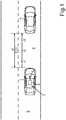
- a road situation is shown, in which a motor vehicle 1 according to an embodiment of the invention is on a road 2.
- the motor vehicle 1 includes a driver assistance system 3, which is formed as a semi-automatic braking system in the embodiment.
- the driver assistance system 3 includes a camera 4 as a sensor device as well as an electronic control device 5 in the form of a digital signal processor and/or microcontroller.
- the control device 5 is electrically coupled to the camera 4.
- the camera 4 is for example a CCD camera or a CMOS camera. It is a video camera, which is able to capture a plurality of frames per second.
- the camera 4 is a front camera providing images of an environmental region 6 in direction of travel in front of the motor vehicle 1.
- the control device 5 can provide at least one functionality in the motor vehicle 1, which serves for preventing a collision with an object, in particular with a preceding vehicle 7.
- this functionality can include automatic deceleration and/or the output of warning signals in the motor vehicle 1.
- the control device 5 can detect the object 7 and determine a distance d to the object 7 (to the preceding vehicle 7).
- another sensor device can also be used, such as for example an infrared sensor and/or a lidar sensor and/or a radar sensor.
- the control device 5 can determine the current time to collision TTC. This time to collision TTC represents a risk level and thus the risk of collision with the vehicle 7. If a risk is recognized, thus, various safety measures can then be taken and thus different functionalities can be provided.
- different points of time t1, t2, t3 can be determined.
- three different groups of functionalities can be defined, which are provided at different points of time t1, t2, t3 before a theoretical collision with the vehicle 7.
- This second group of functionalities can include the following measures:
- the following functionalities can be associated with this third group:
- a first step S1 the camera 4 provides image data of the environmental region 6 and communicates the image data to the control device 5.
- the control device 5 determines a stimulus intensity I of the object 7, thus an intensity, with which the object 7 affects the optical perception of the driver, based on the current image data.
- a visibility or a visibility level of the object 7 is determined as the stimulus intensity I. This visibility level is determined depending on the following parameters:
- the visibility level can basically be determined in any manner, for example also according to the method as it is described in the document Joulan, K. et al "Contrast Sensitivity Functions for Road Visibility Estimation on Digital Images", IFSTTAR, Paris, France .
- the control device 5 calculates the reaction time RT of the driver depending on the stimulus intensity I.
- RT denotes the reaction time to be determined
- I denotes the stimulus intensity and therefore the visibility level of the object 7.
- R 0 , ⁇ and ⁇ are parameters, which can be adjusted in the operation or preset as a constant.
- the calculation of the reaction time RT is accordingly effected according to the Piéron's law, which describes the dependence of the reaction time RT on the stimulus intensity I.
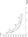
- This dependence is represented in Fig. 3 , wherein the reaction time RT is plotted on the y axis and the stimulus intensity I (visibility level) is plotted on the x axis.
- the reaction time RT is the lower, the larger the visibility level of the object 7 is. Therein, the differences in the reaction time RT can even be greater than 100 ms.
- the current brightness level of the environmental region 6 is also taken into account.
- the above mentioned parameter ⁇ is adjusted.
- Fig. 3 three different ranges of the curve for three different brightness levels of the environmental region 6 are illustrated, namely for photopic vision PS (day vision), for mesopic vision MS (low brightness level, but no darkness) as well as for scotopic vision SS (very low brightness level).
- reaction time RT can optionally also be calculated depending on at least one characteristic of the driver.
- it can be differentiated between currently determined characteristics on the one hand as well as fixed characteristics on the other hand.
- fixed characteristic for example, the age and/or the vision can be taken into account.
- the current fatigue level and/or the current concentration level of the driver can be determined in the operation as variable characteristics. The characteristics of the driver can then for example influence the parameters ⁇ and R 0 .
- a step S4 the current velocity v of the motor vehicle 1 is determined.
- a road condition of the road 2 is determined. It can for example be determined based on the environmental conditions, which are determined based on the image data of the camera 4.
- the detection of the object 7 is effected, namely for example of a preceding vehicle.
- the control device 5 determines the TTC and furthermore checks whether or not collision with the object 7 is imminent at all. If a collision currently is not imminent (for example, if the object 7 is outside of the trajectory of the motor vehicle 1), thus, the method ends in a step S8. If a possible collision is identified, thus, the above mentioned points of time t1, t2, t3 are set depending on the reaction time RT as well as on the road condition, namely in the steps S9, S10 and S11.
- the dependence on the reaction time RT is in that with greater reaction time RT the respective functionalities are provided earlier (with greater TTC) than with a lower reaction time RT.
- This dependence can for example be a linear dependence.
Landscapes
- Engineering & Computer Science (AREA)
- Automation & Control Theory (AREA)
- Transportation (AREA)
- Mechanical Engineering (AREA)
- Human Computer Interaction (AREA)
- Traffic Control Systems (AREA)
- Control Of Driving Devices And Active Controlling Of Vehicle (AREA)
Description
- The invention relates to a method for providing a functionality by means of a driver assistance system of a motor vehicle. In an environmental region of the motor vehicle, an object is detected based on sensor data of a sensor device of the driver assistance system. A current distance of the object from the motor vehicle is determined, and a point of time for providing the functionality is determined depending on the current distance. In addition, the invention relates to a driver assistance system for performing such a method as well as to a motor vehicle with a driver assistance system.
- Driver assistance systems for motor vehicles are already known from the prior art in various configuration. Presently, the interest is directed to a driver assistance system serving for avoiding collisions of the motor vehicle with other objects such as for example with another motor vehicle. In particular, a driver assistance system is concerned, which is formed for automatically decelerating the motor vehicle due to a determined risk. In such systems, the distance to an obstacle, typically to a preceding vehicle located in front of the motor vehicle, is sensed by means of a sensor device. Depending on the measured distance, then, a level of risk is determined, in particular the so-called "time to collision" (TTC). Depending on the TTC, then, an automatic braking operation of the motor vehicle can be initiated, if applicable, and/or other measures can be taken, such as for example outputting an acoustic and/or optical and/or haptic warning signal. If the TTC falls below a preset threshold, at least one of the mentioned functionalities is provided.
- In the prior art, it is differentiated between fully automatic systems on the one hand as well as semi-autonomous systems on the other hand. In fully autonomous systems, the braking operation is completely controlled by the driver assistance system without the driver having to intervene. The vehicle is decelerated such that collision does not occur. In contrast, in semi-autonomous systems, the motor vehicle is only partially decelerated by the driver assistance system, and additionally an optical and/or haptic and/or acoustic warning signal is output to the driver. Then, the driver himself can complete the braking operation and completely decelerate the motor vehicle by means of the brake pedal or else allow that the driver assistance system reduces the impact energy upon the collision with the obstacle. In addition, systems are known, in which exclusively warning signals are output.
- In particular in semi-autonomous systems, the reaction time of the driver presents a substantial role. Namely, the overall stopping distance that the motor vehicle travels until standstill is composed of a reaction distance on the one hand and the braking distance on the other hand. Therein, the reaction distance denotes the distance the motor vehicle travels during the period of time that the driver requires to recognize and resist the dangerous situation, to operate the brake pedal. In contrast, the braking distance denotes the distance that the motor vehicle travels during the time from pressing the brake pedal until standstill. Thus, it becomes apparent that the overall stopping distance not only depends on the braking distance of the motor vehicle, but rather also depends on the reaction time of the driver.
- From the document
DE 42 01 970 A1 , a driver assistance system for motor vehicles is known, which serves for supporting guidance in case of poor visibility conditions, in particular in case of fog. A detecting device determines the presence of an obstacle with the aid of infrared radiation. The driver assistance system also has a measuring device determining the range of the detecting device for sensing the obstacle with the current visibility conditions. By means of a signal evaluation device, a warning signal or else a braking signal for decelerating the motor vehicle is output upon sensing the obstacle from the currently determined range. - Further prior art is known from
EP 1 642 769 A1claim 1. - It is an object of the invention to demonstrate a solution how in a method of the initially mentioned kind, the point of time for providing the functionality can be determined depending on the respectively current situation such that collision with the object can be prevented as possible, but the functionality also is not provided too soon.
- According to the invention, this object is solved by a method, by a driver assistance system as well as by a motor vehicle having the features according to the respective independent claims. Advantageous implementations of the invention are the subject matter of the dependent claims, of the description and of the figures.
- A method according to the invention serves for providing a functionality by means of a driver assistance system of a motor vehicle. For example, automatic deceleration can be initiated and/or a warning signal can be output as the functionality. Based on sensor data of a sensor device of the driver assistance system, an object is detected in an environmental region of the motor vehicle, such as for example a preceding vehicle. Based on the sensor data, the current distance to the object is also determined.
- Depending on the current distance, a point of time for providing the functionality is set. According to the invention, it is provided that a reaction time of a driver is determined, which the driver requires for carrying out a maneuver or for taking an action due to the object, and that the point of time for providing the functionality is determined depending on the reaction time of the driver.
- The method according to the invention allows providing the functionality at an optimum point of time considering the reaction time of the driver. On the one hand, thus, the functionality can be provided as timely as collision with the object can be prevented. On the other hand, provision of the functionality too soon and thus impairment of the driving comfort is also prevented. Therein, the reaction time of the driver depends on very different parameters, such as for example the object photometry (contrast) and/or the road geometry and/or atmospheric conditions (fog and/or rain) and/or on the brightness level of the environment. Such parameters can for example be determined based on image data of a camera. However, the reaction time is also dependent on characteristics of the driver, such as for example the age and/or the current fatigue and/or the current level of concentration of the driver. If a too great reaction time is overall determined, thus, the functionality can be provided earlier than with a lower reaction time, such that the driver still has enough time to take corresponding actions.
- Therein, a time interval is understood by the reaction time, which the driver needs to recognize the dangerous situation - namely the object - and to take a corresponding action such as for example actuating the brake pedal. This reaction time affects the reaction path, which overall results in the mentioned stopping distance together with the braking distance of the motor vehicle.
- As point of time for providing the functionality, preferably, a limit value for the time to collision TTC is understood. If the TTC falls below this limit value, thus, the functionality is provided.
- According to the invention, the reaction time of the driver is determined according to the Pieron's law. Therein, the Pieron's law describes the dependence of the reaction time on a variable indicating the cognitive ability of the driver with respect to the object. According to the Pieron's law, the reaction time of the driver can be particularly precisely determined depending on situation, namely in particular depending on the current environmental conditions and the like.
- Therein, a stimulus intensity of the object is preferably determined for the driver, and the reaction time is determined depending on this stimulus intensity according to the Piéron's law. Therein, the stimulus intensity is the intensity, with which the object affects the optical perception of the driver or with which the driver is able to optically perceive the object. This stimulus intensity affects the reaction time of the driver to a great extent such that the reaction time can be determined depending on the stimulus intensity with very high accuracy.
- Preferably, a visibility level of the object can be determined as stimulus intensity, which can be determined in particular based on image data of a camera and/or based on sensor data of an infrared sensor and/or based on sensor data of a lidar sensor. The scientific literature has already addressed the determination of the visibility level of objects based on digital image data. The determination of the visibility level of an object is for example described in the following document: Joulan, K. et al "Contrast Sensitivity Functions for Road Visibility Estimation on Digital Images", IFSTTAR, Paris, France.
- In an embodiment, the visibility level of the object is determined depending on at least one of the following parameters: Depending on an object photometry, in particular a contrast of the object with respect to the background (can for example be determined based on images of a camera) and/or depending on atmospheric conditions in the environmental region of the motor vehicle and/or depending on a road geometry and/or depending on the presence of a road infrastructure. Therein, the object photometry is dependent on an optical contrast of the object relative to the background. The larger this contrast is, the better the object can be perceived by the driver and the less the reaction time of the driver is. Within the scope of the determination of atmospheric conditions, preferably, a distance is determined, up to which an object can be perceived and recognized by the driver at all with the existing atmospheric conditions. The road geometry also has some influence on the perception of the object by the driver. The presence of a road infrastructure such as for example a guardrail and/or an acoustic baffle can also influence the visibility of the object. Namely, the object can be covered by a road infrastructure at least in certain areas.
- The stimulus intensity - in particular as the visibility level of the object - is preferably determined based on image data of a camera and/or based on sensor data of an infrared sensor and/or based on sensor data of a lidar sensor. In particular the determination of the stimulus intensity based on image data provides for high accuracy in determining the reaction time of the driver. Generally overall, the stimulus intensity can be determined based on sensor data of an optical sensor.
- The detection of the object in the environmental region of the motor vehicle can also be effected based on image data of a camera and/or based on sensor data of an infrared sensor and/or based on sensor data of a lidar sensor. Generally overall, the object can be detected based on sensor data of an optical sensor.
- The detection of the object is preferably effected by means of one and the same sensor device, by means of which the stimulus intensity is also determined. This sensor device can preferably be an optical sensor device.
- It proves advantageous if the reaction time is calculated according to the following formula:

- Preferably, it is provided that the reaction time is determined depending on a brightness level of the environmental region. Therein, the brightness level can also be determined based on image data of a camera. If the above mentioned formula is used for calculating the reaction time, thus, the parameter α can be adjusted depending on the brightness level of the environmental region. It can be differentiated between three brightness levels, namely between scotopic vision, mesopic vision and photopic vision. Depending on the current brightness level of the environment, then, the parameter α is correspondingly adapted. This allows the calculation of the reaction time depending on the current brightness level of the environment and accordingly with high accuracy.
- In an embodiment, it can also be provided that the reaction time is determined depending on at least one characteristic of the driver. This characteristic can be optionally sensed in the operation of the vehicle and/or it can be stored in the driver assistance system. As the characteristic of the driver, for example, the age (can be stored) and/or the current fatigue level (can be sensed in the operation) and/or the current concentration level (can also be sensed) can be taken into account. Methods for sensing the fatigue level and the concentration level of the driver are already known from the prior art. If the above formula is used, thus, these characteristics optionally can affect the remaining parameters R0 and/or β. Thus, the reaction time is not only dependent on the external conditions thus independent of the driver himself, but additionally also on the specific driver currently driving the motor vehicle. The accuracy of the determination of the reaction time can therefore be further increased.
- The provision of the functionality by means of the driver assistance system can include that the motor vehicle is at least partially automatically decelerated and/or a warning signal is output in the interior of the vehicle by means of an electronic output device. Preferably, the driver assistance system is a semi-automatic braking system, by means of which interventions in the braking system of the motor vehicle can be performed and/or a warning signal can be output to the driver.
- For determining the point of time for providing the functionality, a current road condition of the roadway can also be determined. The point of time for providing the functionality can then be determined depending on the current road condition. The current road condition can in particular be determined based on image data of a camera. Therein, first, atmospheric conditions can be determined, and it can be determined if the motor vehicle is driven in fog and/or rain. Depending on these atmospheric conditions, then, the road condition can be inferred, in particular to the effect whether or not currently a slippery roadway is present and thus whether or not danger of slipping currently exists. This too can affect the determination of the optimum point of time for providing the functionality. Namely, the road condition has a great influence on the braking distance of the motor vehicle.
- Furthermore, the invention relates to a driver assistance system for a motor vehicle, wherein the system is formed for performing a method according to the invention.
- A motor vehicle according to the invention includes a driver assistance system according to the invention.
- The preferred embodiments presented with respect to the method according to the invention and the advantages thereof correspondingly apply to the system according to the invention as well as to the motor vehicle according to the invention.
- Now, the invention is explained in more detail based on a preferred embodiment as well as with reference to the attached drawings.
- There show:
- Fig. 1
- in schematic illustration a road situation with a motor vehicle according to an embodiment of the invention;
- Fig. 2
- a flow diagram of a method according to an embodiment of the invention; and
- Fig. 3
- a dependence of a reaction time on a stimulus intensity according to the Piéron's law.
- In
Fig. 1 , a road situation is shown, in which amotor vehicle 1 according to an embodiment of the invention is on aroad 2. Themotor vehicle 1 includes adriver assistance system 3, which is formed as a semi-automatic braking system in the embodiment. Thedriver assistance system 3 includes acamera 4 as a sensor device as well as anelectronic control device 5 in the form of a digital signal processor and/or microcontroller. Thecontrol device 5 is electrically coupled to thecamera 4. - The
camera 4 is for example a CCD camera or a CMOS camera. It is a video camera, which is able to capture a plurality of frames per second. Thecamera 4 is a front camera providing images of anenvironmental region 6 in direction of travel in front of themotor vehicle 1. - The
control device 5 can provide at least one functionality in themotor vehicle 1, which serves for preventing a collision with an object, in particular with a precedingvehicle 7. For example, this functionality can include automatic deceleration and/or the output of warning signals in themotor vehicle 1. - Based on image data of the
camera 4, thecontrol device 5 can detect theobject 7 and determine a distance d to the object 7 (to the preceding vehicle 7). For determining the distance d, optionally, another sensor device can also be used, such as for example an infrared sensor and/or a lidar sensor and/or a radar sensor. - From the distance d, the
control device 5 can determine the current time to collision TTC. This time to collision TTC represents a risk level and thus the risk of collision with thevehicle 7. If a risk is recognized, thus, various safety measures can then be taken and thus different functionalities can be provided. - For providing different functionalities, therein, different points of time t1, t2, t3 can be determined. In the embodiment, three different groups of functionalities can be defined, which are provided at different points of time t1, t2, t3 before a theoretical collision with the
vehicle 7. These groups can be defined as follows:
The first group of functionalities can be provided at the time t1 (if TTC = t1 of if TTC > t2). This group can include the following functionalities: - improvement of the visibility by turning on an additional light source, in particular a headlight,
- activation of a windshield wiper, and
- preparation of a strategy for further procedure.
- A second group of functionalities can be provided at the point of time TTC = t2 (or if t3 < TTC < t2). This second group of functionalities can include the following measures:
- outputting a warning signal to the driver, for example an optical and/or acoustic and/or haptic warning signal,
- operating the braking system and thus initiating an automatic braking operation, as well as
- determining possible maneuvers for preventing the collision.
- The third group of functionalities can be provided at the point of time t3 (TTC = t3). The following functionalities can be associated with this third group:
- automatic emergency braking of the
motor vehicle 1 by means of thecontrol device 5, as well as - performing the previously determined maneuvers for preventing the collision.
- These points of time t1, t2, t3 are set depending on a determined reaction time RT of the driver. This current reaction time RT can for example be continuously determined and thus "online" in the operation of the
driver assistance system 3. A method according to an embodiment of the invention is now explained in more detail with reference toFig. 2 . - In a first step S1, the
camera 4 provides image data of theenvironmental region 6 and communicates the image data to thecontrol device 5. In a second step S2, thecontrol device 5 determines a stimulus intensity I of theobject 7, thus an intensity, with which theobject 7 affects the optical perception of the driver, based on the current image data. Therein, a visibility or a visibility level of theobject 7 is determined as the stimulus intensity I. This visibility level is determined depending on the following parameters: - depending on a contrast of the object with respect to the background determined based on the image data,
- depending on current atmospheric conditions in the
environmental region 6 determined based on the image data (fog, rain and the like), as well as - optionally depending on a road geometry and/or the presence of a road infrastructure.
- However, the visibility level can basically be determined in any manner, for example also according to the method as it is described in the document Joulan, K. et al "Contrast Sensitivity Functions for Road Visibility Estimation on Digital Images", IFSTTAR, Paris, France.
- In a further step S3, the
control device 5 calculates the reaction time RT of the driver depending on the stimulus intensity I. This reaction time RT is calculated according to the following formula:
- Therein, RT denotes the reaction time to be determined, while I denotes the stimulus intensity and therefore the visibility level of the
object 7. R0, α and β are parameters, which can be adjusted in the operation or preset as a constant. - The calculation of the reaction time RT is accordingly effected according to the Piéron's law, which describes the dependence of the reaction time RT on the stimulus intensity I. This dependence is represented in
Fig. 3 , wherein the reaction time RT is plotted on the y axis and the stimulus intensity I (visibility level) is plotted on the x axis. As is apparent fromFig. 3 , the reaction time RT is the lower, the larger the visibility level of theobject 7 is. Therein, the differences in the reaction time RT can even be greater than 100 ms. - In determining the reaction time RT according to step S3, the current brightness level of the
environmental region 6 is also taken into account. Depending on the brightness level of the environment, the above mentioned parameter α is adjusted. Therein, inFig. 3 , three different ranges of the curve for three different brightness levels of theenvironmental region 6 are illustrated, namely for photopic vision PS (day vision), for mesopic vision MS (low brightness level, but no darkness) as well as for scotopic vision SS (very low brightness level). - In addition, the reaction time RT can optionally also be calculated depending on at least one characteristic of the driver. Herein, it can be differentiated between currently determined characteristics on the one hand as well as fixed characteristics on the other hand. As fixed characteristic, for example, the age and/or the vision can be taken into account. In contrast, the current fatigue level and/or the current concentration level of the driver can be determined in the operation as variable characteristics. The characteristics of the driver can then for example influence the parameters β and R0.
- With reference again to
Fig. 2 , in a step S4, the current velocity v of themotor vehicle 1 is determined. In a step S5, a road condition of theroad 2 is determined. It can for example be determined based on the environmental conditions, which are determined based on the image data of thecamera 4. In a step S6, the detection of theobject 7 is effected, namely for example of a preceding vehicle. - In a further step S7, the
control device 5 determines the TTC and furthermore checks whether or not collision with theobject 7 is imminent at all. If a collision currently is not imminent (for example, if theobject 7 is outside of the trajectory of the motor vehicle 1), thus, the method ends in a step S8. If a possible collision is identified, thus, the above mentioned points of time t1, t2, t3 are set depending on the reaction time RT as well as on the road condition, namely in the steps S9, S10 and S11. - At the point of time t1, thus if TTC = t1, then, the provision of the first group G1 of functionalities is effected according to step S12. According to step S13, at the point of time t2 (if TTC = t2), the provision of the second group G2 of functionalities is effected. Correspondingly, at the point of time t3 (TTC = t3), the provision of the third group G3 of functionalities is effected in the step S14.
- Therein, the dependence on the reaction time RT is in that with greater reaction time RT the respective functionalities are provided earlier (with greater TTC) than with a lower reaction time RT. This dependence can for example be a linear dependence.
Claims (11)
- Method for providing a functionality by means of a driver assistance system (3) of a motor vehicle (1), comprising the steps of:- detecting an object (7) in an environmental region (6) of the motor vehicle (1) based on sensor data of a sensor device (4) of the driver assistance system (3),- determining a current distance (d) of the object (7) from the motor vehicle (1), and- determining a point of time (t1, t2, t3) for providing the functionality depending on the current distance (d),- determining a reaction time (RT) of a driver, which the driver requires for taking an action due to the object (7) while the point of time (t1, t2, t3) for providing the functionality is determined depending on the reaction time (RT),wherein the object (7) is detected based on image data of a camera and/or based on sensor data of an infrared sensor and/or based on sensor data of a lidar sensor as the sensor device (4)
characterized in that
the reaction time (RT) of the driver is determined according to the Pieron's law. - Method according to claim 1,
characterized in that
a stimulus intensity (I) of the object (7) for the driver is determined, and the reaction time (RT) is determined depending on the stimulus intensity (I). - Method according to claim 2,
characterized in that
as the stimulus intensity (I) a visibility level of the object (7) is determined, which is determined depending on at least one of the following parameters:- depending on an object photometry, in particular a contrast of the object (7) with respect to a background, and/or- depending on atmospheric conditions in the environmental region (6) of the motor vehicle (1), and/or- depending on a road geometry and/or the presence of a road infrastructure. - Method according to claim 2 or 3,
characterized in that
the stimulus intensity (I) is determined based on image data of a camera and/or based on sensor data of an infrared sensor and/or based on sensor data of a lidar sensor as the sensor device (4). - Method according to anyone of the preceding claims,
characterized in that
the reaction time (RT) is calculated according to the following formula:
- Method according to anyone of the preceding claims,
characterized in that
the reaction time (RT) is determined depending on a brightness level of the environmental region (6). - Method according to anyone of the preceding claims,
characterized in that
the reaction time (RT) is determined depending on at least one characteristic of the driver, in particular depending on the age and/or on a current fatigue level and/or on a current concentration level of the driver. - Method according to anyone of the preceding claims,
characterized in that
the provision of the functionality by means of the driver assistance system (3) includes that the motor vehicle (1) is at least partially automatically decelerated and/or a warning signal is output by means of an electronic output device. - Method according to anyone of the preceding claims,
characterized in that
by means of the driver assistance system (3), in particular based on image data of a camera (4), a current road condition is determined, and the point of time (t1, t2, t3) for providing the functionality is determined depending on the current road condition. - Driver assistance system (3) for a motor vehicle (1), wherein the driver assistance system (3) is formed for performing a method according to anyone of the preceding claims.
- Motor vehicle (1) with a driver assistance system (3) according to claim 10.
Applications Claiming Priority (2)
| Application Number | Priority Date | Filing Date | Title |
|---|---|---|---|
| DE102012025468.7A DE102012025468A1 (en) | 2012-12-28 | 2012-12-28 | A method for determining a time for providing functionality by means of a driver assistance system of a motor vehicle, driver assistance system and motor vehicle |
| PCT/EP2013/077688 WO2014102190A2 (en) | 2012-12-28 | 2013-12-20 | Method for determining a point of time for providing a functionality by means of a driver assistance system of a motor vehicle, driver assistance system and motor vehicle |
Publications (2)
| Publication Number | Publication Date |
|---|---|
| EP2938526A2 EP2938526A2 (en) | 2015-11-04 |
| EP2938526B1 true EP2938526B1 (en) | 2019-04-24 |
Family
ID=49956145
Family Applications (1)
| Application Number | Title | Priority Date | Filing Date |
|---|---|---|---|
| EP13821104.0A Active EP2938526B1 (en) | 2012-12-28 | 2013-12-20 | Method for determining a point of time for providing a functionality by means of a driver assistance system of a motor vehicle, driver assistance system and motor vehicle |
Country Status (3)
| Country | Link |
|---|---|
| EP (1) | EP2938526B1 (en) |
| DE (1) | DE102012025468A1 (en) |
| WO (1) | WO2014102190A2 (en) |
Families Citing this family (9)
| Publication number | Priority date | Publication date | Assignee | Title |
|---|---|---|---|---|
| DE102015104890A1 (en) * | 2015-03-30 | 2016-10-06 | Gpi Gesellschaft Für Prüfstanduntersuchungen Und Ingenieurdienstleistungen Mbh | Test system and test method for testing a vehicle and / or vehicle driver specific signal perception and response and configuration system and configuration method for vehicle and / or vehicle driver specific configuration of at least one driver system interface |
| FR3047713A1 (en) * | 2016-02-11 | 2017-08-18 | Valeo Comfort & Driving Assistance | ANTI-COLLISION DEVICE AND METHOD FOR A MOTOR VEHICLE |
| DE102017210219B4 (en) * | 2017-06-20 | 2025-02-13 | Audi Ag | Method for assisting a user of a motor vehicle in avoiding an obstacle, driver assistance device, and motor vehicle |
| DE102018221241A1 (en) * | 2018-12-07 | 2020-06-10 | Volkswagen Aktiengesellschaft | Driver assistance system for a motor vehicle, motor vehicle and method for operating a motor vehicle |
| DE102019218952A1 (en) * | 2019-12-05 | 2021-06-10 | Robert Bosch Gmbh | Method for outputting a warning signal to a driver of a vehicle, computer program and driver assistance system in a vehicle for outputting a warning signal to a driver of the vehicle |
| DE102020207990B4 (en) | 2020-06-29 | 2022-05-05 | Volkswagen Aktiengesellschaft | Method for operating a driver assistance system and driver assistance system |
| DE102020130267A1 (en) | 2020-11-17 | 2022-05-19 | Valeo Schalter Und Sensoren Gmbh | Improvements to the automatic detection of a braking condition |
| CN113335274B (en) * | 2021-07-06 | 2022-11-01 | 山东大学 | Vehicle collision avoidance warning method and system based on braking distance |
| DE102022112104A1 (en) | 2022-05-13 | 2023-11-16 | Zf Cv Systems Global Gmbh | Method and device for preventing an ego vehicle from colliding with a vehicle in front, as well as vehicle and electronic processing unit |
Family Cites Families (9)
| Publication number | Priority date | Publication date | Assignee | Title |
|---|---|---|---|---|
| DE4201970A1 (en) | 1991-01-22 | 1992-08-27 | Iris Gmbh Infrared & Intellige | Driver guide system for motor vehicle, esp. for use in fog - indicates pressure of obstruction, e.g. vehicle, ahead detected from infrared emissions and takes account of prevailing visibility conditions |
| DE10132386A1 (en) * | 2001-07-06 | 2003-01-16 | Volkswagen Ag | Driver assistance system |
| DE10148539A1 (en) * | 2001-10-01 | 2003-04-10 | Volkswagen Ag | Driver assistance method for helping a driver in critical conflict or collision situations, involves determining triggering point for initiation of avoidance measures so that the driver is given adequate time to respond himself |
| DE102004047484A1 (en) * | 2004-09-30 | 2006-04-13 | Robert Bosch Gmbh | Procedure for issuing parking instructions |
| DE102005021141A1 (en) * | 2005-05-06 | 2006-11-09 | Bayerische Motoren Werke Ag | Avoiding injury or damage when opening vehicle doors, by varying trip point or intensity of warning or door braking signal based on attentiveness of occupants |
| US7551991B2 (en) * | 2006-03-07 | 2009-06-23 | Tdk Corporation | Vehicle over speed indicator |
| DE102006057278A1 (en) * | 2006-12-05 | 2008-06-12 | Robert Bosch Gmbh | Method for the possibility of adapting the driving situation of a vehicle run by a driver |
| DE102007018517A1 (en) * | 2007-04-19 | 2008-10-23 | Bayerische Motoren Werke Aktiengesellschaft | Driving condition e.g. view movement, complexity signaling method for car, involves deriving complexity measure as quantitative measure for complexity of driving conditions, and quantitatively delivering complexity measure |
| DE102010031038A1 (en) * | 2010-07-07 | 2012-01-12 | Robert Bosch Gmbh | Method for assisting a driver of a motor vehicle |
-
2012
- 2012-12-28 DE DE102012025468.7A patent/DE102012025468A1/en not_active Withdrawn
-
2013
- 2013-12-20 EP EP13821104.0A patent/EP2938526B1/en active Active
- 2013-12-20 WO PCT/EP2013/077688 patent/WO2014102190A2/en not_active Ceased
Non-Patent Citations (1)
| Title |
|---|
| None * |
Also Published As
| Publication number | Publication date |
|---|---|
| WO2014102190A2 (en) | 2014-07-03 |
| EP2938526A2 (en) | 2015-11-04 |
| WO2014102190A3 (en) | 2014-12-24 |
| DE102012025468A1 (en) | 2014-07-03 |
Similar Documents
| Publication | Publication Date | Title |
|---|---|---|
| WO2014102190A2 (en) | Method for determining a point of time for providing a functionality by means of a driver assistance system of a motor vehicle, driver assistance system and motor vehicle | |
| EP2923912B1 (en) | Driver intention estimation arrangement | |
| US10155515B2 (en) | Travel control device | |
| EP3342661B1 (en) | Sensor integration based pedestrian detection and pedestrian collision prevention apparatus and method | |
| US11427221B2 (en) | Method and control device for the autonomous emergency braking of an ego vehicle | |
| EP2759449B1 (en) | Vehicle control apparatus | |
| US8868326B2 (en) | Method for detecting critical driving situations of lorries or passenger vehicles and method for avoiding collisions | |
| EP2623387B1 (en) | Driving support apparatus and driving support method | |
| US11180164B2 (en) | Vehicle control apparatus, vehicle, and control method | |
| US9357180B2 (en) | Vehicle driving assist device | |
| EP2085281B1 (en) | Driver condition detecting device, in-vehicle alarm system and drive assistance system | |
| EP2618108A1 (en) | Driver assisting system | |
| US20130345900A1 (en) | Travel assist apparatus and travel assist method | |
| JP5401961B2 (en) | Steering support device | |
| US20100131155A1 (en) | Method and device for detecting an obstacle in a region surrounding a motor vehicle, and motor vehicle | |
| CN104599530A (en) | Driver assistance system for a motor vehicle | |
| CN101941399A (en) | Vehicle lane change auxiliary device and auxiliary judgment method thereof | |
| KR101545054B1 (en) | Driver assistance systems and controlling method for the same | |
| CN112721806A (en) | Method and device for assisting blind zone of gradient road section | |
| CN111717196A (en) | Driving safety auxiliary device based on visual analysis | |
| WO2020020525A1 (en) | Method for performing an overtaking maneuver including considering a safety distance, analyzing component, driver assistance system, as well as vehicle | |
| CN109484287B (en) | Automobile braking prompting method and system | |
| JP2014172490A (en) | Driving assisting device for vehicle | |
| US20250242801A1 (en) | Travel control device and method for vehicle | |
| KR20180039838A (en) | Alarm controlling device of vehicle and method thereof |
Legal Events
| Date | Code | Title | Description |
|---|---|---|---|
| PUAI | Public reference made under article 153(3) epc to a published international application that has entered the european phase |
Free format text: ORIGINAL CODE: 0009012 |
|
| 17P | Request for examination filed |
Effective date: 20150616 |
|
| AK | Designated contracting states |
Kind code of ref document: A2 Designated state(s): AL AT BE BG CH CY CZ DE DK EE ES FI FR GB GR HR HU IE IS IT LI LT LU LV MC MK MT NL NO PL PT RO RS SE SI SK SM TR |
|
| AX | Request for extension of the european patent |
Extension state: BA ME |
|
| RIN1 | Information on inventor provided before grant (corrected) |
Inventor name: HAUTIERE, NICOLAS Inventor name: ROBERT-LANDRY, CAROLINE Inventor name: AUBERT, DIDIER Inventor name: BREMOND, ROLAND Inventor name: JOULAN, KARINE |
|
| DAX | Request for extension of the european patent (deleted) | ||
| GRAP | Despatch of communication of intention to grant a patent |
Free format text: ORIGINAL CODE: EPIDOSNIGR1 |
|
| STAA | Information on the status of an ep patent application or granted ep patent |
Free format text: STATUS: GRANT OF PATENT IS INTENDED |
|
| INTG | Intention to grant announced |
Effective date: 20181114 |
|
| GRAS | Grant fee paid |
Free format text: ORIGINAL CODE: EPIDOSNIGR3 |
|
| GRAA | (expected) grant |
Free format text: ORIGINAL CODE: 0009210 |
|
| STAA | Information on the status of an ep patent application or granted ep patent |
Free format text: STATUS: THE PATENT HAS BEEN GRANTED |
|
| AK | Designated contracting states |
Kind code of ref document: B1 Designated state(s): AL AT BE BG CH CY CZ DE DK EE ES FI FR GB GR HR HU IE IS IT LI LT LU LV MC MK MT NL NO PL PT RO RS SE SI SK SM TR |
|
| REG | Reference to a national code |
Ref country code: GB Ref legal event code: FG4D |
|
| REG | Reference to a national code |
Ref country code: CH Ref legal event code: EP |
|
| REG | Reference to a national code |
Ref country code: DE Ref legal event code: R096 Ref document number: 602013054409 Country of ref document: DE |
|
| REG | Reference to a national code |
Ref country code: AT Ref legal event code: REF Ref document number: 1123778 Country of ref document: AT Kind code of ref document: T Effective date: 20190515 Ref country code: IE Ref legal event code: FG4D |
|
| REG | Reference to a national code |
Ref country code: NL Ref legal event code: MP Effective date: 20190424 |
|
| REG | Reference to a national code |
Ref country code: LT Ref legal event code: MG4D |
|
| PG25 | Lapsed in a contracting state [announced via postgrant information from national office to epo] |
Ref country code: NL Free format text: LAPSE BECAUSE OF FAILURE TO SUBMIT A TRANSLATION OF THE DESCRIPTION OR TO PAY THE FEE WITHIN THE PRESCRIBED TIME-LIMIT Effective date: 20190424 |
|
| PG25 | Lapsed in a contracting state [announced via postgrant information from national office to epo] |
Ref country code: FI Free format text: LAPSE BECAUSE OF FAILURE TO SUBMIT A TRANSLATION OF THE DESCRIPTION OR TO PAY THE FEE WITHIN THE PRESCRIBED TIME-LIMIT Effective date: 20190424 Ref country code: NO Free format text: LAPSE BECAUSE OF FAILURE TO SUBMIT A TRANSLATION OF THE DESCRIPTION OR TO PAY THE FEE WITHIN THE PRESCRIBED TIME-LIMIT Effective date: 20190724 Ref country code: LT Free format text: LAPSE BECAUSE OF FAILURE TO SUBMIT A TRANSLATION OF THE DESCRIPTION OR TO PAY THE FEE WITHIN THE PRESCRIBED TIME-LIMIT Effective date: 20190424 Ref country code: HR Free format text: LAPSE BECAUSE OF FAILURE TO SUBMIT A TRANSLATION OF THE DESCRIPTION OR TO PAY THE FEE WITHIN THE PRESCRIBED TIME-LIMIT Effective date: 20190424 Ref country code: ES Free format text: LAPSE BECAUSE OF FAILURE TO SUBMIT A TRANSLATION OF THE DESCRIPTION OR TO PAY THE FEE WITHIN THE PRESCRIBED TIME-LIMIT Effective date: 20190424 Ref country code: PT Free format text: LAPSE BECAUSE OF FAILURE TO SUBMIT A TRANSLATION OF THE DESCRIPTION OR TO PAY THE FEE WITHIN THE PRESCRIBED TIME-LIMIT Effective date: 20190824 Ref country code: SE Free format text: LAPSE BECAUSE OF FAILURE TO SUBMIT A TRANSLATION OF THE DESCRIPTION OR TO PAY THE FEE WITHIN THE PRESCRIBED TIME-LIMIT Effective date: 20190424 Ref country code: AL Free format text: LAPSE BECAUSE OF FAILURE TO SUBMIT A TRANSLATION OF THE DESCRIPTION OR TO PAY THE FEE WITHIN THE PRESCRIBED TIME-LIMIT Effective date: 20190424 |
|
| PG25 | Lapsed in a contracting state [announced via postgrant information from national office to epo] |
Ref country code: BG Free format text: LAPSE BECAUSE OF FAILURE TO SUBMIT A TRANSLATION OF THE DESCRIPTION OR TO PAY THE FEE WITHIN THE PRESCRIBED TIME-LIMIT Effective date: 20190724 Ref country code: LV Free format text: LAPSE BECAUSE OF FAILURE TO SUBMIT A TRANSLATION OF THE DESCRIPTION OR TO PAY THE FEE WITHIN THE PRESCRIBED TIME-LIMIT Effective date: 20190424 Ref country code: PL Free format text: LAPSE BECAUSE OF FAILURE TO SUBMIT A TRANSLATION OF THE DESCRIPTION OR TO PAY THE FEE WITHIN THE PRESCRIBED TIME-LIMIT Effective date: 20190424 Ref country code: RS Free format text: LAPSE BECAUSE OF FAILURE TO SUBMIT A TRANSLATION OF THE DESCRIPTION OR TO PAY THE FEE WITHIN THE PRESCRIBED TIME-LIMIT Effective date: 20190424 Ref country code: GR Free format text: LAPSE BECAUSE OF FAILURE TO SUBMIT A TRANSLATION OF THE DESCRIPTION OR TO PAY THE FEE WITHIN THE PRESCRIBED TIME-LIMIT Effective date: 20190725 |
|
| REG | Reference to a national code |
Ref country code: AT Ref legal event code: MK05 Ref document number: 1123778 Country of ref document: AT Kind code of ref document: T Effective date: 20190424 |
|
| PG25 | Lapsed in a contracting state [announced via postgrant information from national office to epo] |
Ref country code: IS Free format text: LAPSE BECAUSE OF FAILURE TO SUBMIT A TRANSLATION OF THE DESCRIPTION OR TO PAY THE FEE WITHIN THE PRESCRIBED TIME-LIMIT Effective date: 20190824 |
|
| REG | Reference to a national code |
Ref country code: DE Ref legal event code: R097 Ref document number: 602013054409 Country of ref document: DE |
|
| PG25 | Lapsed in a contracting state [announced via postgrant information from national office to epo] |
Ref country code: SK Free format text: LAPSE BECAUSE OF FAILURE TO SUBMIT A TRANSLATION OF THE DESCRIPTION OR TO PAY THE FEE WITHIN THE PRESCRIBED TIME-LIMIT Effective date: 20190424 Ref country code: DK Free format text: LAPSE BECAUSE OF FAILURE TO SUBMIT A TRANSLATION OF THE DESCRIPTION OR TO PAY THE FEE WITHIN THE PRESCRIBED TIME-LIMIT Effective date: 20190424 Ref country code: AT Free format text: LAPSE BECAUSE OF FAILURE TO SUBMIT A TRANSLATION OF THE DESCRIPTION OR TO PAY THE FEE WITHIN THE PRESCRIBED TIME-LIMIT Effective date: 20190424 Ref country code: EE Free format text: LAPSE BECAUSE OF FAILURE TO SUBMIT A TRANSLATION OF THE DESCRIPTION OR TO PAY THE FEE WITHIN THE PRESCRIBED TIME-LIMIT Effective date: 20190424 Ref country code: CZ Free format text: LAPSE BECAUSE OF FAILURE TO SUBMIT A TRANSLATION OF THE DESCRIPTION OR TO PAY THE FEE WITHIN THE PRESCRIBED TIME-LIMIT Effective date: 20190424 Ref country code: RO Free format text: LAPSE BECAUSE OF FAILURE TO SUBMIT A TRANSLATION OF THE DESCRIPTION OR TO PAY THE FEE WITHIN THE PRESCRIBED TIME-LIMIT Effective date: 20190424 |
|
| PG25 | Lapsed in a contracting state [announced via postgrant information from national office to epo] |
Ref country code: IT Free format text: LAPSE BECAUSE OF FAILURE TO SUBMIT A TRANSLATION OF THE DESCRIPTION OR TO PAY THE FEE WITHIN THE PRESCRIBED TIME-LIMIT Effective date: 20190424 Ref country code: SM Free format text: LAPSE BECAUSE OF FAILURE TO SUBMIT A TRANSLATION OF THE DESCRIPTION OR TO PAY THE FEE WITHIN THE PRESCRIBED TIME-LIMIT Effective date: 20190424 |
|
| PLBE | No opposition filed within time limit |
Free format text: ORIGINAL CODE: 0009261 |
|
| STAA | Information on the status of an ep patent application or granted ep patent |
Free format text: STATUS: NO OPPOSITION FILED WITHIN TIME LIMIT |
|
| PG25 | Lapsed in a contracting state [announced via postgrant information from national office to epo] |
Ref country code: TR Free format text: LAPSE BECAUSE OF FAILURE TO SUBMIT A TRANSLATION OF THE DESCRIPTION OR TO PAY THE FEE WITHIN THE PRESCRIBED TIME-LIMIT Effective date: 20190424 |
|
| 26N | No opposition filed |
Effective date: 20200127 |
|
| PG25 | Lapsed in a contracting state [announced via postgrant information from national office to epo] |
Ref country code: SI Free format text: LAPSE BECAUSE OF FAILURE TO SUBMIT A TRANSLATION OF THE DESCRIPTION OR TO PAY THE FEE WITHIN THE PRESCRIBED TIME-LIMIT Effective date: 20190424 |
|
| REG | Reference to a national code |
Ref country code: CH Ref legal event code: PL |
|
| REG | Reference to a national code |
Ref country code: BE Ref legal event code: MM Effective date: 20191231 |
|
| PG25 | Lapsed in a contracting state [announced via postgrant information from national office to epo] |
Ref country code: MC Free format text: LAPSE BECAUSE OF FAILURE TO SUBMIT A TRANSLATION OF THE DESCRIPTION OR TO PAY THE FEE WITHIN THE PRESCRIBED TIME-LIMIT Effective date: 20190424 |
|
| PG25 | Lapsed in a contracting state [announced via postgrant information from national office to epo] |
Ref country code: IE Free format text: LAPSE BECAUSE OF NON-PAYMENT OF DUE FEES Effective date: 20191220 Ref country code: LU Free format text: LAPSE BECAUSE OF NON-PAYMENT OF DUE FEES Effective date: 20191220 |
|
| PG25 | Lapsed in a contracting state [announced via postgrant information from national office to epo] |
Ref country code: LI Free format text: LAPSE BECAUSE OF NON-PAYMENT OF DUE FEES Effective date: 20191231 Ref country code: BE Free format text: LAPSE BECAUSE OF NON-PAYMENT OF DUE FEES Effective date: 20191231 Ref country code: CH Free format text: LAPSE BECAUSE OF NON-PAYMENT OF DUE FEES Effective date: 20191231 |
|
| PG25 | Lapsed in a contracting state [announced via postgrant information from national office to epo] |
Ref country code: CY Free format text: LAPSE BECAUSE OF FAILURE TO SUBMIT A TRANSLATION OF THE DESCRIPTION OR TO PAY THE FEE WITHIN THE PRESCRIBED TIME-LIMIT Effective date: 20190424 |
|
| PG25 | Lapsed in a contracting state [announced via postgrant information from national office to epo] |
Ref country code: HU Free format text: LAPSE BECAUSE OF FAILURE TO SUBMIT A TRANSLATION OF THE DESCRIPTION OR TO PAY THE FEE WITHIN THE PRESCRIBED TIME-LIMIT; INVALID AB INITIO Effective date: 20131220 Ref country code: MT Free format text: LAPSE BECAUSE OF FAILURE TO SUBMIT A TRANSLATION OF THE DESCRIPTION OR TO PAY THE FEE WITHIN THE PRESCRIBED TIME-LIMIT Effective date: 20190424 |
|
| PG25 | Lapsed in a contracting state [announced via postgrant information from national office to epo] |
Ref country code: MK Free format text: LAPSE BECAUSE OF FAILURE TO SUBMIT A TRANSLATION OF THE DESCRIPTION OR TO PAY THE FEE WITHIN THE PRESCRIBED TIME-LIMIT Effective date: 20190424 |
|
| P01 | Opt-out of the competence of the unified patent court (upc) registered |
Effective date: 20230528 |
|
| PGFP | Annual fee paid to national office [announced via postgrant information from national office to epo] |
Ref country code: GB Payment date: 20251229 Year of fee payment: 13 |
|
| PGFP | Annual fee paid to national office [announced via postgrant information from national office to epo] |
Ref country code: FR Payment date: 20251230 Year of fee payment: 13 |
|
| PGFP | Annual fee paid to national office [announced via postgrant information from national office to epo] |
Ref country code: DE Payment date: 20251231 Year of fee payment: 13 |