EP2938499B1 - Printer with improved paper board - Google Patents
Printer with improved paper board Download PDFInfo
- Publication number
- EP2938499B1 EP2938499B1 EP12813382.4A EP12813382A EP2938499B1 EP 2938499 B1 EP2938499 B1 EP 2938499B1 EP 12813382 A EP12813382 A EP 12813382A EP 2938499 B1 EP2938499 B1 EP 2938499B1
- Authority
- EP
- European Patent Office
- Prior art keywords
- printer
- paper board
- free end
- root
- half paper
- Prior art date
- Legal status (The legal status is an assumption and is not a legal conclusion. Google has not performed a legal analysis and makes no representation as to the accuracy of the status listed.)
- Not-in-force
Links
Images


Classifications
-
- B—PERFORMING OPERATIONS; TRANSPORTING
- B41—PRINTING; LINING MACHINES; TYPEWRITERS; STAMPS
- B41J—TYPEWRITERS; SELECTIVE PRINTING MECHANISMS, i.e. MECHANISMS PRINTING OTHERWISE THAN FROM A FORME; CORRECTION OF TYPOGRAPHICAL ERRORS
- B41J11/00—Devices or arrangements of selective printing mechanisms, e.g. ink-jet printers or thermal printers, for supporting or handling copy material in sheet or web form
- B41J11/0045—Guides for printing material
-
- B—PERFORMING OPERATIONS; TRANSPORTING
- B41—PRINTING; LINING MACHINES; TYPEWRITERS; STAMPS
- B41J—TYPEWRITERS; SELECTIVE PRINTING MECHANISMS, i.e. MECHANISMS PRINTING OTHERWISE THAN FROM A FORME; CORRECTION OF TYPOGRAPHICAL ERRORS
- B41J13/00—Devices or arrangements of selective printing mechanisms, e.g. ink-jet printers or thermal printers, specially adapted for supporting or handling copy material in short lengths, e.g. sheets
- B41J13/10—Sheet holders, retainers, movable guides, or stationary guides
- B41J13/103—Sheet holders, retainers, movable guides, or stationary guides for the sheet feeding section
-
- B—PERFORMING OPERATIONS; TRANSPORTING
- B65—CONVEYING; PACKING; STORING; HANDLING THIN OR FILAMENTARY MATERIAL
- B65H—HANDLING THIN OR FILAMENTARY MATERIAL, e.g. SHEETS, WEBS, CABLES
- B65H1/00—Supports or magazines for piles from which articles are to be separated
- B65H1/04—Supports or magazines for piles from which articles are to be separated adapted to support articles substantially horizontally, e.g. for separation from top of pile
-
- B—PERFORMING OPERATIONS; TRANSPORTING
- B65—CONVEYING; PACKING; STORING; HANDLING THIN OR FILAMENTARY MATERIAL
- B65H—HANDLING THIN OR FILAMENTARY MATERIAL, e.g. SHEETS, WEBS, CABLES
- B65H2402/00—Constructional details of the handling apparatus
- B65H2402/30—Supports; Subassemblies; Mountings thereof
- B65H2402/31—Pivoting support means
-
- B—PERFORMING OPERATIONS; TRANSPORTING
- B65—CONVEYING; PACKING; STORING; HANDLING THIN OR FILAMENTARY MATERIAL
- B65H—HANDLING THIN OR FILAMENTARY MATERIAL, e.g. SHEETS, WEBS, CABLES
- B65H2402/00—Constructional details of the handling apparatus
- B65H2402/40—Details of frames, housings or mountings of the whole handling apparatus
- B65H2402/46—Table apparatus
-
- B—PERFORMING OPERATIONS; TRANSPORTING
- B65—CONVEYING; PACKING; STORING; HANDLING THIN OR FILAMENTARY MATERIAL
- B65H—HANDLING THIN OR FILAMENTARY MATERIAL, e.g. SHEETS, WEBS, CABLES
- B65H2405/00—Parts for holding the handled material
- B65H2405/10—Cassettes, holders, bins, decks, trays, supports or magazines for sheets stacked substantially horizontally
- B65H2405/11—Parts and details thereof
- B65H2405/111—Bottom
- B65H2405/1116—Bottom with means for changing geometry
- B65H2405/11164—Rear portion extensible in parallel to transport direction
- B65H2405/111646—Rear portion extensible in parallel to transport direction involving extension members pivotable around an axis parallel to bottom surface and perpendicular to transport direction
-
- B—PERFORMING OPERATIONS; TRANSPORTING
- B65—CONVEYING; PACKING; STORING; HANDLING THIN OR FILAMENTARY MATERIAL
- B65H—HANDLING THIN OR FILAMENTARY MATERIAL, e.g. SHEETS, WEBS, CABLES
- B65H2405/00—Parts for holding the handled material
- B65H2405/10—Cassettes, holders, bins, decks, trays, supports or magazines for sheets stacked substantially horizontally
- B65H2405/11—Parts and details thereof
- B65H2405/111—Bottom
- B65H2405/1117—Bottom pivotable, e.g. around an axis perpendicular to transport direction, e.g. arranged at rear side of sheet support
- B65H2405/11172—Bottom pivotable, e.g. around an axis perpendicular to transport direction, e.g. arranged at rear side of sheet support around an axis perpendicular to both transport direction and surface of sheets
-
- B—PERFORMING OPERATIONS; TRANSPORTING
- B65—CONVEYING; PACKING; STORING; HANDLING THIN OR FILAMENTARY MATERIAL
- B65H—HANDLING THIN OR FILAMENTARY MATERIAL, e.g. SHEETS, WEBS, CABLES
- B65H2405/00—Parts for holding the handled material
- B65H2405/30—Other features of supports for sheets
- B65H2405/32—Supports for sheets partially insertable - extractable, e.g. upon sliding movement, drawer
- B65H2405/324—Supports for sheets partially insertable - extractable, e.g. upon sliding movement, drawer between operative position and non operative position
-
- B—PERFORMING OPERATIONS; TRANSPORTING
- B65—CONVEYING; PACKING; STORING; HANDLING THIN OR FILAMENTARY MATERIAL
- B65H—HANDLING THIN OR FILAMENTARY MATERIAL, e.g. SHEETS, WEBS, CABLES
- B65H2701/00—Handled material; Storage means
- B65H2701/10—Handled articles or webs
- B65H2701/19—Specific article or web
- B65H2701/1912—Banknotes, bills and cheques or the like
-
- B—PERFORMING OPERATIONS; TRANSPORTING
- B65—CONVEYING; PACKING; STORING; HANDLING THIN OR FILAMENTARY MATERIAL
- B65H—HANDLING THIN OR FILAMENTARY MATERIAL, e.g. SHEETS, WEBS, CABLES
- B65H2801/00—Application field
- B65H2801/03—Image reproduction devices
- B65H2801/06—Office-type machines, e.g. photocopiers
Definitions
- the present invention relates to a printer or the like having an improved paper board which is configured for resisting to shocks and/or loads.
- printer should be intended as including any peripheral device to be connected (by any means, such as through a cable, a wireless link, an infrared link or the like) to a computer, a personal computer, a smart phone or the like and configured for managing sheets.
- Examples of "printer” are: a printer for printing one single sheet of paper or a plurality of sheets of paper connected together; a printer for printing a sheet of material other than paper; a scanner, a facsimile machine or any multi-function machine which comprises one or more of the above functionalities.
- printers which are designed for private use or use by a rather reduced number of people as in a small office are generally rather compact in size because they are intended to be supported on a desk or table in proximity of the computer of the user.
- a printer comprises a paper board for supporting the sheet(s) to be printed and/or the sheet(s) which has/have been printed.
- a printer which is intended to be used by a single user or by a limited number of users, just because it needs to be as compact as possible, comprises a movable or removable paper board.
- Such a movable or removable paper board can be arranged in a working position where it indeed supports the sheet(s) during the printer operation and projects outwardly from the shape of the printer at the opening which receives the sheets to be printed or outputs the printed sheets.
- the movable or removable paper board can be also arranged in a rest position corresponding to a non working position of the printer. In the rest position, typically, the paper board becomes retracted or inset and it does not substantially project outwardly from the shape of the printer.
- the rest position of the paper board is provided in order to save space in the area where the printer is installed when the printer is not in use. In addition, when the paper board is in the rest position, it is more protected and prevented from becoming damaged.
- US2006/0001209 A1 relates to a printer having a paper sheet output tray configured so as to be freely pulled out from or put in the paper sheet outlet.
- US 6 428 000 B1 discloses a sheet tray of image forming apparatus.
- JP 2011 236022 A discloses a medium support and recording device.
- EP 1 595 708 A1 discloses a medium supplying apparatus and image forming apparatus.
- JP H05 40232 U , JP 2000 016667 A and JP H07 315665 disclose background arrangements.
- the Applicant has noticed that when the paper board of a known printer is extracted and projects outwardly it may be subjected to shocks, mainly to unintentional pressures and vertical loads. Such pressures, typically loads directed downwardly, may damage the paper board and render it no more usable. In some cases, the paper board may become broken and it should be replaced by a new paper board.
- the Applicant has tackled the problem of providing a printer with a paper board which is more robust and which may resist to certain types of shocks and loads, typically substantially unintentional vertical loads.
- a paper board of a printer may be rendered more resistant to shocks and loads by providing such a paper board with at least one free end part which is movable with respect to a root part when it is subject to such shocks and loads; profitably, in absence of shocks and loads, the at least one free end part cooperates with the root part for providing a substantially continuous support surface.
- the present invention relates to a printer comprising an opening through which one or more sheets to be treated could be introduced therein and further comprising a paper board for supporting said one or more sheets to be treated, wherein said paper board comprises two half paper boards, wherein each half paper board comprises a root and a free end, wherein each free end is rotatable about a respective horizontal axis with respect to said root when it is subject to a vertical load, wherein said root and said free end are connected through a resilient means maintaining a top surface of the free end substantially at the same level of a top surface of the root when loaded with a load corresponding to a predetermined number of sheets, and wherein each half paper board is rotatable about a respective vertical axis from a fully retracted configuration to a fully extended configuration.
- the at least one root and the at least one free end are connected through a resilient means.
- the resilient means may comprise a spring or a rubber element.
- the two half paper boards are jointly rotatable so that rotation of one half paper board results in corresponding rotation of the other paper board.
- the printer may further comprising a magnetic device for attracting at least one of said two half paper boards towards a body of the printer.
- the magnetic device may comprise a magnet and a ferromagnetic element.
- the printer further comprises a microswitch for detecting the paper board in a rest configuration.
- the printer is a dot-matrix printer and is configured for being used in a bank, a post office or the like.
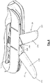
- FIG. 1 schematically shows a printer 1 according to an embodiment of the present invention.
- the printer 1 comprises a main body 11, possibly made of a plastic material, typically containing mechanical mechanisms (not shown), electric and electronic devices (not shown), printing arrangements and/or reading/detecting devices (not shown) for reading images and/or written matter on a sheet provided to the printer.
- Mechanical mechanisms comprise any known arrangement for transporting one or more sheets (typically at least partially made of paper) from feeding opening 12 to an output opening or back to the feeding opening 12.
- Electric and electronic devices comprise any electric device or apparatus for providing power to the printer and for providing the full operation of the printer as it is known in the art.
- the printer 1 may comprise known printing arrangements for printing images and/or written matter on a sheet provided to the printer.
- Such printing arrangements may comprise laser printing devices, ink-jet printing devices, dot-matrix printing devices or a combination thereof.
- the printer 1 may further comprise, possibly in addition to the printing arrangements, known reading/detecting devices for reading images and/or written matter on a sheet provided to the printer.
- reading/detecting devices may comprise optical reading devices, scanners, magnetic reading devices, watermark reading devices or the like.
- the printer 1 which is shown in the Figures may be used in banks, postal offices or the like for printing forms, checks or the like. Preferably, it is based on dot-matrix printing.
- the printer 1 is intended for single use or for use by a limited number of people and is generally arranged on a desk or the like. It is desirable that the printer takes a small area of the desk.
- the printer 1 comprises a feeding opening 12 for admitting one or more sheets in the printer.
- the sheet(s) is(are) supported by a paper board 2 when the sheet(s) is(are) input into the opening 12 and/or are output therefrom.
- the paper board 2 maintains the sheet(s) in a substantially horizontal arrangement.
- the paper board 2 comprises two half paper boards 2A and 2B.
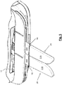
- the two half paper boards 2A, 2B are shaped as to comply with the front shape of the printer. This can be inferred from Figures 1 and 2 .
- Figures 1 and 2 show the two half paper boards 2A, 2B in the fully retracted state.
- the two half paper boards do not substantially project outwardly from the body 11 of the printer 1 and do not provide any support to the sheet(s) to be printed.
- the two half paper boards 2A, 2B are not exposed to (unintentional) damages.
- the two half paper boards 2A, 2B are made of a plastic material.
- the two half paper boards 2A, 2B have a planar top surface, lateral walls which follow the shape of the top surface and a open bottom surface. This is profitable for saving weight, saving plastic material and saving costs.
- the half paper boards 2A, 2B are rotatable from the fully retracted state ( Figures 1 and 2 ) to a fully extended state which is shown in Figure 5 . While the fully retracted state correspond to a rest condition, the fully extended state corresponds to a working condition. In the working condition, the two half paper boards 2A, 2B are close to each other and substantially form a single surface. Because of the rounded end 2A1, 2B1 of the half paper boards, a sort of "V" opening is provided at the ends of the half paper boards when they are in the working condition.
- the two half paper boards 2A, 2B are rotatable about two respective rotation axes XA, XB.
- Rotation axes XA and XB are, preferably, vertical or substantially vertical when the printer is arranged on a horizontal surface.
- the rotation of the two half paper boards 2A, 2B may be coordinated so that rotation of one paper board will cause a corresponding rotation of the other half paper board.
- each half paper board might be independent from the other. Therefore, rotation of one paper board will not cause any corresponding rotation of the other half paper board.
- the rotation of the half paper boards from the rest position is performed by a user (not shown) who gently hangs the rounded edge of one of (or both) the half paper boards with one finger.
- the half paper boards 2A, 2B are accompanied by the user up to the fully extended state of Figure 5 .
- a magnetic device 3 is provided for maintaining the half paper boards in the fully retracted state.
- the magnetic device 3 also operates for attracting the half paper boards in the last part of their retraction travel. Thanks to this magnetic device 3, the risk that a portion (even small) of the half paper boards remains projecting and not fully retracted is highly reduced. This also results in an advantage from aesthetic point of view.
- the magnetic device 3 may comprise, for each half paper board, a magnet 31 connected to the main body of the printer 1 and a ferromagnetic element 32 connected to half paper board in a proper position corresponding to the magnet.
- Figure 3 also shows a microswitch 4 which may be present in embodiments of the present invention. Such a microswitch 4 may detect whether half paper board is in the fully retracted state.
- Figure 3 also shows a portion of paper tray 13 of the printer 1.
- each half paper board 2A, 2B comprises a root 20A, 20B and a free end 21A, 21B.
- the root 20A, 20B is substantially rigid and can not be deflected (over a tolerance which is standard for similar parts).
- each half paper board can be deflected (with respect to the root) when a pressure or vertical load is applied thereon.
- the free end 21A, 21B is rotatable with respect to the fixed root 20A, 20B about a rotational axis YA, YB.
- Rotation of the free end could be mechanically limited to a number of degrees by a stop or the like.
- rotation of the free end 21A, 21B could be limited by the contact of the rounded edge 2A1, 2B1 with the surface where the printer is arranged.
- the root 20A, 20B and the free end 21A, 21B are elastically connected together by a resilient means 22A, 22B.
- a resilient means 22A, 22B could be a spring, a rubber element or the like.
- the arrangement of springs 23A, 23B is shown in Figure 6.1 .
- the resilient means should have enough force for maintaining the top surface of the free end 21A, 21B substantially at the same level of the top surface of the root 20A, 20B.
- the resilient means 22A, 22B is also designed for maintaining the free end substantially horizontal also when loaded with a certain load, typically the load corresponding to a single sheet or to a predetermined number of sheets. A safety margin could be provided so that also a higher number of sheets could be sustained without deflection of the free end with respect to the root.
- the root 20A, 20B has a rather short length. Therefore, the connection between root and free end is at a position which is close to the printer main body 11. In this manner, the line of flexibility is close to the main body and the risk of damages to the paper boards 2A, 2B is further reduced.
- a mechanical arrangement (not shown in the drawings) could be any arrangement which could maintain the free end in a horizontal position when one or a predetermined number of sheets are placed on the paper board.
- the arrangement should be designed so that when a higher load is placed over the free end, it becomes rotated downwardly. Also this solution prevents damages from a (unintentional) rather high load on the paper board.
- this solution is unable to automatically recover to the working position. In fact, when the free end is rotated downwardly, it should be turned back to the working position and blocked in this position by the user. No automatic recover to the working position is provided as in the embodiments provided with a resilient means.
- the rotation of the two half paper boards from the fully retracted state to the fully extended state could be made by automatic mechanisms such as motors.
Description
- The present invention relates to a printer or the like having an improved paper board which is configured for resisting to shocks and/or loads.
- In the present description and claims the term "printer" should be intended as including any peripheral device to be connected (by any means, such as through a cable, a wireless link, an infrared link or the like) to a computer, a personal computer, a smart phone or the like and configured for managing sheets. Examples of "printer" are: a printer for printing one single sheet of paper or a plurality of sheets of paper connected together; a printer for printing a sheet of material other than paper; a scanner, a facsimile machine or any multi-function machine which comprises one or more of the above functionalities.
- In the art, several different designs of printers are known. The difference being at least in the printing technology (laser printing, ink-jet printing, dot-matrix printing, ...) and/or in the main intended use (domestic use, small office use, large companies use, ...). Printers which are designed for private use or use by a rather reduced number of people as in a small office are generally rather compact in size because they are intended to be supported on a desk or table in proximity of the computer of the user.
- Typically, a printer comprises a paper board for supporting the sheet(s) to be printed and/or the sheet(s) which has/have been printed. Typically, a printer which is intended to be used by a single user or by a limited number of users, just because it needs to be as compact as possible, comprises a movable or removable paper board.
- Such a movable or removable paper board can be arranged in a working position where it indeed supports the sheet(s) during the printer operation and projects outwardly from the shape of the printer at the opening which receives the sheets to be printed or outputs the printed sheets.
- The movable or removable paper board can be also arranged in a rest position corresponding to a non working position of the printer. In the rest position, typically, the paper board becomes retracted or inset and it does not substantially project outwardly from the shape of the printer. The rest position of the paper board is provided in order to save space in the area where the printer is installed when the printer is not in use. In addition, when the paper board is in the rest position, it is more protected and prevented from becoming damaged.
-
US2006/0001209 A1 relates to a printer having a paper sheet output tray configured so as to be freely pulled out from or put in the paper sheet outlet. -
US 6 428 000 B1 discloses a sheet tray of image forming apparatus. -
JP 2011 236022 A -
EP 1 595 708 A1 -
JP H05 40232 U JP 2000 016667 A JP H07 315665 - The Applicant has noticed that when the paper board of a known printer is extracted and projects outwardly it may be subjected to shocks, mainly to unintentional pressures and vertical loads. Such pressures, typically loads directed downwardly, may damage the paper board and render it no more usable. In some cases, the paper board may become broken and it should be replaced by a new paper board.
- The replacement of a part of a printer is expensive and may cause stops of normal working. Sometimes it may result in the need to replace the whole printer in view of possible difficulties in obtaining special parts after some times from installation of the printer.
- In view of the above, the Applicant has tackled the problem of providing a printer with a paper board which overcomes the aforesaid drawback.
- In particular, the Applicant has tackled the problem of providing a printer with a paper board which is more robust and which may resist to certain types of shocks and loads, typically substantially unintentional vertical loads.
- The Applicant has observed that a paper board of a printer may be rendered more resistant to shocks and loads by providing such a paper board with at least one free end part which is movable with respect to a root part when it is subject to such shocks and loads; profitably, in absence of shocks and loads, the at least one free end part cooperates with the root part for providing a substantially continuous support surface.
- According to a first aspect, the present invention relates to a printer comprising an opening through which one or more sheets to be treated could be introduced therein and further comprising a paper board for supporting said one or more sheets to be treated,
wherein said paper board comprises two half paper boards, wherein each half paper board comprises a root and a free end,
wherein each free end is rotatable about a respective horizontal axis with respect to said root when it is subject to a vertical load,
wherein said root and said free end are connected through a resilient means maintaining a top surface of the free end substantially at the same level of a top surface of the root when loaded with a load corresponding to a predetermined number of sheets, and
wherein each half paper board is rotatable about a respective vertical axis from a fully retracted configuration to a fully extended configuration. - In preferred embodiments, the at least one root and the at least one free end are connected through a resilient means. The resilient means may comprise a spring or a rubber element.
- In embodiments of the invention, the two half paper boards are jointly rotatable so that rotation of one half paper board results in corresponding rotation of the other paper board.
- The printer may further comprising a magnetic device for attracting at least one of said two half paper boards towards a body of the printer. The magnetic device may comprise a magnet and a ferromagnetic element.
- Preferably, the printer further comprises a microswitch for detecting the paper board in a rest configuration.
- Preferably, the printer is a dot-matrix printer and is configured for being used in a bank, a post office or the like.
- Embodiments of the present invention will be better understood by reading the following detailed description, to be read by referring to the accompanying drawings, wherein:
-
Figure 1 is a view of a printer according to an embodiment of the present invention; -
Figure 2 is a partial front view of the printer ofFigure 1 with paper board retracted; -
Figure 3 shows a microswitch and a magnet of a closure magnetic device; -
Figure 4 is a partial front view of the printer ofFigure 1 with paper board partially extracted; -
Figure 4.1 is a partial front view, partially cut away, of the printer ofFigure 1 which shows rotation of the paper board; -
Figure 5 is a partial front view of the printer ofFigure 1 with paper board fully extracted; -
Figure 6 is a partial front view of the printer ofFigure 1 with paper board fully extracted and subjected to a vertical load; and -
Figure 6.1 shows details of the springs which allow the free ends of the paper board to rotate with respect to the roots. -
Figure 1 schematically shows aprinter 1 according to an embodiment of the present invention. Theprinter 1 comprises amain body 11, possibly made of a plastic material, typically containing mechanical mechanisms (not shown), electric and electronic devices (not shown), printing arrangements and/or reading/detecting devices (not shown) for reading images and/or written matter on a sheet provided to the printer. Mechanical mechanisms comprise any known arrangement for transporting one or more sheets (typically at least partially made of paper) from feeding opening 12 to an output opening or back to thefeeding opening 12. Electric and electronic devices comprise any electric device or apparatus for providing power to the printer and for providing the full operation of the printer as it is known in the art. Theprinter 1 may comprise known printing arrangements for printing images and/or written matter on a sheet provided to the printer. Such printing arrangements may comprise laser printing devices, ink-jet printing devices, dot-matrix printing devices or a combination thereof. Theprinter 1 may further comprise, possibly in addition to the printing arrangements, known reading/detecting devices for reading images and/or written matter on a sheet provided to the printer. Such reading/detecting devices may comprise optical reading devices, scanners, magnetic reading devices, watermark reading devices or the like. - The above details of the
printer 1 will not further described as they are not relevant for the present invention. - The
printer 1 which is shown in the Figures may be used in banks, postal offices or the like for printing forms, checks or the like. Preferably, it is based on dot-matrix printing. Theprinter 1 is intended for single use or for use by a limited number of people and is generally arranged on a desk or the like. It is desirable that the printer takes a small area of the desk. - As it is shown in
Figure 1 , theprinter 1 comprises a feeding opening 12 for admitting one or more sheets in the printer. Profitably, the sheet(s) is(are) supported by a paper board 2 when the sheet(s) is(are) input into theopening 12 and/or are output therefrom. The paper board 2 maintains the sheet(s) in a substantially horizontal arrangement. - According to one embodiment of the present invention, the paper board 2 comprises two
half paper boards half paper boards Figures 1 and2 . -
Figures 1 and2 show the twohalf paper boards body 11 of theprinter 1 and do not provide any support to the sheet(s) to be printed. In this state, profitably, the twohalf paper boards half paper boards half paper boards - The
half paper boards Figures 1 and2 ) to a fully extended state which is shown inFigure 5 . While the fully retracted state correspond to a rest condition, the fully extended state corresponds to a working condition. In the working condition, the twohalf paper boards - As it is shown, in
Figure 4.1 , the twohalf paper boards - The rotation of the two
half paper boards - In other embodiments, each half paper board might be independent from the other. Therefore, rotation of one paper board will not cause any corresponding rotation of the other half paper board.
- Preferably, the rotation of the half paper boards from the rest position is performed by a user (not shown) who gently hangs the rounded edge of one of (or both) the half paper boards with one finger. The
half paper boards Figure 5 . - Passing from the fully extended state (
Figure 5 ) to the fully retracted state (Figures 1 and2 ) will be made by the user through a hand rotation movement of one or twohalf paper boards - According to a preferred embodiment of the present invention (see
Figure 3 ), amagnetic device 3 is provided for maintaining the half paper boards in the fully retracted state. Themagnetic device 3 also operates for attracting the half paper boards in the last part of their retraction travel. Thanks to thismagnetic device 3, the risk that a portion (even small) of the half paper boards remains projecting and not fully retracted is highly reduced. This also results in an advantage from aesthetic point of view. - The
magnetic device 3 may comprise, for each half paper board, amagnet 31 connected to the main body of theprinter 1 and aferromagnetic element 32 connected to half paper board in a proper position corresponding to the magnet. -
Figure 3 also shows amicroswitch 4 which may be present in embodiments of the present invention. Such amicroswitch 4 may detect whether half paper board is in the fully retracted state.Figure 3 also shows a portion ofpaper tray 13 of theprinter 1. - According to the present invention, each
half paper board root free end - The
root - On the other hand, the
free end - In one embodiment, the
free end root free end - Preferably, the
root free end springs Figure 6.1 . The resilient means should have enough force for maintaining the top surface of thefree end root - However, when a pressure higher than a predetermined load is applied to one (or both) half paper board, the free end thereof becomes deflected. This deflection avoids breakage of the half paper board as in printers according to the prior art.
- Preferably, the
root main body 11. In this manner, the line of flexibility is close to the main body and the risk of damages to thepaper boards - While having a root and a free end connected through a resilient means, for instance springs 23A, 23B, is deemed to be advantageous and preferable, they might be also connected together through a mechanical arrangement. Such a mechanical arrangement (not shown in the drawings) could be any arrangement which could maintain the free end in a horizontal position when one or a predetermined number of sheets are placed on the paper board. The arrangement should be designed so that when a higher load is placed over the free end, it becomes rotated downwardly. Also this solution prevents damages from a (unintentional) rather high load on the paper board. However, this solution is unable to automatically recover to the working position. In fact, when the free end is rotated downwardly, it should be turned back to the working position and blocked in this position by the user. No automatic recover to the working position is provided as in the embodiments provided with a resilient means.
- In some embodiments of the invention, not shown in the drawings, the rotation of the two half paper boards from the fully retracted state to the fully extended state (and possibly back to the fully retracted state) could be made by automatic mechanisms such as motors.
Claims (8)
- A printer (1) comprising an opening (12) through which one or more sheets to be treated could be introduced therein and further comprising a paper board (2A, 2B) for supporting said one or more sheets to be treated,wherein said paper board comprises two half paper boards (2A, 2B), wherein each half paper board comprises a root (20A, 20B) and a free end (21A, 21B),wherein each free end (21A, 21B) is rotatable about a respective horizontal axis (YA, YB) with respect to said root (20A, 20B) when it is subject to a vertical load,wherein said root (20A, 20B) and said free end (21A, 21B) are connected through a resilient means maintaining a top surface of the free end (21A, 21B) substantially at the same level of a top surface of the root (20A, 20B) when loaded with a load corresponding to a predetermined number of sheets, andwherein each half paper board (2A, 2B) is rotatable about a respective vertical axis (XA, XB) from a fully retracted configuration to a fully extended configuration.
- The printer (1) of claim 1, wherein said resilient means comprises a spring (23A, 23B).
- The printer (1) of claim 1, wherein said resilient means comprises a rubber element.
- The printer (1) of claim 1, wherein said two half paper boards (2A, 2B) are jointly rotatable so that rotation of one half paper board (2A, 2B) results in corresponding rotation of the other paper board (2B, 2A).
- The printer (1) of any of claims 1 to 4, wherein the printer further comprises a magnetic device for attracting at least one of said two half paper boards (2A, 2B) towards a body of the printer.
- The printer (1) of claim 5, wherein said magnetic device comprises a magnet (31) and a ferromagnetic element (32).
- The printer (1) of any of preceding claims, wherein said printer further comprises a microswitch (4) for detecting the paper board (2A, 2B) in a rest configuration.
- The printer (1) of any of the preceding claims, wherein said printer is a dot-matrix printer and is configured for being used in a bank, a post office or the like.
Applications Claiming Priority (1)
| Application Number | Priority Date | Filing Date | Title |
|---|---|---|---|
| PCT/EP2012/077049 WO2014101950A1 (en) | 2012-12-28 | 2012-12-28 | Printer with improved paper board |
Publications (2)
| Publication Number | Publication Date |
|---|---|
| EP2938499A1 EP2938499A1 (en) | 2015-11-04 |
| EP2938499B1 true EP2938499B1 (en) | 2019-11-27 |
Family
ID=47553039
Family Applications (1)
| Application Number | Title | Priority Date | Filing Date |
|---|---|---|---|
| EP12813382.4A Not-in-force EP2938499B1 (en) | 2012-12-28 | 2012-12-28 | Printer with improved paper board |
Country Status (6)
| Country | Link |
|---|---|
| US (1) | US9387702B2 (en) |
| EP (1) | EP2938499B1 (en) |
| KR (1) | KR102061817B1 (en) |
| CN (1) | CN105102231B (en) |
| CL (1) | CL2015001823A1 (en) |
| WO (1) | WO2014101950A1 (en) |
Families Citing this family (2)
| Publication number | Priority date | Publication date | Assignee | Title |
|---|---|---|---|---|
| JP2018122952A (en) * | 2017-01-30 | 2018-08-09 | ブラザー工業株式会社 | Sheet tray and image forming apparatus |
| RU2749500C1 (en) | 2017-06-15 | 2021-06-11 | Кэнон Кабусики Кайся | Cartridge and electrophotographic imaging apparatus |
Citations (3)
| Publication number | Priority date | Publication date | Assignee | Title |
|---|---|---|---|---|
| JPH0540232U (en) * | 1991-10-29 | 1993-05-28 | 村田機械株式会社 | Paper feeder |
| JPH07315665A (en) * | 1994-05-30 | 1995-12-05 | Nec Eng Ltd | Paper stacker |
| JP2000016667A (en) * | 1998-07-06 | 2000-01-18 | Casio Comput Co Ltd | Printer cover |
Family Cites Families (14)
| Publication number | Priority date | Publication date | Assignee | Title |
|---|---|---|---|---|
| KR100202383B1 (en) * | 1997-01-23 | 1999-06-15 | 윤종용 | Stacker for facsimile |
| JPH11100158A (en) * | 1997-09-29 | 1999-04-13 | Nec Home Electron Ltd | Discharged paper storage mechanism |
| JP3691745B2 (en) * | 1999-12-01 | 2005-09-07 | シャープ株式会社 | Paper tray of image forming device |
| JP3077842U (en) * | 2000-11-21 | 2001-06-08 | 船井電機株式会社 | Paper source and paper tray |
| US6983885B2 (en) * | 2001-06-22 | 2006-01-10 | Seiko Epson Corporation | Print media processing apparatus and control method for the same |
| JP4566781B2 (en) * | 2004-05-14 | 2010-10-20 | 株式会社沖データ | Medium supply apparatus and image forming apparatus |
| JP4315069B2 (en) | 2004-07-02 | 2009-08-19 | 船井電機株式会社 | Printer |
| CN2768619Y (en) * | 2004-12-22 | 2006-04-05 | 董慧 | Drinker with adjustable height cup tray |
| US7472985B2 (en) * | 2005-02-16 | 2009-01-06 | Seiko Epson Corporation | Liquid ejecting apparatus, recording apparatus, absorbing member and ink collecting unit |
| JP2007161369A (en) * | 2005-12-09 | 2007-06-28 | Canon Inc | Recording device |
| JP5061720B2 (en) * | 2007-05-23 | 2012-10-31 | コニカミノルタビジネステクノロジーズ株式会社 | Image forming apparatus |
| US8412091B2 (en) * | 2009-06-19 | 2013-04-02 | Kabushiki Kaisha Toshiba | Image erasing apparatus and method of carrying recording medium in image erasing apparatus |
| CN201587341U (en) * | 2009-12-28 | 2010-09-22 | 好孩子儿童用品有限公司 | Children automobile seat |
| JP5527004B2 (en) * | 2010-05-12 | 2014-06-18 | セイコーエプソン株式会社 | Media support, recording device |
-
2012
- 2012-12-28 WO PCT/EP2012/077049 patent/WO2014101950A1/en active Application Filing
- 2012-12-28 EP EP12813382.4A patent/EP2938499B1/en not_active Not-in-force
- 2012-12-28 US US14/655,255 patent/US9387702B2/en active Active
- 2012-12-28 CN CN201280078170.0A patent/CN105102231B/en not_active Expired - Fee Related
- 2012-12-28 KR KR1020157019099A patent/KR102061817B1/en active IP Right Grant
-
2015
- 2015-06-24 CL CL2015001823A patent/CL2015001823A1/en unknown
Patent Citations (3)
| Publication number | Priority date | Publication date | Assignee | Title |
|---|---|---|---|---|
| JPH0540232U (en) * | 1991-10-29 | 1993-05-28 | 村田機械株式会社 | Paper feeder |
| JPH07315665A (en) * | 1994-05-30 | 1995-12-05 | Nec Eng Ltd | Paper stacker |
| JP2000016667A (en) * | 1998-07-06 | 2000-01-18 | Casio Comput Co Ltd | Printer cover |
Also Published As
| Publication number | Publication date |
|---|---|
| CL2015001823A1 (en) | 2016-01-22 |
| WO2014101950A1 (en) | 2014-07-03 |
| CN105102231A (en) | 2015-11-25 |
| CN105102231B (en) | 2017-12-22 |
| KR20150097668A (en) | 2015-08-26 |
| KR102061817B1 (en) | 2020-01-02 |
| US20150352863A1 (en) | 2015-12-10 |
| US9387702B2 (en) | 2016-07-12 |
| EP2938499A1 (en) | 2015-11-04 |
Similar Documents
| Publication | Publication Date | Title |
|---|---|---|
| US7719730B2 (en) | Image reader for use in an image forming apparatus, and contamination check method of guide film for the same | |
| EP2938499B1 (en) | Printer with improved paper board | |
| JP5826155B2 (en) | Sheet stacking apparatus and image forming apparatus having the same | |
| US20060244208A1 (en) | Sheet discharge tray and a multiple bin sorter equipped with the same | |
| JP2007145541A (en) | Paper feeding device, image recording device, image reading device, and image reading and recording device | |
| JP4159561B2 (en) | Sheet stacking device | |
| JP2014189387A (en) | Sheet feeder and image forming device having the same | |
| JP6004536B2 (en) | Document feeder and image forming apparatus provided with document feeder | |
| JP6042016B2 (en) | Image forming apparatus | |
| JP5960895B2 (en) | Image forming apparatus | |
| JP4166130B2 (en) | Paper feeder for image forming apparatus | |
| JP6284597B2 (en) | Document feeder and image forming apparatus provided with document feeder | |
| JP2010054614A (en) | Image forming apparatus | |
| JP2007217140A (en) | Sheet feeding device and image forming device | |
| JP2007001717A (en) | Sheet delivery tray | |
| US10621479B2 (en) | Illumination source | |
| JP4250484B2 (en) | Sheet feeding apparatus and image forming apparatus provided with the same | |
| JP2008037641A (en) | Paper feeding device and image forming device using the same | |
| JP2011039423A (en) | Image forming apparatus | |
| JP2013225156A (en) | Image forming apparatus | |
| JP2018113691A (en) | Document feeder and image forming apparatus including document feeder | |
| JP2009227448A (en) | Paper feeding device and image forming device | |
| KR20180130959A (en) | The paper sorting device of the Image forming apparatus | |
| KR20070074821A (en) | Multi-function machine | |
| JP2006165638A (en) | Reading/recording apparatus |
Legal Events
| Date | Code | Title | Description |
|---|---|---|---|
| PUAI | Public reference made under article 153(3) epc to a published international application that has entered the european phase |
Free format text: ORIGINAL CODE: 0009012 |
|
| 17P | Request for examination filed |
Effective date: 20150706 |
|
| AK | Designated contracting states |
Kind code of ref document: A1 Designated state(s): AL AT BE BG CH CY CZ DE DK EE ES FI FR GB GR HR HU IE IS IT LI LT LU LV MC MK MT NL NO PL PT RO RS SE SI SK SM TR |
|
| AX | Request for extension of the european patent |
Extension state: BA ME |
|
| DAX | Request for extension of the european patent (deleted) | ||
| RAP1 | Party data changed (applicant data changed or rights of an application transferred) |
Owner name: SHENZHEN PU YING INNOVATION TECHNOLOGY CORPORATION |
|
| STAA | Information on the status of an ep patent application or granted ep patent |
Free format text: STATUS: EXAMINATION IS IN PROGRESS |
|
| 17Q | First examination report despatched |
Effective date: 20181121 |
|
| GRAP | Despatch of communication of intention to grant a patent |
Free format text: ORIGINAL CODE: EPIDOSNIGR1 |
|
| STAA | Information on the status of an ep patent application or granted ep patent |
Free format text: STATUS: GRANT OF PATENT IS INTENDED |
|
| RIC1 | Information provided on ipc code assigned before grant |
Ipc: B65H 1/04 20060101ALI20190605BHEP Ipc: B41J 13/10 20060101AFI20190605BHEP |
|
| INTG | Intention to grant announced |
Effective date: 20190619 |
|
| GRAS | Grant fee paid |
Free format text: ORIGINAL CODE: EPIDOSNIGR3 |
|
| GRAA | (expected) grant |
Free format text: ORIGINAL CODE: 0009210 |
|
| STAA | Information on the status of an ep patent application or granted ep patent |
Free format text: STATUS: THE PATENT HAS BEEN GRANTED |
|
| AK | Designated contracting states |
Kind code of ref document: B1 Designated state(s): AL AT BE BG CH CY CZ DE DK EE ES FI FR GB GR HR HU IE IS IT LI LT LU LV MC MK MT NL NO PL PT RO RS SE SI SK SM TR |
|
| REG | Reference to a national code |
Ref country code: GB Ref legal event code: FG4D |
|
| REG | Reference to a national code |
Ref country code: CH Ref legal event code: EP |
|
| REG | Reference to a national code |
Ref country code: AT Ref legal event code: REF Ref document number: 1206225 Country of ref document: AT Kind code of ref document: T Effective date: 20191215 |
|
| REG | Reference to a national code |
Ref country code: DE Ref legal event code: R096 Ref document number: 602012066069 Country of ref document: DE |
|
| REG | Reference to a national code |
Ref country code: IE Ref legal event code: FG4D |
|
| REG | Reference to a national code |
Ref country code: NL Ref legal event code: MP Effective date: 20191127 |
|
| REG | Reference to a national code |
Ref country code: LT Ref legal event code: MG4D |
|
| PG25 | Lapsed in a contracting state [announced via postgrant information from national office to epo] |
Ref country code: LT Free format text: LAPSE BECAUSE OF FAILURE TO SUBMIT A TRANSLATION OF THE DESCRIPTION OR TO PAY THE FEE WITHIN THE PRESCRIBED TIME-LIMIT Effective date: 20191127 Ref country code: NO Free format text: LAPSE BECAUSE OF FAILURE TO SUBMIT A TRANSLATION OF THE DESCRIPTION OR TO PAY THE FEE WITHIN THE PRESCRIBED TIME-LIMIT Effective date: 20200227 Ref country code: NL Free format text: LAPSE BECAUSE OF FAILURE TO SUBMIT A TRANSLATION OF THE DESCRIPTION OR TO PAY THE FEE WITHIN THE PRESCRIBED TIME-LIMIT Effective date: 20191127 Ref country code: SE Free format text: LAPSE BECAUSE OF FAILURE TO SUBMIT A TRANSLATION OF THE DESCRIPTION OR TO PAY THE FEE WITHIN THE PRESCRIBED TIME-LIMIT Effective date: 20191127 Ref country code: LV Free format text: LAPSE BECAUSE OF FAILURE TO SUBMIT A TRANSLATION OF THE DESCRIPTION OR TO PAY THE FEE WITHIN THE PRESCRIBED TIME-LIMIT Effective date: 20191127 Ref country code: FI Free format text: LAPSE BECAUSE OF FAILURE TO SUBMIT A TRANSLATION OF THE DESCRIPTION OR TO PAY THE FEE WITHIN THE PRESCRIBED TIME-LIMIT Effective date: 20191127 Ref country code: BG Free format text: LAPSE BECAUSE OF FAILURE TO SUBMIT A TRANSLATION OF THE DESCRIPTION OR TO PAY THE FEE WITHIN THE PRESCRIBED TIME-LIMIT Effective date: 20200227 Ref country code: GR Free format text: LAPSE BECAUSE OF FAILURE TO SUBMIT A TRANSLATION OF THE DESCRIPTION OR TO PAY THE FEE WITHIN THE PRESCRIBED TIME-LIMIT Effective date: 20200228 |
|
| PG25 | Lapsed in a contracting state [announced via postgrant information from national office to epo] |
Ref country code: IS Free format text: LAPSE BECAUSE OF FAILURE TO SUBMIT A TRANSLATION OF THE DESCRIPTION OR TO PAY THE FEE WITHIN THE PRESCRIBED TIME-LIMIT Effective date: 20200327 Ref country code: HR Free format text: LAPSE BECAUSE OF FAILURE TO SUBMIT A TRANSLATION OF THE DESCRIPTION OR TO PAY THE FEE WITHIN THE PRESCRIBED TIME-LIMIT Effective date: 20191127 Ref country code: RS Free format text: LAPSE BECAUSE OF FAILURE TO SUBMIT A TRANSLATION OF THE DESCRIPTION OR TO PAY THE FEE WITHIN THE PRESCRIBED TIME-LIMIT Effective date: 20191127 |
|
| PG25 | Lapsed in a contracting state [announced via postgrant information from national office to epo] |
Ref country code: AL Free format text: LAPSE BECAUSE OF FAILURE TO SUBMIT A TRANSLATION OF THE DESCRIPTION OR TO PAY THE FEE WITHIN THE PRESCRIBED TIME-LIMIT Effective date: 20191127 |
|
| REG | Reference to a national code |
Ref country code: DE Ref legal event code: R119 Ref document number: 602012066069 Country of ref document: DE |
|
| PG25 | Lapsed in a contracting state [announced via postgrant information from national office to epo] |
Ref country code: RO Free format text: LAPSE BECAUSE OF FAILURE TO SUBMIT A TRANSLATION OF THE DESCRIPTION OR TO PAY THE FEE WITHIN THE PRESCRIBED TIME-LIMIT Effective date: 20191127 Ref country code: ES Free format text: LAPSE BECAUSE OF FAILURE TO SUBMIT A TRANSLATION OF THE DESCRIPTION OR TO PAY THE FEE WITHIN THE PRESCRIBED TIME-LIMIT Effective date: 20191127 Ref country code: CZ Free format text: LAPSE BECAUSE OF FAILURE TO SUBMIT A TRANSLATION OF THE DESCRIPTION OR TO PAY THE FEE WITHIN THE PRESCRIBED TIME-LIMIT Effective date: 20191127 Ref country code: PT Free format text: LAPSE BECAUSE OF FAILURE TO SUBMIT A TRANSLATION OF THE DESCRIPTION OR TO PAY THE FEE WITHIN THE PRESCRIBED TIME-LIMIT Effective date: 20200419 Ref country code: EE Free format text: LAPSE BECAUSE OF FAILURE TO SUBMIT A TRANSLATION OF THE DESCRIPTION OR TO PAY THE FEE WITHIN THE PRESCRIBED TIME-LIMIT Effective date: 20191127 Ref country code: DK Free format text: LAPSE BECAUSE OF FAILURE TO SUBMIT A TRANSLATION OF THE DESCRIPTION OR TO PAY THE FEE WITHIN THE PRESCRIBED TIME-LIMIT Effective date: 20191127 |
|
| REG | Reference to a national code |
Ref country code: CH Ref legal event code: PL |
|
| REG | Reference to a national code |
Ref country code: BE Ref legal event code: MM Effective date: 20191231 |
|
| PG25 | Lapsed in a contracting state [announced via postgrant information from national office to epo] |
Ref country code: SM Free format text: LAPSE BECAUSE OF FAILURE TO SUBMIT A TRANSLATION OF THE DESCRIPTION OR TO PAY THE FEE WITHIN THE PRESCRIBED TIME-LIMIT Effective date: 20191127 Ref country code: SK Free format text: LAPSE BECAUSE OF FAILURE TO SUBMIT A TRANSLATION OF THE DESCRIPTION OR TO PAY THE FEE WITHIN THE PRESCRIBED TIME-LIMIT Effective date: 20191127 Ref country code: MC Free format text: LAPSE BECAUSE OF FAILURE TO SUBMIT A TRANSLATION OF THE DESCRIPTION OR TO PAY THE FEE WITHIN THE PRESCRIBED TIME-LIMIT Effective date: 20191127 |
|
| REG | Reference to a national code |
Ref country code: AT Ref legal event code: MK05 Ref document number: 1206225 Country of ref document: AT Kind code of ref document: T Effective date: 20191127 |
|
| PLBE | No opposition filed within time limit |
Free format text: ORIGINAL CODE: 0009261 |
|
| STAA | Information on the status of an ep patent application or granted ep patent |
Free format text: STATUS: NO OPPOSITION FILED WITHIN TIME LIMIT |
|
| GBPC | Gb: european patent ceased through non-payment of renewal fee |
Effective date: 20200227 |
|
| PG25 | Lapsed in a contracting state [announced via postgrant information from national office to epo] |
Ref country code: FR Free format text: LAPSE BECAUSE OF NON-PAYMENT OF DUE FEES Effective date: 20200127 Ref country code: IE Free format text: LAPSE BECAUSE OF NON-PAYMENT OF DUE FEES Effective date: 20191228 Ref country code: LU Free format text: LAPSE BECAUSE OF NON-PAYMENT OF DUE FEES Effective date: 20191228 Ref country code: DE Free format text: LAPSE BECAUSE OF NON-PAYMENT OF DUE FEES Effective date: 20200701 |
|
| 26N | No opposition filed |
Effective date: 20200828 |
|
| PG25 | Lapsed in a contracting state [announced via postgrant information from national office to epo] |
Ref country code: LI Free format text: LAPSE BECAUSE OF NON-PAYMENT OF DUE FEES Effective date: 20191231 Ref country code: AT Free format text: LAPSE BECAUSE OF FAILURE TO SUBMIT A TRANSLATION OF THE DESCRIPTION OR TO PAY THE FEE WITHIN THE PRESCRIBED TIME-LIMIT Effective date: 20191127 Ref country code: BE Free format text: LAPSE BECAUSE OF NON-PAYMENT OF DUE FEES Effective date: 20191231 Ref country code: SI Free format text: LAPSE BECAUSE OF FAILURE TO SUBMIT A TRANSLATION OF THE DESCRIPTION OR TO PAY THE FEE WITHIN THE PRESCRIBED TIME-LIMIT Effective date: 20191127 Ref country code: CH Free format text: LAPSE BECAUSE OF NON-PAYMENT OF DUE FEES Effective date: 20191231 Ref country code: PL Free format text: LAPSE BECAUSE OF FAILURE TO SUBMIT A TRANSLATION OF THE DESCRIPTION OR TO PAY THE FEE WITHIN THE PRESCRIBED TIME-LIMIT Effective date: 20191127 |
|
| PG25 | Lapsed in a contracting state [announced via postgrant information from national office to epo] |
Ref country code: GB Free format text: LAPSE BECAUSE OF NON-PAYMENT OF DUE FEES Effective date: 20200227 |
|
| PGFP | Annual fee paid to national office [announced via postgrant information from national office to epo] |
Ref country code: IT Payment date: 20201230 Year of fee payment: 9 |
|
| PG25 | Lapsed in a contracting state [announced via postgrant information from national office to epo] |
Ref country code: CY Free format text: LAPSE BECAUSE OF FAILURE TO SUBMIT A TRANSLATION OF THE DESCRIPTION OR TO PAY THE FEE WITHIN THE PRESCRIBED TIME-LIMIT Effective date: 20191127 |
|
| PG25 | Lapsed in a contracting state [announced via postgrant information from national office to epo] |
Ref country code: HU Free format text: LAPSE BECAUSE OF FAILURE TO SUBMIT A TRANSLATION OF THE DESCRIPTION OR TO PAY THE FEE WITHIN THE PRESCRIBED TIME-LIMIT; INVALID AB INITIO Effective date: 20121228 Ref country code: MT Free format text: LAPSE BECAUSE OF FAILURE TO SUBMIT A TRANSLATION OF THE DESCRIPTION OR TO PAY THE FEE WITHIN THE PRESCRIBED TIME-LIMIT Effective date: 20191127 |
|
| PG25 | Lapsed in a contracting state [announced via postgrant information from national office to epo] |
Ref country code: TR Free format text: LAPSE BECAUSE OF FAILURE TO SUBMIT A TRANSLATION OF THE DESCRIPTION OR TO PAY THE FEE WITHIN THE PRESCRIBED TIME-LIMIT Effective date: 20191127 |
|
| PG25 | Lapsed in a contracting state [announced via postgrant information from national office to epo] |
Ref country code: MK Free format text: LAPSE BECAUSE OF FAILURE TO SUBMIT A TRANSLATION OF THE DESCRIPTION OR TO PAY THE FEE WITHIN THE PRESCRIBED TIME-LIMIT Effective date: 20191127 |
|
| PG25 | Lapsed in a contracting state [announced via postgrant information from national office to epo] |
Ref country code: IT Free format text: LAPSE BECAUSE OF NON-PAYMENT OF DUE FEES Effective date: 20211228 |