EP2938472B1 - Kraftangetriebenes werkzeug, insbesondere sägevorrichtung, mit detektionssystem - Google Patents
Kraftangetriebenes werkzeug, insbesondere sägevorrichtung, mit detektionssystem Download PDFInfo
- Publication number
- EP2938472B1 EP2938472B1 EP13812178.5A EP13812178A EP2938472B1 EP 2938472 B1 EP2938472 B1 EP 2938472B1 EP 13812178 A EP13812178 A EP 13812178A EP 2938472 B1 EP2938472 B1 EP 2938472B1
- Authority
- EP
- European Patent Office
- Prior art keywords
- comparator
- actuating assembly
- output
- swing arm
- pyrotechnic module
- Prior art date
- Legal status (The legal status is an assumption and is not a legal conclusion. Google has not performed a legal analysis and makes no representation as to the accuracy of the status listed.)
- Active
Links
Images



Classifications
-
- B—PERFORMING OPERATIONS; TRANSPORTING
- B23—MACHINE TOOLS; METAL-WORKING NOT OTHERWISE PROVIDED FOR
- B23D—PLANING; SLOTTING; SHEARING; BROACHING; SAWING; FILING; SCRAPING; LIKE OPERATIONS FOR WORKING METAL BY REMOVING MATERIAL, NOT OTHERWISE PROVIDED FOR
- B23D59/00—Accessories specially designed for sawing machines or sawing devices
- B23D59/008—Accessories specially designed for sawing machines or sawing devices comprising computers
-
- B—PERFORMING OPERATIONS; TRANSPORTING
- B23—MACHINE TOOLS; METAL-WORKING NOT OTHERWISE PROVIDED FOR
- B23D—PLANING; SLOTTING; SHEARING; BROACHING; SAWING; FILING; SCRAPING; LIKE OPERATIONS FOR WORKING METAL BY REMOVING MATERIAL, NOT OTHERWISE PROVIDED FOR
- B23D45/00—Sawing machines or sawing devices with circular saw blades or with friction saw discs
- B23D45/06—Sawing machines or sawing devices with circular saw blades or with friction saw discs with a circular saw blade arranged underneath a stationary work-table
- B23D45/065—Sawing machines or sawing devices with circular saw blades or with friction saw discs with a circular saw blade arranged underneath a stationary work-table with the saw blade carried by a pivoted lever
-
- B—PERFORMING OPERATIONS; TRANSPORTING
- B23—MACHINE TOOLS; METAL-WORKING NOT OTHERWISE PROVIDED FOR
- B23D—PLANING; SLOTTING; SHEARING; BROACHING; SAWING; FILING; SCRAPING; LIKE OPERATIONS FOR WORKING METAL BY REMOVING MATERIAL, NOT OTHERWISE PROVIDED FOR
- B23D47/00—Sawing machines or sawing devices working with circular saw blades, characterised only by constructional features of particular parts
- B23D47/08—Sawing machines or sawing devices working with circular saw blades, characterised only by constructional features of particular parts of devices for bringing the circular saw blade to the workpiece or removing same therefrom
-
- B—PERFORMING OPERATIONS; TRANSPORTING
- B23—MACHINE TOOLS; METAL-WORKING NOT OTHERWISE PROVIDED FOR
- B23D—PLANING; SLOTTING; SHEARING; BROACHING; SAWING; FILING; SCRAPING; LIKE OPERATIONS FOR WORKING METAL BY REMOVING MATERIAL, NOT OTHERWISE PROVIDED FOR
- B23D59/00—Accessories specially designed for sawing machines or sawing devices
- B23D59/001—Measuring or control devices, e.g. for automatic control of work feed pressure on band saw blade
-
- B—PERFORMING OPERATIONS; TRANSPORTING
- B27—WORKING OR PRESERVING WOOD OR SIMILAR MATERIAL; NAILING OR STAPLING MACHINES IN GENERAL
- B27G—ACCESSORY MACHINES OR APPARATUS FOR WORKING WOOD OR SIMILAR MATERIALS; TOOLS FOR WORKING WOOD OR SIMILAR MATERIALS; SAFETY DEVICES FOR WOOD WORKING MACHINES OR TOOLS
- B27G19/00—Safety guards or devices specially adapted for wood saws; Auxiliary devices facilitating proper operation of wood saws
- B27G19/02—Safety guards or devices specially adapted for wood saws; Auxiliary devices facilitating proper operation of wood saws for circular saws
-
- G—PHYSICS
- G05—CONTROLLING; REGULATING
- G05B—CONTROL OR REGULATING SYSTEMS IN GENERAL; FUNCTIONAL ELEMENTS OF SUCH SYSTEMS; MONITORING OR TESTING ARRANGEMENTS FOR SUCH SYSTEMS OR ELEMENTS
- G05B19/00—Program-control systems
- G05B19/02—Program-control systems electric
- G05B19/18—Numerical control [NC], i.e. automatically operating machines, in particular machine tools, e.g. in a manufacturing environment, so as to execute positioning, movement or co-ordinated operations by means of program data in numerical form
- G05B19/402—Numerical control [NC], i.e. automatically operating machines, in particular machine tools, e.g. in a manufacturing environment, so as to execute positioning, movement or co-ordinated operations by means of program data in numerical form characterised by control arrangements for positioning, e.g. centring a tool relative to a hole in the workpiece, additional detection means to correct position
-
- G—PHYSICS
- G05—CONTROLLING; REGULATING
- G05B—CONTROL OR REGULATING SYSTEMS IN GENERAL; FUNCTIONAL ELEMENTS OF SUCH SYSTEMS; MONITORING OR TESTING ARRANGEMENTS FOR SUCH SYSTEMS OR ELEMENTS
- G05B2219/00—Program-control systems
- G05B2219/30—Nc systems
- G05B2219/35—Nc in input of data, input till input file format
- G05B2219/35491—Workpiece date display, position, height
-
- Y—GENERAL TAGGING OF NEW TECHNOLOGICAL DEVELOPMENTS; GENERAL TAGGING OF CROSS-SECTIONAL TECHNOLOGIES SPANNING OVER SEVERAL SECTIONS OF THE IPC; TECHNICAL SUBJECTS COVERED BY FORMER USPC CROSS-REFERENCE ART COLLECTIONS [XRACs] AND DIGESTS
- Y10—TECHNICAL SUBJECTS COVERED BY FORMER USPC
- Y10T—TECHNICAL SUBJECTS COVERED BY FORMER US CLASSIFICATION
- Y10T83/00—Cutting
- Y10T83/141—With means to monitor and control operation [e.g., self-regulating means]
-
- Y—GENERAL TAGGING OF NEW TECHNOLOGICAL DEVELOPMENTS; GENERAL TAGGING OF CROSS-SECTIONAL TECHNOLOGIES SPANNING OVER SEVERAL SECTIONS OF THE IPC; TECHNICAL SUBJECTS COVERED BY FORMER USPC CROSS-REFERENCE ART COLLECTIONS [XRACs] AND DIGESTS
- Y10—TECHNICAL SUBJECTS COVERED BY FORMER USPC
- Y10T—TECHNICAL SUBJECTS COVERED BY FORMER US CLASSIFICATION
- Y10T83/00—Cutting
- Y10T83/869—Means to drive or to guide tool
- Y10T83/8821—With simple rectilinear reciprocating motion only
- Y10T83/8858—Fluid pressure actuated
- Y10T83/8863—Explosive fluid
Definitions
- the present disclosure relates to a saw device and more particularly to a saw device, comprising a swing arm movable along a swing arm path between a first swing arm position and a second swing arm position, an actuating assembly configured to transfer a force to the swing arm resulting in a bias on the swing arm in a direction toward the (second) swing arm position, a control system configured to control the actuating assembly and a pyrotechnic module, which is positioned within a cylinder portion of the actuating assembly and activated by passing a firing current through the actuating assembly, such a saw device being known from document US 2005/0268767 A1 , which is considered to represent the closest state of the art.
- a number of power tools have been produced to facilitate forming a work piece into a desired shape.
- One such power tool is a saw device.
- a wide range of saw devices are available for a variety of uses. For example, some saw devices such as cabinet table saws are very heavy and relatively immobile. Other table saws, sometimes referred to as jobsite table saws, are relatively light. Jobsite table saws are thus portable so that a worker can position the table saw at a job site. Some accuracy is typically sacrificed in making a table saw sufficiently light to be mobile. The convenience of locating a table saw at a job site, however, makes job site table saws very desirable in applications such as general construction projects.
- All table saws including cabinet table saws and job site table saws, present a safety concern because the saw blade of the table saw is typically very sharp and moving at a high rate of speed. Accordingly, severe injury such as severed digits and deep lacerations can occur almost instantaneously.
- a number of different safety systems have been developed for table saws in response to the dangers inherent in an exposed blade moving at high speed.
- One such safety system is a blade guard. Blade guards movably enclose the saw blade, thereby providing a physical barrier that must be moved before the rotating blade is exposed. While blade guards are effective to prevent some injuries, the blade guards can be removed by a user either for convenience of using the table saw or because the blade guard is not compatible for use with a particular shaping device.
- a blade guard is typically not compatible with a dado blade and must typically be removed when performing non-through cuts.
- Table saw safety systems have also been developed which are intended to stop the blade when a user's hand approaches or touches the blade.
- Various stopping devices have been developed including braking devices which are physically inserted into the teeth of the blade.
- systems have been developed which physically move the blade or other shaping instrument below the support surface of the device.
- One such device incorporates a swing arm assembly which supports a blade above a work piece support surface and swings the blade beneath the work piece support surface when an unsafe condition is sensed.
- an associated control system must be functional. This is particularly important in systems which incorporate single use devices such as a pyrotechnic charge to move a blade away from a user.
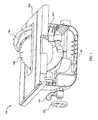
- a saw device 100 is shown with a base housing (not shown) removed.
- the saw device may be, such as, a table saw, a miter saw, a bevel saw, a compound saw, a vertical saw, a stationary saw, a machine saw, a band saw, a jig saw, a chain saw, a circular saw, or other cutting devices with a saw blade.
- the illustrated device as shown in FIG. 1 is a table saw.
- the table saw 100 includes a work piece support surface 104.
- a riving knife or splitter 106 is positioned adjacent to a blade 108 which extends from within the base housing (not shown) to above the work-piece support surface 104.
- a blade guard (not shown) may be attached to the splitter 106.
- the angle of the blade 108 with respect to the work-piece support surface 104 is established by pivoting a frame 114 within the base housing (not shown).
- the frame 114 supports a stop pad 116.
- the frame 114 further supports a carriage assembly 120 shown in FIG. 2 .
- the carriage assembly 120 includes a carriage 122 which supports a motor 124 which is powered through a power switch (not shown) located on the base housing (not shown).
- the carriage 122 is slidably mounted on two guiderails 126/128. The position of the carriage 122 along the guiderails 126/128 is controlled by a blade height turn-wheel 130 through a gearing assembly (not shown) which is connected to a screw post 132.
- the carriage 124 pivotably supports a latch assembly 140 and pivotably supports a swing arm assembly 142.
- the swing arm assembly 142 also shown in FIG. 3 , includes a housing 144.
- a strike bolt 146 is mounted on the housing 144.
- the housing 144 encloses a power wheel 150 that is driven by an output shaft 152 of the motor 124.
- a belt 154 transfers rotational movement from the power wheel 150 to a blade wheel 156.
- a nut 158 is used to affix the blade 108 (not shown in FIGs. 2 and 3 for purpose of clarity) to a shaft 160 of the blade wheel 156.
- a tensioner 162 maintains the belt 154 at a desired tension.
- a solenoid assembly 164 is an actuating assembly which includes a solenoid pin 166 which is aligned with the strike bolt 146 when the swing arm assembly 142 is in a latched position as depicted in FIG. 3 .
- the solenoid assembly 164 in the embodiment of FIGs. 1-3 , is a pyrotechnically activated system wherein a pyrotechnic charge is positioned within a receptacle which in this embodiment is a cylinder portion 170 which is closed at one end by a cap 172. Operation of the solenoid assembly 164 is controlled by a control module 174 which is part of a mitigation and control system 180 depicted in FIG. 4 .
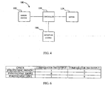
- the mitigation and control system 180 includes a sensing system 182, a controller 184, the motor 124, a detection system 186, and a pyrotechnic module 188.
- the sensing system 182 in different embodiments is any desired sensing circuit.
- One acceptable sensing system is a part of the sensing and control circuit described in U.S. Patent No. 6,922,153 , the entire contents of which are herein incorporated by reference.
- the safety detection and protection system described in the '153 patent senses an unsafe condition and provides a sense signal indicative of the sensed unsafe condition.
- the controller 184 one embodiment comprises a microprocessor, ASIC or other type of processing unit.
- the controller 184 receives the sense signal from the sensor subsystem 182 and, in response to an unsafe condition, fires the pyrotechnic module 188 as discussed more fully below.
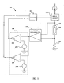
- the detection system 186 is shown in further detail in FIG. 5 .
- the detection system 186 includes a switch 190, a differential block 192, a comparator block 194, and a resistor 196.
- the controller 184, switch 190, differential block 192, comparator block 194, and resistor 196 are located within the mitigation system control module 174 while the pyrotechnic module 188 is located within the cylinder portion 170 of the solenoid assembly 164. Further details of the mitigation and control system 180 are provided in the following description of the operation of the table saw 100.
- the swing arm assembly 142 is maintained in a latched position with the swing arm housing 144 supported by the latch assembly 140 as shown in FIG. 3 .
- the blade wheel 156 is positioned sufficiently close to the work-piece support surface 104 that the blade 108 extends above the work-piece support surface 104 as shown in FIG. 1 .
- a user operates a bevel adjust turn wheel (not shown) to pivot the frame 114 with respect to the work-piece support surface 104 to establish a desired angle between the blade 108 and the work-piece support surface 104.
- the user further operates the blade height adjustment turn-wheel 130 to move the carriage 122 along the guiderails 126/128 to establish a desired height of the blade 108 above the work-piece support surface 104.
- the controller 184 controls the switch element 190 to a closed position thereby applying a voltage from a stable DC power rail to the cylinder portion 170.
- the current also referred to herein as a "test signal” allowed through the switch element 190, typically on the order of milliamps, is selected to be much less than the current required to fire or activate (hereinafter also referred to as a "firing current") the pyrotechnic module 188. Accordingly, if a pyrotechnic module 188 is loaded in the cylinder portion 170, the pyrotechnic module 188 does not fire and a voltage differential is developed across the pyrotechnic module 188.
- the developed voltage difference is applied to the differential amplifier block 192 and an amplified voltage signal based upon the developed voltage difference is provided as an output of the differential amplifier block 192.
- the output of the differential amplifier block 192 is applied to a first comparator 200 which compares the output to a first reference voltage 202.
- the first reference voltage is selected to be slightly lower than the expected lowest output of the differential amplifier block 192 if a pyrotechnic module is positioned within the cylinder portion 170.
- a pyrotechnic module exhibits a range of resistance between 1.7-2.3 ohms, dependent upon temperature.
- the first reference voltage 202 is set to the expected output of the differential amplifier block 192 for a resistance of 1.6 ohms across the cylinder portion 170. Consequently, the first comparator 200 outputs a high value to the controller 184.
- the output of the differential amplifier block 192 is also applied to a second comparator 204 which compares the output to a second reference voltage 206.
- the second reference voltage is selected to be slightly higher than the expected highest output of the differential amplifier block 192 if a pyrotechnic module is positioned within the cylinder portion 170.
- the second reference voltage 206 is set to the expected output of the differential amplifier block 192 for a resistance of 2.4 ohms across the cylinder portion 170. Consequently, the second comparator 204 outputs a high value to the controller 184.
- the controller 184 is configured such that when two high values are received from the comparator block 194, power can be applied to the motor 124. Accordingly, so long as a properly functioning pyrotechnic module 188 is loaded within the cylinder 190, the motor 124 can be energized when the power switch (not shown) is manipulated by a user.
- the voltage drop applied to the differential amplifier block 194 will be much higher than the voltage applied when a pyrotechnic module 188 is loaded.
- the first comparator 200 outputs a high value to the controller 184.
- the second comparator 204 outputs a low value to the controller 184.
- the controller 184 will not allow power to be applied to the motor 124.
- the second comparator 204 Since the second reference voltage 206 is set to the expected output of the differential amplifier block 192 for a resistance of 2.4 ohms across the cylinder portion 170 and the output of the differential amplifier block 192 is subtracted from the second reference voltage 206, the second comparator 204 outputs a high value to the controller 184.
- the controller 184 will not allow power to be applied to the motor 124.
- the mitigation and control system 180 thus ensures that the mitigation system is functional prior to allowing power to be applied to the motor 124. Additionally, in some embodiments the controller 184 is configured to periodically apply the DC rail voltage through the switch element 190 during operation of the motor 124. Accordingly, if the pyrotechnic module 188 becomes dysfunctional during operation of the table saw 100, the power to the motor 124 is interrupted.
- the mitigation and control system 180 verifies that the pyrotechnic module 188 is installed and functional, power is applied to the motor 124 causing the output shaft 152 and the power wheel 150 to rotate. Rotation of the power wheel 150 causes the belt 154 to rotate the blade wheel 156 and the blade 108 which is mounted on the blade wheel 156. A work-piece may then be shaped by moving the work-piece into contact with the blade 108.
- the mitigation and control system 180 monitors for an unsafe condition using the sensor system 182. If an unsafe condition is detected, the controller 184 actuates the pyrotechnic module 188. Upon actuation of the pyrotechnic module 188, the solenoid pin 166 is forced outwardly from the solenoid assembly 164. When the swing arm assembly 142 is maintained in a latched position with the housing 144 supported by the latch assembly 140 as shown in FIG. 3 , the strike bolt 146 is aligned with the solenoid pin 166. Accordingly, as the solenoid pin 166 is forced out of the solenoid assembly 164, the solenoid pin 166 impacts the strike bolt 146.
- the shape of the housing 144 and the latch assembly 140 is selected such that the impact of the solenoid pin 166 on the strike bolt 166 generates a force tending to rotate the latch assembly 140 in the direction of the arrow 210 in FIG. 3 against a spring 212.
- the spring constant of the spring 212 and the force generated by the pyrotechnic module 188 are selected such that when the solenoid pin 166 impacts the strike bolt 146 the generated force is sufficient to compress the spring 212 and to force the latch assembly 140 to rotate into a position whereat the swing arm assembly 142 is no longer maintained in position adjacent to the latch assembly 140. Consequently, the swing arm assembly 142 pivots about the output shaft 152 in the direction of the arrow 214 of FIG.
- the pyrotechnic module 188 Once the pyrotechnic module 188 has fired, the pyrotechnic module 188 no longer provides a path for current to flow. Accordingly, the fired pyrotechnic module 188 is an electrical "open" for the purposes of the detection circuit 186. Consequently, until the pyrotechnic module 188 is replaced, the second comparator 204 outputs a low signal and power is not provided to the motor 124.
- the swing arm assembly 142 is reset by moving the latch assembly 140 out of the swing path. This is effected by compressing the spring 212.
- the swing arm assembly 142 may then be rotated in a counterclockwise direction about the output shaft 152 until the housing 144 is adjacent to the latch assembly 140.
- the latch assembly 140 is then released and the spring 212 biases the latch assembly 140 into contact with the housing 144, returning to the condition of FIG. 3 .
- the table saw 100 thus actively monitors for an unsafe condition and initiates mitigation action automatically in the event an unsafe condition is sensed. Additionally, the table saw 100 ensures that a functional pyrotechnic device 188 is loaded before allowing or continuing to allow energy to be supplied to the motor 124.
- the mitigation system discussed with respect to the table saw 100 can be implemented using very light materials, and is thus amenable to incorporation into a variety of power tools including bench top saws and portable saws.
- the components which are subjected to increased stress within the mitigation system such as the solenoid pin 166, swing arm assembly 142, and the strike bolt 146, can be made of more durable materials including metals to withstand the impacts and stresses of activating the mitigation system.
- Other components, including the housings, may be fabricated from more lightweight materials to minimize the weight of the saw device.
Landscapes
- Engineering & Computer Science (AREA)
- Mechanical Engineering (AREA)
- Life Sciences & Earth Sciences (AREA)
- Wood Science & Technology (AREA)
- Forests & Forestry (AREA)
- Human Computer Interaction (AREA)
- Manufacturing & Machinery (AREA)
- Physics & Mathematics (AREA)
- General Physics & Mathematics (AREA)
- Automation & Control Theory (AREA)
- Sawing (AREA)
Claims (6)
- Sägevorrichtung (100), umfassend:a) einen Schwenkarm (142), der entlang eines Schwenkarmwegs (214) zwischen einer ersten Schwenkarmposition und einer zweiten Schwenkarmposition beweglich ist;b) eine Betätigungsanordnung (164), die ausgestaltet ist, eine Kraft zu dem Schwenkarm zu übertragen, die in einer Vorspannung auf den Schwenkarm in einer Richtung hin zu der zweiten Schwenkarmposition resultiert;c) ein Steuersystem (180), das ausgestaltet ist, die Betätigungsanordnung zu steuern; undd) ein Detektionssystem (186), das ausgestaltet ist, die Betriebsbereitschaft der Betätigungsanordnung mithilfe eines Spannungsabfalls über einen Zylinderabschnitt (170) der Betätigungsanordnung ohne Betätigen der Betätigungsanordnung zu detektieren, der durch Führen eines Prüfstroms durch die Betätigungsanordnung von einer stabilen Gleichstromschiene erzeugt wird; wobeie) wobei das Steuersystem derart ausgestaltet ist, dass einem Motor (124) der Sägevorrichtung kein Strom bereitgestellt wird, wenn das Detektionssystem ein Signal ausgibt, das anzeigt, dass die Betätigungsanordnung nicht betriebsbereit ist;f) wobei die Betätigungsanordnung ein pyrotechnisches Modul (188) umfasst, das in dem Zylinderabschnitt (170) positioniert ist, das durch Führen eines Zündstroms durch die Betätigungsanordnung aktiviert wird;g) wobei das Detektionssystem einen Komparatorblock (194) umfasst;g1) wobei der Komparatorblock ausgestaltet ist, einen ersten Ausgang zu erzeugen, wenn das pyrotechnische Modul in der Betätigungsanordnung installiert ist und der Prüfstrom durch die Betätigungsanordnung geführt wird;g2) wobei der Komparatorblock ausgestaltet ist, einen zweiten Ausgang zu erzeugen, wenn das pyrotechnische Modul als eine Unterbrechung dient oder nicht in der Betätigungsanordnung installiert ist;g3) wobei der Komparatorblock ausgestaltet ist, einen dritten Ausgang zu erzeugen, wenn das pyrotechnische Modul als ein Kurzschluss in der Betätigungsanordnung dient und der Prüfstrom durch die Betätigungsanordnung geführt wird; undg4) wobei jeder des ersten Ausgangs, des zweiten Ausgangs und des dritten Ausgangs unterschiedlich von dem anderen des ersten Ausgangs, des zweiten Ausgangs und des dritten Ausgangs ist.
- Sägevorrichtung nach Anspruch 1, wobei der Komparatorblock umfasst:einen ersten Komparator (200);eine erste Spannungsreferenz (202), die mit dem ersten Komparator wirkverbunden ist;einen zweiten Komparator (204); undeine zweite Spannungsreferenz (206), die mit dem zweiten Komparator wirkverbunden ist.
- Sägevorrichtung nach Anspruch 2, wobei:die erste Spannungsreferenz ausgestaltet ist, ein erstes Referenzsignal an einen ersten Eingang des ersten Komparators anzulegen, das kleiner als das erwartete kleinste Signal ist, das an einen zweiten Eingang des ersten Komparators angelegt wird, wenn das pyrotechnische Modul in der Betätigungsanordnung positioniert ist und ein Prüfsignal an das pyrotechnische Modul angelegt wird; unddie zweite Spannungsreferenz ausgestaltet ist, ein zweites Referenzsignal an einen ersten Eingang des zweiten Komparators anzulegen, das größer als das erwartete höchste Signal ist, das an einen zweiten Eingang des zweiten Komparators angelegt wird, wenn das pyrotechnische Modul in der Betätigungsanordnung positioniert ist und ein Prüfsignal an das pyrotechnische Modul angelegt wird.
- Sägevorrichtung nach Anspruch 3, ferner umfassend:eine Aufnahme (170), die ausgestaltet ist, das pyrotechnische Modul aufzunehmen; undeinen Differenzverstärkerblock (192), der ausgestaltet ist, eine Spannungsdifferenz über die Aufnahme zu detektieren, wenn das Prüfsignal an die Aufnahme angelegt wird, wobei der Differenzverstärkerblock einen Ausgang umfasst, der mit dem zweiten Eingang des ersten Komparators und dem zweiten Eingang des zweiten Komparators wirkverbunden ist.
- Sägevorrichtung nach Anspruch 4, ferner umfassend:ein Schaltelement (190) mit einem Eingang, der mit einer Stromversorgung und einem Ausgang wirkverbunden ist, der mit der Aufnahme wirkverbunden ist; undeine Steuerung (184), die mit einem Ausgang des ersten Komparators und einem Ausgang 10 des zweiten Komparators wirkverbunden ist, wobei die Steuerung mit dem Schaltelement zum gezielten Wirkverbinden der Stromversorgung mit der Aufnahme durch das Schaltelement wirkverbunden ist.
- Sägevorrichtung nach Anspruch 5, wobei das Prüfsignal im Wesentlichen kleiner als ein Zündstrom ist, der zum Aktivieren der Betätigungsanordnung verwendet wird.
Applications Claiming Priority (2)
| Application Number | Priority Date | Filing Date | Title |
|---|---|---|---|
| IN5546CH2012 | 2012-12-31 | ||
| PCT/IN2013/000612 WO2014102811A1 (en) | 2012-12-31 | 2013-10-09 | Power tool, such as a saw device, with detection system |
Publications (2)
| Publication Number | Publication Date |
|---|---|
| EP2938472A1 EP2938472A1 (de) | 2015-11-04 |
| EP2938472B1 true EP2938472B1 (de) | 2021-04-07 |
Family
ID=54198804
Family Applications (1)
| Application Number | Title | Priority Date | Filing Date |
|---|---|---|---|
| EP13812178.5A Active EP2938472B1 (de) | 2012-12-31 | 2013-10-09 | Kraftangetriebenes werkzeug, insbesondere sägevorrichtung, mit detektionssystem |
Country Status (3)
| Country | Link |
|---|---|
| US (2) | US20140182430A1 (de) |
| EP (1) | EP2938472B1 (de) |
| WO (1) | WO2014102811A1 (de) |
Families Citing this family (18)
| Publication number | Priority date | Publication date | Assignee | Title |
|---|---|---|---|---|
| US9724840B2 (en) | 1999-10-01 | 2017-08-08 | Sd3, Llc | Safety systems for power equipment |
| US9927796B2 (en) | 2001-05-17 | 2018-03-27 | Sawstop Holding Llc | Band saw with improved safety system |
| US20150343662A1 (en) * | 2014-05-29 | 2015-12-03 | Black & Decker Inc. | Table saws having integrated control systems |
| CN107427942B (zh) * | 2014-12-15 | 2019-11-05 | 罗伯特·博世有限公司 | 用于台锯的摆臂的棘轮和释放机构 |
| US9849527B2 (en) * | 2015-03-12 | 2017-12-26 | Robert Bosch Tool Corporation | Power tool with lightweight actuator housing |
| US9969015B2 (en) | 2015-03-12 | 2018-05-15 | Robert Bosch Tool Corporation | Power tool with protected coupling plate |
| US10786854B2 (en) | 2015-03-12 | 2020-09-29 | Robert Bosch Tool Corporation | Table saw with electrically isolated arbor shaft |
| US10322522B2 (en) | 2015-03-12 | 2019-06-18 | Robert Bosch Tool Corporation | Electrical configuration for object detection system in a saw |
| US10821529B2 (en) | 2015-03-12 | 2020-11-03 | Robert Bosch Tool Corporation | Power tool with improved belt tensioning |
| US10799964B2 (en) | 2015-03-12 | 2020-10-13 | Robert Bosch Tool Corporation | Table saw with pulley alignment mechanism |
| US10493543B2 (en) | 2015-03-12 | 2019-12-03 | Robert Bosch Tool Corporation | Power tool motor with reduced electrical noise |
| US10758989B2 (en) | 2015-03-12 | 2020-09-01 | Robert Bosch Tool Corporation | System and method for sensing cable fault detection in a saw |
| CN207189852U (zh) | 2017-06-05 | 2018-04-06 | 米沃奇电动工具公司 | 台锯 |
| EP3676055B1 (de) | 2017-08-30 | 2022-07-20 | Milwaukee Electric Tool Corporation | Werkzeugmaschine mit objektdetektion |
| DE102019113583A1 (de) * | 2019-05-21 | 2020-11-26 | Aissa Zouhri | Tischkreissäge |
| US12109724B2 (en) | 2020-07-29 | 2024-10-08 | Chain Orthopedics, Llc | Chain saws, components for chain saws, and systems for operating saws |
| EP4297664A4 (de) | 2021-02-26 | 2025-07-16 | Chain Orthopedics Llc | Schneidführungssysteme und -verfahren |
| CN117900558A (zh) * | 2023-11-30 | 2024-04-19 | 正阳科技股份有限公司 | 切割工具 |
Family Cites Families (12)
| Publication number | Priority date | Publication date | Assignee | Title |
|---|---|---|---|---|
| AU4180089A (en) * | 1988-08-05 | 1990-03-05 | Will Ritmanich | Milliohm impedance monitoring apparatus and method |
| US5650727A (en) | 1995-04-07 | 1997-07-22 | Wizaed Devices, Inc. | Circuit continuity testing device |
| US7197969B2 (en) * | 2001-09-24 | 2007-04-03 | Sd3, Llc | Logic control with test mode for fast-acting safety system |
| US7698975B2 (en) * | 2003-01-31 | 2010-04-20 | Techtronic Power Tools Technology Limited | Table saw with cutting tool retraction system |
| US7290474B2 (en) * | 2003-04-29 | 2007-11-06 | Black & Decker Inc. | System for rapidly stopping a spinning table saw blade |
| US6922153B2 (en) | 2003-05-13 | 2005-07-26 | Credo Technology Corporation | Safety detection and protection system for power tools |
| US7628101B1 (en) * | 2006-03-13 | 2009-12-08 | Power Tool Institute | Pyrotechnic drop mechanism for power tools |
| US10870216B2 (en) * | 2008-09-30 | 2020-12-22 | Black & Decker Inc. | Table saws having integrated control systems |
| WO2010059786A1 (en) * | 2008-11-19 | 2010-05-27 | Power Tool Institute | Safety mechanisms for power tools |
| US10029386B2 (en) | 2009-08-26 | 2018-07-24 | Robert Bosch Tool Corporation | Table saw with positive locking mechanism |
| US8327744B2 (en) * | 2009-08-26 | 2012-12-11 | Robert Bosch Gmbh | Table saw with reset mechanism |
| US8534174B2 (en) | 2010-09-27 | 2013-09-17 | Power Tool Institute | Pyrotechnic actuator and power cutting tool with safety reaction system having such pyrotechnic actuator |
-
2013
- 2013-03-14 US US13/829,819 patent/US20140182430A1/en not_active Abandoned
- 2013-10-09 EP EP13812178.5A patent/EP2938472B1/de active Active
- 2013-10-09 WO PCT/IN2013/000612 patent/WO2014102811A1/en not_active Ceased
- 2013-10-09 US US14/758,417 patent/US9937573B2/en active Active
Non-Patent Citations (1)
| Title |
|---|
| None * |
Also Published As
| Publication number | Publication date |
|---|---|
| US20150367431A1 (en) | 2015-12-24 |
| EP2938472A1 (de) | 2015-11-04 |
| US9937573B2 (en) | 2018-04-10 |
| US20140182430A1 (en) | 2014-07-03 |
| WO2014102811A1 (en) | 2014-07-03 |
Similar Documents
| Publication | Publication Date | Title |
|---|---|---|
| EP2938472B1 (de) | Kraftangetriebenes werkzeug, insbesondere sägevorrichtung, mit detektionssystem | |
| US7350444B2 (en) | Table saw with improved safety system | |
| EP2289681B1 (de) | Tischsäge mit fallendem Blatt | |
| US7308843B2 (en) | Spring-biased brake mechanism for power equipment | |
| EP2969423B1 (de) | Elektrowerkzeug mit wegklappbarer klinge und mit staubentfernungssystem | |
| US7137326B2 (en) | Translation stop for use in power equipment | |
| US8250957B2 (en) | Table saw with linkage drop system | |
| US8196499B2 (en) | Power equipment with detection and reaction systems | |
| US6994004B2 (en) | Table saw with improved safety system | |
| US8327744B2 (en) | Table saw with reset mechanism | |
| US10029386B2 (en) | Table saw with positive locking mechanism | |
| US20110048204A1 (en) | Table saw with actuator reset mechanism | |
| US20140290799A1 (en) | Power equipment with detection and reaction systems |
Legal Events
| Date | Code | Title | Description |
|---|---|---|---|
| PUAI | Public reference made under article 153(3) epc to a published international application that has entered the european phase |
Free format text: ORIGINAL CODE: 0009012 |
|
| 17P | Request for examination filed |
Effective date: 20150731 |
|
| AK | Designated contracting states |
Kind code of ref document: A1 Designated state(s): AL AT BE BG CH CY CZ DE DK EE ES FI FR GB GR HR HU IE IS IT LI LT LU LV MC MK MT NL NO PL PT RO RS SE SI SK SM TR |
|
| AX | Request for extension of the european patent |
Extension state: BA ME |
|
| DAX | Request for extension of the european patent (deleted) | ||
| RAP1 | Party data changed (applicant data changed or rights of an application transferred) |
Owner name: ROBERT BOSCH GMBH Owner name: ROBERT BOSCH TOOL CORPORATION |
|
| GRAP | Despatch of communication of intention to grant a patent |
Free format text: ORIGINAL CODE: EPIDOSNIGR1 |
|
| STAA | Information on the status of an ep patent application or granted ep patent |
Free format text: STATUS: GRANT OF PATENT IS INTENDED |
|
| INTG | Intention to grant announced |
Effective date: 20201112 |
|
| GRAS | Grant fee paid |
Free format text: ORIGINAL CODE: EPIDOSNIGR3 |
|
| GRAA | (expected) grant |
Free format text: ORIGINAL CODE: 0009210 |
|
| STAA | Information on the status of an ep patent application or granted ep patent |
Free format text: STATUS: THE PATENT HAS BEEN GRANTED |
|
| AK | Designated contracting states |
Kind code of ref document: B1 Designated state(s): AL AT BE BG CH CY CZ DE DK EE ES FI FR GB GR HR HU IE IS IT LI LT LU LV MC MK MT NL NO PL PT RO RS SE SI SK SM TR |
|
| REG | Reference to a national code |
Ref country code: GB Ref legal event code: FG4D |
|
| REG | Reference to a national code |
Ref country code: AT Ref legal event code: REF Ref document number: 1379079 Country of ref document: AT Kind code of ref document: T Effective date: 20210415 Ref country code: CH Ref legal event code: EP |
|
| REG | Reference to a national code |
Ref country code: DE Ref legal event code: R096 Ref document number: 602013076773 Country of ref document: DE |
|
| REG | Reference to a national code |
Ref country code: IE Ref legal event code: FG4D |
|
| REG | Reference to a national code |
Ref country code: LT Ref legal event code: MG9D |
|
| REG | Reference to a national code |
Ref country code: NL Ref legal event code: MP Effective date: 20210407 Ref country code: AT Ref legal event code: MK05 Ref document number: 1379079 Country of ref document: AT Kind code of ref document: T Effective date: 20210407 |
|
| PG25 | Lapsed in a contracting state [announced via postgrant information from national office to epo] |
Ref country code: HR Free format text: LAPSE BECAUSE OF FAILURE TO SUBMIT A TRANSLATION OF THE DESCRIPTION OR TO PAY THE FEE WITHIN THE PRESCRIBED TIME-LIMIT Effective date: 20210407 Ref country code: NL Free format text: LAPSE BECAUSE OF FAILURE TO SUBMIT A TRANSLATION OF THE DESCRIPTION OR TO PAY THE FEE WITHIN THE PRESCRIBED TIME-LIMIT Effective date: 20210407 Ref country code: LT Free format text: LAPSE BECAUSE OF FAILURE TO SUBMIT A TRANSLATION OF THE DESCRIPTION OR TO PAY THE FEE WITHIN THE PRESCRIBED TIME-LIMIT Effective date: 20210407 Ref country code: FI Free format text: LAPSE BECAUSE OF FAILURE TO SUBMIT A TRANSLATION OF THE DESCRIPTION OR TO PAY THE FEE WITHIN THE PRESCRIBED TIME-LIMIT Effective date: 20210407 Ref country code: BG Free format text: LAPSE BECAUSE OF FAILURE TO SUBMIT A TRANSLATION OF THE DESCRIPTION OR TO PAY THE FEE WITHIN THE PRESCRIBED TIME-LIMIT Effective date: 20210707 Ref country code: AT Free format text: LAPSE BECAUSE OF FAILURE TO SUBMIT A TRANSLATION OF THE DESCRIPTION OR TO PAY THE FEE WITHIN THE PRESCRIBED TIME-LIMIT Effective date: 20210407 |
|
| PG25 | Lapsed in a contracting state [announced via postgrant information from national office to epo] |
Ref country code: IS Free format text: LAPSE BECAUSE OF FAILURE TO SUBMIT A TRANSLATION OF THE DESCRIPTION OR TO PAY THE FEE WITHIN THE PRESCRIBED TIME-LIMIT Effective date: 20210807 Ref country code: GR Free format text: LAPSE BECAUSE OF FAILURE TO SUBMIT A TRANSLATION OF THE DESCRIPTION OR TO PAY THE FEE WITHIN THE PRESCRIBED TIME-LIMIT Effective date: 20210708 Ref country code: LV Free format text: LAPSE BECAUSE OF FAILURE TO SUBMIT A TRANSLATION OF THE DESCRIPTION OR TO PAY THE FEE WITHIN THE PRESCRIBED TIME-LIMIT Effective date: 20210407 Ref country code: NO Free format text: LAPSE BECAUSE OF FAILURE TO SUBMIT A TRANSLATION OF THE DESCRIPTION OR TO PAY THE FEE WITHIN THE PRESCRIBED TIME-LIMIT Effective date: 20210707 Ref country code: PT Free format text: LAPSE BECAUSE OF FAILURE TO SUBMIT A TRANSLATION OF THE DESCRIPTION OR TO PAY THE FEE WITHIN THE PRESCRIBED TIME-LIMIT Effective date: 20210809 Ref country code: PL Free format text: LAPSE BECAUSE OF FAILURE TO SUBMIT A TRANSLATION OF THE DESCRIPTION OR TO PAY THE FEE WITHIN THE PRESCRIBED TIME-LIMIT Effective date: 20210407 Ref country code: ES Free format text: LAPSE BECAUSE OF FAILURE TO SUBMIT A TRANSLATION OF THE DESCRIPTION OR TO PAY THE FEE WITHIN THE PRESCRIBED TIME-LIMIT Effective date: 20210407 Ref country code: RS Free format text: LAPSE BECAUSE OF FAILURE TO SUBMIT A TRANSLATION OF THE DESCRIPTION OR TO PAY THE FEE WITHIN THE PRESCRIBED TIME-LIMIT Effective date: 20210407 Ref country code: SE Free format text: LAPSE BECAUSE OF FAILURE TO SUBMIT A TRANSLATION OF THE DESCRIPTION OR TO PAY THE FEE WITHIN THE PRESCRIBED TIME-LIMIT Effective date: 20210407 |
|
| REG | Reference to a national code |
Ref country code: DE Ref legal event code: R097 Ref document number: 602013076773 Country of ref document: DE |
|
| PG25 | Lapsed in a contracting state [announced via postgrant information from national office to epo] |
Ref country code: CZ Free format text: LAPSE BECAUSE OF FAILURE TO SUBMIT A TRANSLATION OF THE DESCRIPTION OR TO PAY THE FEE WITHIN THE PRESCRIBED TIME-LIMIT Effective date: 20210407 Ref country code: EE Free format text: LAPSE BECAUSE OF FAILURE TO SUBMIT A TRANSLATION OF THE DESCRIPTION OR TO PAY THE FEE WITHIN THE PRESCRIBED TIME-LIMIT Effective date: 20210407 Ref country code: DK Free format text: LAPSE BECAUSE OF FAILURE TO SUBMIT A TRANSLATION OF THE DESCRIPTION OR TO PAY THE FEE WITHIN THE PRESCRIBED TIME-LIMIT Effective date: 20210407 Ref country code: SK Free format text: LAPSE BECAUSE OF FAILURE TO SUBMIT A TRANSLATION OF THE DESCRIPTION OR TO PAY THE FEE WITHIN THE PRESCRIBED TIME-LIMIT Effective date: 20210407 Ref country code: SM Free format text: LAPSE BECAUSE OF FAILURE TO SUBMIT A TRANSLATION OF THE DESCRIPTION OR TO PAY THE FEE WITHIN THE PRESCRIBED TIME-LIMIT Effective date: 20210407 Ref country code: RO Free format text: LAPSE BECAUSE OF FAILURE TO SUBMIT A TRANSLATION OF THE DESCRIPTION OR TO PAY THE FEE WITHIN THE PRESCRIBED TIME-LIMIT Effective date: 20210407 |
|
| PLBE | No opposition filed within time limit |
Free format text: ORIGINAL CODE: 0009261 |
|
| STAA | Information on the status of an ep patent application or granted ep patent |
Free format text: STATUS: NO OPPOSITION FILED WITHIN TIME LIMIT |
|
| 26N | No opposition filed |
Effective date: 20220110 |
|
| REG | Reference to a national code |
Ref country code: CH Ref legal event code: PL |
|
| PG25 | Lapsed in a contracting state [announced via postgrant information from national office to epo] |
Ref country code: IS Free format text: LAPSE BECAUSE OF FAILURE TO SUBMIT A TRANSLATION OF THE DESCRIPTION OR TO PAY THE FEE WITHIN THE PRESCRIBED TIME-LIMIT Effective date: 20210807 Ref country code: AL Free format text: LAPSE BECAUSE OF FAILURE TO SUBMIT A TRANSLATION OF THE DESCRIPTION OR TO PAY THE FEE WITHIN THE PRESCRIBED TIME-LIMIT Effective date: 20210407 |
|
| REG | Reference to a national code |
Ref country code: BE Ref legal event code: MM Effective date: 20211031 |
|
| PG25 | Lapsed in a contracting state [announced via postgrant information from national office to epo] |
Ref country code: MC Free format text: LAPSE BECAUSE OF FAILURE TO SUBMIT A TRANSLATION OF THE DESCRIPTION OR TO PAY THE FEE WITHIN THE PRESCRIBED TIME-LIMIT Effective date: 20210407 |
|
| PG25 | Lapsed in a contracting state [announced via postgrant information from national office to epo] |
Ref country code: LU Free format text: LAPSE BECAUSE OF NON-PAYMENT OF DUE FEES Effective date: 20211009 Ref country code: IT Free format text: LAPSE BECAUSE OF FAILURE TO SUBMIT A TRANSLATION OF THE DESCRIPTION OR TO PAY THE FEE WITHIN THE PRESCRIBED TIME-LIMIT Effective date: 20210407 Ref country code: BE Free format text: LAPSE BECAUSE OF NON-PAYMENT OF DUE FEES Effective date: 20211031 |
|
| PG25 | Lapsed in a contracting state [announced via postgrant information from national office to epo] |
Ref country code: LI Free format text: LAPSE BECAUSE OF NON-PAYMENT OF DUE FEES Effective date: 20211031 Ref country code: CH Free format text: LAPSE BECAUSE OF NON-PAYMENT OF DUE FEES Effective date: 20211031 |
|
| PG25 | Lapsed in a contracting state [announced via postgrant information from national office to epo] |
Ref country code: IE Free format text: LAPSE BECAUSE OF NON-PAYMENT OF DUE FEES Effective date: 20211009 |
|
| PG25 | Lapsed in a contracting state [announced via postgrant information from national office to epo] |
Ref country code: HU Free format text: LAPSE BECAUSE OF FAILURE TO SUBMIT A TRANSLATION OF THE DESCRIPTION OR TO PAY THE FEE WITHIN THE PRESCRIBED TIME-LIMIT; INVALID AB INITIO Effective date: 20131009 |
|
| PG25 | Lapsed in a contracting state [announced via postgrant information from national office to epo] |
Ref country code: CY Free format text: LAPSE BECAUSE OF FAILURE TO SUBMIT A TRANSLATION OF THE DESCRIPTION OR TO PAY THE FEE WITHIN THE PRESCRIBED TIME-LIMIT Effective date: 20210407 |
|
| PG25 | Lapsed in a contracting state [announced via postgrant information from national office to epo] |
Ref country code: MK Free format text: LAPSE BECAUSE OF FAILURE TO SUBMIT A TRANSLATION OF THE DESCRIPTION OR TO PAY THE FEE WITHIN THE PRESCRIBED TIME-LIMIT Effective date: 20210407 |
|
| PG25 | Lapsed in a contracting state [announced via postgrant information from national office to epo] |
Ref country code: TR Free format text: LAPSE BECAUSE OF FAILURE TO SUBMIT A TRANSLATION OF THE DESCRIPTION OR TO PAY THE FEE WITHIN THE PRESCRIBED TIME-LIMIT Effective date: 20210407 |
|
| PG25 | Lapsed in a contracting state [announced via postgrant information from national office to epo] |
Ref country code: MT Free format text: LAPSE BECAUSE OF FAILURE TO SUBMIT A TRANSLATION OF THE DESCRIPTION OR TO PAY THE FEE WITHIN THE PRESCRIBED TIME-LIMIT Effective date: 20210407 |
|
| PGFP | Annual fee paid to national office [announced via postgrant information from national office to epo] |
Ref country code: DE Payment date: 20251209 Year of fee payment: 13 |
|
| PGFP | Annual fee paid to national office [announced via postgrant information from national office to epo] |
Ref country code: GB Payment date: 20251024 Year of fee payment: 13 |
|
| PGFP | Annual fee paid to national office [announced via postgrant information from national office to epo] |
Ref country code: FR Payment date: 20251029 Year of fee payment: 13 |