EP2938452B1 - Reciprocating tool with internal guiding bushing and method of operating such a tool - Google Patents
Reciprocating tool with internal guiding bushing and method of operating such a tool Download PDFInfo
- Publication number
- EP2938452B1 EP2938452B1 EP13821612.2A EP13821612A EP2938452B1 EP 2938452 B1 EP2938452 B1 EP 2938452B1 EP 13821612 A EP13821612 A EP 13821612A EP 2938452 B1 EP2938452 B1 EP 2938452B1
- Authority
- EP
- European Patent Office
- Prior art keywords
- plunger
- counterweight
- reciprocating
- tool
- head portion
- Prior art date
- Legal status (The legal status is an assumption and is not a legal conclusion. Google has not performed a legal analysis and makes no representation as to the accuracy of the status listed.)
- Active
Links
Images



Classifications
-
- B—PERFORMING OPERATIONS; TRANSPORTING
- B23—MACHINE TOOLS; METAL-WORKING NOT OTHERWISE PROVIDED FOR
- B23D—PLANING; SLOTTING; SHEARING; BROACHING; SAWING; FILING; SCRAPING; LIKE OPERATIONS FOR WORKING METAL BY REMOVING MATERIAL, NOT OTHERWISE PROVIDED FOR
- B23D49/00—Machines or devices for sawing with straight reciprocating saw blades, e.g. hacksaws
- B23D49/10—Hand-held or hand-operated sawing devices with straight saw blades
- B23D49/16—Hand-held or hand-operated sawing devices with straight saw blades actuated by electric or magnetic power or prime movers
- B23D49/162—Pad sawing devices
-
- B—PERFORMING OPERATIONS; TRANSPORTING
- B23—MACHINE TOOLS; METAL-WORKING NOT OTHERWISE PROVIDED FOR
- B23D—PLANING; SLOTTING; SHEARING; BROACHING; SAWING; FILING; SCRAPING; LIKE OPERATIONS FOR WORKING METAL BY REMOVING MATERIAL, NOT OTHERWISE PROVIDED FOR
- B23D51/00—Sawing machines or sawing devices working with straight blades, characterised only by constructional features of particular parts; Carrying or attaching means for tools, covered by this subclass, which are connected to a carrier at both ends
- B23D51/02—Sawing machines or sawing devices working with straight blades, characterised only by constructional features of particular parts; Carrying or attaching means for tools, covered by this subclass, which are connected to a carrier at both ends of beds; of guiding arrangements for work-tables or saw carriers; of frames
-
- B—PERFORMING OPERATIONS; TRANSPORTING
- B25—HAND TOOLS; PORTABLE POWER-DRIVEN TOOLS; MANIPULATORS
- B25F—COMBINATION OR MULTI-PURPOSE TOOLS NOT OTHERWISE PROVIDED FOR; DETAILS OR COMPONENTS OF PORTABLE POWER-DRIVEN TOOLS NOT PARTICULARLY RELATED TO THE OPERATIONS PERFORMED AND NOT OTHERWISE PROVIDED FOR
- B25F5/00—Details or components of portable power-driven tools not particularly related to the operations performed and not otherwise provided for
- B25F5/006—Vibration damping means
-
- Y—GENERAL TAGGING OF NEW TECHNOLOGICAL DEVELOPMENTS; GENERAL TAGGING OF CROSS-SECTIONAL TECHNOLOGIES SPANNING OVER SEVERAL SECTIONS OF THE IPC; TECHNICAL SUBJECTS COVERED BY FORMER USPC CROSS-REFERENCE ART COLLECTIONS [XRACs] AND DIGESTS
- Y10—TECHNICAL SUBJECTS COVERED BY FORMER USPC
- Y10T—TECHNICAL SUBJECTS COVERED BY FORMER US CLASSIFICATION
- Y10T74/00—Machine element or mechanism
- Y10T74/18—Mechanical movements
- Y10T74/18056—Rotary to or from reciprocating or oscillating
- Y10T74/18208—Crank, pitman, and slide
-
- Y—GENERAL TAGGING OF NEW TECHNOLOGICAL DEVELOPMENTS; GENERAL TAGGING OF CROSS-SECTIONAL TECHNOLOGIES SPANNING OVER SEVERAL SECTIONS OF THE IPC; TECHNICAL SUBJECTS COVERED BY FORMER USPC CROSS-REFERENCE ART COLLECTIONS [XRACs] AND DIGESTS
- Y10—TECHNICAL SUBJECTS COVERED BY FORMER USPC
- Y10T—TECHNICAL SUBJECTS COVERED BY FORMER US CLASSIFICATION
- Y10T74/00—Machine element or mechanism
- Y10T74/18—Mechanical movements
- Y10T74/18056—Rotary to or from reciprocating or oscillating
- Y10T74/18248—Crank and slide
- Y10T74/18256—Slidable connections [e.g., scotch yoke]
-
- Y—GENERAL TAGGING OF NEW TECHNOLOGICAL DEVELOPMENTS; GENERAL TAGGING OF CROSS-SECTIONAL TECHNOLOGIES SPANNING OVER SEVERAL SECTIONS OF THE IPC; TECHNICAL SUBJECTS COVERED BY FORMER USPC CROSS-REFERENCE ART COLLECTIONS [XRACs] AND DIGESTS
- Y10—TECHNICAL SUBJECTS COVERED BY FORMER USPC
- Y10T—TECHNICAL SUBJECTS COVERED BY FORMER US CLASSIFICATION
- Y10T83/00—Cutting
- Y10T83/04—Processes
-
- Y—GENERAL TAGGING OF NEW TECHNOLOGICAL DEVELOPMENTS; GENERAL TAGGING OF CROSS-SECTIONAL TECHNOLOGIES SPANNING OVER SEVERAL SECTIONS OF THE IPC; TECHNICAL SUBJECTS COVERED BY FORMER USPC CROSS-REFERENCE ART COLLECTIONS [XRACs] AND DIGESTS
- Y10—TECHNICAL SUBJECTS COVERED BY FORMER USPC
- Y10T—TECHNICAL SUBJECTS COVERED BY FORMER US CLASSIFICATION
- Y10T83/00—Cutting
- Y10T83/929—Tool or tool with support
- Y10T83/9457—Joint or connection
- Y10T83/9473—For rectilinearly reciprocating tool
- Y10T83/9481—Tool is single element reciprocable along elongate cutting edge [e.g., saw blade, etc.]
Definitions
- This disclosure relates to power hand tools and more specifically to a reciprocating tool and a method of operating it.
- US 5 083 376 A discloses a reciprocating tool comprising: a reciprocating plunger, the plunger including an inner wall defining a chamber portion with the plunger; a motor operably connected to the plunger; and a bushing located at least partially within the chamber and contacting the inner wall.
- a reciprocating tool comprising a reciprocating plunger, the plunger including an inner wall defining a chamber portion within the plunger; a motor operably connected to the plunger; and a bushing located at least partially within the chamber and contacting the inner wall; wherein the bushing includes a head portion, and the head portion contacts the inner wall.
- Reciprocating tools that are motor driven, such as saber saws, larger reciprocating saws and the like are usually driven by electric motors that have a rotating output shaft.
- the rotating motion is translated into reciprocating motion for moving a saw blade or the like in a reciprocating manner.
- Various approaches have been developed which translate the rotational motion into reciprocating motion.
- a common approach is the incorporation of a wobble plate drive.
- a "wobble plate” assembly is a configuration wherein a shaft has an angled portion on which an arm is mounted through a ball bearing assembly.
- the arm is slidingly positioned within a portion of a plunger assembly. As the angled portion of the shaft rotates, the arm translates the rotation of the shaft into a reciprocating movement of the plunger assembly.
- a reciprocating tool which incorporates a wobble plate drive is U.S. Patent Publication No. 2011/0247847 , which was published on October 13, 2011.
- EP 0 949 033 A2 discloses a reciprocating tool with a wobble plate assembly comprising an arm axially moving a plunger which is mounted at its outer surface by means of a front and a rear bushing.
- a counterweight which is driven by a secondary wobble plate is provided, wherein the counterweight in a rear most position is positioned axially spaced to the rear.
- a system which reduces vibrations in a reciprocating tool while reducing costs associated with vibration reduction would be further beneficial.
- the present invention provides a reciprocating tool according to claim 1 and a method of operating a reciprocating tool according to claim 3.
- FIG. 1 depicts a reciprocating saw 100 including an outer housing 102 which includes a handle portion 104, a motor portion 106, and a nose portion 108.
- the handle portion 104 includes a grip 112.
- a dual-speed switch 114 and a variable speed trigger 116 extend from the handle portion housing 104.
- the handle portion 104 is configured to removably receive a battery pack 118 which in some embodiments is replaced by a corded power supply.
- the nose portion 108 is shaped to allow a user to grip the tool 100 while the tool 100 is in use and in some embodiments is made from a rubber material.
- a foot plate assembly 120 is located forwardly of the nose portion 108.
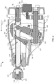
- the motor portion 106 includes a number of ventilation ports 122 which are used to provide cooling air to a motor 124 shown in FIG. 2 .
- An optional noise reduction system (not shown) for reducing noise generated by the motor is positioned within the motor portion 106 to discharge unwanted noise.
- the motor 124 rotatably drives an output shaft 126 which is engaged with a gear 128.
- the gear 128 is fixedly connected to a drive shaft 130 with an offset portion 132.
- the drive shaft 130 rotates about an axis of rotation 136.
- a wobble plate assembly 138 is rotatably positioned on the offset portion 132.
- the wobble plate assembly 138 includes an adaptor arm 140 which drives a plunger assembly 144 in a reciprocating motion.
- a plunger 146 of the plunger assembly 144 is configured to reciprocate along a plunger axis 148.
- a chuck assembly 150 is located at a forward portion of the plunger 146. The chuck assembly 150 releasably holds a saw blade 152.
- the plunger 146 includes an outer wall 160 and an inner wall 162 which defines a chamber 164 at a rearward location of the plunger 146.
- the plunger 146 is supported at a forward location by a front bushing 166 which extends about the outer wall 160.
- a rear bushing 168 which is located partially within the chamber 164.
- the rear bushing 168 includes a stem portion 170 and a head portion 172.
- the stem portion is 170 is supported by at least a portion of the housing 102 and extends into the chamber 164.
- an optional housing for accommodating the motor portion 106 may be provided and disposed within the outer housing 102.
- the stem portion is 170 is supported by the motor housing and extends into the chamber 164.
- the head portion 172 has a radius that is slightly smaller than the radius of the rearward portion of the chamber 164.
- the head portion 172 is spherical.
- the head portion is another curved shape, such as a cylinder. Accordingly, the head portion 172 contacts the inner wall 162 at only a single point of contact whereas in an embodiment with a cylindrical head portion, a line of contact is established.
- the plunger 146 is operably engaged with an upper arm 180 of a pivot arm assembly 182.
- the pivot arm assembly 182 pivots about a pivot 184.
- a pair of lower arms 186 (shown partially in FIG. 3 ) is located generally below the pivot 184.
- the lower arms 186 are pivotably connected to a counterweight 188.
- the counterweight is slidingly supported by a support bar 190.
- the counterweight 188 wraps around the outer wall 160 of the plunger 146 without contacting the plunger 146.
- a user applies power to the motor 124 from the battery pack 118 by selecting a speed range with the dual-speed switch 114 and depressing the variable speed trigger 116. As power is applied to the motor 124, the output shaft 126 rotates.
- Rotation of the shaft 126 forces the gear 128 to rotate and, since the gear 128 is fixedly connected to the drive shaft 130, the drive shaft 130 rotates as well.
- the wobble plate assembly 138 is constrained against movement orthogonal to the plunger axis 148 by the plunger 146. Accordingly, as the drive shaft 130 rotates the top of the wobble plate assembly 138 pivots forwardly, in the direction of the arrow 200 of FIG. 2 . Movement of the top of the wobble plate assembly 138 in the direction of the arrow 200 forces the plunger 146 to move in the direction of the arrow 200.
- the rear bushing 168 and the front bushing 166 maintain the plunger 146 aligned with the plunger axis 148.
- the front bushing 166 encircles the outer wall 160 thereby constraining the plunger 146 from misalignment with the plunger axis 148.
- the rear bushing 168 is an inverse bushing. Thus, the rear bushing 168 contacts the inner wall 162 to constrain the plunger 146 from misalignment with the plunger axis 148.
- the plunger 146 moves forwardly in the direction of the arrow 200, the plunger 146 pushes against the upper arm 180 of the pivot arm assembly 182. This forces the pivot arm assembly 182 to pivot about the pivot 184. As the pivot arm assembly 182 picots, the lower arms 186 are forced rearwardly, in the direction of the arrow 202 of FIG. 3 . The rearward movement of the lower arms 186 force the counterweight 188 to slide rearwardly along the support bar 190.
- the counterweight 188 moves rearwardly in opposition to the forwardly motion of the plunger 146 to a mid-stroke location as depicted in FIGs. 4 and 5 , the counterweight 188 moves directly over the head portion 172 of the rear bushing 168. Because the rear bushing 168 is located within the chamber 164, however, the rear bushing 168 does not interfere with movement of the counterweight 188. Thus, the counterweight 188 need only be spaced apart from the plunger 146 by a distance necessary to clear features of the plunger 146. This allows for a more compact arrangement of components within the nose portion housing 108.
Landscapes
- Engineering & Computer Science (AREA)
- Mechanical Engineering (AREA)
- Sawing (AREA)
Description
- This disclosure relates to power hand tools and more specifically to a reciprocating tool and a method of operating it.
-
US 5 083 376 A discloses a reciprocating tool comprising: a reciprocating plunger, the plunger including an inner wall defining a chamber portion with the plunger; a motor operably connected to the plunger; and a bushing located at least partially within the chamber and contacting the inner wall. A similar reciprocating tool is disclosed inUS2004/049928 A1 which shows a reciprocating tool comprising a reciprocating plunger, the plunger including an inner wall defining a chamber portion within the plunger; a motor operably connected to the plunger; and a bushing located at least partially within the chamber and contacting the inner wall; wherein the bushing includes a head portion, and the head portion contacts the inner wall. - Reciprocating tools that are motor driven, such as saber saws, larger reciprocating saws and the like are usually driven by electric motors that have a rotating output shaft. The rotating motion is translated into reciprocating motion for moving a saw blade or the like in a reciprocating manner. Various approaches have been developed which translate the rotational motion into reciprocating motion. A common approach is the incorporation of a wobble plate drive.
- A "wobble plate" assembly is a configuration wherein a shaft has an angled portion on which an arm is mounted through a ball bearing assembly. The arm is slidingly positioned within a portion of a plunger assembly. As the angled portion of the shaft rotates, the arm translates the rotation of the shaft into a reciprocating movement of the plunger assembly. One example of a reciprocating tool which incorporates a wobble plate drive is
U.S. Patent Publication No. 2011/0247847 , which was published on October 13, 2011. - As the plunger assembly moves along an axis, a significant amount of momentum is created. All of this momentum is absorbed by the tool as the plunger assembly reverses direction. Thus, a user of a reciprocating tool incorporating a wobble plate drive must contend with a powerfully vibrating device. In order to make such reciprocating tools more controllable, reciprocating tools such as the device shown in the
US2001/0247847 patent publication incorporate a counterweight which is driven by a secondary wobble plate in a direction opposite to the direction of the plunger assembly. In order to function properly, the housing enclosing the counterweight must be large enough to allow for travel of the counterweight without touching other components. Thus, while the incorporation of a secondary wobble plate and counterweight is effective, such systems can be bulky and expensive. AlsoEP 0 949 033 A2 discloses a reciprocating tool with a wobble plate assembly comprising an arm axially moving a plunger which is mounted at its outer surface by means of a front and a rear bushing. A counterweight which is driven by a secondary wobble plate is provided, wherein the counterweight in a rear most position is positioned axially spaced to the rear. - A need exists for a reciprocating tool which reduces vibration of a wobble plate drive. A further need exists for a reciprocating tool which reduces vibration of a wobble plate drive which does not rely upon bulky assemblies. A system which reduces vibrations in a reciprocating tool while reducing costs associated with vibration reduction would be further beneficial. A system which reduces the overall size of a reciprocating tool so that it is portable and convenient to use without sacrificing the performance.
- The present invention provides a reciprocating tool according to claim 1 and a method of operating a reciprocating tool according to claim 3.
-
-
FIG. 1 depicts a side perspective view of a reciprocating tool incorporating an inverse bushing in accordance with principles of the disclosure; -
FIG. 2 depicts a side cross-sectional view of the tool ofFIG. 1 with the housing removed and the counterweight positioned about the plunger; -
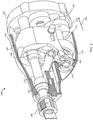
FIG. 3 depicts a side perspective view of the tool ofFIG. 1 with a portion of the housing removed and the counterweight positioned about the plunger; -
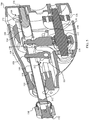
FIG. 4 depicts a side cross-sectional view of the tool ofFIG. 1 with the counterweight at a mid-stroke location; -
FIG. 5 depicts a side perspective view of the tool ofFIG. 1 with the counterweight at a mid-stroke location; and -
FIG. 6 depicts a side cross-sectional view of the tool ofFIG. 1 with the housing removed and the counterweight at its rearward-most location. - For the purposes of promoting an understanding of the principles of the disclosure, reference will now be made to the embodiments illustrated in the drawings and described in the following written specification.
-
FIG. 1 depicts areciprocating saw 100 including anouter housing 102 which includes ahandle portion 104, amotor portion 106, and anose portion 108. Thehandle portion 104 includes agrip 112. A dual-speed switch 114 and avariable speed trigger 116 extend from thehandle portion housing 104. Thehandle portion 104 is configured to removably receive abattery pack 118 which in some embodiments is replaced by a corded power supply. - The
nose portion 108 is shaped to allow a user to grip thetool 100 while thetool 100 is in use and in some embodiments is made from a rubber material. Afoot plate assembly 120 is located forwardly of thenose portion 108. - The
motor portion 106 includes a number ofventilation ports 122 which are used to provide cooling air to amotor 124 shown inFIG. 2 . An optional noise reduction system (not shown) for reducing noise generated by the motor is positioned within themotor portion 106 to discharge unwanted noise. Themotor 124 rotatably drives anoutput shaft 126 which is engaged with agear 128. Thegear 128 is fixedly connected to adrive shaft 130 with anoffset portion 132. Thedrive shaft 130 rotates about an axis ofrotation 136. - A
wobble plate assembly 138 is rotatably positioned on theoffset portion 132. Thewobble plate assembly 138 includes anadaptor arm 140 which drives aplunger assembly 144 in a reciprocating motion. Aplunger 146 of theplunger assembly 144 is configured to reciprocate along aplunger axis 148. Achuck assembly 150 is located at a forward portion of theplunger 146. Thechuck assembly 150 releasably holds asaw blade 152. - The
plunger 146 includes anouter wall 160 and aninner wall 162 which defines achamber 164 at a rearward location of theplunger 146. Theplunger 146 is supported at a forward location by a front bushing 166 which extends about theouter wall 160. At a rearward location, theplunger 146 is supported by arear bushing 168 which is located partially within thechamber 164. - The
rear bushing 168 includes astem portion 170 and ahead portion 172. The stem portion is 170 is supported by at least a portion of thehousing 102 and extends into thechamber 164. In other embodiments, an optional housing for accommodating themotor portion 106 may be provided and disposed within theouter housing 102. In such embodiments, the stem portion is 170 is supported by the motor housing and extends into thechamber 164. Thehead portion 172 has a radius that is slightly smaller than the radius of the rearward portion of thechamber 164. In the embodiment ofFIG. 2 , thehead portion 172 is spherical. In other embodiments, the head portion is another curved shape, such as a cylinder. Accordingly, thehead portion 172 contacts theinner wall 162 at only a single point of contact whereas in an embodiment with a cylindrical head portion, a line of contact is established. - The
plunger 146 is operably engaged with anupper arm 180 of apivot arm assembly 182. Thepivot arm assembly 182 pivots about apivot 184. A pair of lower arms 186 (shown partially inFIG. 3 ) is located generally below thepivot 184. Thelower arms 186 are pivotably connected to acounterweight 188. The counterweight is slidingly supported by asupport bar 190. Thecounterweight 188 wraps around theouter wall 160 of theplunger 146 without contacting theplunger 146. - In operation, a user applies power to the
motor 124 from thebattery pack 118 by selecting a speed range with the dual-speed switch 114 and depressing thevariable speed trigger 116. As power is applied to themotor 124, theoutput shaft 126 rotates. - Rotation of the
shaft 126 forces thegear 128 to rotate and, since thegear 128 is fixedly connected to thedrive shaft 130, thedrive shaft 130 rotates as well. Thewobble plate assembly 138 is constrained against movement orthogonal to theplunger axis 148 by theplunger 146. Accordingly, as thedrive shaft 130 rotates the top of thewobble plate assembly 138 pivots forwardly, in the direction of thearrow 200 ofFIG. 2 . Movement of the top of thewobble plate assembly 138 in the direction of thearrow 200 forces theplunger 146 to move in the direction of thearrow 200. - As the
plunger 146 moves forwardly, therear bushing 168 and thefront bushing 166 maintain theplunger 146 aligned with theplunger axis 148. Thefront bushing 166 encircles theouter wall 160 thereby constraining theplunger 146 from misalignment with theplunger axis 148. Therear bushing 168 is an inverse bushing. Thus, therear bushing 168 contacts theinner wall 162 to constrain theplunger 146 from misalignment with theplunger axis 148. - As the
plunger 146 moves forwardly in the direction of thearrow 200, theplunger 146 pushes against theupper arm 180 of thepivot arm assembly 182. This forces thepivot arm assembly 182 to pivot about thepivot 184. As thepivot arm assembly 182 picots, thelower arms 186 are forced rearwardly, in the direction of thearrow 202 ofFIG. 3 . The rearward movement of thelower arms 186 force thecounterweight 188 to slide rearwardly along thesupport bar 190. - As the
counterweight 188 moves rearwardly in opposition to the forwardly motion of theplunger 146 to a mid-stroke location as depicted inFIGs. 4 and5 , thecounterweight 188 moves directly over thehead portion 172 of therear bushing 168. Because therear bushing 168 is located within thechamber 164, however, therear bushing 168 does not interfere with movement of thecounterweight 188. Thus, thecounterweight 188 need only be spaced apart from theplunger 146 by a distance necessary to clear features of theplunger 146. This allows for a more compact arrangement of components within thenose portion housing 108. - Continued rotation of the
drive shaft 130 results in further forward movement of theplunger 146 to the location shown inFIG. 6 . With theplunger 146 at its forward-most location, thecounterweight 188 is forced to its rearward-most location. In the embodiment ofFIG. 6 , thecounterweight 188 wraps around theentire head portion 172 when thecounterweight 188 is at its rearward-most location. - As the
motor 124 continues to rotate, the above described movement of thewobble plate assembly 138 is reversed, causing the movement of thecounterweight 188 and theplunger 146 to be reversed. Theplunger 146 thus reciprocates along theplunger axis 148 out of phase with the reciprocation of thecounterweight 188 along theplunger axis 148. - While the invention has been illustrated and described in detail in the drawings and foregoing description, the same should be considered as illustrative and not restrictive in character. However, the invention may also include any changes or modifications that fall within the scope of the claims.
Claims (3)
- A reciprocating tool (100) comprising:a reciprocating plunger (146), the plunger (146) including an inner wall (162) defining a chamber portion (164) within the plunger (146);a motor (124) operably connected to the plunger (146); andan inverse bushing (168) including a stem portion (170) and a spherically shaped head portion (172), wherein the head portion (172) is located at least partially within the chamber and contacts the inner wall (162),a reciprocating counterweight (188) wrapping at least partially about an outer wall (160) of the plunger (146)a pivot arm assembly (182) operably connected to the plunger (146) and to the counterweight (188) such that as the plunger (146) moves forwardly, the counterweight (188) moves rearwardly,wherein the counterweight (188) is movable between a forward-most location and a rearward-most location; andwherein when the counterweight (188) is at the rearward-most location, the head portion (172) is at least partially surrounded by the counterweight (188).
- The reciprocating tool (100) of claim 1, wherein:
the head portion (164) is cylindrically shaped. - A method of operating a reciprocating tool (100), comprising:rotating a shaft (126) with a motor (124);translating the rotation of the shaft (126) into a reciprocating motion of a plunger (146);supporting the reciprocating plunger (146) with an inverse bushing (168) including a stem portion (170) and spherically shaped head portion (172), wherein the head portion (172) contacts an inner wall (162) of the plunger (146) and is located at least partially within a chamber (164) defined by the inner wall (162) of the plunger (146); andreciprocating a counterweight (188) wrapped at least partially about an outer wall (160) of the plunger (146) in opposition to the reciprocation of the plunger (146) using a pivot arm assembly (182) operably connected to the plunger (146) and to the counterweight (188) such that as the plunger (146) moves forwardly, the counterweight (188) moves rearwardly, wherein the counterweight (188) is movable between a forward-most location and a rearward-most location, wherein in the rearward-most location the head portion (172) of the bushing (168) is at least partially surrounded by the counterweight (188).
Applications Claiming Priority (2)
| Application Number | Priority Date | Filing Date | Title |
|---|---|---|---|
| US201261746252P | 2012-12-27 | 2012-12-27 | |
| PCT/US2013/077662 WO2014105884A1 (en) | 2012-12-27 | 2013-12-24 | Reciprocating tool with internal guiding bushing |
Publications (2)
| Publication Number | Publication Date |
|---|---|
| EP2938452A1 EP2938452A1 (en) | 2015-11-04 |
| EP2938452B1 true EP2938452B1 (en) | 2019-06-12 |
Family
ID=49958729
Family Applications (1)
| Application Number | Title | Priority Date | Filing Date |
|---|---|---|---|
| EP13821612.2A Active EP2938452B1 (en) | 2012-12-27 | 2013-12-24 | Reciprocating tool with internal guiding bushing and method of operating such a tool |
Country Status (4)
| Country | Link |
|---|---|
| US (1) | US10207347B2 (en) |
| EP (1) | EP2938452B1 (en) |
| CN (1) | CN105377489B (en) |
| WO (1) | WO2014105884A1 (en) |
Families Citing this family (4)
| Publication number | Priority date | Publication date | Assignee | Title |
|---|---|---|---|---|
| JP7287981B2 (en) * | 2018-05-29 | 2023-06-06 | ローベル バーンバウマシーネン ゲゼルシャフト ミット ベシュレンクテル ハフツング | Impact wrench for tightening and loosening track nuts and screws |
| US11033973B2 (en) * | 2018-06-12 | 2021-06-15 | Milwaukee Electric Tool Corporation | Spindle for a reciprocating saw |
| CN109758348B (en) * | 2019-01-15 | 2021-06-25 | 温州职业技术学院 | Fascia gun and its installation process |
| CN216370464U (en) * | 2019-01-16 | 2022-04-26 | 米沃奇电动工具公司 | Reciprocating saw |
Citations (4)
| Publication number | Priority date | Publication date | Assignee | Title |
|---|---|---|---|---|
| US1342131A (en) * | 1919-04-15 | 1920-06-01 | Mycock William | Bearing for the cylinders of drying-machines |
| US5689891A (en) * | 1994-12-13 | 1997-11-25 | Milwaukee Electric Tool Corp. | Clutch mechanism for reciprocating saws |
| EP0949033A2 (en) * | 1998-04-09 | 1999-10-13 | Black & Decker Inc. | Reciprocating saw with pivoted arm drive |
| US20040049928A1 (en) * | 2001-12-18 | 2004-03-18 | Phillips Alan Gene | Bearing for a reciprocating shaft of a reciprocating saw |
Family Cites Families (22)
| Publication number | Priority date | Publication date | Assignee | Title |
|---|---|---|---|---|
| US2547922A (en) * | 1948-01-30 | 1951-04-10 | Joseph L Bechtold | Portable motor operated hand scroll saw |
| US3130759A (en) * | 1960-12-01 | 1964-04-28 | Sunbeam Corp | Tool attachment for portable power unit |
| US3365963A (en) * | 1965-07-19 | 1968-01-30 | Singer Co | Battery powered scissors |
| US4436163A (en) * | 1978-12-13 | 1984-03-13 | Black & Decker Inc. | Arrangement for converting rotary motion to reciprocatory motion |
| US5083376A (en) | 1988-11-14 | 1992-01-28 | Black & Decker Inc. | Thrust bearing arrangement for a power tool transmission |
| US5099705A (en) * | 1989-12-05 | 1992-03-31 | Konstantins Dravnieks | Hand-held reciprocating working tool |
| US5079844A (en) * | 1990-11-13 | 1992-01-14 | Milwaukee Electric Tool Corporation | Counterbalanced reciprocating mechanism |
| US5212887A (en) * | 1992-03-18 | 1993-05-25 | S-B Power Tool Company | Counterbalanced orbital drive mechanism for saws and the like |
| US5450925A (en) * | 1994-04-05 | 1995-09-19 | S-B Power Tool Company | Lubrication system for a reciprocating power tool |
| SE510893C2 (en) * | 1995-10-18 | 1999-07-05 | Dentatus Ab | Hand apparatus for operating a sideways machining tool |
| US6829831B1 (en) * | 1996-08-19 | 2004-12-14 | Milwaukee Electric Tool Corporation | Reciprocating saw with rocker motion |
| US7127973B2 (en) * | 1998-02-09 | 2006-10-31 | Milwaukee Electric Tool Corporation | Reciprocating saw |
| US6249979B1 (en) * | 1998-08-13 | 2001-06-26 | Milwaukee Electric Tool Corporation | Orbital reciprocating saw |
| US6634107B2 (en) * | 1999-03-12 | 2003-10-21 | Hitachi Koki Co., Ltd. | Cutting mechanism for a saber saw |
| JP3663970B2 (en) | 1999-04-16 | 2005-06-22 | 日立工機株式会社 | Saver saw |
| SE517746C2 (en) * | 2000-10-20 | 2002-07-09 | Ericsson Telefon Ab L M | Bearing device, Cavity filter and method of mounting thereof |
| EP1277535B1 (en) * | 2001-04-10 | 2007-03-07 | Milwaukee Electric Tool Corporation | Reciprocating saw |
| US7707729B2 (en) | 2007-02-02 | 2010-05-04 | Robert Bosch Gmbh | Drive mechanism for a reciprocating tool |
| US8307910B2 (en) * | 2010-04-07 | 2012-11-13 | Robert Bosch Gmbh | Drive mechanism for a reciprocating tool |
| US20120073849A1 (en) * | 2010-09-28 | 2012-03-29 | Hayco Manufacturing Limited | Variable amplitude vibratory appliance |
| DE102011007725A1 (en) | 2011-04-20 | 2012-10-25 | Hilti Aktiengesellschaft | Hand tool and absorber |
| DE102011079828A1 (en) * | 2011-07-26 | 2013-01-31 | Hilti Aktiengesellschaft | Hand tool with three-point bearing |
-
2013
- 2013-12-17 US US14/109,153 patent/US10207347B2/en active Active
- 2013-12-24 CN CN201380073864.XA patent/CN105377489B/en active Active
- 2013-12-24 EP EP13821612.2A patent/EP2938452B1/en active Active
- 2013-12-24 WO PCT/US2013/077662 patent/WO2014105884A1/en not_active Ceased
Patent Citations (4)
| Publication number | Priority date | Publication date | Assignee | Title |
|---|---|---|---|---|
| US1342131A (en) * | 1919-04-15 | 1920-06-01 | Mycock William | Bearing for the cylinders of drying-machines |
| US5689891A (en) * | 1994-12-13 | 1997-11-25 | Milwaukee Electric Tool Corp. | Clutch mechanism for reciprocating saws |
| EP0949033A2 (en) * | 1998-04-09 | 1999-10-13 | Black & Decker Inc. | Reciprocating saw with pivoted arm drive |
| US20040049928A1 (en) * | 2001-12-18 | 2004-03-18 | Phillips Alan Gene | Bearing for a reciprocating shaft of a reciprocating saw |
Also Published As
| Publication number | Publication date |
|---|---|
| US20140182428A1 (en) | 2014-07-03 |
| WO2014105884A1 (en) | 2014-07-03 |
| CN105377489B (en) | 2018-03-30 |
| US10207347B2 (en) | 2019-02-19 |
| CN105377489A (en) | 2016-03-02 |
| EP2938452A1 (en) | 2015-11-04 |
Similar Documents
| Publication | Publication Date | Title |
|---|---|---|
| US8403076B2 (en) | Power tool | |
| EP3568253B1 (en) | Reciprocating saw | |
| EP1188505B1 (en) | Reciprocating cutting tools | |
| US10300541B2 (en) | Reciprocating saw | |
| EP2694260B1 (en) | Jigsaw | |
| JP2017205864A (en) | Hydrodynamic compression or cutting tool | |
| US10207347B2 (en) | Reciprocating tool with inverse bushing | |
| US11607738B2 (en) | Reciprocating saw | |
| US10272506B2 (en) | Reciprocating tool with linear guides | |
| EP2938465B1 (en) | Reciprocating tool with fluid driven counterweight | |
| EP2969341B1 (en) | Reciprocating tool with biasing assembly | |
| JP6711363B2 (en) | Reciprocating tool | |
| CN114378364A (en) | Reciprocating saw | |
| JP5019101B2 (en) | Electric tool | |
| US20170282264A1 (en) | Hand-Held Cutting Tool | |
| JP5997038B2 (en) | Handheld power tool | |
| WO2014159674A1 (en) | Oscillating tool | |
| JP2022086467A (en) | Work machine |
Legal Events
| Date | Code | Title | Description |
|---|---|---|---|
| PUAI | Public reference made under article 153(3) epc to a published international application that has entered the european phase |
Free format text: ORIGINAL CODE: 0009012 |
|
| 17P | Request for examination filed |
Effective date: 20150727 |
|
| AK | Designated contracting states |
Kind code of ref document: A1 Designated state(s): AL AT BE BG CH CY CZ DE DK EE ES FI FR GB GR HR HU IE IS IT LI LT LU LV MC MK MT NL NO PL PT RO RS SE SI SK SM TR |
|
| AX | Request for extension of the european patent |
Extension state: BA ME |
|
| RAP1 | Party data changed (applicant data changed or rights of an application transferred) |
Owner name: ROBERT BOSCH GMBH |
|
| DAX | Request for extension of the european patent (deleted) | ||
| STAA | Information on the status of an ep patent application or granted ep patent |
Free format text: STATUS: EXAMINATION IS IN PROGRESS |
|
| 17Q | First examination report despatched |
Effective date: 20180507 |
|
| GRAP | Despatch of communication of intention to grant a patent |
Free format text: ORIGINAL CODE: EPIDOSNIGR1 |
|
| STAA | Information on the status of an ep patent application or granted ep patent |
Free format text: STATUS: GRANT OF PATENT IS INTENDED |
|
| INTG | Intention to grant announced |
Effective date: 20181220 |
|
| GRAS | Grant fee paid |
Free format text: ORIGINAL CODE: EPIDOSNIGR3 |
|
| GRAA | (expected) grant |
Free format text: ORIGINAL CODE: 0009210 |
|
| STAA | Information on the status of an ep patent application or granted ep patent |
Free format text: STATUS: THE PATENT HAS BEEN GRANTED |
|
| AK | Designated contracting states |
Kind code of ref document: B1 Designated state(s): AL AT BE BG CH CY CZ DE DK EE ES FI FR GB GR HR HU IE IS IT LI LT LU LV MC MK MT NL NO PL PT RO RS SE SI SK SM TR |
|
| REG | Reference to a national code |
Ref country code: GB Ref legal event code: FG4D |
|
| REG | Reference to a national code |
Ref country code: CH Ref legal event code: EP |
|
| REG | Reference to a national code |
Ref country code: AT Ref legal event code: REF Ref document number: 1141948 Country of ref document: AT Kind code of ref document: T Effective date: 20190615 |
|
| REG | Reference to a national code |
Ref country code: DE Ref legal event code: R096 Ref document number: 602013056610 Country of ref document: DE |
|
| REG | Reference to a national code |
Ref country code: IE Ref legal event code: FG4D |
|
| REG | Reference to a national code |
Ref country code: NL Ref legal event code: MP Effective date: 20190612 |
|
| REG | Reference to a national code |
Ref country code: LT Ref legal event code: MG4D |
|
| PG25 | Lapsed in a contracting state [announced via postgrant information from national office to epo] |
Ref country code: AL Free format text: LAPSE BECAUSE OF FAILURE TO SUBMIT A TRANSLATION OF THE DESCRIPTION OR TO PAY THE FEE WITHIN THE PRESCRIBED TIME-LIMIT Effective date: 20190612 Ref country code: NO Free format text: LAPSE BECAUSE OF FAILURE TO SUBMIT A TRANSLATION OF THE DESCRIPTION OR TO PAY THE FEE WITHIN THE PRESCRIBED TIME-LIMIT Effective date: 20190912 Ref country code: FI Free format text: LAPSE BECAUSE OF FAILURE TO SUBMIT A TRANSLATION OF THE DESCRIPTION OR TO PAY THE FEE WITHIN THE PRESCRIBED TIME-LIMIT Effective date: 20190612 Ref country code: LT Free format text: LAPSE BECAUSE OF FAILURE TO SUBMIT A TRANSLATION OF THE DESCRIPTION OR TO PAY THE FEE WITHIN THE PRESCRIBED TIME-LIMIT Effective date: 20190612 Ref country code: SE Free format text: LAPSE BECAUSE OF FAILURE TO SUBMIT A TRANSLATION OF THE DESCRIPTION OR TO PAY THE FEE WITHIN THE PRESCRIBED TIME-LIMIT Effective date: 20190612 Ref country code: HR Free format text: LAPSE BECAUSE OF FAILURE TO SUBMIT A TRANSLATION OF THE DESCRIPTION OR TO PAY THE FEE WITHIN THE PRESCRIBED TIME-LIMIT Effective date: 20190612 |
|
| PG25 | Lapsed in a contracting state [announced via postgrant information from national office to epo] |
Ref country code: LV Free format text: LAPSE BECAUSE OF FAILURE TO SUBMIT A TRANSLATION OF THE DESCRIPTION OR TO PAY THE FEE WITHIN THE PRESCRIBED TIME-LIMIT Effective date: 20190612 Ref country code: GR Free format text: LAPSE BECAUSE OF FAILURE TO SUBMIT A TRANSLATION OF THE DESCRIPTION OR TO PAY THE FEE WITHIN THE PRESCRIBED TIME-LIMIT Effective date: 20190913 Ref country code: BG Free format text: LAPSE BECAUSE OF FAILURE TO SUBMIT A TRANSLATION OF THE DESCRIPTION OR TO PAY THE FEE WITHIN THE PRESCRIBED TIME-LIMIT Effective date: 20190912 Ref country code: RS Free format text: LAPSE BECAUSE OF FAILURE TO SUBMIT A TRANSLATION OF THE DESCRIPTION OR TO PAY THE FEE WITHIN THE PRESCRIBED TIME-LIMIT Effective date: 20190612 |
|
| REG | Reference to a national code |
Ref country code: AT Ref legal event code: MK05 Ref document number: 1141948 Country of ref document: AT Kind code of ref document: T Effective date: 20190612 |
|
| PG25 | Lapsed in a contracting state [announced via postgrant information from national office to epo] |
Ref country code: PT Free format text: LAPSE BECAUSE OF FAILURE TO SUBMIT A TRANSLATION OF THE DESCRIPTION OR TO PAY THE FEE WITHIN THE PRESCRIBED TIME-LIMIT Effective date: 20191014 Ref country code: AT Free format text: LAPSE BECAUSE OF FAILURE TO SUBMIT A TRANSLATION OF THE DESCRIPTION OR TO PAY THE FEE WITHIN THE PRESCRIBED TIME-LIMIT Effective date: 20190612 Ref country code: NL Free format text: LAPSE BECAUSE OF FAILURE TO SUBMIT A TRANSLATION OF THE DESCRIPTION OR TO PAY THE FEE WITHIN THE PRESCRIBED TIME-LIMIT Effective date: 20190612 Ref country code: CZ Free format text: LAPSE BECAUSE OF FAILURE TO SUBMIT A TRANSLATION OF THE DESCRIPTION OR TO PAY THE FEE WITHIN THE PRESCRIBED TIME-LIMIT Effective date: 20190612 Ref country code: RO Free format text: LAPSE BECAUSE OF FAILURE TO SUBMIT A TRANSLATION OF THE DESCRIPTION OR TO PAY THE FEE WITHIN THE PRESCRIBED TIME-LIMIT Effective date: 20190612 Ref country code: EE Free format text: LAPSE BECAUSE OF FAILURE TO SUBMIT A TRANSLATION OF THE DESCRIPTION OR TO PAY THE FEE WITHIN THE PRESCRIBED TIME-LIMIT Effective date: 20190612 Ref country code: SK Free format text: LAPSE BECAUSE OF FAILURE TO SUBMIT A TRANSLATION OF THE DESCRIPTION OR TO PAY THE FEE WITHIN THE PRESCRIBED TIME-LIMIT Effective date: 20190612 |
|
| PG25 | Lapsed in a contracting state [announced via postgrant information from national office to epo] |
Ref country code: ES Free format text: LAPSE BECAUSE OF FAILURE TO SUBMIT A TRANSLATION OF THE DESCRIPTION OR TO PAY THE FEE WITHIN THE PRESCRIBED TIME-LIMIT Effective date: 20190612 Ref country code: IT Free format text: LAPSE BECAUSE OF FAILURE TO SUBMIT A TRANSLATION OF THE DESCRIPTION OR TO PAY THE FEE WITHIN THE PRESCRIBED TIME-LIMIT Effective date: 20190612 Ref country code: IS Free format text: LAPSE BECAUSE OF FAILURE TO SUBMIT A TRANSLATION OF THE DESCRIPTION OR TO PAY THE FEE WITHIN THE PRESCRIBED TIME-LIMIT Effective date: 20191012 Ref country code: SM Free format text: LAPSE BECAUSE OF FAILURE TO SUBMIT A TRANSLATION OF THE DESCRIPTION OR TO PAY THE FEE WITHIN THE PRESCRIBED TIME-LIMIT Effective date: 20190612 |
|
| REG | Reference to a national code |
Ref country code: DE Ref legal event code: R097 Ref document number: 602013056610 Country of ref document: DE |
|
| PG25 | Lapsed in a contracting state [announced via postgrant information from national office to epo] |
Ref country code: TR Free format text: LAPSE BECAUSE OF FAILURE TO SUBMIT A TRANSLATION OF THE DESCRIPTION OR TO PAY THE FEE WITHIN THE PRESCRIBED TIME-LIMIT Effective date: 20190612 |
|
| PLBE | No opposition filed within time limit |
Free format text: ORIGINAL CODE: 0009261 |
|
| STAA | Information on the status of an ep patent application or granted ep patent |
Free format text: STATUS: NO OPPOSITION FILED WITHIN TIME LIMIT |
|
| RAP2 | Party data changed (patent owner data changed or rights of a patent transferred) |
Owner name: ROBERT BOSCH GMBH |
|
| PG25 | Lapsed in a contracting state [announced via postgrant information from national office to epo] |
Ref country code: DK Free format text: LAPSE BECAUSE OF FAILURE TO SUBMIT A TRANSLATION OF THE DESCRIPTION OR TO PAY THE FEE WITHIN THE PRESCRIBED TIME-LIMIT Effective date: 20190612 Ref country code: PL Free format text: LAPSE BECAUSE OF FAILURE TO SUBMIT A TRANSLATION OF THE DESCRIPTION OR TO PAY THE FEE WITHIN THE PRESCRIBED TIME-LIMIT Effective date: 20190612 |
|
| 26N | No opposition filed |
Effective date: 20200313 |
|
| PG25 | Lapsed in a contracting state [announced via postgrant information from national office to epo] |
Ref country code: SI Free format text: LAPSE BECAUSE OF FAILURE TO SUBMIT A TRANSLATION OF THE DESCRIPTION OR TO PAY THE FEE WITHIN THE PRESCRIBED TIME-LIMIT Effective date: 20190612 Ref country code: IS Free format text: LAPSE BECAUSE OF FAILURE TO SUBMIT A TRANSLATION OF THE DESCRIPTION OR TO PAY THE FEE WITHIN THE PRESCRIBED TIME-LIMIT Effective date: 20200224 |
|
| PG2D | Information on lapse in contracting state deleted |
Ref country code: IS |
|
| REG | Reference to a national code |
Ref country code: CH Ref legal event code: PL |
|
| REG | Reference to a national code |
Ref country code: BE Ref legal event code: MM Effective date: 20191231 |
|
| PG25 | Lapsed in a contracting state [announced via postgrant information from national office to epo] |
Ref country code: MC Free format text: LAPSE BECAUSE OF FAILURE TO SUBMIT A TRANSLATION OF THE DESCRIPTION OR TO PAY THE FEE WITHIN THE PRESCRIBED TIME-LIMIT Effective date: 20190612 |
|
| GBPC | Gb: european patent ceased through non-payment of renewal fee |
Effective date: 20191224 |
|
| PG25 | Lapsed in a contracting state [announced via postgrant information from national office to epo] |
Ref country code: FR Free format text: LAPSE BECAUSE OF NON-PAYMENT OF DUE FEES Effective date: 20191231 Ref country code: LU Free format text: LAPSE BECAUSE OF NON-PAYMENT OF DUE FEES Effective date: 20191224 Ref country code: GB Free format text: LAPSE BECAUSE OF NON-PAYMENT OF DUE FEES Effective date: 20191224 Ref country code: IE Free format text: LAPSE BECAUSE OF NON-PAYMENT OF DUE FEES Effective date: 20191224 |
|
| PG25 | Lapsed in a contracting state [announced via postgrant information from national office to epo] |
Ref country code: BE Free format text: LAPSE BECAUSE OF NON-PAYMENT OF DUE FEES Effective date: 20191231 Ref country code: LI Free format text: LAPSE BECAUSE OF NON-PAYMENT OF DUE FEES Effective date: 20191231 Ref country code: CH Free format text: LAPSE BECAUSE OF NON-PAYMENT OF DUE FEES Effective date: 20191231 |
|
| PG25 | Lapsed in a contracting state [announced via postgrant information from national office to epo] |
Ref country code: CY Free format text: LAPSE BECAUSE OF FAILURE TO SUBMIT A TRANSLATION OF THE DESCRIPTION OR TO PAY THE FEE WITHIN THE PRESCRIBED TIME-LIMIT Effective date: 20190612 |
|
| PG25 | Lapsed in a contracting state [announced via postgrant information from national office to epo] |
Ref country code: HU Free format text: LAPSE BECAUSE OF FAILURE TO SUBMIT A TRANSLATION OF THE DESCRIPTION OR TO PAY THE FEE WITHIN THE PRESCRIBED TIME-LIMIT; INVALID AB INITIO Effective date: 20131224 Ref country code: MT Free format text: LAPSE BECAUSE OF FAILURE TO SUBMIT A TRANSLATION OF THE DESCRIPTION OR TO PAY THE FEE WITHIN THE PRESCRIBED TIME-LIMIT Effective date: 20190612 |
|
| PG25 | Lapsed in a contracting state [announced via postgrant information from national office to epo] |
Ref country code: MK Free format text: LAPSE BECAUSE OF FAILURE TO SUBMIT A TRANSLATION OF THE DESCRIPTION OR TO PAY THE FEE WITHIN THE PRESCRIBED TIME-LIMIT Effective date: 20190612 |
|
| REG | Reference to a national code |
Ref country code: DE Ref legal event code: R084 Ref document number: 602013056610 Country of ref document: DE |
|
| PGFP | Annual fee paid to national office [announced via postgrant information from national office to epo] |
Ref country code: DE Payment date: 20260223 Year of fee payment: 13 |