EP2938143A1 - Control device and communication system - Google Patents
Control device and communication system Download PDFInfo
- Publication number
- EP2938143A1 EP2938143A1 EP15164331.9A EP15164331A EP2938143A1 EP 2938143 A1 EP2938143 A1 EP 2938143A1 EP 15164331 A EP15164331 A EP 15164331A EP 2938143 A1 EP2938143 A1 EP 2938143A1
- Authority
- EP
- European Patent Office
- Prior art keywords
- control device
- channel
- wireless communication
- slave
- communication
- Prior art date
- Legal status (The legal status is an assumption and is not a legal conclusion. Google has not performed a legal analysis and makes no representation as to the accuracy of the status listed.)
- Granted
Links
Images







Classifications
-
- H—ELECTRICITY
- H04—ELECTRIC COMMUNICATION TECHNIQUE
- H04W—WIRELESS COMMUNICATION NETWORKS
- H04W74/00—Wireless channel access
- H04W74/08—Non-scheduled access, e.g. ALOHA
- H04W74/0833—Random access procedures, e.g. with 4-step access
- H04W74/0841—Random access procedures, e.g. with 4-step access with collision treatment
- H04W74/085—Random access procedures, e.g. with 4-step access with collision treatment collision avoidance
-
- H—ELECTRICITY
- H04—ELECTRIC COMMUNICATION TECHNIQUE
- H04W—WIRELESS COMMUNICATION NETWORKS
- H04W56/00—Synchronisation arrangements
- H04W56/001—Synchronization between nodes
- H04W56/0015—Synchronization between nodes one node acting as a reference for the others
-
- H—ELECTRICITY
- H04—ELECTRIC COMMUNICATION TECHNIQUE
- H04W—WIRELESS COMMUNICATION NETWORKS
- H04W74/00—Wireless channel access
- H04W74/04—Scheduled access
-
- H—ELECTRICITY
- H04—ELECTRIC COMMUNICATION TECHNIQUE
- H04W—WIRELESS COMMUNICATION NETWORKS
- H04W84/00—Network topologies
- H04W84/02—Hierarchically pre-organised networks, e.g. paging networks, cellular networks, WLAN [Wireless Local Area Network] or WLL [Wireless Local Loop]
- H04W84/10—Small scale networks; Flat hierarchical networks
- H04W84/12—WLAN [Wireless Local Area Networks]
-
- H—ELECTRICITY
- H04—ELECTRIC COMMUNICATION TECHNIQUE
- H04W—WIRELESS COMMUNICATION NETWORKS
- H04W84/00—Network topologies
- H04W84/18—Self-organising networks, e.g. ad-hoc networks or sensor networks
- H04W84/20—Leader-follower arrangements
Definitions
- the present invention relates to a control device and a communication system.
- a client device having a power source control device is connected to a LAN (Local Area Network) together with a host computer (for example, see Japanese Laid-open Patent Publication No. 6-112960 ).
- a technology in which one of servers that are connected to an uninterruptible power source via communication cables is determined as a master server, the others are determined as slave servers, and a shut-down instruction is sent to the slave servers when the master server detects a power source abnormity of the uninterruptible power source (for example, see Japanese Laid-open Patent Publication No. 2005-78174 ).
- a communication system 1 that has a client terminal 2, control devices 4A to 4E, wireless base devices 5A to 5E, and power source control devices 6A to 6E, as illustrated in FIG 1 .
- the client terminal 2 is connected to the control devices 4A to 4E via a wired network 3.
- the control devices 4A to 4E are respectively connected to the wireless base devices 5A to 5E.
- the wireless base devices 5A to 5E are respectively connected to the power source control devices 6A to 6E via wireless communication.
- the wireless base devices 5A to 5E respectively communicate with the power source control devices 6A to 6E with respect to electrical power information without wires.
- the electrical power information acquired by the power source control devices 6A to 6E are respectively stored in the control devices 4A to 4E via the wireless base devices 5A to 5E.
- the user can browse the electrical power information acquired by the power source control devices 6A to 6E by accessing the control devices 4A to 4E via the client terminal 2.
- the user wants to browse the electrical power information acquired by a specific power source control device, the user has to understand control devices that are connected to the specific power source control device. That is, there is a problem that the user has to understand connection relationships between the power source control devices and the control devices and thereby the user has heavy workload.
- control device and a communication system that are capable of suppressing an interfere of a wireless communication without putting a load to a user.
- a control device that performs wireless communication and is connected to another control device via a wired network including: an acquirer that acquires information relating to a channel and a communication timing used for wireless communication via the wired network from another control device that is made to act as a slave; a generator that generates a setting of a channel and a communication timing in which wireless communication performed by the another control device is free of interference, based on information relating to a channel and a communication timing used for wireless communication of the control device and information relating to the channel and the communication timing used for the wireless communication that are acquired by the acquirer; and a reporter that reports the setting of the channel and the timing generated by the generator to the another control device that is made to act as the slave via the wired network.
- a communication system including: a plurality of control devices that are connected to each other via a wired network; a plurality of opposing control devices that respectively perform wireless communication with the plurality of control devices; and an information processing device that is connected to the plurality of control devices via the wired network, and includes a setter that makes one of the plurality of control devices act as a master and makes the other control devices act as a slave, wherein: the master includes: an acquirer that acquires information relating to a channel and a communication timing used for a wireless communication via the wired network from the slave; a generator that generates a setting of a channel and a communication timing that is free of interference in the wireless communication between the plurality of control devices and the plurality of opposing control devices, based on information relating to a channel and a communication timing used for a wireless communication that the master uses and information relating to the channel and the communication timing used for the wireless communication that are acquired by the acquirer; and a reporter that
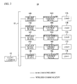
- FIG 2 illustrates a structure diagram of a communication system in accordance with an embodiment.
- a communication system 11 has a client terminal 12 and control devices 14A to 14E.
- the client terminal 12 is connected to the control devices 14A to 14E via a wired network 13 (for example, a LAN).
- the control devices 14A to 14E have a function as a wireless base device for respectively communicating with power source control devices 16A to 16E with wireless communication.
- the control devices 14A to 14E are respectively connected to the power source control devices 16A to 16E via wireless communication.
- the control devices 14A to 14E respectively acquire electrical power information from the power source control devices 16A to 16E acting as opposing control devices.
- the electrical power information is an example of possession information which the power source control devices 16A to 16E possess.
- the power source control devices 16A to 16E are respectively connected to loads 17A to 17E.
- the loads 17A to 17E are electrical appliances and are computers, mobile phones, refrigerators, televisions or the like.
- FIG 3 illustrates a block diagram of the client terminal 12.
- the client terminal 12 is an information processing device and is a computer or the like.
- the client terminal 12 has a CPU 121 that controls a whole thereof, a memory 122 and a hard disk drive 123 that store a predetermined program or data, a display device 124 that shows a program or data, an input device 125 such as a key board or a mouse that inputs data, and a local area network interface (LAN IF) 126.
- LAN IF local area network interface
- the hard disk drive 123 stores a setting program that makes one of the control devices 14A to 14E act as a master and makes the others act as slaves.
- the CPU 121 reads the setting program, writes the setting program in the memory 122, and executes the setting program.
- the CPU 121 makes one of the control devices 14A to 14E act as a master and makes the others act as slaves in accordance with an instruction from the input device 125.
- the setting of the master and the slaves can be changed through the input device 125.
- the control device 14A is made to act as a master, and the control devices 14B to 14E are made to act as slaves.
- the LAN IF 126 is connected to the wired network 13 via a LAN cable.
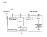
- FIG 4 illustrates a block diagram of a structure of the control device 14A.
- the control devices 14B to 14E have the same structure as the control device 14A.
- FIG 5 illustrates a block diagram of a structure of the power source control device 16A.
- the power source control devices 16B to 16E have the same structure as the power source control device 16A.
- the control device 14A of FIG 4 has a local area network interface (LAN IF) 141, a PHY (Physical Layer Chip) module 142, a CPU 143, a memory 144, a built-in clock (real time clock; RTC) 145, a frequency convertor 146 and an antenna 147.
- LAN IF local area network interface
- PHY Physical Layer Chip
- RTC real time clock
- the LAN IF 141 and the CPU 143 of the control device 14A acting as a master acts as an acquirer, a reporter and a sender.
- the CPU 143 of the master acts as a generator, for example.
- the frequency convertor 146, the antenna 147 and the CPU 143 of the master act as a second acquirer, for example.
- the memory 144 of the master acts as a holder, for example.
- Each CPU 143 of the control devices 14B to 14E acting as slaves acts as a changer, for example.
- the frequency convertor 146, the antenna 147 and the CPU 143 of the slaves act as a third acquirer, for example.
- the LAN IF 141 and the CPU 143 of the slaves act as a second sender, for example.
- the power source control device 16A of FIG. 5 has an antenna 161, a frequency convertor 162, a CPU 163, a memory 164, an electrical power measure 165, a plug 166 and an electrical power acquirer 167.
- the LAN IF 141 is connected to the wired network 13 via a LAN cable.
- the PHY module 142 performs a conversion between data and an electrical signal.
- the CPU 143 controls an entire operation of the control device.
- the memory 144 stores data, information and so on.
- the RTC 145 measures a time. The times of the control devices 14A to 14E are consistent with each other.
- the frequency convertor 146 changes a frequency band used for the communication with the power source control device 16A.
- the antenna 147 is used for sending information to the power source control device 16A or receiving information from the power source control device 16A.
- the antenna 161 is used for sending information to the control device 14A or receiving information from the control device 14A.
- the frequency convertor 162 changes a frequency band used for the communication with the control device 14A.
- the CPU 163 controls an entire operation of the power source control device.
- the memory 164 stores data, information and so on.
- the electrical power measure 165 measures electrical power information of a load (load 17A) such as a consumption power, a consumption current or a voltage.
- the plug 166 supplies an electrical power to the connected load via the electrical power acquirer 167.
- the electrical power acquirer 167 is connected to an outer power source and acquires the electrical power supplied to the load from the outer power source.
- the control device 14A and the power source control device 16A communicate with each other through wireless communication with use of the antennas 147 and 161 and the frequency convertors 146 and 162.
- the power source control device 16A supplies electrical power to the load connected to the plug 166 via the electrical power acquirer 167 and measures electrical power information of the load such as the consumption power, the consumption current or the voltage.
- the control devices 14A to 14E are connected to the client terminal 12 via the LAN IF 141 and the wired network 13 and communicate with each other with use of a http protocol. In the embodiment, a header or the like needed for the http protocol is omitted.
- the power source control devices 16A to 16E respectively supply electrical power to the loads 17A to 17E and respectively measure electrical power [W] consumed by the loads 17A to 17E.
- the control devices 14A to 14E respectively perform wireless communication with the power source control devices 16A to 16E and respectively acquire the electrical power information from the power source control devices.
- the electrical power information is a value of the consumption power [W] of the load connected to each of the power source control devices.
- the electrical power information may be a value of the consumption voltage or the consumption current of the load connected to each of the power source control devices.
- Each memory 144 of the control devices 14A to 14E stores the electrical power information acquired thereby together with the time of the RTC 145.
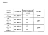
- FIG 6 illustrates a relationship between the control devices 14A to 14E, IP addresses, the power source control devices 16A to 16E managed by the control devices, and group IDs to which the power source control devices belong.
- the power source control devices 16A to 16E are classified as illustrated in FIG 6 .
- the power source control device 16A belongs to a group having a group ID "g0003”.
- the power source control devices 16B and 16C belong to a group having a group ID "g0001”.
- the power source control devices 16D and 16E belong to a group having a group ID "g0002”.
- the memory 144 of the control device 14A acting as a master stores information of the power source control device managed by the master, the group ID of the group to which the power source control device belongs, an IP address of the control device acting as a slave, information of the power source control device managed by each slave, and the group ID of the group to which the power source control device managed by each slave belongs.
- a name of each slave, an IP address of each slave, information of the power source control device managed by each slave, the ID of the group to which the power source control device managed by each slave belongs are associated with each other and are stored.
- the memory 144 of the control device 14A stores information of the power source control device 16A, the group ID "g0003" to which the power source control device 16A belongs, IP addresses "192. 168. 1. 12" to "192. 168. 1. 15" of the slaves, information of the power source control devices 16B to 16E managed by each slave, the group ID "g0001" to which the power source control devices 16B and 16C belong, and the group ID "g0002" to which the power source control devices 16D and 16E belong.
- the memory 144 of each slave stores the IP address of the master. That is, the memories 144 of the control devices 14B to 14E acting as a slave stores the IP address "192. 168. 1. 11" of the master. A user registers the above-mentioned information in the master and each slave through the client terminal 12.
- FIG 7 illustrates a flowchart of an operation of the control device 14A (the master).
- FIG 8 illustrates a flowchart of operations of the control devices 14B to 14E (the slaves).
- the control device 14A acts as the master, and the control devices 14B to 14E act as the slaves.
- the “frequency band” is a channel that is a frequency band needed for sending and receiving of data.
- the "communication timing” is a starting time and a cycle of wireless communication of each control device. The starting time and the cycle of the wireless communication is determined by the RTC 145 of each control device.
- the control device 14A acting as the master changes the channel and the communication timing of the wireless communication among all of the control devices including the control device 14A and all of the power source control devices to another channel and another communication timing that are free of interference.
- the CPU 143 of the master acquires channels and communication timings used for the wireless communication from all slaves via the wired network 13 as the process (step S001 of FIG 7 ).
- the CPU 143 of the master sends a request (that is, a GET method) indicated by the following URL to the slaves.
- the URL is the request of the channel and the communication. http:// ⁇ IP address of each slave>/nph.cgi/rfconfig.xml (1)
- the CPU 143 of the slave that receiving the request reports a channel and a communication timing used by the CPU 143 to the master by sending the following http message (2) to the master via the wired network 13 (YES in step S103 and S 104 of FIG 8 ).
- ⁇ channel>2 ⁇ /channel> ⁇ start>5 ⁇ /start> (2)
- the channel tag indicates the used channel.
- the start tag indicates a value in second at which the wireless communication starts.
- the interval tag indicates a value in second of the cycle of the wireless communication.
- the channel is 2, the value in second at which the wireless communication starts is 5, and the cycle is 10 seconds.
- the wireless communication starts at 5 seconds, 15 seconds, 25 seconds, 35 seconds, 45 seconds and 55 seconds in any one minute.
- the data transfer time of the wireless communication is 1 second in single wireless communication. A user can change the data transfer time of the wireless communication through the client terminal 12.
- the CPU 143 of the master generates a setting that is free of interference of the wireless communication as illustrated in FIG 9 based on the channels and the communication timings that are acquired by all slaves and are used for the wireless communication and the channel and the communication timing that the master uses in the wireless communication (step S002 of FIG 7 ).
- FIG9 illustrates an example in which 4 channels can be used, starting time is 5 or 10 (initial value is 5), and the cycle is 10 seconds.
- the number of the channel, the starting time and the cycle are not limited to values of FIG 9 .
- the cycle is fixed to 10 seconds. However, the cycle may be changed unless interference occurs in the wireless communication.
- the control devices 14A, 14B, 14C and 14D use channels that are different from each other. Therefore, the starting times of the control devices may be set to an identical value (for example, "5").
- the control device 14E uses the channel 1 that is the same as the channel of the control device 14A. Therefore, a difference between the value in second of the starting time of the control device 14A and the starting time of the control device 14E is five seconds.
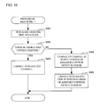
- the setting that is free of the interference of the wireless communication is generated. Therefore, the CPU 143 of the master performs the processes of FIG 10 with respect to the wireless communication of all control devices.
- the processes of FIG 10 is performed in the step S002 of FIG 7 . A description will be given of the processes of FIG. 10 .
- the CPU 143 of the master initializes the starting times and the cycles of the wireless communication (step S201). An initial value of the starting time of each control device is set to 5, and the cycle is set to 10 seconds. Next, it is determined whether the CPU 143 of the master can be used, and there is an unused channel (step S202). When it is determined as "YES" in the step S202, the CPU 143 of the master changes the channel used by an object control device to a detected channel that can be used and is not used (step S203), and the process is terminated.
- the CPU 143 of the master changes the channel used by the object control device to another channel in which the number of the assigned control devices is fewer (step S204). Moreover, the CPU 143 of the master changes the starting time of the wireless communication of the object control device to another starting time in which the number of the assigned control devices is fewer (step S205), and terminates the process.
- the channel that the control device 14A uses is already determined as the channel 1.
- the channels 2 to 4 are usable and unused. Therefore, in this case, the channel used by the control device 14B is changed to the channel 2.
- the channels 1 to 4 are already assigned to the control devices 14A to 14D. Therefore, in the step S202, it is determined that there are no usable and unused channels, In this case, the CPU 143 of the master changes the channel used by the control device 14E to another channel in which the number of assigned channels is fewer (step S204). In FIG 9 , the channels 1 to 4 are assigned to the control devices 14A to 14D.
- the channel in which the number of the assigned control devices is fewer is one of the channels 1 to 4.
- the CPU 143 of the master changes the starting time of the wireless communication to another starting time (that is, 10 seconds) in which the number of the assigned control devices is fewer (step S205).
- the setting that is free of interference of the wireless communication (that is, channels and communication timings) can be assigned to all control devices.
- the starting time of the wireless communication is changed.
- the cycle may be changed instead of the starting time of the wireless communication or in addition to the starting time of the wireless communication.
- the slave When the slave receives the above-mentioned URL request (3), that is, when the master requests the changing of the channel and the communication timing of the wireless communication (YES in step S105 of FIG 8 ), the slave changes the channel and the communication timing of the wireless communication thereof in accordance with the URL request (3) (step S106 of FIG 8 ). For example, in the control device 14B of FIG 9 , the channel is changed from the initial value to 2, the value in second of the starting time of the wireless communication is changed from the initial value to 5, and the cycle is changed from the initial value to 10 seconds. When each initial value is not changed, the initial values are kept.
- Each control device acquires electrical power information from the corresponding power source control device via wireless communication using the above-set channel after it is confirmed that the RTC 145 indicates the time designated by the above-mentioned communication timing (step S004 and S005 of FIG 7 and step S101 and step S102 of FIG 8 ).
- the master acquires the electrical power information from the power source control device (in this case, the power source control device 16A) performing the wireless communication.
- the slave acquires the electrical power information from the power source control device that performs the wireless communication with the slave.
- the CPU 143 of the master receiving the above-mentioned URL request (4) re-sets the channel and the communication timing used for all of wireless communication (YES in step S006 of FIG 7 ).
- the acquiring of a channel and a communication timing used for wireless communication step S001
- the generating of a setting of a channel and communication timing that is free of interference of wireless communication step S002
- the reporting of a generated channel and a generated communication timing to each slave step S003 are performed again.
- the user requests the electrical power information of the corresponding power source control device from each control device with use of the client terminal 12.
- the clients terminal 12 requests the electrical power information from each control device with use of the following URL request (5). http:// ⁇ IP address of control device>/nph.cgi/data.csv (5)
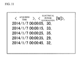
- the CPU 143 of the control device receiving the above-mentioned URL request (5) replies the electrical power information and the acquired time of the electrical power information stored therein to the client terminal 12 as illustrated in FIG 11 (step S007 and S008 of FIG 7 and step S107 and S108 of FIG 8 ).
- the user can request the electrical power information of every group from the master with use of the client terminal 12.
- the client terminal 12 requests the electrical power information of the power source control device belonging to the group ID "g0001" with use of the following URL request (6) from the master. http:// ⁇ IP address of master>/nph.cgi/g0001_data.csv (6)
- the CPU 143 of the master When the CPU 143 of the master receives the above-mentioned URL request (6), that is, when the electrical power information of the power source control device belonging to the group of the client terminal 12 is requested (YES in step S009 of FIG 7 ), the CPU 143 of the master uses the following URL requests (7) and (8), requests the electrical power information and an acquired time of the electrical power information from all slaves managing the power source control device belonging to the group thereof and acquires the electrical power information and the acquired time (step S010 of FIG 7 ). When there are a plurality of slaves, the CPU 143 of the master requests the electrical power information and the acquired time of the electrical power information from the slaves in order and acquires the electrical power information and the acquired time.
- all slaves that manage the power source control devices belonging to the group ID "g0001" are the control devices 14B and 14C of FIG 6 . http:// ⁇ IP address of control the device 14B>/nph.cgi/data.csv (7) http:// ⁇ IP address of control the device 14C>/nph.cgi/data.csv (8)
- the CPU 143 of the slave that receives the URL requests (7) and (8) replies the electrical power information and the acquired time of the electrical power information stored therein to the master (step S107 and step S108 of FIG 8 ). After that, the master replies the acquired electrical power information and the acquired time of the electrical power information to the client terminal 12 (step S011 of FIG 7 ).
- the CPU 143 of the slave uses the known IP address of the master and replies a re-direct instruction requesting "re-setting of the channel and the communication timing used by the control devices in the wireless communication” or "the electrical power information of every group” from the master to the client terminal 12 (step S109 of FIG 8 ).
- FIG 12 illustrates an example of the format of the electrical power information acquired from the power source control devices 16A and 16B.
- FIG 13 illustrates a sequence diagram describing processes for acquiring the electrical power information of the power source control devices belonging to the group ID "g0001".
- the client terminal 12 requests electrical power information of the power source control devices belonging to the group ID "g0001" from the master (the control device 14A) (step S301). In this case, the client terminal 12 sends the above-mentioned URL request (6) to the master.
- the CPU 143 of the master requests the electrical power information and the acquired time of the electrical power information to the slave (the control device 14B) that manages the power source control device 16B belonging to the group ID "g0001" (step S302).
- the CPU 143 of the master sends the above-mentioned URL request (7) to the slave (the control device 14B).
- the CPU 143 of the slave sends the electrical power information and the acquired time of the electrical power information stored therein to the master (step S303).
- the CPU 143 of the slave replies the electrical power information and the acquired time of the electrical power information to the master.
- the CPU 143 of the master requests the electrical power information and the acquired time of the electrical power information from the slave (the control device 14C) that manages the power source control device 16C belonging to the group ID "g0001" (step S304).
- the CPU 143 of the master sends the above-mentioned URL request (8) to the slave (the control device 14C).
- the CPU 143 of the slave replies the electrical power information and the acquired time of the electrical power information stored therein to the master (step S305).
- the CPU143 of the slave replies the electrical power information and the acquired time of the electrical power information acquired from the power source control device 16C to the master.
- the CPU 143 of the master replies the electrical power information and the acquired time of the electrical power information acquired from the slave (the control devices 14B and 14C) to the client terminal 12 (step S306).
- FIG 14 illustrates a sequence diagram describing processes in a case where the client terminal 12 requests the electrical power information of the power source control devices belonging to the group ID "g0001" from the slave (the control device 14B).
- the client terminal 12 requests the electrical power information of the power source control devices belonging to the group ID "g0001" from the slave (the control device 14B) (step S401). In this case, the client terminal 12 sends the following URL request (9) to the slave (the control device 14B). http:// ⁇ IP address of the control device 14B>/nph.cgi/g0001_data.csv (9)
- the CPU 143 of the slave uses the known IP address of the master and replies a re-direct instruction (10) requesting the electrical power information of the group ID "g0001" from the master to the client terminal 12 (step S402).
- the re-direct instruction (10) is the following instruction. Location:http:// ⁇ IP address of master>/nph.cgi/g0001_data.csv (10)
- the client terminal 12 requests the electrical power information of the power source control devices belonging to the group ID "g0001" from the master (step S403).
- the client terminal 12 sends the following URL request (11) to the master. http:// ⁇ IP address of master>/nph.cgi/g0001_data.csv (11)
- the CPU 143 of the control device 14A acting as the master acquires the information relating to the channels and the communication timing used for the wireless communication from the control devices 14B to 14E that are made to act as the slaves via the wired network 13 (step S001).
- the CPU 143 generates settings of the channel and the communication timing that are free of interference of the wireless communication between the control devices 14A to 14E and the power source control devices 16A to 16E based on information relating to the channel and the communication timing used by the master in the wireless communication and the acquired information relating to the channel and the communication timing used for the wireless communication (step S002).
- the CPU 143 reports the generated settings of the channel and the communication timing to the control devices 14B to 14E that are made to act as the slaves via the wired network 13 (step S003). Therefore, when a plurality of control devices perform wireless communication with a plurality of power source control devices, a channel and a communication timing that are free of interference of the wireless communication are automatically set in the plurality of control devices (a master and slaves). It is therefore possible to suppress interference of the wireless communication without a load of a user.
- step S006 When a slave is added or deleted (YES in step S006), information relating to the channel and the communication timing is acquired again (step S001). And, a setting of the channel and the communication timing that are free of interference of the wireless communication is generated again (step S002). And, the setting of the re-generated channel and the re-generated communication timing are reported to the slaves again (step S003). It is therefore possible to prevent the interference of the wireless communication when a slave is added or deleted.
- the master acquires the electrical power information from the power source control devices that perform wireless communication with the master (step S005). And, the master sends the acquired electrical power information to the client terminal 12 (step S008). It is therefore possible to send the electrical power information of the power source control devices performing the wireless communication with the master to the client terminal 12.
- the master has the memory 144 that associates IP addresses (destinations) of the slaves with information of the power source control devices managed by the slaves, and an ID of a group to which the power source control devices managed by the slaves belong and stores them.
- the client terminal 12 requests the electrical power information of the power source control devices belonging to a group from the master (step S009)
- the CPU 143 of the master acquires the electrical power information of the power source control devices belonging to the group from the slaves managing the power source control devices belonging to the group (step S010), and sends the acquired electrical power information to the client terminal 12 (step S011). It is therefore possible to send electrical power information of the power source control devices belonging to the group that is managed by the slaves to the client terminal 12.
- control devices 14A to 14E are respectively connected to the power source control devices 16A to 16E via wireless communication and respectively acquire electrical power information from the power source control devices 16A to 16E.
- connection destinations of the control devices 14A to 14E are not limited to the power source control devices 16A to 16E and may be a computer or a home electronics that are capable of performing wireless communication with the control devices 14A to 14E.
- the information which the control devices 14A to 14E acquire from the connection destinations is not limited to electrical power information and may be property information (such as a date of packing, a model number, or a product name) of the connection destinations.
Landscapes
- Engineering & Computer Science (AREA)
- Computer Networks & Wireless Communication (AREA)
- Signal Processing (AREA)
- Mobile Radio Communication Systems (AREA)
- Small-Scale Networks (AREA)
Abstract
Description
- The present invention relates to a control device and a communication system.
- Conventionally, there is known a power source control network in which a master logical device and a slave logical device are connected to each other (for example, see Japanese Laid-open Patent Publication No.
62-500269 - There is known a technology in which a client device having a power source control device is connected to a LAN (Local Area Network) together with a host computer (for example, see Japanese Laid-open Patent Publication No.
6-112960 2005-78174 - There is known a
communication system 1 that has aclient terminal 2,control devices 4A to 4E,wireless base devices 5A to 5E, and powersource control devices 6A to 6E, as illustrated inFIG 1 . In thecommunication system 1, theclient terminal 2 is connected to thecontrol devices 4A to 4E via awired network 3. Thecontrol devices 4A to 4E are respectively connected to thewireless base devices 5A to 5E. Thewireless base devices 5A to 5E are respectively connected to the powersource control devices 6A to 6E via wireless communication. Thewireless base devices 5A to 5E respectively communicate with the powersource control devices 6A to 6E with respect to electrical power information without wires. The electrical power information acquired by the powersource control devices 6A to 6E are respectively stored in thecontrol devices 4A to 4E via thewireless base devices 5A to 5E. - In the
communication system 1 ofFIG 1 , when a plurality of wireless communication is performed between the wireless base devices and the power source control devices with an identical channel and communication timings of the plurality of wireless communication are identical, collisions of the wireless communication may occur. In order to prevent the collisions of the wireless communication, it is necessary for a user to distribute the communication channels and the communication timings. Therefore, the user has to study combinations of the wireless communication and set the communication channels and the communication timings. Accordingly, there is a problem that the user has heavy workload. - In the
communication system 1 ofFIG 1 , the user can browse the electrical power information acquired by the powersource control devices 6A to 6E by accessing thecontrol devices 4A to 4E via theclient terminal 2. However, when the user wants to browse the electrical power information acquired by a specific power source control device, the user has to understand control devices that are connected to the specific power source control device. That is, there is a problem that the user has to understand connection relationships between the power source control devices and the control devices and thereby the user has heavy workload. - Accordingly, it is desirable to provide a control device and a communication system that are capable of suppressing an interfere of a wireless communication without putting a load to a user.
- According to an embodiment of one aspect of the present invention, there is provided a control device that performs wireless communication and is connected to another control device via a wired network including: an acquirer that acquires information relating to a channel and a communication timing used for wireless communication via the wired network from another control device that is made to act as a slave; a generator that generates a setting of a channel and a communication timing in which wireless communication performed by the another control device is free of interference, based on information relating to a channel and a communication timing used for wireless communication of the control device and information relating to the channel and the communication timing used for the wireless communication that are acquired by the acquirer; and a reporter that reports the setting of the channel and the timing generated by the generator to the another control device that is made to act as the slave via the wired network.
- According to an embodiment of one aspect of the present invention, there is provided a communication system including: a plurality of control devices that are connected to each other via a wired network; a plurality of opposing control devices that respectively perform wireless communication with the plurality of control devices; and an information processing device that is connected to the plurality of control devices via the wired network, and includes a setter that makes one of the plurality of control devices act as a master and makes the other control devices act as a slave, wherein: the master includes: an acquirer that acquires information relating to a channel and a communication timing used for a wireless communication via the wired network from the slave; a generator that generates a setting of a channel and a communication timing that is free of interference in the wireless communication between the plurality of control devices and the plurality of opposing control devices, based on information relating to a channel and a communication timing used for a wireless communication that the master uses and information relating to the channel and the communication timing used for the wireless communication that are acquired by the acquirer; and a reporter that reports the setting of the channel and the communication timing generated by the generator to the slave via the wired network, the slave includes a changer that changes a channel and a communication timing used for the wireless communication of the slave in accordance with the setting of the channel and the communication that are reported by the reporter.
-
-
FIG 1 illustrates a structure diagram of a conventional communication system; -
FIG 2 illustrates a structure diagram of a communication system in accordance with an embodiment; -
FIG 3 illustrates a block diagram of a client terminal; -
FIG 4 illustrates a block diagram of a control device; -
FIG 5 illustrates a block diagram of a power source control device; -
FIG 6 illustrates a relationship between a control device, an IP address, a power source control device and an ID of a group to which the power source control device belongs; -
FIG 7 illustrates a flow chart describing an operation of a control device (master); -
FIG 8 illustrates a flow chart describing an operation of a control device (slave); -
FIG 9 illustrates an example free of interference of wireless communication; -
FIG 10 illustrates a flowchart describing detailed processes of step S002 ofFIG 7 ; -
FIG 11 illustrates an example of electrical power information and an acquired time; -
FIG 12 illustrates an example of a format of electrical information; -
FIG 13 illustrates a sequence diagram describing a process for acquiring electrical power information of a power source control device belonging to a group ID "g0001"; and -
FIG 14 illustrates a sequence diagram describing a process in a case where a client terminal requests electrical power information of a power source control device belonging to a group ID "g001" from a slave. - A description will now be given of an embodiment of the present invention, by way of example only, with reference to the drawings.
-
FIG 2 illustrates a structure diagram of a communication system in accordance with an embodiment. As illustrated inFIG 2 , acommunication system 11 has aclient terminal 12 andcontrol devices 14A to 14E. Theclient terminal 12 is connected to thecontrol devices 14A to 14E via a wired network 13 (for example, a LAN). Thecontrol devices 14A to 14E have a function as a wireless base device for respectively communicating with powersource control devices 16A to 16E with wireless communication. Thecontrol devices 14A to 14E are respectively connected to the powersource control devices 16A to 16E via wireless communication. Thecontrol devices 14A to 14E respectively acquire electrical power information from the powersource control devices 16A to 16E acting as opposing control devices. The electrical power information is an example of possession information which the powersource control devices 16A to 16E possess. The powersource control devices 16A to 16E are respectively connected toloads 17A to 17E. Theloads 17A to 17E are electrical appliances and are computers, mobile phones, refrigerators, televisions or the like. -
FIG 3 illustrates a block diagram of theclient terminal 12. Theclient terminal 12 is an information processing device and is a computer or the like. Theclient terminal 12 has aCPU 121 that controls a whole thereof, amemory 122 and ahard disk drive 123 that store a predetermined program or data, adisplay device 124 that shows a program or data, aninput device 125 such as a key board or a mouse that inputs data, and a local area network interface (LAN IF) 126. - The
hard disk drive 123 stores a setting program that makes one of thecontrol devices 14A to 14E act as a master and makes the others act as slaves. TheCPU 121 reads the setting program, writes the setting program in thememory 122, and executes the setting program. Thus, theCPU 121 makes one of thecontrol devices 14A to 14E act as a master and makes the others act as slaves in accordance with an instruction from theinput device 125. The setting of the master and the slaves can be changed through theinput device 125. In the embodiment, thecontrol device 14A is made to act as a master, and thecontrol devices 14B to 14E are made to act as slaves. The LAN IF 126 is connected to thewired network 13 via a LAN cable. -
FIG 4 illustrates a block diagram of a structure of thecontrol device 14A. Thecontrol devices 14B to 14E have the same structure as thecontrol device 14A.FIG 5 illustrates a block diagram of a structure of the powersource control device 16A. The powersource control devices 16B to 16E have the same structure as the powersource control device 16A. - The
control device 14A ofFIG 4 has a local area network interface (LAN IF) 141, a PHY (Physical Layer Chip)module 142, aCPU 143, amemory 144, a built-in clock (real time clock; RTC) 145, afrequency convertor 146 and anantenna 147. - For example, the LAN
IF 141 and theCPU 143 of thecontrol device 14A acting as a master acts as an acquirer, a reporter and a sender. TheCPU 143 of the master acts as a generator, for example. Thefrequency convertor 146, theantenna 147 and theCPU 143 of the master act as a second acquirer, for example. Thememory 144 of the master acts as a holder, for example. EachCPU 143 of thecontrol devices 14B to 14E acting as slaves acts as a changer, for example. Thefrequency convertor 146, theantenna 147 and theCPU 143 of the slaves act as a third acquirer, for example. The LAN IF 141 and theCPU 143 of the slaves act as a second sender, for example. - The power
source control device 16A ofFIG. 5 has anantenna 161, afrequency convertor 162, aCPU 163, amemory 164, anelectrical power measure 165, aplug 166 and anelectrical power acquirer 167. - In
FIG 4 , theLAN IF 141 is connected to the wirednetwork 13 via a LAN cable. ThePHY module 142 performs a conversion between data and an electrical signal. TheCPU 143 controls an entire operation of the control device. Thememory 144 stores data, information and so on. TheRTC 145 measures a time. The times of thecontrol devices 14A to 14E are consistent with each other. Thefrequency convertor 146 changes a frequency band used for the communication with the powersource control device 16A. Theantenna 147 is used for sending information to the powersource control device 16A or receiving information from the powersource control device 16A. - In
FIG. 5 , theantenna 161 is used for sending information to thecontrol device 14A or receiving information from thecontrol device 14A. Thefrequency convertor 162 changes a frequency band used for the communication with thecontrol device 14A. TheCPU 163 controls an entire operation of the power source control device. Thememory 164 stores data, information and so on. Theelectrical power measure 165 measures electrical power information of a load (load 17A) such as a consumption power, a consumption current or a voltage. Theplug 166 supplies an electrical power to the connected load via theelectrical power acquirer 167. Theelectrical power acquirer 167 is connected to an outer power source and acquires the electrical power supplied to the load from the outer power source. - The
control device 14A and the powersource control device 16A communicate with each other through wireless communication with use of theantennas frequency convertors source control device 16A supplies electrical power to the load connected to theplug 166 via theelectrical power acquirer 167 and measures electrical power information of the load such as the consumption power, the consumption current or the voltage. Thecontrol devices 14A to 14E are connected to theclient terminal 12 via the LAN IF 141 and the wirednetwork 13 and communicate with each other with use of a http protocol. In the embodiment, a header or the like needed for the http protocol is omitted. - The power
source control devices 16A to 16E respectively supply electrical power to theloads 17A to 17E and respectively measure electrical power [W] consumed by theloads 17A to 17E. Thecontrol devices 14A to 14E respectively perform wireless communication with the powersource control devices 16A to 16E and respectively acquire the electrical power information from the power source control devices. The electrical power information is a value of the consumption power [W] of the load connected to each of the power source control devices. The electrical power information may be a value of the consumption voltage or the consumption current of the load connected to each of the power source control devices. Eachmemory 144 of thecontrol devices 14A to 14E stores the electrical power information acquired thereby together with the time of theRTC 145. -
FIG 6 illustrates a relationship between thecontrol devices 14A to 14E, IP addresses, the powersource control devices 16A to 16E managed by the control devices, and group IDs to which the power source control devices belong. - The power
source control devices 16A to 16E are classified as illustrated inFIG 6 . The powersource control device 16A belongs to a group having a group ID "g0003". The powersource control devices source control devices - The
memory 144 of thecontrol device 14A acting as a master stores information of the power source control device managed by the master, the group ID of the group to which the power source control device belongs, an IP address of the control device acting as a slave, information of the power source control device managed by each slave, and the group ID of the group to which the power source control device managed by each slave belongs. A name of each slave, an IP address of each slave, information of the power source control device managed by each slave, the ID of the group to which the power source control device managed by each slave belongs are associated with each other and are stored. - In concrete, the
memory 144 of thecontrol device 14A stores information of the powersource control device 16A, the group ID "g0003" to which the powersource control device 16A belongs, IP addresses "192. 168. 1. 12" to "192. 168. 1. 15" of the slaves, information of the powersource control devices 16B to 16E managed by each slave, the group ID "g0001" to which the powersource control devices source control devices - The
memory 144 of each slave stores the IP address of the master. That is, thememories 144 of thecontrol devices 14B to 14E acting as a slave stores the IP address "192. 168. 1. 11" of the master. A user registers the above-mentioned information in the master and each slave through theclient terminal 12. -
FIG 7 illustrates a flowchart of an operation of thecontrol device 14A (the master).FIG 8 illustrates a flowchart of operations of thecontrol devices 14B to 14E (the slaves). In this case, thecontrol device 14A acts as the master, and thecontrol devices 14B to 14E act as the slaves. - Just after starting of the
communication system 11, thecontrol devices 14A to 14E and the powersource control devices 16A to 16E do not perform a negotiation in a frequency band at a communication timing used for wireless communication. Therefore, thecontrol devices 14A to 14E and the powersource control devices 16A to 16E may interfere with each other. The "frequency band" is a channel that is a frequency band needed for sending and receiving of data. The "communication timing" is a starting time and a cycle of wireless communication of each control device. The starting time and the cycle of the wireless communication is determined by theRTC 145 of each control device. - The
control device 14A acting as the master changes the channel and the communication timing of the wireless communication among all of the control devices including thecontrol device 14A and all of the power source control devices to another channel and another communication timing that are free of interference. TheCPU 143 of the master acquires channels and communication timings used for the wireless communication from all slaves via the wirednetwork 13 as the process (step S001 ofFIG 7 ). In concrete, theCPU 143 of the master sends a request (that is, a GET method) indicated by the following URL to the slaves. The URL is the request of the channel and the communication.
http://<IP address of each slave>/nph.cgi/rfconfig.xml (1) - The
CPU 143 of the slave that receiving the request reports a channel and a communication timing used by theCPU 143 to the master by sending the following http message (2) to the master via the wired network 13 (YES in step S103 and S 104 ofFIG 8 ).
<channel>2</channel>
<start>5</start> (2)
<interval> 10</interval> - In the http message (2), the channel tag indicates the used channel. The start tag indicates a value in second at which the wireless communication starts. The interval tag indicates a value in second of the cycle of the wireless communication. In the above-mentioned example, the channel is 2, the value in second at which the wireless communication starts is 5, and the cycle is 10 seconds. When the value in second is 5 and the cycle is 10 seconds, the wireless communication starts at 5 seconds, 15 seconds, 25 seconds, 35 seconds, 45 seconds and 55 seconds in any one minute. The data transfer time of the wireless communication is 1 second in single wireless communication. A user can change the data transfer time of the wireless communication through the
client terminal 12. - The
CPU 143 of the master generates a setting that is free of interference of the wireless communication as illustrated inFIG 9 based on the channels and the communication timings that are acquired by all slaves and are used for the wireless communication and the channel and the communication timing that the master uses in the wireless communication (step S002 ofFIG 7 ).FIG9 illustrates an example in which 4 channels can be used, starting time is 5 or 10 (initial value is 5), and the cycle is 10 seconds. The number of the channel, the starting time and the cycle are not limited to values ofFIG 9 . In the case ofFIG 9 , the cycle is fixed to 10 seconds. However, the cycle may be changed unless interference occurs in the wireless communication. InFIG. 9 , thecontrol devices control device 14E uses thechannel 1 that is the same as the channel of thecontrol device 14A. Therefore, a difference between the value in second of the starting time of thecontrol device 14A and the starting time of thecontrol device 14E is five seconds. - The setting that is free of the interference of the wireless communication is generated. Therefore, the
CPU 143 of the master performs the processes ofFIG 10 with respect to the wireless communication of all control devices. The processes ofFIG 10 is performed in the step S002 ofFIG 7 . A description will be given of the processes ofFIG. 10 . - The
CPU 143 of the master initializes the starting times and the cycles of the wireless communication (step S201). An initial value of the starting time of each control device is set to 5, and the cycle is set to 10 seconds. Next, it is determined whether theCPU 143 of the master can be used, and there is an unused channel (step S202). When it is determined as "YES" in the step S202, theCPU 143 of the master changes the channel used by an object control device to a detected channel that can be used and is not used (step S203), and the process is terminated. - When it is determined as "NO" in the step S202, the
CPU 143 of the master changes the channel used by the object control device to another channel in which the number of the assigned control devices is fewer (step S204). Moreover, theCPU 143 of the master changes the starting time of the wireless communication of the object control device to another starting time in which the number of the assigned control devices is fewer (step S205), and terminates the process. - For example, when the channel of the
control device 14B acting as a slave is determined, the channel that thecontrol device 14A uses is already determined as thechannel 1. However, thechannels 2 to 4 are usable and unused. Therefore, in this case, the channel used by thecontrol device 14B is changed to thechannel 2. For example, when the channel of thecontrol device 14E acting as a slave is determined, thechannels 1 to 4 are already assigned to thecontrol devices 14A to 14D. Therefore, in the step S202, it is determined that there are no usable and unused channels, In this case, theCPU 143 of the master changes the channel used by thecontrol device 14E to another channel in which the number of assigned channels is fewer (step S204). InFIG 9 , thechannels 1 to 4 are assigned to thecontrol devices 14A to 14D. Therefore, the channel in which the number of the assigned control devices is fewer is one of thechannels 1 to 4. Moreover, theCPU 143 of the master changes the starting time of the wireless communication to another starting time (that is, 10 seconds) in which the number of the assigned control devices is fewer (step S205). - With the processes of
FIG 10 , the setting that is free of interference of the wireless communication (that is, channels and communication timings) can be assigned to all control devices. In the step S205, the starting time of the wireless communication is changed. However, unless interfere occurs in the wireless communication, the cycle may be changed instead of the starting time of the wireless communication or in addition to the starting time of the wireless communication. - As illustrated in
FIG 7 , theCPU 143 of the master reports the channel and the communication timing of each wireless communication with the following URL request (3) to each slave via the wired network 13 (step S003 ofFIG 7 ). http://<IP address of each slave>/nph.cgi?channel=2&start=5&interval=10 (3) - When the slave receives the above-mentioned URL request (3), that is, when the master requests the changing of the channel and the communication timing of the wireless communication (YES in step S105 of
FIG 8 ), the slave changes the channel and the communication timing of the wireless communication thereof in accordance with the URL request (3) (step S106 ofFIG 8 ). For example, in thecontrol device 14B ofFIG 9 , the channel is changed from the initial value to 2, the value in second of the starting time of the wireless communication is changed from the initial value to 5, and the cycle is changed from the initial value to 10 seconds. When each initial value is not changed, the initial values are kept. - Each control device acquires electrical power information from the corresponding power source control device via wireless communication using the above-set channel after it is confirmed that the
RTC 145 indicates the time designated by the above-mentioned communication timing (step S004 and S005 ofFIG 7 and step S101 and step S102 ofFIG 8 ). In the step S005 ofFIG 7 , the master acquires the electrical power information from the power source control device (in this case, the powersource control device 16A) performing the wireless communication. In the step S102 ofFIG 8 , the slave acquires the electrical power information from the power source control device that performs the wireless communication with the slave. - When the channel and the communication timing used for the wireless communication are re-set by adding a slave or deleting a slave, the
client terminal 12 requests a re-setting of the channel used for the wireless communication and the communication timing from the master with use of the following URL request.
http://<IP address of master>/nph.cgi/dorfconfig=1 (4) - The
CPU 143 of the master receiving the above-mentioned URL request (4) re-sets the channel and the communication timing used for all of wireless communication (YES in step S006 ofFIG 7 ). In this case, the acquiring of a channel and a communication timing used for wireless communication (step S001), the generating of a setting of a channel and communication timing that is free of interference of wireless communication (step S002) and the reporting of a generated channel and a generated communication timing to each slave (step S003) are performed again. - The user requests the electrical power information of the corresponding power source control device from each control device with use of the
client terminal 12. The clients terminal 12 requests the electrical power information from each control device with use of the following URL request (5).
http://<IP address of control device>/nph.cgi/data.csv (5) - The
CPU 143 of the control device receiving the above-mentioned URL request (5) replies the electrical power information and the acquired time of the electrical power information stored therein to theclient terminal 12 as illustrated inFIG 11 (step S007 and S008 ofFIG 7 and step S107 and S108 ofFIG 8 ). - The user can request the electrical power information of every group from the master with use of the
client terminal 12. For example, theclient terminal 12 requests the electrical power information of the power source control device belonging to the group ID "g0001" with use of the following URL request (6) from the master.
http://<IP address of master>/nph.cgi/g0001_data.csv (6) - When the
CPU 143 of the master receives the above-mentioned URL request (6), that is, when the electrical power information of the power source control device belonging to the group of theclient terminal 12 is requested (YES in step S009 ofFIG 7 ), theCPU 143 of the master uses the following URL requests (7) and (8), requests the electrical power information and an acquired time of the electrical power information from all slaves managing the power source control device belonging to the group thereof and acquires the electrical power information and the acquired time (step S010 ofFIG 7 ). When there are a plurality of slaves, theCPU 143 of the master requests the electrical power information and the acquired time of the electrical power information from the slaves in order and acquires the electrical power information and the acquired time. In this case, all slaves that manage the power source control devices belonging to the group ID "g0001" are thecontrol devices FIG 6 .
http://<IP address of control thedevice 14B>/nph.cgi/data.csv (7)
http://<IP address of control thedevice 14C>/nph.cgi/data.csv (8) - The
CPU 143 of the slave that receives the URL requests (7) and (8) replies the electrical power information and the acquired time of the electrical power information stored therein to the master (step S107 and step S108 ofFIG 8 ). After that, the master replies the acquired electrical power information and the acquired time of the electrical power information to the client terminal 12 (step S011 ofFIG 7 ). - On the other hand, when the user requests "re-setting of the channel and the communication timing used by the control device in the wireless communication" or "the electrical power information of every group" from the slave through the client terminal 12 (NO in step S107 of
FIG 8 ), theCPU 143 of the slave uses the known IP address of the master and replies a re-direct instruction requesting "re-setting of the channel and the communication timing used by the control devices in the wireless communication" or "the electrical power information of every group" from the master to the client terminal 12 (step S109 ofFIG 8 ). - When the electrical power information of the power source control devices are replied to the
client terminal 12, the user sets a response format to the master in advance through theclient terminal 12.FIG 12 illustrates an example of the format of the electrical power information acquired from the powersource control devices -
FIG 13 illustrates a sequence diagram describing processes for acquiring the electrical power information of the power source control devices belonging to the group ID "g0001". - The
client terminal 12 requests electrical power information of the power source control devices belonging to the group ID "g0001" from the master (thecontrol device 14A) (step S301). In this case, theclient terminal 12 sends the above-mentioned URL request (6) to the master. - The
CPU 143 of the master requests the electrical power information and the acquired time of the electrical power information to the slave (thecontrol device 14B) that manages the powersource control device 16B belonging to the group ID "g0001" (step S302). In this case, theCPU 143 of the master sends the above-mentioned URL request (7) to the slave (thecontrol device 14B). TheCPU 143 of the slave (thecontrol device 14B) sends the electrical power information and the acquired time of the electrical power information stored therein to the master (step S303). In concrete, theCPU 143 of the slave (thecontrol device 14B) replies the electrical power information and the acquired time of the electrical power information to the master. - Next, the
CPU 143 of the master requests the electrical power information and the acquired time of the electrical power information from the slave (thecontrol device 14C) that manages the powersource control device 16C belonging to the group ID "g0001" (step S304). In this case, theCPU 143 of the master sends the above-mentioned URL request (8) to the slave (thecontrol device 14C). TheCPU 143 of the slave (thecontrol device 14C) replies the electrical power information and the acquired time of the electrical power information stored therein to the master (step S305). In concrete, the CPU143 of the slave (thecontrol device 14C) replies the electrical power information and the acquired time of the electrical power information acquired from the powersource control device 16C to the master. - The
CPU 143 of the master replies the electrical power information and the acquired time of the electrical power information acquired from the slave (thecontrol devices -
FIG 14 illustrates a sequence diagram describing processes in a case where theclient terminal 12 requests the electrical power information of the power source control devices belonging to the group ID "g0001" from the slave (thecontrol device 14B). - The
client terminal 12 requests the electrical power information of the power source control devices belonging to the group ID "g0001" from the slave (thecontrol device 14B) (step S401). In this case, theclient terminal 12 sends the following URL request (9) to the slave (thecontrol device 14B).
http://<IP address of thecontrol device 14B>/nph.cgi/g0001_data.csv (9) - The
CPU 143 of the slave (thecontrol device 14B) uses the known IP address of the master and replies a re-direct instruction (10) requesting the electrical power information of the group ID "g0001" from the master to the client terminal 12 (step S402). For example, the re-direct instruction (10) is the following instruction.
Location:http://<IP address of master>/nph.cgi/g0001_data.csv (10) - After that, the
client terminal 12 requests the electrical power information of the power source control devices belonging to the group ID "g0001" from the master (step S403). In this case, theclient terminal 12 sends the following URL request (11) to the master.
http://<IP address of master>/nph.cgi/g0001_data.csv (11) - With the processes of
FIG 14 , even if the user requests the electrical power information of the power source control device belonging to an arbitrary group ID from the slave, the user re-requests the electrical power information from the master. Therefore, the user can get an expected result. In other words, requests that the slave cannot handle can be introduced to the master that is a correct request destination. - As mentioned above, in the embodiment, the
CPU 143 of thecontrol device 14A acting as the master acquires the information relating to the channels and the communication timing used for the wireless communication from thecontrol devices 14B to 14E that are made to act as the slaves via the wired network 13 (step S001). TheCPU 143 generates settings of the channel and the communication timing that are free of interference of the wireless communication between thecontrol devices 14A to 14E and the powersource control devices 16A to 16E based on information relating to the channel and the communication timing used by the master in the wireless communication and the acquired information relating to the channel and the communication timing used for the wireless communication (step S002). And, theCPU 143 reports the generated settings of the channel and the communication timing to thecontrol devices 14B to 14E that are made to act as the slaves via the wired network 13 (step S003). Therefore, when a plurality of control devices perform wireless communication with a plurality of power source control devices, a channel and a communication timing that are free of interference of the wireless communication are automatically set in the plurality of control devices (a master and slaves). It is therefore possible to suppress interference of the wireless communication without a load of a user. - When a slave is added or deleted (YES in step S006), information relating to the channel and the communication timing is acquired again (step S001). And, a setting of the channel and the communication timing that are free of interference of the wireless communication is generated again (step S002). And, the setting of the re-generated channel and the re-generated communication timing are reported to the slaves again (step S003). It is therefore possible to prevent the interference of the wireless communication when a slave is added or deleted.
- And, when the
client terminal 12 connected to the master via the wirednetwork 13 requests the electrical power information from the master (YES in step S007), the master acquires the electrical power information from the power source control devices that perform wireless communication with the master (step S005). And, the master sends the acquired electrical power information to the client terminal 12 (step S008). It is therefore possible to send the electrical power information of the power source control devices performing the wireless communication with the master to theclient terminal 12. - Moreover, the master has the
memory 144 that associates IP addresses (destinations) of the slaves with information of the power source control devices managed by the slaves, and an ID of a group to which the power source control devices managed by the slaves belong and stores them. When theclient terminal 12 requests the electrical power information of the power source control devices belonging to a group from the master (step S009), theCPU 143 of the master acquires the electrical power information of the power source control devices belonging to the group from the slaves managing the power source control devices belonging to the group (step S010), and sends the acquired electrical power information to the client terminal 12 (step S011). It is therefore possible to send electrical power information of the power source control devices belonging to the group that is managed by the slaves to theclient terminal 12. - In the embodiment, the
control devices 14A to 14E are respectively connected to the powersource control devices 16A to 16E via wireless communication and respectively acquire electrical power information from the powersource control devices 16A to 16E. However, connection destinations of thecontrol devices 14A to 14E are not limited to the powersource control devices 16A to 16E and may be a computer or a home electronics that are capable of performing wireless communication with thecontrol devices 14A to 14E. The information which thecontrol devices 14A to 14E acquire from the connection destinations is not limited to electrical power information and may be property information (such as a date of packing, a model number, or a product name) of the connection destinations. - As described above, the embodiments of the present invention are explained in detail. However, the present invention is not limited to the specifically disclosed embodiment and variations but may include other embodiments and variations without departing from the scope of the present invention.
Claims (13)
- A control device that is configured to perform wireless communication and is connected to another control device via a wired network comprising:an acquirer configured to acquire information relating to a channel and a communication timing used for wireless communication via the wired network from another control device that is made to act as a slave;a generator configured to generate a setting of a channel and a communication timing in which wireless communication performed by the another control device is free of interference, based on information relating to a channel and a communication timing used for wireless communication of the control device and information relating to the channel and the communication timing used for the wireless communication that are acquired by the acquirer; anda reporter configured to report the setting of the channel and the timing generated by the generator to the another control device that is made to act as the slave via the wired network.
- The control device as claimed in claim 1, wherein:the communication timing is a starting time and a cycle of wireless communication;when there is a usable and unused channel when generating the setting, the generator is configured to set a channel that is used by an object control device to the usable and unused channel; andwhen there is no usable and unused channel when generating the setting, the generator is configured to set the channel that is used by the object control device to a channel in which a number of assigned control devices is less and to set a starting time of the wireless communication to a starting time in which a number of assigned control devices is less.
- The control device as claimed in claim 1 or 2, wherein when another control device is added to the wired network or is deleted from the wired network, the acquirer is configured to re-acquire the information relating to the channel and the communication timing from another control device connected to the wired network, the generator is configured to re-generate the setting of the channel and the communication timing that is free of interference of the wireless communication performed by the another control device, and the reporter is configured to re-report the re-generated setting of the channel and the communication timing to the control device that is made to act as the slave.
- The control device as claimed in any of claims 1 to 3 further comprising:a second acquirer configured to acquire possession information possessed by an opposing control device that performs wireless communication with the control device when information is requested from an information processing device that is connected to the control device via the wired network; anda sender configured to send the possession information acquired by the second acquirer to the information processing device.
- The control device as claimed in claim 4 further comprising a holder configured to associate with each other a destination of the slave, information of the opposing control device managed by the slave, and information of a group to which the opposing control device managed by the slave belongs, and holds the associated information,
wherein:when possession information of an opposing control device belonging to a group indicated by the information processing device is requested, the second acquirer is configured to acquire the possession information of the opposing control device belonging to the group from a slave that manages the opposing control device belonging to the group; andthe sender is configured to send the possession information acquired by the second acquirer to the information processing device. - A communication system comprising:a plurality of control devices that are connected to each other via a wired network;a plurality of opposing control devices that are configured to respectively perform wireless communication with the plurality of control devices; andan information processing device that is connected to the plurality of control devices via the wired network, and includes a setter configured to make one of the plurality of control devices act as a master and to make the other control devices act as a slave,wherein:the master comprises:an acquirer configured to acquire information relating to a channel and a communication timing used for a wireless communication via the wired network from the slave;a generator configured to generate a setting of a channel and a communication timing that is free of interference in the wireless communication between the plurality of control devices and the plurality of opposing control devices, based on information relating to a channel and a communication timing used for a wireless communication that the master uses and information relating to the channel and the communication timing used for the wireless communication that are acquired by the acquirer; anda reporter configured to report the setting of the channel and the communication timing generated by the generator to the slave via the wired network, andthe slave comprises a changer configured to change a channel and a communication timing used for the wireless communication of the slave in accordance with the setting of the channel and the communication that are reported by the reporter.
- The communication system as claimed in claim 6, wherein:the communication timing is a starting time and a cycle of a wireless communication;when there is a usable and unused channel when generating the setting, the generator is configured to set a channel that is used by an object control device to the usable and unused channel; andwhen there is no usable and unused channel when generating the setting, the generator is configured to set the channel that is used by the object control device to a channel in which a number of assigned control devices is less and to set a starting time of the wireless communication to a starting time in which a number of assigned control devices is less.
- The communication system as claimed in claim 6 or 7, wherein when the slave is added to the wired network or is deleted from the wired network, the acquirer is configured to re-acquire the information relating to the channel and the communication timing from another slave connected to the wired network, the generator is configured to re-generate the setting of the channel and the communication timing that is free of interference of the wireless communication performed by the plurality of control devices, and the reporter is configured to re-report the re-generated setting of the channel and the communication timing to a control device that is made to act as the slave.
- The communication system as claimed in any of claims 6 to 8, wherein:the master comprises:a second acquirer configured to acquire possession information of an opposing control device that performs a wireless communication with the master when acquiring of information from the opposing control device performing the wireless communication is requested; anda first sender configured to send the possession information acquired by the second acquirer to the information processing device, andthe slave comprises:a third acquirer configured to acquire possession information of an opposing control device that performs a wireless communication with the slave when the possession information is requested; anda second sender configured to send the possession information acquired by the third acquirer to the information processing device.
- The communication system as claimed in claim 9, wherein:the master comprises:a holder configured to associate with each other a destination of the slave, information of the opposing control device managed by the slave, and information of a group to which the opposing control device managed by the slave belongs, and to hold the associated information,wherein:when possession information of the opposing control device belonging to a group indicated by the information processing device is requested, the second acquirer is configured to acquire possession information of the opposing control device belonging to the group from a slave that manages the opposing control device belonging to the group; andthe first sender is configured to send the possession information acquired by the second acquirer to the information processing device.
- The communication system as claimed in claim 10, wherein when the information processing device requests a re-setting of the channel and the communication timing used for the wireless communication or electrical power information of the opposing control device belonging to the group from the slave, the second sender of the slave is configured to send back to the information processing device a re-direct instruction requesting the resetting of the channel and the communication timing used for the wireless communication or electrical power information of an opposing control device belonging to the group from the master by using a destination of the master.
- A method of performing wireless communication, wherein a control device is connected to another control device via a wired network, the method comprising:acquiring information relating to a channel and a communication timing used for wireless communication via the wired network from another control device that is made to act as a slave;generating a setting of a channel and a communication timing in which wireless communication performed by the another control device is free of interference, based on information relating to a channel and a communication timing used for wireless communication of the control device and information relating to the channel and the communication timing used for the wireless communication that are acquired by the acquirer; andreporting the setting of the channel and the timing generated by the generator to the another control device that is made to act as the slave via the wired network.
- A communication method for use in a system comprising:a plurality of control devices that are connected to each other via a wired network;a plurality of opposing control devices that are configured to respectively perform wireless communication with the plurality of control devices; andan information processing device that is connected to the plurality of control devices via the wired network, and includes a setter configured to make one of the plurality of control devices act as a master and to make the other control devices act as a slave,wherein:the master acquires information relating to a channel and a communication timing used for a wireless communication via the wired network from the slave, generates a setting of a channel and a communication timing that is free of interference in the wireless communication between the plurality of control devices and the plurality of opposing control devices, based on information relating to a channel and a communication timing used for a wireless communication that the master uses and information relating to the channel and the communication timing used for the wireless communication that are acquired by the acquirer and reports the setting of the channel and the communication timing generated by the generator to the slave via the wired network; andthe slave changes a channel and a communication timing used for the wireless communication of the slave in accordance with the setting of the channel and the communication that are reported by the reporter.
Applications Claiming Priority (1)
| Application Number | Priority Date | Filing Date | Title |
|---|---|---|---|
| JP2014088460A JP6352672B2 (en) | 2014-04-22 | 2014-04-22 | Control device and communication system |
Publications (2)
| Publication Number | Publication Date |
|---|---|
| EP2938143A1 true EP2938143A1 (en) | 2015-10-28 |
| EP2938143B1 EP2938143B1 (en) | 2018-10-17 |
Family
ID=53181049
Family Applications (1)
| Application Number | Title | Priority Date | Filing Date |
|---|---|---|---|
| EP15164331.9A Not-in-force EP2938143B1 (en) | 2014-04-22 | 2015-04-20 | Control device and communication system |
Country Status (4)
| Country | Link |
|---|---|
| US (2) | US10143014B2 (en) |
| EP (1) | EP2938143B1 (en) |
| JP (1) | JP6352672B2 (en) |
| CN (1) | CN105005374B (en) |
Families Citing this family (2)
| Publication number | Priority date | Publication date | Assignee | Title |
|---|---|---|---|---|
| US10212658B2 (en) * | 2016-09-30 | 2019-02-19 | Kinetic Technologies | Systems and methods for managing communication between devices |
| US10757484B2 (en) | 2017-01-05 | 2020-08-25 | Kinetic Technologies | Systems and methods for pulse-based communication |
Citations (5)
| Publication number | Priority date | Publication date | Assignee | Title |
|---|---|---|---|---|
| JPS62500269A (en) | 1984-09-25 | 1987-01-29 | バロ−ス・コ−ポレ−ション | Power control network with reliable communication protocols |
| JPH06112960A (en) | 1992-09-29 | 1994-04-22 | Brother Ind Ltd | Power control device |
| JP2005078174A (en) | 2003-08-28 | 2005-03-24 | Fuji Electric Fa Components & Systems Co Ltd | Communication system using uninterruptible power supply |
| US20120243638A1 (en) * | 2005-10-26 | 2012-09-27 | Alexander Maltsev | Systems for communicating using multiple frequency bands in a wireless network |
| WO2013128902A1 (en) * | 2012-03-01 | 2013-09-06 | パナソニック株式会社 | Cordless handset for power management system and power management system |
Family Cites Families (38)
| Publication number | Priority date | Publication date | Assignee | Title |
|---|---|---|---|---|
| KR100239397B1 (en) * | 1996-12-02 | 2000-01-15 | 김영환 | Call channel distribution selection method of code division multiple access base station |
| US6069871A (en) * | 1997-07-21 | 2000-05-30 | Nortel Networks Corporation | Traffic allocation and dynamic load balancing in a multiple carrier cellular wireless communication system |
| US6922557B2 (en) | 2000-10-18 | 2005-07-26 | Psion Teklogix Inc. | Wireless communication system |
| JP3671880B2 (en) * | 2001-07-18 | 2005-07-13 | ソニー株式会社 | COMMUNICATION SYSTEM AND METHOD, INFORMATION PROCESSING DEVICE AND METHOD, COMMUNICATION TERMINAL AND METHOD, EXPANSION DEVICE, AND PROGRAM |
| JP3888205B2 (en) * | 2002-04-04 | 2007-02-28 | セイコーエプソン株式会社 | Wireless communication management device |
| US7852796B2 (en) * | 2002-05-13 | 2010-12-14 | Xudong Wang | Distributed multichannel wireless communication |
| JP2004048356A (en) * | 2002-07-11 | 2004-02-12 | Sony Corp | Access point arbitration device and data communication system using the same |
| US7818480B2 (en) * | 2002-08-29 | 2010-10-19 | Raritan Americas, Inc. | Wireless management of remote devices |
| JP2004260382A (en) * | 2003-02-25 | 2004-09-16 | Iwatsu Electric Co Ltd | Synchronization method between base stations |
| JP3817531B2 (en) * | 2003-07-22 | 2006-09-06 | キヤノン株式会社 | Control unit of radio communication device, radio communication device, and control method |
| JP4354258B2 (en) * | 2003-11-21 | 2009-10-28 | 三菱電機株式会社 | Mobile communication system |
| US6990335B1 (en) * | 2004-11-18 | 2006-01-24 | Charles G. Shamoon | Ubiquitous connectivity and control system for remote locations |
| EP1662727B1 (en) * | 2004-11-30 | 2013-04-03 | Canon Kabushiki Kaisha | Control of sequentially communicating with devices included in a plurality of networks (e.g. piconets) |
| JP2007053627A (en) * | 2005-08-18 | 2007-03-01 | Mitsubishi Electric Corp | Wireless communication system |
| EP1806942A1 (en) * | 2006-01-05 | 2007-07-11 | Alcatel Lucent | Method of semidynamic centralized interference coordination for cellular systems |
| US8491159B2 (en) * | 2006-03-28 | 2013-07-23 | Wireless Environment, Llc | Wireless emergency lighting system |
| US8265712B2 (en) * | 2007-04-13 | 2012-09-11 | Nokia Corporation | Multiradio power aware traffic management |
| WO2009119850A1 (en) * | 2008-03-27 | 2009-10-01 | 京セラ株式会社 | Composite optical transmission substrate and optical module |
| US8442002B2 (en) * | 2008-09-05 | 2013-05-14 | Nec Europe Ltd. | Method for operating a multi-cell radio system and a multi-cell radio system |
| WO2010050532A1 (en) | 2008-10-28 | 2010-05-06 | アイコム株式会社 | Wireless communication system, relay system, repeater devices and synchronization method |
| US8432063B2 (en) * | 2010-02-18 | 2013-04-30 | Enocean Gmbh | Multi-channel power controller with switching offset |
| JP2011182346A (en) * | 2010-03-04 | 2011-09-15 | Sharp Corp | Radio telemetry system |
| JP5177911B2 (en) * | 2010-05-06 | 2013-04-10 | Necアクセステクニカ株式会社 | Wireless communication device management method and wireless communication device |
| CN102255641B (en) * | 2010-05-20 | 2014-09-03 | 华为技术有限公司 | Method and device for updating CoMP (Coordinated Multi-point Transmission) sending set |
| CN101873709B (en) * | 2010-06-30 | 2013-06-26 | 华为技术有限公司 | Method, equipment and system for assigned calling |
| KR101152848B1 (en) | 2010-08-19 | 2012-06-12 | 주식회사 라온테크놀러지 | Digital wireless intercom system and method of driving the same |
| BR112013021000A2 (en) * | 2011-02-16 | 2016-10-11 | Kortek Ind Pty Ltd | automation control, wireless power and light |
| JP5309405B2 (en) * | 2011-03-02 | 2013-10-09 | 日本電気通信システム株式会社 | Dormant base station selection system, network side device, control method, and program |
| US9021044B2 (en) * | 2011-03-14 | 2015-04-28 | David Tayvel Blustein | Modular intelligent power system |
| US9609720B2 (en) * | 2011-07-26 | 2017-03-28 | Hunter Industries, Inc. | Systems and methods for providing power and data to lighting devices |
| WO2013025005A2 (en) * | 2011-08-12 | 2013-02-21 | 엘지전자 주식회사 | Method and device for acquiring resource for uplink control channel in wireless communication system |
| JP5574121B2 (en) * | 2011-12-28 | 2014-08-20 | ブラザー工業株式会社 | Communication system and server device |
| JP5756419B2 (en) * | 2012-02-15 | 2015-07-29 | 日本電信電話株式会社 | Wireless communication system and channel selection method |
| US20130264971A1 (en) * | 2012-03-13 | 2013-10-10 | Verified Energy, Llc | Method of supporting DALI protocol between DALI controllers and devices over an intermediate communication protocol |
| KR102019918B1 (en) * | 2012-07-27 | 2019-09-09 | 삼성전자 주식회사 | Apparatus and method of resource allocation for cooperative transmission and reception among bss in wireless communication system |
| US9326177B2 (en) * | 2012-11-14 | 2016-04-26 | Futurewei Technologies, Inc. | Systems and methods for adaptation and reconfiguration in a wireless network |
| US9455808B2 (en) * | 2013-07-03 | 2016-09-27 | Broadcom Corporation | Wireless communication system with coordinated multipoint operation and methods for use therewith |
| KR101593142B1 (en) * | 2014-02-27 | 2016-02-12 | 주식회사 한국체이스 | Dimming Control System |
-
2014
- 2014-04-22 JP JP2014088460A patent/JP6352672B2/en not_active Expired - Fee Related
-
2015
- 2015-04-09 US US14/682,459 patent/US10143014B2/en not_active Expired - Fee Related
- 2015-04-20 EP EP15164331.9A patent/EP2938143B1/en not_active Not-in-force
- 2015-04-22 CN CN201510191775.6A patent/CN105005374B/en not_active Expired - Fee Related
-
2018
- 2018-10-19 US US16/165,701 patent/US20190059103A1/en not_active Abandoned
Patent Citations (6)
| Publication number | Priority date | Publication date | Assignee | Title |
|---|---|---|---|---|
| JPS62500269A (en) | 1984-09-25 | 1987-01-29 | バロ−ス・コ−ポレ−ション | Power control network with reliable communication protocols |
| JPH06112960A (en) | 1992-09-29 | 1994-04-22 | Brother Ind Ltd | Power control device |
| JP2005078174A (en) | 2003-08-28 | 2005-03-24 | Fuji Electric Fa Components & Systems Co Ltd | Communication system using uninterruptible power supply |
| US20120243638A1 (en) * | 2005-10-26 | 2012-09-27 | Alexander Maltsev | Systems for communicating using multiple frequency bands in a wireless network |
| WO2013128902A1 (en) * | 2012-03-01 | 2013-09-06 | パナソニック株式会社 | Cordless handset for power management system and power management system |
| US20150035682A1 (en) * | 2012-03-01 | 2015-02-05 | Panasonic Corporation | Slave suitable for energy management systems and energy management system |
Also Published As
| Publication number | Publication date |
|---|---|
| JP6352672B2 (en) | 2018-07-04 |
| CN105005374B (en) | 2018-04-03 |
| US10143014B2 (en) | 2018-11-27 |
| US20150304884A1 (en) | 2015-10-22 |
| CN105005374A (en) | 2015-10-28 |
| JP2015207939A (en) | 2015-11-19 |
| US20190059103A1 (en) | 2019-02-21 |
| EP2938143B1 (en) | 2018-10-17 |
Similar Documents
| Publication | Publication Date | Title |
|---|---|---|
| CN102550119B (en) | WLAN peer-to-peer group owner negotiation | |
| CN107592367B (en) | Resource sharing method, apparatus and computer-readable storage medium for household appliances | |
| US9125238B2 (en) | Wireless communication device, wireless communication method | |
| CN102263835B (en) | The automatic addressing scheme of two-wire serial bus interface | |
| CN102763373B (en) | The method and apparatus using the service of local network devices based on remote access | |
| CN102597974B (en) | Control devices, client device, apparatus control method and apparatus control system | |
| CN114584974B (en) | A method, device, equipment and medium for network configuration of Internet of Things equipment | |
| CN103856374A (en) | Data transmission method, terminal and home interconnected system | |
| US12464037B1 (en) | Copying and pasting directly between devices | |
| CN111328060A (en) | Mesh network access method and system for Bluetooth device and device thereof | |
| CN108370595A (en) | Multi-connection access point | |
| CN104541570A (en) | Wireless communication device, wireless communication method, and wireless communication control program | |
| CN112689316B (en) | Binding method and device of intelligent equipment, storage medium and electronic device | |
| EP2938143A1 (en) | Control device and communication system | |
| CN101981908B (en) | Monitoring system | |
| TW201605214A (en) | Method for configuring internet protocol address and server management system | |
| CN116132411A (en) | Conference control method and device, electronic equipment and storage medium | |
| JP2002099473A (en) | Method for collecting service information on network, service information collecting device on network, and recording medium storing service information collecting program on network | |
| JP6579935B2 (en) | Management apparatus, method and program | |
| JP2014194778A (en) | Computer input system and method therefor | |
| JP6101197B2 (en) | Network connection management system and method, and wireless terminal device | |
| KR101212886B1 (en) | Method and system for providing virtual computer environment for the network division | |
| KR100650271B1 (en) | Wireless USB communication method and wireless USB host | |
| KR100653531B1 (en) | How to perform connection process of wireless USB device, wireless USB device and host | |
| US9380085B2 (en) | Server and method for providing collaboration service, and sociality management server |
Legal Events
| Date | Code | Title | Description |
|---|---|---|---|
| PUAI | Public reference made under article 153(3) epc to a published international application that has entered the european phase |
Free format text: ORIGINAL CODE: 0009012 |
|
| AK | Designated contracting states |
Kind code of ref document: A1 Designated state(s): AL AT BE BG CH CY CZ DE DK EE ES FI FR GB GR HR HU IE IS IT LI LT LU LV MC MK MT NL NO PL PT RO RS SE SI SK SM TR |
|
| AX | Request for extension of the european patent |
Extension state: BA ME |
|
| 17P | Request for examination filed |
Effective date: 20160208 |
|
| RBV | Designated contracting states (corrected) |
Designated state(s): AL AT BE BG CH CY CZ DE DK EE ES FI FR GB GR HR HU IE IS IT LI LT LU LV MC MK MT NL NO PL PT RO RS SE SI SK SM TR |
|
| GRAP | Despatch of communication of intention to grant a patent |
Free format text: ORIGINAL CODE: EPIDOSNIGR1 |
|
| STAA | Information on the status of an ep patent application or granted ep patent |
Free format text: STATUS: GRANT OF PATENT IS INTENDED |
|
| INTG | Intention to grant announced |
Effective date: 20180515 |
|
| RAP1 | Party data changed (applicant data changed or rights of an application transferred) |
Owner name: FUJITSU COMPONENT LIMITED |
|
| RIN1 | Information on inventor provided before grant (corrected) |
Inventor name: NAGAO, NAOYUKI Inventor name: KOBAYASHI, MITSURU Inventor name: KATAYAMA, SHINICHI Inventor name: ODAJIMA, TATSUYA |
|
| GRAS | Grant fee paid |
Free format text: ORIGINAL CODE: EPIDOSNIGR3 |
|
| GRAA | (expected) grant |
Free format text: ORIGINAL CODE: 0009210 |
|
| STAA | Information on the status of an ep patent application or granted ep patent |
Free format text: STATUS: THE PATENT HAS BEEN GRANTED |
|
| AK | Designated contracting states |
Kind code of ref document: B1 Designated state(s): AL AT BE BG CH CY CZ DE DK EE ES FI FR GB GR HR HU IE IS IT LI LT LU LV MC MK MT NL NO PL PT RO RS SE SI SK SM TR |
|
| REG | Reference to a national code |
Ref country code: GB Ref legal event code: FG4D |
|
| REG | Reference to a national code |
Ref country code: CH Ref legal event code: EP |
|
| REG | Reference to a national code |
Ref country code: IE Ref legal event code: FG4D |
|
| REG | Reference to a national code |
Ref country code: DE Ref legal event code: R096 Ref document number: 602015018153 Country of ref document: DE Ref country code: AT Ref legal event code: REF Ref document number: 1055512 Country of ref document: AT Kind code of ref document: T Effective date: 20181115 |
|
| REG | Reference to a national code |
Ref country code: NL Ref legal event code: MP Effective date: 20181017 |
|
| REG | Reference to a national code |
Ref country code: LT Ref legal event code: MG4D |
|
| REG | Reference to a national code |
Ref country code: AT Ref legal event code: MK05 Ref document number: 1055512 Country of ref document: AT Kind code of ref document: T Effective date: 20181017 |
|
| PG25 | Lapsed in a contracting state [announced via postgrant information from national office to epo] |
Ref country code: NL Free format text: LAPSE BECAUSE OF FAILURE TO SUBMIT A TRANSLATION OF THE DESCRIPTION OR TO PAY THE FEE WITHIN THE PRESCRIBED TIME-LIMIT Effective date: 20181017 |
|
| PG25 | Lapsed in a contracting state [announced via postgrant information from national office to epo] |
Ref country code: ES Free format text: LAPSE BECAUSE OF FAILURE TO SUBMIT A TRANSLATION OF THE DESCRIPTION OR TO PAY THE FEE WITHIN THE PRESCRIBED TIME-LIMIT Effective date: 20181017 Ref country code: LV Free format text: LAPSE BECAUSE OF FAILURE TO SUBMIT A TRANSLATION OF THE DESCRIPTION OR TO PAY THE FEE WITHIN THE PRESCRIBED TIME-LIMIT Effective date: 20181017 Ref country code: NO Free format text: LAPSE BECAUSE OF FAILURE TO SUBMIT A TRANSLATION OF THE DESCRIPTION OR TO PAY THE FEE WITHIN THE PRESCRIBED TIME-LIMIT Effective date: 20190117 Ref country code: AT Free format text: LAPSE BECAUSE OF FAILURE TO SUBMIT A TRANSLATION OF THE DESCRIPTION OR TO PAY THE FEE WITHIN THE PRESCRIBED TIME-LIMIT Effective date: 20181017 Ref country code: FI Free format text: LAPSE BECAUSE OF FAILURE TO SUBMIT A TRANSLATION OF THE DESCRIPTION OR TO PAY THE FEE WITHIN THE PRESCRIBED TIME-LIMIT Effective date: 20181017 Ref country code: IS Free format text: LAPSE BECAUSE OF FAILURE TO SUBMIT A TRANSLATION OF THE DESCRIPTION OR TO PAY THE FEE WITHIN THE PRESCRIBED TIME-LIMIT Effective date: 20190217 Ref country code: PL Free format text: LAPSE BECAUSE OF FAILURE TO SUBMIT A TRANSLATION OF THE DESCRIPTION OR TO PAY THE FEE WITHIN THE PRESCRIBED TIME-LIMIT Effective date: 20181017 Ref country code: HR Free format text: LAPSE BECAUSE OF FAILURE TO SUBMIT A TRANSLATION OF THE DESCRIPTION OR TO PAY THE FEE WITHIN THE PRESCRIBED TIME-LIMIT Effective date: 20181017 Ref country code: LT Free format text: LAPSE BECAUSE OF FAILURE TO SUBMIT A TRANSLATION OF THE DESCRIPTION OR TO PAY THE FEE WITHIN THE PRESCRIBED TIME-LIMIT Effective date: 20181017 Ref country code: BG Free format text: LAPSE BECAUSE OF FAILURE TO SUBMIT A TRANSLATION OF THE DESCRIPTION OR TO PAY THE FEE WITHIN THE PRESCRIBED TIME-LIMIT Effective date: 20190117 |
|
| PG25 | Lapsed in a contracting state [announced via postgrant information from national office to epo] |
Ref country code: GR Free format text: LAPSE BECAUSE OF FAILURE TO SUBMIT A TRANSLATION OF THE DESCRIPTION OR TO PAY THE FEE WITHIN THE PRESCRIBED TIME-LIMIT Effective date: 20190118 Ref country code: SE Free format text: LAPSE BECAUSE OF FAILURE TO SUBMIT A TRANSLATION OF THE DESCRIPTION OR TO PAY THE FEE WITHIN THE PRESCRIBED TIME-LIMIT Effective date: 20181017 Ref country code: AL Free format text: LAPSE BECAUSE OF FAILURE TO SUBMIT A TRANSLATION OF THE DESCRIPTION OR TO PAY THE FEE WITHIN THE PRESCRIBED TIME-LIMIT Effective date: 20181017 Ref country code: PT Free format text: LAPSE BECAUSE OF FAILURE TO SUBMIT A TRANSLATION OF THE DESCRIPTION OR TO PAY THE FEE WITHIN THE PRESCRIBED TIME-LIMIT Effective date: 20190217 Ref country code: RS Free format text: LAPSE BECAUSE OF FAILURE TO SUBMIT A TRANSLATION OF THE DESCRIPTION OR TO PAY THE FEE WITHIN THE PRESCRIBED TIME-LIMIT Effective date: 20181017 |
|
| REG | Reference to a national code |
Ref country code: DE Ref legal event code: R097 Ref document number: 602015018153 Country of ref document: DE |
|
| PG25 | Lapsed in a contracting state [announced via postgrant information from national office to epo] |
Ref country code: IT Free format text: LAPSE BECAUSE OF FAILURE TO SUBMIT A TRANSLATION OF THE DESCRIPTION OR TO PAY THE FEE WITHIN THE PRESCRIBED TIME-LIMIT Effective date: 20181017 Ref country code: CZ Free format text: LAPSE BECAUSE OF FAILURE TO SUBMIT A TRANSLATION OF THE DESCRIPTION OR TO PAY THE FEE WITHIN THE PRESCRIBED TIME-LIMIT Effective date: 20181017 Ref country code: DK Free format text: LAPSE BECAUSE OF FAILURE TO SUBMIT A TRANSLATION OF THE DESCRIPTION OR TO PAY THE FEE WITHIN THE PRESCRIBED TIME-LIMIT Effective date: 20181017 |
|
| PLBE | No opposition filed within time limit |
Free format text: ORIGINAL CODE: 0009261 |
|
| STAA | Information on the status of an ep patent application or granted ep patent |
Free format text: STATUS: NO OPPOSITION FILED WITHIN TIME LIMIT |
|
| PG25 | Lapsed in a contracting state [announced via postgrant information from national office to epo] |
Ref country code: SK Free format text: LAPSE BECAUSE OF FAILURE TO SUBMIT A TRANSLATION OF THE DESCRIPTION OR TO PAY THE FEE WITHIN THE PRESCRIBED TIME-LIMIT Effective date: 20181017 Ref country code: RO Free format text: LAPSE BECAUSE OF FAILURE TO SUBMIT A TRANSLATION OF THE DESCRIPTION OR TO PAY THE FEE WITHIN THE PRESCRIBED TIME-LIMIT Effective date: 20181017 Ref country code: EE Free format text: LAPSE BECAUSE OF FAILURE TO SUBMIT A TRANSLATION OF THE DESCRIPTION OR TO PAY THE FEE WITHIN THE PRESCRIBED TIME-LIMIT Effective date: 20181017 Ref country code: SM Free format text: LAPSE BECAUSE OF FAILURE TO SUBMIT A TRANSLATION OF THE DESCRIPTION OR TO PAY THE FEE WITHIN THE PRESCRIBED TIME-LIMIT Effective date: 20181017 |
|
| 26N | No opposition filed |
Effective date: 20190718 |
|
| PG25 | Lapsed in a contracting state [announced via postgrant information from national office to epo] |
Ref country code: SI Free format text: LAPSE BECAUSE OF FAILURE TO SUBMIT A TRANSLATION OF THE DESCRIPTION OR TO PAY THE FEE WITHIN THE PRESCRIBED TIME-LIMIT Effective date: 20181017 |
|
| REG | Reference to a national code |
Ref country code: CH Ref legal event code: PL |
|
| REG | Reference to a national code |
Ref country code: BE Ref legal event code: MM Effective date: 20190430 |
|
| PG25 | Lapsed in a contracting state [announced via postgrant information from national office to epo] |
Ref country code: MC Free format text: LAPSE BECAUSE OF FAILURE TO SUBMIT A TRANSLATION OF THE DESCRIPTION OR TO PAY THE FEE WITHIN THE PRESCRIBED TIME-LIMIT Effective date: 20181017 Ref country code: LU Free format text: LAPSE BECAUSE OF NON-PAYMENT OF DUE FEES Effective date: 20190420 |
|
| PG25 | Lapsed in a contracting state [announced via postgrant information from national office to epo] |
Ref country code: CH Free format text: LAPSE BECAUSE OF NON-PAYMENT OF DUE FEES Effective date: 20190430 Ref country code: LI Free format text: LAPSE BECAUSE OF NON-PAYMENT OF DUE FEES Effective date: 20190430 |
|
| PG25 | Lapsed in a contracting state [announced via postgrant information from national office to epo] |
Ref country code: BE Free format text: LAPSE BECAUSE OF NON-PAYMENT OF DUE FEES Effective date: 20190430 |
|
| PG25 | Lapsed in a contracting state [announced via postgrant information from national office to epo] |
Ref country code: TR Free format text: LAPSE BECAUSE OF FAILURE TO SUBMIT A TRANSLATION OF THE DESCRIPTION OR TO PAY THE FEE WITHIN THE PRESCRIBED TIME-LIMIT Effective date: 20181017 |
|
| PG25 | Lapsed in a contracting state [announced via postgrant information from national office to epo] |
Ref country code: IE Free format text: LAPSE BECAUSE OF NON-PAYMENT OF DUE FEES Effective date: 20190420 |
|
| PGFP | Annual fee paid to national office [announced via postgrant information from national office to epo] |
Ref country code: FR Payment date: 20200312 Year of fee payment: 6 |
|
| PGFP | Annual fee paid to national office [announced via postgrant information from national office to epo] |
Ref country code: DE Payment date: 20200408 Year of fee payment: 6 |
|
| PGFP | Annual fee paid to national office [announced via postgrant information from national office to epo] |
Ref country code: GB Payment date: 20200408 Year of fee payment: 6 |
|
| REG | Reference to a national code |
Ref country code: DE Ref legal event code: R082 Ref document number: 602015018153 Country of ref document: DE Representative=s name: HL KEMPNER PATENTANWALT, RECHTSANWALT, SOLICIT, DE |
|
| PG25 | Lapsed in a contracting state [announced via postgrant information from national office to epo] |
Ref country code: CY Free format text: LAPSE BECAUSE OF FAILURE TO SUBMIT A TRANSLATION OF THE DESCRIPTION OR TO PAY THE FEE WITHIN THE PRESCRIBED TIME-LIMIT Effective date: 20181017 |
|
| PG25 | Lapsed in a contracting state [announced via postgrant information from national office to epo] |
Ref country code: HU Free format text: LAPSE BECAUSE OF FAILURE TO SUBMIT A TRANSLATION OF THE DESCRIPTION OR TO PAY THE FEE WITHIN THE PRESCRIBED TIME-LIMIT; INVALID AB INITIO Effective date: 20150420 Ref country code: MT Free format text: LAPSE BECAUSE OF FAILURE TO SUBMIT A TRANSLATION OF THE DESCRIPTION OR TO PAY THE FEE WITHIN THE PRESCRIBED TIME-LIMIT Effective date: 20181017 |
|
| REG | Reference to a national code |
Ref country code: DE Ref legal event code: R119 Ref document number: 602015018153 Country of ref document: DE |
|
| GBPC | Gb: european patent ceased through non-payment of renewal fee |
Effective date: 20210420 |
|
| PG25 | Lapsed in a contracting state [announced via postgrant information from national office to epo] |
Ref country code: DE Free format text: LAPSE BECAUSE OF NON-PAYMENT OF DUE FEES Effective date: 20211103 Ref country code: FR Free format text: LAPSE BECAUSE OF NON-PAYMENT OF DUE FEES Effective date: 20210430 Ref country code: GB Free format text: LAPSE BECAUSE OF NON-PAYMENT OF DUE FEES Effective date: 20210420 |
|
| PG25 | Lapsed in a contracting state [announced via postgrant information from national office to epo] |
Ref country code: MK Free format text: LAPSE BECAUSE OF FAILURE TO SUBMIT A TRANSLATION OF THE DESCRIPTION OR TO PAY THE FEE WITHIN THE PRESCRIBED TIME-LIMIT Effective date: 20181017 |